ft hp_turbine_3-10.book
TRANSCRIPT

E-C
od
E-C
od
HP Turbine Field Testing Guide
HPT
UR
BIN
E FI
ELD
TES
TIN
G G
UID
E


HP Turbine Field Testing Guide

Copyright
This manual is an unpublished work and contains the trade secrets and confidential information of Neptune Technology Group Inc., which are not to be divulged to third parties and may not be reproduced or transmitted in whole or part, in any form or by any means, electronic or mechanical for any purpose, without the express written permission of Neptune Technology Group Inc. All rights to designs or inventions disclosed herein, including the right to manufacture, are reserved to Neptune Technology Group Inc.
Neptune engages in ongoing research and development to improve and enhance its products. Therefore, Neptune reserves the right to change product or system specifications without notice.
Trademarks Used in this manual
T-10 is a registered trademark of Neptune Technology Group Inc. E-Coder is a registered trademark of Neptune Technology Group Inc. R900 is a registered trademark of Neptune Technology Group Inc. E-Coder)R900i is a trademark of Neptune Technology Group Inc.Other brands or product names are the trademarks or registered trademarks of their respective holders.
Professional Installation
In accordance with section 15.203 of the FCC rules and regulations, the MIU must be professionally installed by trained utility meter installers. Changes or modifications not expressly approved by the party responsible for compliance can void the user's authority to operate the equipment.
Changes or modifications not expressly approved by the party responsible for compliance can void the user's authority to operate the equipment.
HP Turbine Field Testing Guide
Literature No. FT HP Turbine 01.16
Part No.13505-012
Neptune Technology Group Inc.
1600 Alabama Highway 229
Tallassee, AL 36078
Tel: (800) 633-8754
Fax: (334) 263-7293Copyright © 2016
Neptune Technology Group Inc.
All Rights Reserved

Contents
1 Introduction
Field Testing . . . . . . . . . . . . . . . . . . . . . . . . . . . . . . . . . . . . . . . . . . . . . . . . . . . . . . . . . . . . . . . . . . . . . . . . . . 1
Testing Best Practices . . . . . . . . . . . . . . . . . . . . . . . . . . . . . . . . . . . . . . . . . . . . . . . . . . . . . . . . . . . . . . . 1
Factors to Consider . . . . . . . . . . . . . . . . . . . . . . . . . . . . . . . . . . . . . . . . . . . . . . . . . . . . . . . . . . . . . . . . . 1
Testing Methods . . . . . . . . . . . . . . . . . . . . . . . . . . . . . . . . . . . . . . . . . . . . . . . . . . . . . . . . . . . . . . . . . . . . . . . 2
Volumetric . . . . . . . . . . . . . . . . . . . . . . . . . . . . . . . . . . . . . . . . . . . . . . . . . . . . . . . . . . . . . . . . . . . . . . . . 2
Gravimetric . . . . . . . . . . . . . . . . . . . . . . . . . . . . . . . . . . . . . . . . . . . . . . . . . . . . . . . . . . . . . . . . . . . . . . . . 2
Master Meter . . . . . . . . . . . . . . . . . . . . . . . . . . . . . . . . . . . . . . . . . . . . . . . . . . . . . . . . . . . . . . . . . . . . . . 2
Things to Remember . . . . . . . . . . . . . . . . . . . . . . . . . . . . . . . . . . . . . . . . . . . . . . . . . . . . . . . . . . . . . . . . 2
Flow Tests . . . . . . . . . . . . . . . . . . . . . . . . . . . . . . . . . . . . . . . . . . . . . . . . . . . . . . . . . . . . . . . . . . . . . . . . . . . . 3
Equipment Needed . . . . . . . . . . . . . . . . . . . . . . . . . . . . . . . . . . . . . . . . . . . . . . . . . . . . . . . . . . . . . . . . . . . . . 3
Recommended Tools . . . . . . . . . . . . . . . . . . . . . . . . . . . . . . . . . . . . . . . . . . . . . . . . . . . . . . . . . . . . . . . . 3
2 Test Requirements
Required Tests . . . . . . . . . . . . . . . . . . . . . . . . . . . . . . . . . . . . . . . . . . . . . . . . . . . . . . . . . . . . . . . . . . . . . . . . 5
Recommended Flow Rates . . . . . . . . . . . . . . . . . . . . . . . . . . . . . . . . . . . . . . . . . . . . . . . . . . . . . . . . . . . . . . . 5
Recommended Volume Per Test . . . . . . . . . . . . . . . . . . . . . . . . . . . . . . . . . . . . . . . . . . . . . . . . . . . . . . . . . . 6
3 Testing the Meter
Introduction . . . . . . . . . . . . . . . . . . . . . . . . . . . . . . . . . . . . . . . . . . . . . . . . . . . . . . . . . . . . . . . . . . . . . . . . . . . 7
Preparing to Test . . . . . . . . . . . . . . . . . . . . . . . . . . . . . . . . . . . . . . . . . . . . . . . . . . . . . . . . . . . . . . . . . . . . . . . 8
Testing the HP Turbine Meter . . . . . . . . . . . . . . . . . . . . . . . . . . . . . . . . . . . . . . . . . . . . . . . . . . . . . . . . . . . . 10
After the Test is Complete . . . . . . . . . . . . . . . . . . . . . . . . . . . . . . . . . . . . . . . . . . . . . . . . . . . . . . . . . . . . . . . 11
Breakdown and Cleanup . . . . . . . . . . . . . . . . . . . . . . . . . . . . . . . . . . . . . . . . . . . . . . . . . . . . . . . . . . . . 12
4 Troubleshooting
Before and During the Test . . . . . . . . . . . . . . . . . . . . . . . . . . . . . . . . . . . . . . . . . . . . . . . . . . . . . . . . . . . . . . 14
Poor Low Flow Results . . . . . . . . . . . . . . . . . . . . . . . . . . . . . . . . . . . . . . . . . . . . . . . . . . . . . . . . . . . . . . . . . 14
Poor Medium Flow Results . . . . . . . . . . . . . . . . . . . . . . . . . . . . . . . . . . . . . . . . . . . . . . . . . . . . . . . . . . . . . . 15
HP Turbine Field Testing Guide iii

Contents
Poor High Flow Results . . . . . . . . . . . . . . . . . . . . . . . . . . . . . . . . . . . . . . . . . . . . . . . . . . . . . . . . . . . . . . . . . 15
Other Sources of Error . . . . . . . . . . . . . . . . . . . . . . . . . . . . . . . . . . . . . . . . . . . . . . . . . . . . . . . . . . . . . . . . . 15
Cavitation . . . . . . . . . . . . . . . . . . . . . . . . . . . . . . . . . . . . . . . . . . . . . . . . . . . . . . . . . . . . . . . . . . . . . . . . 16
5 Contacting Neptune Customer Support
By Phone . . . . . . . . . . . . . . . . . . . . . . . . . . . . . . . . . . . . . . . . . . . . . . . . . . . . . . . . . . . . . . . . . . . . . . . . . . . . 17
By Fax . . . . . . . . . . . . . . . . . . . . . . . . . . . . . . . . . . . . . . . . . . . . . . . . . . . . . . . . . . . . . . . . . . . . . . . . . . . . . . 17
By Email . . . . . . . . . . . . . . . . . . . . . . . . . . . . . . . . . . . . . . . . . . . . . . . . . . . . . . . . . . . . . . . . . . . . . . . . . . . . 17
A HP Fire Service Turbine Stainless Steel (S) Meter
Introduction . . . . . . . . . . . . . . . . . . . . . . . . . . . . . . . . . . . . . . . . . . . . . . . . . . . . . . . . . . . . . . . . . . . . . . . . . . 19
Systems Compatibility . . . . . . . . . . . . . . . . . . . . . . . . . . . . . . . . . . . . . . . . . . . . . . . . . . . . . . . . . . . . . . . . . . 19
Construction . . . . . . . . . . . . . . . . . . . . . . . . . . . . . . . . . . . . . . . . . . . . . . . . . . . . . . . . . . . . . . . . . . . . . . . . . 20
Key Features . . . . . . . . . . . . . . . . . . . . . . . . . . . . . . . . . . . . . . . . . . . . . . . . . . . . . . . . . . . . . . . . . . . . . 20
Turbine Measuring Element . . . . . . . . . . . . . . . . . . . . . . . . . . . . . . . . . . . . . . . . . . . . . . . . . . . . . . . . . . 20
Lead Free Maincase. . . . . . . . . . . . . . . . . . . . . . . . . . . . . . . . . . . . . . . . . . . . . . . . . . . . . . . . . . . . . . . . 20
Stainless Steel Strainer . . . . . . . . . . . . . . . . . . . . . . . . . . . . . . . . . . . . . . . . . . . . . . . . . . . . . . . . . . . . . 20
Roll-Sealed Registers. . . . . . . . . . . . . . . . . . . . . . . . . . . . . . . . . . . . . . . . . . . . . . . . . . . . . . . . . . . . . . . 21
Warranty . . . . . . . . . . . . . . . . . . . . . . . . . . . . . . . . . . . . . . . . . . . . . . . . . . . . . . . . . . . . . . . . . . . . . . . . . . . . 21
Specifications . . . . . . . . . . . . . . . . . . . . . . . . . . . . . . . . . . . . . . . . . . . . . . . . . . . . . . . . . . . . . . . . . . . . . . . . 21
Options . . . . . . . . . . . . . . . . . . . . . . . . . . . . . . . . . . . . . . . . . . . . . . . . . . . . . . . . . . . . . . . . . . . . . . . . . . 22
Operating Characteristics. . . . . . . . . . . . . . . . . . . . . . . . . . . . . . . . . . . . . . . . . . . . . . . . . . . . . . . . . . . . 22
Dimensions. . . . . . . . . . . . . . . . . . . . . . . . . . . . . . . . . . . . . . . . . . . . . . . . . . . . . . . . . . . . . . . . . . . . . . . 23
Cleaning the Fire Service Strainer. . . . . . . . . . . . . . . . . . . . . . . . . . . . . . . . . . . . . . . . . . . . . . . . . . . . . . . . . 24
B Reading a Register
E-Coder Register. . . . . . . . . . . . . . . . . . . . . . . . . . . . . . . . . . . . . . . . . . . . . . . . . . . . . . . . . . . . . . . . . . . . . . 27
iv HP Turbine Field Testing Guide

Contents
C Analytical Tool
SEER. . . . . . . . . . . . . . . . . . . . . . . . . . . . . . . . . . . . . . . . . . . . . . . . . . . . . . . . . . . . . . . . . . . . . . . . . . . . . . . 29
Key Features . . . . . . . . . . . . . . . . . . . . . . . . . . . . . . . . . . . . . . . . . . . . . . . . . . . . . . . . . . . . . . . . . . . . . 29
Key Benefits . . . . . . . . . . . . . . . . . . . . . . . . . . . . . . . . . . . . . . . . . . . . . . . . . . . . . . . . . . . . . . . . . . . . . . 29
Benefits to the Utility. . . . . . . . . . . . . . . . . . . . . . . . . . . . . . . . . . . . . . . . . . . . . . . . . . . . . . . . . . . . . . . . 30
Reporting Function . . . . . . . . . . . . . . . . . . . . . . . . . . . . . . . . . . . . . . . . . . . . . . . . . . . . . . . . . . . . . . . . . 30
Software . . . . . . . . . . . . . . . . . . . . . . . . . . . . . . . . . . . . . . . . . . . . . . . . . . . . . . . . . . . . . . . . . . . . . . . . . 30
Glossary
Index
HP Turbine Field Testing Guide v

Contents
Notes:
vi HP Turbine Field Testing Guide

Figures
Figure Title Page
1 Recommended Tools . . . . . . . . . . . . . . . . . . . . . . . . . . . . . . . . . . . . . . . . . . . . . . . . . . . . . . . . . . .32 HP Turbine with Test Tee Installed . . . . . . . . . . . . . . . . . . . . . . . . . . . . . . . . . . . . . . . . . . . . . . . . .73 HP Turbine Test Setup . . . . . . . . . . . . . . . . . . . . . . . . . . . . . . . . . . . . . . . . . . . . . . . . . . . . . . . . . .84 Remove Test Plug. . . . . . . . . . . . . . . . . . . . . . . . . . . . . . . . . . . . . . . . . . . . . . . . . . . . . . . . . . . . . .85 Connect Fire Hose to Meter Under Test . . . . . . . . . . . . . . . . . . . . . . . . . . . . . . . . . . . . . . . . . . . . .96 Connect Fire Hose to Reference Meter . . . . . . . . . . . . . . . . . . . . . . . . . . . . . . . . . . . . . . . . . . . . .97 Purge Air from Test Setup. . . . . . . . . . . . . . . . . . . . . . . . . . . . . . . . . . . . . . . . . . . . . . . . . . . . . . . .98 Register on Meter Under Test. . . . . . . . . . . . . . . . . . . . . . . . . . . . . . . . . . . . . . . . . . . . . . . . . . . .109 Register on Reference Meter . . . . . . . . . . . . . . . . . . . . . . . . . . . . . . . . . . . . . . . . . . . . . . . . . . . .1010 Inlet Valve . . . . . . . . . . . . . . . . . . . . . . . . . . . . . . . . . . . . . . . . . . . . . . . . . . . . . . . . . . . . . . . . . . .1111 Back-Flushing the Meter . . . . . . . . . . . . . . . . . . . . . . . . . . . . . . . . . . . . . . . . . . . . . . . . . . . . . . . .1112 Color of Back-Flush Water . . . . . . . . . . . . . . . . . . . . . . . . . . . . . . . . . . . . . . . . . . . . . . . . . . . . . .1113 Clear Water After Back-Flush . . . . . . . . . . . . . . . . . . . . . . . . . . . . . . . . . . . . . . . . . . . . . . . . . . . .1114 Test Riser Valve Attached to Meter Under Test . . . . . . . . . . . . . . . . . . . . . . . . . . . . . . . . . . . . . .1215 High Side Valve on Reference Meter . . . . . . . . . . . . . . . . . . . . . . . . . . . . . . . . . . . . . . . . . . . . . .1216 Isolation Valve - Downstream of the Meter Under Test . . . . . . . . . . . . . . . . . . . . . . . . . . . . . . . .1217 Bypass Valve . . . . . . . . . . . . . . . . . . . . . . . . . . . . . . . . . . . . . . . . . . . . . . . . . . . . . . . . . . . . . . . .1318 6-Inch Fire Service Turbine S Meter . . . . . . . . . . . . . . . . . . . . . . . . . . . . . . . . . . . . . . . . . . . . . . .1919 HP Fire Service Turbine Dimensions . . . . . . . . . . . . . . . . . . . . . . . . . . . . . . . . . . . . . . . . . . . . . .2320 HP FS Strainer Cover . . . . . . . . . . . . . . . . . . . . . . . . . . . . . . . . . . . . . . . . . . . . . . . . . . . . . . . . . .2421 HP FS Strainer Basket . . . . . . . . . . . . . . . . . . . . . . . . . . . . . . . . . . . . . . . . . . . . . . . . . . . . . . . . .2422 Inspect Strainer Basket . . . . . . . . . . . . . . . . . . . . . . . . . . . . . . . . . . . . . . . . . . . . . . . . . . . . . . . . .2423 Inspect O-Ring . . . . . . . . . . . . . . . . . . . . . . . . . . . . . . . . . . . . . . . . . . . . . . . . . . . . . . . . . . . . . . .2524 E-Coder Register . . . . . . . . . . . . . . . . . . . . . . . . . . . . . . . . . . . . . . . . . . . . . . . . . . . . . . . . . . . . .2725 E-Coder LCD Display . . . . . . . . . . . . . . . . . . . . . . . . . . . . . . . . . . . . . . . . . . . . . . . . . . . . . . . . . .2726 Reading Value. . . . . . . . . . . . . . . . . . . . . . . . . . . . . . . . . . . . . . . . . . . . . . . . . . . . . . . . . . . . . . . .2827 Rate Flow . . . . . . . . . . . . . . . . . . . . . . . . . . . . . . . . . . . . . . . . . . . . . . . . . . . . . . . . . . . . . . . . . . .28
HP Turbine Field Testing Guide vii

Figures
Notes:
viii HP Turbine Field Testing Guide

Tables
Table Title Page
1 Recommended Tools . . . . . . . . . . . . . . . . . . . . . . . . . . . . . . . . . . . . . . . . . . . . . . . . . . . . . . . 42 HP Turbine Test Specifications . . . . . . . . . . . . . . . . . . . . . . . . . . . . . . . . . . . . . . . . . . . . . . . . 53 Recommended Minimum Volume Per Test. . . . . . . . . . . . . . . . . . . . . . . . . . . . . . . . . . . . . . . 64 HP Fire Service Turbine S Operating Characteristics . . . . . . . . . . . . . . . . . . . . . . . . . . . . . . 225 HP Fire Service Turbine S Dimensions . . . . . . . . . . . . . . . . . . . . . . . . . . . . . . . . . . . . . . . . . 236 Icons and Displays . . . . . . . . . . . . . . . . . . . . . . . . . . . . . . . . . . . . . . . . . . . . . . . . . . . . . . . . 28
HP Turbine Field Testing Guide ix

Tables
Notes:
x HP Turbine Field Testing Guide

1 Introduction
This chapter provides general information on field testing, testing methods, and flow tests for the High Performance Turbine Meter (subsequently referred as HP Turbine meter).
Field Testing
The only way to determine whether a specific meter is operating efficiently is to test it. Establishing a meter maintenance program is recommended for all utilities. In a utility, large meters move the most water, so they in turn generate the most revenue. Maintaining the accuracy of these meters means maintaining or improving revenue for the utility.
Testing Best PracticesConsider the following before testing the HP Turbine meter.
• Perform maintenance according to the American Water Works Association (AWWA) schedule.
• Perform at least three flows per meter, starting at the low flow.
• Check to see if a downstream test port is present. The HP Turbine meter does not have a test port built into it and it is required for field testing the meter.
• Ensure the bypass and isolation valves inline with the meter are fully closed. If the meter appears to be under registering, make sure the downstream isolation valve is fully closed. This can be done by opening and closing the valve several times to break loose any buildup on the valve seat.
Factors to ConsiderAWWA recommends on-site testing of large meters on a regular basis. Cost of performing maintenance is relatively small compared to the revenue generated from properly functioning large meters.
HP Turbine Field Testing Guide 1

Introduction
Testing MethodsAccuracy is determined using a point of reference. The following are three common points of reference.
• Volumetric — calibrated tank
• Gravimetric — weight scale
• Master Meter(s) — known good meter(s)
Volumetric Consider the following.
• Make sure to have a calibrated tank.
• Calibrate volumetric tanks annually.
• Wet the tanks prior to conducting initial tests.
GravimetricConsider the following.
• Uses a weight scale
• Calibrates scale annually
• Does not require a wet tank
Master MeterConsider the following.
• Keep calibration certificates up to date on known good meters.
• Run a volume-to-volume comparison.
Things to Remember Consider the following.
• Keep in mind that some reference meters cannot test the full range of a meter.
• Keep in mind the test provides a snap shot only.
• Start at low flow, then medium, and high flow rates.
• Repeat any failed test to verify the result.
• Keep in mind that the isolation valve is fully sealed off and does not allow any unaccounted-for flow to seep through.
2 HP Turbine Field Testing Guide

Introduction
• Avoid cavitation (maintain 20-30 psi at reference meter).
• Remember that a reference meter is not always 100% accurate at all flow rates.
• Make sure the reference meter has a calibration certificate.
• Make sure reference meter setup recommendations are followed.
Flow TestsThere are three flow tests on the HP Turbine meter.
• Low Flow
• Medium
• High Flow
Consider the following for Low Flow.
• Varies depending on meter size
• Allows the utility to accurately capture a very large flow range moving through the meter
Equipment NeededThis section discusses the equipment needed to test the meter.
Recommended ToolsFigure 1 shows the recommended tools you need to perform the field testing on the HP Turbine meter.
Figure 1 Recommended Tools
HP Turbine Field Testing Guide 3

Introduction
Table 1 lists the recommended tools you need to successfully test the HP Turbine.
Table 1 Recommended Tools
Item Description/ Recommendation Use
Tool Kit Contains standard tools including:• Pipe wrenches• Crescent wrench• Hammer • Pliers
Perform various installation proce-dures.
Flashlight Activate the register LCD.
Ladder Get into a deep pit.
Safety glasses Protect eyes.
4 HP Turbine Field Testing Guide

2 Test Requirements
This chapter provides information on testing requirements.
Required TestsTesting an HP Turbine meter requires at least three tests.
• One low flow test
• One medium flow test
• One high flow test
Recommended Flow RatesThis section provides recommended flow rates.
• Test numbers are adapted from the AWWA M6 Fifth Edition manual.
• Cavitation is more likely to occur during a high flow test when using a reference meter. Be sure that you are maintaining 20 - 30 psi at the reference meter during the high flow test.
• AWWA allows a minimum accuracy of 90% for repaired meters.
Table 2 HP Turbine Test Specifications
Size Low Flow Medium Flow High Flow
1½ 4 20 100
2 4 20 160
3 5 30 350
4 10 50 630
6 20 125 1400
8 35 300 2400
10 50 500 3800
HP Turbine Field Testing Guide 5

Test Requirements
Recommended Volume Per TestThis section provides information on the recommended minimum volume (in gallons) for each test.
• The quantity run should never be less than three minutes running, and should be at least one full revolution of the register’s sweep hand.
• The volume indicates one sweep hand revolution of a traditional direct read register. If a sweep hand revolution is complete before three minutes have elapsed, continue running the test to the three minute mark.
Table 3 Recommended Minimum Volume Per Test
SizeMinimum Test Volume
Gallon Cubic Feet Cubic Meter Imperial Gallon
1½ 100 10 1 100
2 100 10 1 100
3 100 10 1 100
4 100 10 1 100
6 1000 100 10 1000
8 1000 100 10 1000
10 1000 100 10 1000
6 HP Turbine Field Testing Guide
3 Testing the Meter
This chapter provides information on testing the meter. AWWA M6 Fifth Edition manual recommends that a turbine meter tested in the field should have an accuracy of 96% to 102%. The acceptable accuracy range can be determined specifically by each utility. However, potential error during in-field test setup should always be taken into account.
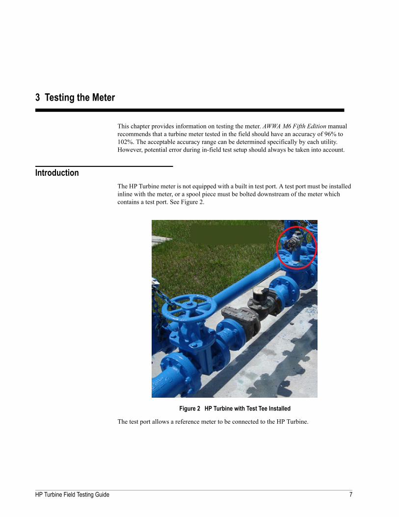
IntroductionThe HP Turbine meter is not equipped with a built in test port. A test port must be installed inline with the meter, or a spool piece must be bolted downstream of the meter which contains a test port. See Figure 2.
Figure 2 HP Turbine with Test Tee Installed
The test port allows a reference meter to be connected to the HP Turbine.
HP Turbine Field Testing Guide 7

Testing the Meter
Preparing to TestThis section provides steps to prepare an HP Turbine meter for testing.
The meter should be setup like the diagram in Figure 3.
Figure 3 HP Turbine Test Setup
1 Open the bypass valve.
The register on the meter stops registering flow.
All water is moving through the bypass.
2 Close the downstream isolation valve.
No water can backflow onto the HP Turbine being tested.
3 Keep the valve on the test riser closed, and remove the test plug from the valve. See Figure 4.
Figure 4 Remove Test Plug
Usually, a permanent gate or ball valve is installed in the downstream test port.
8 HP Turbine Field Testing Guide

Testing the Meter
4 Connect the fire hose to the test riser of the meter under test. See Figure 5.
Figure 5 Connect Fire Hose to Meter Under Test
5 Connect the other end of the fire hose to the reference meter. See Figure 6.
Figure 6 Connect Fire Hose to Reference Meter
6 Slowly open the valve on the test riser at the meter under test to pressurize the reference meter.
7 Open the high flow side of the reference meter.
8 Purge any air from the test setup before running the first test. See Figure 7.
Figure 7 Purge Air from Test Setup
9 Close the reference meter valve, after the air has been purged.
The meter under test and the reference meter are at equal pressure, and testing can begin.
HP Turbine Field Testing Guide 9

Testing the Meter
Testing the HP Turbine MeterThe section provides steps to test the HP Turbine meter.
1 Record the initial reading from the register on the meter under test. See Figure 8.
Figure 8 Register on Meter Under Test
2 Record the initial reading from the register on the reference meter. See Figure 9
Figure 9 Register on Reference Meter
3 Run the low flow test first according to Table 2 on page 5.
4 Run the test until the volume shown in Table 3 on page 6 has been accumulated. The test should be run for a minimum of 3 minutes.
5 Record the consumption from the meter under test.
6 Record the consumption from the reference meter.
7 Calculate the accuracy by dividing the consumption of the meter under test by the consumption of the reference meter.
8 Repeat these steps for the medium and high flow tests.
Proper testing protocol for a meter in the field is to test the low side before testing medium and high flow.
10 HP Turbine Field Testing Guide

Testing the Meter
After the Test is CompleteAfter completing the test, back-flush the line to avoid sending dirty water to the customer.
1 Close the test riser.
2 Shut down the inlet valve of the meter under test.
3 Reopen the inlet valve upstream of the meter under test.
This breaks up any debris built up on the seat of the isolation valve upstream of the meter. See Figure 10.
Figure 10 Inlet Valve
4 Slowly open the test riser.
5 Open the high side of the reference meter to back-flush the meter. See Figure 11.
Figure 11 Back-Flushing the Meter
6 Run until the water coming out of the reference meter turns from brown to clear. See Figure 12 and Figure 13.
Figure 12 Color of Back-Flush Water
Figure 13 Clear Water After Back-Flush
HP Turbine Field Testing Guide 11

Testing the Meter
Breakdown and CleanupComplete the following steps:
1 Close the valve at the test riser attached to the meter under test. See Figure 14.
Figure 14 Test Riser Valve Attached to Meter Under Test
2 Open the high side valve on the reference meter slowly.
3 Inspect the pressure gauge at the reference meter to make sure all pressure has been vented before disconnecting the fire hose. See Figure 15.
Figure 15 High Side Valve on Reference Meter
4 Disconnect the fire hose form the test riser and the reference meter and remove it from the test. site.
5 Open the isolation valve downstream of the meter under test. See Figure 16.
Figure 16 Isolation Valve - Downstream of the Meter Under Test
The reference meter and the fire hose running from the meter under test to the reference meter are depressurized.
12 HP Turbine Field Testing Guide

Testing the Meter
6 Close the bypass valve. See Figure 17.
Full service is restored to the meter monitoring the site.
Figure 17 Bypass Valve
7 Ensure the registers on the meter under test are registering flow.
HP Turbine Field Testing Guide 13

4 Troubleshooting
This chapter provides information on how to achieve a successful test.
Before and During the TestBefore and during a test, ensure the following:
• Start with low flow then move to high flow for a used meter.
• Start with high flow then move to low flow for a new meter.
• Check the pressure gauge at the reference meter to be sure it maintains 20-30 psi to avoid cavitation, which causes faulty results.
• Require calibration certificates for all reference meters. If the reference meter is inaccurate, then it shows the meter under test to be inaccurate.
• Check all connections, hoses, and meters for any leaks. Leaks can cause the meter under test to appear inaccurate.
Poor Low Flow ResultsIf you achieve poor low flow results, try the following.
• Clean the upstream strainer.
• Make sure your downstream isolation valve is fully sealed and is not allowing the bypass to register on the reference meter. This can be achieved by working the downstream isolation valve open and shut several times.
• Check for signs of wear on older meters.
• Replace the UME. As meters wear over time their low flow can be the first to diminish.
See the HP Turbine Installation and Maintenance guide for instructions on servicing the HP Turbine meter..
14 HP Turbine Field Testing Guide

Troubleshooting
Poor Medium Flow ResultsIf the low flow test is accurate and you achieve a poor medium flow test, this could be an indication of a test setup issue. Consider the following.
• Check the stainer upstream of the meter and clear any debris.
• Check the meter to make sure the seal tube is present (if needed).
• Make sure you are maintaining pressure at your reference meter and all air is purged from the line.
Poor High Flow ResultsIf the low flow test is accurate and you achieve a poor high flow test, this could be an indication of a test setup issue. Consider the following.
• Check the stainer upstream of the meter and clear any debris.
• Check the meter to make sure the seal tube is present (if needed).
• Make sure you are maintaining pressure at your reference meter and all air is purged from the line.
Other Sources of ErrorThe following is a list of possible sources of error.
• Reading resolution of registers on the reference meter and meter under test
The error related to reading resolution of the meter is lessened as more water is run through the reference meter and the meter under test.
• Reading resolution of tank/reference unit
– A volumetric test consists of capturing the water run through the meter under test in a volumetric tank.
– The water captured in the tank is usually read with a sight gauge. The accuracy of this reading is dictated by the resolution on the sight gauge.
– The error associated with reading the sight gauge is lessened as more water is run through the reference meter and into the tank.
• Human error
• Poor flow profile
– Is the install correct? Does the meter have the appropriate amount of straight pipe before and after the meter?
– Are isolation valves fully open or fully closed as required?
• Leaky test setup
HP Turbine Field Testing Guide 15
Troubleshooting
• Isolation valves allowing water to bypass
– Are the isolation valves fully shut off?
– Has the reference meter registered more water than the meter under test?
– Has a test failed? You are advised to work the isolation valves fully closed and then open. Doing this helps to break debris from the valve seat of the isolation valve ensuring complete isolation of the meter under test.
• Pressure loss between meter under test and reference meter causing cavitation
• Testing from improper meter plug or port
• Maximum flow exceeding the test setup capacity
If erroneous results occur, repeat test setup checks.
• Make sure the test results are repeatable.
• Check for cavitation or loss of pressure at the reference meter. See “Cavitation” below.
• Check the setup for any leaks.
• Make sure that the downstream isolation valve is closed.
• Make sure at least one full sweep hand of consumption was run.
CavitationCavitation occurs when the water passing through the meter has dropped in pressure to a point where it can “cavitate”. This can occur at any flow rate if pressure at the inlet is low. In effect, the water is boiling because the pressure has become too low.
In order to ensure you are not cavitating, a pressure gauge should be maintained at the reference meter that shows the psi at or above 20-30 psi. If the pressure is close to 30 psi at the reference meter, and has a poor accuracy test, it is recommended to adjust the test setup until the pressure is above 30 psi.
16 HP Turbine Field Testing Guide

5 Contacting Neptune Customer Support
Within North America, Neptune Customer Support is available Monday through Friday, 7:00 AM to 5:00 PM Central Standard Time by telephone, email, or fax.
By PhoneTo contact Neptune Customer Support by phone, complete the following steps.
1 Call (800) 647-4832.
2 Select one of the following options:
– Press 1 if you have a Technical Support Personal Identification Number (PIN).
– Press 2 if you do not have a Technical Support PIN number.
3 Enter the six digit PIN number and press #.
4 Select one of the following options.
– Press 2 for Technical Support.
– Press 3 for maintenance contracts or renewals.
– Press 4 for Return Material Authorization (RMA) for Canadian Accounts.
You are directed to the appropriate team of Customer Support Specialists. The specialists are dedicated to you until the issue is resolved to your satisfaction. When you call, be prepared to give the following information.
– Your name and utility or company name.
– A description of what occurred and what you were doing at the time.
– A description of any actions taken to correct the issue.
By FaxTo contact Neptune Customer Support by fax, send a description of your problem to (334) 283-7497. Please include on the fax cover sheet the best time of day for a customer support specialist to contact you.
By EmailTo contact Neptune Customer Support by email, send your message to [email protected].
HP Turbine Field Testing Guide 17

Contacting Neptune Customer Support
Notes
18 HP Turbine Field Testing Guide

Appendix A: HP Fire Service Turbine Stainless Steel (S) Meter
This appendix provides information on Neptune’s Fire Service meter.
IntroductionThe High Performance (HP) Fire Service Turbine Stainless Steel (S) meter offers some of the widest flow ranges on any fire service turbine meters on the market. All HP Fire Service Turbine S meters meet or exceed the latest AWWA Standard C703. Maximum continuous flow rates can be exceeded by as much as 25% for intermittent periods.
Figure 18 6-Inch Fire Service Turbine S Meter
Systems CompatibilityAll HP Fire Service Turbine S meters are guaranteed adaptable to our ARB® V, ProRead™ (ARB VI), E-Coder®)R900i™, E-Coder®)R450i™, E-Coder®, TRICON®/S, TRICON/E®3, and Neptune readings systems without removing the meter from service.
HP Turbine Field Testing Guide 19

Appendix A
ConstructionThe HP Fire Service Turbine S meter consists of a stainless steel fire service strainer, a rugged lead free high copper alloy maincase, an AWWA Class II turbine measuring element, and a roll-sealed register.
The Unitized Measuring Element (UME) allows for quick, easy, in-line interchangeability. Water volume is measured accurately at all flows by a specially-designed assembly. The hydrodynamically-balanced, thrust-compensated rotor relieves pressure on the thrust bearing. Stationary stainless steel shafts minimize wear and provide sustained accuracy over an extended operating life. Direct coupling of the rotor to the gear train eliminates revenue loss due to slippage during fast starts and line surges. A calibration vane allows in-field calibration of the UME to lengthen service life and to ensure accurate registration.
The roll-sealed register eliminates leaking and fogging. A magnetic drive couples the register with the measuring element. For reading convenience, the register can be mounted in any one of four positions on the meter.
Key FeaturesThis section provides information on the key features of the HP Fire Service Turbine S meter.
Turbine Measuring Element
The key features of the turbine measuring element are:
• UL listed
• FM approved
• Wide flow ranges available at 98.5% - 101.5% accuracy
• Calibration vane
• Hydrodynamically-balanced rotor
• Reusable O-ring gasket provides superior seal
Lead Free Maincase
The key features of the maincase are:
• Certified NSF/ANSI 61 and 372
• Made from lead free high copper alloy
• Proven lifetime material
• Corrosion-resistant
Stainless Steel Strainer
The key features of the stainless steel strainer are:
20 HP Turbine Field Testing Guide

Appendix A
• Permits full flow while stopping debris.
• Meets UL/FM fire service requirements.
Roll-Sealed RegistersThe key features of the roll-sealed register are:
• Low torque registration, magnetic-driven
• Low-flow indicator
• In-line serviceability
• Tamperproof seal design
WarrantyThe stainless steel fire service HP Turbine carries a 10/10 warranty for the strainer body, a lifetime guarantee for the HP Turbine main case, and a one year AWWA performance guarantee for the turbine measuring element.
SpecificationsThis section provides the specifications of the HP Fire Service Turbine S meter.
• Application: cold water measurement of flow in one direction
• Maximum operating water pressure: 175 psi (1206 kPa)
• Registers: direct reading, center-sweep, roll-sealed magnetic drive with low flow indicator
• Measuring element: hydrodynamically-balanced rotor, AWWA Class II turbine
• Stainer: stainless steel body, stainless steel basket strainer element NSF/ANSI 61 certified, UL listed, and FM approved
• Bolts: 300 series stainless steel bolts
HP Turbine Field Testing Guide 21

Appendix A
OptionsThis section provides information on the different options available with the HP Fire Service Turbine S meter.
• Sizes: 3 inch, 4 inch, 6 inch, 8 inch, and 10 inch
• Strainer: 300 series stainless steel or epoxy coated cover
• Units of measure: U.S. gallons, imperial gallons, cubic feet, cubic meters
• Register types:
— Remote reading system*: ProRead, E-Coder)R900i, E-Coder)R450i, E-Coder, TRICON/S, and TRICON/E3
— Reclaim
• Companion flanges: cast iron and bronze (3 inch and 4 inch only)
Operating CharacteristicsThe following table provides information on the operating characteristics of the HP Fire Service Turbine S meter.
* Consult factory for meter performance specifications when fitted with ARB.
Table 4 HP Fire Service Turbine S Operating Characteristics
Meter SizeNormal Operating
Range @ 100% Accuracy (+/- 1.5%)
Maximum Intermittent Flow
AWWA Standard
3 inch5 to 450 US gpm
1.14 to 102.2 m3/h
560 US gpm
127.2 m3/h
8 to 350 US gpm
1.8 to 79.5 m3/h
4 inch 10 to 1200 US gpm
2.27 to 272.5 m3/h
1500 US gpm
340.7 m3/h
15 to 630 US gpm
3.4 to 143. m3/h
6 inch 20 to 2500 US gpm
4.55 to 567.8 m3/h
3100 US gpm
704.1 m3/h
30 to 1400 US gpm
6.8 to 317.9 m3/h
8 inch 35 to 4000 US gpm
7.95 to 908.5 m3/h
5000 US gpm
1135.6 m3/h
50 to 2400 US gpm
11.4 to 545 m3/h
10 inch 50 to 6500 US gpm
11.36 to 1476.4 m3/h
8000 US gpm
1817 m3/h
75 to 3800 US gpm
17.0 to 863 m3/h
22 HP Turbine Field Testing Guide

Appendix A
DimensionsThis section provides the dimensions of the HP Fire Service Turbine S meter.
Figure 19 HP Fire Service Turbine Dimensions
Table 5 HP Fire Service Turbine S Dimensions
Meter SizeA
in/mmB
in/mmC
in/mmD
in/mmE
in/mmF
in/mmG
in/mmWidthin/mm
Weightlbs/kg
3 inch 14 1/8
359
12
305
10 3/4
273
10 5/8
270
17 1/2
445
26 1/8
664
2
51
13 1/2
343
150
68
4 inch 21
533
14
356
10 3/4
273
10 5/8
270
17 1/2
445
35
889
2
51
13 1/2
343
200
91
6 inch 26 7/8
683
18
457
11 3/8
289
11 1/16
281
21 1/4
540
44 7/8
1140
3
76
19
483
425
139
8 inch 31 5/16
795
20
508
13 29/64
342
11 13/16
300
25 7/8
657
51 5/16
1303
3
76
25
635
600
272
10 inch 30
782
26
660
15
381
14 13/16
376
30 1/16
764
56
1422
3
76
27 1/2
699
750
340
HP Turbine Field Testing Guide 23

Appendix A
Cleaning the Fire Service StrainerThis section provides steps for cleaning the stainer attached to the HP Fire Service Turbine S meter.
1 Remove the cover. See Figure 20.
Figure 20 HP FS Strainer Cover
2 Remove the basket from the strainer housing. See Figure 21.
Figure 21 HP FS Strainer Basket
3 Flush out any debris that has built up inside the strainer housing.
4 Inspect the basket strainer for any defects. See Figure 22.
Figure 22 Inspect Strainer Basket
The cover is very heavy and could cause serious injury if proper precautions are not taken. Be sure to lift the cover with the hook provided.
24 HP Turbine Field Testing Guide

Appendix A
5 Reinstall or replace the strainer basket.
6 Inspect the O-ring for any signs of nicks or damage. See Figure 23.
7 Reinstall or replace the O-ring.
Figure 23 Inspect O-Ring
8 Reinstall the cover to complete maintenance.
O-ring
HP Turbine Field Testing Guide 25

Appendix A
Notes:
26 HP Turbine Field Testing Guide

Appendix B: Reading a Register
It is important to become familiar with the information available on a meter.
E-Coder RegisterTo read your Neptune E-Coder® register, expose the solar panel to sunlight or shine a bright light (flashlight or cell phone flashlight), and the display activates.
Figure 24 E-Coder Register
When activated, the LCD display first shows a segment test:
Figure 25 E-Coder LCD Display
This screen is followed by the display of the E-Coder’s manufacturing configuration, and two reading screens.
HP Turbine Field Testing Guide 27

Appendix A
The LCD display shows the current read with comma separators and a decimal place. After initial activation, this screen displays for 20 seconds before toggling to the rate screen. Each additional read screen displays for 8 seconds. Figure 26 shows a reading value of 179.21 (one hundred, seventy-nine) U.S. gallons.
Figure 26 Reading Value
When the screen toggles, the rate of flow is visible and shows gallons per minutes for 4 seconds. Then it toggles back to the read screen. Figure 27 shows a flow rate of 50.7 gpm.
Figure 27 Rate Flow
The following table shows icons and information displayed on the LCD screen.
Table 6 Icons and Displays
Flow/Leak indicator shows the direction of flow through the meter.
ON Water in use.
OFF Water not in use.
Flashing Water is running slowly/low flow indication.
Leak indicator displays a possible leak.
OFF No leak indicated.
Flashing Intermittent leak indicated. Water used during at least 50 of the 96 15-minute intervals during the previous 24-hour period.
Continuous ON Continuous leak indicated. Water used during all 96 15-minute intervals during the previous 24-hour period.
Nine-digit LCD displays the meter reading in billing units of measure. The number is shown in odometer style, reading left to right.1. First four digits - Typical billing digits.2. Last three digits - Testing units used for meter testing.3. Fifth and sixth reading digits - Reading units.
28 HP Turbine Field Testing Guide

Appendix C: Analytical Tool
This appendix discusses Neptune’s analytical tool called Statistical Evaluation for Enhancement of Revenue (SEER®).
SEERDuring its more than 15 years in operation, the Neptune Technology Services Group tested over 10,000 large meters of various makes, sizes, and ages. Neptune ran these test results through a multiple linear regression analysis to determine which factors affected meter accuracy. This analysis showed key variables that impact water meter accuracy.
The result of this study is Neptune’s analytical tool called SEER. The SEER model can determine meter accuracy to within a 95% confidence interval. This allows the utility to quickly determine which meters to replace first and how quickly the resulting increase in revenue pays for the cost of installing a new meter.
Key FeaturesSEER has several key features.
• Provides analysis for large meters and residential positive displacement meters
• Offers meter accuracy to within a 95% confidence interval
• Highlights misapplication of meters
• Provides reporting functions
• Offers importing and exporting features
Key BenefitsSEER has several key benefits.
• Identifies which meters need attention
• Establishes priorities based on revenue gain and payback
• Allows implementation of targeted revenue enhancement program.
• Indicates possible meter failures, wrong-sizing, and theft
HP Turbine Field Testing Guide 29

Appendix B
Benefits to the UtilityIncreased revenue can be used by the utility to focus on:
• Changing out meters
• Managing operating costs
• Improving infrastructure
• Handling rising water demands
• Preventing increases in water rates
• Reducing water loss
• Increasing meter reading efficiencies
• Recovering revenue
• Implementing effective meter maintenance programs
• Increasing resources
• Replacing an aging meter population
• Updating meter databases
Reporting FunctionOften utilities know that their meters are inaccurate but are not sure of the level of inaccuracy. SEER makes it easy for the utility manager to determine meters that need to be replaced and to set replacement priorities. SEER allows for easy presentation of the information gained from the program. The program allows you to import meter data and capture and import screens into a presentation or a text document. Analysis results can also be exported and printed using the reporting function within SEER.
SoftwareThe SEER software can be found on-line at www.neptunetg.com. Each user is required to complete an on-line registration form. Upon approval, the user is granted a level of access to features within the program. Features include SEER data entry, storing of SEER reports, import and export, serial number look-up tables, as well as charting and graphing capabilities.
All registered users have access to the latest desktop version of SEER and it can be obtained at the following link on the Neptune website.
http://www.neptunetg.com/water-meters/online-tools/
30 HP Turbine Field Testing Guide

Glossary
AWWA American Water Works Association
calibrate Correlated readings of an instrument with those of a standard in order to check the instruments accuracy
cavitation Rapid formation and collapse of vapor pockets in a flowing liq-uid in regions of very low pressure
gravimetric Weighted scale
master meter Known good meters
meter under test Meter at the test side for which you are performing the field test
reference meter Meter you bring to the test site as a standard that the meter under test is checked against
SEER Statistical Evaluation for Enhancement of Revenue
UME Unitized Measuring Element
volumetric Calibrated tank
HP Turbine Field Testing Guide 31

Glossary
Notes:
32 HP Turbine Field Testing Guide

Index
A
accuracy 2, 7meter 1, 29reading 15
application 21AWWA 1, 31
B
basket strainer 21boiling 16bypass valve 8
C
calibratescale 2tank 2
calibrationcertificate 2, 3, 14vane 20
cavitation 3, 14, 16certificates 14companion flanges 22comparison 2confidence interval 29corrosion 20customer support 17
D
debris 21dimensions 23direct reading 21displacement 29downstream 1, 16
E
email 17
F
fax 17flow rate 5FM 20
G
gasket 20gauge 15gravimetric 2
H
high flow 14hydrodynamically 20, 21
I
isolation valve 1, 2, 8, 15, 16
L
LCD 28leaks 14, 16low flow 14
M
maincase 20maintenance 1master meter 2
O
operating characteristics 22options 22
P
phone 17pressure loss 16psi 14
R
reading resolution 15recommended tools 3reference meter 3, 15registration capacity 21resolution 15revenue 1, 29, 30revolution 6rotor 20
S
seal 20, 21seal tube 15SEER® 29serviceability 21setup recommendations 3sight gauge 15snap shot 2sources of error 15
HP Turbine Field Testing Guide 33

Index
straight pipe 15strainer 14sweep hand 6
T
T-10, bypass 3test
port 7setup 7
testing methods 1tool kit 4
U
UL 20UME 14
V
volume 6volumetric 2, 15volumetric tanks 2
W
wet tank 2
34 HP Turbine Field Testing Guide


neptunetg.com
TAKE CONTROL
FT HP Turbine 01.16 Part No. 13505-012 © Copyright 2016, Neptune Technology Group Inc. Neptune is a registered trademark of Neptune Technology Group Inc.
Neptune Technology Group Inc.1600 Alabama Highway 229Tallassee, AL 36078USATel: (800) 633-8754Fax: (334) 283-7293
Neptune Technology Group (Canada) Ltd.7275 West Credit AvenueMississauga, OntarioL5N 5M9CanadaTel: (905) 858-4211Fax: (905) 858-0428
Neptune Technology Group Inc.Avenida Ejército Nacional No. 418Piso 12, Despacho 1203Colonia Polanco V Seccion, C.P. 11560Delegación Miguel HidalgoMéxico, Distrito FederalTel: (525) 55203 5294 / (525) 55203 4032 (525) 55203 6204Fax: (525) 55203 6503