fuel injection technical information
TRANSCRIPT
8/6/2019 Fuel Injection Technical Information
http://slidepdf.com/reader/full/fuel-injection-technical-information 1/6
CARBURETOR REPAIR manuals & parts service sheets for Rochester Holley Carter Stromberg
Corvette Service Manuals
Holley Carb Manuals
Oldsmobile Service Manuals
Tri Power Carburetor
anuals
Dual Quad Carburetor
anuals
Carter Carburetor Manuals
Rochester Carburetor
anuals
Rochester Quadrajet
anuals
Fuel Injection Manuals
Misc Carbs and Marine
anuals
Transmission Manuals
Pontiac Manuals
Pontiac Brochures
Chevrolet Manuals
Chevrolet Brochures
Buick Service Manuals
Motorcycle Repair Service
anual
Cadillac Service shop
anuals
ew All P roducts
Copyright © 2005-2006 Carburetor-Manual.com
Corvette Service
Manuals
Holley Carb
Manuals
Oldsmobile Serv
Manuals
Tri Power
Carburetor
Manuals
Dual Quad
Carburetor
Manuals
Carter Carburet
Manuals
Rochester
Carburetor
Manuals
Rochester
Quadrajet Manuals
Fuel Injection
Manuals
Misc Carbs and
Marine Manuals
Transmission
Manuals
Pontiac Manua
8/6/2019 Fuel Injection Technical Information
http://slidepdf.com/reader/full/fuel-injection-technical-information 2/6
TERMS AND DEFINITIONS OFFUEL INJECTIONMANAGEMENT SYSTEMS
Throttle Body Assembly (TBA) — The throttle bodyassembly (also called air valve), controls the airflow to theengine through one, two or four butterfly valves andprovides valve position feedback via the throttle positionsensor. Rotating the throttle lever to open or close thepassage into the intake manifold controls the airflow to theengine. The accelerator pedal controls the throttle lever posi-tion. Other functions of the throttle body are idle bypass aircontrol via the idle air control valve, coolant heat for avoidingicing conditions, vacuum signals for the
ancillaries and the sensors.
FUELINJECTOR — There are basically three approaches indelivering the fuel to the engine:
• Above the throttle plate as in throttle body injection
• In the intake port toward the intake valves as in multi-port injec-tion or central multi-port injection.
• Directly into the combustion chamber as in gasoline direct injec-tion systems (GDI).
The fuel injector is continuously supplied with pressurized fuelfrom the electric fuel pump. The pressure across the meteringorifice of the injector is maintained constant by the fuel pressureregulator. The fuel injector is an electromagnetic valve that
when driven by the ECU delivers a metered quantity of fuel intothe intake manifold (or combustion chamber in the GDI system).The ECU controls the fuel flow by pulse width modulation. Thetime the injector is driven into an open condition is determinedby the following sensor inputs:
• Engine RPM
• Throttle position (TPS)
• Manifold absolute pressure or mass air flow
• Engine coolant temperature
• Oxygen sensor feedback voltage
• Intake air charge temperature
• Battery voltage
CENTRALPOINT INJECTION SYSTEM (CPI) — Electronic fuel
Injection system consisting on a single fuel injector mounted inthe throttle body.
DIGITALFUELINJECTION (DEFI OR DFI) — Electronic fuelinjection system controlled by digital microprocessors asopposed to earlier systems that were of analog design. Theanalog input signals to the microprocessor are converted fromanalog to digital before being processed.
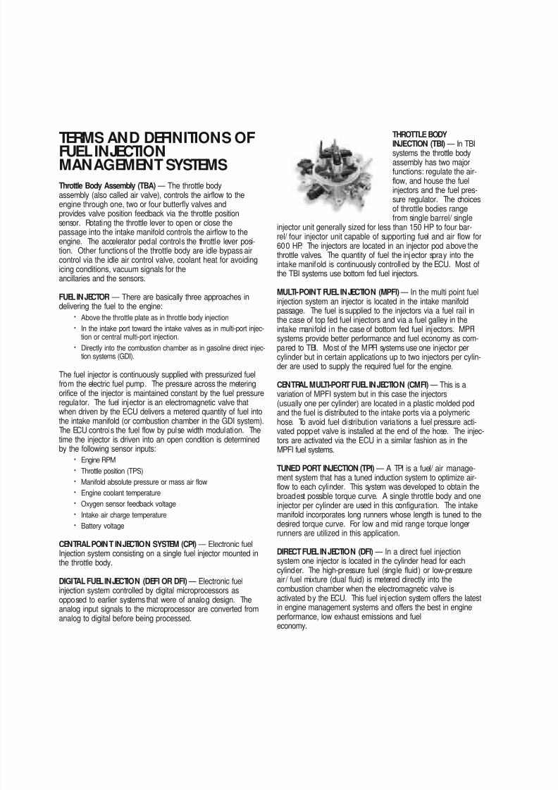
THROTTLE BODYINJECTION (TBI) — In TBIsystems the throttle bodyassembly has two majorfunctions: regulate the air-flow, and house the fuelinjectors and the fuel pres-sure regulator. The choicesof throttle bodies rangefrom single barrel/ single
injector unit generally sized for less than 150 HP to four bar-rel/ four injector unit capable of supporting fuel and air flow for600 HP. The injectors are located in an injector pod above thethrottle valves. The quantity of fuel the injector spray into theintake manifold is continuously controlled by the ECU. Most of
the TBI systems use bottom fed fuel injectors.
MULTI-POINT FUELINJECTION (MPFI) — In the multi point fuelinjection system an injector is located in the intake manifoldpassage. The fuel is supplied to the injectors via a fuel rail inthe case of top fed fuel injectors and via a fuel galley in theintake manifold in the case of bottom fed fuel injectors. MPFIsystems provide better performance and fuel economy as com-pared to TBI. Most of the MPFI systems use one injector percylinder but in certain applications up to two injectors per cylin-der are used to supply the required fuel for the engine.
CENTRAL MULTI-PORT FUELINJECTION (CMFI) — This is avariation of MPFI system but in this case the injectors(usually one per cylinder) are located in a plastic molded pod
and the fuel is distributed to the intake ports via a polymerichose. To avoid fuel distribution variations a fuel pressure acti-vated poppet valve is installed at the end of the hose. The injec-tors are activated via the ECU in a similar fashion as in theMPFI fuel systems.
TUNED PORT INJECTION (TPI) — A TPI is a fuel/ air manage-ment system that has a tuned induction system to optimize air-flow to each cylinder. This system was developed to obtain thebroadest possible torque curve. A single throttle body and oneinjector per cylinder are used in this configuration. The intakemanifold incorporates long runners whose length is tuned to thedesired torque curve. For low and mid range torque longerrunners are utilized in this application.
DIRECT FUELINJECTION (DFI) — In a direct fuel injectionsystem one injector is located in the cylinder head for eachcylinder. The high-pressure fuel (single fluid) or low-pressureair/ fuel mixture (dual fluid) is metered directly into thecombustion chamber when the electromagnetic valve isactivated by the ECU. This fuel injection system offers the latestin engine management systems and offers the best in engineperformance, low exhaust emissions and fueleconomy.
8/6/2019 Fuel Injection Technical Information
http://slidepdf.com/reader/full/fuel-injection-technical-information 3/6
8/6/2019 Fuel Injection Technical Information
http://slidepdf.com/reader/full/fuel-injection-technical-information 4/6
140
TOP-FED FUELINJECTOR —When the ECU activates thiselectromagnetic valve, the injec-tor meters and atomizes fuel infront of the intake valve. Thefuel enters the top and is dis-charged via the metering orifice
at the bottom at high pressure. The spray geometry and crosssectional area is specific to the engine application. In generalthere are four major spray patterns:
• Pencil stream. Solid stream narrow angle spray.
• Split pencil stream. Two solid streams narrow angle spraysusually used in multi valve cylinder appl ications.
• Bend spray. Solid stream narrow angle spray being dis-charged in an angle with respect to the injector center axis.This application is used in engine applications where the injec-tor package does not allow alignment of the injector axis withthe spray target center axis.
• Oblong spray. This spray geometry consists of an elliptic oroblong cross-sectional area of the spray. This application isused in engine applications where the spray target requires aspecific spray pattern.
BOTTOM FED FUELINJECTOR —This electromagnetic valve metersfuel into the intake manifold inproportion to the air flowing intothe engine. When the valve isenergized the electromagneticforce generated by the solenoidlifts the pintle/ ball from the seat.Fuel under pressure is then inject-
ed into the throttle body bore or the intake port. The spray con-figuration is application dependent. For throttle body injectiona hollow conical spray is required while for port injection a nar-row pencil stream is preferred to avoid wall wetting.
HIGH IMPEDANCE INJECTORS — Most injectors can be dividedinto two major categories: high impedance 12 to 16 Ohms andlow impedance 1.2 to 4.0 Ohms. The high impedance injectorsare used with ECUs that are designed with saturation drivers.The advantage of using saturation drivers is that the currentsrunning through the ECU circuits and the injectors are rela-tively low thus generating less heat. The disadvantage of satu-ration drivers is that the driver has a slower response time,which could affect the full utilization of such a system at veryhigh engine RPM.
LOW IMPEDANCE INJECTORS — The low impedance injectorsare designed to be run with an ECU that employs peak andhold drivers (also called current sensing or current limiting driv-ers). The current ratio (peak to hold) is generally 4:1 and themost common drivers available are 4 A peak/ 1 A hold or 2 Apeak/ 0.5A hold. The peak current is generated to overcomethe inertia of the closed valve and once the valve is open thedriver cuts down to 1/ 4 of the peak current to hold the injectoropen until the end of the metering event. Low impedance injec-tor designs are mostly used in high flow applications.
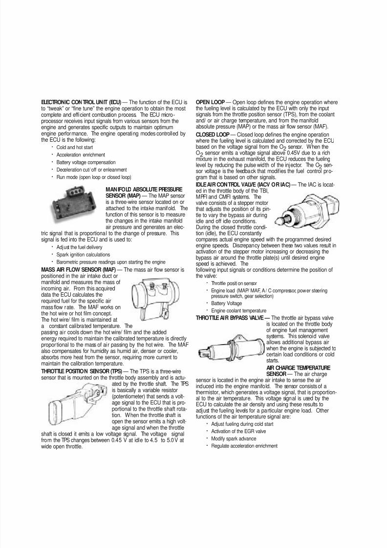
COOLANT TEMPERATURE SENSOR
— The coolant temperature sen-sor is a two-wire sensor that isthreaded into the engine blockand is in direct contact with thecoolant. The function of this sen-sor is to generate a signal that
the ECU uses to adjust the fueling levels required for the opera-tion of the engine and operate ancillaries. The thermistor con-tained in the sensor generates an electric signal that is propor-tional to the coolant temperature. At low temperatures the resist-ance is high (3800 ohms) generating a 5-volt signal in the ECU.At normal engine operating temperatures the resistance of thesensor is low (180–200 ohms) which generates 1–2 volt signalin the ECU. Other functions of the coolant temperature signalare:
• Idle speed adjustment via the IAC• Modify spark advance
• Electric cooling fan operation
• Activation of the EGR
• Torque converter clutch application
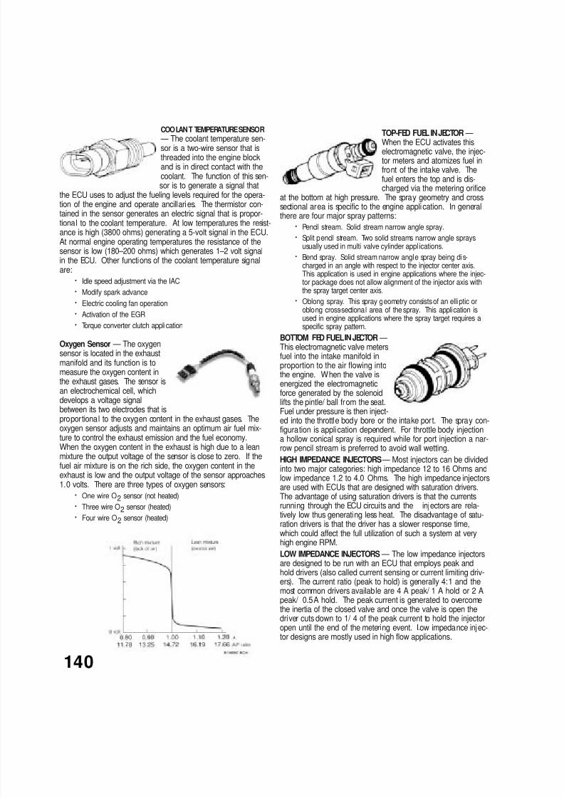
Oxygen Sensor — The oxygensensor is located in the exhaustmanifold and its function is tomeasure the oxygen content inthe exhaust gases. The sensor isan electrochemical cell, whichdevelops a voltage signalbetween its two electrodes that is
proportional to the oxygen content in the exhaust gases. Theoxygen sensor adjusts and maintains an optimum air fuel mix-ture to control the exhaust emission and the fuel economy.When the oxygen content in the exhaust is high due to a leanmixture the output voltage of the sensor is close to zero. If thefuel air mixture is on the rich side, the oxygen content in theexhaust is low and the output voltage of the sensor approaches1.0 volts. There are three types of oxygen sensors:
• One wire O2 sensor (not heated)
• Three wire O2 sensor (heated)
• Four wire O2 sensor (heated)

8/6/2019 Fuel Injection Technical Information
http://slidepdf.com/reader/full/fuel-injection-technical-information 5/6
ELECTRIC IN-LINE FUELPUMP — The function of the electric fuelpump is to deliver pressurized fuel to the fuel injection system.The ECU activates the fuel pump relay to operate the fuel pumpwhen the ignition switch is in the On or start position. Thepumps are designed to match certain flow and pressure specifi-cation for the engine application. In TBI applications the fuelpump must supply enough fuel flow for the engine WOT outputat 15 to 20 psi. In multi-port applications the fuel pump mustbe able to supply enough fuel at full engine load to maintain atleast 43.5 psi at the fuel rai l. At idle the fuel pressure regulatormust be able to return the excess fuel to the tank and maintainthe required system pressure. Most of the cars prior to 1987use an in-l ine external electric fuel pump.
ELECTRIC IN-TANK FUELPUMP — Almost all car applicationsafter 1987 designed their fuelpump assembly inside the fueltank. The advantage of havingthe fuel pump in the fuel tank ismainly lower noise, lower poten-tial leakage problems, less
mounting sensitivity of the pump with respect to lift of fuel fromthe tank is minimized. The in-tank pump went through severaldesigns evolving from a simple “pump on a stick” to a complexin-tank fuel sending modules. The new designs combine thehigh-pressure electric fuel pump, noise isolation and a fuel levelsensor into one compact modular package. This new design
also helps reducing hydrocarbon emissions. The hot gasolinereturning from the fuel system is returned to the reservoir sur-rounding the fuel pump. By returning the hot fuel to the reser-voir heating of the bulk fuel in the fuel tank is avoided, thusreducing the evaporation of the high volatile portions in thefuel. At present all fuel tank modules are designed and serv-iced as a complete unit. If the pump or fuel level sensor failsthe entire unit will have to be changed.
FUELPUMP INLET FILTER — The function of this filter is to elimi-nate any impurities that might harm the fuel pump. In the in-line fuel pump type this filter is external to the fuel tank and isin a replaceable cartridge filter. In the in-tank fuel pumps thefuel filter is in the form of a sock and is directly attached to thepump in the “pump on a stick” version and attached to the fuelpump module in the module version.
MAIN FUELFILTER — Thefunction of this filter is to elimi-nate any contaminants after thefuel pump. These are either smallenough to pass through the fuel
filter of the pump inlet or are gen-erated by the fuel pump. Thisfuel filter is also of the cartridge type but is designed to sustainmuch higher fuel pressures that the fuel pump inlet filter.
FUELPRESSURE REGULATOR — Fuel system pressure ismaintained by the regulator, while excess fuel is returned to thefuel tank. The regulator consists of two chambers separated bya diaphragm assembly. On the fuel side of the diaphragm athrottling valve is employed to expand or restrict fuel flow as thefuel pressure fluctuates. The other side contains a spring withan adjustment screw that is set at the factory for correct systempressure and flow. This chamber is connected to the intakemanifold in MPFI systems to reference the vacuum in the mani-fold during engine operation. This pressure reference is
required to maintain a constant differential pressure across themetering orifice of the fuel injector.
8/6/2019 Fuel Injection Technical Information
http://slidepdf.com/reader/full/fuel-injection-technical-information 6/6
THE ENGINE APPLICATION AND THE SELECTION OF YOURFUELMANAGEMENT SYSTEM COMPONENTS.
INJECTOR FUEL FLOWEngine output is in direct relation with fuel supplied to theengine, however installing injectors, which are too big, will notmake more power. It is therefore very important to match thefuel injector flow characteristics to specific engine applications.Matching the fuel flow characteristics of fuel injectors is as impor-tant as matching the carburetor jets for a specific engine applica-tion. The fuel flow of the injectors and the carburetor has to bematched to the air flow requirements of the engine over a broadRPM operating range.
In the carburetor the operating range is usually divided into threesub-ranges: idle, mid-range and power. Three distinct fuel cir-
cuits supply the fuels for these three ranges. In MPFI systems onesingle injector has to cover all three ranges for individual cylin-ders from 500 RPM at idle to 8000 at W OT. The operatingrange in fuel injectors is normally referred to as the dynamicrange of the injector. An injector with a wide dynamic range iscapable not only to potentially cover several engine applicationsbut also is a very sought after metering tool for high perform-ance applications.
The dynamic range must encompass the minute quantities of fuelrequired at idle conditions and the large quantities of fuelrequired at maximum engine output. It must also cover therequired fuel amounts during transient response. The dynamicrange of the fuel injector is further stressed in turbo chargedapplications because of the additional fuel required due to thehigher engine air mass flow rates generated by the turbocharger.
The following equation sizes fuel injectors for specific engineapplications.
Injector Static Flow Rate [lb/ hr] = (Engine HP * BSFC)/ (Number ofinjectors * DC of Inj.)
Engine HP = Realistic HP output estimate of the engine
BSFC = Brake Specific Fuel Consumption [ lb/ HP*hr].Good approximation 0.50
Duty Cycle of Injector = Maximum opening time of injector/ cycle time.
Maximum Duty Cycle= 0.90
Example:
Engine HP = 400HP
Number of Injectors = 8
Injector Static Flow Rate [lb/ hr] = (400 * 0 .50)/ (8 *0.90) = >27.78 b/ hr
Note: If the application requires a static flow rate that falls inbetween two available injectors always use the next injec-tor with the higher flow rate.
For the example above if only 25 lb/ hr and 30 lb/ hr injectorsare available, choose 30lb/ hr injectors.
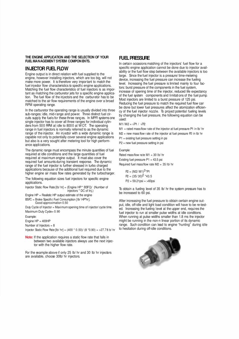
FUEL PRESSUREIn certain occasions matching of the injectors’ fuel flow for aspecific engine application cannot be done due to injector avail-ability or the fuel flow step between the available injectors is toolarge. Since the fuel injector is a pressure/ time-meteringdevice, increasing the fuel pressure can increase the fuelinglevel. Increasing the fuel pressure is limited mainly to four fac-tors: burst pressure of the components in the fuel system,increase of opening time of the injector, reduced life expectancyof the fuel system components and limitations of the fuel pump.Most injectors are limited to a burst pressure of 125 psi.Reducing the fuel pressure to match the required fuel flow canbe done but lower fuel pressures affect the atomization efficien-cy of the fuel injector nozzle. To project potential fueling levelsby changing the fuel pressure, the following equation can be
used:M1/ M2 = √ P1 / √ P2
M1 = rated mass flow rate of the injector at fuel pressure P1 in lb/ hr
M2 = new mass flow rate of the injector at fuel pressure P2 in lb/ hr
P1 = existing fuel pressure setting in psi
P2 = new fuel pressure setting in psi
Example:
Rated mass flow rate M1 = 30 lb/ hr
Existing fuel pressure P1 = 43.5 psi
Required fuel mass flow rate M2 = 35 lb/ hr
P2 = (M2/ M1)2*P1
P2 = (35/ 30)2 *43.5
P2 = 59.21psi = >60psi
To obtain a fueling level of 35 lb/ hr the system pressure has tobe increased to 60 psi.
After increasing the fuel pressure to obtain certain engine out-put, idle, off-idle and light load condition will have to be re-test-ed. Increasing the fueling level at the upper end, requires thefuel injector to run at smaller pulse widths at idle conditions.When running at pulse widths smaller than 1.8 ms the injectormight be running in the non-n linear portion of its dynamicrange. Such condition can lead to engine “hunting” during idleto hesitation during off-idle conditions.