fuel system circuit d'essence … system.pdf · fuel system carburetor removal remove the fuel...
TRANSCRIPT
FUEL SYSTEM CIRCUIT D'ESSENCE
KRAFTSTOFFSYSTEM
41 FUEL SYSTEM SERVICE INFORMATION
TROUBLESHOOTING
FUEL TANK
AIR CLEANER
CARBURETOR REMOVAL
VACUUM CHAMBER
FLOAT CHAMBER
4-1 PILOT SCREW
4-2 CARBURETOR SEPARATION
4-3 CARBURETOR ASSEMBLY
4-4 CARBURETOR INSTALLATION
4-5 PILOT SCREW ADJUSTMENT
4-6 FUEL PUMP
4-7
SERVICE INFORMATION GENERAL
Gasoline is exnemely pmmable and is expIosive under certain conditions. Work in a well ventilared area. Do not smoke or allow flames ar sparks in the work area.
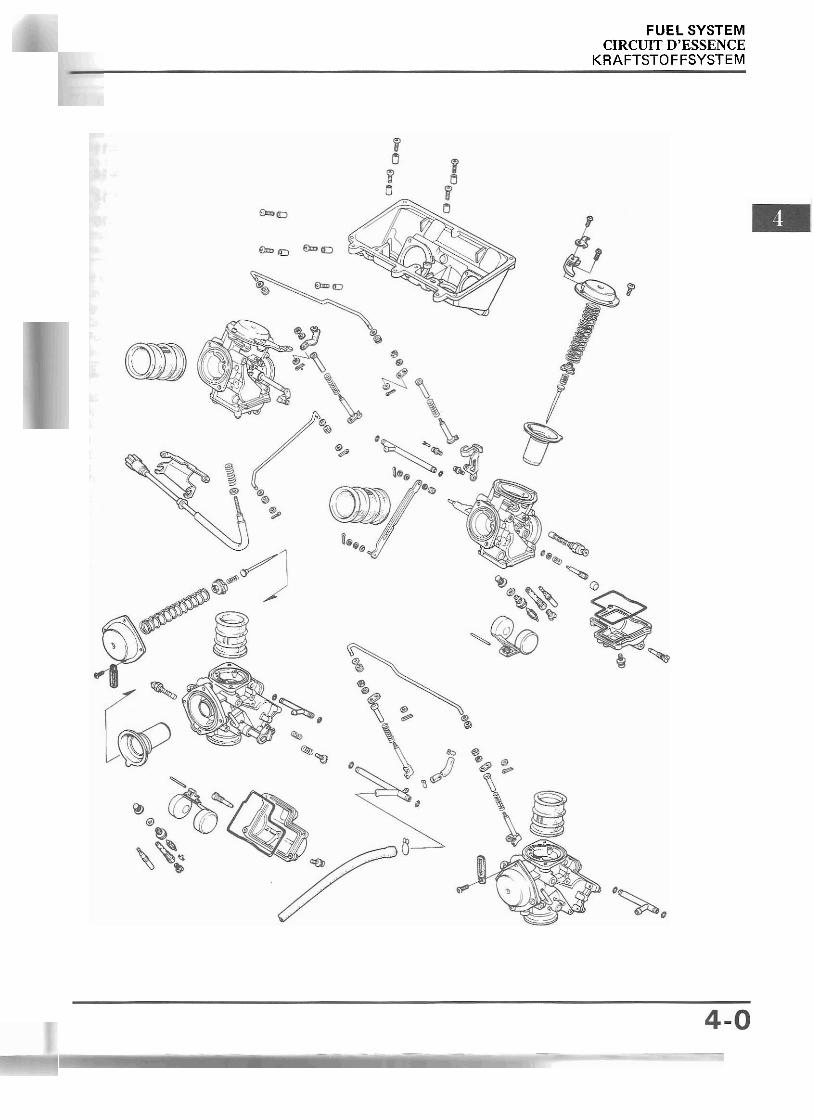
The front cylinders use down draft carburetors. When disassembling fuel system parts, note the locations of the O-rings. Replace them with new ones on reasrembly. The float bowls have drain screws that can be loosened to drain residual gasoline. Fuel pump inspection is in section 21. The No. 1 and No. 3 carburetors use different jet needles (thinner) and shorter springs than the No. 2 and No. 4 carburetors. Do not interchange these parts.
TOOLS
Common Float level gauge
SPECI FICATIONS
l Item Specifications
Carburetor type KEIHIN VD
36 mm (1.42 in)
12.2 mm (0.48 in)
34 mm (1.34 in)
G, SD, AR: VD85F SW: VD85G
F: VD85H Other models: VD85E
Throttle bore
Float level
Pilot screw initial openina 1 See oaoe 4-1 4
Venturi bore
7.5 mm (0.30 in)
Idle speed
Primary
Secondary
Main iet I al ln 1,000t100 min-' irpm)
Identification number
Throttle grip free play 2-6 mm (0.08-0.24 in)
FUEL SYSTEM
TROUBLESHOOTING Engine cranks but won't start
No fuel in tank No fuel to carburetors Engine flooded with fuel No spark a t piug (ignition system faulty) Air cleaner clogged Intake air leak Improper choke operation Improper throttle operation
Hard starting or stalling after starting Improper choke operation Ignition malfunction
. Carburetor faulty Fuel contaminated Intake air leak Idle speed incorrect
Rough idle Ignition system faulty
' Idle speed incorrect Incorrect carburetor synchronization Carburetor faulty Fuel contaminated
Misfiring during acceleration Ignition system faulty
Backfiring Ignition system faulty Carburetor faulty
Poor performance (driveability) and poor fuel economy Fuel system clogged Ignition system faulty
Lean mixture Clogged fuel jets Faulty float valve Float level low Fuel cap vent blocked Fuel strainer screen clogged Restricted fuel line Air vent tube clogged Intake air leak Restricted or faulty fuel pump
Rich mixture Clogged air jet8 Vacuum piston stuck closed Faulty float valve Float level too high Choke stuck or clogged Dirtv air cleaner
FUEL SYSTEM
FUEL TANK
- Do nor allo w flomes or sparks near gasoline. Wipe irp spilled gasoline ar once.
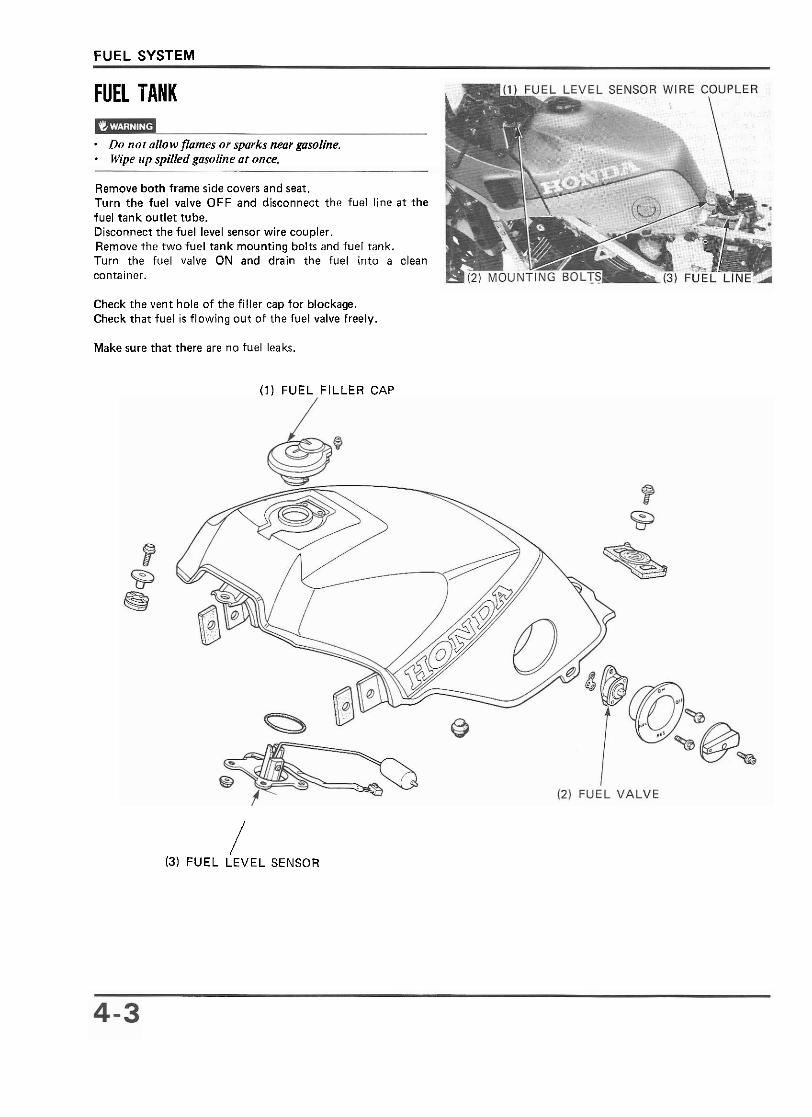
Remove both frame side covers and seat. Turn the fuel valve OFF and disconnect the fuel line at the fuel tank outlet tube. Disconnect the fuel level sensor wire coupler. Remove the two fuel tank mounting bolts and fuel tank. Turn the fuel valve ON and drain the fuel into a clean container.
Check the vent hole of the filler cap for blockage. Check that fuel is flowing out of the fuel valve freely.
Make sure that there are no fuel leaks.
(1) FUEL FILLER CAP
/ (3) FUEL LEVEL SENSOR
FUEL SYSTEM
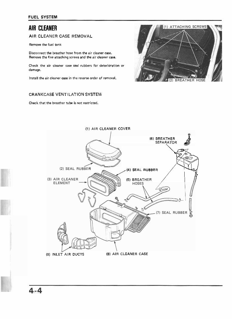
AIR CLEANER AIR CLEANER CASE REMOVAL
Remove the fuel tank
Disconnect the breather hose f rom the air cleaner case. Remove the five attaching screws and the air cleaner case.
Check the air cleaner case seal rubbers for deterioration or damage.
Install the air cleaner case in the reverse order of removal.
CRANKCASE VENTILATION SYSTEM
Check that the breather tube is no t restricted.
( l ) AIR CLEANER COVER
(6) BREATHER SEPARATOR d/
R SEAL RUBBER
(5) BREATHER Y
(9) INLET AIR DUCTS (8) A I R CLEANER CASE
FUEL SYSTEM
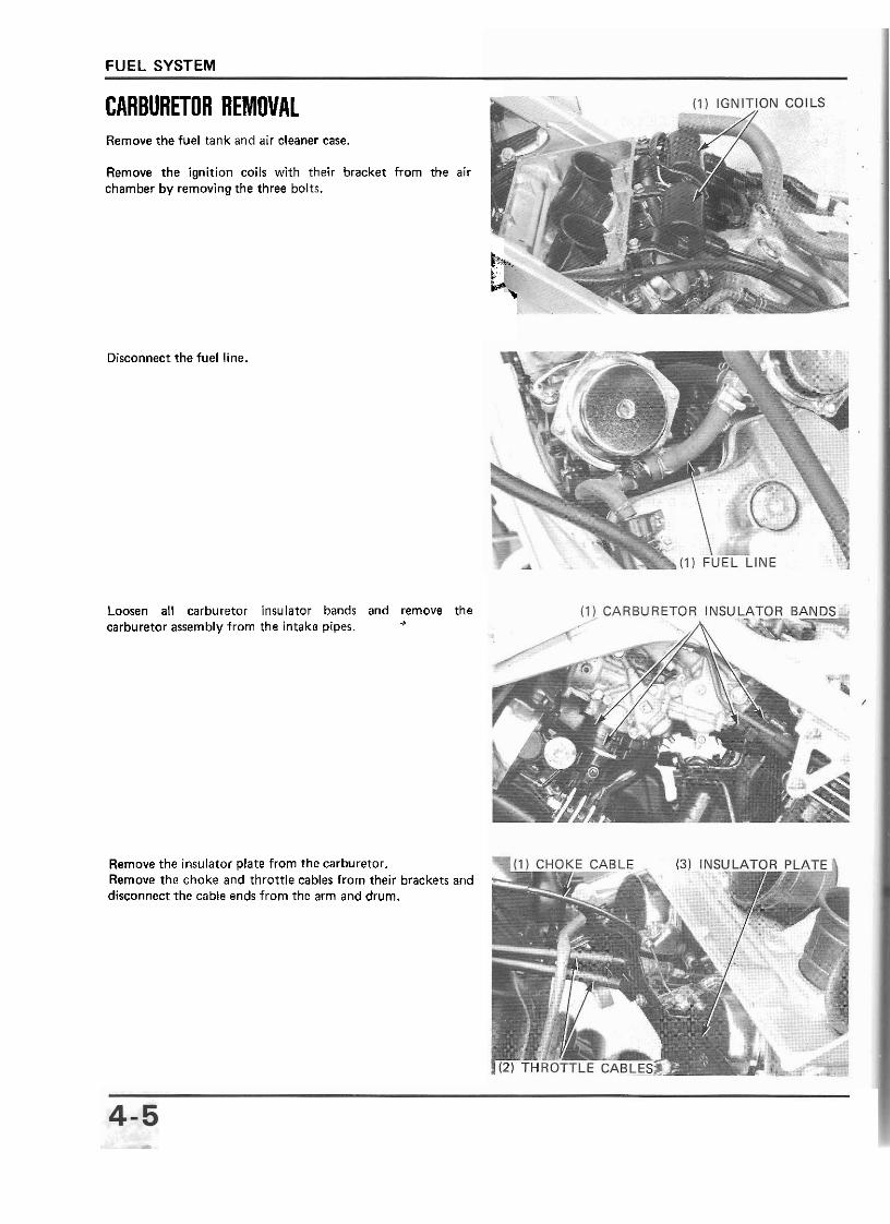
CARBURETOR REMOVAL Remove the fuel tank and air cleaner case.
Remove the ignition coils with their bracket from the air chamber by removing the three bolts.
b h v.
Disconnect the fuel line.
Loosen all carburetor carburetor assembly from
insulator bands and remove the the intake pipes.
Remove the insulator plate from the carburetor. Remove the choke and throttle cables from their brackets disconnect the cable ends from the arm and drum.
and
FUEL SYSTEM
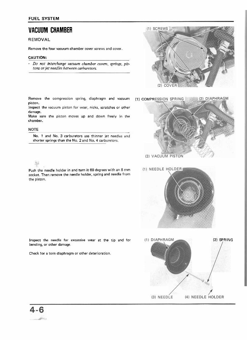
VACUUM CHAMBER REMOVAL
Remove the four vacuum chamber cover screws and cover.
CAUTION:
Do not interchange vacuum chamber covers, springs, pis- tons or jet needles between carburetors.
Remove the compression spring, diaphragm and vacuum piston. Inspect the vacuum piston for wear, nicks. scratches or other damage. Make sure the piston moves up and down freely in the chamber.
NOTE
No. 1 and No. 3 carburetors use thinner jet needles and shorter sorinas than the No. 2 and No. 4 carburetors.
( l ) COMPR
... ~.. ,
Push the needle holder in and turn it 60 degrees with an 8 mm socket. Then remove the needle holder, spring and needle from the piston.
Inspect the needle for excessive wear a t the tip and for (2) SPRING bending, or other damage.
Check for a torn diaphragm or other deterioration.
FUEL SYSTEM
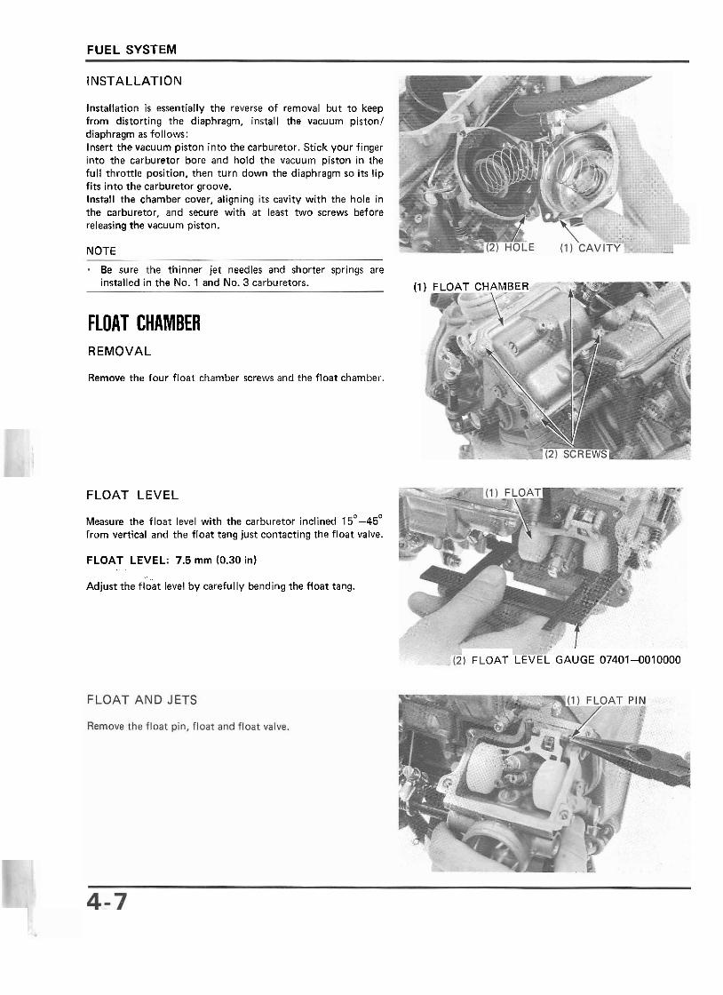
INSTALLATION
Installation is essentially the reverse of removal but to keep from distorting the diaphragm, install the vacuum piston1 diaphragm as follows: Insert the vacuum piston into the carburetor. Stick your finger into the carburetor bore and hold the vacuum piston in the ful1 throttle position, then turn down the diaphragm so i t s lip fits into the carburetor groove. Install the chamber cover, aligning its cavity with the hole in the carburetor. and secure with a t least two screws before releasing the vacuum piston.
NOTE
Be sure the thinner jet needles and shorter springs are installed in the No. 1 and No. 3 carburetors. (l) FLOAT CHAMB'"
FLOAT CHAMBER REMOVAL
Remove the four float chamber screws and the float chamber.
FLOAT LEVEL
Measure the float level with the carburetor inclined 15'-45' from vertical and the float tang just contacting the float valve.
FLOAT LEVEL: 7.5 mm (0.30 in) . .
Adjust the float level by carefully bending the float tang.
) FLOAT LEVEL GAUGE 074014010000
FUEL SYSTEM
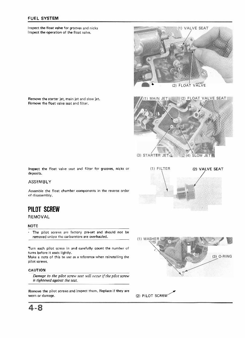
Inspect the float valve for grooves and nicks Inspect the operation of the float valve.
& (2) FLOAT VALVE
Remove the starter jet, main jet and slow jet. Remove the float valve seat and filter.
'a, c n , r i -
Inspect the float valve seat and filter for grooves, nicks or (2) VALVE SEAT deposits. / ASSEMBLY
Assemble the float charnber cornponents in the reverse order of disassembly.
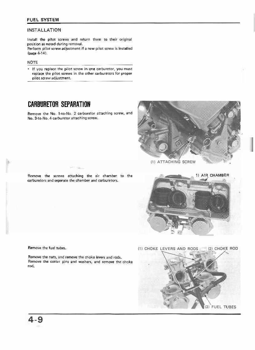
PILOT SCREW REMOVAL
NOTE
The pilot screws are factory pre-set and should not be removed unless the carburetors are overhauled.
.. .
Turn each pilot screw in and carefully count the number of 1' turns before it seats lightly.
' \
Make a note of this to use as a reference when reinstalling the pilot screws.
CAUTION
Damage to the pilot screw sent will occur if the pilot screw is tightened againsf the sent.
Remove the pilot screws and inspect them. Replace i f they are worn or damage. (2) PILOT SCREW
f
FUEL SYSTEM
INSTALLATION
Install the pilot screws and return them to their original position as noted during removal. Perform pilot screw adjustment i f a new pilot screw i s installed (page 4-14).
NOTE - If you replace the pilot screw in one carburetor, you must replace the pilot screwr in the other carburetors for proper pilot screw adjustment.
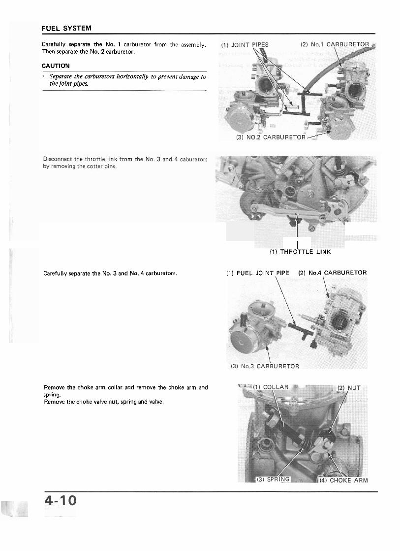
CARBURETOR SEPARATION Remove the No. l-to-No. 2 carburetor attaching screw. and No. 3-to-No. 4 carburetor attaching screw.
Remove the screws attaching the air chamber to the 1 AIR CHAMBER carburetors and separate the chamber and carburetors.
Remove the fuel tuber.
Remove the nuts, and remove the choke levers and rods. Remove the cotter pins and washers, and remove the choke rod.
FUEL SYSTEM
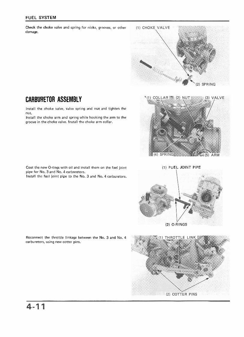
Carefully separate the No. 1 carburetor from the assembly. Then separate the No. 2 carburetor.
CAUTION
Separate the carburetors horirontaily to prevenr damage to the joint pipes.
I (1) THROTTLE LINK
Carefully separate the No. 3 and No. 4 carburetors. (1) FUEL JOINT PIPE (2) No.4 CARBURETOR
Remove the choke arm collar and remove the choke arm and spring. Remove the choke valve nut, spring and valve.
FUEL SYSTEM
Check the choke valve and spring for nicks, grooves, or other damage.
CARBURETOR ASSEMBLY Install the choke valve, valve spring and nut and tighten the nut. Install the choke arm and spring while hooking the arm to the groove in the choke valve. Install the choke arm collar.
Coat the new O-rings with oil and install them on the fuel joint (1) FUEL JOINT PIPE pipe for No. 3 and No. 4 carburetors. Install the fuel joint pipe to the No. 3 and No. 4 carburetors.
(2) O-RINGS
Reconnect the throttle linkage between the No. 3 and No. 4 carburetors, using new cotter pins.
FUEL SYSTEM
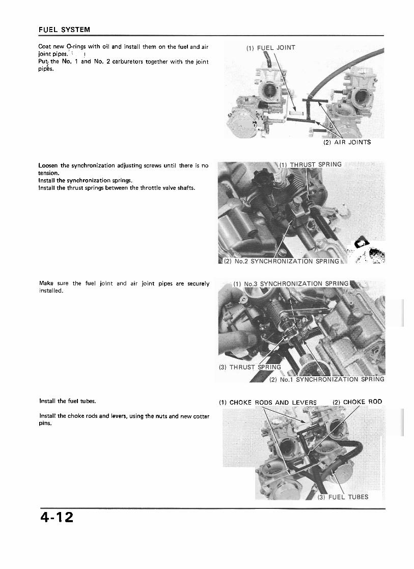
Coat new Orings with oil and install them on the fuel and air joint pipes. I
Put the No. 1 and No. 2 carburetors together with the joint pipes.
Loosen the synchronization adjusting screws until there is no tension. Install the synchronization springs. Install the thrust springs between the thronle valve shafts.
Make sure the fuel joint and air joint pipes are securely installed.
,., cl. ;'Ø
1 " . ,- ,
* X
(2) AIR JOINTS
.. - w... : , .>$@@q >v .< ' .., > ...*
Install the fuel tubes. (1) CHOKE RODS AND LEVERS (2) CHOKE ROD
Install the choke rods and levers, using the nuts and new cotter pins.
4-1 2
FUEL SYSTEM
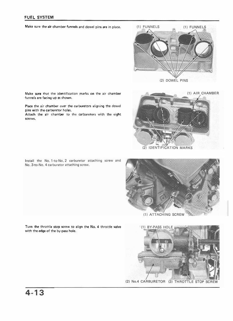
Make sure the air charnber funnels and dowel pins are in place.
Make sure that the identification marks on the air chamber funnels are facing up as shown.
Place the air charnber over the carburetors aligning the dowel pins with the carburetor holes. Attach the air charnber to the carburetors with the eight screws.
Turn the throttle stop screw to align the No. 4 throttle valve with the edge of the by-pass hole.
FUEL SYSTEM 1
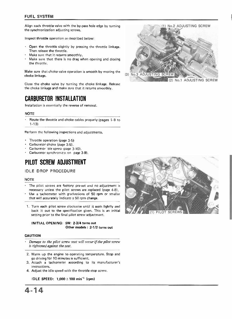
Align each throttle valve with the by-pass hole edge by turning the synchronization adjusting screws.
Inspect throttle operation as described below:
Open the throttle slightly by pressing the throttle linkage. Then release the throttle. Make sure that it returns smoothly. Make sure that there is no drag when opening and closing the throttle.
Make sure that choke valve operation is smooth by moving the choke linkage.
Close the choke valve by turning the choke linkage. Release the choke linkage and make sure that i t returns smoothly.
CARBURETOR INSTALLATION Installation is essentially the reverse of removal.
NOTE
Route the throttle and choke cables properly (pages 1-9 to 1-13)
Perform the following inspections and adjustments.
. Throttle operation (page 3-5) Carburetor choke (page 3-5). Carhureror 'Ole speeo (page 3-10). Carhuretor synchroniz31 on page 3-91,
PILOT SCREW ADJUSTMENT IDLE DROP PROCEDURE
NOTE
The pilot screws are factory pre-set and no adjustment is necessary unless the pilot screws are replaced (page 4-8). Use a tachometer with graduations of 50 rpm or smaller that will accurately indicate a 50 rprn change.
1. Turn each pilot screw clockwise until i t seats lightly and back it out to the specification given. This is an initial setting prior to the final pilot screw adjustment.
INITIAL OPENING: SW: 2314 turns out Other rnodels : 2-1/2 turns out
CAUTION
Dnmge to the pilot screw sent will occur if the pilot screw is tightened against the seat.
2. Warm up the engine to operating temperature. Stop and go driving for 10 minutes is sufficient.
3. Attach a tachometer according to i t s manufacturer's instructions.
4. Adjust the idle speed with the throttle stop screw.
IDLE SPEED: 1,000 + 100 min-' (rprnl
FUEL SYSTEM
5. Turn each pilot screw 112 turn out from the initial setting. 6. If the engine speed increases by 50 rpm or more, turn
each pilot screw out by successive 112 turn until engine speed drops by 50 rpm or less.
7. Adjust the idle speed with the throttle stop screw. 8. Turn the No. 1 carburetor pilot screw in until the engine
speed drops 50 rpm. 9. Turn the No. 1 carburetor pilot screw 1 turn out from the
position obtained in step 8. 10. Adjust the idle speed with the throttle stop screw. 11. Perform steps 8, 9 and 10 for the No. 2, 3 and 4
carburetor pilot screws.
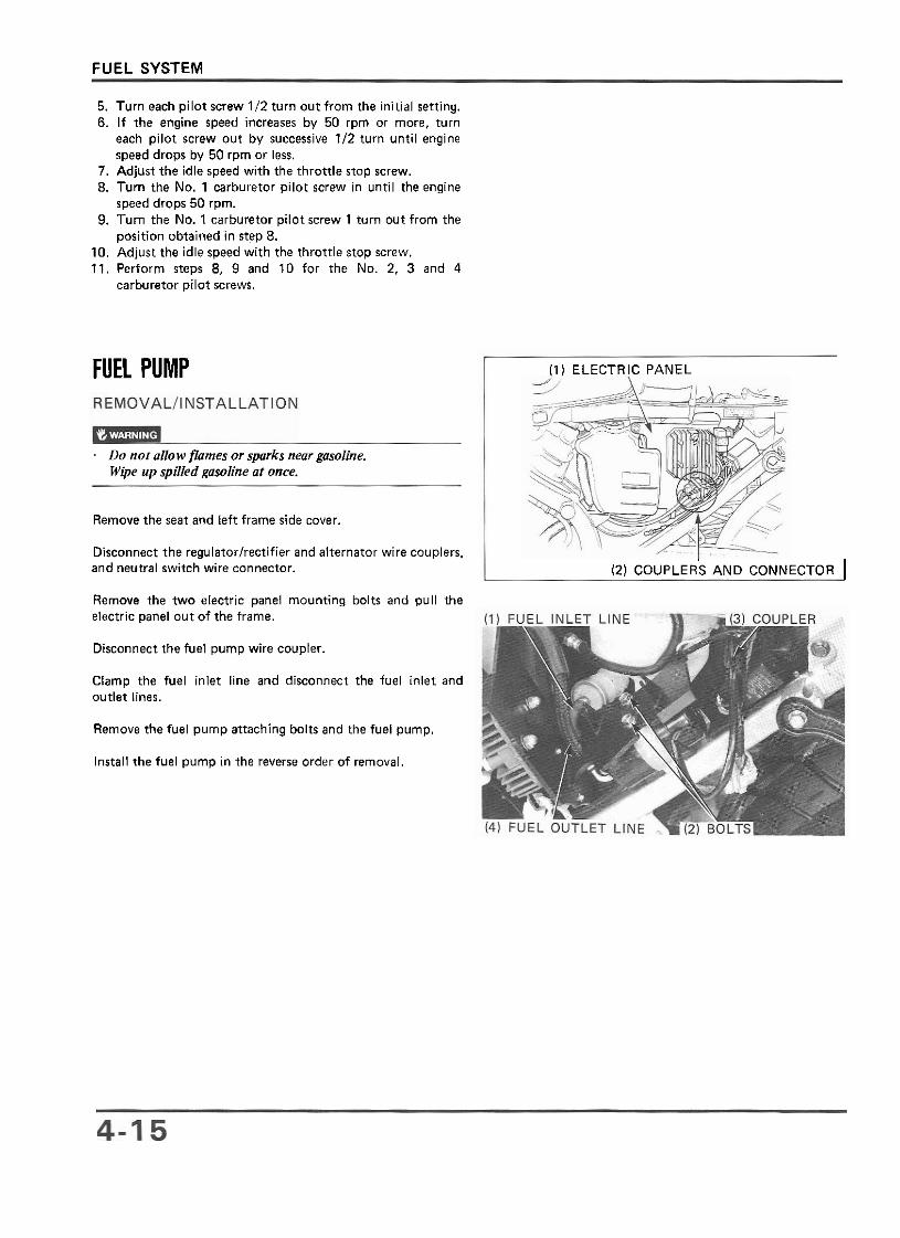
FUEL PUMP
Do not allow jiarnes or sparks near gosoline. Wipe up spilled gasoline at once.
Remove the seat and left frame side cover.
Disconnect the regulatorlrectifier and alternator wire couplers,
(1) ELECTRIC PANEL
electric panel out of the frame.
and neutral switch wire connector.
Disconnect the fuel pump wire coupler.
(2) COUPLER'S AND CONNECTOR I
Clamp the fuel inlet line and disconnect the fuel inlet outlet lines.
Remove the two electric panel mounting bolts and pull the
Remove the fuel pump attaching bolts and the fuel pump.
Install the fuel pump in the reverse order of removal.
and