fujitsu local area network...
TRANSCRIPT
Installation Guide - English
Fujitsu Local Area Network Adapter
Fujitsu PLAN EP OCe14102 2x 10Gb BASE-T Hardware and Software Installation Guide
Edition September 2015
Comments… Suggestions… Corrections…
The User Documentation Department would like to know your opinion of this manual. Your feedback helps us optimize our documentation to suit your individual needs.
Feel free to send us your comments by e-mail to [email protected].
Certified documentation according to DIN EN ISO 9001:2008
To ensure a consistently high quality standard and user-friendliness, this documentation was created to meet the regulations of a quality management system which complies with the requirements of the standard DIN EN ISO 9001:2008.
cognitas. Gesellschaft für Technik-Dokumentation mbH www.cognitas.de
Copyright and Trademarks Copyright © 2015 Fujitsu Technology Solutions GmbH.
All rights reserved. Delivery subject to availability; right of technical modifications reserved..
All hardware and software names used are trademarks of their respective manufacturers.
Table of Contents
PLAN EP OCe14102 2x 10Gb BASE-T Page 3
Table of Contents
1. Introduction .......................................................................................................................... 4
Major Features ............................................................................................................................................... 4
Prerequisites ................................................................................................................................................... 5
Adapter Identification ..................................................................................................................................... 6
2. Hardware Installation ............................................................................................................ 7
Preparing the Adapter for Installation ............................................................................................................ 7
Installing the Adapter ...................................................................................................................................... 8
Interconnect Cabling Distances ...................................................................................................................... 8
Applying Power ............................................................................................................................................... 8
Viewing the LEDs ............................................................................................................................................. 8
3. Attaching Devices to the Adapter ........................................................................................ 10
Connecting Devices to Adapter Using a UTP or CAT Cable .................................................................10
4. Software Installation ........................................................................................................... 11
First installation ...................................................................................................................................11
Update and manual installation ...........................................................................................................11
Emulex Management Utility OneCommand Manager (OCM) .............................................................11
Enabling or Disabling the Secure Firmware Feature ...........................................................................11
5. References .......................................................................................................................... 13
Specifications ................................................................................................................................................13
FCC and Regulatory Notices ..........................................................................................................................15
Declarations of Conformity ...........................................................................................................................17
PLAN EP OCe14102 2x 10Gb BASE-T Page 4
1. Introduction Adapter Identification
1. Introduction
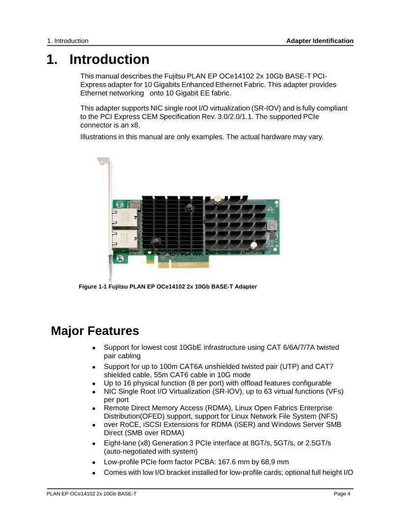
This manual describes the Fujitsu PLAN EP OCe14102 2x 10Gb BASE-T PCI-Express adapter for 10 Gigabits Enhanced Ethernet Fabric. This adapter provides Ethernet networking onto 10 Gigabit EE fabric.
This adapter supports NIC single root I/O virtualization (SR-IOV) and is fully compliant to the PCI Express CEM Specification Rev. 3.0/2.0/1.1. The supported PCIe connector is an x8.
Illustrations in this manual are only examples. The actual hardware may vary.
Figure 1-1 Fujitsu PLAN EP OCe14102 2x 10Gb BASE-T Adapter
Major Features
Support for lowest cost 10GbE infrastructure using CAT 6/6A/7/7A twisted pair cabling
Support for up to 100m CAT6A unshielded twisted pair (UTP) and CAT7 shielded cable, 55m CAT6 cable in 10G mode
Up to 16 physical function (8 per port) with offload features configurable NIC Single Root I/O Virtualization (SR-IOV), up to 63 virtual functions (VFs)
per port Remote Direct Memory Access (RDMA), Linux Open Fabrics Enterprise
Distribution(OFED) support, support for Linux Network File System (NFS) over RoCE, iSCSI Extensions for RDMA (iSER) and Windows Server SMB
Direct (SMB over RDMA) Eight-lane (x8) Generation 3 PCIe interface at 8GT/s, 5GT/s, or 2.5GT/s
(auto-negotiated with system) Low-profile PCIe form factor PCBA: 167.6 mm by 68,9 mm Comes with low I/O bracket installed for low-profile cards; optional full height I/O
PLAN EP OCe14102 2x 10Gb BASE-T Page 5
1. Introduction Adapter Identification
bracket is included in lose delivery unit. Support for fully specified 10GBaseT or 1GBaseT speeds External volatile memory: 2Gb/4Gb DDR3 SDRAM technology On-board flash memory: The flash is 128Mbit with a SPI interface. The flash
contains the vital product data (VPD) and Boot BIOS images. You can update the flash with Emulex utilities.
Comprehensive array of NIC, operating system drivers, including support for Windows, Linux, and VMware
Parts and construction compliant to the European Union Directive of Restriction of Hazardous Substances (RoHS), and similar regulatory requirements for other countries.
Ethernet standards - IEEE 802.3an 10GBASE-T - IEEE 802-3ab 1000BASE-T - IEEE 802.1Q virtual LANs (VLAN) - IEEE 802.3-2012 Flow control with Pause frames - IEEE 802.1Qbg Edge Virtual Bridging - IEEE 802.1Qaz Enhanced Transmission Selection (ETS);
Data Center Bridging Capability Exchange (DCBX) - IEEE 802.1Qbb Priority Flow Control (PFC) - IEEE 802-1AX Link Aggregation/LACP - IEEE 802.1AB Link Layer Discovery Protocol (LLDP) - IEEE 802.1Qau Congestion Notification
Protocol-specific capabilities - NIC capabilities include:
- NDIS 5.2, 6.0, and 6.2-compliant Ethernet functionality - IPv4/IPv6 TCP, UDP checksum offload - IPv4/IPv6 Receive Side Scaling (RSS) - IPv4/IPv6 Large Receive Offload (LRO) - IPv4/IPv6 Large Send Offload (LSO) - Programmable MAC addresses - Up to 128 MAC/VLAN addresses - Support for hash-based multicast MAC address filters - Support for hash-based broadcast frame filters per port - VLAN insertion and extraction - Jumbo packet support up to 9000 bytes
Prerequisites
PCI Express 3.0/2.0/1.1 compliant systems: x8 lane at up to 8 Gb/s per lane.

PLAN EP OCe14102 2x 10Gb BASE-T Page 6
1. Introduction Adapter Identification
Adapter Identification
Each adapter ships with several numbers clearly marked on the board. Fujitsu recommends recording these numbers before installation.
IEEE address – a unique 64-bit identifier used for system configuration Serial number – assigned by Emulex and used when communicating with
Emulex
Note: The adapter has two IEEE addresses, one for each port
PLAN EP OCe14102 2x 10Gb BASE-T Page 7
2. Hardware Installation Applying Power
2. Hardware Installation
The PLAN EP OCe 14102 2x 10Gb Base-T has two RJ45 connectors The bracket is mounted to the Printed Circuit Board (PCB) via two (Phillips type head) SEM screws. The bracket can be separated from the PCB by removing the two screws.
Preparing the Adapter for Installation
Before installing the adapter, you should perform the following steps:
1. Turn off the computer and unplug it. 2. Remove the computer case.
Note: The adapter comes with a low-profile PCIe bracket installed. A low profile
bracket is included in the box with the adapter.
3. For the PLAN EP OCe14102 2x 10Gb Base-T adapter, if you want to change the bracket to a full height version, follow steps 4–9; otherwise, proceed to “Installing the Adapter” on page 8.
4. Observing Electrostatic Discharge (ESD) precautions, store the transceiver in an ESD-safe place.
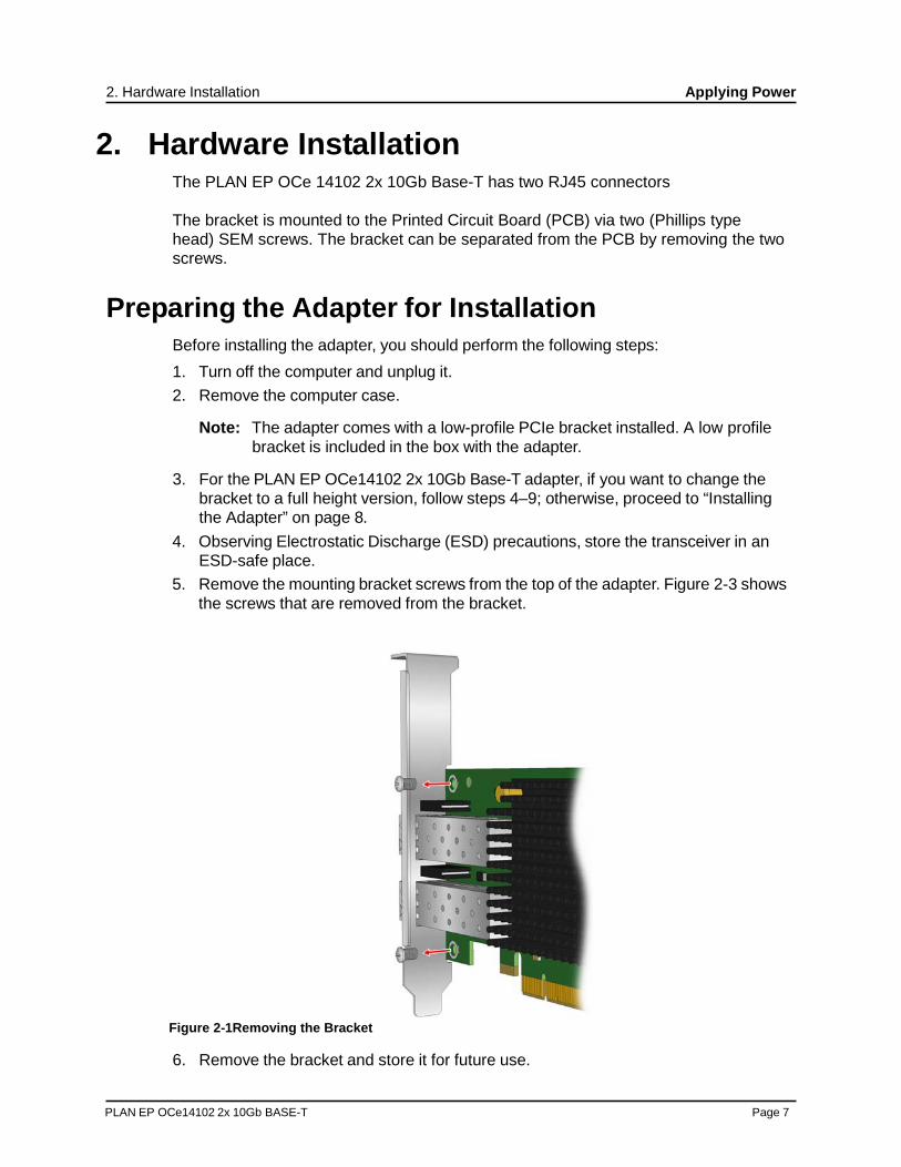
5. Remove the mounting bracket screws from the top of the adapter. Figure 2-3 shows the screws that are removed from the bracket.
Figure 2-1Removing the Bracket
6. Remove the bracket and store it for future use.
PLAN EP OCe14102 2x 10Gb BASE-T Page 8
2. Hardware Installation Applying Power
7. Align the new mounting bracket tabs with the holes in the adapter.
Note: Be careful not to push the bracket past the transceiver housing's grounding tabs. Ensure the light emitting diodes (LEDs) are properly aligned with the holes in the bracket.
8. Re-install the screws that attach the adapter to the bracket. 9. Push the bail back into place.
Installing the Adapter
To install the adapter:
1. Turn off and unplug the computer. 2. Remove the computer case. 3. Remove the blank panel from an empty PCIe bus slot. See “Preparing the Adapter
for Installation” on page 7 to change the brackets if needed. Otherwise, proceed to “Attaching Devices to the Adapter” on page 10.
4. Insert the adapter into an empty x8 or x16 PCIe bus slot. Press firmly until the adapter is seated. Note: Make sure that the adapter is in an appropriate PCIe slot that does not
interfere with other components or case to prevent damage to the adapter.
5. Secure the adapter's mounting bracket to the case with a panel screw or clip. 6. Replace the computer case and tighten the case screws.
The adapter is now installed in the server and is ready for device attachment.
Interconnect Cabling Distances
- Up to 100m on CAT 6A, CAT 7 in 10G mode - Up to 55m on CAT 6 in 10G mode - Up to 100m on CAT 5E (or higher category cable) in 1000BASE-T (1G) mode
Applying Power
To apply power:
1. Verify that the adapter is securely installed in the computer. 2. Verify that the correct device is attached. 3. Plug in and turn on the computer. 4. Observe the boot banner for Power On Self Test (POST) results.
Viewing the LEDs
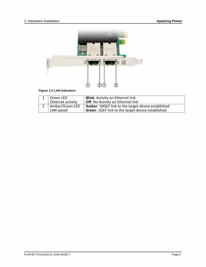
Each port connector has two LEDs: an amber/green LED and a green LED.
PLAN EP OCe14102 2x 10Gb BASE-T Page 9
2. Hardware Installation Applying Power
Figure 2-2 LAN Indicators
1 Green LED Ethernet activity
Blink: Activity on Ethernet link Off: No Activity on Ethernet link
2 Amber/Green LED LAN speed
Amber: 10GbT link to the target device established Green: 1GbT link to the target device established
PLAN EP OCe14102 2x 10Gb BASE-T Page 10
3. Software Installation
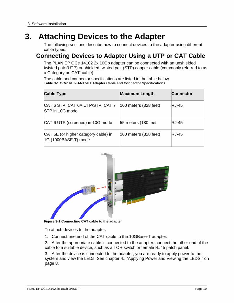
3. Attaching Devices to the Adapter The following sections describe how to connect devices to the adapter using different cable types.
Connecting Devices to Adapter Using a UTP or CAT Cable The PLAN EP OCe 14102 2x 10Gb adapter can be connected with an unshielded twisted pair (UTP) or shielded twisted pair (STP) copper cable (commonly referred to as a Category or 'CAT' cable). The cable and connector specifications are listed in the table below. Table 3-1 OCe14102B-NT/-UT Adapter Cable and Connector Specifications
Cable Type Maximum Length Connector
CAT 6 STP, CAT 6A UTP/STP, CAT 7 STP in 10G mode
100 meters (328 feet) RJ-45
CAT 6 UTP (screened) in 10G mode 55 meters (180 feet RJ-45
CAT 5E (or higher category cable) in 1G (1000BASE-T) mode
100 meters (328 feet) RJ-45
Figure 3-1 Connecting CAT cable to the adapter
To attach devices to the adapter:
1. Connect one end of the CAT cable to the 10GBase-T adapter. 2. After the appropriate cable is connected to the adapter, connect the other end of the cable to a suitable device, such as a TOR switch or female RJ45 patch panel. 3. After the device is connected to the adapter, you are ready to apply power to the system and view the LEDs. See chapter 4., “Applying Power and Viewing the LEDS,” on page 8.

PLAN EP OCe14102 2x 10Gb BASE-T Page 11
3. Software Installation
4. Software Installation
First installation
For the first installation please use the ServerView Installation Manager (SVIM). For detailed information please refer to the ServerView Installation Manager manual available on the web. You access the start page of the online documentation via the following link:
http://manuals.ts.fujitsu.com In the selection list on the left, select x86 Servers. On the right, click PRIMERGY ServerView Links under Selected documents.
Update and manual installation
Fujitsu provides necessary driver and utilities on the web via:
http://support.ts.fujitsu.com/productselect.asp?lng=com&Level1=20966&lnid=3
Emulex Management Utility OneCommand Manager (OCM)
For Windows operating systems the Emulex Management Utility OneCommand Manager (OCM) will be installed by SVIM automatically.
Under Linux operating systems a manual installation is necessary. Link to:
http://support.ts.fujitsu.com/productselect.asp?lng=com&Level1=20966&lnid=3
Enabling or Disabling the Secure Firmware Feature
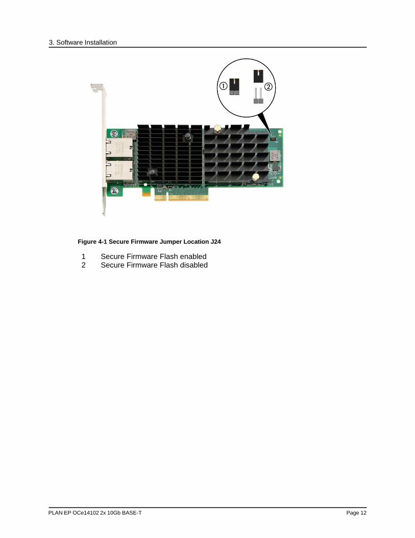
The PLAN EP OCe 14102 2x 10GB Base-T adapter has a jumper (J24) that enables or disables the Secure Firmware feature as required.
To ensure that the firmware on this adapter cannot be changed offline (using an ISO flash file), leave the jumper block installed on the relevant jumper pins (Secure Firmware enabled). To allow offline firmware updates on this adapter, remove the jumper block from the pins (Secure Firmware disabled); the jumper must be replaced after the offline update is completed. To update the firmware using a tool such as the OneCommand Manager application, boot utilities, or Elxflash utilities, there is no need to remove the jumper – the Secure Firmware feature can remain enabled. The following illustrations,
Figure 4-1 on page 12 shows the locations of the Secure Firmware jumper J24.
PLAN EP OCe14102 2x 10Gb BASE-T Page 12
3. Software Installation
Figure 4-1 Secure Firmware Jumper Location J24
1 Secure Firmware Flash enabled 2 Secure Firmware Flash disabled

PLAN EP OCe14102 2x 10Gb BASE-T Page 13
4. References Specifications
5. References
Specifications
Table 5-1 PLAN EP OCe14102 BASE-T Adapter Specifications
Parameter
Range
Physical Dimensions Low-profile form factor, 6.600 inches by 2.713 inches, and accommodates both the full-height and low-profile bracket.
Power Requirements PLAN EP OCe14102 BASE-T adapter: Typical power requirements
10Gb/s – 10/30m CAT6A cables 3.3 V: 5.153W 12 V: 10.865W Total: 16.018W 10Gb/s - 100m CAT6A cables 3.3 V: 5.356W 12 V: 11.033W Total: 16.389W 1Gb/s - 10/30m CAT6A cables 3.3 V: 5.004W 12 V: 6.483W Total: 11.487W 1Gb/s - 100m CAT6A cables 3.3 V: 5.032W 12 V: 6.525W Total: 11.557W
Airflow 200 lf/min (minimum)
Temperature 0°C to 55°C (operating) -40°C to 70°C (non-operating)
Note: Operating the adapter in higher temperatures and/or lower air flow may result in premature failures.
Humidity Operating: 10% to 90% RH, non-condensing, 22°C wet bulb Non-operating: 5% to 95% RH, non-condensing, 22°C wet bulb

PLAN EP OCe14102 2x 10Gb BASE-T Page 14
4. References Specifications
Agency Approvals for PLAN EP OCe14102 BASE-T adapter
• UL recognized to UL60950-1 2nd Edition • cUR recognized to CSA 22.2, No. 60950-1-07 • TUV certified to EN60950-1:2006 +A11 +A1 +A12 • FCC Rules, Part 15, Subpart B, Class A • CB Report and Certificate to IEC 60950:2005+A1 • Industry Canada, ICES-003, Class A • EMC Directive 2004/108/EC (CE Mark)
EN55022:2010, Class A EN55024:2010
• Australian EMC Framework (C-Tick Mark) AS/NZS CISPR22:2009 +A1, Class A
• Japan VCCI, Class A • Korea MSIP, Class A (KN22 /KN24) referencing latest MSIP and
RRL notices • BSMI Class A, consisting of CNS 13438:2006 (complete edition) • RoHS Compliant (Directive 2011/65/EU) • China RoHS compliant
Vibration, peak acceleration 0.25g (5 Hz to 500 Hz) (Sweep Rate = 1 octave/min.)

PLAN EP OCe14102 2x 10Gb BASE-T Page 15
4. References FCC and Regulatory Notices
FCC and Regulatory Notices
OCe14000-series Adapters
This device complies with Part 15 of the FCC Rules. Operation is subject to the following two conditions: (1) This device may not cause harmful interference, and (2) this device must accept any interference received, including interference that may cause undesired operation.
Responsible Party:
Jeff Benck, President and Chief Executive Officer
Emulex Corporation (714) 662-5600
3333 Susan St. Costa Mesa, CA. 92626 USA
Note: This equipment has been tested and found to comply with the limits for a Class A digital device, pursuant to part 15 of the FCC Rules. These limits are designed to provide reasonable protection against harmful interference when the equipment is operated in a commercial environment. This equipment generates, uses, and can radiate radio frequency energy and, if not installed and used in accordance with the instruction manual, may cause harmful interference to radio communications. Operation of this equipment in a residential area is likely to cause harmful interference in which case the user will be required to correct the interference at his own expense. The reader is cautioned that changes or modifications made to the equipment not expressly approved by Emulex could void the user's authority to operate this equipment. The above statement applies to products marketed in the USA.
This class A digital apparatus meets all requirements of the Industry Canada (IC) Interference - Causing Equipment Standard (ICES-003). Cet appareil numérique de la classe A respecte toutes les exigences du règlement sur le matériel brouilleur du Canada. CAN ICES-3 (A)/ NMB-3 (A)
Notice for Japan and Translations (VCCI)
Translation:
This is a Class A product. If this equipment is used in a domestic environment, radio interference may occur, in which case, the user may be required to take corrective action. VCCI—A.

PLAN EP OCe14102 2x 10Gb BASE-T Page 16
4. References FCC and Regulatory Notices
Notice for Taiwan and Translations (BSMI)
Translation:
This equipment is a Class A ITE, and operation of this equipment in a residential area is likely to cause harmful interference, in which case users will be required to correct the interference at their own expense.
Notice for South Korea and Translations (KCC)
Translation:
Sellers and users of this equipment take note that this equipment is EMC approved for Class A industrial use, and as such is not intended for residential use.

PLAN EP OCe14102 2x 10Gb BASE-T Page 17
4. References Laser Safety Notice
Declarations of Conformity
PLAN EP OCe 14102 2x 10Gb Base-T Adapter
This equipment complies with CISPR22/EN55022 Class A.
WARNING: This is a class A product. In a domestic environment, this product may cause radio interference requiring the user to take adequate measures.
Note: Changes or modifications not expressly approved by Emulex Corporation,
including the use of non-Emulex approved optical transceivers, could void the user's authority to operate this equipment.