fully automatic electric jigging reel - oilwind gb-brugarvejl.pdf · 3 summary of the operation the...
TRANSCRIPT

USER`S MANUALUSER`S MANUAL
TYPE: 03-16TYPE: 03-16
FULLY AUTOMATICELECTRICJIGGING REEL
FULLY AUTOMATICELECTRICJIGGING REEL

1
TYPE:
SERIAL NO.:
PART NO.:
YEAR:
KEYPAD NO.:
Sellers Guaranty:
Guaranty:The guaranty covers the Electric Computerised Jigging Machine OILWIND type 03-16. The Seller will provide a 24 months guarantee from date of purchase (stated below), covering the product's mechanical functions, as described in this Users Manual.
Condition:Guarantee work, during the guarantee period, must only be carried out by the Seller's own service specialists, or by a service specialist appointed by the Seller. For parts, repaired or replaced, during the guarantee period, the Seller provides the same guarantee as above.It is the Owner's responsibility to cover the transport costs, if any.The Seller takes no responsibility, if the product is damaged or faulty due to transport, handling, lack of regular maintenance, wrong installation and/or connecting or if the Owner has made any alternations or changes of the original product, or has been using the product to any purpose, apart from jig fishery.The Seller can neither accept any responsibility for any damage or fault caused by bad weather or any other nature reason.It is the Buyers responsibility to maintain the product and to repair and replace parts to the operational wear and tear.
The Sellers responsibility starts from:Date, signature and stamp

2
Seller´s Guaranty
Summary.........................................................................Before starting.................................................................The computer..................................................................Description of the functions.............................................Pre-chosen values (standard program)...........................Mounting onboard the vessel..........................................Electric connection..........................................................
Maintenance:Weight sensing arm....................................................Replacing of the fuse..................................................Replacing of the print boards......................................Humidity bag...............................................................
Adjustment excamples:Standard program.......................................................The search mode........................................................The adjust depth mode...............................................The jig pause mode....................................................Mode for Squid/Mackerel fishery................................
Mounting brackets...........................................................
Technical Information......................................................
1
3456
171819
20212223
2526272829
33
34
TABLE OF CONTENTS:

3
Summary of the Operation
The Jigging Machine is electrically driven and the fishing functions are computer controlled.
The operation of the machine is simple:
Switch-on the machine, press the (DOWN) button. The line pays out until the sinker reach the
bottom, and the Machine starts fishing.
The Machine is programmed with all fishing functions pre-set, ready to start fishing (please see instruction regarding adjusting the weight, page 14).
Above mentioned standard program is for bottom fishing. Fig. 10 on page 25 shows the nature of this fishery.
The standard program can be adjusted to your requirements. Adjustments can be saved for future use as your own program, but you can always return to the original standard program.
The computer is inside the box on top of the machine. On the computer box is the keypad with:
Display, showing the computers different values, adjustments and information to the user
Also there are 10 buttons for adjusting and controlling the machine, and a whistle giving information to the user by sounds.
4
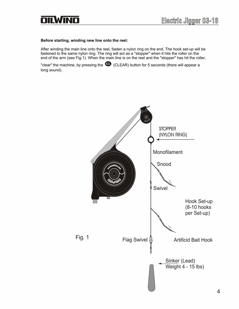
Before starting, winding new line onto the reel:
After winding the main line onto the reel, fasten a nylon ring on the end. The hook set-up will be fastened to the same nylon ring. The ring will act as a "stopper" when it hits the roller on the end of the arm (see Fig.1). When the main line is on the reel and the "stopper" has hit the roller,
"clear" the machine, by pressing the (CLEAR) button for 5 seconds (there will appear a
long sound).
STOPPER(NYLON RING)
Fig. 1
Hook Set-up(8-10 hooksper Set-up)
Sinker (Lead)Weight 4 - 15 lbs)
Swivel
Monofilament
Flag Swivel
Snood
Artificid Bait Hook
5
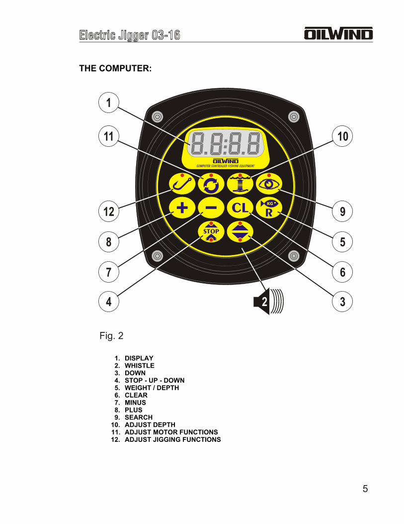
THE COMPUTER:
1. DISPLAY2. WHISTLE3. DOWN4. STOP - UP - DOWN5. WEIGHT / DEPTH6. CLEAR7. MINUS8. PLUS9. SEARCH
10. ADJUST DEPTH11. ADJUST MOTOR FUNCTIONS12. ADJUST JIGGING FUNCTIONS
1
11 10
12 9
8 5
7 6
4 32
Fig. 2
6
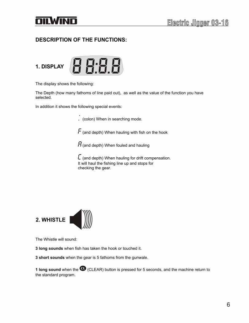
The display shows the following:
The Depth (how many fathoms of line paid out), as well as the value of the function you have selected.
In addition it shows the following special events:
(colon) When in searching mode.
(and depth) When hauling with fish on the hook
(and depth) When fouled and hauling
(and depth) When hauling for drift compensation.
It will haul the fishing line up and stops for checking the gear.
The Whistle will sound:
3 long sounds when fish has taken the hook or touched it.
3 short sounds when the gear is 5 fathoms from the gunwale.
1 long sound when the (CLEAR) button is pressed for 5 seconds, and the machine return to
the standard program.
1. DISPLAY
DESCRIPTION OF THE FUNCTIONS:
2. WHISTLE
7
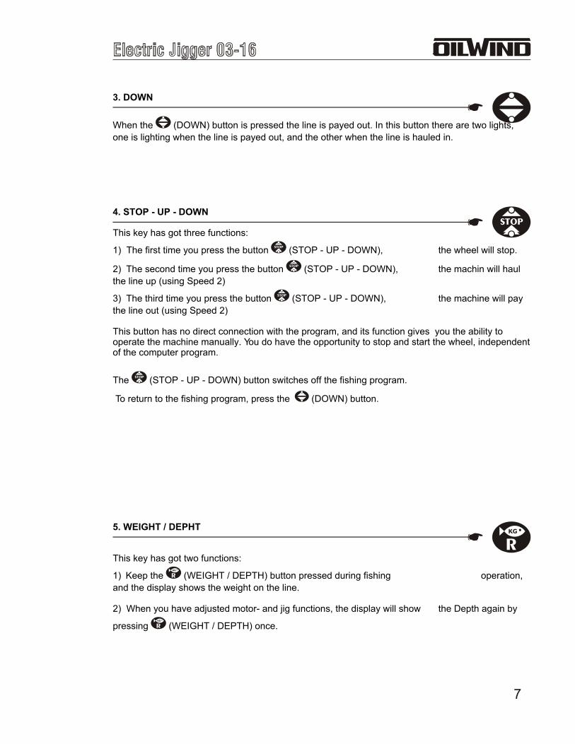
3. DOWN
When the (DOWN) button is pressed the line is payed out. In this button there are two lights,
one is lighting when the line is payed out, and the other when the line is hauled in.
4. STOP - UP - DOWN
This key has got three functions:
1) The first time you press the button (STOP - UP - DOWN), the wheel will stop.
2) The second time you press the button (STOP - UP - DOWN), the machin will haul
the line up (using Speed 2)
3) The third time you press the button (STOP - UP - DOWN), the machine will pay
the line out (using Speed 2)
This button has no direct connection with the program, and its function gives you the ability to operate the machine manually. You do have the opportunity to stop and start the wheel, independent of the computer program.
The (STOP - UP - DOWN) button switches off the fishing program.
To return to the fishing program, press the (DOWN) button.
5. WEIGHT / DEPHT
This key has got two functions:
1) Keep the (WEIGHT / DEPTH) button pressed during fishing operation,
and the display shows the weight on the line.
2) When you have adjusted motor- and jig functions, the display will show the Depth again by
pressing (WEIGHT / DEPTH) once.
8
6. CLEAR
1) Press the button (CLEAR) once - the actual value of the individual function
adjusted, returns to the value in the standard programme.
2) Keep the button (CLEAR) pressed for five seconds (the whistle will give 1 long
sound) - all functions will return to the values in the standard programme. Apart from the above mentioned functions, the button is used to Clear the ADJUST DEPHT
( ) function (please see Adjust Depth on page 10).
This button has got two functions, to be used during "Adjust Motor" and "Adjust Jig":
7. MINUS
Press the button to reduce the value you want to adjust.
8. PLUS
Press the button to increase the value you want to adjust.
9
2) Searching for fish from a pre-set depth:
Press the (ADJUST DEPTH) button (the light start flashing), and then adjust your
depth by using the (PLUS) or (MINUS) buttons, Then press the (SEARCH)
button followed by the (DOWN) button, and the machine will pay-out the line to the
pre-set depth and starts searching (from adjusted depth to adjusted Search Range).
To stop searching, just press the buttons as follows: (ADJUST DEPTH),
(CLEAR), (SEARCH), and (DOWN).
9. SEARCH
1) Searching for fish from the bottom:
Press the (SEARCH) button (the light starts flashing) and then press the (DOWN).
The display shows a (colon), and the (SEARCH) botton lights. The Machine will
start to search for fish from the bottom and upwards. The Search mode operates per the current jig numbers and jig travel values and will move the line upwards until it has reached the value adjusted as "Search Range". Then the machine will pay-out the line to the bottom, and repeat the searching (please see further instructions in "Jig Functions", 7. "Search Range"). In the Standard Program the value of the Search Range" is 40, the machine will search up to 40 fathoms from the bottom or the starting point of search. This can be adjusted as to your own requirements.
To stop searching, just press the (SEARCH) button and then the
(DOWN).
The Search function has got the following two options:
10
10. ADJUST DEPTH
This button has got two functions:
1) The machine can be adjusted to fish at a certain depth.
Press the (ADJUST DEPTH) button and adjust the preferred depth with the (PLUS)
or (MINUS) button. Press the (DOWN) button and the machine starts fishing at the
pre-set depth (the buttons light is on as the machine is fishing at the pre-set depth).
To stop fishing from the pre-set depth, just press the buttons as follows: (ADJUST
DEPTH), (CLEAR) and (DOWN).
2) The machine can find the depth where the last fish was caught.
If the machine has caught a fish midwater, the machine will register the depth, and you can start fishing at this depth by:
Press the (ADJUST DEPTH) botton (the light will start flashing) and the display will
show the depth where the last fish was caught.
Then press the (DOWN) button, and the machine will pay out the line
to the depth where he latest fish was caught, and start fishing (the button light is on).
To stop fishing from the pre-set depth, just press the buttons as follows: (ADJUST
DEPTH), (CLEAR) and (DOWN).

11
THE (ADJUST MOTOR) AND (ADJUST JIG) MODES DO HAVE SEVERAL SUB-FUNCTIONS.
The functions are listed on top of the machine (fig. 3) with a number and name for the different
sub-functions for (ADJUST MOTOR) and (ADJUST JIG). To select a function, press the
button as many times as necessary to reach the desired function.
The value of the functions can then be adjusted by the (PLUS),
(MINUS) or (CLEAR) buttons.
When the ADJUST MOTOR or ADJUST Jig modes are activated, the button light is on and while the adjustments are made, the light will flash.
Fig. 3
JIG SPEED UPBITE SPEEDBITE TIMESPEED 1SPEED 2MAX. PULLMIN. PULLTANGLINGJIG SPEED DOWN
WEIGHTDIST. FROM BTM.JIG TRAVELJIG NUMBERDRIFT COMP.PROGRAMME 0-1WAVE COMP.SEARCH RANGEJIG PAUSE
TANGLINGDRIFT COMP.FISHSEARCHING
12
11. ADJUST MOTOR:
Adjusting the MOTOR functions:
Examples of adjusting JIG SPEED
Press the (ADJUST MOTOR) button. Press as many times as necessary to get the display to
show and a value (the button light is on). Adjust the value with the (PLUS) , (MINUS) or
(CLEAR) button (the light starts flashing). To get the adjustment accepted, press again the (ADJUST MOTOR). The light stops flashing.
To activate the new program press the (DOWN) button.
By pressing the (WEIGHT - DEPTH) button, the display shows the depth again (the (ADJUST MOTOR) button light is off).
0: JIG SPEED UP
The display shows: and a figure.This figure shows the adjusted Jig Speed when the line is hauled (when in jigging mode). The figure is the percentage of the maximum possible Jig Speed.
1: BITE SPEED
The display shows: and a figure.
This figure shows the adjusted Bite Speed. The Bite Speed is the hauling speed the first moment after a fish is caught. Bite Speed is used during the Bite Time. The figure is the percentage of the maximum possible Bite Speed.
2: BITE TIME
The display shows: and a figure.
This figure shows the adjusted Bite Time. The Bite Time is the period the Bite Speed shall last. The value is in seconds.
3: SPEED 1
The display shows: and a figure.
This figure shows the adjusted Speed 1, or revulutions per minute. The Speed 1 is the hauling speed after the Bite Time. The figure is the percentage of the maximum possible speed the machine will be hauling at. The value is the percentage of the maximum possible revolutions per minute..
13
4: SPEED 2
The display shows: and a figure.
This figure is the programmed speed 2, it is revolutions per minute (rpm). Speed 2 is used when
activating the (STOP-UP-DOWN) button. The figure is a percentage of maximum rpm.
5: MAXIMUM PULLING POWER.
The display shows: and a figure.
This figure is the percentage of maximum possible pulling power the machine is pulling at, when pulling with maximum force.
6: MINIMUM PULLING POWER.
The display shows: and a figure.
This figure is the percentage of maximum possible pulling power the machine is pulling at, when pulling with minimum force.When the machine is sensing the first bite, it starts pulling at Minimum Pulling Power. As the machine is sensing additional bites, it will auto-matically increase the Pulling Power and adjust the speed. This results in a minimising of power consumption, and the pull and speed will increase until the machine has reached the programmed values for MAXIMUM PULLING POWER and SPEED 1.
7: TANGLING
The display shows: and a figure.
This function is used to adjust the machine's sensitivity for registration of tangling of the fishing gear. The pre-set value is 4,5. A lower value means more sensitive and a higher value the opposite.This value is not required to be adjusted under normal conditions.
8: JIG SPEED DOWN
The display shows: and a figure.
This figure shows the adjusted Jig Speed when the line is payed out (when in jigging mode). The figure is the percentage of the maximum possible Jig Speed.
14
0: WEIGHT
The displays shows: and a figure.
This figure is the limit (weight) to cross, for the mode to sense a bite and start reel in the line.
Guidance to adjust the weight.Adjusting the limit (weight) is essential for the way the machine is sensing fish - a low value means a more sensitive registration (smaller weight of fish will be registered) and a high value means a less sensitive registration (larger weight of fish will be registered).
Adjusting the limit (weight) is also essential for compensation of the weight of the gear (line, hooks, sinker), as the weight of the gear will vary depending of depth and weather conditions.
Guidance to adjust for gear compensation.
The line and gear has to be in the water without fish on the hooks, then press the
(WEIGHT - DEPTH) button. The display shows then the weight of the line and gear.
Then adjust the limit (weight) (see above), based on the weight of the line and gear.
The weight shall be adjusted to a weight higher than the weight of the line and gear, depending on how sensitive you choose the machine to be.
12. ADJUST JIGGING FUNCTIONS
Adjusting the JIG functions:
Examples of adjusting WEIGHT
Press the (ADJUST JIG) button. Press as many times as necessary to get the display
to show and a value (the button light is on). Adjust the value with the (PLUS),
(MINUS) or (CLEAR) button (the button light will start flashing). To get the
adjustment accepted, press again the (ADJUST JIG) The button light will stop
flashing.
By pressing the (WEIGHT - DEPTH). button, the display shows the depth again (the
(ADJUST JIG) button light is off).
15
1: HEIGHT FROM BOTTOM
The display shows: and a figure.
This figure is the distance from the bottom (in fathoms) the machine will haul the gear before commence jigging.
2: JIG TRAVEL
The display shows: and a figure.
This value is the jig travel in fathoms.
3: JIG NUMBER
The display shows: and a figure.
This figure is the number of times the reel jig before searching for the bottom again.
4: DRIFT COMPENSATION
The display shows: and a figure
Depending on tide and weather conditions, the line can angle away from the fishing boat. This can affect the efficiency of the fishing. To compensate for this, the machine has the function DRIFT COMPENSATION. The figure indicates the number of jigs before the machine is hauling the gear to the gunwale. To be adjusted to the weather conditions. Use a lower value in bad weather and current conditions. This function also is for controlling the gear, and if there should be fish on the hooks, not registered by the machine.
5: PROGRAMME 0-1
The display shows: and a figure.
This figure can adjusted as 0 or 1.If the figure is adjusted to 0 (standard), the machine will operate as described before as to the standard program. If the figure is adjusted to 1, the machine will fish without any stops. The machine will pay out the line, and haul up again to the gunwale immediately. Here it stops for some seconds, and will repeat the operation.This fishing method is used for e.g. squid and mackerel fishing.
16
6: WAVE COMPENSATION
The display shows: and a figure.
The standard figure for Wave Compensation is 0, and in normal conditions it is not necessary to adjust this figure. If the vessel has heavy moves in rough sea, the machine may falsely sense the sinker has touched the bottom, so the value may need to be adjusted. If the vessel is rolling faster than the line is payed out, the machine will sense it as the sinker has touched the bottom, and will start fishing before the sinker has reached the bottom. Under these conditions, the WAVE COMPENSATION should be increased.
7: SEARCH RANGE
The display shows: and a figure.
This figure indicates how many fathoms from the surface, or pre-set depth, the machine is
adjusted to commence search (see the (SEARCH) button on page 9).
8: JIG PAUSE
The display showes and a figure.
This figure indicates in seconds the pause between jigging period.
17
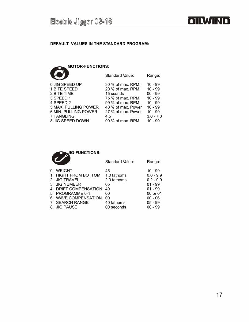
DEFAULT VALUES IN THE STANDARD PROGRAM:
MOTOR-FUNCTIONS:
Standard Value: Range:
0 JIG SPEED UP 30 % of max. RPM. 10 - 991 BITE SPEED 20 % of max. RPM. 10 - 992 BITE TIME 15 sconds 00 - 993 SPEED 1 75 % of max. RPM. 10 - 994 SPEED 2 99 % of max. RPM. 10 - 995 MAX. PULLING POWER 40 % of max. Power 10 - 996 MIN. PULLING POWER 27 % of max. Power 10 - 997 TANGLING 4.5 3.0 - 7.08 JIG SPEED DOWN 90 % of max. RPM 10 - 99
JIG-FUNCTIONS:
Standard Value: Range:
0 WEIGHT 45 10 - 991 HIGHT FROM BOTTOM 1.0 fathoms 0.0 - 9.92 JIG TRAVEL 2.0 fathoms 0.2 - 9.93 JIG NUMBER 05 01 - 994 DRIFT COMPENSATION 40 01 - 995 PROGRAMME 0-1 00 00 or 016 WAVE COMPENSATION 00 00 - 067 SEARCH RANGE 40 fathoms 05 - 998 JIG PAUSE 00 seconds 00 - 99
18
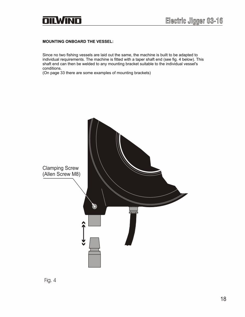
Clamping Screw(Allen Screw M8)
Fig. 4
MOUNTING ONBOARD THE VESSEL:
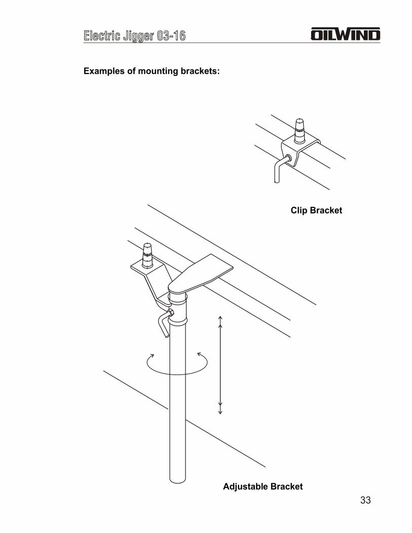
Since no two fishing vessels are laid out the same, the machine is built to be adapted to individual requirements. The machine is fitted with a taper shaft end (see fig. 4 below). This shaft end can then be welded to any mounting bracket suitable to the individual vessel's conditions.(On page 33 there are some examples of mounting brackets)
19
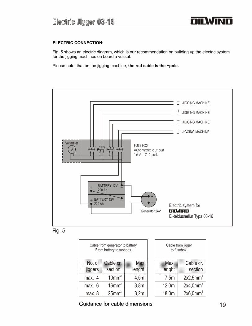
ELECTRIC CONNECTION:
Fig. 5 shows an electric diagram, which is our recommendation on building up the electric system for the jigging machines on board a vessel.
Please note, that on the jigging machine, the red cable is the +pole.
+
+
+
+
-
-
-
-
Electric system for
El-teldusnellur Typa 03-16
-
-
+
+ +
-
V
JIGGING MACHINE
FUSEBOXAutomatic cut out16 A - C 2 pol.
BATTERY 12V220 Ah
BATTERY 12V220 Ah
JIGGING MACHINE
JIGGING MACHINE
JIGGING MACHINE
Generator 24V
Voltmeter
Cable from generator to battery From battery to fusebox.
max. 4 4,5m210mm
No. ofjiggers
Maxlenght
Cable cr. section.
max. 6 3,8m216mm
max. 8 3,2m225mm
Cable from jiggerto fusebox.
Max.lenght
Cable cr.section
7,5m 22x2,5mm
12,0m
18,0m
22x4,0mm22x6,0mm
Guidance for cable dimensions
Fig. 5

20
MAINTENANCE:
Weight sensing arm:
For the machine it is of great importance, that the weight sensing arm's function is smooth and frictionless. Therefore please be very careful, that there is no dirt or corrosion on the weight sensing arm's cylinder(see fig. 6 below). The cylinder needs to be coated in light oil frequently. Please make it a rule, that you check this before leaving for the fishing grounds.
Weight sensing arm
Cylinder
Fig. 6

21
Fig. 7
Note!Electronic parts are very sensitive, and should therefore be handled with great care.
MAINTENANCE:
Replacing of the fuse:The machine is equipped with an electric fuse. The fuse is placed on the motor print board (see fig. 7 below) inside the housing. Replace the fuse by removing the housing: unscrew the screws at the end of the housing (see fig 9 on page 24) and then remove the fuse placed in the fuse socket on the print board.
The type of the fuse is: 1 pc. 5 x 20 mm Quick Acting - F 18 A 250 V).
MOTOR PRINT BOARD
FUSE
22
MAINTENANCE:
Replacing of electronic print board:When replacing the jigging machines electronic print board, please follow the instructions below:
Motor print board - (see fig. 9 on page 23)Unscrew the screws at the end of the housing.. Unplug the plugs marked Pot and TP. Release the electric wires, marked EL-inn and EL-mot, from the terminal block. Unscrew the 4 screws in the aluminium plate, marked SMP. Please note, that the print board shall not be released from the aluminium plate. Move the print board carefully out, over the motor.
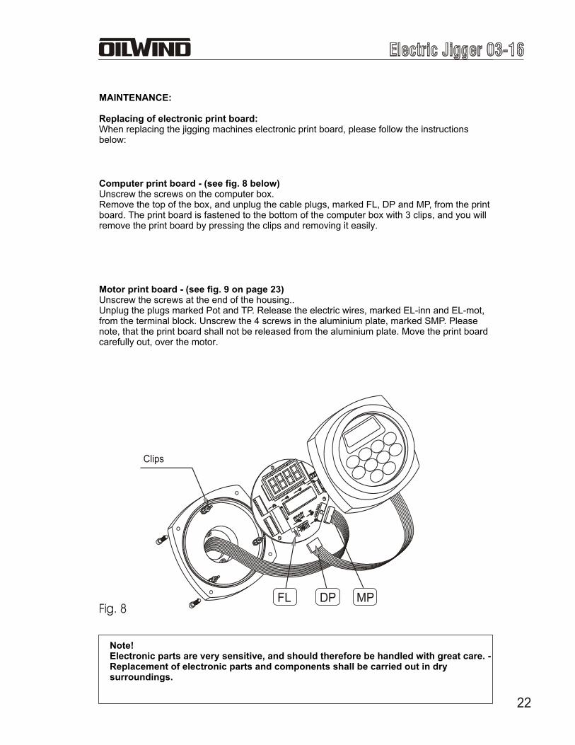
Note!Electronic parts are very sensitive, and should therefore be handled with great care. - Replacement of electronic parts and components shall be carried out in dry surroundings.
Computer print board - (see fig. 8 below)Unscrew the screws on the computer box. Remove the top of the box, and unplug the cable plugs, marked FL, DP and MP, from the print board. The print board is fastened to the bottom of the computer box with 3 clips, and you will remove the print board by pressing the clips and removing it easily.
Fig. 8
Clips
DPFL MP

23
Humidity bag (please see drawing on the next page)
To protect the electric and electronic parts and components in the machine against humidity which can appear during temperature changes, there is a humidity bag (Silica Gel) inside the machine (attached to the electric motor).Our recommendation is, that this bag will be replaced when you are servicing the machine, or at least every year.
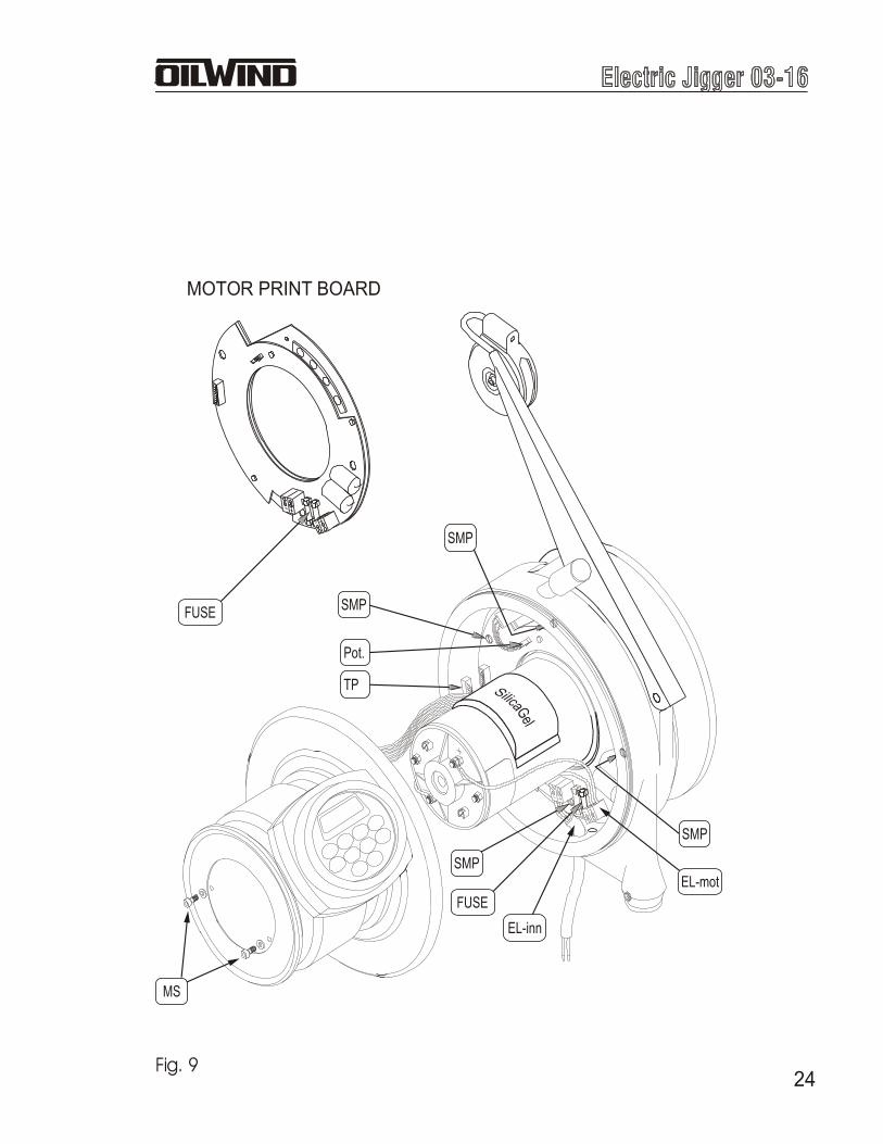
24Fig. 9
EL-inn
EL-mot
TP
Pot.
SMP
SMP
SMP
SMP
FUSE
MS
MOTOR PRINT BOARD
FUSE

25
STANDARD PROGRAM:
Pays out the lineto the bottom
Reels up 1 fathom and begins jiggingStarts jiggingPays out the line to the bottomReels up 1 fathom.....and continues.....
Instructions:
Press the (DOWN) button. The machine pays out the line to the bottom - and starts fishing as
described above. This fishing method is the machine's standard program.
If you have adjusted some values, but wish to return to the standard program, then use the
(CLEAR) button. By pressing the button for 5 seconds, or until the whistle gives one long sound, the computer will return to the standard program.
Fig. 10
JIG NUMBERHE
IGH
T F
RO
M B
TM
.JI
G T
RA
VE
L

26
THE SEARCH MODE:
Pays outline to
bottom.
Fig. 11
Adjustment instructions:
Press the (SEARCH) button (the light starts flashing) and then the
(DOWN) button. The displays shows a (colon), and the light in the
(SEARCH) button is on. The machine is now adjusted to search from the bottom and
upwards the water. The machine is jigging, moves up the water and starts jigging again and so on, until it reaches the value, adjusted as the Search Range. The machine will then again pay the line to the bottom, and starts searching again (see further information in JIG FUNCTIONS, 7: SEARCH RANGE). In the standard program the Search Range is pre-set to 40, or the machine will search up to 40 fathoms. The mode can be adjusted as to your requirements.
To start fishing from the bottom again, press the (SEARCH) button, and then the
(DOWN) button.
At the end of each JIG NUMBERthe line will move up the watercolumn a distance of one JIG TRAVELand continue untilfish are found

27
THE ADJUST DEPTH MODE:
Line drops to specified depthand begins to jig
Fig. 12
Adjustment instructions:
Press the (ADJUST DEPTH) button (the light starts flashing), then adjust the planned depth by
using the (PLUS) or (MINUS buttons, press the (DOWN) button, and the machine
starts fishing at the adjusted depth (the button's light is on during fishing at the adjusted depth).
To start fishing from the bottom again, press the buttons as follows:
(ADJUST DEPTH), (CLEAR) and (DOWN).

28
Adjustment instructions:
Press the (ADJUST JIG) button (the light is on). Press as many times as necessary to get
the display to show . Adjust the value with the (PLUS) or (MINUS) button (the
light starts flashing).The adjustment indicates in seconds the pause between jigging period.
To confirm the adjusted value, press the (ADJUST JIG) button (the light stops flashing).
To activate the new program press the (DOWN) button.
If you wish to se how many fathoms of line are paid out, press the
(WEIGHT - DEPTH) button (the light in the (ADJUST JIG) button is switched off).
Pays outthe line tobottom
Reels up 1 fathomMakes one jigMakes a pause in accordancewith the adjustment (JIG PAUSE)Makes one jigFinds bottomand continoues....
THE JIG PAUSE MODE:
Fig. 13
JIG PAUSE
29
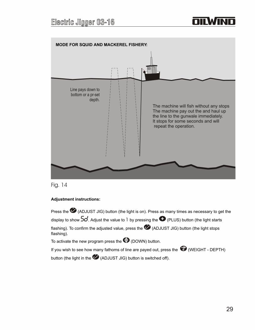
MODE FOR SQUID AND MACKEREL FISHERY:
The machine will fish without any stopsThe machine pay out the and haul upthe line to the gunwale immediately.It stops for some seconds and will repeat the operation.
Line pays down tobottom or a pr-set
depth.
Fig. 14
Adjustment instructions:
Press the (ADJUST JIG) button (the light is on). Press as many times as necessary to get the
display to show . Adjust the value to 1 by pressing the (PLUS) button (the light starts
flashing). To confirm the adjusted value, press the (ADJUST JIG) button (the light stops
flashing).
To activate the new program press the (DOWN) button.
If you wish to see how many fathoms of line are payed out, press the (WEIGHT - DEPTH)
button (the light in the (ADJUST JIG) button is switched off).

30
THIS BLANKPAGE IS INTENTIONALLY LEFT

31THIS PAGE IS INTENTIONALLY LEFT BLANK

32
THIS PAGE IS INTENTIONALLY LEFT BLANK
33
Examples of mounting brackets:
Clip Bracket
Adjustable Bracket
34
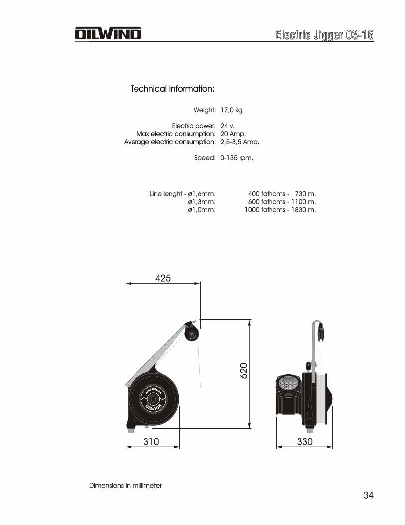
310
425
62
0
330
Weight:
Speed:
Electric power:Max electric consumption:
Average electric consumption:
Line lenght - ø1,6mm:ø1,3mm:ø1,0mm:
17,0 kg
24 v.20 Amp.2,5-3,5 Amp.
0-135 rpm.
400 fathoms - 730 m.600 fathoms - 1100 m.
1000 fathoms - 1830 m.
Technical Information:
Dimensions in millimeter

LOCAL REPRESENTATIVE:
PRODUCED BY:
P.O. BOX 9FO-370 MIÐVÁGURFØROYRAR(Faroe Islands)
Tlf: +298 33 24 22Fax: +298 333 222http: \\www.oilwind.foE-mail: [email protected]