fully automatic gasification combustion boiler for solid fuels · output 500 - 10 000 kw...
TRANSCRIPT
Output 500 - 10 000 kW
Temperature 110 - 180 °С
Pressure 4, 6, 10 or 16 bar
Fully automatic gasification combustion boiler for
solid fuels For district heating plants, the wood processing industry, greenhouses, etc.
Laatukattila Oy has manufactured heating boilers for solid fuels since 1953. Our environmentallyfriendly biomass boiler LAKA Y is the result of continuous product development. It is based on a two-stage gasification combustion technology that can efficiently burn even poor quality fuels with highmoisture content. The Laka Y gasification combustion boiler offers more than 90 % efficiency, an outputrange 10…130 %, and flue gas dust emissions are very low, normally 10…50 mg/nm³.
Thanks to the clean combustion technology, the LAKA Y boiler needs cleaning only once a year.
HIGH UTILISATION RATEAvailability is usually 100 %. Output range 10…130 %.
EFFICIENCY 90…94 % depending on equipment and fuels.
COMBUSTION METHODTwo-stage gasification combustion in two successive combustion chambers.
FUELSWoodchips made of forest residues, woodchips made of whole trees and tree stumps, bark, briquettes, sawdust, shavings, sod peat, waste wood chips and agricultural biomass fuels. Moisture content is between 5 and 65 %. Fuel particle size 0-400 mm. An optional oil burner can be installed for reserve use.
MOVING INCLINED GRATEThe hydraulic grate always moves in tandem with the boiler load.
VERY LOW FLUE GAS EMISSIONSDust content usually < 50 mg/nm³.NOₓ< 100-500 mg/nm³, depending on the fuel.CO < 100 ppm.
LOW OPERATING AND MAINTENANCE COSTS Low maintenance costs: typically, the boiler needs cleaning once a year. The boiler’s own energy usage is approx. 0.5 % (about 5 kWh electricity for each 1000 kWh of generated heat).
SAFE AND DURABLELong and successful history.The gasification chamber is made of acid resistant steel.
LAATUKATTILA OYVihiojantie 10, 33800 TAMPERE, Finland
Phone +358 3 214 1411 [email protected]
Fax +358 3 212 1528 www.laka.fi
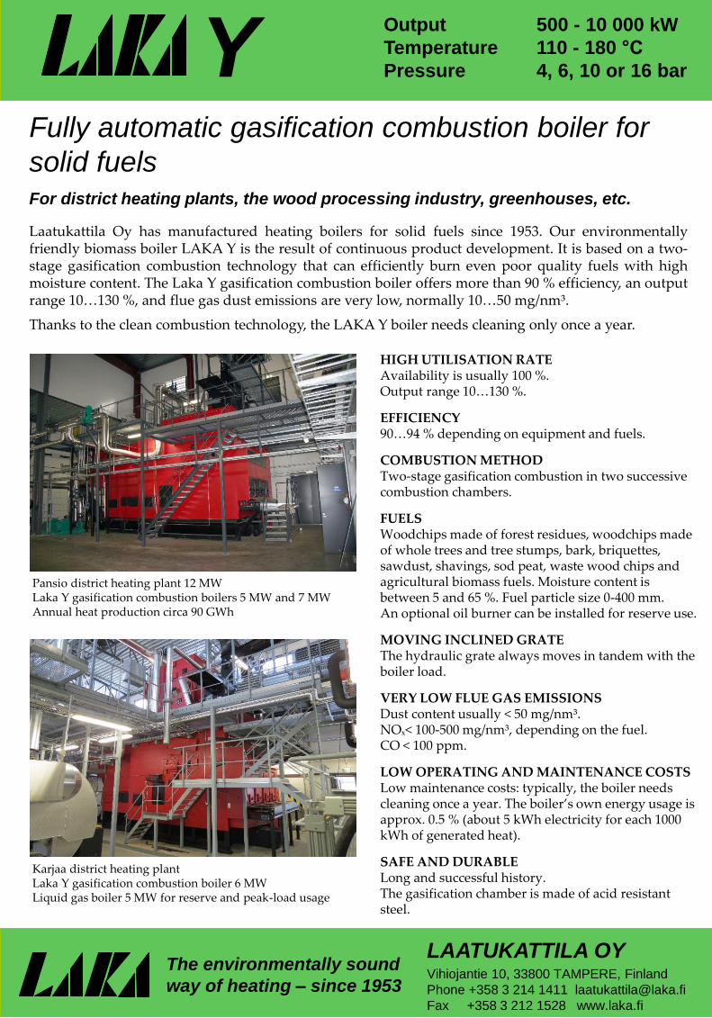
Pansio district heating plant 12 MWLaka Y gasification combustion boilers 5 MW and 7 MWAnnual heat production circa 90 GWh
Karjaa district heating plantLaka Y gasification combustion boiler 6 MWLiquid gas boiler 5 MW for reserve and peak-load usage
The environmentally sound
way of heating – since 1953
Y

The LAKA Y gasification boiler is based on our many patented innovations which allow us to exploit the advantages of a gasification combustion boiler at the price of a conventional grate combustion boiler.
Our patented two-stage gasification combustion (pat. 8570) is low in nitrogen emissions. In contrast to conventional grate combustion, the LAKA Y’s glowing ember bed is stationary regardless of power output. And the glowing ember bed is so thick (about 80 cm) that all combustion air oxygen is consumed within the ember bed.
In the absence of oxygen more than 90 % of the nitrogen becomes nitrogen molecules (N₂). The remaining nitrogen forms the mainly low oxygenated nitrogen compounds N₂O and NO. This is ecologically important, because acid rain causing toxic NO₂ compound emissions are very low.
The VTT Technical Research Centre of Finland tested our two-stage gasification combustion boiler (Laka Y 540 kW) and found that when chipboard was burnt nitrogen oxide emissions were at the same level as when clean woodchips were burnt in a grate combustion boiler, in spite of the fact that the nitrogen content of chipboard was more than thirty times higher.
Gasification combustion has two stages.
At the first stage primary air (5) enters through the grate to the bottom of the thick glowing ember bed and combustion continues within the ember bed as long as there is enough free oxygen and until all the oxygen has become carbon dioxide (O₂+C=CO₂) The carbon dioxide then reacts with glowing carbon and forms carbon monoxide (CO₂+C=2CO).
As the gas rises from the glowing ember bed, it is mixed with secondary air (11), causing the gas to ignite. The burning gas enters a narrow chamber where tertiary air (12) is blown into the mixture from all sides, and the gas burns completely within a hot combustion chamber lined with firebricks.
The hot gas rises further into an afterburning chamber that prolongs combustion and reduces the amount of unburned gases and dust especially when the fuel used is of low quality and high moisture content.
Because the first stage of combustion takes place within the thick ember bed, which acts like an active carbon filter removing almost all fly ash from the gas, only 2 % of the ash formed rises with the flue gas flow. The remaining 98 % stays in the ember bed and exits from below to the ash conveyor. This means that the flue gas dust content within the boiler is only circa 50 mg/nm³, keeping the boiler clean and the boiler needs to be cleaned only once a year as part of its annual maintenance.
P Fuel1. Upper gates for fuel feeding2. Fuel feed silo3. Lower gates for fuel feeding4. Internal fuel silo 5. Primary air for gasification6. Water level of ash conveyor
7. Ash removal from the grate8. Blades of ash scraper conveyor9. Slag removal at the back of the grate10. Ash removal of the convection part11. Secondary air12. Tertiary air13. Observation ports of combustion
14. Biogas combustion chamber15. Combustion air preheater16. Flue gas cleaner17. Flue gas fan18. Clean flue gas19. Ash removal to ash container
LAKA Y GASIFICATION COMBUSTION BOILER
The flue gas dust content of a conventional grate combustion boiler is more than 1000 mg/nm³. This is why such boilers are equipped with compressed air soot cleaning systems, the disadvantage of which is dust discharges that exceed emission requirements and leave an environmental footprint.
In grate combustion boilers the thickness of the glowing ember bed is initially around 30 cm. The grate moves the ember bed so that the whole bed is burned after travelling along the whole length of the grate. The grate’s movement should always be adjusted to the power output of the boiler and the type of fuel used.
In Laka Y boilers combustion is not regulated by moving grates. The thick ember bed remains still and the grate moves simply to cut ash from under the ember bed. The regulation of combustion in Laka Y boilers is simpler because only the combustion air needs adjusting. The regulation happens automatically even if the quality, size or moisture content of the fuel changes. Gasification combustion adjusts to the changes in boiler load much faster than grate combustion.
On top of the thick glowing ember bed there are still more than 2 metres of fuel in the internal silo. In case of a power cut or other disruption, the Laka Y boiler runs standby and can restart automatically within another 3 days if the problem is fixed.
In a grate combustion boiler even short-term disruptions may cause the thin ember bed to burn down completely and the boiler requires many hours work to start and reach its required output.
Big fuel storage with a programmed crab crane
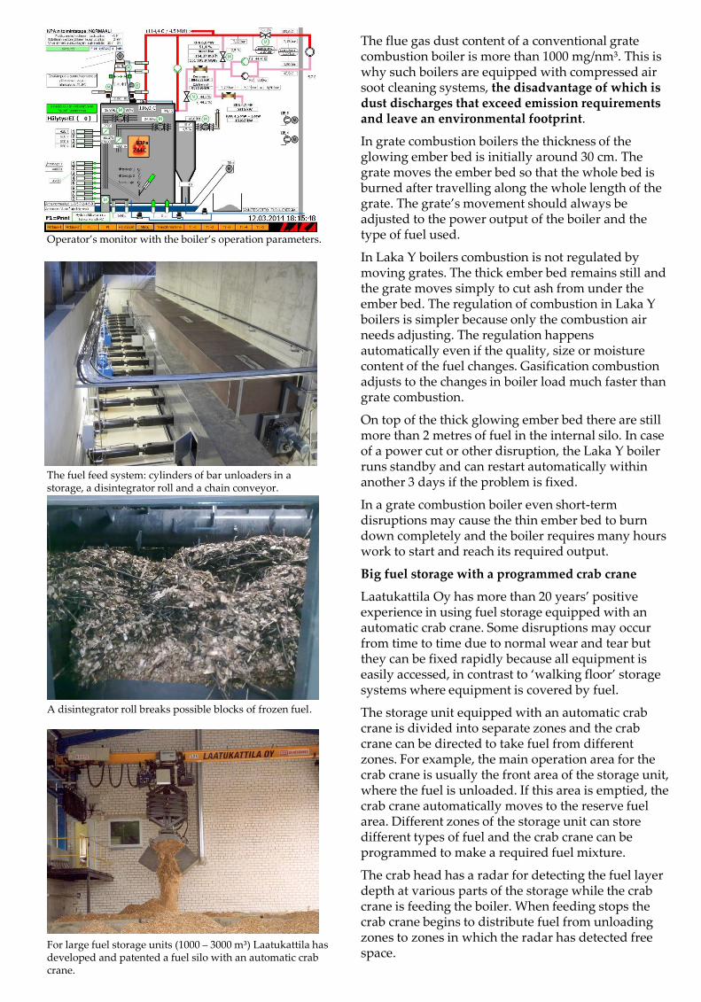
Laatukattila Oy has more than 20 years’ positive experience in using fuel storage equipped with an automatic crab crane. Some disruptions may occur from time to time due to normal wear and tear but they can be fixed rapidly because all equipment is easily accessed, in contrast to ‘walking floor’ storage systems where equipment is covered by fuel.
The storage unit equipped with an automatic crab crane is divided into separate zones and the crab crane can be directed to take fuel from different zones. For example, the main operation area for the crab crane is usually the front area of the storage unit, where the fuel is unloaded. If this area is emptied, the crab crane automatically moves to the reserve fuel area. Different zones of the storage unit can store different types of fuel and the crab crane can be programmed to make a required fuel mixture.
The crab head has a radar for detecting the fuel layer depth at various parts of the storage while the crab crane is feeding the boiler. When feeding stops the crab crane begins to distribute fuel from unloading zones to zones in which the radar has detected free space.
For large fuel storage units (1000 – 3000 m³) Laatukattila has developed and patented a fuel silo with an automatic crab crane.
A disintegrator roll breaks possible blocks of frozen fuel.
The fuel feed system: cylinders of bar unloaders in a storage, a disintegrator roll and a chain conveyor.
Operator’s monitor with the boiler’s operation parameters.
Oulu
Tampere
TurkuHelsinki
Espoo
Vantaa
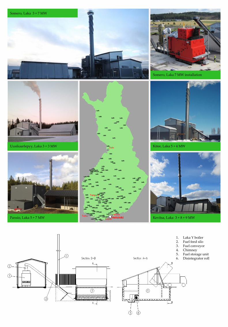
Kevitsa, Laka 3 + 8 + 9 MW
Карья, Laka Y, 5 + 6 МВт
Pansio, Laka 5 + 7 MW
Uusikaarlepyy, Laka 3 + 3 MW
Somero, Laka 3 + 7 MW
Kitee, Laka 5 + 4 MW
Somero, Laka 7 MW installation
1. Laka Y boiler2. Fuel feed silo3. Fuel conveyor4. Chimney5. Fuel storage unit6. Disintegrator roll