fundamental gc-ms gc-ms interfaces -...
TRANSCRIPT

i Wherever you see this symbol, it is important to access the on-line course as there is interactive material that cannot be fully shown in this reference manual.
Mass Spectrometry
Fundamental GC-MS
GC-MS Interfaces
Aims and Objectives
Aims and Objectives
Aims
Explain the working principle of the most important GC/MS interfaces currently available
Explore the correct interface types for use with different GC Columns and MS Instrument types
Describe some of the more common problems affecting the interface in GC/MS equipment
Explain the principles of Curtain Gas equipment to allow column changing without venting the analyser
Objectives At the end of this Section you should be able to:
Describe the most common interfaces for GC-MS drawing clear distinctions between them and explaining the working principles associated to each of them
List the main elements present in a GC/MS interface
Choose the correct interface for a given instrument configuration
Undertake troubleshooting of MS interface problems
© Crawford Scientific www.chromacademy.com
2
Content Introduction 3 Column Diameter 3
The Jet Separator 4 The Bieman Concentrator 5 Direct Introduction 5 Vacuum System Considerations 6
Coupling GC to MS Detectors –Jet Separator 6 Coupling GC to MS Detectors –Direct Interface 7 Interface-Column Coupling I 8 Interface-Column Coupling II 9 Interface-Column Coupling III 10 Interface-Column Coupling IV 11 References 12
© Crawford Scientific www.chromacademy.com
3
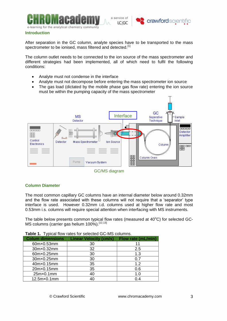
Introduction After separation in the GC column, analyte species have to be transported to the mass spectrometer to be ionised, mass filtered and detected.[1] The column outlet needs to be connected to the ion source of the mass spectrometer and different strategies had been implemented, all of which need to fulfil the following conditions:
Analyte must not condense in the interface
Analyte must not decompose before entering the mass spectrometer ion source
The gas load (dictated by the mobile phase gas flow rate) entering the ion source must be within the pumping capacity of the mass spectrometer
GC/MS diagram
Column Diameter The most common capillary GC columns have an internal diameter below around 0.32mm and the flow rate associated with these columns will not require that a ‘separator’ type interface is used. However 0.32mm i.d. columns used at higher flow rate and most 0.53mm i.s. columns will require special attention when interfacing with MS instruments. The table below presents common typical flow rates (measured at 40oC) for selected GC-MS columns (carrier gas helium 100%).[12,13] Table 1. Typical flow rates for selected GC-MS columns.
Colum dimensions Linear Velocity (cm/s) Flow rate (mL/min)
60m×0.53mm 30 11
30m×0.32mm 32 2.5
60m×0.25mm 30 1.3
30m×0.25mm 30 0.7
40m×0.15mm 35 1.2
20m×0.15mm 35 0.6
25m×0.1mm 40 1.0
12.5m×0.1mm 40 0.4
Interface
© Crawford Scientific www.chromacademy.com
4
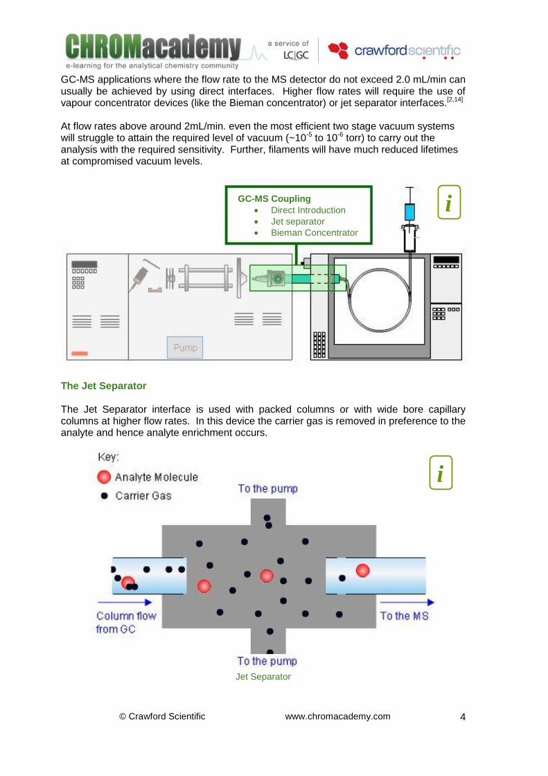
GC-MS applications where the flow rate to the MS detector do not exceed 2.0 mL/min can usually be achieved by using direct interfaces. Higher flow rates will require the use of vapour concentrator devices (like the Bieman concentrator) or jet separator interfaces.[2,14] At flow rates above around 2mL/min. even the most efficient two stage vacuum systems will struggle to attain the required level of vacuum (~10-5 to 10-6 torr) to carry out the analysis with the required sensitivity. Further, filaments will have much reduced lifetimes at compromised vacuum levels.
The Jet Separator The Jet Separator interface is used with packed columns or with wide bore capillary columns at higher flow rates. In this device the carrier gas is removed in preference to the analyte and hence analyte enrichment occurs.
Jet Separator
i GC-MS Coupling
Direct Introduction
Jet separator
Bieman Concentrator
i
© Crawford Scientific www.chromacademy.com
5
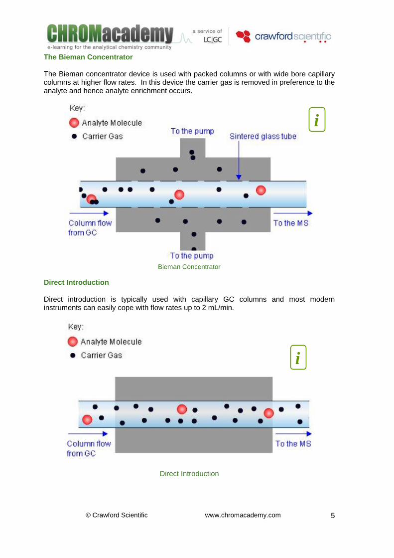
The Bieman Concentrator The Bieman concentrator device is used with packed columns or with wide bore capillary columns at higher flow rates. In this device the carrier gas is removed in preference to the analyte and hence analyte enrichment occurs.
Bieman Concentrator
Direct Introduction Direct introduction is typically used with capillary GC columns and most modern instruments can easily cope with flow rates up to 2 mL/min.
Direct Introduction
i
i
© Crawford Scientific www.chromacademy.com
6
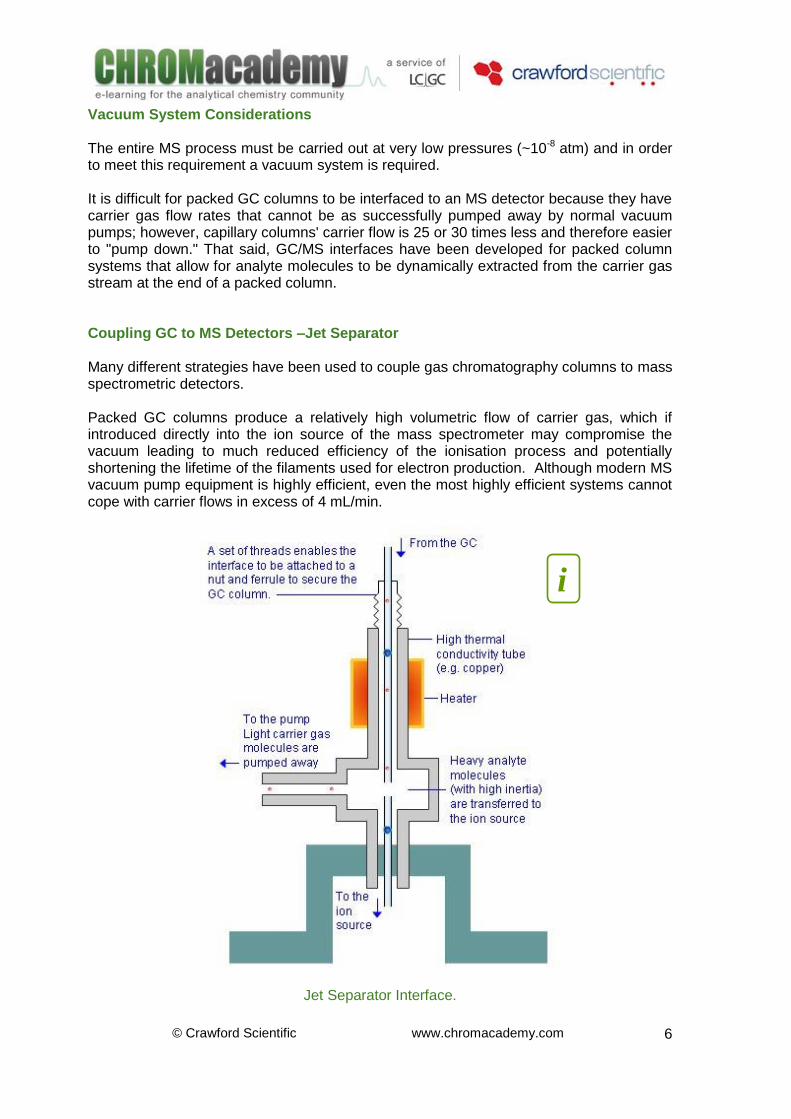
Vacuum System Considerations The entire MS process must be carried out at very low pressures (~10-8 atm) and in order to meet this requirement a vacuum system is required. It is difficult for packed GC columns to be interfaced to an MS detector because they have carrier gas flow rates that cannot be as successfully pumped away by normal vacuum pumps; however, capillary columns' carrier flow is 25 or 30 times less and therefore easier to "pump down." That said, GC/MS interfaces have been developed for packed column systems that allow for analyte molecules to be dynamically extracted from the carrier gas stream at the end of a packed column. Coupling GC to MS Detectors –Jet Separator Many different strategies have been used to couple gas chromatography columns to mass spectrometric detectors. Packed GC columns produce a relatively high volumetric flow of carrier gas, which if introduced directly into the ion source of the mass spectrometer may compromise the vacuum leading to much reduced efficiency of the ionisation process and potentially shortening the lifetime of the filaments used for electron production. Although modern MS vacuum pump equipment is highly efficient, even the most highly efficient systems cannot cope with carrier flows in excess of 4 mL/min.
Jet Separator Interface.
i
© Crawford Scientific www.chromacademy.com
7
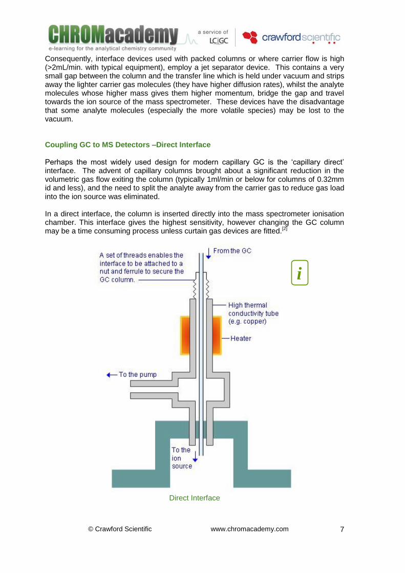
Consequently, interface devices used with packed columns or where carrier flow is high (>2mL/min. with typical equipment), employ a jet separator device. This contains a very small gap between the column and the transfer line which is held under vacuum and strips away the lighter carrier gas molecules (they have higher diffusion rates), whilst the analyte molecules whose higher mass gives them higher momentum, bridge the gap and travel towards the ion source of the mass spectrometer. These devices have the disadvantage that some analyte molecules (especially the more volatile species) may be lost to the vacuum. Coupling GC to MS Detectors –Direct Interface Perhaps the most widely used design for modern capillary GC is the ‘capillary direct’ interface. The advent of capillary columns brought about a significant reduction in the volumetric gas flow exiting the column (typically 1ml/min or below for columns of 0.32mm id and less), and the need to split the analyte away from the carrier gas to reduce gas load into the ion source was eliminated. In a direct interface, the column is inserted directly into the mass spectrometer ionisation chamber. This interface gives the highest sensitivity, however changing the GC column may be a time consuming process unless curtain gas devices are fitted.[2]
Direct Interface
i
© Crawford Scientific www.chromacademy.com
8
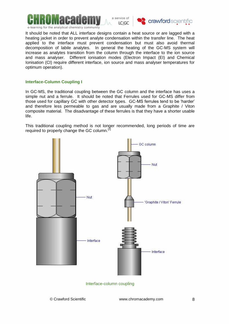
It should be noted that ALL interface designs contain a heat source or are lagged with a heating jacket in order to prevent analyte condensation within the transfer line. The heat applied to the interface must prevent condensation but must also avoid thermal decomposition of labile analytes. In general the heating of the GC-MS system will increase as analytes transition from the column through the interface to the ion source and mass analyser. Different ionisation modes (Electron Impact (EI) and Chemical Ionisation (CI) require different interface, ion source and mass analyser temperatures for optimum operation). Interface-Column Coupling I In GC-MS, the traditional coupling between the GC column and the interface has uses a simple nut and a ferrule. It should be noted that Ferrules used for GC-MS differ from those used for capillary GC with other detector types. GC-MS ferrules tend to be ‘harder’ and therefore less permeable to gas and are usually made from a Graphite / Viton composite material. The disadvantage of these ferrules is that they have a shorter usable life. This traditional coupling method is not longer recommended, long periods of time are required to properly change the GC column.[2]
Interface-column coupling
© Crawford Scientific www.chromacademy.com
9
The process of changing column is started with turning the mass spectrometer and the vacuum system off. The GC column can be replace as soon as the interface reaches a temperature low enough to safety dismantle it, then and only then the mass spectrometer can be turned on.[3] One of the main reasons for the long time required to change the GC-MS column is the need for re-establishing optimum levels of vacuum (moisture and air) after the mass spectrometer was down. The removal of water is always the biggest problem, taking up to twelve hours in most systems. Interface-Column Coupling II Changing GC columns when using a direct interface can be protracted, as to prevent catastrophic vacuum loss (and possible damage to the vacuum system), the instrument must be vented (i.e. the vacuum system must be gradually slowed until the instrument is no longer under vacuum). This can be time consuming and to vent and then pump down an instrument (i.e. re-establish vacuum) may take between 4 and 8 hours. Various devices exist to allow the GC-MS column to be changed without having to vent the mass spectrometer.
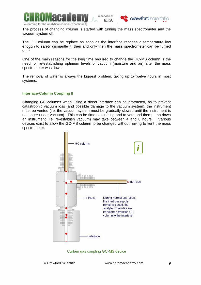
Curtain gas coupling GC-MS device
i
© Crawford Scientific www.chromacademy.com
10
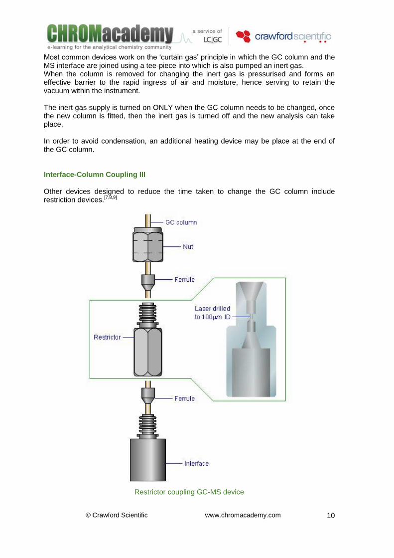
Most common devices work on the ‘curtain gas’ principle in which the GC column and the MS interface are joined using a tee-piece into which is also pumped an inert gas. When the column is removed for changing the inert gas is pressurised and forms an effective barrier to the rapid ingress of air and moisture, hence serving to retain the vacuum within the instrument. The inert gas supply is turned on ONLY when the GC column needs to be changed, once the new column is fitted, then the inert gas is turned off and the new analysis can take place. In order to avoid condensation, an additional heating device may be place at the end of the GC column. Interface-Column Coupling III Other devices designed to reduce the time taken to change the GC column include restriction devices.[7,8,9]
Restrictor coupling GC-MS device
© Crawford Scientific www.chromacademy.com
11
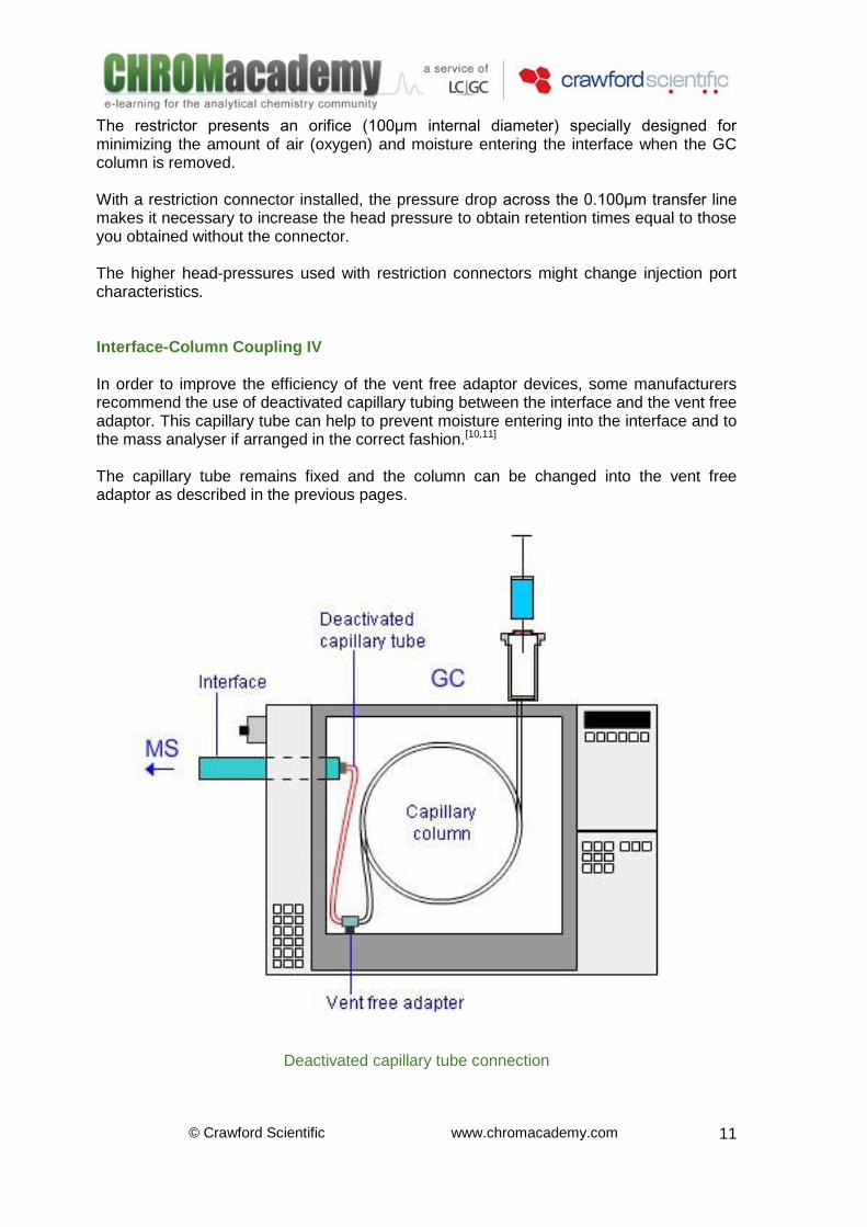
The restrictor presents an orifice (100μm internal diameter) specially designed for minimizing the amount of air (oxygen) and moisture entering the interface when the GC column is removed. With a restriction connector installed, the pressure drop across the 0.100μm transfer line makes it necessary to increase the head pressure to obtain retention times equal to those you obtained without the connector. The higher head-pressures used with restriction connectors might change injection port characteristics. Interface-Column Coupling IV In order to improve the efficiency of the vent free adaptor devices, some manufacturers recommend the use of deactivated capillary tubing between the interface and the vent free adaptor. This capillary tube can help to prevent moisture entering into the interface and to the mass analyser if arranged in the correct fashion.[10,11] The capillary tube remains fixed and the column can be changed into the vent free adaptor as described in the previous pages.
Deactivated capillary tube connection
© Crawford Scientific www.chromacademy.com
12
References 1. A. Braithwaite and F. J. Smith. “Chromatographic Methods” Blackie Academic & and Professional. PP 375-379. UK 1996 2. Suart C. Hansen and Jean-Luc Truche. “Flow-limited direct GC/MS interface” United States Patent # 4662914, May 5, 1987. 3. Robert Stevenson. “New instruments for separation science at PITTCON® 2000: The new age of alliances?” American Laboratory –Separation science. Pp 19-42. May 2000 4. SGE Chromatography Products. http://www.sge.com/ 5. MS No-Vent. Installation & Operating Instructions. Application note SGE. 6. Alltech GC/MS Switching Valve. Application note. Copyright 2004 Alltech Associates, Inc. 7. http://www.restek.com 8. EZ No-Vent™ GC/MS Connector for Agilent 5971/5972 and 5973 Mass Spectrometers. Application note RESTEK, July 2007. 9. CLINICAL/ FORENSICS –Products & Applications for GC & HPLC. Application note RESTEK, 2006. 10. http://www.frontier-lab.com/products/vf-adaptor/index.html 11. Vent-free GC/MS Adapter. Frontier Laboratories Ltd. Application note. 12. GC Columns. www.varianinc.co 13. “The Essential Chromatography Catalog” Agilent Technologies. 14. Raymond P. W. Scott, “Tandem Techniques” John Wiley & Sons. Pp 165-173. USA 1997
