“fundamentals of ip networking 2017 webinar series” · “fundamentals of ip networking 2017...
TRANSCRIPT

“Fundamentals of IP Networking 2017 Webinar Series”
Part 3 IP Routing and Internetworking Fundamentals
Wayne M. Pecena, CPBE, CBNE Texas A&M University
Educational Broadcast Services – KAMU Public Broadcasting
June_2017 IP_Net_Fundamentals-Part-3

“Fundamentals of IP Networking 2017 Webinar Series” Advertised Presentation Scope
Part 1- Introduction to IP Networking Standards & the Physical Layer Part 2 - Ethernet Switching Fundamentals and Implementation Part 3 - IP Routing and Internetworking Fundamentals Continuing The Fundamentals of IP Networking Series, Part 3 of the webinar series focuses upon understanding IP routing and applying concepts in practical inter-networking by exploring the foundation and protocols of Layer 3 of the OSI model. Specific topics to be covered include understanding the role of routed protocols, IP addressing (subnetting), IP routing protocol section, and the role of layer 3 protocols such as ICMP and ARP. Part 4 - Building a Segmented IP Network Focused On Performance & Security - July 25 Part 5 - Cybersecurity Fundamentals & Securing the Network - August 29
2
Today’s Outline:
• Takeaway Review From Part 2
• The Network Layer
• Layer 3 Protocols – Overview
– ICMP Focus
• Routing and the Routing Protocol – Overview
– Selection
• The IP Address – IPv4 Focus
– IPv6 Introduction
• Takeaways, References, Questions, and Maybe Some Answers
3

Part 2 - Takeaway Point Review • The Ethernet Switch is the Fundamental LAN Building Block
• VLANs Allow a Common Physical Infrastructure to Support Multiple Isolated Networks or Subnets
• Each Network, Subnet, or VLAN is a Broadcast Domain With a Unique IP Address Scheme
• Ethernet Switches Eliminate (minimize) Collision Domains
• IP Routing Must Be Used for Communications Between VLANs
• Network Traffic May Be Isolated Because of:
– Policy
– Regulations
– Security
– Performance
• An Ethernet Frame is “Tagged” to Denote VLAN Membership on a “Trunk” or “Tagged” Interface
4

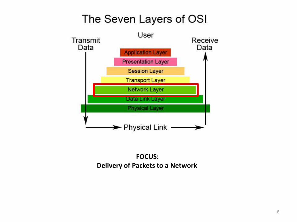
THE NETWORK LAYER
5
6
FOCUS: Delivery of Packets to a Network

Types of IP Packets on an IPv4 Network
• Unicast
– One Send Host TO One Receive Host
• Broadcast
– One Send Host TO ALL Hosts Within the Broadcast Domain (Network Subnet)
• Multicast
– One Send Host TO Specific Hosts
7
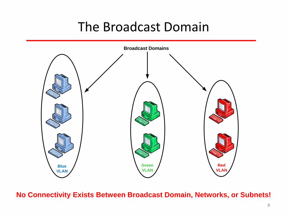
The Broadcast Domain
Red
VLAN
Green
VLANBlue
VLAN
Broadcast Domains
No Connectivity Exists Between Broadcast Domain, Networks, or Subnets!
8

Add Connectivity Between Broadcast Domains
Red
VLAN
Green
VLANBlue
VLAN
Network #1 Network #3
Network #2
GE0
FE0
GE1
GE2
Add Router
9

10
Application
Session
Presentation
Transport
Physical
Data Link
Network
Application
Session
Presentation
Transport
Physical
Data Link
Network
Physical
Data Link
Physical
Data Link
Physical
Data Link
Physical
Data Link
Physical
Data Link
Physical
Data Link
Network Network
Layer 2
Device
Layer 2
Device Layer 3
Device
LAYER 3 PROTOCOLS
11

IPv4 Packet – Layer 3 RFC 791
12
Version
(4)
Header
(4)
Precedence / Type
(8)
Length
(16)
Identification
(16)
Flag
(3)
Offset
(13)
Time to Live
(8)
Protocol
(8)
Header Checksum
(16)
Source IP Address
(32)
Options & Padding
(0 or 32)
Destination IP Address
(32)
Packet Payload
(Transport Layer Data)
32 bits
20
Bytes

IP Protocols (snapshot)
13
https://www.iana.org/assignments/protocol-numbers/protocol-numbers.xhtml
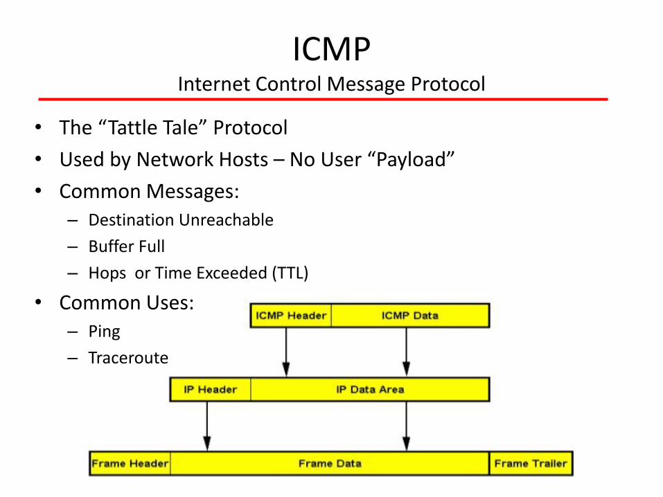
ICMP Internet Control Message Protocol
• The “Tattle Tale” Protocol
• Used by Network Hosts – No User “Payload”
• Common Messages: – Destination Unreachable
– Buffer Full
– Hops or Time Exceeded (TTL)
• Common Uses: – Ping
– Traceroute

ICMP Messages: • Platform Utilized
by Ping & Traceroute
Utilities
15
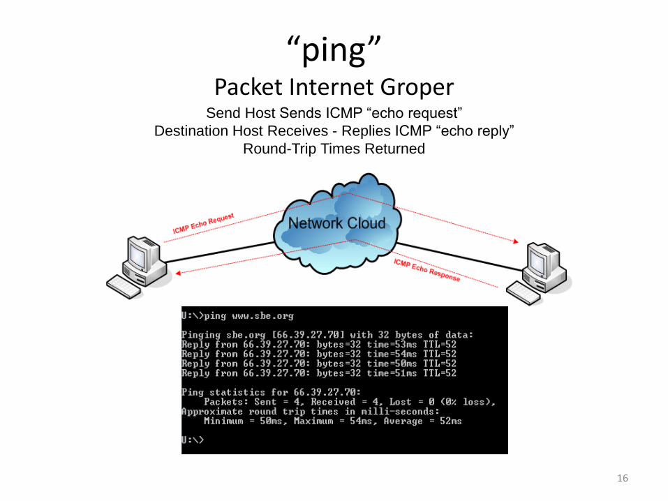
“ping” Packet Internet Groper
16
Send Host Sends ICMP “echo request”
Destination Host Receives - Replies ICMP “echo reply”
Round-Trip Times Returned
ROUTING AND THE ROUTING PROTOCOL
17
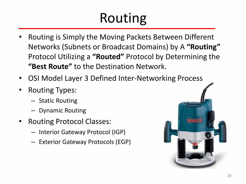
Routing • Routing is Simply the Moving Packets Between Different
Networks (Subnets or Broadcast Domains) by A “Routing” Protocol Utilizing a “Routed” Protocol by Determining the “Best Route” to the Destination Network.
• OSI Model Layer 3 Defined Inter-Networking Process
• Routing Types: – Static Routing
– Dynamic Routing
• Routing Protocol Classes: – Interior Gateway Protocol (IGP)
– Exterior Gateway Protocols (EGP)
18

Routing • Simply Sending Packets from One Network to A Destination
Network via the Best Route
• Protocol Based Operation: – Routed Protocol – Packet Structure Supporting Logical Addressing
(IPv4/6)
– Routing Protocol – Learns Routes & Routing Info Exchange (RIP, OSPF, EIGRP)
• Best Route Determined by: – IP Address Prefix Length
– Metric
– Administrative Distance
19

The Router • Router Functions:
– Learn Available Networks
– Maintain Accurate Routing Information Based (RIB) or “Routing Table”
– Translate Layer 2 Headers (where different network types)
– Prevent Loops (where redundant paths)
– Determine “Best” Packet Forwarding Path (destination network)
• Destination-Based Routing: – Packet Header Decoded – Get Destination Address
– Destination Address Lookup in Routing Table (RIB)
– Determine Egress Interface to Forward Packet To
– Re-Encapsulates Layer 2 Header Information
20
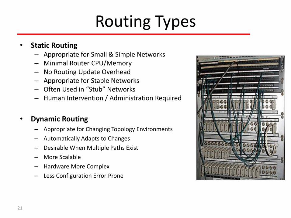
Routing Types • Static Routing
– Appropriate for Small & Simple Networks – Minimal Router CPU/Memory – No Routing Update Overhead – Appropriate for Stable Networks – Often Used in “Stub” Networks – Human Intervention / Administration Required Yy
• Dynamic Routing – Appropriate for Changing Topology Environments
– Automatically Adapts to Changes
– Desirable When Multiple Paths Exist
– More Scalable
– Hardware More Complex
– Less Configuration Error Prone
21

Dynamic Routing Categories
• Distance Vector Routing Protocol
– Periodic Routing Table Updates
– Each Router Receives Updates Neighbors (Trust)
– “Distance” Used as a Metric
• Link State Routing Protocol
– Routing Table Updates As Changes Occur
– Each Router Receives Updates From All Others
– Maintains Neighbor, Topology, & Shortest-Path Tables
– “Cost” Used as a Metric
22

Routing Metrics & Administrative Distance Determines The Best Path to Target Host
• Cost Metrics:
– Hop Count The Number of Routers in a Path
– Bandwidth Throughput (bps)
– Load Traffic Flowing Through a Router
– Delay Network Latency (distance or congestion)
– Reliability Amount of Downtime of a Network Path
• Administrative Distance
– Indicates Believability of the Route
– Utilized When Multiple Protocols Are Used
– Cab Be Used to Prefer A Certain Path When Multiple Paths Exist
– Each Routing Protocol Has a Default Administrative Distances
Smaller Metrics = Best Route
Lower Administrative Distance = More Believed
23
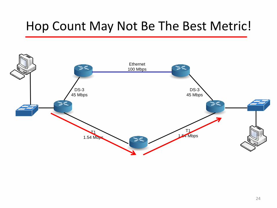
Hop Count May Not Be The Best Metric!
Ethernet
100 Mbps
DS-3
45 Mbps
T1
1.54 Mbps
DS-3
45 Mbps
T1
1.54 Mbps
24
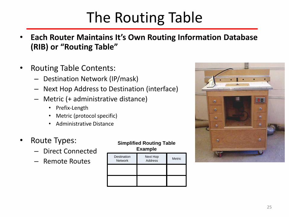
The Routing Table • Each Router Maintains It’s Own Routing Information Database
(RIB) or “Routing Table”
• Routing Table Contents: – Destination Network (IP/mask)
– Next Hop Address to Destination (interface)
– Metric (+ administrative distance) • Prefix-Length
• Metric (protocol specific)
• Administrative Distance
• Route Types: – Direct Connected
– Remote Routes Destination
Network
Next Hop
AddressMetric
Simplified Routing Table
Example
25
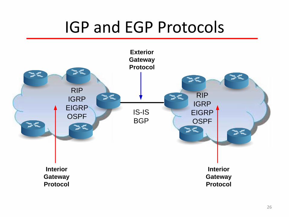
IGP and EGP Protocols Exterior
Gateway
Protocol
Interior
Gateway
Protocol
Interior
Gateway
Protocol
IS-IS
BGP
RIP
IGRP
EIGRP
OSPF
RIP
IGRP
EIGRP
OSPF
26

Routing Protocol Choices IMHO - “Most Popular”
Interior Distance Vector
Interior Link State Exterior Path Vector
Classful RIP IGRP EGP
Classless RIP v2 EIGRP OSPF v2 IS-IS BGP v4
IPv6 RIPng EIGRP v6 OSPF v3 IS-IS v6 BGP v4
Our Focus
27
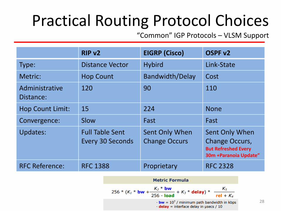
Practical Routing Protocol Choices “Common” IGP Protocols – VLSM Support
RIP v2 EIGRP (Cisco) OSPF v2
Type: Distance Vector Hybird Link-State
Metric: Hop Count Bandwidth/Delay Cost
Administrative Distance:
120 90 110
Hop Count Limit: 15 224 None
Convergence: Slow Fast Fast
Updates:
Full Table Sent Every 30 Seconds
Sent Only When Change Occurs
Sent Only When Change Occurs, But Refreshed Every 30m +Paranoia Update”
RFC Reference: RFC 1388 Proprietary RFC 2328
28

THE IP ADDRESS
29

IP Addressing “Rules”
• Each Network MUST Have a Unique Network ID
• Each Host MUST Have a Unique Host ID
• Every IP Address MUST Have a Subnet Mask – Implied for a Classful Network
– Explicit Stated for Classless Network
• The First & Last IP Address of a Network is Not Useable!
• Public Address Space: – Routable Over Global Internet
– Allocation Governed By IANA – Internet Assigned Number Authority
• Private Address Space: – Freely Assignable (network, organization)
– Can Never Be Routed Over Global Internet
30

The IPv4 Address • 32 Bit Binary Address and 32 Bit Binary Mask
• 232 Yields 4,294,967,296 Addresses
• 32 Bits Divided Into Four (4) Octets or Bytes
• Expressed in “Dotted Decimal” Notation
192
32 bit IP Address
1100000010101000110010011111110
168 100 254
11000000 10101000 1100100 11111110
Octet 1 Octet 2 Octet 3 Octet 4
4 Bytes
192.168.100.25431

2-Part IPv4 Address
32
192
32 bit IP Address
1100000010101000110010011111110
168 100 254
11000000 10101000 1100100 11111110
Subnet
Mask
Determines
Network
Address
Host
Address
Octet 1 Octet 2 Octet 3 Octet 4
4 Bytes

IPv4 Address Classes
33
NETWORK HOST HOST HOST
NETWORKNETWORK
NETWORKNETWORKNETWORK
HOSTHOST
HOST
Class A
Class D
Class C
Class E
Class B
Experimental
Multicast
32 bits
8 bits 8 bits8 bits8 bits
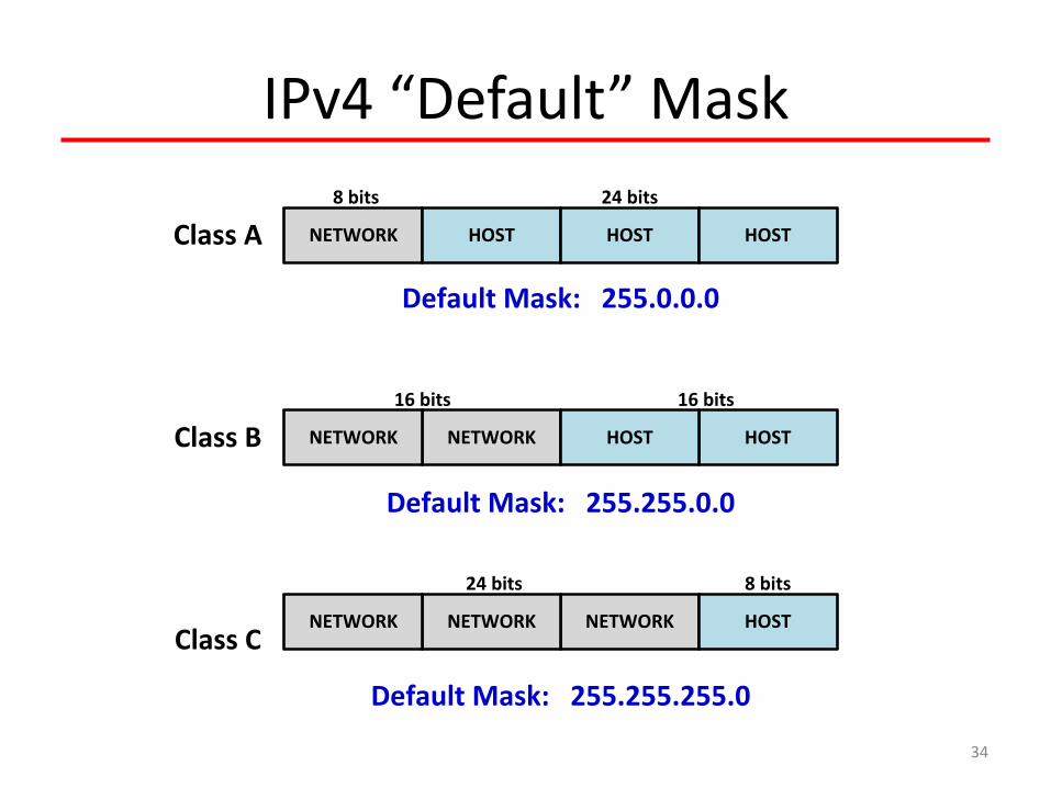
IPv4 “Default” Mask
34
NETWORK HOST HOST HOST
NETWORKNETWORK
NETWORKNETWORKNETWORK
HOSTHOST
HOST
Class A
Class C
Class B
8 bits
16 bits
Default Mask: 255.0.0.0
Default Mask: 255.255.255.0
Default Mask: 255.255.0.0
24 bits
16 bits
8 bits24 bits

Classful IPv4 Addressing 1 - 127 128 - 191 192 - 223First Octet Range
Default Mask
Host Bits
Network Bits
Available Hosts/Network
Available Networks
Network Range
Class B Class C
1.0.0.0 – 127.0.0.0
126
16,777,214
8
24
255.0.0.0
128.0.0.0 – 191.255.0.0
16,384
65,534
16
16
255.255.0.0
192.0.0.0 – 223.255.255.0
2,097,152
254
24
8
255.255.255.0
35

VLSM RFC 1009
• Variable Length Subnet Masking (VLSM)
– Host Addressing & Routing Inside a Routing Domain
– Allowed “Classless” Subnetting • Mask Information is Explicit – Must Be Specified
– Allows More Efficient Use of Address Space – Taylor Address Space to Fit Network Needs
– Allows You to Subnet a Subnet • Subnetting “Borrows” Host Bits to Create More Networks
VLSM
Allows Mask
To Be Moved 36

VLSM • Allows Mask to Be Determined on a “Bit Basis”
– Remember: Classful Addressing Specified Network/Host Boundary
– Classless Addressing Allows Network/Host Boundary to Be Specified at an Individual Bit
Octet 1 Octet 2 Octet 3 Octet 4
Octet 1 Octet 2 Octet 3 Octet 4
A B C
19 Subnet Mask Bits = 255.255.224.0
Network Host
Network Host
37

CIDR
RFC 1517, 1518, 1519, 1520
• Classless Interdomain Routing (CIDR)
– Class System No Longer Applies
– Routing Between Routing Domains
– Allows “Supernets” To Be Created
• Combining a Group of Class C Addresses Into a Single Block
– CIDR Notation (slanted notation): 192.168.100.254 /19
Mask:
11111111.11111111.11100000.00000000
255.255.224.0
38

IPv4 Address Mask Possible Formats
39
Classful Addressing: 192.168.100.254 (Implied Mask 255.255.255.0) VLSM Addressing: 192.168.100.254 255.255.224.0 (Explicit Mask 255.255.224.0 CIDR Notation : 192.168.100.254 /19
Number of Mask Bits
1 1 1
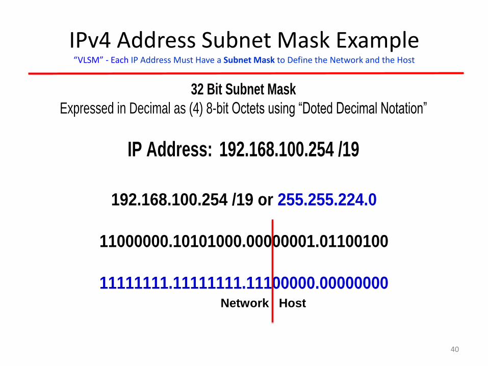
IPv4 Address Subnet Mask Example “VLSM” - Each IP Address Must Have a Subnet Mask to Define the Network and the Host
32 Bit Subnet Mask
Expressed in Decimal as (4) 8-bit Octets using “Doted Decimal Notation”
IP Address: 192.168.100.254 /19
192.168.100.254 /19 or 255.255.224.0
11000000.10101000.00000001.01100100
11111111.11111111.11100000.00000000Network Host
40
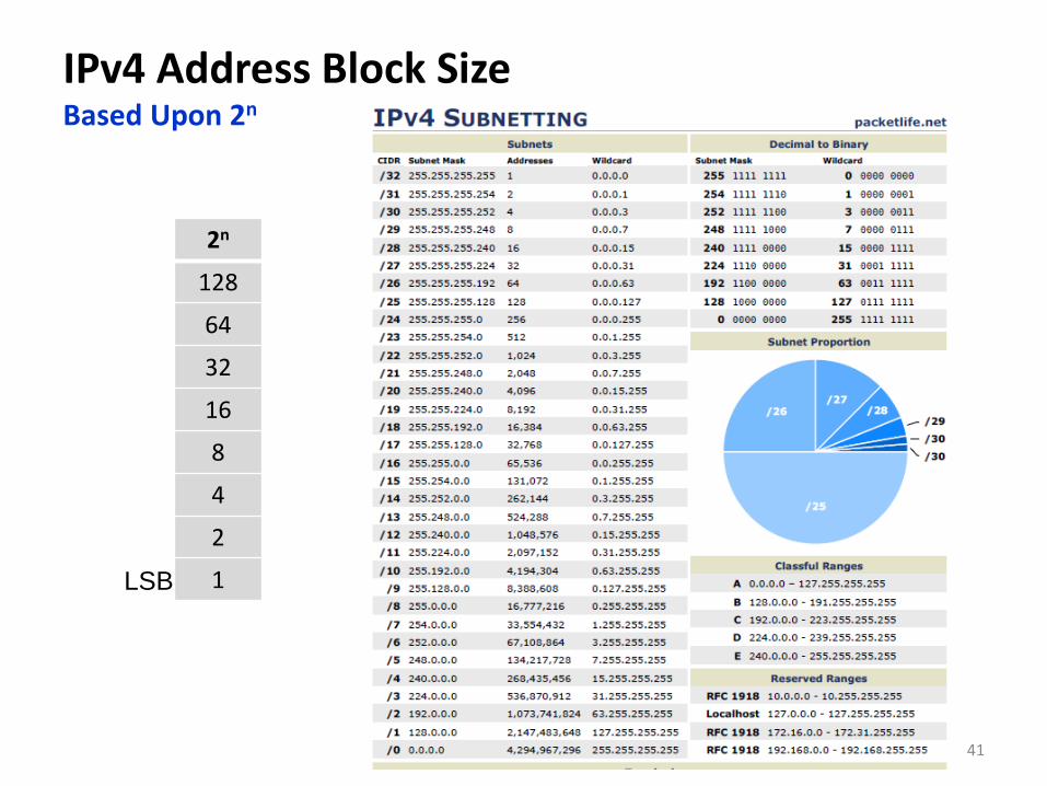
IPv4 Address Block Size Based Upon 2n
41
2n
128
64
32
16
8
4
2
1 LSB

All Valid IPv4 Subnet Masks
42
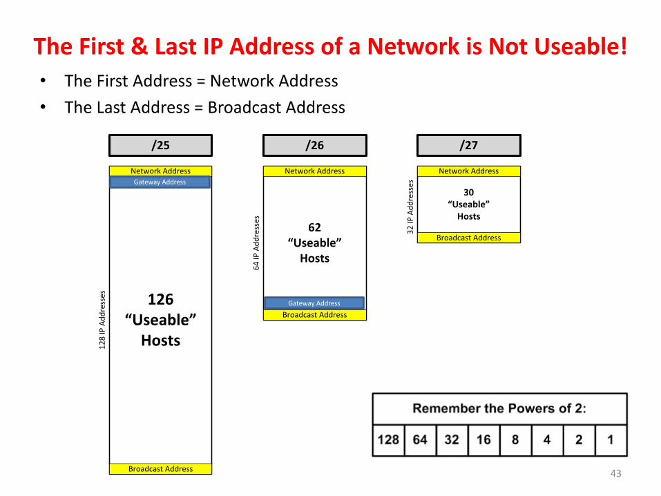
The First & Last IP Address of a Network is Not Useable! • The First Address = Network Address
• The Last Address = Broadcast Address
126 “Useable”
Hosts
/25
62 “Useable”
Hosts
30 “Useable”
Hosts
/26 /27
Network Address
Broadcast Address
Network Address Network Address
Broadcast Address
Broadcast Address
12
8 IP
Ad
dre
sses
32
IP A
dd
ress
es
64
IP A
dd
ress
es
Gateway Address
Gateway Address
43
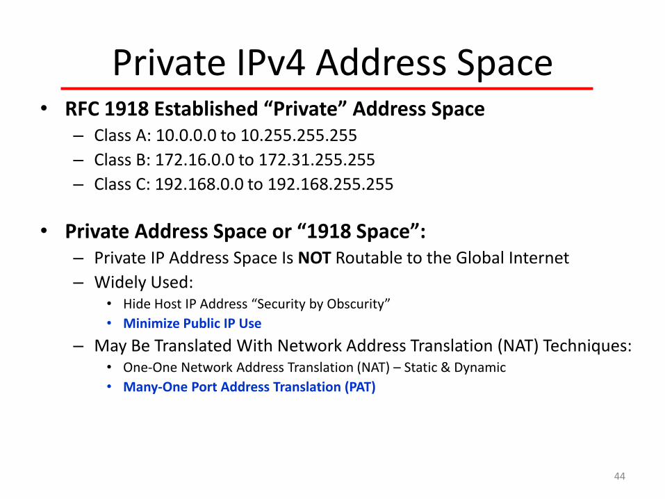
Private IPv4 Address Space • RFC 1918 Established “Private” Address Space
– Class A: 10.0.0.0 to 10.255.255.255
– Class B: 172.16.0.0 to 172.31.255.255
– Class C: 192.168.0.0 to 192.168.255.255
• Private Address Space or “1918 Space”: – Private IP Address Space Is NOT Routable to the Global Internet
– Widely Used: • Hide Host IP Address “Security by Obscurity”
• Minimize Public IP Use
– May Be Translated With Network Address Translation (NAT) Techniques: • One-One Network Address Translation (NAT) – Static & Dynamic
• Many-One Port Address Translation (PAT)
44

Network Address Translation – NAT RFC 3022
Inside
Network
(private)
Outside
Network
RFC 1918
Addressed Hosts
Public
Address
Space
(Usually)
Gateway Router
w/ NAT Services
• NAT Allows a Host Without a Valid Public IP Address to Communicate With a Host That Has a Public IP Address by Simply Changing the IP Addresses as Packet Passes Through the NAT Device
• Why Use?
– Conserve Public IPv4 Address Space
– Security by Obscurity (hide actual host IP address) - “Questionable Value”
• NAT Types:
– Static – One-to-One Translation
– Dynamic – Pool of Public Addresses Made Available to Outbound Traffic Client Traffic
– NAT Overloading or Port Address Translation (PAT) – Translates to a Single Public IP by Use of a Unique Port Number
45
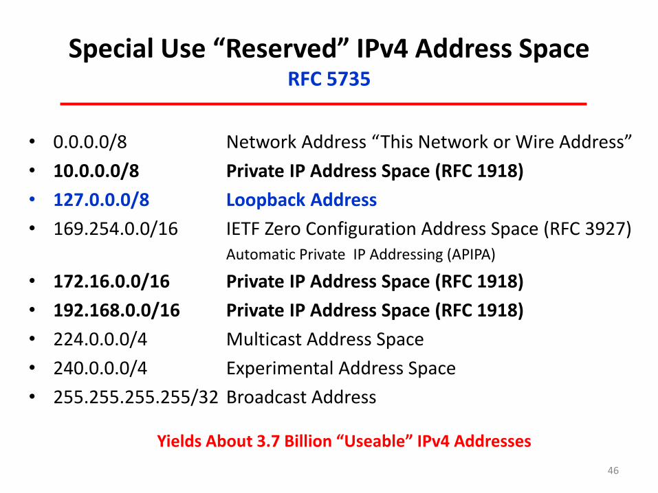
Special Use “Reserved” IPv4 Address Space RFC 5735
• 0.0.0.0/8 Network Address “This Network or Wire Address”
• 10.0.0.0/8 Private IP Address Space (RFC 1918)
• 127.0.0.0/8 Loopback Address
• 169.254.0.0/16 IETF Zero Configuration Address Space (RFC 3927) Automatic Private IP Addressing (APIPA)
• 172.16.0.0/16 Private IP Address Space (RFC 1918)
• 192.168.0.0/16 Private IP Address Space (RFC 1918)
• 224.0.0.0/4 Multicast Address Space
• 240.0.0.0/4 Experimental Address Space
• 255.255.255.255/32 Broadcast Address
Yields About 3.7 Billion “Useable” IPv4 Addresses
46
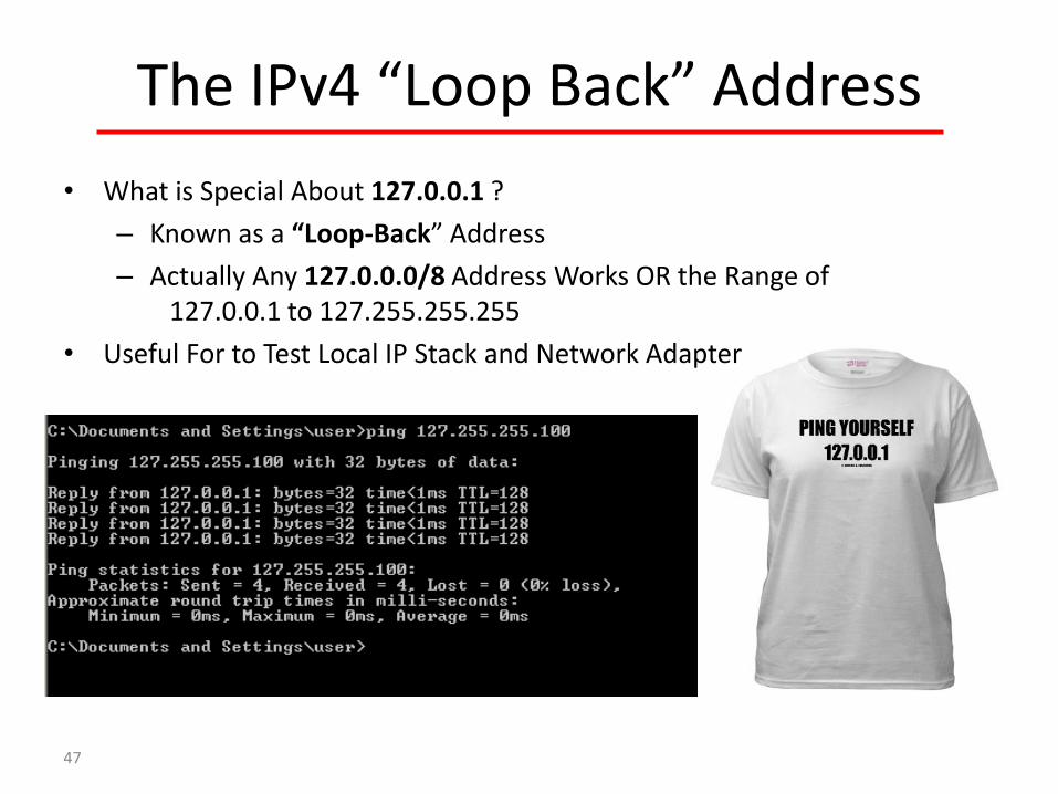
The IPv4 “Loop Back” Address
• What is Special About 127.0.0.1 ?
– Known as a “Loop-Back” Address
– Actually Any 127.0.0.0/8 Address Works OR the Range of 127.0.0.1 to 127.255.255.255
• Useful For to Test Local IP Stack and Network Adapter
47

Let’s Think About IPv6
48

IPv4 Address Depletion • As of February 2011 ALL ICANN IPv4 Address Space Assigned!
• Regional Registries Now Have Their Last Allocation!
http://www.potaroo.net/tools/ipv4/plotend.png
Updated:
7/18/17
49

“An Opportunity to Re-Engineer IPv4”
• Increased IP Address Space
• Header Simplification for Performance Increase
• Improved Authentication and Security
• Host Auto-Configuration
• Mobility Incorporated
50
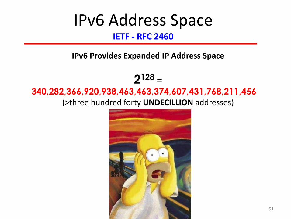
IPv6 Address Space IETF - RFC 2460
IPv6 Provides Expanded IP Address Space
2128 =
340,282,366,920,938,463,463,374,607,431,768,211,456 (>three hundred forty UNDECILLION addresses)
3.4 x 1038
51

The IPv6 Address
128-Bit Address Binary Format: 001001100000011110111000000000001111101010100000000000110010000110010101100110001000011110111100010010000010100011110001
52
Remember, a subnet mask is needed: CIDR format utilized:
2607:b800:faa:3:2195:9887:bc48:28f1 /64
Convert Each 16-bit Group to Hexadecimal: (separate with a colon)
2607:b800:0faa:0003:2195:9887:bc48:28f1
Subdivide Into Eight (8) 16-bit Groups: 0010011000000111 1011100000000000 0000111110101010 0000000000000011 0010000110010101 1001100010000111 1011110001001000 0010100011110001

Address Summarization 128-Bit Address Represented as a 32 Hexadecimal Digits
Subdivided Into Eight Groups (Fields, Chunks, Quads, Quartets) of Four Hexadecimal Digits
(separated by colon)
2001:0000:0000:0000:0DB8:8000:200C:417A or
2001:0:0:0:DB8:8000:200C:417A or
2001::DB8:8000:200C:417A
53 53
IPv6 Summarization Rules:
Delete Leading Zeros in Each Quad (or chunk or quartet) Replace Consecutive Zeros with “::” (but only once)

Version
(4)
Traffic Class
(8)
Flow Label
(20)
Payload Length
(16)
Source IP Address
(128)
Destination IP Address
(128)
Packet Payload
(Transport Layer Data)
32 bits
40
Bytes
Ipv6
Hop Limit
(8)
Next Header
(8)
Version
(4)
Header
(4)
Precedence / Type
(8)
Length
(16)
Identification
(16)
Flag
(3)
Offset
(13)
Time to Live
(8)
Protocol
(8)
Header Checksum
(16)
Source IP Address
(32)
Options & Padding
(0 or 32)
Destination IP Address
(32)
Packet Payload
(Transport Layer Data)
32 bits
20
Bytes
Ipv4
IPv6 Header Simplification
Fewer Fields & Fixed Header Size Result in Faster Packet Processing Providing Enhanced Routing Efficiency
54

IPv6 Address Types
• Unicast – Single Interface – Global Unicast Address – Unique-Local Unicast Address (non-Routable or Private) – Link-Local Unicast
• Multicast – One-to Many Mapping – Multicast Groups Established
• Anycast – One-to-Nearest Mapping – Interface Exists on Multiple Hosts – Packets Are Delivered to the “Closest, Nearest, or Lowest-Cost” Interface
• Global Anycast • Site-Local Anycast • Link-Local Anycast
• No Broadcast Address
• Special Addresses: – 0:0:0:0:0:0:0:0 – Unspecified Address – 0:0:0:0:0:0:0:1 – Loopback Address
55
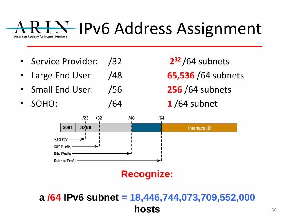
IPv6 Address Assignment
• Service Provider: /32 232 /64 subnets
• Large End User: /48 65,536 /64 subnets
• Small End User: /56 256 /64 subnets
• SOHO: /64 1 /64 subnet
Recognize:
a /64 IPv6 subnet = 18,446,744,073,709,552,000
hosts 56

Implementing IPv6?
IPv4
User
IPv4
only
IPv4
Based
Router
IPv4
Based
Router
IPv4
Ba
se
d N
etw
ork
NATIVE
Approach
IPv6
Ba
se
d N
etw
ork
IPv6
User
IPv6
only
IPv6
Based
Router
IPv6
Based
Router
IPv4
User
IPv4
only
IPv4
Ba
se
d N
etw
ork
IPv6 TUNNLED OVER IPv4
Approach
IPv6
User
IPv6
only
IPv4
& IP
v6
Ba
se
d N
etw
ork
DUAL - STACK
Approach
IPv6
UserIPv4
User
IPv4 & IPv6
IPv6
IPv6
IPv4 & IPv6
Based Router
IPv4 & IPv6
Based Router
IPv6 Packets
Tunneled Over
IPv4 Network
57

58
Windows XP Apple IOS

Want to Learn More?
IPv6 Enable Your Home Network or “Sandbox” Network
But, My Provider is Not IPv6
Enabled!
Then “Tunnel” to an IPv6 Provider:
http://www.tunnelbroker.net
59
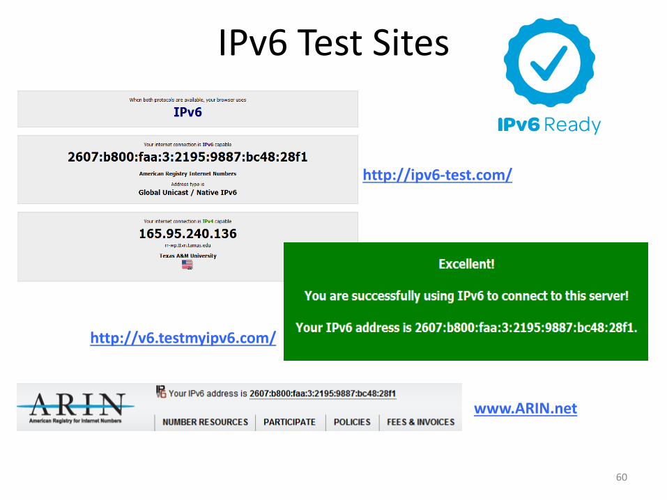
IPv6 Test Sites
http://ipv6-test.com/
http://v6.testmyipv6.com/
www.ARIN.net
60

An Ipv6 Address You Can Remember
The IPv6 Loopback Address
::1 Summarized from: 0:0:0:0:0:0:0:1
61

Some Final IPv6 Trivia
What Happened to Version 5 or IPv5 of the Internet Protocol?
“IPv5 Simply Does Not Exist!” Version 5 was intentionally skipped to avoid confusion, or at least to rectify it. The problem with version 5 relates to an experimental TCP/IP protocol called the Internet Stream Protocol, Version 2, originally defined in RFC 1190. This protocol was originally seen by some as being a peer of IP at the Internet Layer in the TCP/IP architecture and these packets were assigned IP version 5 to differentiate them from “normal” IPv4 packets. This protocol never went anywhere, but to be absolutely sure that there would be no confusion, version 5 was skipped over in favor of version 6.”
62
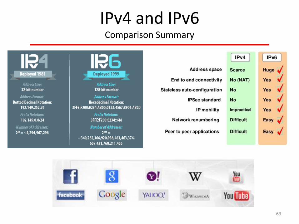
IPv4 and IPv6 Comparison Summary
63

64
https://www.google.com/intl/en/ipv6/statistics.html

Vinton Cerf “One of the Fathers of the Internet”
"Who the hell knew how much address space we needed for an experiment?“ “The experiment has not ended”
“Vint” Cerf comments on his & colleagues 1977 decision to use 32-bit IP Numbers
65
TAKEAWAYS, REFERENCES, & QUESTIONS
66
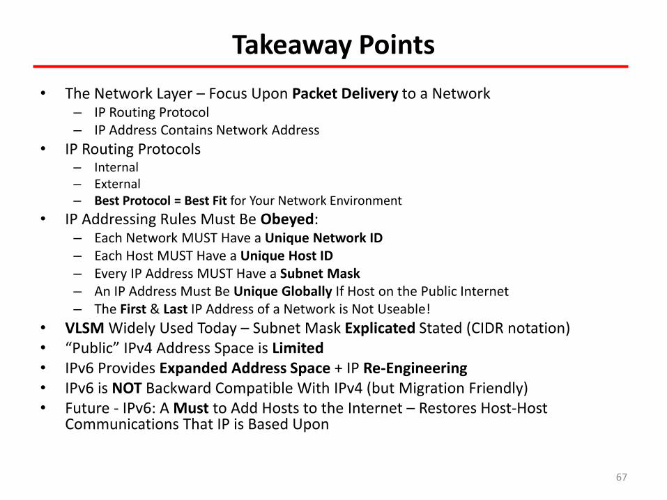
Takeaway Points
• The Network Layer – Focus Upon Packet Delivery to a Network – IP Routing Protocol – IP Address Contains Network Address
• IP Routing Protocols – Internal – External – Best Protocol = Best Fit for Your Network Environment
• IP Addressing Rules Must Be Obeyed: – Each Network MUST Have a Unique Network ID – Each Host MUST Have a Unique Host ID – Every IP Address MUST Have a Subnet Mask – An IP Address Must Be Unique Globally If Host on the Public Internet – The First & Last IP Address of a Network is Not Useable!
• VLSM Widely Used Today – Subnet Mask Explicated Stated (CIDR notation) • “Public” IPv4 Address Space is Limited • IPv6 Provides Expanded Address Space + IP Re-Engineering • IPv6 is NOT Backward Compatible With IPv4 (but Migration Friendly) • Future - IPv6: A Must to Add Hosts to the Internet – Restores Host-Host
Communications That IP is Based Upon
67

Packet Flow Through Network
00:06:5B:01:02:03
192.168.1.101
00:06:5B:11:22:33
192.168.1.104
00:00:0C:C1:00:01
192.168.1.102
00:00:0C:C1:00:30
192.168.1.103
00:00:0C:C1:00:20
192.168.100.102
00:00:0C:C1:00:10
192.168.100.101
Destination MAC
00:00:0C:C1:00:20
Source MAC
00:00:0C:C1:00:10
Source IP
192.168.1.101
Destination IP
192.168.1.104 DATAP
R
E
C
R
C
T
Y
P
E
Destination MAC
00:00:0C:C1:00:01
Source MAC
00:06:5B:01:02:03
Source IP
192.168.1.101
Destination IP
192.168.1.104 DATAP
R
E
C
R
C
T
Y
P
E
Destination MAC
00:06:5B:11:22:33
Source MAC
00:00:0C:C1:00:30
Source IP
192.168.1.101
Destination IP
192.168.1.104 DATAP
R
E
C
R
C
T
Y
P
E
HOST A HOST B
IP Address Does Not Change As Packet
Passes Through the Network (except if NAT is involved)
68
My Favorite Reference Texts:
69


71

Thank You for Attending!
Wayne M. Pecena [email protected]
979.845.5662
72
Don’t Miss: Part 4 - Building a Segmented IP Network Focused On Performance & Security-
July 25, 2017