fusion 360 (case study) creating a lab power supply
TRANSCRIPT

Jorge Garcia
Fusion 360 Community Manager
Heath Houghton
Product Manager for Fluid Simulation Products
Fusion 360 (Case Study)Creating a Lab Power Supply

About the speaker
Jorge Garcia
I'm a Community Manager for Fusion 360
Electronics/EAGLE, here at Autodesk. I have been
working with EAGLE for 10 years. I earned my
Bachelor’s Degree in Electrical Engineering from
Florida International University in 2008. I love
electronics and building projects focusing on power and
control applications. I have an affinity for embedded
systems and programming.

About the speaker
Heath Houghton
Heath Houghton is the product manager for fluids simulation
products. As Product Manager, Heath guides the development
efforts and roadmap decisions for flow and thermal simulation
projects. Heath joined Autodesk with the acquisition of Blue Ridge
Numerics CFdesign. He was in a technical role with Blue Ridge
Numerics for several years and he continued in that role with
Autodesk before transitioning to Product Manager. Heath has over
20 years of experience with both fluids and structural simulation
tools. In his spare time, Heath enjoys archery and training his bird
dogs.

Design Theory of Operation

Schematic Overview
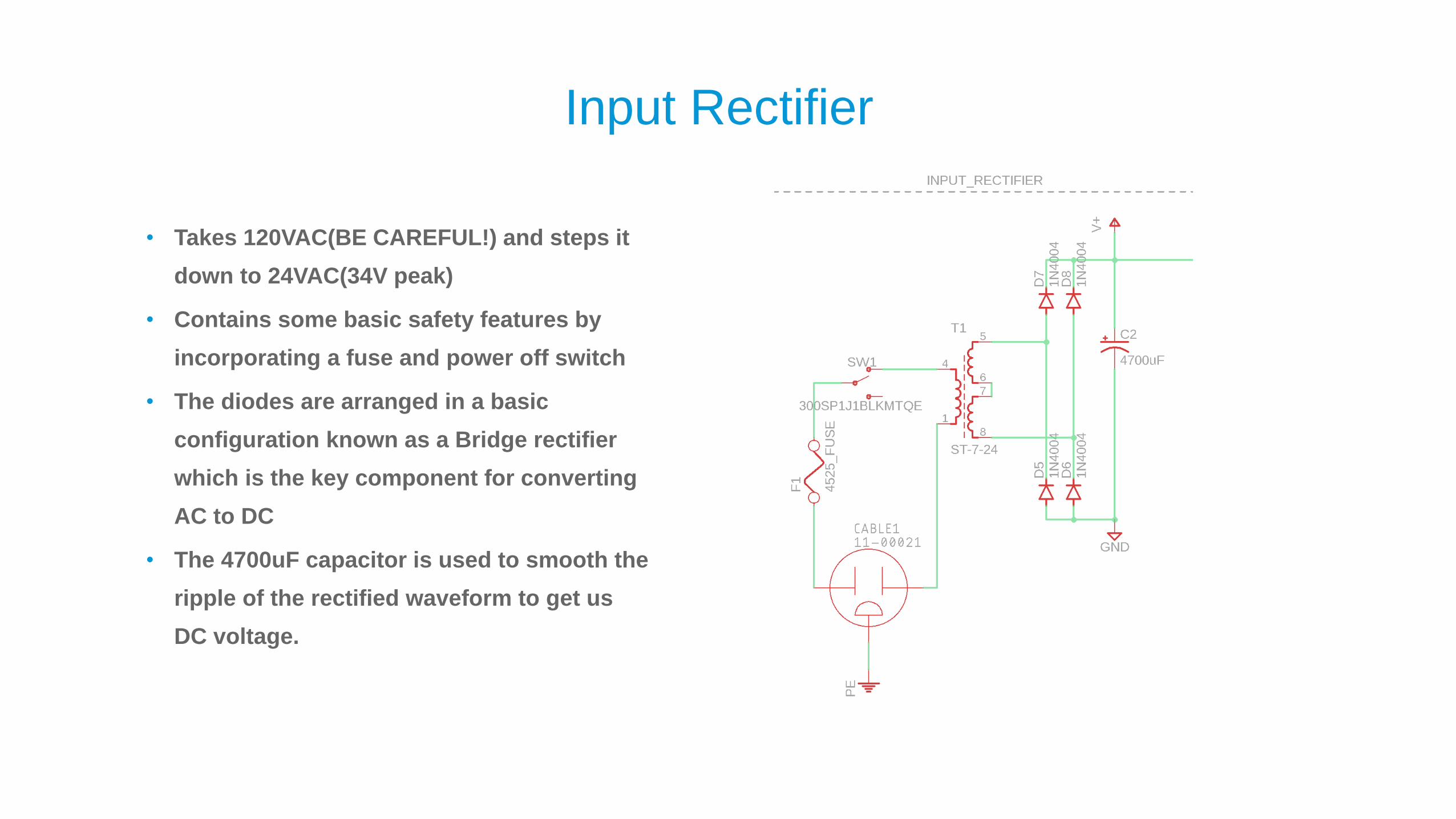
Input Rectifier
• Takes 120VAC(BE CAREFUL!) and steps it
down to 24VAC(34V peak)
• Contains some basic safety features by
incorporating a fuse and power off switch
• The diodes are arranged in a basic
configuration known as a Bridge rectifier
which is the key component for converting
AC to DC
• The 4700uF capacitor is used to smooth the
ripple of the rectified waveform to get us
DC voltage.
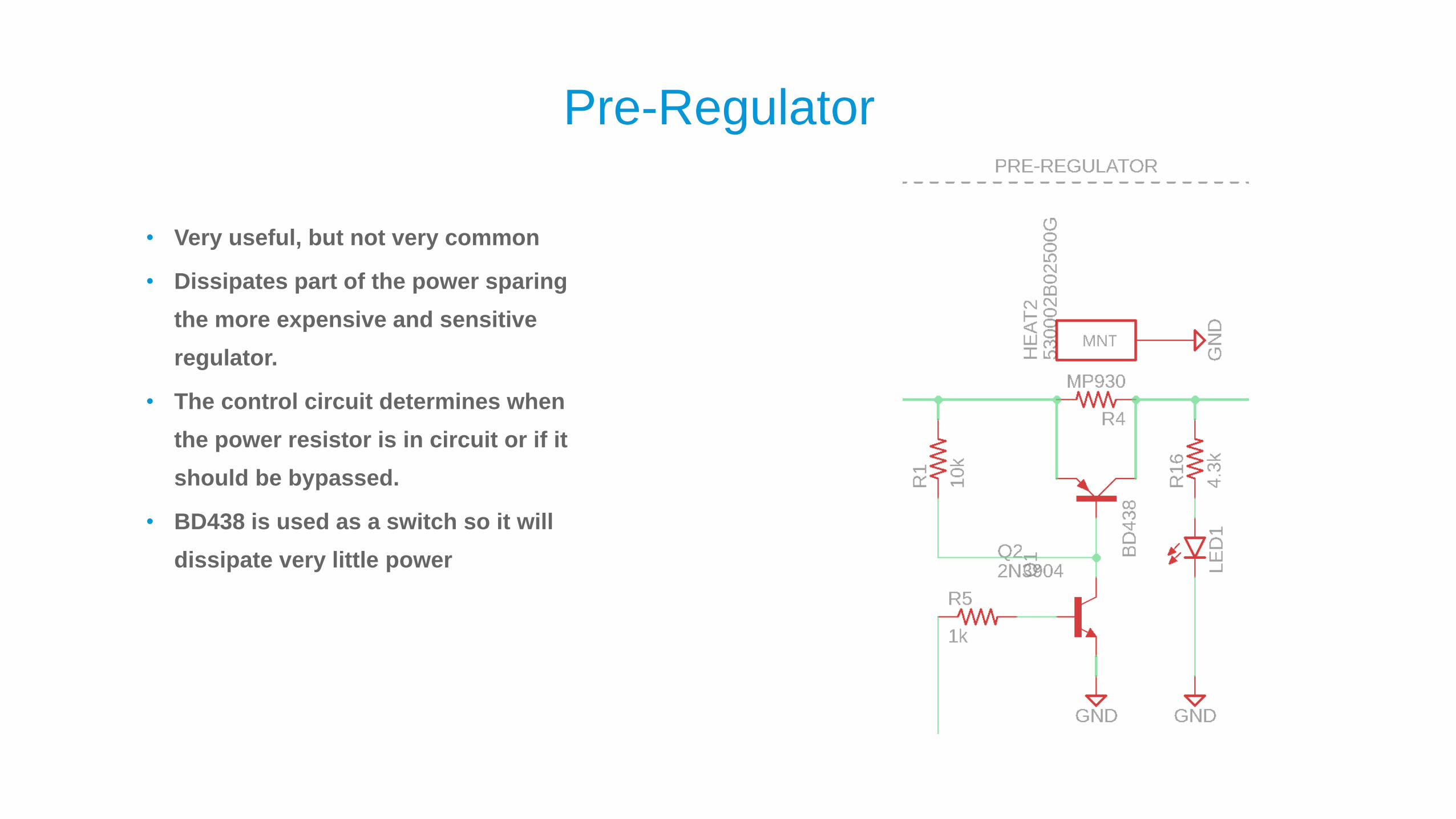
Pre-Regulator
• Very useful, but not very common
• Dissipates part of the power sparing
the more expensive and sensitive
regulator.
• The control circuit determines when
the power resistor is in circuit or if it
should be bypassed.
• BD438 is used as a switch so it will
dissipate very little power
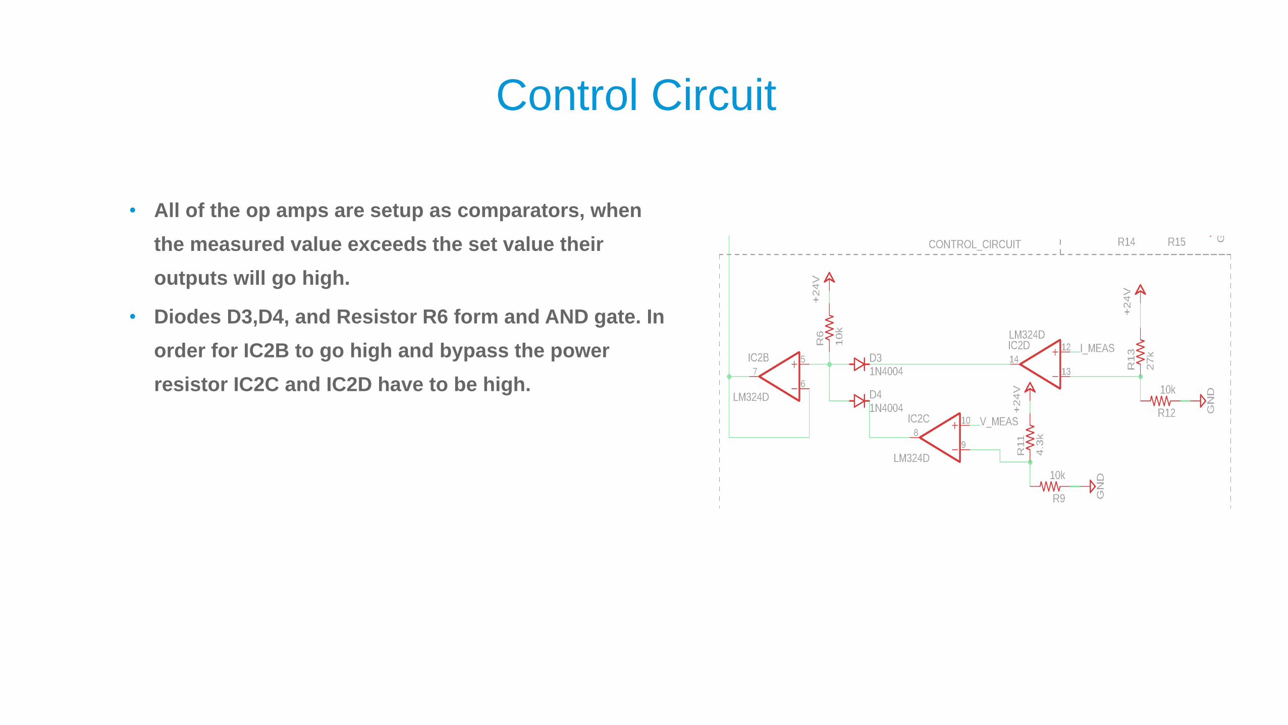
Control Circuit
• All of the op amps are setup as comparators, when
the measured value exceeds the set value their
outputs will go high.
• Diodes D3,D4, and Resistor R6 form and AND gate. In
order for IC2B to go high and bypass the power
resistor IC2C and IC2D have to be high.

How to determine thresholds- MATH
• From the schematic we can determine that the power dissipation of the regulator is defined by
• 𝑷𝒓𝒆𝒈 = 𝑽𝒉 − 𝑽𝒐𝒖𝒕 𝑰 − 𝑹𝑰𝟐
o The Maximum dissipation can be calculated by taking the derivative and setting that to 0. For a given R value we
can find the current at which max dissipation occurs plug it into the above equation and find out the peak dissipation
for a given power resistor value and output voltage.
▪ 𝐼 =𝑉ℎ−𝑉𝑜𝑢𝑡
2𝑅is the current that will yield the maximum power dissipation in the regulator
• Determining the optimal balance is a tradeoff between the resistor value and being able to provide the
necessary output voltage.
o A large resistor will allow us to have low dissipation in the Regulator but will limit what output current and voltages
we can output.

How to determine thresholds - VISUALLY
• The top table shows the regulator dissipation
with the resistor in-circuit for every
combination of current and output voltage
o All cells larger than zero are green. Cells less
than 0 are unachievable. The fringes have to
confirmed to make sure they will work since the
regulator needs some overhead
• Bottom table is no resistor in circuit
o All cells whose dissipation is greater than 25W
are red
• Make sure all red combinations can have the
resistor in circuit. The unobtainable regions in
the top table require the resistor to be
bypassed
R 10
VH 34
V(volts) | I(amps)> Dissipation of Regulator with a Resistor Pre-reg
0.1 0.2 0.3 0.4 0.5 0.6 0.7 0.8 0.9 1 1.1 1.2 1.3 1.4 1.5
1.25 3.175 6.15 8.925 11.5 13.875 16.05 18.025 19.8 21.375 22.75 23.925 24.9 25.675 26.25 26.625
2.5 3.05 5.9 8.55 11 13.25 15.3 17.15 18.8 20.25 21.5 22.55 23.4 24.05 24.5 24.75
3.75 2.925 5.65 8.175 10.5 12.625 14.55 16.275 17.8 19.125 20.25 21.175 21.9 22.425 22.75 22.875
5 2.8 5.4 7.8 10 12 13.8 15.4 16.8 18 19 19.8 20.4 20.8 21 21
6.25 2.675 5.15 7.425 9.5 11.375 13.05 14.525 15.8 16.875 17.75 18.425 18.9 19.175 19.25 19.125
7.5 2.55 4.9 7.05 9 10.75 12.3 13.65 14.8 15.75 16.5 17.05 17.4 17.55 17.5 17.25
8.75 2.425 4.65 6.675 8.5 10.125 11.55 12.775 13.8 14.625 15.25 15.675 15.9 15.925 15.75 15.375
10 2.3 4.4 6.3 8 9.5 10.8 11.9 12.8 13.5 14 14.3 14.4 14.3 14 13.5
11.25 2.175 4.15 5.925 7.5 8.875 10.05 11.025 11.8 12.375 12.75 12.925 12.9 12.675 12.25 11.625
12.5 2.05 3.9 5.55 7 8.25 9.3 10.15 10.8 11.25 11.5 11.55 11.4 11.05 10.5 9.75
13.75 1.925 3.65 5.175 6.5 7.625 8.55 9.275 9.8 10.125 10.25 10.175 9.9 9.425 8.75 7.875
15 1.8 3.4 4.8 6 7 7.8 8.4 8.8 9 9 8.8 8.4 7.8 7 6
16.25 1.675 3.15 4.425 5.5 6.375 7.05 7.525 7.8 7.875 7.75 7.425 6.9 6.175 5.25 4.125
17.5 1.55 2.9 4.05 5 5.75 6.3 6.65 6.8 6.75 6.5 6.05 5.4 4.55 3.5 2.25
18.75 1.425 2.65 3.675 4.5 5.125 5.55 5.775 5.8 5.625 5.25 4.675 3.9 2.925 1.75 0.375
20 1.3 2.4 3.3 4 4.5 4.8 4.9 4.8 4.5 4 3.3 2.4 1.3 0 -1.5
21.25 1.175 2.15 2.925 3.5 3.875 4.05 4.025 3.8 3.375 2.75 1.925 0.9 -0.325 -1.75 -3.375
22.5 1.05 1.9 2.55 3 3.25 3.3 3.15 2.8 2.25 1.5 0.55 -0.6 -1.95 -3.5 -5.25
23.75 0.925 1.65 2.175 2.5 2.625 2.55 2.275 1.8 1.125 0.25 -0.825 -2.1 -3.575 -5.25 -7.125
25 0.8 1.4 1.8 2 2 1.8 1.4 0.8 0 -1 -2.2 -3.6 -5.2 -7 -9
0.1 0.2 0.3 0.4 0.5 0.6 0.7 0.8 0.9 1 1.1 1.2 1.3 1.4 1.5
1.25 3.275 6.55 9.825 13.1 16.375 19.65 22.925 26.2 29.475 32.75 36.025 39.3 42.575 45.85 49.125
2.5 3.15 6.3 9.45 12.6 15.75 18.9 22.05 25.2 28.35 31.5 34.65 37.8 40.95 44.1 47.25
3.75 3.025 6.05 9.075 12.1 15.125 18.15 21.175 24.2 27.225 30.25 33.275 36.3 39.325 42.35 45.375
5 2.9 5.8 8.7 11.6 14.5 17.4 20.3 23.2 26.1 29 31.9 34.8 37.7 40.6 43.5
6.25 2.775 5.55 8.325 11.1 13.875 16.65 19.425 22.2 24.975 27.75 30.525 33.3 36.075 38.85 41.625
7.5 2.65 5.3 7.95 10.6 13.25 15.9 18.55 21.2 23.85 26.5 29.15 31.8 34.45 37.1 39.75
8.75 2.525 5.05 7.575 10.1 12.625 15.15 17.675 20.2 22.725 25.25 27.775 30.3 32.825 35.35 37.875
10 2.4 4.8 7.2 9.6 12 14.4 16.8 19.2 21.6 24 26.4 28.8 31.2 33.6 36
11.25 2.275 4.55 6.825 9.1 11.375 13.65 15.925 18.2 20.475 22.75 25.025 27.3 29.575 31.85 34.125
12.5 2.15 4.3 6.45 8.6 10.75 12.9 15.05 17.2 19.35 21.5 23.65 25.8 27.95 30.1 32.25
13.75 2.025 4.05 6.075 8.1 10.125 12.15 14.175 16.2 18.225 20.25 22.275 24.3 26.325 28.35 30.375
15 1.9 3.8 5.7 7.6 9.5 11.4 13.3 15.2 17.1 19 20.9 22.8 24.7 26.6 28.5
16.25 1.775 3.55 5.325 7.1 8.875 10.65 12.425 14.2 15.975 17.75 19.525 21.3 23.075 24.85 26.625
17.5 1.65 3.3 4.95 6.6 8.25 9.9 11.55 13.2 14.85 16.5 18.15 19.8 21.45 23.1 24.75
18.75 1.525 3.05 4.575 6.1 7.625 9.15 10.675 12.2 13.725 15.25 16.775 18.3 19.825 21.35 22.875
20 1.4 2.8 4.2 5.6 7 8.4 9.8 11.2 12.6 14 15.4 16.8 18.2 19.6 21
21.25 1.275 2.55 3.825 5.1 6.375 7.65 8.925 10.2 11.475 12.75 14.025 15.3 16.575 17.85 19.125
22.5 1.15 2.3 3.45 4.6 5.75 6.9 8.05 9.2 10.35 11.5 12.65 13.8 14.95 16.1 17.25
23.75 1.025 2.05 3.075 4.1 5.125 6.15 7.175 8.2 9.225 10.25 11.275 12.3 13.325 14.35 15.375
25 0.9 1.8 2.7 3.6 4.5 5.4 6.3 7.2 8.1 9 9.9 10.8 11.7 12.6 13.5
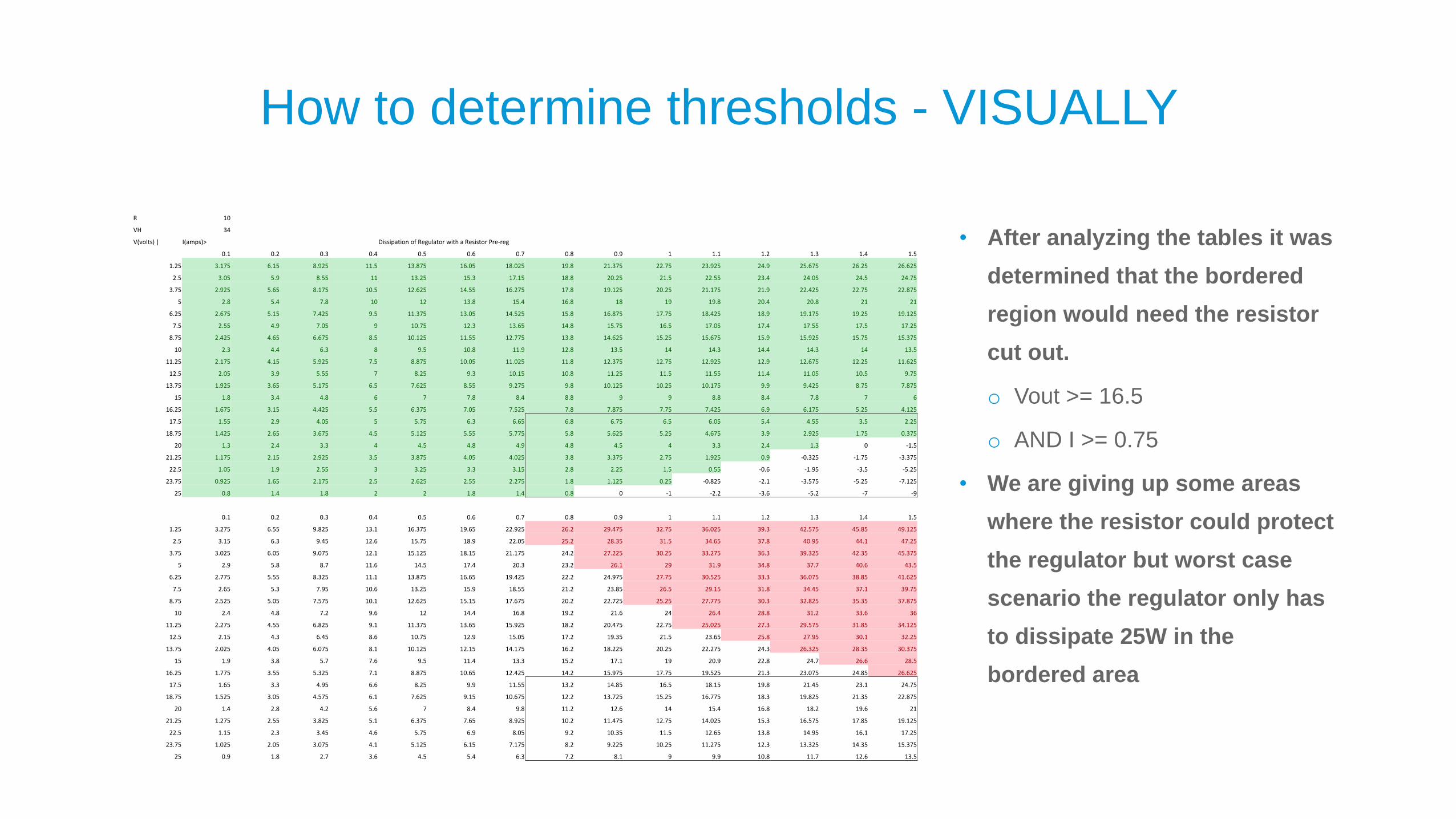
How to determine thresholds - VISUALLY
• After analyzing the tables it was
determined that the bordered
region would need the resistor
cut out.
o Vout >= 16.5
o AND I >= 0.75
• We are giving up some areas
where the resistor could protect
the regulator but worst case
scenario the regulator only has
to dissipate 25W in the
bordered area
R 10
VH 34
V(volts) | I(amps)> Dissipation of Regulator with a Resistor Pre-reg
0.1 0.2 0.3 0.4 0.5 0.6 0.7 0.8 0.9 1 1.1 1.2 1.3 1.4 1.5
1.25 3.175 6.15 8.925 11.5 13.875 16.05 18.025 19.8 21.375 22.75 23.925 24.9 25.675 26.25 26.625
2.5 3.05 5.9 8.55 11 13.25 15.3 17.15 18.8 20.25 21.5 22.55 23.4 24.05 24.5 24.75
3.75 2.925 5.65 8.175 10.5 12.625 14.55 16.275 17.8 19.125 20.25 21.175 21.9 22.425 22.75 22.875
5 2.8 5.4 7.8 10 12 13.8 15.4 16.8 18 19 19.8 20.4 20.8 21 21
6.25 2.675 5.15 7.425 9.5 11.375 13.05 14.525 15.8 16.875 17.75 18.425 18.9 19.175 19.25 19.125
7.5 2.55 4.9 7.05 9 10.75 12.3 13.65 14.8 15.75 16.5 17.05 17.4 17.55 17.5 17.25
8.75 2.425 4.65 6.675 8.5 10.125 11.55 12.775 13.8 14.625 15.25 15.675 15.9 15.925 15.75 15.375
10 2.3 4.4 6.3 8 9.5 10.8 11.9 12.8 13.5 14 14.3 14.4 14.3 14 13.5
11.25 2.175 4.15 5.925 7.5 8.875 10.05 11.025 11.8 12.375 12.75 12.925 12.9 12.675 12.25 11.625
12.5 2.05 3.9 5.55 7 8.25 9.3 10.15 10.8 11.25 11.5 11.55 11.4 11.05 10.5 9.75
13.75 1.925 3.65 5.175 6.5 7.625 8.55 9.275 9.8 10.125 10.25 10.175 9.9 9.425 8.75 7.875
15 1.8 3.4 4.8 6 7 7.8 8.4 8.8 9 9 8.8 8.4 7.8 7 6
16.25 1.675 3.15 4.425 5.5 6.375 7.05 7.525 7.8 7.875 7.75 7.425 6.9 6.175 5.25 4.125
17.5 1.55 2.9 4.05 5 5.75 6.3 6.65 6.8 6.75 6.5 6.05 5.4 4.55 3.5 2.25
18.75 1.425 2.65 3.675 4.5 5.125 5.55 5.775 5.8 5.625 5.25 4.675 3.9 2.925 1.75 0.375
20 1.3 2.4 3.3 4 4.5 4.8 4.9 4.8 4.5 4 3.3 2.4 1.3 0 -1.5
21.25 1.175 2.15 2.925 3.5 3.875 4.05 4.025 3.8 3.375 2.75 1.925 0.9 -0.325 -1.75 -3.375
22.5 1.05 1.9 2.55 3 3.25 3.3 3.15 2.8 2.25 1.5 0.55 -0.6 -1.95 -3.5 -5.25
23.75 0.925 1.65 2.175 2.5 2.625 2.55 2.275 1.8 1.125 0.25 -0.825 -2.1 -3.575 -5.25 -7.125
25 0.8 1.4 1.8 2 2 1.8 1.4 0.8 0 -1 -2.2 -3.6 -5.2 -7 -9
0.1 0.2 0.3 0.4 0.5 0.6 0.7 0.8 0.9 1 1.1 1.2 1.3 1.4 1.5
1.25 3.275 6.55 9.825 13.1 16.375 19.65 22.925 26.2 29.475 32.75 36.025 39.3 42.575 45.85 49.125
2.5 3.15 6.3 9.45 12.6 15.75 18.9 22.05 25.2 28.35 31.5 34.65 37.8 40.95 44.1 47.25
3.75 3.025 6.05 9.075 12.1 15.125 18.15 21.175 24.2 27.225 30.25 33.275 36.3 39.325 42.35 45.375
5 2.9 5.8 8.7 11.6 14.5 17.4 20.3 23.2 26.1 29 31.9 34.8 37.7 40.6 43.5
6.25 2.775 5.55 8.325 11.1 13.875 16.65 19.425 22.2 24.975 27.75 30.525 33.3 36.075 38.85 41.625
7.5 2.65 5.3 7.95 10.6 13.25 15.9 18.55 21.2 23.85 26.5 29.15 31.8 34.45 37.1 39.75
8.75 2.525 5.05 7.575 10.1 12.625 15.15 17.675 20.2 22.725 25.25 27.775 30.3 32.825 35.35 37.875
10 2.4 4.8 7.2 9.6 12 14.4 16.8 19.2 21.6 24 26.4 28.8 31.2 33.6 36
11.25 2.275 4.55 6.825 9.1 11.375 13.65 15.925 18.2 20.475 22.75 25.025 27.3 29.575 31.85 34.125
12.5 2.15 4.3 6.45 8.6 10.75 12.9 15.05 17.2 19.35 21.5 23.65 25.8 27.95 30.1 32.25
13.75 2.025 4.05 6.075 8.1 10.125 12.15 14.175 16.2 18.225 20.25 22.275 24.3 26.325 28.35 30.375
15 1.9 3.8 5.7 7.6 9.5 11.4 13.3 15.2 17.1 19 20.9 22.8 24.7 26.6 28.5
16.25 1.775 3.55 5.325 7.1 8.875 10.65 12.425 14.2 15.975 17.75 19.525 21.3 23.075 24.85 26.625
17.5 1.65 3.3 4.95 6.6 8.25 9.9 11.55 13.2 14.85 16.5 18.15 19.8 21.45 23.1 24.75
18.75 1.525 3.05 4.575 6.1 7.625 9.15 10.675 12.2 13.725 15.25 16.775 18.3 19.825 21.35 22.875
20 1.4 2.8 4.2 5.6 7 8.4 9.8 11.2 12.6 14 15.4 16.8 18.2 19.6 21
21.25 1.275 2.55 3.825 5.1 6.375 7.65 8.925 10.2 11.475 12.75 14.025 15.3 16.575 17.85 19.125
22.5 1.15 2.3 3.45 4.6 5.75 6.9 8.05 9.2 10.35 11.5 12.65 13.8 14.95 16.1 17.25
23.75 1.025 2.05 3.075 4.1 5.125 6.15 7.175 8.2 9.225 10.25 11.275 12.3 13.325 14.35 15.375
25 0.9 1.8 2.7 3.6 4.5 5.4 6.3 7.2 8.1 9 9.9 10.8 11.7 12.6 13.5
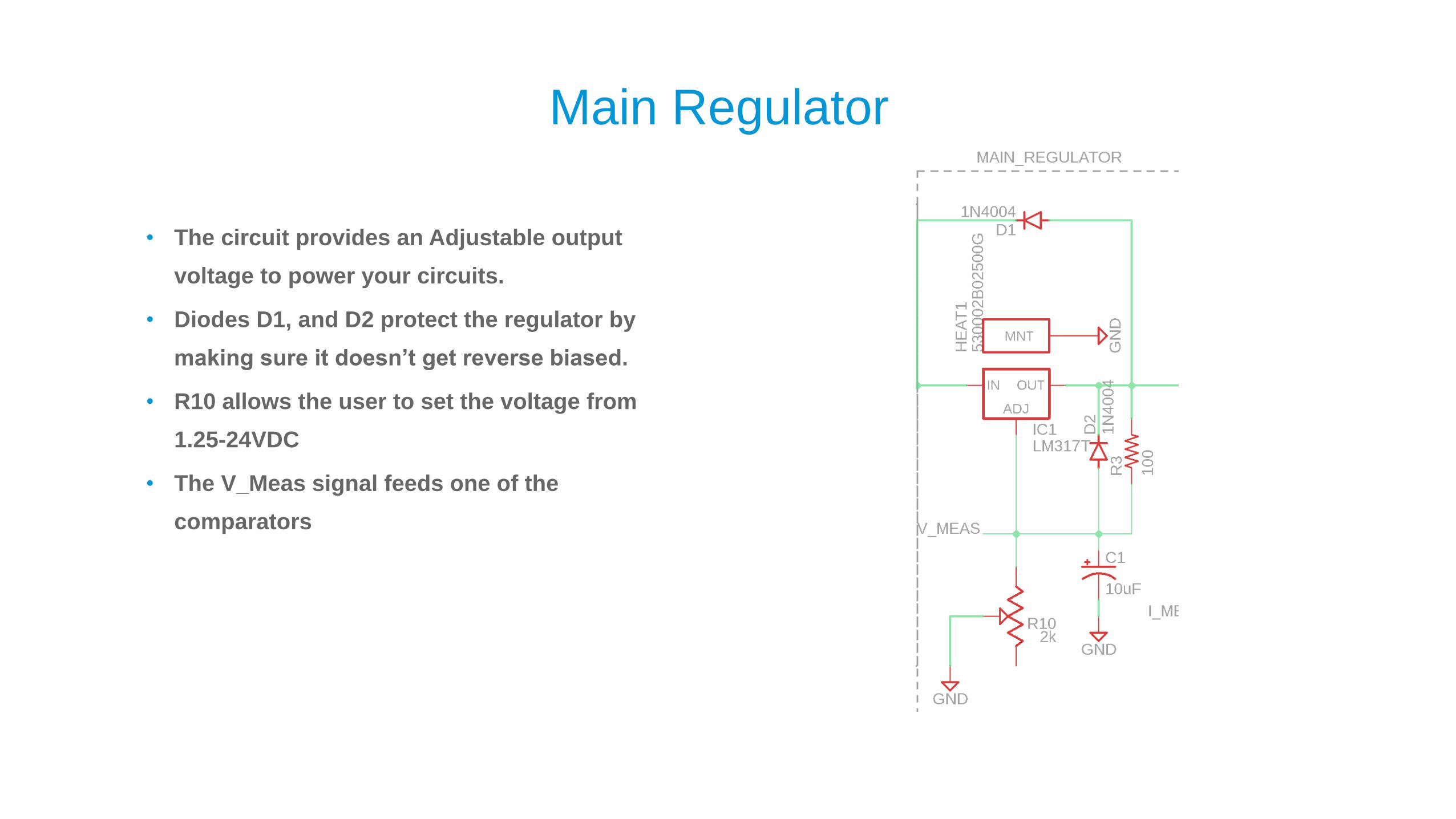
Main Regulator
• The circuit provides an Adjustable output
voltage to power your circuits.
• Diodes D1, and D2 protect the regulator by
making sure it doesn’t get reverse biased.
• R10 allows the user to set the voltage from
1.25-24VDC
• The V_Meas signal feeds one of the
comparators

Current Measurement
• The current measured signal feeds the other
comparator in the control circuit.
• R8,R14,R15 could technically be replaced with a
30k resistor, however sometimes especially in
large scale production it’s more cost effective to
limit the number of different component values
and order a larger quantity of the limited subset.
This is a good example.
• The voltage developed across R2, is amplified
and turned into a voltage by IC2A and Q4

How Fusion Electronics speeds up design
Collaboration on another level
• All data is versioned controlled
o You can recover from any bad saves by promoting a previous version
• All team members have access to the latest version of the data in real-time
o Allows for easy communication of changes
o Engineers from different disciplines can effectively work together
▪ ECAD-MCAD Workflows
▪ E-cooling simulation

Advanced Routing Features
• This power supply circuitry operates near DC
o From an electronics point of the view; all interconnects are transparent and intrinsic(aka parasitic)
impedances can be ignored
o This means that the layout itself is non-critical(generally speaking) and is a good candidate for a first time
PCB since the design requirements aren’t difficult to meet. We just have to make sure the traces are thick
enough to handle the current.
o This also means that we can leverage more of the automation that Fusion 360 Electronics/EAGLE provide to
speed up our design

Simplified Manufacturing Process
• The CAM processor export gives a gentle introduction to generating Gerber files and drill files since it
covers most use cases.
o With one click you can generate all your manufacturing data and send it to your manufacturer
o It analyzes your design and picks the most suitable template.

Demonstration
Please watch the demonstration here:https://drive.autodesk.com/new/de29810b9/shares/SH56a43QTfd62c1cd968b3008281353a8000
Or watch the demonstration in context at our class at AU2020

ECAD-MCAD Workflows
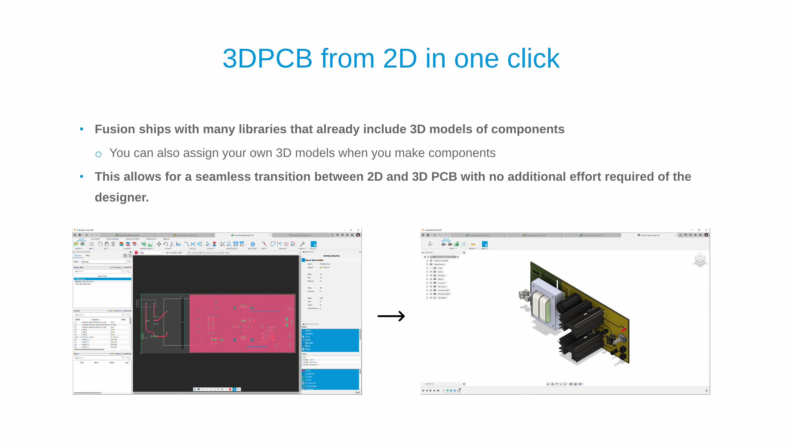
3DPCB from 2D in one click
• Fusion ships with many libraries that already include 3D models of components
o You can also assign your own 3D models when you make components
• This allows for a seamless transition between 2D and 3D PCB with no additional effort required of the
designer.

Designing an Enclosure from the 3D PCB
• 2 Main workflows
o Use PCB as basis for enclosure
▪ Insert the PCB into a new design and then draw the enclosure.
o Use the enclosure as the basis for the PCB
▪ PCB derive workflow allows the enclosure to drive the PCB design
• For this design we used the first workflow

Demonstration
Watch demo video here:https://drive.autodesk.com/new/de29810b9/shares/SH56a43QTfd62c1cd968a521b4e4325eb4e5
Or watch it in context at our class in AU2020

E-cooling

Baseline Enclosure
The transistor is not attached to a heat sink
• Natural convection
• 50 watt heat generation
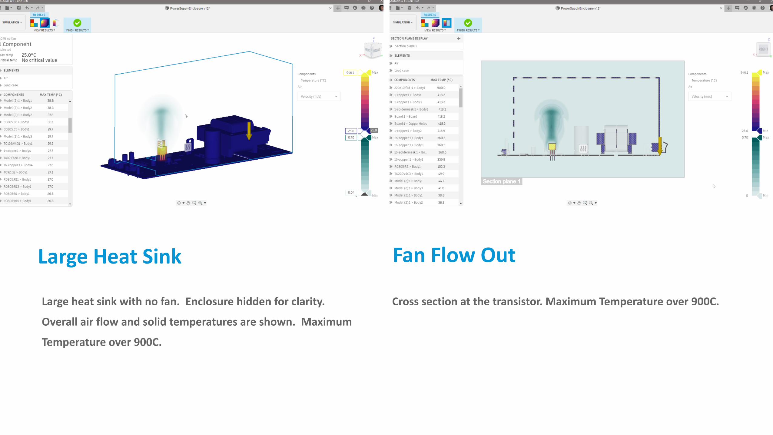
Large Heat Sink
Large heat sink with no fan. Enclosure hidden for clarity.
Overall air flow and solid temperatures are shown. Maximum
Temperature over 900C.
Cross section at the transistor. Maximum Temperature over 900C.
Fan Flow Out

Large Heat Sink Added
The transistor is now attached to a large heat sink
• Natural convection
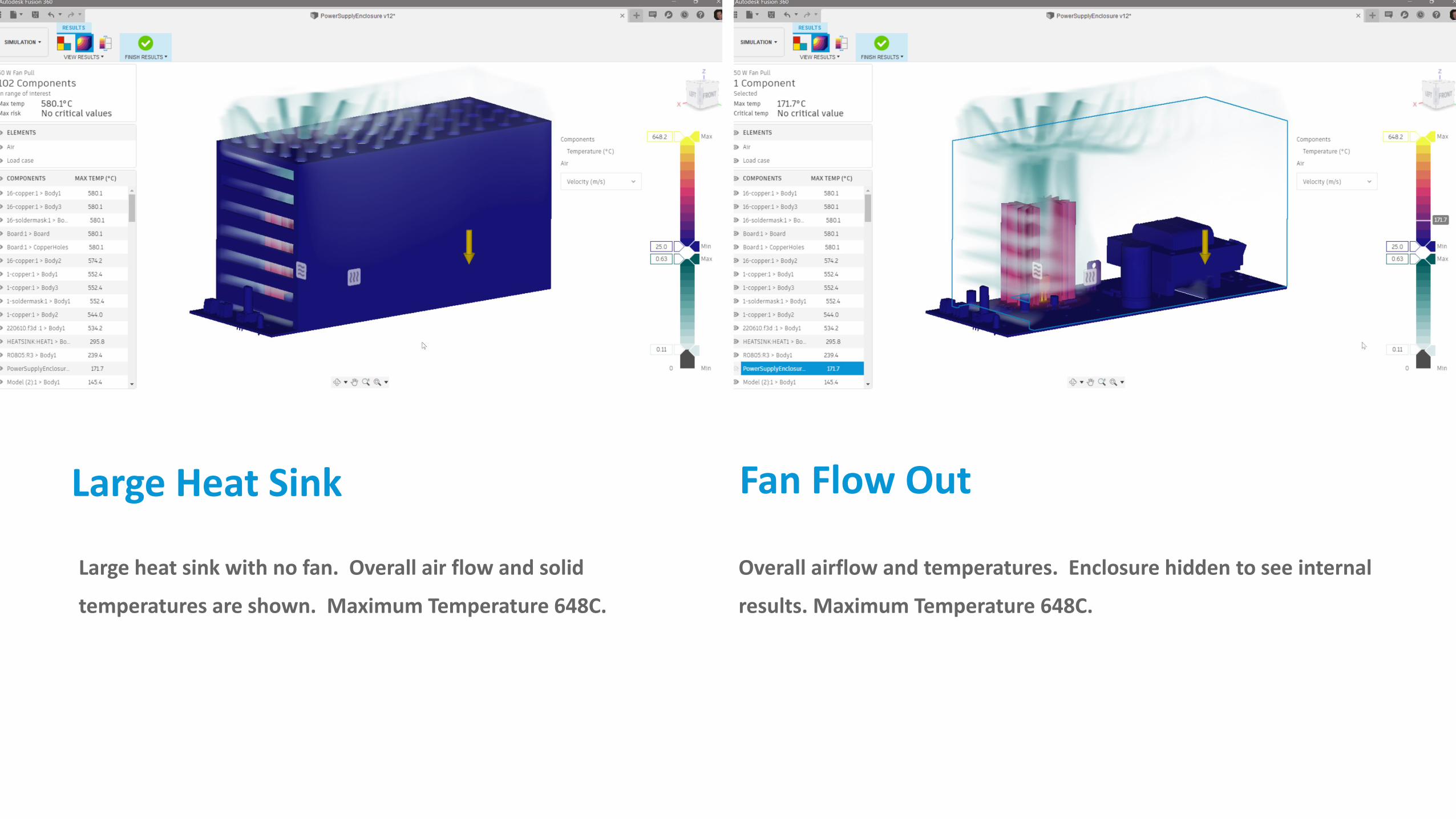
Large Heat Sink
Large heat sink with no fan. Overall air flow and solid
temperatures are shown. Maximum Temperature 648C.
Overall airflow and temperatures. Enclosure hidden to see internal
results. Maximum Temperature 648C.
Fan Flow Out

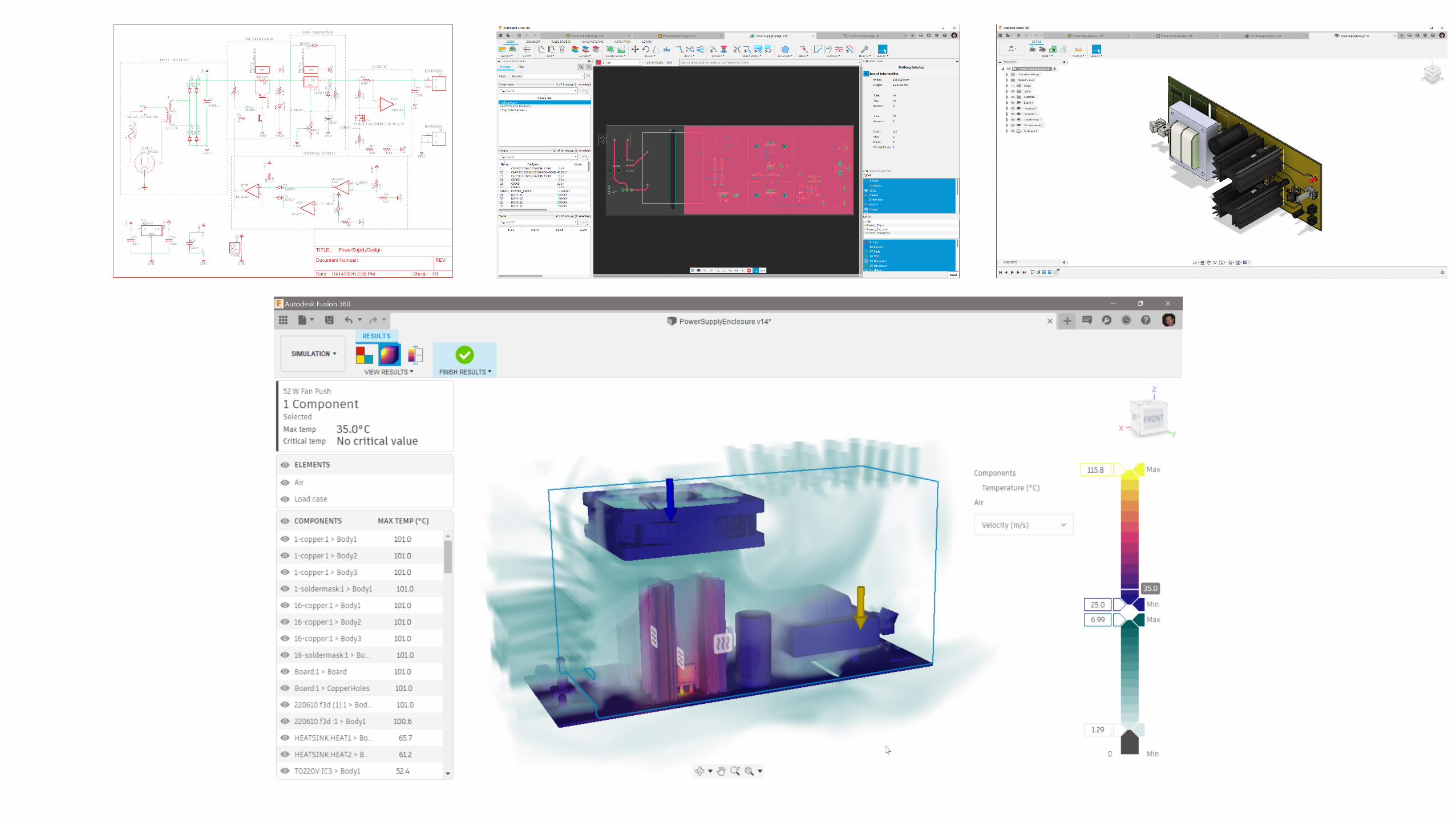
Heat Load Divided
The heat load is divided over our regulator and power resistor
each attached to their own heat sink
• 41 cfm fan also added
o 1st we try flow pulled out of the enclosure
o 2nd we try flow pulled into the enclosure

Fan Flow Out
Fan flow rate into enclosure. Overall air flow and solid
temperatures are shown. Maximum Temperature 345C.
Cross section of air flow. Maximum Temperature 345C.
Fan Flow Out

Fan Flow In
Fan flow rate into enclosure. Overall air flow and solid
temperatures are shown. Maximum Temperature 115C.
Cross section of air flow. Maximum Temperature 115C.
Fan Flow In

Demonstration
Watch the demo video here:https://drive.autodesk.com/new/de29810b9/shares/SH56a43QTfd62c1cd96828c30d78f9374618
Or watch it in context in our class at AU2020

Wrap-up

Autodesk and the Autodesk logo are registered trademarks or trademarks of Autodesk, Inc., and/or its subsidiaries and/or affiliates in the USA and/or other countries. All other brand names, product names, or trademarks belong to their respective holders. Autodesk reserves the right to alter product and services offerings, and specifications and pricing at any time without notice, and is not responsible for typographical or graphical errors that may appear in this document.
© 2020 Autodesk. All rights reserved.