futera iii series finned copper gas boilers (model mb) &...
TRANSCRIPT
FUTERA III SERIES FINNED COPPERGAS BOILERS (MODEL MB)
& WATER HEATERS (MODEL MW)INSTALLATION & OPERATION MANUAL
INSTALLER, THESE INSTRUCTIONS TO BE AFFIXED ADJACENT TO THE BOILER / WATER HEATER.CONSUMER, RETAIN THESE INSTRUCTIONS FOR FUTURE REFERENCE PURPOSES.
DESIGNED AND TESTED ACCORDING TO A.S.M.E. BOILER AND PRESSUREVESSEL CODE, SECTION IV FOR A MAXIMUM ALLOWABLE WORKING PRESSUREOF 160 PSI, 1103 kPa WATER.
FTIII-IOM-1
260 North Elm Street 1300 Midway BoulevardWestfield, MA 01085
�Mississauga, Ontario L5T 2G8 Canada
Phone: (413) 568-9571 Phone: (905) 670-5888Fax: (413) 568-9613 Fax: (905) 670-5782
www.rbiwaterheaters.com
WARNING: If the information in this manual is not followed exactly, a fireor explosion may result causing property damage, personal injury or loss of life.
Do not store or use gasoline or other flammable vapors and liquids in the vicinity ofthis or any other appliance.
WHAT TO DO IF YOU SMELL GAS:• Do not try to light any appliance.• Do not touch any electrical switch. Do not use any phone in your building.• Immediately call your gas supplier from a neighbor’s phone. Follow the gas
supplier’s instructions.• If you cannot reach your gas supplier, call the fire department.Installation and service must be performed by a qualified installer, service agency orthe gas supplier.
WARNING: Failure to properly vent this unit can cause excessive amounts of carbonmonoxide resulting in severe personnal injury or death!
2
FUTERA III INSTALLATION AND OPERATION INSTRUCTIONS
CONTENTS
Before Your Start page 2
Ratings & Capacities page 3
Boiler/Water Heater Location page 3
Combustion Air & Ventilation page 3
General Venting Guidelines page 5
Common Vent Systems page 11
General Piping Requirements page 12
Heating System Piping page 13
Domestic Water Supply Piping page 17
Gas Supply Piping page 21
Electrical Wiring page 22
General Operation page 22
Operating Instructions page 23
Checking & Adjustments page 25
Control Description page 26
MPA Staging Control page 26
Diagnostics page 27
Maintenance page 28
Trouble-Shooting page 30
Repair Parts page 31
Startup Sheet page 37
BEFORE YOU STARTThis manual covers the application, installation, operationand maintenance of a Futera III Series finned copperheating boiler/water heater.
To obtain the safe, dependable, efficient operation and longlife for which this heating boiler/water heater was designed,these instructions must be read, understood and followed.
AVERTISSMENT. Assurez-vous de bien suivre les instructions données dans cette notice pourréduire au minimum le risque d’incendie ou d’explosion ou pour éviter tout dommoge matériel,toute blessure ou la mort
Ne pas entreposer ni utiliser d’essence ou ni d’autres vapeurs ou liquides inflammables àproximité de cet appareil ou de tout autre appareil.
QUE FAIRE SI VOUS SENTEZ UNE ODEUR DE GAZ:
• Ne pas tenter d’allumer d’appareil.• Ne touchez à aucun interrupteur; ne pas vous servir des téléphones se trouvant dans le bâtiment.• Appelez immédiatement votre fournisseur de gas depuis un voisin. Suivez les intructions du fournisseur.• Si vous ne purvez rejoindre le fournisseur, appelez le service des incendies.
L’installation et l’entretien doivent être assurés par un installateur ou un service d’entretienqualifié ou par le fournisseur de gaz.
The Futera III Series finned copper heating boiler/waterheaters have been design certified by CSA for use withnatural and propane gas under the latest revision of ANSI-Z21.10.3/CSA 4.3, Gas Water Heaters, ANSI-Z21.13/CSA4.9, Gas-Fired Low Pressure Steam and Hot Water Boilersand CAN1-3.1, Industrial and Commercial Gas FiredPackaged Boilers. Each unit has been constructed andhydrostatically tested for a maximum working pressure of160 psi, 1103 kPa in accordance with Section IV of theA.S.M.E. Boiler and Pressure Vessel Code.
All aspects of the boiler/water heater installation mustconform to the requirements of the authority having juris-diction, or, in the absence of such requirements, to theNational Fuel Gas Code, ANSI Z223.1/NFPA 54-latestrevision. Where required by the authority having jurisdiction,the installation must conform to the Standard for Controlsand Safety Devices for Automatically Fired Boilers, ANSI/ASME CSD-1.
In Canada, the installation must be in accordance with therequirements of CSA B149.1 or .2, Installation Code forGas Burning Appliances and Equipment.
If installed in the Commonwealth of Massachusetts, youMUST FOLLOW the additional instructions contained inRBI’s instruction sheet MA IOM. If you don’t have a copycall your RBI representative.
The owner should maintain a record of all service workperformed with the date and a description of the work done.Include the name of the service organization for futurereference.
Direct all questions to your RBI distributor or contact theRBI Customer Service Department at: 260 North ElmStreet, Westfield, MA 01085 for US or 1300 MidwayBoulevard, Mississauga ONT L5T 2G8 for Canada. Alwaysinclude the model and serial numbers from the rating plateof the boiler/water heater in question.
3
FUTERA III INSTALLATION AND OPERATION INSTRUCTIONS
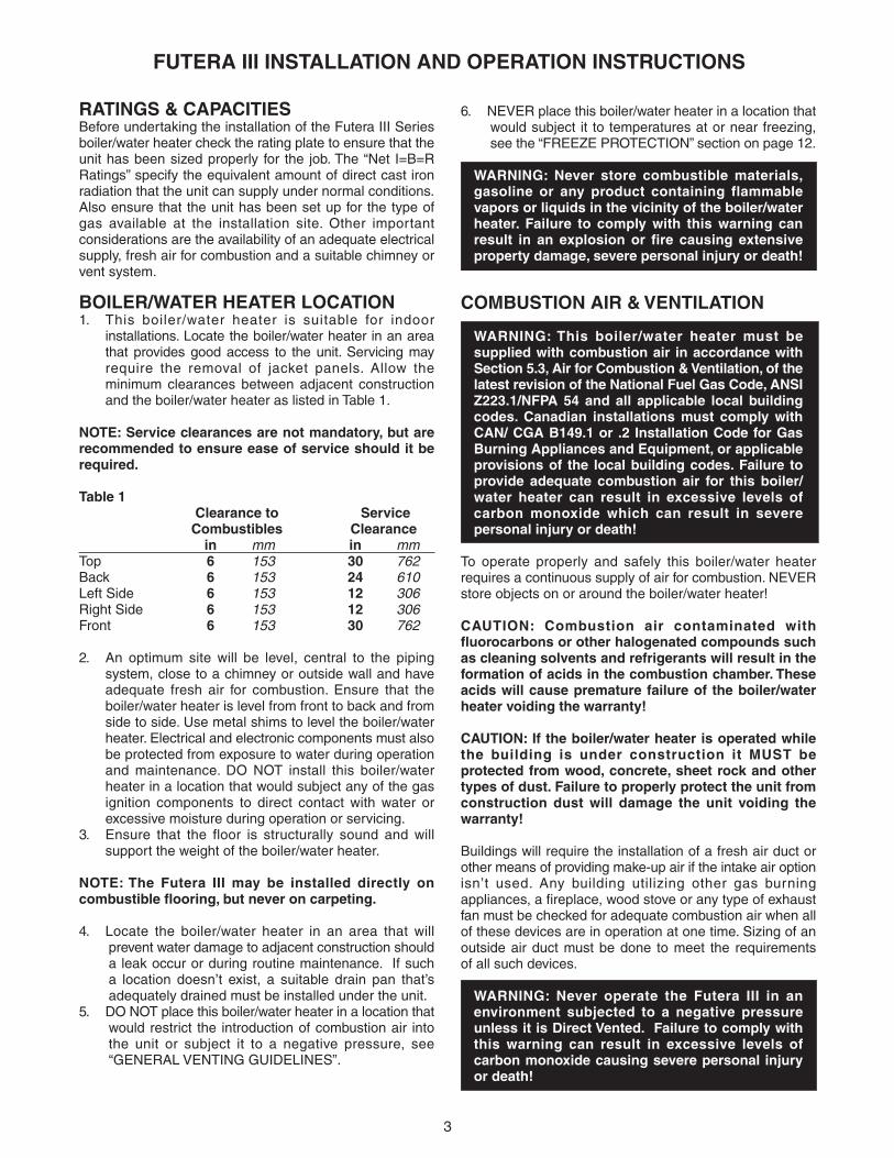
RATINGS & CAPACITIESBefore undertaking the installation of the Futera III Seriesboiler/water heater check the rating plate to ensure that theunit has been sized properly for the job. The “Net I=B=RRatings” specify the equivalent amount of direct cast ironradiation that the unit can supply under normal conditions.Also ensure that the unit has been set up for the type ofgas available at the installation site. Other importantconsiderations are the availability of an adequate electricalsupply, fresh air for combustion and a suitable chimney orvent system.
BOILER/WATER HEATER LOCATION1. This boiler/water heater is suitable for indoor
installations. Locate the boiler/water heater in an areathat provides good access to the unit. Servicing mayrequire the removal of jacket panels. Allow theminimum clearances between adjacent constructionand the boiler/water heater as listed in Table 1.
NOTE: Service clearances are not mandatory, but arerecommended to ensure ease of service should it berequired.
Table 1Clearance to Service
Combustibles Clearancein mm in mm
Top 6 153 30 762Back 6 153 24 610Left Side 6 153 12 306Right Side 6 153 12 306Front 6 153 30 762
2. An optimum site will be level, central to the pipingsystem, close to a chimney or outside wall and haveadequate fresh air for combustion. Ensure that theboiler/water heater is level from front to back and fromside to side. Use metal shims to level the boiler/waterheater. Electrical and electronic components must alsobe protected from exposure to water during operationand maintenance. DO NOT install this boiler/waterheater in a location that would subject any of the gasignition components to direct contact with water orexcessive moisture during operation or servicing.
3. Ensure that the floor is structurally sound and willsupport the weight of the boiler/water heater.
NOTE: The Futera III may be installed directly oncombustible flooring, but never on carpeting.
4. Locate the boiler/water heater in an area that willprevent water damage to adjacent construction shoulda leak occur or during routine maintenance. If sucha location doesn’t exist, a suitable drain pan that’sadequately drained must be installed under the unit.
5. DO NOT place this boiler/water heater in a location thatwould restrict the introduction of combustion air intothe unit or subject it to a negative pressure, see“GENERAL VENTING GUIDELINES”.
6. NEVER place this boiler/water heater in a location thatwould subject it to temperatures at or near freezing,see the “FREEZE PROTECTION” section on page 12.
WARNING: Never store combustible materials,gasoline or any product containing flammablevapors or liquids in the vicinity of the boiler/waterheater. Failure to comply with this warning canresult in an explosion or fire causing extensiveproperty damage, severe personal injury or death!
COMBUSTION AIR & VENTILATION
WARNING: This boiler/water heater must besupplied with combustion air in accordance withSection 5.3, Air for Combustion & Ventilation, of thelatest revision of the National Fuel Gas Code, ANSIZ223.1/NFPA 54 and all applicable local buildingcodes. Canadian installations must comply withCAN/ CGA B149.1 or .2 Installation Code for GasBurning Appliances and Equipment, or applicableprovisions of the local building codes. Failure toprovide adequate combustion air for this boiler/water heater can result in excessive levels ofcarbon monoxide which can result in severepersonal injury or death!
To operate properly and safely this boiler/water heaterrequires a continuous supply of air for combustion. NEVERstore objects on or around the boiler/water heater!
CAUTION: Combustion air contaminated withfluorocarbons or other halogenated compounds suchas cleaning solvents and refrigerants will result in theformation of acids in the combustion chamber. Theseacids will cause premature failure of the boiler/waterheater voiding the warranty!
CAUTION: If the boiler/water heater is operated whilethe building is under construction it MUST beprotected from wood, concrete, sheet rock and othertypes of dust. Failure to properly protect the unit fromconstruction dust will damage the unit voiding thewarranty!
Buildings will require the installation of a fresh air duct orother means of providing make-up air if the intake air optionisn’t used. Any building utilizing other gas burningappliances, a fireplace, wood stove or any type of exhaustfan must be checked for adequate combustion air when allof these devices are in operation at one time. Sizing of anoutside air duct must be done to meet the requirementsof all such devices.
WARNING: Never operate the Futera III in anenvironment subjected to a negative pressureunless it is Direct Vented. Failure to comply withthis warning can result in excessive levels ofcarbon monoxide causing severe personal injuryor death!

4
FUTERA III INSTALLATION AND OPERATION INSTRUCTIONS
All Air From Inside The BuildingIf the Futera III is to be located in a confined space,the minimum clearances listed in Table 1 must bemaintained between it and any combustible construction.When installed in a confined space without the intakeair option, Figures 5, 6 and 7, two permanent openingscommunicating with an additional room(s) are required.The combined volume of these spaces must havesufficient volume to meet the criteria for an unconfinedspace. The total air requirements of all gas utilizationequipment, fireplaces, wood stoves or any type ofexhaust fan must be considered when making thisdetermination. Each opening must have a minimum freearea of 1 in2/1000 Btu/hr, 2200 mm2/kW based on thetotal input rating of ALL gas utilization equipment in theconfined area. Each opening must be no less than100 in2, 64,516 mm2 in size. The upper opening mustbe within 12 in, 305 mm of, but not less than 3 in,76 mm from, the top of the enclosure. The bottomopening must be within 12 in, 305 mm of, but not lessthan 3 in, 76 mm from, the bottom of the enclosure.
All Air From Outside The BuildingWhen installed in a confined space without utilizing theintake air option two permanent openings communicatingdirectly with, or by ducts to, the outdoors or spaces thatfreely communicate with the outdoors must be present. Theupper opening must be within 12 in, 305 mm of, but notless than 3 in, 76 mm from, the top of the enclosure. Thebottom opening must be within 12 in, 305 mm of, but notless than 3 in, 76 mm from, the bottom of the enclosure.
Where directly communicating with the outdoorsor communicating with the outdoors through verticalducts, each opening shall have a minimum free area of1 in2/4000 Btu/hr, 550 mm2/kW of the total input ratingof all of the equipment in the enclosure.
Where communicating with the outdoors through horizontalducts, each opening shall have a minimum free area of1 in2/2000 Btu/hr, 1100 mm2/kW of the total input ratingof all of the equipment in the enclosure.
When ducts are used, they must have the same cross-sectional area as the free area of the opening to which theyconnect.
When calculating the free area necessary to meet themake-up air requirements of the enclosure, considerationmust be given to the blockage effects of louvers, grills andscreens. Screens must have a minimum mesh size of1/4 in, 6.4 mm. If the free area through a louver or grill isnot known, ducts should be sized per Table 2.
Table 2 – Make-up Air Louver SizingRequired Cross Sectional Area
Input 1/4 in 6.4 mm 75% Free Area 25% Free Area(MBH) Wire Screen Metal Louvers Wooden Louvers
in2 cm2 in2 cm2 in2 cm2
500 125 806 167 1077 500 3226 750 187 1206 250 1613 750 48391000 250 1613 333 2148 1000 64521250 313 2019 416 2684 1250 80651500 375 2419 500 3226 1500 96771750 437 2819 583 3761 1750 11,2901999 500 3226 667 4303 2000 12,900
Canadian installations must comply with CSA B149.1 whenair supply is provided by natural air flow from the outdoorsfor natural draft, partial fan-assisted, fan-assisted, orpower draft-assisted burners, there shall be a permanentair supply opening(s) having a cross-sectional area of notless than 1 in2 per 7,000 Btuh (310 mm2 per kW) up toand including 1 million Btuh, plus 1 in2 per 14,000 Btuh(155 mm2 per kW) in excess of 1 million Btuh.
Intake Air Option – General GuidelinesThis configuration provides combustion air directly to theboiler/water heater’s air intake using a dedicated pipe whenusing the direct vent option. The RBI air intake adaptermust be fitted to the blower inlet. Combustion air can bedrawn in horizontally through the same outside wall whichterminates the exhaust gases or vertically through the roof,see Figures 1, 2, 3 & 4.
WARNING: Common intake air systems may beused provided the common duct is sized properlyand an intake combustion air damper is installedin the intake air pipe of each heater. Improperinstallation can result in excessive levels of carbonmonoxide which can cause severe personal injuryor death!
Single wall galvanized smoke pipe, single wall aluminumpipe, flexible aluminum pipe, PVC or CPVC pipe can beused for the intake air pipe. It must be sized per Table 3.
Table 3 - Intake Air Pipe SizingModel For Vertical For HorizontalSize (Up to 60') (Up To 60')
in mm in mm 500 8 203 6 152 750 8 203 6 1521000 8 203 6 1521250 10 254 8 2031500 10 254 10 2541750 12 305 12 3052000 12 305 12 305
All joints in metal intake air systems must be secured usingcorrosion resistant fasteners and sealed using a suitableSilicone caulk. If PVC or CPVC is used, the joints must becleaned with a suitable solvent and connected using asolvent based PVC cement. The combustion air systemMUST be supported by the building structure not theboiler/water heater.
5
FUTERA III INSTALLATION AND OPERATION INSTRUCTIONS
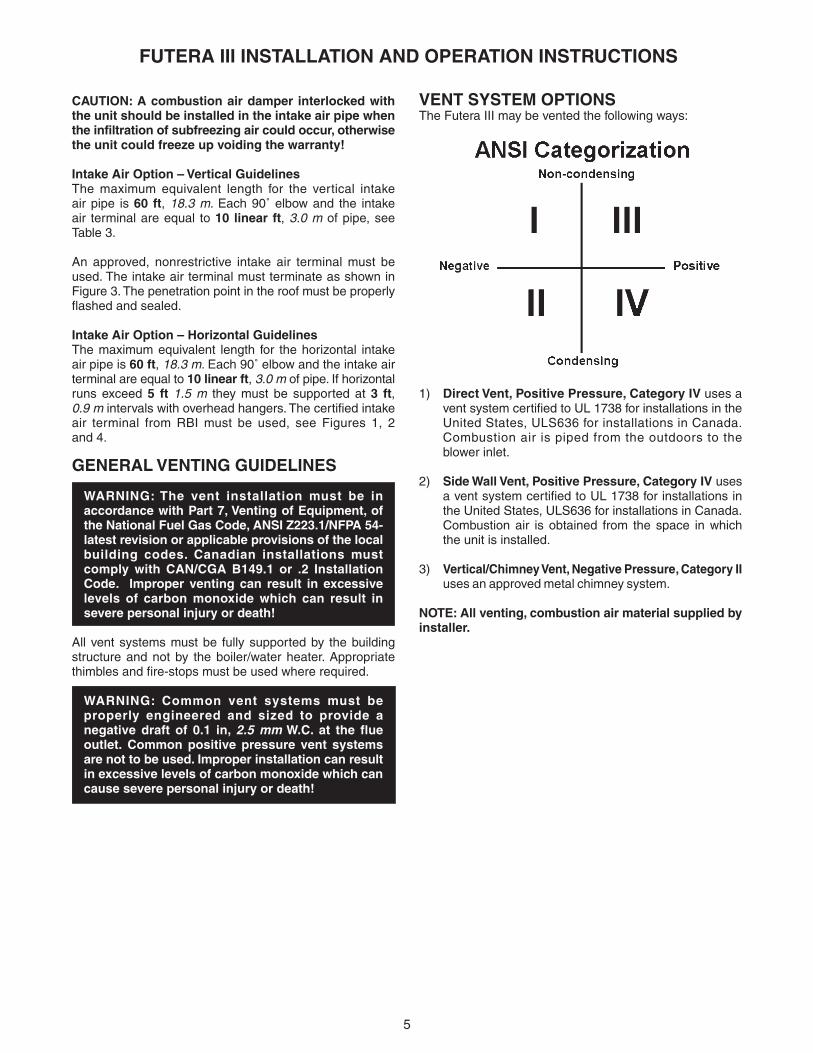
VENT SYSTEM OPTIONSThe Futera III may be vented the following ways:
1) Direct Vent, Positive Pressure, Category IV uses avent system certified to UL 1738 for installations in theUnited States, ULS636 for installations in Canada.Combustion air is piped from the outdoors to theblower inlet.
2) Side Wall Vent, Positive Pressure, Category IV usesa vent system certified to UL 1738 for installations inthe United States, ULS636 for installations in Canada.Combustion air is obtained from the space in whichthe unit is installed.
3) Vertical/Chimney Vent, Negative Pressure, Category IIuses an approved metal chimney system.
NOTE: All venting, combustion air material supplied byinstaller.
CAUTION: A combustion air damper interlocked withthe unit should be installed in the intake air pipe whenthe infiltration of subfreezing air could occur, otherwisethe unit could freeze up voiding the warranty!
Intake Air Option – Vertical GuidelinesThe maximum equivalent length for the vertical intakeair pipe is 60 ft, 18.3 m. Each 90˚ elbow and the intakeair terminal are equal to 10 linear ft, 3.0 m of pipe, seeTable 3.
An approved, nonrestrictive intake air terminal must beused. The intake air terminal must terminate as shown inFigure 3. The penetration point in the roof must be properlyflashed and sealed.
Intake Air Option – Horizontal GuidelinesThe maximum equivalent length for the horizontal intakeair pipe is 60 ft, 18.3 m. Each 90˚ elbow and the intake airterminal are equal to 10 linear ft, 3.0 m of pipe. If horizontalruns exceed 5 ft 1.5 m they must be supported at 3 ft,0.9 m intervals with overhead hangers. The certified intakeair terminal from RBI must be used, see Figures 1, 2and 4.
GENERAL VENTING GUIDELINES
WARNING: The vent installation must be inaccordance with Part 7, Venting of Equipment, ofthe National Fuel Gas Code, ANSI Z223.1/NFPA 54-latest revision or applicable provisions of the localbuilding codes. Canadian installations mustcomply with CAN/CGA B149.1 or .2 InstallationCode. Improper venting can result in excessivelevels of carbon monoxide which can result insevere personal injury or death!
All vent systems must be fully supported by the buildingstructure and not by the boiler/water heater. Appropriatethimbles and fire-stops must be used where required.
WARNING: Common vent systems must beproperly engineered and sized to provide anegative draft of 0.1 in, 2.5 mm W.C. at the flueoutlet. Common positive pressure vent systemsare not to be used. Improper installation can resultin excessive levels of carbon monoxide which cancause severe personal injury or death!

6
FUTERA III INSTALLATION AND OPERATION INSTRUCTIONS
DIRECT VENT,POSITIVE PRESSURE, CATEGORY IVIn this configuration the boiler/water heater blower is usedto push the flue products to the outdoors while drawingcombustion air from the outdoors. The Intake AirOption instructions under the “COMBUSTION AIR &VENTILATION” section must be followed! The vent systemmust be sized per Table 4.
Table 4 – Category IVModel Pipe DiameterSize (Up to 60')
in mm 500 5 127 750 5 1271000 6 1521250 6 1521500 8 2031750 10 2542000 10 254
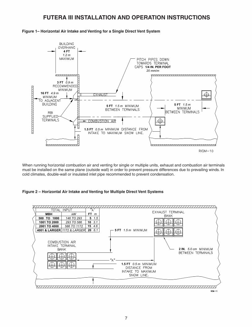
Horizontal Direct Vent Systems – Figures 1 & 2The vent materials used in horizontal vent systems mustbe certified to UL 1738 for installations in the United States,ULS636 for installations in Canada. The certified ventterminal from RBI must also be used.
The maximum equivalent length for the horizontal vent pipeis 60 ft, 18.3 m. Each 90˚ elbow and the vent terminal areequal to 10 linear ft, 3.0 m of pipe. If any part of a singlewall metal vent system passes through an unheated space,it must be insulated with insulation rated for 400° F, 204°C.Structrual penetrations must be made using approved fire-stops. For best results, horizontal vent systems should beas short and straight as possible.
The vent system must be both gas tight and watertight. Allseams and joints in metal pipes must be joined and sealedin accordance with the vent system manufacturer’sinstructions.
When horizontal vent runs exceed 5 ft, 1.5 m they must besupported at 3 ft, 0.9 m intervals with overhead hangers.The vent system must be pitched down, toward the ventterminal, 1/4 in/ft, 20 mm/m. If any part of a single wall metalvent system passes through an unheated space it must beinsulated with insulation rated for 400˚F, 204°C.
Horizontal vent systems shall terminate at least 4 ft,1.2 m below, 4 ft, 1.2 m horizontally from or 1 ft,0.30 m above any door, window or gravity air inlet intoany building. It must not terminate less than 4 ft, 1.2 mhorizontally from, and in no case above or below, unlessa 4 ft, 1.2 m horizontal distance is maintained, from electricmeters, gas meters, regulators and relief equipment andnot less than 7 ft, 2.1 m from any adjacent public walkway.The bottom of the vent terminal(s) shall be located atleast 5 ft, 1.5 m above the air intake terminal(s) unlessthere is a minimum 5 ft, 1.5 m horizontal separationbetween them. Avoid terminal locations likely to be affectedby winds, snowdrifts, people and pets. Protect buildingmaterials and vegetation from degradation caused by theflue gases.
Vertical Direct Vent Systems – Figure 3If any part of a single wall metal vent system passesthrough an unheated space, it must be insulated withinsulation rated for 400˚F, 204°C. Structural penetrationsmust be made using approved fire-stops.
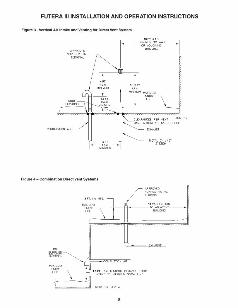
An approved, nonrestrictive vent terminal must be used.The top of a vertical vent system must extend at least51/2 ft, 1.7 m above the roof surface and maximum snowline that it passes through, 4 ft, 1.2 m above the intake airterminal, see Figure 3.
In addition the vent system must conform to the dimensionsshown in Figure 3. The penetration point in the roof mustbe properly flashed and sealed.
The vent system must be gas tight. All seams and jointsin metal pipes must be joined and sealed in accordancewith the vent system manufacturer’s instructions.
Combination Direct Vent Systems – Figure 4The boiler/water heater can be vented vertically with theintake air piped horizontally through an outside wall. Followthe instructions in the Intake Air Option – HorizontalGuidelines on page 5. Also follow the general instructionsin the “COMBUSTION AIR & VENTILATION” and“GENERAL VENTING GUIDELINES” sections.
7
FUTERA III INSTALLATION AND OPERATION INSTRUCTIONS
Figure 1– Horizontal Air Intake and Venting for a Single Direct Vent System
Figure 2 – Horizontal Air Intake and Venting for Multiple Direct Vent Systems
When running horizontal combustion air and venting for single or multiple units, exhaust and combustion air terminalsmust be installed on the same plane (outside wall) in order to prevent pressure differences due to prevailing winds. Incold climates, double-wall or insulated inlet pipe recommended to prevent condensation.
5 FT 1.5 m
3 FT 0.9 m
16 FT 4.9 m
4 FT1.2 m
5 FT 1.5 m
1/4 IN. PER FOOT20 mm/m
1.5 FT 0.5 m
5 FT 1.5 m
1.5 FT 0.5 m
2 IN. 5.0 cm
4001 & LARGER2001 TO 40001001 TO 2000500 TO 1000
MBH FT m
15 4.620 6.1
5 1.510 3.1
kW146 TO 293293 TO 586586 TO 1172
1172 & LARGER
8
FUTERA III INSTALLATION AND OPERATION INSTRUCTIONS
Figure 3 - Vertical Air Intake and Venting for Direct Vent System
Figure 4 – Combination Direct Vent Systems
10 FT 3.1 m
4 FT1.2 m
5 FT1.5 m
1.5 FT0.5 m
5 1/2 FT1.7 m
1.5 FT. .5 m
10 FT. 3.1 m
3 FT. 1 m

9
FUTERA III INSTALLATION AND OPERATION INSTRUCTIONS
WARNING: If an appliance using any type of amechanical draft system operating under positivepressure is connected to a chimney flue, neverconnect any other appliances to this flue. Doingso can result in excessive levels of carbonmonoxide which can cause severe personal injuryor death!
Chimney Inspection & SizingA thorough inspection of the masonry chimney must beperformed to ensure that the chimney is clean, properlyconstructed, lined and sized. Exterior masonry chimneysshould not be used unless properly lined to preventcondensation and draft problems. Table 5 lists theequivalent breeching and flue sizes required for the boiler/water heater.
Table 5 - Equivalent Breeching & Chimney Size,Negative Pressure
Model Size Pipe Diameterin mm
500 6 152 750 6 1521000 7 1781250 8 2031500 8 2031750 10 2542000 10 254
Note: These sizes are based on a 20 ft, 6.1m chimney height.
Figure 5 – Side Wall Venting
SIDE WALL VENT,POSITIVE PRESSURE, CATEGORY IVIn this configuration the boiler/water heater blower is usedto push the flue products horizontally to the outdoors, seeFigure 5. The air for combustion is taken from the spacein which the unit is installed. The applicable instructionsunder the “COMBUSTION AIR & VENTILATION” sectionmust be followed! The vent guidelines under the HorizontalDirect Vent Systems section must also be followed.
VERTICAL/CHIMNEY VENT,NEGATIVE PRESSURE, CATEGORY IIThe Futera III is listed as a Category II appliance whenvented vertically into a listed metal chimney system,Figures 6 & 7. The chimney must provide a negativepressure not greater than 0.15 in, 3.8 mm W.C. at theboiler/water heater flue collar with the unit running. Abarometric damper must be installed between the fluecollar and the vent connector when negative pressuresexceed 0.15 in, 3.8 mm W.C.
NOTE: When using a listed metal chimney system thechimney system manufacturer’s instructions must befollowed.
When more than one appliance is connected to the samechimney flue, the flue must be large enough to safely ventthe combined output of all of the appliances.
1.5 FT 0.5 m
1/4 IN. PER F00T 20 mm/m
4 FT1.2 m
3 FT0.9 m
24"0.6 m

10
FUTERA III INSTALLATION AND OPERATION INSTRUCTIONS
Figure 6 – Vertical Venting with a Metal Chimney System
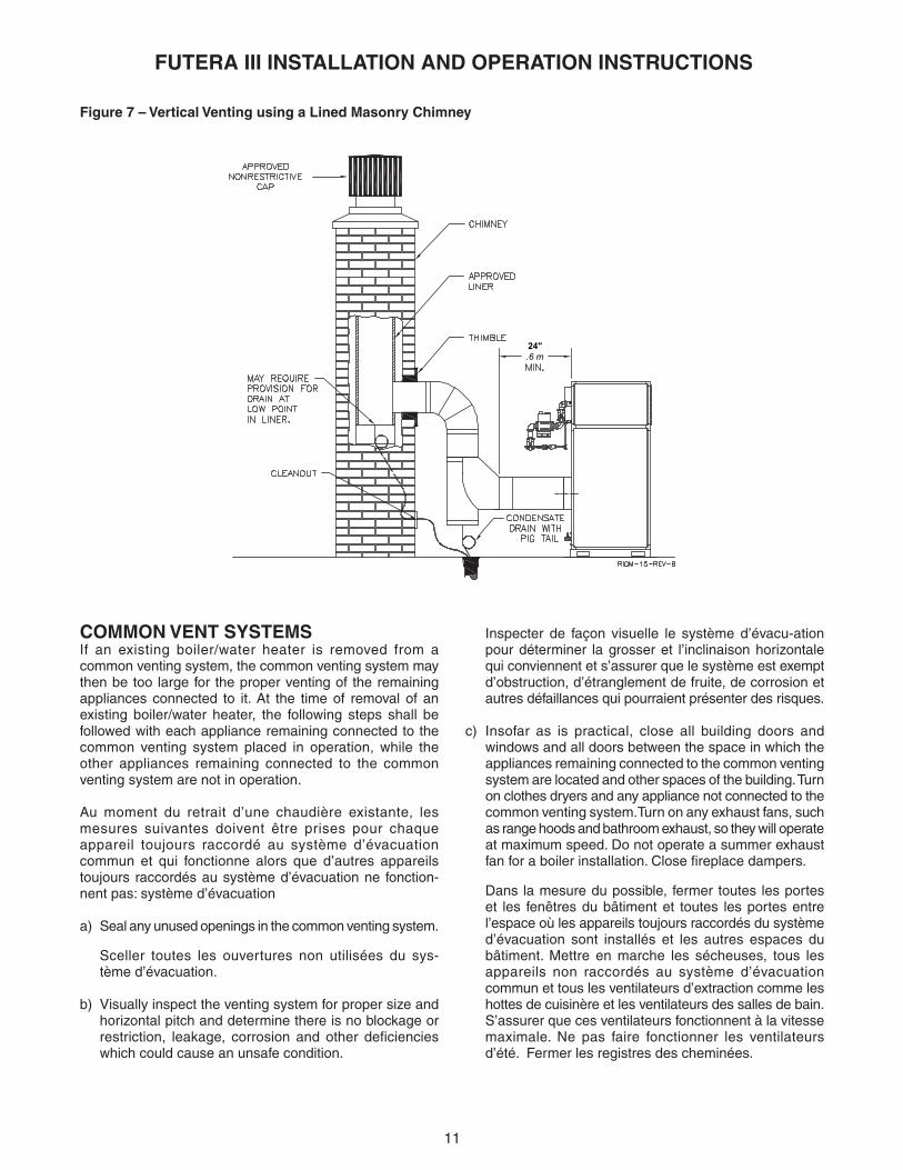
Vent ConnectionsLocate the boiler/water heater as close to the chimney aspossible. Use the shortest, straightest vent connectorpossible for the installation. If horizontal runs exceed 5 ft,1.5 m they must be supported at 3 ft, 0.9 m intervals withoverhead hangers. Use a single wall stainless steel ventpipe the same diameter as the flue collar to connect theboiler/water heater to a masonry chimney. When using alisted metal chimney system use the appropriate ventconnector.
The vent connector should be sloped up toward thechimney at a minimum rate of 1/4 in/ft, 21 mm/m. Onmasonry chimneys the connector must terminate flush withthe inside of the chimney flue, Figure 7. Fasten each singlewall vent connection with at least 3 corrosion resistantsheet metal screws.
Always provide a minimum clearance of 6 in, 152 mmbetween single wall vent pipe and any combustiblematerials.
WARNING: Failure to maintain minimumclearances between vent connectors and anycombustible material can result in a fire causingextensive property damage, severe personal injuryor death!
10 FT. 3.1 m
24".6 m
11
FUTERA III INSTALLATION AND OPERATION INSTRUCTIONS
Figure 7 – Vertical Venting using a Lined Masonry Chimney
Inspecter de façon visuelle le système d’évacu-ationpour déterminer la grosser et l’inclinaison horizontalequi conviennent et s’assurer que le système est exemptd’obstruction, d’étranglement de fruite, de corrosion etautres défaillances qui pourraient présenter des risques.
c) Insofar as is practical, close all building doors andwindows and all doors between the space in which theappliances remaining connected to the common ventingsystem are located and other spaces of the building. Turnon clothes dryers and any appliance not connected to thecommon venting system.Turn on any exhaust fans, suchas range hoods and bathroom exhaust, so they will operateat maximum speed. Do not operate a summer exhaustfan for a boiler installation. Close fireplace dampers.
Dans la mesure du possible, fermer toutes les porteset les fenêtres du bâtiment et toutes les portes entrel’espace où les appareils toujours raccordés du systèmed’évacuation sont installés et les autres espaces dubâtiment. Mettre en marche les sécheuses, tous lesappareils non raccordés au système d’évacuationcommun et tous les ventilateurs d’extraction comme leshottes de cuisinère et les ventilateurs des salles de bain.S’assurer que ces ventilateurs fonctionnent à la vitessemaximale. Ne pas faire fonctionner les ventilateursd’été. Fermer les registres des cheminées.
COMMON VENT SYSTEMSIf an existing boiler/water heater is removed from acommon venting system, the common venting system maythen be too large for the proper venting of the remainingappliances connected to it. At the time of removal of anexisting boiler/water heater, the following steps shall befollowed with each appliance remaining connected to thecommon venting system placed in operation, while theother appliances remaining connected to the commonventing system are not in operation.
Au moment du retrait d’une chaudière existante, lesmesures suivantes doivent être prises pour chaqueappareil toujours raccordé au système d’évacuationcommun et qui fonctionne alors que d’autres appareilstoujours raccordés au système d’évacuation ne fonction-nent pas: système d’évacuation
a) Seal any unused openings in the common venting system.
Sceller toutes les ouvertures non utilisées du sys-tème d’évacuation.
b) Visually inspect the venting system for proper size andhorizontal pitch and determine there is no blockage orrestriction, leakage, corrosion and other deficiencieswhich could cause an unsafe condition.
24".6 m
12
FUTERA III INSTALLATION AND OPERATION INSTRUCTIONS
d) Place in operation the appliance being inspected. Followthe lighting instructions. Adjust thermostat so appliancewill operate continuously.
Mettre l’appareil inspecté en marche. Suivre lesinstructions d’allumage. Régler le thermostat de façonque l’appareil fonctionne de façon continue.
e) Test for spillage at the draft hood relief opening after 5minutes of main burner operation. Use the flame of amatch or candle, or smoke from a cigarette, cigar orpipe.
Faire fonctionner le brûleur principal pendant 5 minensuite, déterminer si le coupe-tirage déborde àl’ouverture de décharge. Utiliser la flamme d’uneallunette ou d’une chandelle ou la fumée d’unecigarette, d’un cigare ou d’une pipe.
f) After it has been determined that each applianceremaining connected to the common venting systemproperly vents when tested as outlined above, returndoors, windows, exhaust fans, fireplace dampers andany other gas-burning appliance to their previouscondition of use.
Une fois qu’il a été d éterminé, selon la métodeindiquée ci-dessus, que chaque appareil raccordé ausystème d’évacuation est mis à l’air libre de façoradéquate. Remettre les portes et les fenêtres, lesventilateurs, les registres de cheminées et les appareilsau gaz à leur position originale.
g) Any improper operation of the common venting systemshould be corrected so the installation conforms withthe National Fuel Gas Code, ANSI Z223.1/NFPA 54.When resizing any portion of the common ventingsystem, the common venting system should be resizedto approach the minimum size as determined using theappropriate tables in Appendix F in the National FuelGas Code, ANSI Z223.1/ NFPA 54 and or CAN/CGAB149 Installation Codes.
Tout mauvais fonctionnement du systéme d’évacu-tioncommun devrait étré corrigé de façor que l’installationsoit conforme au National Fue Gas Code, ANSIZ223.1/NFPA 54 et (ou) aux codes d’installation CAN/CGA-B149. Si la grosseur d’une section du systèmed’ évacuation doit étré modifiée, le système devrait étrémodifié pour respecter les valeurs minimales destableaux pertinents de l’appendice F du National FuelGas Code, ANSI Z223.1/ NFPA 54 et (ou) des codesd’installation CAN/CGA-B149.
GENERAL PIPING REQUIREMENTS
CAUTION: Improper piping of this boiler/water heaterwill void the manufacturer’s warranty and can causeboiler failure resulting in flooding and extensiveproperty damage! Excessive water hardness causingscaling in the copper heat exchanger tubes is NOTcovered under the manufacturer’s warranty, see Table7. Excessive pitting and erosion of the internal surfaceof the copper heat exchanger tubes is NOT coveredunder the manufacturer’s warranty if the result of highwater flow rates, see Table 7. Return watertemperatures below 125˚F, 52°C will result in heatexchanger damage from excessive condensationvoiding the manufacturer’s warranty, see Primary /Secondary Piping, Figure 9.
NOTE: Shut off valves and unions should be installedat the inlet and outlet connections of the boiler/hotwater heater to provide for isolation of the unit shouldservicing be necessary.
Freeze ProtectionInstallations in areas where the danger of freezing existsare not recommended unless proper freeze protection isprovided. The following precautions MUST be observed:1. A continuous flow of water through the unit MUST be
maintained! The pump responsible for flow through theboiler/water heater must run continuously!
2. An ethylene glycol/water mixture suitable for theminimum temperature that the unit will be exposed tomust be used. The pump must be capable of producinga minimum of 15% more flow and overcoming a 20%increase in head loss. Domestic water systems must beisolated from the water heater by the use of a heatexchanger or other approved method.
3. If the unit must be shut off for any reason the electric,gas and water supplies MUST be shut off and the unitand its pump completely drained.
Relief ValvePipe the discharge of the pressure relief valve as shownin Figure 8.
WARNING: Never install any type of valve betweenthe boiler/water heater and the relief valve or anexplosion causing extensive property damage,severe personal injury or death may occur!
Flow SwitchThe flow switch supplied with the boiler/water heater mustbe wired to the terminal strip in the control panel to preventthe boiler from firing unless there’s adequate water flowthrough the unit. The flow switch must be installed in thesupply piping adjacent to the boiler outlet connection.
CAUTION: Failure to properly install the flow switchmay result in damage to the boiler/water heater heatexchanger voiding the warranty!

13
FUTERA III INSTALLATION AND OPERATION INSTRUCTIONS
HEATING SYSTEM PIPING
General Piping RequirementsAll heating system piping must be installed by a qualifiedtechnician in accordance with the latest revision of theANSI/ASME Boiler and Pressure Vessel Code, Section IV,and ANSI/ASME CSD-1, Standard for Controls and SafetyDevices for Automatically Fired Boilers. All applicable localcodes and ordinances must also be followed. A minimumclearance of 1 in, 25 mm must be maintained betweenheating system pipes and all combustible construction. Allheating system piping must be supported by suitablehangers not the boiler. The thermal expansion of thesystem must be considered when supporting the system.A minimum system pressure of 12 psig, 82.7 kPa mustbe maintained.
Heating Boiler Piping ConnectionsThe supply and return connections should be sized to suitthe system, see Table 6.
Table 6 – Supply & Return Pipe Sizing Model Size Supply Size Return Size 500 thru 1000 2" NPT 2" NPT 1250 thru 2000 2 1/2" NPT 2 1/2" NPT
Pump RequirementsThis low mass boiler requires a continuous minimum waterflow for proper operation. The system pump must be sizedto overcome the head loss of the boiler and the heatingsystem in order to achieve the required temperature rise.Table 7 provides the heat exchanger pressure drop andtemperature rise figures. The temperature rise across theboiler must never exceed 35˚F, 19.4˚C. The adjustablepump delay turns the pump on each time the burner firesand runs the pump for 20 to 600 seconds after the call forheat is satisfied.
CAUTION: A temperature rise outside of the rangelisted in Table 7 indicates that the flow rate through theheat exchanger is incorrect which will damage the heatexchanger voiding the warranty! The maximumallowable temperature rise is 35°F, 19.4°C.
The maximum allowable flow rate through a Futera IIIboiler is 97 GPM, 6.1 L/s on 500 through 1000 modelsand 136 GPM, 8.6 L/s for 1250 through 2000 models.The Cupro-Nickel heat exchanger allows for 108 GPM,6.8 L/s on 500 through 1000 models and 151 GPM,9.5 L/s on 1250 through 2000 models.
Figure 8 – Futera III Piping

14
FUTERA III INSTALLATION AND OPERATION INSTRUCTIONS
Table 7 - Temperature Rise Table∆T = 20°F ∆T = 11.1°C
Model Flow Rate Pres. Drop Flow Rate Pres. DropNumber GPM Ft L/s kPa
500 42.5 0.53 2.7 1.5750 63.8 1.57 4.0 4.6
1000 85.0 3.44 5.4 10.11250 106.3 2.11 6.7 6.21500 127.5 3.57 8.0 10.5
∆T = 25°F ∆T = 13.9°CModel Flow Rate Pres. Drop Flow Rate Pres. Drop
Number GPM Ft L/s kPa500 34.0 0.35 2.1 1.0750 51.0 1.04 3.2 3.1
1000 68.0 2.27 4.3 6.71250 85.0 1.40 5.4 4.11500 102.0 2.36 6.4 7.01750 119.0 3.67 7.5 10.82000 136.0 5.39 8.6 15.9
∆T = 30°F ∆T = 16.7°CModel Flow Rate Pres. Drop Flow Rate Pres. Drop
Number GPM Ft L/s kPa750 42.5 0.74 2.7 2.2
1000 56.7 1.62 3.6 4.81250 70.8 1.00 4.5 2.91500 85.0 1.68 5.4 5.01750 99.2 2.62 6.3 7.72000 113.3 3.84 7.2 11.3
∆T = 35°F ∆T = 19.4°CModel Flow Rate Pres. Drop Flow Rate Pres. Drop
Number GPM Ft L/s kPa750 36.4 0.56 2.3 1.6
1000 48.6 1.22 3.1 3.61250 60.7 0.75 3.8 2.21500 72.9 1.27 4.6 3.71750 85.0 1.97 5.4 5.82000 97.1 2.89 6.1 8.5
Low Water CutoffIf a boiler is installed above any radiation elements it mustbe fitted with a low water cutoff device.
Refer to the wiring diagram supplied with the boiler/waterheater for proper wiring connections.
Expansion Tank & Air SeparatorAn expansion tank or other means to control thermalexpansion must be installed in the heating system. Anexpansion tank must be installed close to the boiler on thesuction side of the pump. An air scoop and automatic airvent must also be installed to eliminate air trapped in thesystem.
Primary/Secondary PipingBoilers connected to heating systems using zone valves,zone pumps, or systems that have excessive flow rates orreturn water temperatures less than 125˚F, 52˚C must beisolated from these systems to protect the boiler.
Variable Water FlowsFigure 9 shows a typical primary/secondary piping system.A dedicated pump is used to maintain a constant water flowthrough the boiler. This secondary pump is sized toovercome the head loss of the boiler and secondary pipingsystem while supplying the flow rate required to maintainthe desired temperature rise across the boiler. The primarypump is sized to provide the required flow to the heatingsystem. The secondary piping connections to the primarysystem piping must not be more than 12 in, 305 mm apartto ensure zero pressure drop in the primary system, seeFigure 9.
Low Return Water TemperaturesTo prevent the problems associated with condensation ofthe products of combustion due to low return watertemperatures a primary/secondary piping system with abypass and bypass valve must be installed, see Figure 10.The bypass and bypass valve must be sized the sameas the secondary piping. A balancing valve must also beinstalled in the supply side of the secondary pipingdownstream of the bypass. The balancing valve shouldbe adjusted to divert some of the heated discharge waterinto the return water until the required inlet watertemperature is achieved. The primary and secondarypumps should be sized to provide the required flow througheach system. The secondary piping connections tothe primary system piping must not be more than 12 in,305 mm apart to ensure zero pressure drop in the primarysystem, see Figure 10.
Multiple Boiler SystemsSystems using multiple boilers can also be installed usinga primary/secondary manifold system, Figure 11.
Piping For Use With Cooling UnitsThe boiler, when used in connection with a refrigerationsystem, must be installed so the chilled medium is pipedin parallel with the boiler. Appropriate valves must be usedto prevent the chilled water from entering the boiler.
When a boiler is connected to a heating coil that may beexposed to refrigerated air from an air handling device, thepiping system must be equipped with flow-control valvesor some other automatic means of preventing gravitycirculation of the boiler water during the cooling cycle.

15
FUTERA III INSTALLATION AND OPERATION INSTRUCTIONS
1
1
Figure 9 - Typical Primary/Secondary Piping System(See Notes)
Figure 10 - Low Temperature Piping(See Notes and Adjustment Procedures)
1. Turn heater on and open valves A & B.2. After steady-state operation, if T1 is less than Temp-Min slowly close valve B until T1 climbs to desired operating temperature above Temp-Min.3. If T1 is greater than desired operating temperature, slowly close valve A to adjust to lower desired temperature above Temp-Min.4. Check after system operating temperature has stabilized. Make final adjustments.5. Follow same adjustment procedure for sealed combustion.
Adjustment Procedure To Maintain Inlet Temperature Above Dew Point
T1-Temp-Min=110° For AtmosphericT1-Temp-Min=125° Sealed Combustion
NOTES:
1. Boiler circuit piping must be sized large enough to handle maximum flow through unit.2. Boiler pump sized to boiler design flow requirements.3. All boilers furnished with factory mounted outlet water temperature gauge.4. Boiler pump purging required. Use terminals supplied.
Notice: These drawings show suggested piping configuration and valving. Check with local codes and ordinances for specific requirements.
Operated Valve
Air Vent
Pressure Switch
Aquastat Union
Gas PressureRegulator
Automatic
Thermometer
Flow Switch
PressureRelief Valve
Reducing Valve
Self-Operated
Check Valve
Pressure
Valve
Pump
Motorized Valve
Solenoid
Ball Valve
Bufferfly Valve
Angle Valve
Gate Valve
Globe Valve
Balance Valve
Backflow-Prevention
Device
H-1 Rev 2
H-3 Rev 2
16
FUTERA III INSTALLATION AND OPERATION INSTRUCTIONS
1
5
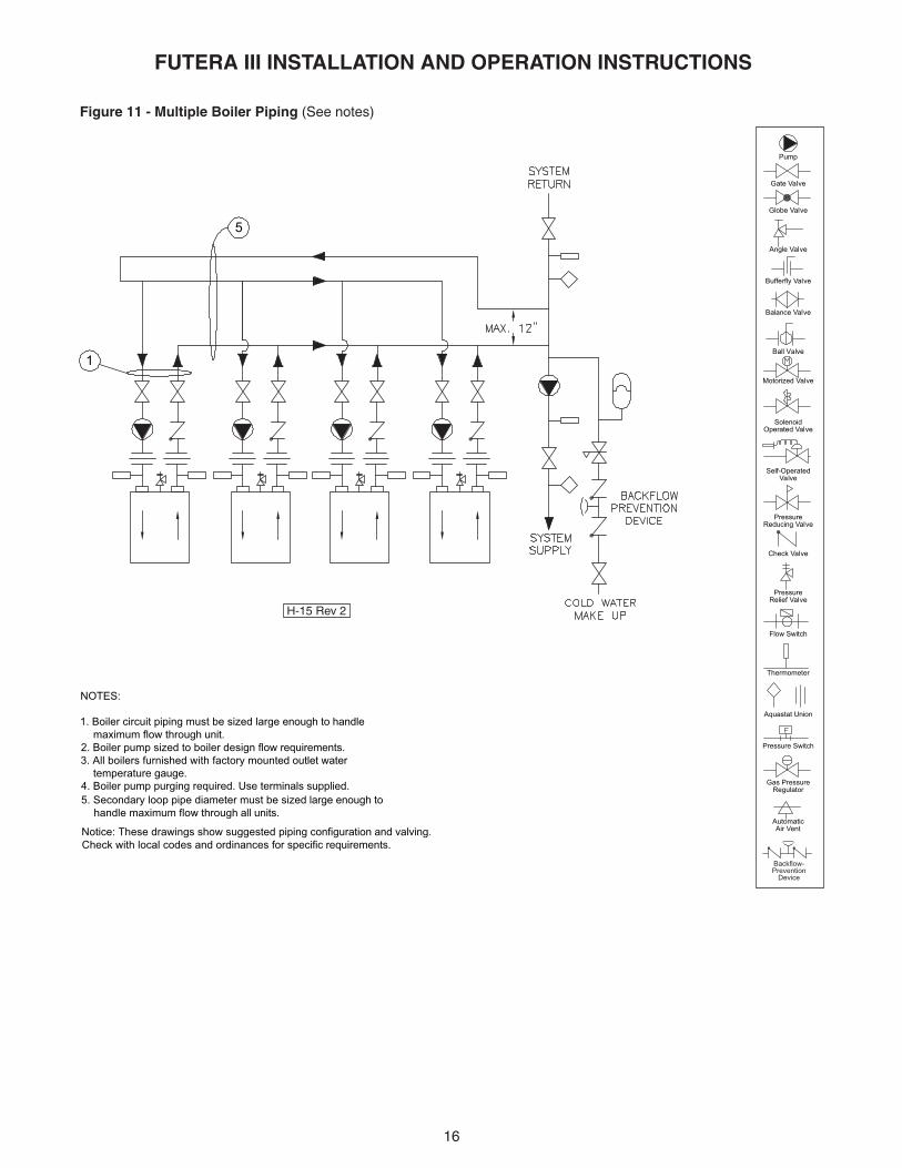
Figure 11 - Multiple Boiler Piping (See notes)
Operated Valve
Air Vent
Pressure Switch
Aquastat Union
Gas PressureRegulator
Automatic
Thermometer
Flow Switch
PressureRelief Valve
Reducing Valve
Self-Operated
Check Valve
Pressure
Valve
Pump
Motorized Valve
Solenoid
Ball Valve
Bufferfly Valve
Angle Valve
Gate Valve
Globe Valve
Balance Valve
Backflow-Prevention
Device
5. Secondary loop pipe diameter must be sized large enough to handle maximum flow through all units.
NOTES:
1. Boiler circuit piping must be sized large enough to handle maximum flow through unit.2. Boiler pump sized to boiler design flow requirements.3. All boilers furnished with factory mounted outlet water temperature gauge.4. Boiler pump purging required. Use terminals supplied.
Notice: These drawings show suggested piping configuration and valving. Check with local codes and ordinances for specific requirements.
H-15 Rev 2

17
FUTERA III INSTALLATION AND OPERATION INSTRUCTIONS
DOMESTIC WATER SUPPLY PIPING
CAUTION: Proper controls must be used to preventwater supplied for domestic use from exceeding 130˚F,54˚C or a scald injury will occur! When higher watertemperatures are required for appliances such as adishwasher, a mixing valve or some other temperingmeans must be installed. Households with smallchildren may require water temperatures less than120˚F, 49˚C. Local codes must be complied with!
General Piping RequirementsEnsure that the water heater is equipped with bronzeheaders. Piping and components connected to the waterheater must be suitable for use with potable water. Thewater heater must not be connected to any heating systempiping or components previously used with a non-potablewater heating appliance. No toxic chemicals, such as thoseused for boiler treatment, are to be introduced into thepotable water used for space heating. If a hot water storagetank is used in the system it must be equipped with atemperature and pressure relief valve that complies withANSI Z21.22 or CAN-4.4 and CAN-4.6.
NOTE: The storage tank must be located as close tothe water heater as possible to prevent excessive headloss which will reduce flow.
Water ChemistryThe required temperature rise across the water heater isbased on water having a hardness between 8 and 18grains per gallon with a level of dissolved solids notexceeding 350 ppm. Water having a hardness less than 8grains can cause excessive corrosion of the heatexchanger. Water that has a hardness greater than 18grains per gallon and/or a level of dissolved solidsexceeding 350 ppm will require a recalculation of the pumpsize and temperature rise.
A cupro-nickel heat exchanger may also be required. Themanufacturer should be consulted when these waterconditions are encountered. See Table 8A.
CAUTION: The maximum allowable flow rate through aFutera III water heater is 97 GPM, 6.1 L/s on 500 through1000 models and 136 GPM, 8.9 L/s for 1250 through 2000models. The cupro-nickel heat exchanger allows for108 GPM, 6.8 L/s on 500 through 1000 models and151 GPM, 9.5 L/s on 1250 through 2000 models, seeTable 8B.
RBI water heaters are designed to run scale free. Due tothe extreme variables of water conditions world wide it isnecessary to consider pH values and water hardness inrelationship to scaling. It is crucial to consider these twovariables when making heat exchanger and pumpselections. If local water conditions are extreme, follow theguidelines in the Heat Exchanger Selection Table (Table8A) and the Pumping Performance Table (Table 8B). Scalefree operation can be achieved by using water with ahardness between 8 and 18 and by maintaining the pHbetween 5 and 9. Follow the conditions listed underNORMAL in the table. In some areas of the countryadditional precautions must be observed due to unusualcharacteristics of the local water supply. Call the nearestRBI representative for details.
To properly size the pump a grain hardness and pH testmust be taken at the installation site before the order isplaced. Proper pump sizing will improve heaterperformance and help ensure heater longevity.

18
FUTERA III INSTALLATION AND OPERATION INSTRUCTIONS
Table 8A - Futera III Heat Exchanger Selection Graph
Table 8B - Futera III Pumping Performance Requirement
To properly size the pump a grain hardness and pH test must be taken at the installation site before the order is placed.Proper pump sizing will improve heater performance and help ensure heater longevity.

19
FUTERA III INSTALLATION AND OPERATION INSTRUCTIONS
Expansion TankAn expansion tank or other means to control thermalexpansion must be installed in the water heating system ifback flow prevention devices are installed.
Pump RequirementsThis low-mass water heater requires a continuous mini-mum water flow for proper operation. The low water flowswitch provided for this unit will shut down the water heaterif flow falls below the required minimum level. Table 8Bprovides the heat exchanger pressure drop chart andtemperature rise table. The temperature rise across thewater heater must never exceed 35°F, 19.4°C.
Cold Water SupplyThe cold water supply must be piped to the water heater’soutlet piping between the water heater and the hot waterstorage tank. This will prevent untempered water fromentering the water heater, see the Temperature RiseControl section below. Two typical water heating systemsare shown in Figures 12 & 13.
Temperature Rise ControlWater returned to the water heater inlet must not be lessthan 125˚F, 52˚C or excessive condensation of the productsof combustion will damage the water heater voiding thewarranty. The method outlined below can be employed toprevent this condition from occurring.
A balancing valve should be installed on the outlet side ofthe water heater for purposes of adjusting the flow ratethrough the heat exchanger. Thermometers are installedon both the inlet and outlet of the water heater fordetermining the temperature rise through the unit.
The proper velocity through the water heater must bemaintained in accordance with Table 8B for efficientoperation and long life. If the temperature rise through thewater heater is lower than recommended the water velocityis too high. Premature erosion of the heat exchanger willoccur. Conversely, if the temperature rise is higher thanrecommended in Table 8B the flow rate is too low. Scalingand softening of the heat exchanger will occur.
Thermostatic Mixing Valve – Water Above 140˚F, 60˚CWater can be stored at temperatures above 140˚F, 60˚Cprovided that a thermostatically controlled mixing valve isused to temper the hot water to an acceptable temperaturebefore it’s supplied for domestic use.
The mixing valve MUST be set to prevent a scald injuryfrom occurring, see the caution against scalding.
Storage of water for domestic use above 140°F, 60°C willprovide an increased quantity of tempered water and helpprevent the growth of water born bacteria.

20
FUTERA III INSTALLATION AND OPERATION INSTRUCTIONS
Figure 13 - Multiple Water Heating Piping (MW Models Only)(See Notes)
Figure 12 - Typical Water Heating Piping (MW Models Only)(See Notes)
Operated Valve
Air Vent
Pressure Switch
Aquastat Union
Gas PressureRegulator
Automatic
Thermometer
Flow Switch
PressureRelief Valve
Reducing Valve
Self-Operated
Check Valve
Pressure
Valve
Pump
Motorized Valve
Solenoid
Ball Valve
Bufferfly Valve
Angle Valve
Valve
Globe Valve
Balance Valve
Temperature & Pressure
Relief Valve
Vacuum Relief Valve
Drain Valve(Typ.)
2
31
4
7
8
NOTES:
1. Optional cold water make up and recirculation line location.2. When using intermittent pump and pump delay, locate remote aquastat well in lower 1/3 of tank. Install aquastat with heat sensing compound.3. Thermal expansion tank may be required, check local codes.4. When using optional factory mounted pump, max pipe length 30' total, 6-90° elbows, full pipe size.5. CAUTION: MEASURE WATER HARDNESS AND pH AT JOB SITE. The pH and water hardness must be measured before selecting heat exchanger and pump. Consult the Heat Exchanger Graph and Pumping Performance Table before making selection.6. Common piping must be sized for maximum combined heater flow.7. Hot water tanks should be equipped with a combination temperature & pressure relief valve.8. MA Code requires an 1/8" hole in check valve to compensate for thermal expansion.
Notice: These drawings show suggested piping configuration and valving. Check with local codes and ordinances for specific requirements.
1
2
3
2
7
7
6
68
4
4
D-4 Rev 4
D-1 Rev 4
21
FUTERA III INSTALLATION AND OPERATION INSTRUCTIONS
Table 9 – Gas Pipe Capacity
Table 10 – Equivalent Pipe Length Chart
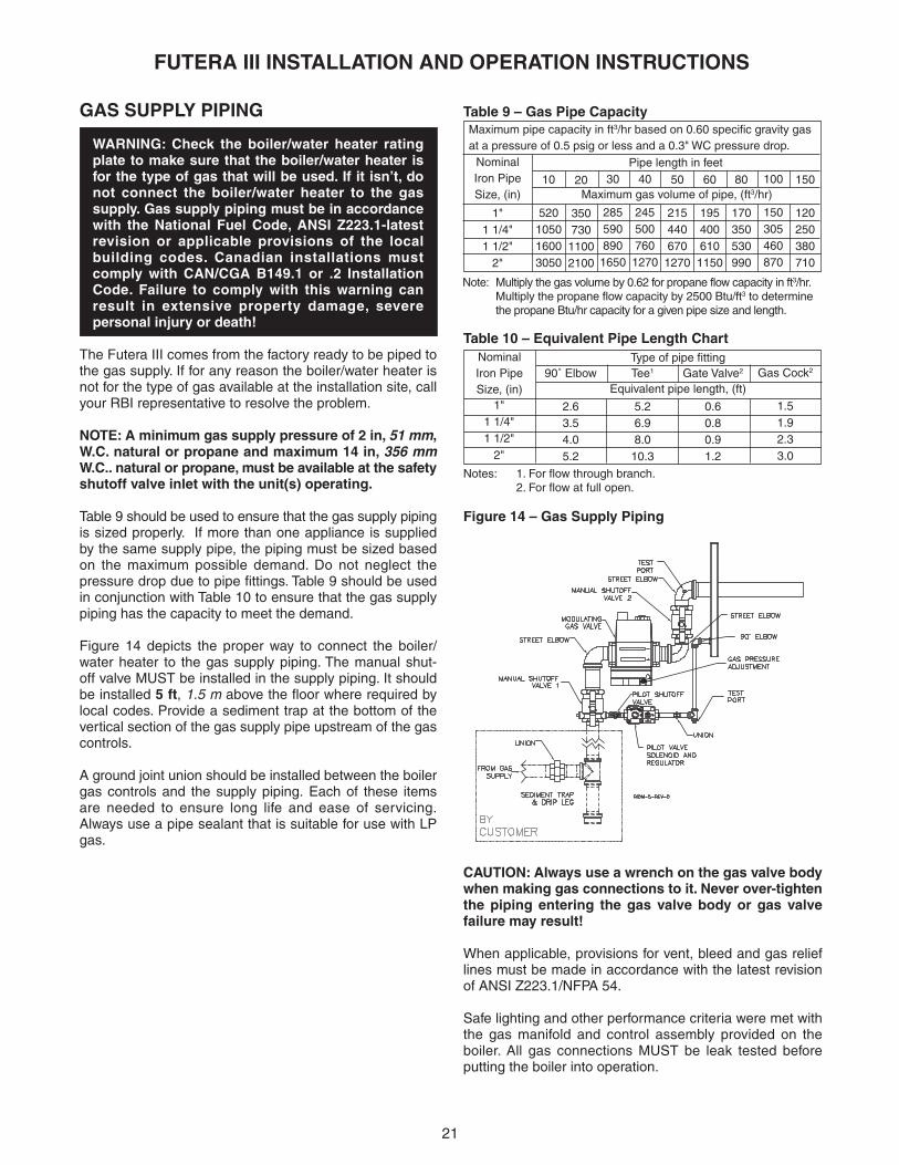
Figure 14 – Gas Supply Piping
CAUTION: Always use a wrench on the gas valve bodywhen making gas connections to it. Never over-tightenthe piping entering the gas valve body or gas valvefailure may result!
When applicable, provisions for vent, bleed and gas relieflines must be made in accordance with the latest revisionof ANSI Z223.1/NFPA 54.
Safe lighting and other performance criteria were met withthe gas manifold and control assembly provided on theboiler. All gas connections MUST be leak tested beforeputting the boiler into operation.
Note: Multiply the gas volume by 0.62 for propane flow capacity in ft3/hr.Multiply the propane flow capacity by 2500 Btu/ft3 to determinethe propane Btu/hr capacity for a given pipe size and length.
1"1 1/4"1 1/2"
2"
Type of pipe fitting
Equivalent pipe length, (ft)90˚ Elbow
2.63.54.05.2
Tee1
5.26.98.0
10.3
Gate Valve2
0.60.80.91.2
Gas Cock2
1.51.92.33.0
NominalIron PipeSize, (in)
Notes: 1. For flow through branch.2. For flow at full open.
NominalIron PipeSize, (in)
10
520105016003050
20
350730
11002100
30
2855908901650
40
2455007601270
50
215440670
1270
60
1954006101150
80
170350530990
100
150305460870
Maximum pipe capacity in ft3/hr based on 0.60 specific gravity gasat a pressure of 0.5 psig or less and a 0.3" WC pressure drop.
150
120250380710
Pipe length in feet
1"1 1/4"1 1/2"
2"
Maximum gas volume of pipe, (ft3/hr)
GAS SUPPLY PIPING
WARNING: Check the boiler/water heater ratingplate to make sure that the boiler/water heater isfor the type of gas that will be used. If it isn’t, donot connect the boiler/water heater to the gassupply. Gas supply piping must be in accordancewith the National Fuel Code, ANSI Z223.1-latestrevision or applicable provisions of the localbuilding codes. Canadian installations mustcomply with CAN/CGA B149.1 or .2 InstallationCode. Failure to comply with this warning canresult in extensive property damage, severepersonal injury or death!
The Futera III comes from the factory ready to be piped tothe gas supply. If for any reason the boiler/water heater isnot for the type of gas available at the installation site, callyour RBI representative to resolve the problem.
NOTE: A minimum gas supply pressure of 2 in, 51 mm,W.C. natural or propane and maximum 14 in, 356 mmW.C.. natural or propane, must be available at the safetyshutoff valve inlet with the unit(s) operating.
Table 9 should be used to ensure that the gas supply pipingis sized properly. If more than one appliance is suppliedby the same supply pipe, the piping must be sized basedon the maximum possible demand. Do not neglect thepressure drop due to pipe fittings. Table 9 should be usedin conjunction with Table 10 to ensure that the gas supplypiping has the capacity to meet the demand.
Figure 14 depicts the proper way to connect the boiler/water heater to the gas supply piping. The manual shut-off valve MUST be installed in the supply piping. It shouldbe installed 5 ft, 1.5 m above the floor where required bylocal codes. Provide a sediment trap at the bottom of thevertical section of the gas supply pipe upstream of the gascontrols.
A ground joint union should be installed between the boilergas controls and the supply piping. Each of these itemsare needed to ensure long life and ease of servicing.Always use a pipe sealant that is suitable for use with LPgas.

22
FUTERA III INSTALLATION AND OPERATION INSTRUCTIONS
WARNING: Never use an open flame to test for gasleaks. Always use an approved leak detectionmethod. Failure to comply with this warning cancause extensive property damage, severe personalinjury or death!
Whenever the gas supply piping is pressure tested theboiler/water heater gas controls must be protected. If thetest pressure is equal to, or less than 1/2 psig, 3.5 kPaisolate the boiler/water heater by closing it’s manual shutoff valve, see Figure 14. If the test pressure is greater than,or equal to 1/2 psig, 3.5 kPa, disconnect the boiler/waterheater and its individual shut-off valve.
ELECTRICAL WIRING
Electrical Power Connections
CAUTION: Label all wires prior to disconnection whenservicing controls. Wiring errors can cause improperand dangerous operation! Verify proper operation afterservicing.
ATTENTION: Au moment de l’entretien descommandes, étiquetez tous les fils avant de lesdébrancher. Des erreurs de câblage peuvent entraînerun fonctionnement inadéquat et dangereux. S’assurerque l’appareil fonctionne adéquatement une foisl’entretirn terminé.
The electrical connections to this boiler/water heater mustbe made in accordance with all applicable local codes andthe latest revision of the National Electrical Code, ANSI /NFPA-70. Installation should also conform with CSA C22.1Canadian Electrical Code Part I if installed in Canada.
Install a separate 120 volt 15 amp circuit for the boiler/waterheater. A properly rated shut-off switch should be locatedat the boiler/water heater. The boiler/water heater must begrounded in accordance with the authority havingjurisdiction, or if none, the latest revision of the NationalElectrical Code, ANSI/NFPA-70.
Line voltage field wiring of any controls or other devicesmust conform to the temperature limitation of type T wireat 95°F, 35°C above room temperature. Use copperconductors with a minimum size of #14 awg.
Refer to the wiring diagram supplied with the boiler/waterheater for proper wiring connections.
GENERAL OPERATION
WARNING: Before proceeding read and fullyunderstand the instructions contained in thismanual. Do not attempt to operate this boiler/waterheater if it has not been installed in accordancewith the guidelines set forth in this manual. Failureto comply with this warning can result in extensiveproperty damage, severe personal injury or death!
Should overheating occur or the gas supply fail to shut off,turn off the manual gas control valve to the appliance. Donot interrupt water flow through the boiler/water heater.
En cas de surchauffe ou si l’alimentation en gaz ne s’arrêtepas, fermez manuellement le robinet d’arrêt de l’admissionde gaz.
Hydronic Heating BoilersOpen the make-up water valve and slowly fill the boiler andall of the radiation with water. Ensure that all bleed anddrain valves are closed.
Adjust the make-up water pressure regulator so a minimum12 psig, 82.7 kPa system pressure is maintained at thehighest point in the system piping. If a make-up water pumpis used adjust it to maintain a minimum 12 psig, 82.7 kPasystem pressure.
Open the system bleed and drain valves, one at a time, topurge the air trapped in the heating system piping.
With the boiler off, run the system pump for at least 30minutes and bleed the system piping using the bleedvalves. If strainers are used in the system piping, the make-up water valve should be closed and the strainers checkedand cleaned.
The system expansion tank should be checked to ensurethat the correct water level in the tank is maintained. Thetank should be less than half full of water with the systemfull and adjusted to the correct operating pressure.
Star t the boiler as described in the “OPERATINGINSTRUCTIONS” section. Run the boiler for at least anhour. The system pump(s) and all radiation units must beoperated during this time. Ensure that the make-up watervalve is open.
Shut the boiler off and open the bleed valves to purge theair trapped in the heating system piping. Close the make-up water valve and check and clean the strainers andmake-up water pressure reducing valve.
Open the make-up water valve and adjust the systempressure if necessary. The system should be checked andbled after three days of operation.

23
FUTERA III INSTALLATION AND OPERATION INSTRUCTIONS
OPERATING INSTRUCTIONSFOR YOUR SAFETY READ BEFORE OPERATING.
POUR VOTRE SÉCURITÉ LISEZ AVANT DE METTRE ENMARCHE
A. This appliance is equipped with an ignition devicewhich automatically lights the pilot. Do not try to lightthe pilot by hand.
Cet appareil est muni d’un dispositif d’allumage quiallume automatiquement la veilleuse. Ne tentez pasd’allumer la veilleuse manuellement.
B. BEFORE OPERATING smell all around the appliancearea for gas. Be sure to smell next to the floor becausesome gas is heavier than air and will settle on the floor.
DANGER: Propane gas may not always be detectedby smell. Propane gas is heavier than air and cancollect in low areas.
Propane gas can ignite or explode if an ignitionsource is present and result in death, seriousinjury and property damage!
FOR YOUR SAFETY•Have only qualified licensed professionals install,service and maintain this appliance and your gassystem in accordance with all applicable codes.
• If you suspect a leak:1. Have everyone leave the building immediately.2. Do not attempt to light any appliance.3. Do not touch any electrical or electronic switches
in the building.4. Do not use any phone in the building.5. Call your gas supplier from a phone outside of the
building.6. If you cannot reach your gas supplier call the fire
department.
AVANT DE FAIRE FONCTIONNER, reniflez tout autour del’appareil pour déceler une odeur de gaz. Reniflez près duplancher, car certains gaz sont plus lourds que l’air etpeuvent s’accumuler au niveau du sol.
QUE FAIRE SI VOUS SENTEZ UNE ODEUR DE GAZ:• Ne pas tenter d’allumer d’appareil.• Ne touchez à aucun interrupteur; ne pas vous servir
des téléphones se trouvant dans le bâtiment.• Appelez immédiatement votre fournisseur de gaz
depuis un voisin. Suives les instructions du fournisseur.• Si vous ne pouvez rejoindre le fournisseur, appelez le
service de incendies.
C. Do not use this appliance if any part has been underwater. Immediately call a qualified service technicianto inspect the appliance and to replace any part of thecontrol system and any gas control that has beenunder water.
N’utilisez pas cet appareil s’il a été plongé dans l’eau,même partiellement. Faites inspecter l’appareil par untecnicien qualifié et remplacez toute partie du systèmede contrôle et toute commande qui ont été plongésdans l’eau.
CAUTION: To prevent being burned, stand clear of theboiler during ignition and don’t touch any hot metalparts!
Operating Instructions 1. STOP! Read the safety information above. If, at any
time, the appliance will not operate properly, followthe instructions “TO TURN OFF GAS TOAPPLIANCE”.
2. Set the operating control to off or its lowest setting.
3. Turn off all electric power to the appliance.
4. Close manual main shut-off valves 1 and 2 and thepilot gas shut-off valve, Figure 14.
5. Make sure that the gas supply piping has been purgedof air and that all gas joints up to the gas valve havebeen thoroughly checked for leaks.
Wait five (5) minutes to clear out any gas. Then smellfor gas, including near the floor. If you smell gas,STOP! Follow “B” in the safety information above (tothe left) on this label. If you don’t smell gas, go to thenext step.
6. Power appliance and turn the power switch on the sideof the boiler to “on”. If all interlocks are properly closed,the display will say “Standby Futera III”. If this is notthe case refer to the “DIAGNOSTICS” section forfurther information.
7. A minimum gas supply pressure of 2 in, 51 mm, W.C.natural of propane and max 14 in, 356 mm W.C.,natural of propane, must be available at the safetyshutoff valve inlet with the unit(s) operating.
8. Create a full input demand by jumping the AAterminals on control board at terminal strip J12.
9. The boiler will begin the start sequence.

24
FUTERA III INSTALLATION AND OPERATION INSTRUCTIONS
2. Mettez l’appareil à l’arrêt ou réglez celui-ci au minimum.
3. Coupez toute alimentation électrique de l’appareil.
4. Fermez manuellement les robinets d’arrêt principaux1 et 2 ainsi que le robinet d’arrêt de la veilleuse. Voirfigure 14.
5. Assurez-vous au préalable que la conduited’alimentation en gaz a été purgée et que tous sesraccords jusqu’au niveau du robinet sont exempts defuite.
6. Mettez l’appareil sous tension et tournez l’interrupteursitué sur le côté de la chaudière en position de marche.Si tous les interrupteurs de verrouillage sontconvenablement fermés, l’affichage doit indiquer«Standby Futera III». Si ce n’est pas le cas, reportez-vous à la section «DIAGNOSTIC».
7. Lorsque l’appareil est en marche, la pression du gaz àl’entrée du robinet d’arrêt de sécurité doit être au mini-mum de 2 po, 51 mm, CE, gaz naturel ou propane etau maximum de 14 po, 356 mm, CE, gaz naturel oupropane.
8. Créez une nette demande de chauffage au tableau decommandes en posant un cavalier sur les bornes AA(bornier J12).
9. La chaudière entamera la séquence de démarrage.
10. Surveillez le courant de flamme sur le régulateur dubrûleur Honeywell 7895C. Aucun courant de flamme nedoit être détecté et le 7895C devrait se verrouiller. Si uncourant de flamme est détecté avant le verrouillage du7895C, le câblage 120V du transformateur d’allumagedoit être inversé. Vérifiez à nouveau pour vous assurerqu’aucune flamme n’est détectée.
AVERTISSEMENT: Un câblage incorrect dutransformateur d’allumage peut provoquer uneexplosion entraînant de graves blessures ou la mortet causer d’importants dégâts matériel.
11. Ouvrez manuellement les robinets d’arrêt principaux 1et 2 ainsi que le robinet d’arrêt de la veilleuse. Voirfigure 14.
12. Remettez à zéro le régulateur Honeywell 7895C. Lachaudière commencera la séquence de démarrage.
13. Lorsque l’affichage indique ́ «PILOT RUNNING» et quele courant de flamme est de 5V c.c., commutez leHoneywell 7895C en mode ́ «test». Ceci permettra dele maintenir en position d’allumage.
14. Réglez la pression de la veilleuse tel qu’indiqué à lasection «VÉRIFICATION ET RÉGLAGES».
15. Commutez à nouveau le Honeywell 7895C en mode«marche».
10. Monitor the flame current on the Honeywell BurnerControl 7895C. No flame current should be detectedand the 7895C should lock out. If flame current isdetected at any time up to the 7895C locking out, the120V wiring on the ignition transformer must bereversed. Test again to insure that no flame is detected.
WARNING: Improper wiring of the ignitiontransformer can result in an explosion causingextensive property damage, severe personal injuryor death!
11. Open the manual main shut-off valves 1 and 2 and thepilot gas shut-off valve, Figure 14.
12. Reset the Honeywell 7895C. The boiler will begin thestart sequence.
13. When the main display reads “PILOT RUNNING” andthe flame current is 5 VDC, switch the Honeywell7895C to the “test” position. This will hold theHoneywell 7895C in its ignition state.
14. Adjust the pilot pressure per the “CHECKING &ADJUSTMENTS”.
15. Switch the Honeywell 7895C back to “run”.
16. Allow the boiler to establish main flame and modulateto full input. Check the input rate per the “CHECKING& ADJUSTMENTS” section.
17. Move the slide switch below the display to “Min Hold”,low fire.
18. Set manifold pressure at elbow before entering cabinetto -2.95" WC (± -.1" WC) at high fire.
19. Allow the boiler to modulate to min input. Observe theburner to ensure that it is not operating in an infraredcondition. Take a flue gas sample using a calibratedanalyzer. Use a 2.5mm, 3/32" allen wrench to adjustthe gas valve to produce a CO2 of approximately 8.5%for natural gas and 10.5% for propane. Make small 10-degree adjustments and wait until the CO2 readingssettle before making further adjustments.
20. When all adjustments are finished, move the slideswitch below the display to the “Run” position andremove input by opening jumper AA.
21. The boiler allows for four modes of operation. Refer tothe “MPA STAGING CONTROL” for further information.
Consignes d’utilisation 1. ATTENTION! Lisez les mises en garde ci-dessus. Si
vous constatez une anomalie quelconque dans lefonctionnement de l’appareil, suivez les instructions dela section «COMMENT COUPER L’ALIMENTATION DEGAZ DE L’APPAREIL».
25
FUTERA III INSTALLATION AND OPERATION INSTRUCTIONS
16. Laisser la chaudière compléter la séquence d’allumageet atteindre son plein régime. Vérifiez le débit telqu’indiqué à la section «VÉRIFICATION ETRÉGLAGES».
17. Déplacez le curseur situé sous l’écran d’affichage, à laposition «Min Hold», soit faible régime.
18. Laissez la chaudière atteindre son régime minimum.Observez le brûleur et vérifiez qu’il ne fonctionne pasen infrarouge. Prélevez un échantillon de gaz de com-bustion à l’aide d’un analyseur calibré. Réglez le robinetde gaz au moyen d’une clé Allen de 2,5mm (3/32 po)afin de produire une concentration de CO2 d’environ8,5% pour du gaz naturel et de 10,5% pour du gazpropane. Procédez par écarts de 10 degrés et attendezque la lecture du CO2 se stabilise avant chaque nouveauréglage.
19. Lorsque tous les réglages ont été effectués, glissez lecurseur situé sous l’écran d’affichage à la position«Run» et mettez fin à la demande en retirant le cava-lier des bornes AA.
20. La chaudière offre quatre modes d’opération. Reportez-vous à la section ´«MPA STAGING CONTROL» pourplus de détails.
To Turn Off Gas To Appliance1. Set the operating control or thermostat to its lowest
setting.2. Turn off all electric power to the appliance if service is
to be performed.3. Close the manual main and pilot gas shut-off valves.
COMMENT COUPER L’ADMISSION DE GAZ DEL’APAREIL1. Réglez le thermostat à la température la plus basse.2. Coupez l’alimentation électrique de l’appareil s’il faut
procéder à l’entretien.3. Fermer la vanne manuelle d’arrêt d’alimintation de gaz.
CHECKING & ADJUSTMENTS
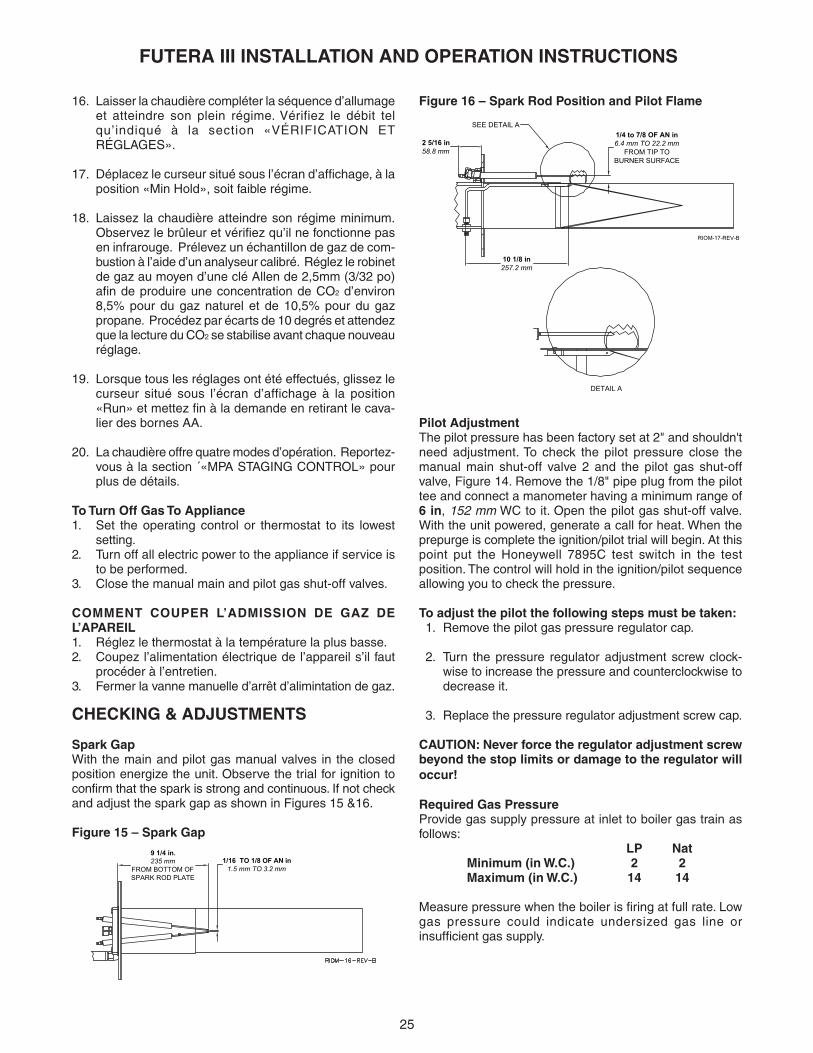
Spark GapWith the main and pilot gas manual valves in the closedposition energize the unit. Observe the trial for ignition toconfirm that the spark is strong and continuous. If not checkand adjust the spark gap as shown in Figures 15 &16.
Figure 15 – Spark Gap
Figure 16 – Spark Rod Position and Pilot Flame
Pilot AdjustmentThe pilot pressure has been factory set at 2" and shouldn'tneed adjustment. To check the pilot pressure close themanual main shut-off valve 2 and the pilot gas shut-offvalve, Figure 14. Remove the 1/8" pipe plug from the pilottee and connect a manometer having a minimum range of6 in, 152 mm WC to it. Open the pilot gas shut-off valve.With the unit powered, generate a call for heat. When theprepurge is complete the ignition/pilot trial will begin. At thispoint put the Honeywell 7895C test switch in the testposition. The control will hold in the ignition/pilot sequenceallowing you to check the pressure.
To adjust the pilot the following steps must be taken: 1. Remove the pilot gas pressure regulator cap.
2. Turn the pressure regulator adjustment screw clock-wise to increase the pressure and counterclockwise todecrease it.
3. Replace the pressure regulator adjustment screw cap.
CAUTION: Never force the regulator adjustment screwbeyond the stop limits or damage to the regulator willoccur!
Required Gas PressureProvide gas supply pressure at inlet to boiler gas train asfollows:
LP NatMinimum (in W.C.) 2 2Maximum (in W.C.) 14 14
Measure pressure when the boiler is firing at full rate. Lowgas pressure could indicate undersized gas line orinsufficient gas supply.
1/16 TO 1/8 OF AN in1.5 mm TO 3.2 mm
9 1/4 in.235 mm
FROM BOTTOM OFSPARK ROD PLATE
RIOM-17-REV-B
SEE DETAIL A
1/4 to 7/8 OF AN in6.4 mm TO 22.2 mm
FROM TIP TOBURNER SURFACE
DETAIL A
2 5/16 in58.8 mm
10 1/8 in257.2 mm

26
FUTERA III INSTALLATION AND OPERATION INSTRUCTIONS
“Static and operating gas pressure required at the gasvalve inlet is between 2" W.C. and 14" W.C. for natural gasand 2" W.C. and 14" W.C. propane. If the gas pressure isabove this limit, a lock-up style regulator suitable for deadend service such as an Equimeter or Fisher must beinstalled to prevent increase (creep) of gas pressure whenthe units are not operating. This pressure regulator(supplied by others) may be installed at the serviceentrance to each unit or a “master” regulator sized tohandle multiple units may be utilized. Consult local gasutility or regulator manufacturer for recommendations tomeet specific job site requirements.”
Input Rate, Natural GasGas appliances are rated based on sea level operation withno adjustment required at elevations up to 2000 ft, 610 m.At elevations above 2000 ft, 610 m input ratings shouldbe reduced by 4% for each 1000 ft, 305 m.
Check the input rate as follows:1. Turn off all other gas appliances that use the same gas
meter as the boiler/water heater.2. Call your gas supplier and ask for the heating value
of the gas.3. Start the boiler/water heater and let it run for 15
minutes.4. Using the gas meter and a stopwatch, clock the time
that it takes to burn 10 ft3, 0.28 m3 of gas and dividethis time by 10.
5. Insert the heating value and the time, in seconds, intothe formula below.
6. Input = (heating value, Btu/hr)(3600)/(time, seconds)7. If the computed rate deviates by more than 5% from
the rated input value of the unit, consult factory.
CAUTION: Never increase the input to the boiler/waterheater above that for which it is rated. Doing so cancause premature failure of the boiler!
CONTROL DESCRIPTION
Low Water CutoffIf the boiler is to be installed above radiation or if requiredby other codes or regulations, install a low water cutoff inappropriate piping. Wire the switch and any externalcontrols in series to the "Interlock" contacts in the junctionbox (see the attached Connection Diagrams for details).Ensure that the low water cutoff device(s) will functionproperly.
Operating ControlThe preferred control setting for potable hot water is 130°F,54°C. The operating control should be set to the lowestsetting that will satisfy the consumer's needs.
WARNING: Setting the thermostat or operationcontrol too high can result in scalding resulting insevere personal injury!
High Limit (Aquastat)The high limit is located in the top control area of the boiler/water heater. A remote capillary bulb is run to a well onthe outlet side of the supply header. The high limit can bereset by depressing the red button.
The water heater high limit should be set a minimum of20°F, 11°C higher than the operating control. Refer to theHOT WATER SUPPLY section for the proper supply watertemperature.
Flow SwitchA flow switch is provided in the water outlet piping toprevent the boiler/water heater from firing without adequatewater flow through the heat exchanger.
MPA STAGING CONTROLThis boiler control is mounted on the front panel of theboiler/water heater. It utilizes various temperature sensorsto calculate boiler/water heater demand and adjust themodulation as needed. Various features of the control canbe adjusted from the 3-button panel on the controller. Tochange settings of the modulation controller, press and holdall three buttons approximately 2 seconds until the “adjust”screen appears, then release them. The modulating controlprovides 4 modes of operation based on the requirementsof the system. Each mode is defined below.
At the rear of the controller, there is a single DIP switch.This switch is factory set to provide a “lockout” withminimum adjustment capabilities in the field. However, forexperienced installers and operators, changing theseswitch settings can offer many fine-tuning features. Pleaseconsult the factory for assistance.
CAUTION: DO NOT change DIP switch or controllersettings unless you have completely read andunderstood this document and the controlmanufacturer’s instructions. Doing otherwise will leadto improper modulating control.
Installer Level Settings
Modes of Operation (MODE): The control allows for fourmodes of operation in order to define the control operationand piping arrangement used.
Mode 1: Setpoint Control. Parallel Piping. The Futera III ispiped in parallel with the system. The rate of modulation iscontrolled to provide a setpoint temperature at the boiler/water heater outlet, whenever there is a heat demandpresent.
Mode 2: Setpoint Control.Primary/Secondary Piping.TheFutera III is piped in a primary/secondary configuration. Anadditional system sensor is required to properly control thesystem supply (primary loop) temperature. The rate ofmodulation is controlled to provide the setpoint temperaturein the primary loop.
27
FUTERA III INSTALLATION AND OPERATION INSTRUCTIONS
Mode 3: Domestic Hot Water (DHW) generation. TheFutera III is piped in parallel with the storage tank. Anadditional sensor is required to monitor the tanktemperature. The rate of modulation is controlled tomaintain the desired DHW tank temperature.
DHW Operation: A DHW demand is generated wheneverthe temperature sensed by the DHW sensor drops belowthe programmed tank target temperature by 1/2 the tankdifferential, adjustable from 2 to 10˚F. The demand remainsuntil the temperature sensed by the DHW sensor risesabove the programmed tank target temperature plus 1/2the tank differential.
Mode 4: External Boiler Control: The Modulating BoilerControl allows for an external boiler control to operate theboiler. Factory installed terminals are supplied inside thefront cabinet of the Futera III. These include boiler startcontacts, 4-20mA modulating signal contacts, and boileralarm dry contacts. A sequencer or controller must provideboth boiler start contacts and a modulating signal forexternal control of the boiler/water heater. The modulatingboiler control will display inlet and outlet temperatures aswell as control the pump delay.
Boiler Target Temperature (BOIL TARGET)The boiler target temperature is determined from the modeof operation. The control displays the temperature that it iscurrently trying to maintain at the operating sensor as BOILTARGET in the View menu. The operating sensor for mode1 is the outlet sensor. Mode 2 is the system supply sensor.Mode 3 is the tank sensor. There is no boiler targettemperature generated in mode 4.
Boiler Differential (BOIL DIFF)The boiler is operated with a differential in order to reduceshort cycling. The boiler differential is divided around theboiler target temperature. The control will initiate the boiler/water heater when the operating sensor is 1/2 of thedifferential setting below the boiler target temperature, andwill stop the boiler/water heater once the modulating outputis at the minimum modulation setting and the watertemperature at the operating sensor is 1/2 of the differentialsetting above the boiler target temperature.
Boiler Purge (PMP DLY)After a demand is satisfied, the control continues to operatethe boiler pump for a period of time. The length of time thatthe boiler pump continues to run is based on the PMP DLYsetting. Once the boiler turns off, the control keeps theboiler pump running for the time selected. This settingallows purging of any excess heat out of the boiler afterthe boiler is shut off.
When PMP DLY is set to OFF, there is no purging. WhenPMP DLY is set to ON, the pump runs continuously.
Tank Target Temperature (TANK TARGET), Mode 3 OnlyThe TANK TARGET setting is used to set the desired DHWtank temperature.
Tank Differential (TANK DIFF), Mode 3 OnlyA differential setting that operates 1/2 above and below theTANK TARGET is selectable using the TANK DIFF item inthe Adjust menu.
Advanced Level Settings
CAUTION: These settings are not to be changed unlessthe manufacturer is contacted. Unstable or evendangerous operation of the boiler/water heater couldresult.
Motor Speed: The control includes a motor speedadjustment, which sets the speed of the actuating motorthat provides firing modulation. Default value is 30.
Start Modulation: The start modulation is the firingrate recommended for proper burner ignition. Default valueis 4%.
Minimum Modulation: The minimum modulation is thefiring rate the control will modulate down to duringoperation. This setting is based on the analog output signal,which provides low fire. Default value is 0%.
Fire Delay: The fire delay is the time that the control waitsat the Start Modulation output. The delay is the result of apre-purge and trial ignition built into the boiler's safetycircuits. Default value is 20 sec.
Boiler Mass: The boiler mass setting allows the installer toadjust the control to the thermal mass of different types ofheat sources used. The boiler mass setting automaticallydetermines the rate of modulation. A higher thermal masssetting provides slower modulation, while a lower thermalmass provides faster modulation. Default value is 1.
Boiler Minimum: The boiler minimum is the lowest watertemperature that the control is allowed to use as a boilertarget temperature. For boiler operation the default valueis 140˚F. For domestic hot water operation the default valueis 120˚F.
Boiler Maximum: The boiler maximum is the highest watertemperature that the control is allowed to use as a boilertarget temperature. The default value is 210˚F.
DIAGNOSTICSThe Futera III has a display that indicates the sequence ofoperation. The display will also list faults should the unit failto operate. An explanation of each status message and faultis listed below.
STANDBY FUTERA III: Indicates that power is beingsupplied to the unit and there is no call for heat.
STANDBY START DEMAND: Indicates that the boilerhas a call for heat and that all safety limits have proved.

28
FUTERA III INSTALLATION AND OPERATION INSTRUCTIONS
STANDBY REMOTE DISABLED: Indicates that the boilerstart interlock is open. This usually indicates that either abuilding management system or a remote thermostat hasdisabled the boiler.
PREPURGE: The boiler performs a 10 second fan pre-purgeto push out any gases that might still be in the combustionchamber before the boiler fires.
PILOT RUNNING: This is displayed during the pilot flameestablishing period.
MAIN MODULATION: This indicates when the boiler hassuccessfully established a pilot flame and the main valvehas opened. The screen will also display the rate ofmodulation as a percentage.
POSTPURGE: The boiler performs a 10 second fan post-purge to push out any gases that are still in the combustionchamber after the flame is extinguished.
HONEYWELL ALARM: Indicates that there is a call for heatand the Honeywell Burner Control is locked out. Either it islocked out due to a flame failure, or it is malfunctioning. Pressthe reset button on the Burner Control.
LOCKOUT HIGH LIMIT: Indicates that the high limit controllerhas opened due to a high outlet water temperature. To resetpress the red button on the high limit controller inside theupper cabinet. The high limit should be set at least 20°F abovethe target temperature for the boiler.
LOCKOUT AIR FLOW: Indicates that there is inadequateairflow through the boiler. Check the air filter for debris, or forany materials obstructing the flue outlet. Check the blockedflue switch, it may have to be reset.
LOCKOUT GAS PRESSURE: Indicates that either the lowgas or high gas pressure switches have opened. Theseswitches are manual reset.
LOCKOUT WATER LIMIT: Indicates that the water flow switchis not proving adequate water flow through the boiler or thelow water cutoff is sensing low water.
LOCKOUT HI-LIMIT & WATER LIMIT: Indicates that both thehigh-limit and water limit interlocks are open.
LOCKOUT HI-LIMIT & GAS PRESSURE: Indicates that boththe high-limit and gas pressure interlocks are open.
MULTIPLE INTERLOCK: Indicates that there are more than2 interlocks that are open. Check the high-limit, gas pressureswitches, and water flow switch.
LOCKOUT TEKTRA ALARM: Indicates a problem with theRBI Modulating Control. This is usually the result of a shortor open circuit in one of the temperature sensors. Inspectthe sensor in question to see if it is connected properly. Also,check to see if the sensor is shorted or open using anohmmeter.
MAINTENANCE
WARNING: Disconnect electrical power and closethe manual gas shut off valve before performingmaintenance or severe personal injury may result!
CAUTION: Servicing, inspection and adjustment mustbe done by a trained technician in accordance with allapplicable local and national codes. Improper servicingor adjustment can damage the boiler/water heater!
The boiler/water heater must be cleaned and inspected atleast once a year and before each heating season. Makesure that the burner and ignition components are free fromdust, soot, dirt, corrosion or other deposits that would impairthe boiler/water heater ‘s performance. Refer to page 31 and32 for component identification.
CAUTION: Improper burner servicing can result inpremature burner failure voiding the warranty!
Burner Removal1. Close the manual shutoff valves in the gas supply line
and turn off electrical power to the boiler/water heater.2. Remove the jacket top panel.3. Disconnect the wires to the fan and remove the four
bolts that secure the fan to the transition piece.4. Remove wires from the spark rods and remove the UV
sense from the transition piece.5. Disconnect the compression nut at the back of the
transition piece to remove pilot gas tubing.6. Remove the four nuts holding the transition piece to the
heat exchanger.7. Lift and remove the transition piece and burner together
from the boiler/water heater, taking care not to damagethe spark rods and or their alignment.
8. Disconnect the compression nut from the inside of thetransition piece.
9. Remove the transition piece, taking care not to damagethe spark rods and or their alignment.
Heat Exchanger Inspection1. Close the manual shutoff valves in the gas supply lines
and turn off electrical power to the boiler/water heater.2. Remove burner following the instructions in the Burner
Removal section.3. Remove the front jacket panel and combustion chamber
door.4. Inspect the inside and outside of the heat exchanger
for signs of damage, sooting or corrosion.5. The outside surfaces of the copper tubes should be free
of any soot deposits. A slight black smudge is normal withsome types of gases. Black soot indicates poorcombustion. Green deposits indicate condensation dueto low return water temperatures. In either case the heatexchanger must be cleaned thoroughly and the problemresolved before the boiler/water heater is returned toservice.
6. If there are no signs of damage, sooting or corrosion,reassemble the unit following the previous steps inreverse order.
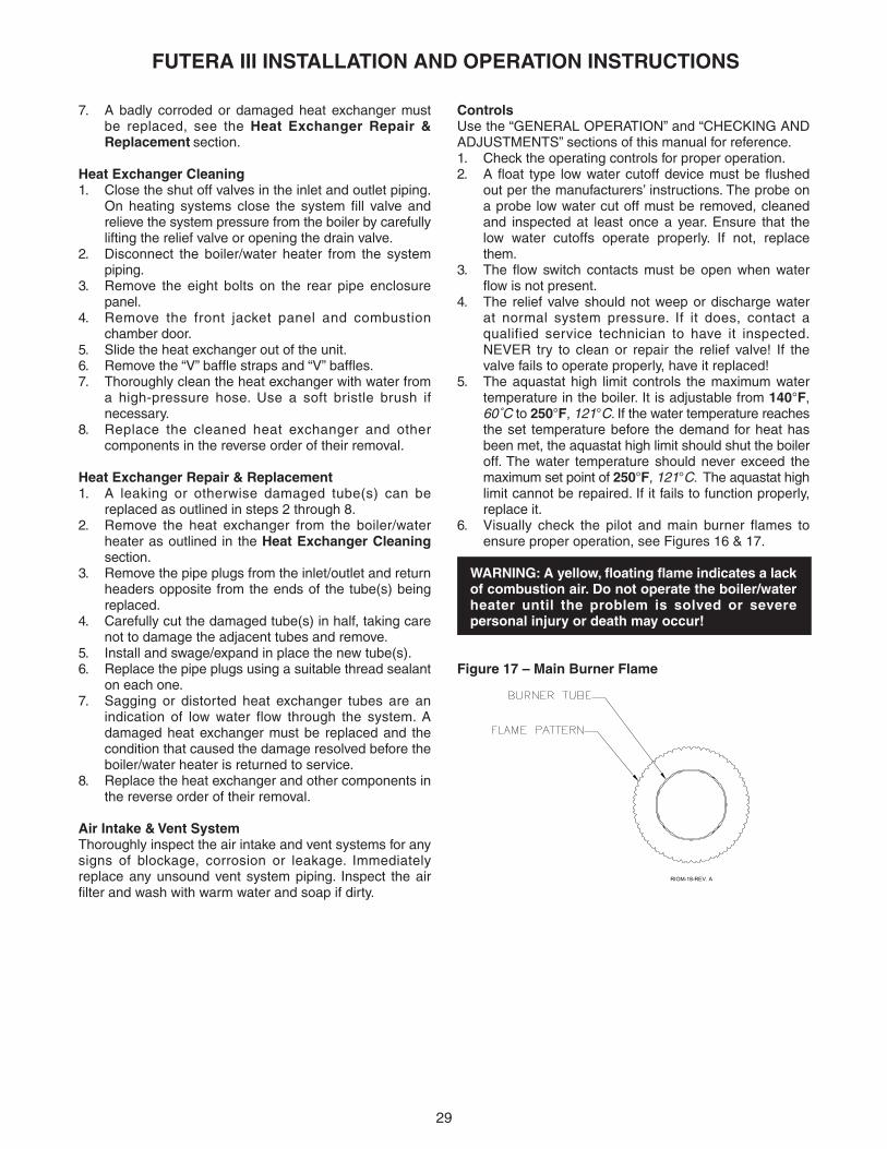
29
FUTERA III INSTALLATION AND OPERATION INSTRUCTIONS
7. A badly corroded or damaged heat exchanger mustbe replaced, see the Heat Exchanger Repair &Replacement section.
Heat Exchanger Cleaning1. Close the shut off valves in the inlet and outlet piping.
On heating systems close the system fill valve andrelieve the system pressure from the boiler by carefullylifting the relief valve or opening the drain valve.
2. Disconnect the boiler/water heater from the systempiping.
3. Remove the eight bolts on the rear pipe enclosurepanel.
4. Remove the front jacket panel and combustionchamber door.
5. Slide the heat exchanger out of the unit.6. Remove the “V” baffle straps and “V” baffles.7. Thoroughly clean the heat exchanger with water from
a high-pressure hose. Use a soft bristle brush ifnecessary.
8. Replace the cleaned heat exchanger and othercomponents in the reverse order of their removal.
Heat Exchanger Repair & Replacement1. A leaking or otherwise damaged tube(s) can be
replaced as outlined in steps 2 through 8.2. Remove the heat exchanger from the boiler/water
heater as outlined in the Heat Exchanger Cleaningsection.
3. Remove the pipe plugs from the inlet/outlet and returnheaders opposite from the ends of the tube(s) beingreplaced.
4. Carefully cut the damaged tube(s) in half, taking carenot to damage the adjacent tubes and remove.
5. Install and swage/expand in place the new tube(s).6. Replace the pipe plugs using a suitable thread sealant
on each one.7. Sagging or distorted heat exchanger tubes are an
indication of low water flow through the system. Adamaged heat exchanger must be replaced and thecondition that caused the damage resolved before theboiler/water heater is returned to service.
8. Replace the heat exchanger and other components inthe reverse order of their removal.
Air Intake & Vent SystemThoroughly inspect the air intake and vent systems for anysigns of blockage, corrosion or leakage. Immediatelyreplace any unsound vent system piping. Inspect the airfilter and wash with warm water and soap if dirty.
ControlsUse the “GENERAL OPERATION” and “CHECKING ANDADJUSTMENTS” sections of this manual for reference.1. Check the operating controls for proper operation.2. A float type low water cutoff device must be flushed
out per the manufacturers’ instructions. The probe ona probe low water cut off must be removed, cleanedand inspected at least once a year. Ensure that thelow water cutoffs operate properly. If not, replacethem.
3. The flow switch contacts must be open when waterflow is not present.
4. The relief valve should not weep or discharge waterat normal system pressure. If it does, contact aqualified service technician to have it inspected.NEVER try to clean or repair the relief valve! If thevalve fails to operate properly, have it replaced!
5. The aquastat high limit controls the maximum watertemperature in the boiler. It is adjustable from 140°F,60˚C to 250°F, 121°C. If the water temperature reachesthe set temperature before the demand for heat hasbeen met, the aquastat high limit should shut the boileroff. The water temperature should never exceed themaximum set point of 250°F, 121°C. The aquastat highlimit cannot be repaired. If it fails to function properly,replace it.
6. Visually check the pilot and main burner flames toensure proper operation, see Figures 16 & 17.
WARNING: A yellow, floating flame indicates a lackof combustion air. Do not operate the boiler/waterheater until the problem is solved or severepersonal injury or death may occur!
Figure 17 – Main Burner Flame
RIOM-18-REV. A

30
FUTERA III INSTALLATION AND OPERATION INSTRUCTIONS
“Standby Futera III” is not shown. Ensure that proper voltage is being supplied to the unit.Inspect the circuit breaker for the boiler/water heater circuit.Ensure that the power switch operates properly and iswired correctly.
Lockout high limit is displayed with a call for heat. Check the high limit control, press red button to reset.High limit should be set at least 20°F, 11°C above setpointtemperature.
Lockout gas pressure is displayed with a call for heat. Ensure that the manual main gas valve is open.Ensure that there is sufficient gas pressure supplyingthe boiler.Check pressure setting on the low gas pressureswitch.
Lockout water limit is displayed with a call for heat. Ensure that there is sufficient water flow through theboiler.
Lockout Tektra alarm is displayed with a call for heat. There is a problem with the Tekmar operating control.Check temperature sensors to see if connected properly.Check sensors for open or shorts using an ohmmeter.
TROUBLE-SHOOTING
OPERATIONAL PROBLEM CORRECTIVE ACTION

31
FUTERA III INSTALLATION AND OPERATION INSTRUCTIONS
Figure 18 – Exploded View
RIO
M-2
0-R
EV
. B
SE
E V
IEW
"A
"
SE
E V
IEW
"B
"
15C
15B
SE
E V
IEW
"C
"

32
FUTERA III INSTALLATION AND OPERATION INSTRUCTIONS
VIE
W: B
RO
TA
TE
D V
IEW
16
18
VIE
W: A
VIE
W: C
RIO
M-3
7-R
EV
-B
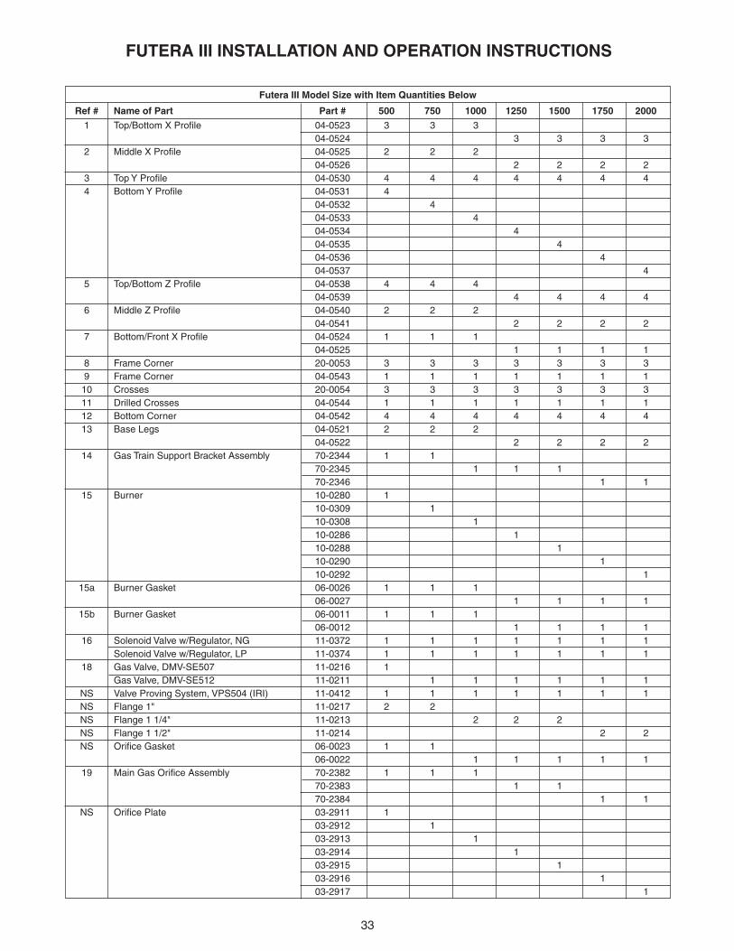
33
FUTERA III INSTALLATION AND OPERATION INSTRUCTIONS
1 Top/Bottom X Profile 04-0523 3 3 304-0524 3 3 3 3
2 Middle X Profile 04-0525 2 2 204-0526 2 2 2 2
3 Top Y Profile 04-0530 4 4 4 4 4 4 44 Bottom Y Profile 04-0531 4
04-0532 404-0533 404-0534 404-0535 404-0536 404-0537 4
5 Top/Bottom Z Profile 04-0538 4 4 404-0539 4 4 4 4
6 Middle Z Profile 04-0540 2 2 204-0541 2 2 2 2
7 Bottom/Front X Profile 04-0524 1 1 104-0525 1 1 1 1
8 Frame Corner 20-0053 3 3 3 3 3 3 39 Frame Corner 04-0543 1 1 1 1 1 1 110 Crosses 20-0054 3 3 3 3 3 3 311 Drilled Crosses 04-0544 1 1 1 1 1 1 112 Bottom Corner 04-0542 4 4 4 4 4 4 413 Base Legs 04-0521 2 2 2
04-0522 2 2 2 214 Gas Train Support Bracket Assembly 70-2344 1 1
70-2345 1 1 170-2346 1 1
15 Burner 10-0280 110-0309 110-0308 110-0286 110-0288 110-0290 110-0292 1
15a Burner Gasket 06-0026 1 1 106-0027 1 1 1 1
15b Burner Gasket 06-0011 1 1 106-0012 1 1 1 1
16 Solenoid Valve w/Regulator, NG 11-0372 1 1 1 1 1 1 1Solenoid Valve w/Regulator, LP 11-0374 1 1 1 1 1 1 1
18 Gas Valve, DMV-SE507 11-0216 1Gas Valve, DMV-SE512 11-0211 1 1 1 1 1 1
NS Valve Proving System, VPS504 (IRI) 11-0412 1 1 1 1 1 1 1NS Flange 1" 11-0217 2 2NS Flange 1 1/4" 11-0213 2 2 2NS Flange 1 1/2" 11-0214 2 2NS Orifice Gasket 06-0023 1 1
06-0022 1 1 1 1 119 Main Gas Orifice Assembly 70-2382 1 1 1
70-2383 1 170-2384 1 1
NS Orifice Plate 03-2911 103-2912 103-2913 103-2914 103-2915 103-2916 103-2917 1
Futera III Model Size with Item Quantities Below
Ref # Name of Part Part # 500 750 1000 1250 1500 1750 2000

34
FUTERA III INSTALLATION AND OPERATION INSTRUCTIONS
NS Firing Valve 3/4" 11-0461 1 1 1 1 1 1 120 Ball Valve 11-0395 1 1 1 1 1 1 121 Firing Valve, 1" 11-0456 1 1
Firing Valve, 1 1/4" 11-0457 1 1 1Firing Valve, 1 1/2" 11-0458 1 1
22 "A" Valve, 1" 11-0465 1 1"A" Valve, 1 1/4" 11-0466 1 1 1"A" Valve, 1 1/2" 11-0467 1 1
23 Blower, Fasco 7043 12-0016 1 1 1Blower, Fasco 7035 12-0017 1 1 1 1
NS Air Orifice 14-0099 1 1 1 1 1 1 124 Mixing Box 20-0051 1 1 1
20-0052 1 1 1 124a Airbox Mounting Assembly 70-2309 1 1 1 1 1 1 124b Gasket 06-0045 1 1 1 1 1 1 125 Flow Switch 14-0203 1 1 1 1 1 1 126 Frequency Drive, KBVF-14W 15-0227 1 1 1
Frequency Drive, KBVF26D 15-0226 1 1 1 127 Jacket Top Panel 70-2412 1 1 1
70-2413 1 1 1 128 Upper Rear Panel 70-2414 1 1 1
70-2415 1 1 1 129 Rear Pipe Enclosure Assembly 70-2333 1 1 1
70-2334 1 1 1 130 Lower Rear Jacket Panel 03-2822 1
03-2823 103-2824 103-2825 103-2826 103-2827 103-2828 1
31 Upper Left Jacket Panel 03-2831 1 1 103-2832 1 1 1 1
32 Upper Right Jacket Panel 03-2833 1 1 103-2834 1 1 1 1
33 Lower Left & Right Jacket Panel 03-2835 203-2836 203-2837 203-2838 203-2839 203-2840 203-2841 2
34 Upper Front Jacket Panel 70-2317 1 1 170-2318 1 1 1 1
35 Lower Front Jacket Panel 70-2365 170-2366 170-2367 170-2368 170-2369 170-2370 170-2371 1
36 Combustion Chamber Top Panel 70-2356 1 1 170-2357 1 1 1 1
37 Combustion Chamber Rear/Side Panel 70-2319 170-2320 170-2321 170-2322 170-2323 170-2324 170-2325 1
Futera III Model Size with Item Quantities Below
Ref # Name of Part Part # 500 750 1000 1250 1500 1750 2000
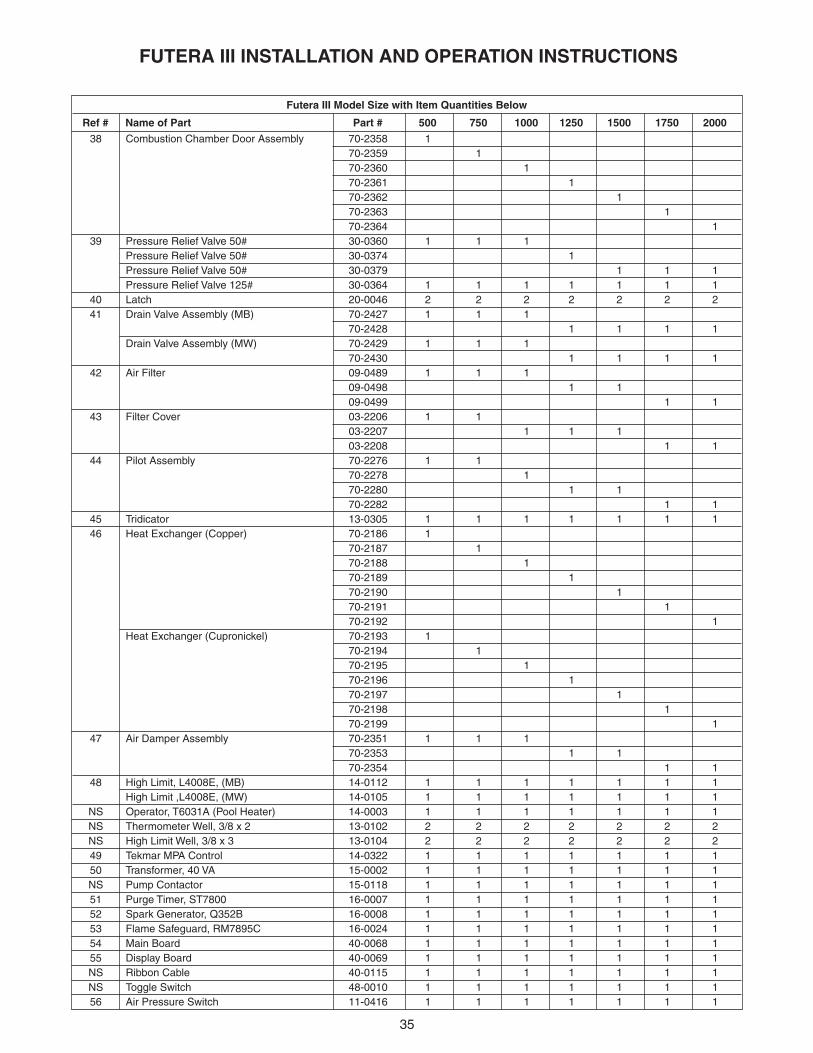
35
FUTERA III INSTALLATION AND OPERATION INSTRUCTIONS
38 Combustion Chamber Door Assembly 70-2358 170-2359 170-2360 170-2361 170-2362 170-2363 170-2364 1
39 Pressure Relief Valve 50# 30-0360 1 1 1Pressure Relief Valve 50# 30-0374 1Pressure Relief Valve 50# 30-0379 1 1 1Pressure Relief Valve 125# 30-0364 1 1 1 1 1 1 1
40 Latch 20-0046 2 2 2 2 2 2 241 Drain Valve Assembly (MB) 70-2427 1 1 1
70-2428 1 1 1 1Drain Valve Assembly (MW) 70-2429 1 1 1
70-2430 1 1 1 142 Air Filter 09-0489 1 1 1
09-0498 1 109-0499 1 1
43 Filter Cover 03-2206 1 103-2207 1 1 103-2208 1 1
44 Pilot Assembly 70-2276 1 170-2278 170-2280 1 170-2282 1 1
45 Tridicator 13-0305 1 1 1 1 1 1 146 Heat Exchanger (Copper) 70-2186 1
70-2187 170-2188 170-2189 170-2190 170-2191 170-2192 1
Heat Exchanger (Cupronickel) 70-2193 170-2194 170-2195 170-2196 170-2197 170-2198 170-2199 1
47 Air Damper Assembly 70-2351 1 1 170-2353 1 170-2354 1 1
48 High Limit, L4008E, (MB) 14-0112 1 1 1 1 1 1 1High Limit ,L4008E, (MW) 14-0105 1 1 1 1 1 1 1
NS Operator, T6031A (Pool Heater) 14-0003 1 1 1 1 1 1 1NS Thermometer Well, 3/8 x 2 13-0102 2 2 2 2 2 2 2NS High Limit Well, 3/8 x 3 13-0104 2 2 2 2 2 2 249 Tekmar MPA Control 14-0322 1 1 1 1 1 1 150 Transformer, 40 VA 15-0002 1 1 1 1 1 1 1NS Pump Contactor 15-0118 1 1 1 1 1 1 151 Purge Timer, ST7800 16-0007 1 1 1 1 1 1 152 Spark Generator, Q352B 16-0008 1 1 1 1 1 1 153 Flame Safeguard, RM7895C 16-0024 1 1 1 1 1 1 154 Main Board 40-0068 1 1 1 1 1 1 155 Display Board 40-0069 1 1 1 1 1 1 1NS Ribbon Cable 40-0115 1 1 1 1 1 1 1NS Toggle Switch 48-0010 1 1 1 1 1 1 156 Air Pressure Switch 11-0416 1 1 1 1 1 1 1
Futera III Model Size with Item Quantities Below
Ref # Name of Part Part # 500 750 1000 1250 1500 1750 2000

36
FUTERA III INSTALLATION AND OPERATION INSTRUCTIONS
57 Blocked Flue Switch 11-0411 1 1 1 1 1 1 1NS Terminal Block 6P 48-0157 1 1 1 1 1 1 1NS Terminal Block 4P 48-0161 1 1 1 1 1 1 1NS Mini Peeper, C7027A 16-0009 1 1 1 1 1 1 1NS UV Amplifier, R7849A 16-0006 1 1 1 1 1 1 1NS Base, Q7800A 16-0003 1 1 1 1 1 1 1NS Ignition Cable 44-0056 1 1 1 1 1 1 158 Flame Rod Assembly 70-2303 1 1 1
70-2307 1 1 1 158a Electrode 16-0333 2 2 2 2 2 2 258b Electrode Gasket 06-0024 1 1 1
06-0025 1 1 1 158c View Port Assembly 70-2205 1 1 1 1 1 1 159 Control Box Panel 70-2376 1 1 1
70-2377 1 1 1 1NS Harness RM7800 40-0117 1 1 1 1 1 1 1NS Harness 120V Switch 40-0118 1 1 1 1 1 1 1NS Harness Tekmar 40-0119 1 1 1 1 1 1 1NS Harness Transformer 40-0120 1 1 1 1 1 1 1NS Harness VFD 40-0121 1 1 1 1 1 1 160 Transition Assembly 70-2305 1 1 1
70-2306 1 1 1 160a Gasket 06-0043 1 1 1
06-0044 1 1 1 161 Relay, 2P 15-0107 1 1 1 2 2 2 2NS Stainless Steel Wipes 66-0050 1 1 1 1 1 1 1NS Rating Plate 82-0054 1 1 1 1 1 1 1NS Paint 66-0013 1 1 1 1 1 1 1NS Silicone 66-0151 1 1 1 1 1 1 1
OPTIONSNS Alarm Bell 70-2232 1 1 1 1 1 1 1NS Main Flame Status Contact 30-0759 1 1 1 1 1 1 1NS Low Gas Pressure Switch 11-0410 1 1 1 1 1 1 1NS High Gas Pressure Switch 11-0411 1 1 1 1 1 1 1NS Flow Switch (Potter) 14-0201 1 1 1 1 1 1 1NS C.A.D. Dry Contact 30-0782 1 1 1 1 1 1 1NS Freeze Protection Kit, 8" Damper 70-2330 1 1 1
Freeze Protection Kit, 12" Damper 70-2332 1 1 1 1NS Pump Contactor 3 PH 15-0111 1 1 1 1 1 1 1NS Keyboard Display Module, S7800A 16-0010 1 1 1 1 1 1 1NS Vent Termination Hood 5" 09-0117 1 1
Vent Termination Hood 6" 09-0112 1 1Vent Termination Hood 8" 09-0113 1Vent Termination Hood 10" 09-0115 1 1
NS Air Intake Hood 6" 09-0102 1 1 1Air Intake Hood 8" 09-0103 1Air Intake Hood 10" 09-0104 1Air Intake Hood 12" 09-0105 1 1
Futera III Model Size with Item Quantities Below
Ref # Name of Part Part # 500 750 1000 1250 1500 1750 2000

FUTERA III MODULATIONSTARTUP SHEET
DATE: JOB NAME:
TECHNICIAN: LOCATION:
COMPANY: MODEL #:
PHONE NUMBER: SERIAL #:
PRE-STARTUP CHECK LIST
NO VISUAL DAMAGE TO UNIT PIPING PROPERLY CONNECTED BOILER CIRCULATOR WIRED VENT/STACK CONNECTED
INLET AIR FILTER INSTALLED AND CLEAN PROPER SERVICE CLEARANCE PROVIDED PUMP RUNNING, HEAT EXCHANGER FULL GAS LINES PURGED, NO LEAKS, NO MISSING TEST PLUGS
BOILER STARTUP SEQUENCE
Note: Locate the T1 and AA terminals in the bottom-right of the electrical panel on the control relay board. Also locate the gas pressure tapping upstream of the main gas valve.
1. Create head demand, jumper the T1 terminals on the control board. 2. With gas off, check for continuous and strong spark. 3. With pilot gas on, check for proper pilot flame. 4. With main and pilot gas on, wait for boiler to reach 50%. 5. Check combustion using calibrated flue gas analyzer. 6. Record 50% fire combustion analysis below. 7. Jumper the AA terminals on the control board. 8. Record 100% fire combustion analysis below.
COMBUSTION ANALYSIS 50% FIRE 100% FIRE
GAS PRESSURE (IN. W.C.)
CO2
O2
CO (PPM)
NET STACK TEMP.
FIII-STARTUP REV 1.0
37

FIII-STARTUP REV 1.0
TESTING MODULATING BOILER CONTROL
Remove jumpers from the AA and T1 terminals. Allow the boiler to control itself through the Modulating Boiler Control. Check sticker on the inside of the door or the Installation Manual for instructions on using the boiler control.
BOIL TARGET BOIL MIN START MODULATION
MODE FIRE DELAY MIN MODULATION
TANK TARGET (MODE 3) BOIL MASS DLY
TANK DIFF (MODE 3) DIFF UNITS
BOIL MAX MOTOR SPEED
SAFETY TESTS CHECKLIST
FLOW SWITCH LOW WATER CUTOFF
AIR SWITCH HIGH-LIMIT
COMMISSIONING THE BOILER/WATER HEATER
UNIT CYCLED MIN. OF 15 TIMESCUSTOMER INSTRUCTED ALL COVERS REPLACED CUSTOMER GIVEN MANUAL TARGET TEMP. SET PER CUSTOMER
COMMISSIONED BY: _____________________________ (SIGNATURE) DATE: ___________________
THE DELTA T BETWEEN THE HEATERS INLET AND OUTLET IS CRITICAL TO PROPER FLOW. BEFORE YOU LEAVE THE JOB SITE YOU MUST RECORD THE DELTA T. THIS READING SHOULD NOT EXCEED 35°F, 19.4°C, OR BE LOWER THEN 20°F, 11.1°C.
INLET TEMPERATURE
OUTLET TEMPERATURE
ADDITIONAL NOTES AND COMMENTS
38

39
FUTERA III INSTALLATION AND OPERATION INSTRUCTIONS

260 North Elm Street 1300 Midway BoulevardWestfield, MA 01085
�Mississauga, Ontario L5T 2G8 Canada
Phone: (413) 568-9571 Phone: (905) 670-5888Fax: (413) 568-9613 Fax: (905) 670-5782
www.rbiwaterheaters.com