“fw m q n
TRANSCRIPT
United States Patent (191 Bryngdahl
[54] METHOD OF STORING OPTICAL INFORMATION ON A RANDOM CARRIER
[75] lnventor: Olof Bryngdahl. Cupertino. Calif,
[73] Assignee: Xerox Corporation. Stamford. Conn.
[22] Filed: Nov. 8. I973
[21] Appl. No.: 414.007
Related U.S. Application Data [63] Continuation-impart of Ser. No. 339.677. March 9.
I973. abandoned‘
I52) U.S. CI. .......................... .. 350/162 SF: 350/3.5 [5 ll Int. Cl. ........................................... .. G02b 5/18 [58] Field of Search ....................... . 350/35‘ l62 SF
[56] References Cited UNITED STATES PATENTS
3.4U8.l43 lU/l‘JbR Mueller ................. .... i 35(l/l62 SF
0TH ER PU BLICATIONS Groves New Technique of Image Multiplexing Using Random Diffuser. .lrnl. of the Optical Soc. of Amer
L1 SPATIALLY ,
COHERENT J; t. 6% LIGHT —_’ " ’
[111 3,880,497 [451 Apr. 29, 1975
ica. Vol. 62, No‘ 9. September 1972‘ Caul?eld. Speci?cally Randomized Data Make for Holographic Storage. Applied Optics, Vol. 9, No. l 1. November 1970.
Primary Examiner-Paul L. Gensler
[57] ABSTRACT The present invention relates to the storage of optical information on a random or pseudo-random carrier. Such a carrier is comprised of a pseudo-random distri~ bution of pulses, which distribution is modulated in accordance with the intensity distribution from an illu minated object. Provided that the spatial variation in the pulse parameters is at least on the order of the wavelength of light, a microstructure of the original object is formed which is coded with intensity infor mation from the object. A recording of the micro~ structure may be made. By illuminating this recording with coherent light. the information stored thereon may be processed for reconstructing an image of the original object or extracting information from the re cording.
[4 Claims, 19 Drawing Figures
10 I
d-h i
"h N
I.
“FW M Q N
'l

3,880,497 1
METHOD OF STORING OPTICAL INFORMATTON ON A RANDOM CARRIER
This invention is a continuation-in-part of copending application Ser. No. 339,677. ?led Mar. 9. 1973, now abandoned.
BACKGROUND OF THE INVENTION
The invention relates to a method and apparatus for storing optical information on a carrier, and more par ticularly to storing optical information on a random carrier.
Spatial modulation of optical signals is a desirable technique which allows modi?cation of the parameters of a light wave in order to store or encode optical infor mation on the wave. Such parameters include physical properties such as amplitude, phase, temporal fre quency, or polarization or geometrical properties such as size, shape. location, or spatial frequency. Spatial modulation of optical signals have been effectively em~ ployed in applications including carrier-frequency pho tography. holography, and halftone printing. An optical carrier is a transmitted wave with a distri
bution which may be modulated by object information. Temporal and spatial frequency carriers are well known types of carriers in image transmission. The spa tial frequency carrier is used as a modulator of the tem poral frequency carrier. Spatial carriers may be classi ?ed according to their structures; two major kinds are regular or periodic and random carriers. Pseudo~ random carriers are a subgroup to random carriers. Al most all structures referred to as random belong to this subgroup as complete randomness is impossible to at tain. A carrier may be more or less complicated with an increasing amount of regularity varying from one to three dimensions.
Existing applications of random carriers are irregular printing rasters, fine grain printing paper, and various image display screens. All of these applications are characterized by expected spatial frequencies. Their spectra are isotropic, i.e., independent of the direction in the Fraunhofer diffraction plane, with associated probability distributions. Random carriers in optical image processing in the form of noise with a multiplica tive character can be modulated by object information. Further, this type of recording can be made periodic, namely, laterally displaced copies of the same distribu tion introduce a regularity that implies localization in a Fraunhofer diffraction plane. Then, conventional spatial filtering techniques can be applied. The latter situation is more speci?cally characterized
in a paper by C. P. Grover, Optical Communications 5,256 (1972).
It is an object of the present invention to apply ran dom type carriers in optics.
It is a further object of the present invention to store optical information from an original object on a carrier that is comprised of a random spatial variation of pulses which is modulated in accordance with the information to be stored.
It is another object of the present invention to record a microstructure of the original object which is coded with intensity distribution information resulting from an illumination of the object.
It is yet another object of the present invention to store optical information on a random carrier so that the power spectrum of the resulting recording is struc tured to perform spatial filtering.
20
25
35
45
50
55
65
2 It is still another object of the present invention to
modulate the pulse density ofa random carrier in order to store optical information thereon.
lt is another object of the present invention to recon struct the image of the original object from the re corded microstructure or to extract information there from. Other objects of the invention will be evident from
the description hereinafter presented.
SUMMARY OF THE INVENTION
The invention provides for the storage of optical in» formation on a random or pseudo-random carrier. A random carrier may be obtained by randomly deviating the pulses of a periodic structure of a regular carrier from their original positions. Pseudo-random carrier exist naturally in the form of irregular printing rasters. grain distributions in emulsions or printing paper, wrin kling of deformographic materials, and forms of imag ing on display screens. In order to store information on a random carrier, the distribution of pulses constituting the carrier must be modi?ed or modulated in accor dance with the information to be stored. A recording of the modified distribution is made. Ligh diffracted from the recording when illuminated with spatially co herent light may be imaged onto a final image plane where the image of the original object is reconstructed. An additional feature of the invention is that the dis
tribution of pulses is modulated in accordance with the intensity distribution from an original object. Provided that the spatial variation in the pulse parameters is at least of the order of the wavelength of light, a micro structure of the original object is formed which is coded with the intensity information from the object. Another feature of the invention is that two Fourier
transforms are made of the diffracted light from the re cording. Between the two transforms, spatial filtering is performed in the diffraction plane for the reconstruc tion of an image in the ?nal image plane or the extrac tion of information from the recording.
Still another feature of the invention is to randomize the pseudo-random distribution of the pulses constitut ing the carrier to introduce micro-texture in the image in the ?nal image plane when the recording of the mod ulated, randomized carrier is utilized for image recon struction. Yet another feature of the invention is the use of
pulse denisty modulation in conjunction with a suitable random carrier having a pseudo-random distribution. In particular, such modulation is effective in achieving the desired phase distribution or randomization in a re cording. The invention provides an optical recording system
which is insensitive to minor inhomogeneities of any optical system used for reconstruction of images from the recording and to moire effects which would be as sociated with the periodicity in the original object.
Still another feature of the invention is that the illum ination of the recording with spatially coherent light re sults in a power spectrum of the random carrier in the diffraction plane which may be ring-shaped with negli gible contribution corresponding to higher diffraction orders. This feature simplifies the introduction and use of spatial ?ltering operations in reconstructing an image of the original object or extracting information from the recording.
3,880,497 3
These and other features which are considered to be characteristic of this invention are set forth with partic ularity in the appended claims. The invention itself, however, as well as additional objects and advantages thereof, will best be understood from the following de scription in conjunction with the accompanying draw ings.
BRIEF DESCRIPTION OF THE DRAWINGS
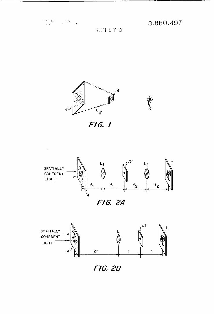
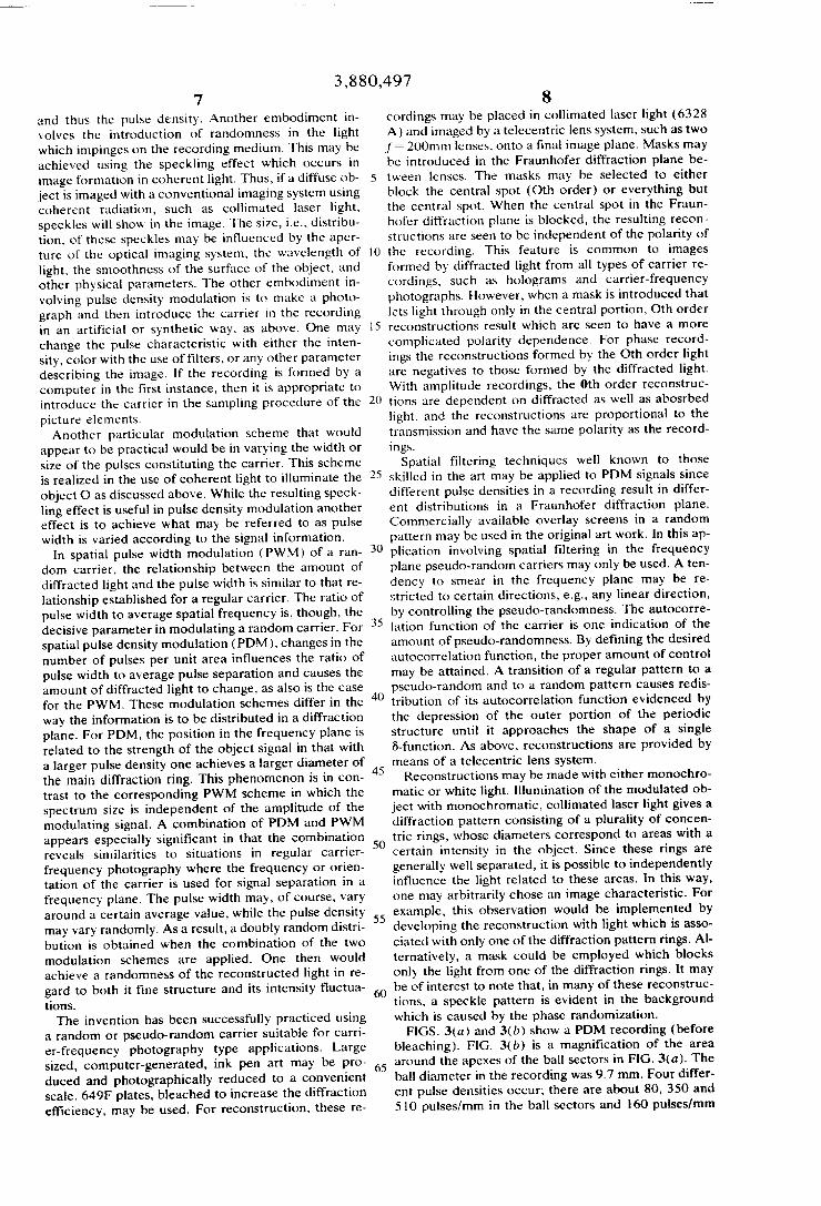
FIG. 1 is a schematic drawing of a recording of an ob ject illuminated with ambient light; FIGS. 2(a) and (b) are schematic drawings of recon
struction arrangements for imaging an object onto a re cording; FIGS. 3(a)—3(d) are an illustration of spatial pulse
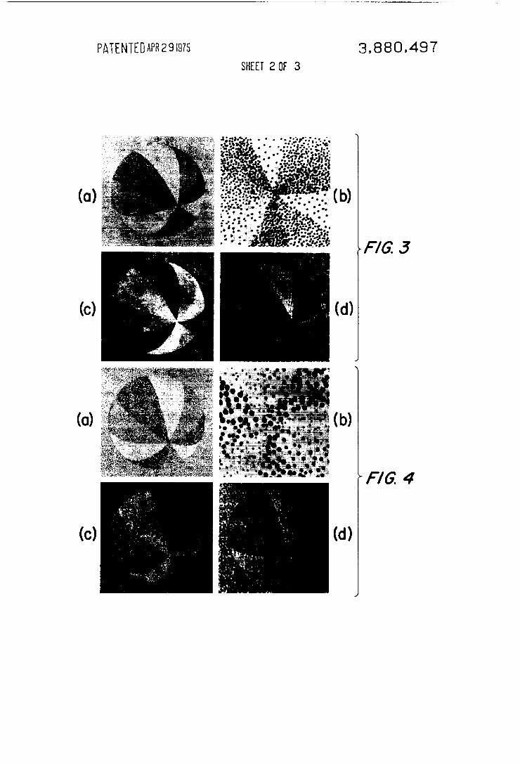
density modulation ofa random carrier, (a) the record ing, (b) a magni?ed portion ofthe recording, (0) recon structed image using scattered light; and (d) recon structed image using unscattered light. FIGS. 4(a)-4(d) are an illustration of spatial pulse
width modulation of a random carrier, (a) the record ing, (b) a magni?ed portion ofthe recording, (c) recon structed image using scattered light, and (d) recon structed image using unscattered light. FIGS. 5(a)-5(h) are an illustration of the recording
and reconstruction of a modulated flower.
DESCRIPTION OF THE PREFERRED EMBODIMENT
In FIG. 1 is shown an object O which is imaged onto a recording 4 by a camera housing 2 which has an aper ture 6. The object O is illuminated by ambient light. The recording 4 is a physical element which is respon sive to the light distribution from the original object 0, such as transparent emulsions or deformographic mate rial. In this embodiment the recording 4 is a photo graphic emulsion which is characterized by a pseudo random distribution of grains or pulses, which have a spatial variation on the order of the wavelength oflight. A suitable emulsion would be Kodak PLUS-X ?lm. When exposed to the light distribution from the ob
ject 0 through the aperture 6, the distribution of the grains is modi?ed or modulated in accordance with the intensity distribution from the object O. The higher the intensity the more grains or pulses are obtained in the recording 4. Such modulation which results in a density distribution of grains in relation to the intensity distri bution from the object O is to be referred to as pulse density modulation. By varying the size of the aperture 6, the intensity of the light on the recording 4 may be varied and, thereby, the modulation of the distribution of grains may be controlled. The distribution of grains in the recording 4 is a mi
crostructure which serves as a carrier for the storage of optical information from the object 0. When this mi crostructure is modulated by the intensity distribution from the object 0, it is thereby coded with intensity in formation. In conventional photography, it is not desir able to have grains of the size required in the present invention, since they would be disturbing elements in forming an image of the original object O on the photo graphic ?lm. In the present invention a microstructure of the object O is formed of resolvable elements in the recording 4. From such a recording, image processing or image reconstruction may be performed. Other pulse distributions, such as speckles, particles,
inhomogeneities and apertures, as well as other ele
l0
15
25
35
50
55
65
4 ments that in?uence a light wave, with a fairly random nature may be used as carriers. A suitable carrier may even be obtained by allowing the elements ofa periodic structure of a regular array to randomly deviate from their original positions. Several physical properties in herently form random or pseudo-random distributions, i.e., ?lm grain noise and natural wrinkling of phase media such as gelatin layers, thermoplastics, elastomers and other deformographic media. Therefore, these ma terials may serve as a suitable carrier in this preferred embodiment. A dot-pattem from a mask or screen may also be superimposed upon the object distribution to obtain a randomized distribution of pulses which would serve as a carrier. A recording of such a carrier could then be made on conventional ?lms which would not naturally have resolvable grains.
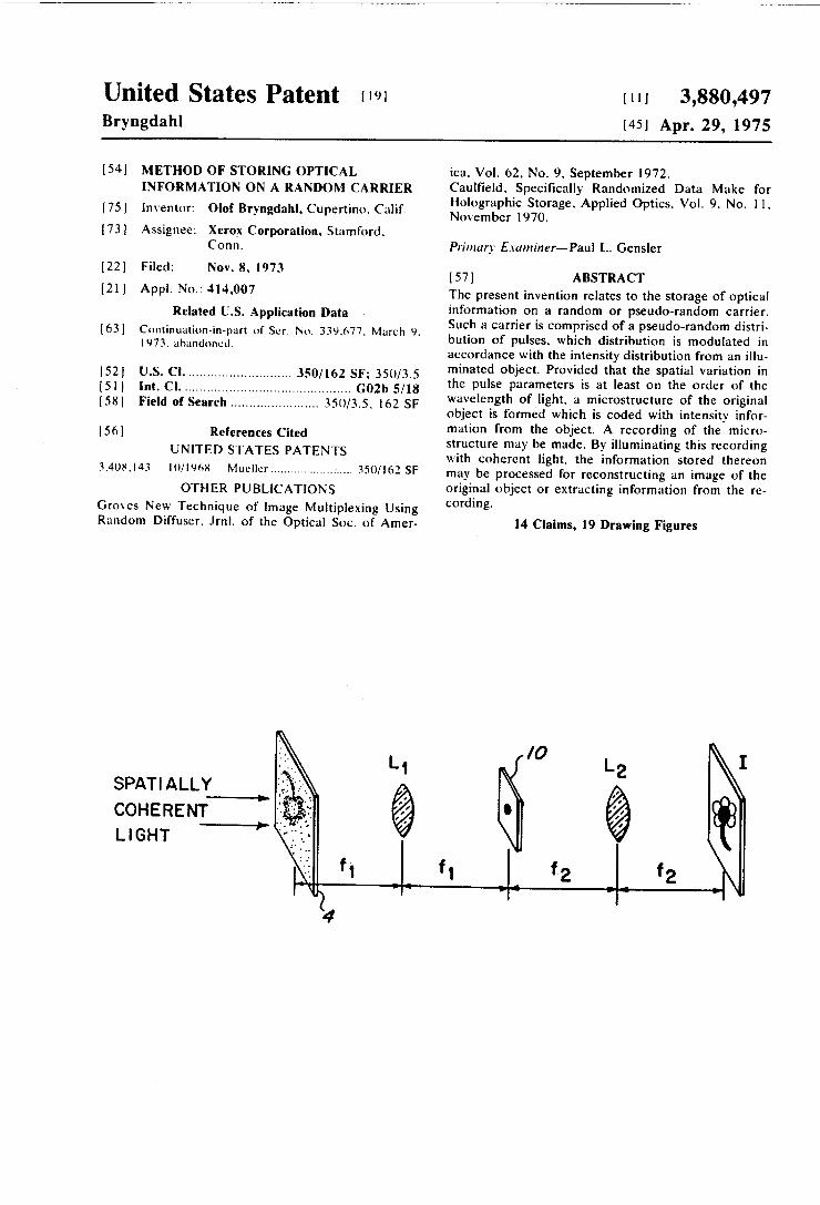
In order to reconstruct an image of the original ob ject O or to otherwise extract information from the re cording 4, the recording 4 is illuminated with spatially coherent light as shown in FIG. 2. As embodied in FIG. 2(a), two simple lenses LI and L2 having respective focal lengthsf, andf2 are positioned in the optical path between the recording 4 and the ?nal image plane I. In the Fraunhofer diffraction plane (frequency plane), at a distance fl from lens L, and a distance f2 from lens L2, an optical ?lter or stop 10 is located. The diffracted light from the recording 4 is imaged by
the lens L,, which performs a first Fourier transform of the distribution of pulses in the wavefront. In the fre quency plane is formed a Fourier spectrum. With the ?lter 10 we may block out portions of this light distri bution in the frequency plane to provide for optical processing or the reconstruction of an image of the original object in the ?nal image plane I. The un blocked light distribution in the frequency plane is im aged through the lens L2, which performs a second Fourier transform, to provide a reconstructed image in the image plane I.
In FIG. 2(b) is shown an alternative convolution of the element of FIG. 2(a) using a single lens to achieve image reconstruction. To provide a reconstructed image of the original ob
ject O in the plane I, without introducing optical pro cessing, a central stop would serve as the ?lter 10 in the diffraction or frequency plane. If optical processing is desired to enhance or modify the ?nal image, then spe ci?c ?lters may be introduced to achieve particular re sults. Such ?lter selection is taught by Goodman in In !roduction to Fourier Optics (McGraw-Hill, 1968).
In order to display the stored information or record ing, spatial ?ltering is thus used to extract object infor mation onto a ?nal image plane I by illuminating the recording 4 with spatially coherent light. In the inter mediate Fraunhofer diffraction plane undiffracted light is blocked revealing an isotropic spectrum which is in dependent of the direction in the Fraunhofer diffrac tion plane. This phenomenon renders the optical sys tem insensitive to otherwise disturbing moire-effects. While the above result of producing an isotropic
spectrum, which is characterized by a ring-structure, is unique as provided by the invention, previous experi ments by others have viewed similar frequency spec trums. For example, Exner in the late 1800‘s repeated the Fraunhofer’s experiment and called the structures in the diffraction pattern Fraunhofer‘s rings. Also, Debye and Scherrer in 1916 reported on the observa tion of a circular diffraction halo surrounding a central

3,880,497 5
portion when a liquid is illuminated with a narrow beam of X-rays. Similar patterns also occur from amor phous solids and imperfect crystals. The technique in volved in the last situation constitutes a convenient in— vestigative tool which has become standard is crystallo graphic analysis.
lt is assumed that. in all practical situations in which the invention is practiced, the shape of the spectrum would characterize a pseudo-random carrier. If the car rier constituted a periodic one-dimensional pattern, one may represent the distribution as a row of small ap ertures (E-functions ), regularly spaced with a given pe riod p, in a mask placed in collimated light. The pattern is to be modi?ed in order to introduce a random or pseudo-random distribution by achieving some degree of irregularity in the locations of the apertures. One technique which achieves the desired distribution is to displace the apertures to conform to a Gaussian distri bution around their true positions as is shown by Lip son and Lipson, Optical Physics (Cambridge University Press, Cambridge, 1969), Page 399. The autocorre lation of the resulting irregular pattern is a row of evenly spaced Gaussians, with the Gaussian at the ori gin being a (‘S-function. The irradiance distribution in the diffraction pattern of the randomly displaced aper tures is given by the Fourier transform of the autocor relation. This transform would be the transform of a periodic function of Gaussians subtracted and added by the transforms of the center Gaussian, and true-center ?-function. Thus, an irregularity of this kind will not de stroy the sharpness of the diffraction peaks. It will, on the other hand, add a background that is zero at the ori gin but increases with the distance from the origin of the diffraction pattern. Another approach to randomize the distribution is to
modify the location of the apertures so that the spacing between the closest neighbors are independent and vary around the average distance p, as would be taught by Guinier, X -Ray Diffraction in Crystals, Imperfect Crystals, and Amorphous Bodies (Freeman, San Fran cisco, 1963 ), Chapter 9.1. If the spacings all follow the same statistical distribution h(x), the distribution func tion for the distance between second neighbors is
h2(X) = 11(X) * Mr)
and in general
h,,(x) =h(x) * h(.r) * . . . * h(.r) (n times) (1)
and the average distance between the nth neighbors is np. The distribution around np will broaden with in creasing n; it will overlap the distribution around (n-l )p and (n+1 )p, and, ?nally, the total distribution will become uniform. The total distribution is
fix‘) = 8(x) + Z, anon + n=l
&
b (—X), 21 n (2) and its Fourier transform, as a function of frequency v, is
99w 2 2 2 1+2 2. exp (—2trn>l A)
n=l 1(9)
cos (ZiTIWP) i (3)
25
30
35
40
45
50
55
60
65
6 where A is the standard deviation of h(x); and for small values of Alp, the amount of the nth maxi mum of this curve is
E P‘Vl'rrn2 A2}- (4) The area under each pseudoperiod Up of the curve represented by Eq. (3) is constant (=l/p). For small n values, the width of the nth peak is proportional to
n2 A 2/p3.
For real objects where the transforms are two dimensional, the peaks become rings and the cosine in Eq. (3) will be replaced by a Zeroth order Bessel func tion. The widths of the rings increase with both A , which is the amount of randomness, and n; the irradi ance of the rings decrease with increasing A and n; complete randomness will result in a constant irradi ance in the frequency plane. Both of these ways of introducing irregularity among
the pulses constituting a pseudorandom carrier are fea sible. However, some of their characteristics, as shown above, are fundamentally different, and for specific ap plications, either one of the two types will be more suited or only one can be used. For example, only the second kind is possible in those cases where such a de gree of localization in the frequency plane is required that spatial ?ltering techniques are applicable. Of course, in addition to the two ways visualized above, there are numerous other possibilities for creating ir regular carriers with structured power spectra. As mentioned previously, the use of well-known spa
tial ?ltering techniques may be employed to provide for optical processing of the light distribution in the dif fraction plane. The present invention provides another mechanism
for processing an image of the original object in the ?nal image plane. By arti?cially randomizing the pseu do-random distribution of pulses which constitute the carrier, a micro-texture may be introduced in the ?nal image. This feature is important in that the micro texture in images eliminates the effects of a degraded optical system. Particularly in the use of coherent light such effects could otherwise be a disturbing in?uence in the reconstruction of images. One means of arti?cially randomizing the carrier is to
photograph objects, using the particular recording media disclosed herein including bleached photo graphic materials, through a randomized screen. In this way, after development, a microstructure of the object will be obtained in the recording 4 which, when opti cally processed as described above, will yield a mi crotexture in the ?nal image. The microtexture in the ?nal image is related to the microstructure in the re cording 4 by the Fourier transforms in the reconstruc tion process. Other means of arti?cially randomizing the carrier is by introducing speckle patterns by illumi nating the original object O with spatially coherent light. The speckle patterns serve as a randomized mi crostructure on the recording media which will pro duce a microtexture in the ?nal image.
In the illustrative embodiment a grainy recording me dium serves as the carrier. Formation of an image with a conventional camera onto this material will then, after development, result in a pulse density modulation (PDM) recording. With increasing light level, i.e., ex posure, the number of developed grains will increase
3,880,497 7
and thus the pulse density. Another embodiment in' volves the introduction of randomness in the light which impinges on the recording medium. This may be achieved using the speckling effect which occurs in image formation in coherent light. Thus, if a diffuse ob ject is imaged with a conventional imaging system using coherent radiation, such as collimated laser light, speckles will show in the image. The size, i.e., distribu tion, of these speckles may be in?uenced by the aper ture of the optical imaging system, the wavelength of light, the smoothness of the surface of the object, and other physical parameters. The other embodiment in volving pulse density modulation is to make a photo graph and then introduce the carrier in the recording in an artificial or synthetic way, as above. One may change the pulse characteristic with either the inten sity, color with the use of ?lters, or any other parameter describing the image. If the recording is formed by a computer in the first instance, then it is appropriate to introduce the carrier in the sampling procedure of the picture elements Another particular modulation scheme that would
appear to be practical would be in varying the width or size of the pulses constituting the carrier. This scheme is realized in the use of coherent light to illuminate the object O as discussed above. While the resulting speck ling effect is useful in pulse density modulation another effect is to achieve what may be referred to as pulse width is varied according to the signal information.
In spatial pulse width modulation (PWM) of a ran dom carrier, the relationship between the amount of diffracted light and the pulse width is similar to that re lationship established for a regular carrier. The ratio of pulse width to average spatial frequency is, though, the decisive parameter in modulating a random carrier. For ‘ spatial pulse density modulation (PDM), changes in the number of pulses per unit area in?uences the ratio of pulse width to average pulse separation and causes the amount of diffracted light to change, as also is the case for the PWMv These modulation schemes differ in the way the information is to be distributed in a diffraction plane. For PDM, the position in the frequency plane is related to the strength of the object signal in that with a larger pulse density one achieves a larger diameter of the main diffraction ring. This phenomenon is in con trast to the corresponding PWM scheme in which the spectrum size is independent of the amplitude of the modulating signal. A combination of PDM and PWM appears especially signi?cant in that the combination reveals similarities to situations in regular carrier frequency photography where the frequency or orien tation of the carrier is used for signal separation in a frequency plane. The pulse width may, of course, vary around a certain average value, while the pulse density may vary randomly. As a result, a doubly random distri bution is obtained when the combination of the two modulation schemes are applied. One then would achieve a randomness of the reconstructed light in re gard to both it fine structure and its intensity ?uctua tions. The invention has been successfully practiced using
a random or pseudo-random carrier suitable for carri er-frequency photography type applications. Large sized, computer-generated, ink pen art may be pro duced and photographically reduced to a convenient scale. 649F plates, bleached to increase the diffraction efficiency, may be used. For reconstruction, these re
20
30
40
55
65
8 cordings may be placed in collimated laser light (6328 A) and imaged by a telecentric lens system, such as two f: 200mm lenses, onto a ?nal image plane. Masks may be introduced in the Fraunhofer diffraction plane be tween lenses. The masks may be selected to either block the central spot (Oth order) or everything but the central spot. When the central spot in the Fraun hofer diffraction plane is blocked, the resulting recon structions are seen to be independent of the polarity of the recording. This feature is common to images formed by diffracted light from all types of carrier re cordings, such as holograms and carrier-frequency photographs. However, when a mask is introduced that lets light through only in the central portion, 0th order reconstructions result which are seen to have a more complicated polarity dependence. For phase record ings the reconstructions formed by the 0th order light are negatives to those formed by the diffracted light. With amplitude recordings, the 0th order reconstruc tions are dependent on diffracted as well as abosrbed light, and the reconstructions are proportional to the transmission and have the same polarity as the record ings.
Spatial ?ltering techniques well known to those skilled in the art may be applied to PDM signals since different pulse densities in a recording result in differ ent distributions in a Fraunhofer diffraction plane. Commercially available overlay screens in a random pattern may be used in the original art work. In this ap~ plication involving spatial filtering in the frequency plane pseudo~random carriers may only be used. A ten dency to smear in the frequency plane may be re stricted to certain directions, e.g., any linear direction, by controlling the pseudo-randomness. The autocorre lation function of the carrier is one indication of the amount of pseudo-randomness. By defining the desired autocorrelation function, the proper amount of control may be attained. A transition of a regular pattern to a pseudo-random and to a random pattern causes redis tribution of its autocorrelation function evidenced by the depression of the outer portion of the periodic structure until it approaches the shape of a single 6—function. As above, reconstructions are provided by means of a telecentric lens system. Reconstructions may be made with either monochro
matic or white light. Illumination of the modulated ob ject with monochromatic, collimated laser light gives a diffraction pattern consisting of a plurality of concen tric rings, whose diameters correspond to areas with a certain intensity in the object. Since these rings are generally well separated, it is possible to independently in?uence the light related to these areas. In this way, one may arbitrarily chose an image characteristic. For example, this observation would be implemented by developing the reconstruction with light which is asso ciated with only one of the diffraction pattern rings. Al ternatively, a mask could be employed which blocks only the light from one of the diffraction rings. It may be of interest to note that, in many of these reconstruc tions, a speckle pattern is evident in the background which is caused by the phase randomization. FIGS. 3(a) and 3(b) show a PDM recording (before
bleaching). FIG. 3(b) is a magni?cation of the area around the apexes of the ball sectors in FIG. 3(a). The ball diameter in the recording was 9.7 mm. Four differ ent pulse densities occur; there are about 80, 350 and 510 pulses/mm in the ball sectors and I60 pulses/mm
3,880,497 9
in the background. The pulses all have a diameter of about ltw’ um and were placed at random; the only rc striction was to avoid overlapping. 'l’he reconstructions are shown in HUS. Mr) and Mil)‘, l"l(i. 3(0) results when a central stop is introduced in the l‘raunhofen diffraction plane and FIG. Jul) when a mask is intro duced that lets light through only in the central portion.
l-‘l(i. 4 illustrates the results with PWM. The ball di ameter here is also 9.7 mm. There are about I It) pul ses/mm in all areas. However, the pulse diameter va ries: [8, 3b, and (i2 pan in the ball sectors and 27 pm in the background. The reconstructions shown in FIGS. 3((1 and 4h‘)
are independent of the polarity of the recording. This is a feature common to images formed by diffracted light from all types of carrier recordings. such as holo grams and carrier»frequency photographs. The 0th order reconstructions. on the other hand, have a more eomplicatcd polarity dependence. For phase record ings (see FIGS. 3(4!) and 4(1Il), the reconstructions formed by ()th-order llth-order light are negatives to those formed by the diffracted light. With amplitude recordings. the ()th—order reconstructions are depen dent on diffracted as well as absorbed light, and the re constructions will have the same polarity (proportional to the transmittance) as the recordings.
lllumination of a random pulse pattern with white light results in a spectrum decomposition of the dif fracted ring with the blue end of the spectrum closest to the Oth order. The spectrum rings may he separated suf?ciently to allow reconstruction of an object in color. Reconstruction in color would be possible by using a spatial ?lter dimensioned to transmit a wanted portion of the colors in the spectrum rings. In one suc cessful application, the diffraction pattern of the modu lated object was constructed of light from a xenon are which consisted of three spectrum rings. Any color combinations between those inden?ying the object were possible by using a spatial ?lter in the shape of three transparent rings to match the three spectrum rings. Shown in FIG. 5 is the diffraction pattern of the modulated flower in white light from a xenon are which consisted ofthree spectrum rings. In FIG. 5(a) is shown the recording, (h) its Fraunhofer-diffraction pattern, (0) the carrier in the center of the ?ower, (d) diffrac tion pattern of (c), (1') the carrier in the petals, (I) dif fraction pattern of (r), (g) the carrier in the back ground, and (h) diffraction pattern of (g). When using white light for image reconstruction
from random carrier photographs, identifying features occur on a microscopic scale. The spectral ring shaped diffraction patterns show characteristic radial streaks. Furthermore, random color inhomogeneities or dot patterns are observable in solid areas of the image when the dimensions of the spatial ?lter are decreased. At the same time. the purity of the colors increases.
In addition to PDM and PWM, other modulation schemes may be used in modulating a random carrier. These would include pulse amplitude modulation (PAM), pulse position modulation (PPM), pulse fre quency modulation (PFM) and pulse code modulation (PCM). PAM, in particular, would be easily applicable in combination with conventional photography. Pseudo-randomness may be introduced in even more
ways. For example, a regular carrier may be converted to a pseudo‘random one by bending the periodic pat tern on a macro- or micro-scale, by local stretching, by
25
35
40
45
v
65
l 0 local rotation, or by any combination thereof. Diffrac tion patterns of crystallized material with irregularities display similarities to the pseudo-random carrier phe nomenon. An examination of the transforms of large numbers of different arrangements of representations of real and hypothetical chemical structures would allow additional implementations in accordance with the invention. In the case of applications in which spa tial ?ltering would be desired, the extension and shape of the power spectrum of the carrier, as well as the image micro texture, should be considered. Objects with periodic structures cause distrubing
moire effects when a regular carrier is used. A random or pseudo-random carrier serves to eliminate or reduce these phenomena. A comparison could be made be tween a regular two-dimensional spatial pulse carrier and a pseudo-random carrier with a one-dimensional grating structure with monotonically increasing fre quency superimposed on the respective carriers in order to demonstrate this result. In the latter case, the existence of any moire fringes would be lacking. Random and pseudo-random carriers are useful for
the same and similar applications as regular carriers. More speci?cally, the invention provides a valuable tool for storing optical information in phase-only re cording media. The random carriers utilized in accor dance with the invention possess capabilities for multi» plcxing and interlacing which are valuable features in optical storage, image display, and spatial ?ltering ap plications. Most signi?cant, is the ability to control image characteristics and color in the reconstructed images from black and white or phase recordings. The feature of controllable phase randomization is ex tremely advantageous in display and projection appli cations. Some physical processes are even inherent in random or pseudo-random distributions, e.g., ?lm grain noise and natural wrinkling of phase media such as gel atine layers, thermoplastics, elastomers, and other deformographic media. The random carrier features in accordance with the
invention may even be employed in combination with the random physical features characteristic of the re cording material. A more sophisticated way of control ling the random carrier features alone or in combina tion with random physical features is to introduce com puter-generated carriers resulting from the application of programs which practice the invention. Obviously, many modi?cations of the present invention are possi ble in light of this teaching. It is therefore to be under stood that, in the scope of the appended claims, the in vention may be practiced other than as speci?cally de scribed. What is claimed is: l. A method of storing optical information on a ran
dom carrier comprising the steps of: providing a carrier comprised of a pseudo-random distribution of pulses,
the spatial variation in the pulse parameters being at least equal to the wavelength of light;
modulating said distribution of pulses with optical in formation characterizing physical parameters of an illuminated object such that a microstructure is formed of a modi?ed distribution of pulses with the optical information coded thereon; and
recording the microstructure on a storage medium.
3,880,497 11
2. The method of claim 1 wherein is further included the step of reconstructing said optical information from said microstructure.
3. The method of claim 1 wherein the storage me dium is of an optically sensitive material which pro vides a carrier comprised of optical pulses in a pseudo random distribution coded with optical information from the object.
4. The method of claim 3 wherein is further included the step of reconstructing an image of the object from the microstructure defined by said distribution of opti cal pulses. I
S. The method of claim 4 wherein said reconstructing step includes the steps of illuminating said microstruc ture with spatially coherent light and imaging the re sulting diffracted irradiance onto an image plane.
6. The method of claim 5 wherein is further included the step of spatially ?ltering said irradiance between said microstructure and said image plane.
7. The method of claim 6 wherein said distribution of pulses is randomized such that a microtexture is pro vided in the image formed in said image plane.
8. The method of claim 7 wherein said irradiance is imaged by a telecentric lens system whereby a double
.... Ln
20
25
35
45
50
55
65
12 Fourier transform of the diffracted irradiance recon structs the image in said image plane.
9. The method of claim 3 wherein the storage me dium is a photographic emulsion which provides a car rier comprised of a distribution of grains.
10. The method of claim 3 wherein the storage me dium is of deformagraphic material which provides a carrier comprised of a distribution of wrinkles.
11. The method of claim I wherein the number of pulses in said distribution is modulated in accordance with the intensity of said optical information.
12. The method of claim I wherein the width of pulses in said distribution is modulated in accordance with the intensity of said optical information.
13. The method of claim 1 wherein the number and width of pulses in said distribution is modulated in ac cordance with the intensity of said optical information.
14. The method of claim 11 wherein said distribution is a distribution of optical pulses coded with optical in formation and wherein is further included the step of reconstructing said optical information from said distri bution whereby a randomness of reconstructed light in regard to both density and intensity is achieved‘
* >l= * * *