fxmq-pbvju ceiling mounted duct type · 2018-02-12 · features and benefits edus391503-f4 2...
TRANSCRIPT

FXMQ-PBVJU
Ceiling Mounted Duct Type
EDUS391503-F4

EDUS391503-F4
FXMQ-PBVJU 1
FXMQ-PBVJUCeiling Mounted Duct Type
1. Features and Benefits .................................................................................22. Specifications ..............................................................................................33. Dimensions .................................................................................................64. Piping Diagrams........................................................................................115. Wiring Diagrams........................................................................................126. Electric Characteristics..............................................................................137. Safety Devices Setting ..............................................................................148. Capacity Tables ........................................................................................15
8.1 Cooling Capacity at Te: 43°F (6°C) ............................................................ 158.2 Heating Capacity ........................................................................................ 158.3 Correction Factor for Cooling Capacity at Te: 48°F (9°C) .......................... 16
9. Fan Performance ......................................................................................1710.Airflow Auto Adjustment Characteristics ...................................................2611.Sound Levels (Reference Data)................................................................3412.Center of Gravity .......................................................................................4213.Accessories...............................................................................................43
13.1 Optional Accessories (For Controls) .......................................................... 43
14.Auxiliary Electric Heater Setting................................................................44
Appendix .......................................................................................................... i1. Installation Manual ......................................................................................1

Features and Benefits EDUS391503-F4
1. Features and BenefitsThe ceiling mounted DC Ducted unit is ideal for small to large spaces in need of a concealed air-conditioning system. Its compact design allows it to be completely concealed and makes it perfect for retail stores, classrooms, offices, banks, restaurants, shops and hotels.
Models range from 0.6 up to 4.5 TonEnergy efficient thanks to the specially developed DC fan motor Ideal to use together with the optional Daikin Zoning Kit, DZKConfigurable auxiliary heater control logicAdvanced economizer control logic Enhanced indoor air quality and LEED ready with MERV 13 filter options Ease of installation with auto adjusting airflow at commissioning based on external static pressureFlexible ductwork design with ESP capabilities up to 0.8" W.G.Installation flexibility with a low profile, compact design at less than 12" in heightEasy maintenance with complete service access from belowStandard built-in drain pump increases flexibility and installation speed
2 FXMQ-PBVJU

EDUS391503-F4 Specifications
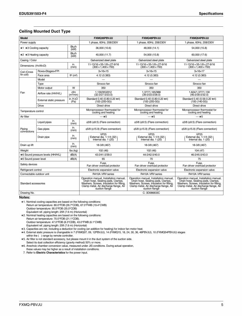
2. Specifications
Ceiling Mounted Duct Type
Notes:1. Nominal cooling capacities are based on the following conditions:
Return air temperature: 80.0°FDB (26.7°CDB), 67.0°FWB (19.4°CWB)Outdoor temperature: 95.0°FDB (35.0°CDB)Equivalent ref. piping length: 25ft (7.6 m) (Horizontal)
2. Nominal heating capacities are based on the following conditions:Return air temperature: 70.0°FDB (21.1°CDB).Outdoor temperature: 47.0°FDB (8.3°CDB), 43.0°FWB (6.1°CWB)Equivalent ref. piping length: 25ft (7.6 m) (Horizontal)
3. Capacities are net, including a deduction for cooling (an addition for heating) for indoor fan motor heat.4. External static pressure is changeable in 7 (FXMQ07, 09, 12PBVJU), 14 (FXMQ15, 18, 24, 30, 36, 48PBVJU), 10 (FXMQ54PBVJU) stages
within the ( ) range by remote controller.5. Air filter is not standard accessory, but please mount it in the duct system of the suction side.
Select its dust collection efficiency (gravity method) 50% or more.6. Anechoic chamber conversion value, measured under JIS conditions. During actual operation,
these values may be higher as a result of installation conditions.7. Refer to Electric Characteristics for the power input.
Model FXMQ07PBVJU FXMQ09PBVJU FXMQ12PBVJU FXMQ15PBVJU
Power supply 1 phase, 60Hz, 208/230V 1 phase, 60Hz, 208/230V 1 phase, 60Hz, 208/230V 1 phase, 60Hz, 208/230V
1 3 Cooling capacity Btu/h (kW) 7,500 (2.2) 9,500 (2.8) 12,000 (3.5) 15,000 (4.4)
2 3 Heating capacity Btu/h (kW) 8,500 (2.5) 10,500 (3.1) 13,500 (4.0) 17,000 (5.0)
Casing / Color Galvanized steel plate Galvanized steel plate Galvanized steel plate Galvanized steel plate
Dimensions: (H×W×D) in. (mm)
11-13/16 × 21-5/8 × 27-9/16(300 × 550 × 700)
11-13/16 × 21-5/8 × 27-9/16(300 × 550 × 700)
11-13/16 × 27-9/16 × 27-9/16(300 × 700 × 700)
11-13/16 × 39-3/8 × 27-9/16(300 × 1,000 × 700)
Coil (Cross fin coil)
Rows×Stages×FPI 3×16×15 3×16×15 3×16×15 3×16×15
Face area ft² (m²) 1.05 (0.098) 1.05 (0.098) 1.59 (0.148) 2.68 (0.249)
Fan
Model — — — —
Type Sirocco fan Sirocco fan Sirocco fan Sirocco fan
Motor output W 90 90 140 350
Airflow rate (HH/H/L) cfm(m³/min)
317/264/229(9.0/7.5/6.5)
317/264/229(9.0/7.5/6.5)
450/410/388(12.7/11.6/11.0)
560/530/500(15.8/15.0/14.2)
External static pressure in. H 2O (Pa)
Standard 0.20 (0.40-0.12 4)(50 (100-30))
Standard 0.20 (0.40-0.12 4)(50 (100-30))
Standard 0.20 (0.40-0.12 4)(50 (100-30))
Standard 0.40 (0.80-0.20 4)(100 (200-50))
Drive Direct drive Direct drive Direct drive Direct drive
Temperature control Microprocessor thermostat for cooling and heating
Microprocessor thermostat for cooling and heating
Microprocessor thermostat for cooling and heating
Microprocessor thermostat for cooling and heating
Air filter — 5 — 5 — 5 — 5
Piping connections
Liquid pipes in. (mm)
φ1/4 (φ6.4)(Flare connection)
φ1/4 (φ6.4)(Flare connection)
φ1/4 (φ6.4)(Flare connection)
φ1/4 (φ6.4)(Flare connection)
Gas pipes in. (mm)
φ1/2 (φ12.7)(Flare connection)
φ1/2 (φ12.7)(Flare connection)
φ1/2 (φ12.7)(Flare connection)
φ1/2 (φ12.7)(Flare connection)
Drain pipe in. (mm)
VP25External dia. 1-1/4 (32)
Internal dia. 1 (25)
VP25External dia. 1-1/4 (32)
Internal dia. 1 (25)
VP25External dia. 1-1/4 (32)
Internal dia. 1 (25)
VP25External dia. 1-1/4 (32)
Internal dia. 1 (25)
Drain up lift in. (mm) 18-3/8 (467) 18-3/8 (467) 18-3/8 (467) 18-3/8 (467)
Weight lbs (kg) 55 (25) 55 (25) 62 (28) 80 (36)
6 Sound pressure levels (HH/H/L) dB(A) 33.0/31.0/29.0 33.0/31.0/29.0 39.0/37.0/35.0 40.0/38.0/37.0
6 Sound power level dB(A) 56 56 65 61
Safety devices Fuse,Fan driver overload protector
Fuse,Fan driver overload protector
Fuse,Fan driver overload protector
Fuse,Fan driver overload protector
Refrigerant control Electronic expansion valve Electronic expansion valve Electronic expansion valve Electronic expansion valve
Connectable outdoor unit R410A VRV series R410A VRV series R410A VRV series R410A VRV series
Standard accessories
Operation manual, Installation manual, Drain
hose, Sealing pads, Clamps, Washers, Screws, Insulation for fitting, Clamp metal, Air
discharge flange, Air suction flange
Operation manual, Installation manual, Drain
hose, Sealing pads, Clamps, Washers, Screws, Insulation for fitting, Clamp metal, Air
discharge flange, Air suction flange
Operation manual, Installation manual, Drain
hose, Sealing pads, Clamps, Washers, Screws, Insulation for fitting, Clamp metal, Air
discharge flange, Air suction flange
Operation manual, Installation manual, Drain
hose, Sealing pads, Clamps, Washers, Screws, Insulation for fitting, Clamp metal, Air
discharge flange, Air suction flange
Drawing No. C: 3D086833C
( ) ( ) ( ) ( )
FXMQ-PBVJU 3

Specifications EDUS391503-F4
Ceiling Mounted Duct Type
Notes:1. Nominal cooling capacities are based on the following conditions:
Return air temperature: 80.0°FDB (26.7°CDB), 67.0°FWB (19.4°CWB)Outdoor temperature: 95.0°FDB (35.0°CDB)Equivalent ref. piping length: 25ft (7.6 m) (Horizontal)
2. Nominal heating capacities are based on the following conditions:Return air temperature: 70.0°FDB (21.1°CDB).Outdoor temperature: 47.0°FDB (8.3°CDB), 43.0°FWB (6.1°CWB)Equivalent ref. piping length: 25ft (7.6 m) (Horizontal)
3. Capacities are net, including a deduction for cooling (an addition for heating) for indoor fan motor heat.4. External static pressure is changeable in 7 (FXMQ07, 09, 12PBVJU), 14 (FXMQ15, 18, 24, 30, 36, 48PBVJU), 10 (FXMQ54PBVJU) stages
within the ( ) range by remote controller.5. Air filter is not standard accessory, but please mount it in the duct system of the suction side.
Select its dust collection efficiency (gravity method) 50% or more.6. Anechoic chamber conversion value, measured under JIS conditions. During actual operation,
these values may be higher as a result of installation conditions.7. Refer to Electric Characteristics for the power input.
Model FXMQ18PBVJU FXMQ24PBVJU FXMQ30PBVJU
Power supply 1 phase, 60Hz, 208/230V 1 phase, 60Hz, 208/230V 1 phase, 60Hz, 208/230V
1 3 Cooling capacity Btu/h (kW) 18,000 (5.3) 24,000 (7.0) 30,000 (8.8)
2 3 Heating capacity Btu/h (kW) 20,000 (5.9) 27,000 (7.9) 34,000 (10.0)
Casing / Color Galvanized steel plate Galvanized steel plate Galvanized steel plate
Dimensions: (H×W×D) in. (mm)
11-13/16 × 39-3/8 × 27-9/16(300 × 1,000 × 700)
11-13/16 × 39-3/8 × 27-9/16(300 × 1,000 × 700)
11-13/16 × 55-1/8 × 27-9/16(300 × 1,400 × 700)
Coil (Cross fin coil)
Rows×Stages×FPI 3×16×15 3×16×15 3×16×15
Face area ft² (m²) 2.68 (0.249) 2.68 (0.249) 4.12 (0.383)
Fan
Model — — —
Type Sirocco fan Sirocco fan Sirocco fan
Motor output W 350 350 350
Airflow rate (HH/H/L) cfm(m³/min)
635/582/529(18.0/16.5/15.0)
688/618/565 (19.5/17.5/16.0)
1,094/953/812 (31.0/27.0/23.0)
External static pressure in. H 2O (Pa)
Standard 0.40 (0.80-0.20 4)(100 (200-50))
Standard 0.40 (0.80-0.20 4)(100 (200-50))
Standard 0.40 (0.80-0.20 4)(100 (200-50))
Drive Direct drive Direct drive Direct drive
Temperature control Microprocessor thermostat for cooling and heating
Microprocessor thermostat for cooling and heating
Microprocessor thermostat for cooling and heating
Air filter — 5 — 5 — 5
Piping connections
Liquid pipes in. (mm) φ1/4 (φ6.4) (Flare connection) φ3/8 (φ9.5) (Flare connection) φ3/8 (φ9.5) (Flare connection)
Gas pipes in. (mm) φ1/2 (φ12.7) (Flare connection) φ5/8 (φ15.9) (Flare connection) φ5/8 (φ15.9) (Flare connection)
Drain pipe in. (mm)
VP25External dia. 1-1/4 (32)
Internal dia. 1 (25)
VP25External dia. 1-1/4 (32)
Internal dia. 1 (25)
VP25External dia. 1-1/4 (32)
Internal dia. 1 (25)
Drain up lift in. (mm) 18-3/8 (467) 18-3/8 (467) 18-3/8 (467)
Weight lbs (kg) 80 (36) 80 (36) 102 (46)
6 Sound pressure levels (HH/H/L) dB(A) 41.0/39.0/37.0 42.0/40.0/38.0 43.0/41.0/39.0
6 Sound power level dB(A) 61 64 65
Safety devices Fuse,Fan driver overload protector
Fuse,Fan driver overload protector
Fuse,Fan driver overload protector
Refrigerant control Electronic expansion valve Electronic expansion valve Electronic expansion valve
Connectable outdoor unit R410A VRV series R410A VRV series R410A VRV series
Standard accessories
Operation manual, Installation manual, Drain hose, Sealing pads, Clamps,
Washers, Screws, Insulation for fitting, Clamp metal, Air discharge flange, Air
suction flange
Operation manual, Installation manual, Drain hose, Sealing pads, Clamps,
Washers, Screws, Insulation for fitting, Clamp metal, Air discharge flange, Air
suction flange
Operation manual, Installation manual, Drain hose, Sealing pads, Clamps,
Washers, Screws, Insulation for fitting, Clamp metal, Air discharge flange, Air
suction flange
Drawing No. C: 3D086833C
( ) ( ) ( )
4 FXMQ-PBVJU
EDUS391503-F4 Specifications
Ceiling Mounted Duct Type
Notes:1. Nominal cooling capacities are based on the following conditions:
Return air temperature: 80.0°FDB (26.7°CDB), 67.0°FWB (19.4°CWB)Outdoor temperature: 95.0°FDB (35.0°CDB)Equivalent ref. piping length: 25ft (7.6 m) (Horizontal)
2. Nominal heating capacities are based on the following conditions:Return air temperature: 70.0°FDB (21.1°CDB).Outdoor temperature: 47.0°FDB (8.3°CDB), 43.0°FWB (6.1°CWB)Equivalent ref. piping length: 25ft (7.6 m) (Horizontal)
3. Capacities are net, including a deduction for cooling (an addition for heating) for indoor fan motor heat.4. External static pressure is changeable in 7 (FXMQ07, 09, 12PBVJU), 14 (FXMQ15, 18, 24, 30, 36, 48PBVJU), 10 (FXMQ54PBVJU) stages
within the ( ) range by remote controller.5. Air filter is not standard accessory, but please mount it in the duct system of the suction side.
Select its dust collection efficiency (gravity method) 50% or more.6. Anechoic chamber conversion value, measured under JIS conditions. During actual operation,
these values may be higher as a result of installation conditions.7. Refer to Electric Characteristics for the power input.
Model FXMQ36PBVJU FXMQ48PBVJU FXMQ54PBVJU
Power supply 1 phase, 60Hz, 208/230V 1 phase, 60Hz, 208/230V 1 phase, 60Hz, 208/230V
1 3 Cooling capacity Btu/h (kW) 36,000 (10.6) 48,000 (14.1) 54,000 (15.8)
2 3 Heating capacity Btu/h (kW) 40,000 (11.7) 54,000 (15.8) 60,000 (17.6)
Casing / Color Galvanized steel plate Galvanized steel plate Galvanized steel plate
Dimensions: (H×W×D) in. (mm)
11-13/16 × 55-1/8 × 27-9/16(300 × 1,400 × 700)
11-13/16 × 55-1/8 × 27-9/16(300 × 1,400 × 700)
11-13/16 × 55-1/8 × 27-9/16(300 × 1,400 × 700)
Coil (Cross fin coil)
Rows×Stages×FPI 3×16×15 3×16×15 3×16×17
Face area ft² (m²) 4.12 (0.383) 4.12 (0.383) 4.12 (0.383)
Fan
Model — — —
Type Sirocco fan Sirocco fan Sirocco fan
Motor output W 350 350 350
Airflow rate (HH/H/L) cfm(m³/min)
1,130/953/812(32.0/27.0/23.0)
1,377/1,165/988(39.0/33.0/28.0)
1,624/1,377/1,130(46.0/39.0/32.0)
External static pressure in. H 2O (Pa)
Standard 0.40 (0.80-0.20 4)(100 (200-50))
Standard 0.40 (0.80-0.20 4)(100 (200-50))
Standard 0.40 (0.56-0.20 4)(100 (140-50))
Drive Direct drive Direct drive Direct drive
Temperature control Microprocessor thermostat for cooling and heating
Microprocessor thermostat for cooling and heating
Microprocessor thermostat for cooling and heating
Air filter — 5 — 5 — 5
Piping connections
Liquid pipes in. (mm) φ3/8 (φ9.5) (Flare connection) φ3/8 (φ9.5) (Flare connection) φ3/8 (φ9.5) (Flare connection)
Gas pipes in. (mm) φ5/8 (φ15.9) (Flare connection) φ5/8 (φ15.9) (Flare connection) φ5/8 (φ15.9) (Flare connection)
Drain pipe in. (mm)
VP25External dia. 1-1/4 (32)
Internal dia. 1 (25)
VP25External dia. 1-1/4 (32)
Internal dia. 1 (25)
VP25External dia. 1-1/4 (32)
Internal dia. 1 (25)
Drain up lift in. (mm) 18-3/8 (467) 18-3/8 (467) 18-3/8 (467)
Weight lbs (kg) 102 (46) 102 (46) 104 (47)
6 Sound pressure levels (HH/H/L) dB(A) 43.0/41.0/39.0 44.0/42.0/40.0 46.0/45.0/43.0
6 Sound power level dB(A) 65 70 75
Safety devices Fuse,Fan driver overload protector
Fuse,Fan driver overload protector
Fuse,Fan driver overload protector
Refrigerant control Electronic expansion valve Electronic expansion valve Electronic expansion valve
Connectable outdoor unit R410A VRV series R410A VRV series R410A VRV series
Standard accessories
Operation manual, Installation manual, Drain hose, Sealing pads, Clamps,
Washers, Screws, Insulation for fitting, Clamp metal, Air discharge flange, Air
suction flange
Operation manual, Installation manual, Drain hose, Sealing pads, Clamps,
Washers, Screws, Insulation for fitting, Clamp metal, Air discharge flange, Air
suction flange
Operation manual, Installation manual, Drain hose, Sealing pads, Clamps,
Washers, Screws, Insulation for fitting, Clamp metal, Air discharge flange, Air
suction flange
Drawing No. C: 3D086833C
( ) ( ) ( )
FXMQ-PBVJU 5

Dimensions EDUS391503-F4
3. Dimensions
FXMQ07PBVJU / FXMQ09PBVJU
3D06
5976
F
6 FXMQ-PBVJU

EDUS391503-F4 Dimensions
FXMQ12PBVJU
3D08
6927
C
FXMQ-PBVJU 7

Dimensions EDUS391503-F4
FXMQ15PBVJU / FXMQ18PBVJU
3D06
5977
E
8 FXMQ-PBVJU

EDUS391503-F4 Dimensions
FXMQ24PBVJU
3D06
5978
E
FXMQ-PBVJU 9

Dimensions EDUS391503-F4
FXMQ30PBVJU / FXMQ36PBVJU / FXMQ48PBVJU / FXMQ54PBVJU
3D06
5979
G
10 FXMQ-PBVJU

EDUS391503-F4 Piping Diagrams
4. Piping Diagrams
FXMQ07PBVJU / FXMQ09PBVJU / FXMQ12PBVJU / FXMQ15PBVJU / FXMQ18PBVJU / FXMQ24PBVJU / FXMQ30PBVJU / FXMQ36PBVJU / FXMQ48PBVJU / FXMQ54PBVJU
Unit: in. (mm)
Model Gas Liquid
FXMQ07PBVJUFXMQ09PBVJUFXMQ12PBVJUFXMQ15PBVJUFXMQ18PBVJU
φ 1/2(φ 12.7)
φ 1/4(φ 6.4)
FXMQ24PBVJUFXMQ30PBVJUFXMQ36PBVJUFXMQ48PBVJUFXMQ54PBVJU
φ 5/8(φ 15.9)
φ 3/8(φ 9.5)
C: 4D034245L
FXMQ-PBVJU 11
Wiring Diagrams EDUS391503-F4
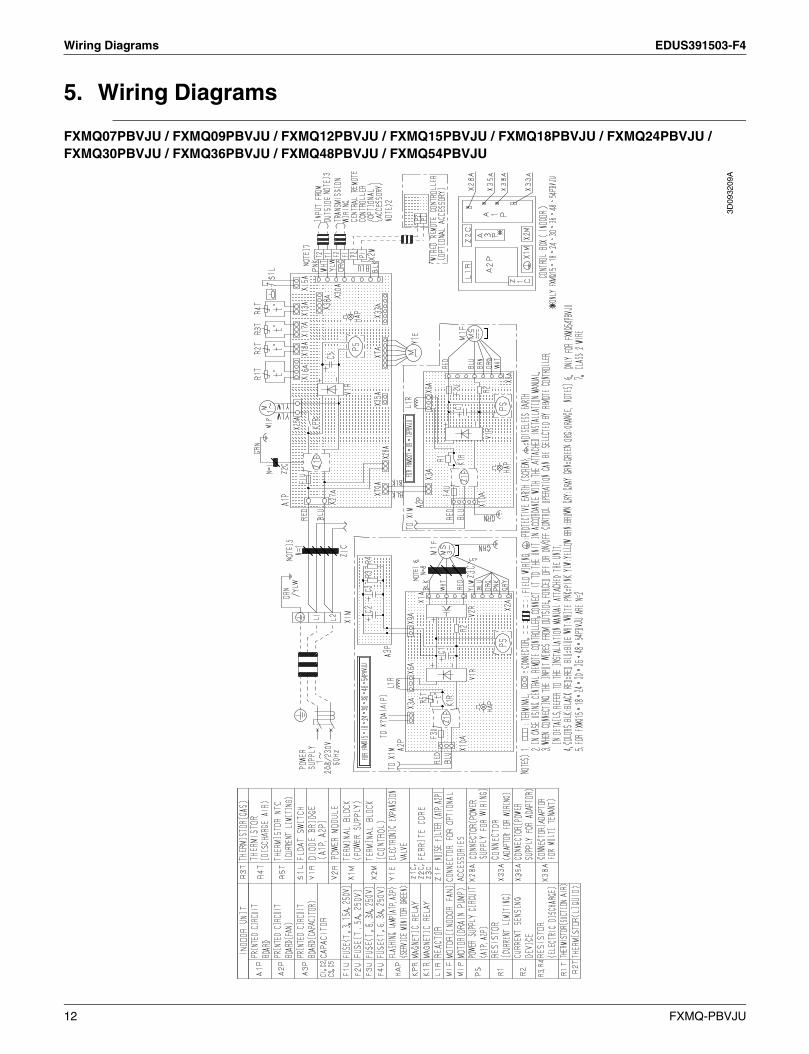
5. Wiring Diagrams
FXMQ07PBVJU / FXMQ09PBVJU / FXMQ12PBVJU / FXMQ15PBVJU / FXMQ18PBVJU / FXMQ24PBVJU / FXMQ30PBVJU / FXMQ36PBVJU / FXMQ48PBVJU / FXMQ54PBVJU
3D09
3209
A
12 FXMQ-PBVJU

EDUS391503-F4 Electric Characteristics
6. Electric Characteristics
FXMQ07PBVJU / FXMQ09PBVJU / FXMQ12PBVJU / FXMQ15PBVJU / FXMQ18PBVJU / FXMQ24PBVJU / FXMQ30PBVJU / FXMQ36PBVJU / FXMQ48PBVJU / FXMQ54PBVJU
C: 4D086914B
FXMQ-PBVJU 13
Safety Devices Setting EDUS391503-F4
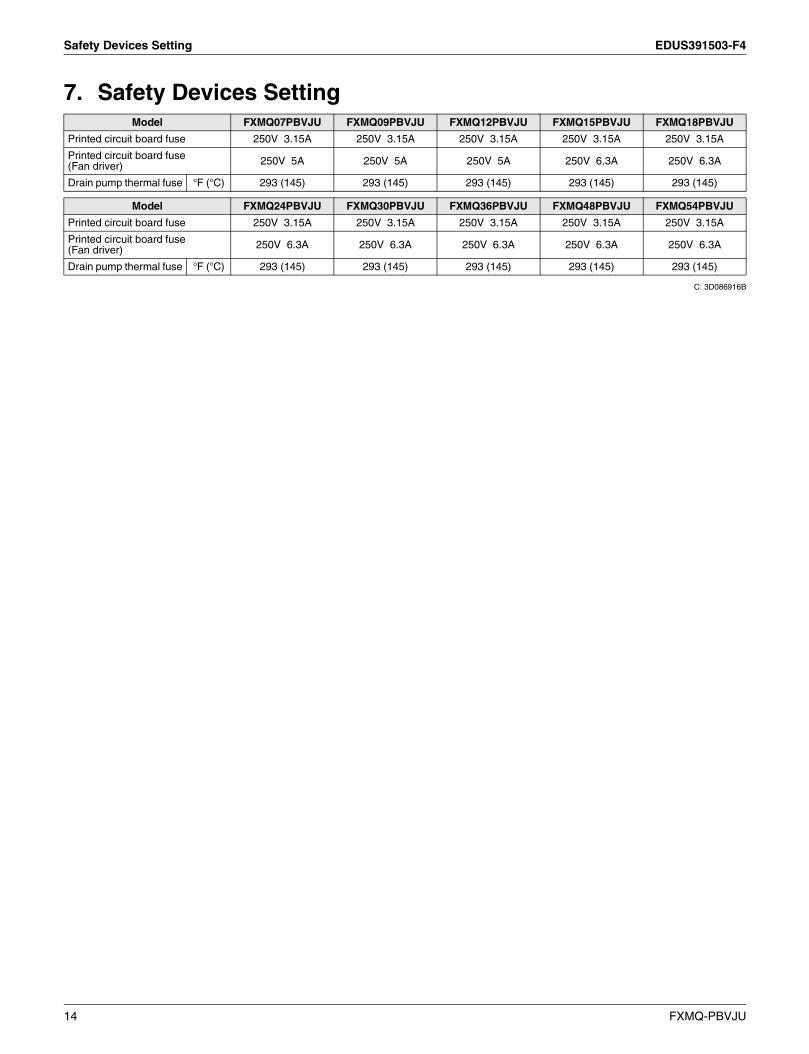
7. Safety Devices Setting
C: 3D086916B
Model FXMQ07PBVJU FXMQ09PBVJU FXMQ12PBVJU FXMQ15PBVJU FXMQ18PBVJU
Printed circuit board fuse 250V 3.15A 250V 3.15A 250V 3.15A 250V 3.15A 250V 3.15A
Printed circuit board fuse(Fan driver) 250V 5A 250V 5A 250V 5A 250V 6.3A 250V 6.3A
Drain pump thermal fuse °F (°C) 293 (145) 293 (145) 293 (145) 293 (145) 293 (145)
Model FXMQ24PBVJU FXMQ30PBVJU FXMQ36PBVJU FXMQ48PBVJU FXMQ54PBVJU
Printed circuit board fuse 250V 3.15A 250V 3.15A 250V 3.15A 250V 3.15A 250V 3.15A
Printed circuit board fuse(Fan driver) 250V 6.3A 250V 6.3A 250V 6.3A 250V 6.3A 250V 6.3A
Drain pump thermal fuse °F (°C) 293 (145) 293 (145) 293 (145) 293 (145) 293 (145)
14 FXMQ-PBVJU

EDUS391503-F4 Capacity Tables
8. Capacity Tables8.1 Cooling Capacity at Te: 43°F (6°C)
8.2 Heating Capacity
Model
Indoor air temp. °FWB (Te: 43°F (6°C))
61 64 67 70 72 75
TC SHC TC SHC TC SHC TC SHC TC SHC TC SHC
MBH MBH MBH MBH MBH MBH MBH MBH MBH MBH MBH MBH
FXMQ07PBVJU 5.9 5.7 6.7 6.1 7.5 6.4 7.6 6.7 7.8 6.1 7.9 6.0
FXMQ09PBVJU 7.5 6.9 8.5 7.3 9.5 7.8 9.7 8.1 9.8 7.1 10.0 7.2
FXMQ12PBVJU 9.5 8.5 10.7 9.1 12.0 9.7 12.2 10.0 12.4 9.2 12.6 9.2
FXMQ15PBVJU 11.8 10.8 13.4 11.3 15.0 12.0 15.3 12.2 15.5 12.2 15.8 10.1
FXMQ18PBVJU 14.2 13.9 16.1 14.7 18.0 15.6 18.4 16.1 18.6 14.6 18.9 12.1
FXMQ24PBVJU 19.0 16.5 21.5 17.7 24.0 18.8 24.5 19.2 24.8 17.9 25.3 20.1
FXMQ30PBVJU 23.7 20.8 26.8 22.3 30.0 23.8 30.6 24.4 31.0 22.5 31.6 22.5
FXMQ36PBVJU 28.4 25.0 32.2 26.9 36.0 28.8 36.7 30.0 37.2 27.7 37.9 27.7
FXMQ48PBVJU 37.9 31.3 43.0 33.6 48.0 35.8 49.0 36.9 49.6 34.7 50.5 33.2
FXMQ54PBVJU 42.6 35.2 48.3 37.8 54.0 40.3 55.1 41.5 55.8 39.0 56.8 37.4
TC: Total capacity: MBHSHC: Sensible heat capacity: MBH
Notes: 1. These capacity tables can be used when selecting a VRV indoor unit. The actual capacity of the VRV system depends on factors such as the selected model of outdoor units, outdoor air temperature and piping length. Please confirm that the corrected capacity of the VRV system satisfies the required heat load.
2. shows rated condition.CA15A173
Model
Indoor air temp. °FDB (Tc: 115°F (46°C))
62 65 68 70 72 75
TC TC TC TC TC TC
MBH MBH MBH MBH MBH MBH
FXMQ07PBVJU 9.9 9.3 8.8 8.5 8.2 7.7
FXMQ09PBVJU 12.3 11.5 10.9 10.5 10.1 9.5
FXMQ12PBVJU 15.8 14.8 14.0 13.5 13.0 12.3
FXMQ15PBVJU 19.2 18.0 17.1 16.5 15.9 15.0
FXMQ18PBVJU 23.3 21.9 20.7 20.0 19.3 18.1
FXMQ24PBVJU 31.5 29.5 28.0 27.0 26.0 24.5
FXMQ30PBVJU 39.7 37.1 35.3 34.0 32.7 30.9
FXMQ36PBVJU 46.7 43.7 41.5 40.0 38.5 36.3
FXMQ48PBVJU 63.0 59.0 56.0 54.0 52.0 49.0
FXMQ54PBVJU 70.0 65.6 62.2 60.0 57.8 54.4
TC: Total capacity: MBH
Notes: 1. These capacity tables can be used when selecting a VRV indoor unit. The actual capacity of the VRV system depends on factors such as the selected model of outdoor units, outdoor air temperature and piping length. Please confirm that the corrected capacity of the VRV system satisfies the required heat load.
2. shows rated condition.CA15A173
FXMQ-PBVJU 15

Capacity Tables EDUS391503-F4
8.3 Correction Factor for Cooling Capacity at Te: 48°F (9°C)
TC: Total capacitySHF: Sensible heat factor
CA15A173
ModelIndoor air temp. °FWB (Te: 48°F (9°C))
61 64 67 70 72 75TC SHF TC SHF TC SHF TC SHF TC SHF TC SHF
FXMQ07PBVJU 0.69 1.18 0.75 1.12 0.78 1.09 0.80 1.07 0.83 1.05 0.85 1.04FXMQ09PBVJU 0.69 1.18 0.75 1.12 0.78 1.09 0.80 1.07 0.83 1.05 0.85 1.04FXMQ12PBVJU 0.71 1.15 0.77 1.10 0.80 1.08 0.81 1.07 0.84 1.05 0.86 1.05FXMQ15PBVJU 0.70 1.16 0.76 1.11 0.79 1.08 0.81 1.07 0.84 1.05 0.86 1.05FXMQ18PBVJU 0.71 1.16 0.77 1.11 0.79 1.08 0.81 1.07 0.84 1.05 0.86 1.05FXMQ24PBVJU 0.71 1.16 0.77 1.10 0.79 1.08 0.81 1.07 0.84 1.05 0.86 1.05FXMQ30PBVJU 0.71 1.16 0.77 1.11 0.79 1.08 0.81 1.07 0.84 1.05 0.86 1.05FXMQ36PBVJU 0.71 1.16 0.77 1.10 0.80 1.08 0.81 1.07 0.84 1.05 0.86 1.05FXMQ48PBVJU 0.71 1.15 0.78 1.10 0.80 1.08 0.81 1.07 0.84 1.05 0.86 1.05FXMQ54PBVJU 0.72 1.15 0.78 1.10 0.80 1.08 0.82 1.07 0.84 1.05 0.86 1.05
Refer to the correction factor table below when amini-split indoor unit is connected to your VRV system.
16 FXMQ-PBVJU

EDUS391503-F4 Fan Performance
9. Fan Performance
FXMQ07PBVJU / FXMQ09PBVJU
3D06
6118
D
FXMQ-PBVJU 17

Fan Performance EDUS391503-F4
FXMQ12PBVJU
3D08
6928
B
18 FXMQ-PBVJU

EDUS391503-F4 Fan Performance
FXMQ15PBVJU
3D08
6930
B
FXMQ-PBVJU 19

Fan Performance EDUS391503-F4
FXMQ18PBVJU
3D06
6120
F
20 FXMQ-PBVJU

EDUS391503-F4 Fan Performance
FXMQ24PBVJU
3D06
6121
F
FXMQ-PBVJU 21

Fan Performance EDUS391503-F4
FXMQ30PBVJU
3D08
6931
B
22 FXMQ-PBVJU

EDUS391503-F4 Fan Performance
FXMQ36PBVJU
3D06
6123
F
FXMQ-PBVJU 23

Fan Performance EDUS391503-F4
FXMQ48PBVJU
3D06
6449
D
24 FXMQ-PBVJU

EDUS391503-F4 Fan Performance
FXMQ54PBVJU
3D08
6935
B
FXMQ-PBVJU 25

Airflow Auto Adjustment Characteristics EDUS391503-F4
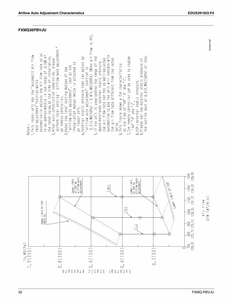
10.Airflow Auto Adjustment Characteristics
FXMQ07PBVJU / FXMQ09PBVJU
3D06
6128
E
26 FXMQ-PBVJU

EDUS391503-F4 Airflow Auto Adjustment Characteristics
FXMQ12PBVJU
3D08
6929
B
FXMQ-PBVJU 27

Airflow Auto Adjustment Characteristics EDUS391503-F4
FXMQ15PBVJU
3D08
7746
B
28 FXMQ-PBVJU

EDUS391503-F4 Airflow Auto Adjustment Characteristics
FXMQ18PBVJU
3D06
6130
F
FXMQ-PBVJU 29

Airflow Auto Adjustment Characteristics EDUS391503-F4
FXMQ24PBVJU
3D06
6131
F
30 FXMQ-PBVJU

EDUS391503-F4 Airflow Auto Adjustment Characteristics
FXMQ30PBVJU
3D08
7747
B
FXMQ-PBVJU 31
Airflow Auto Adjustment Characteristics EDUS391503-F4
FXMQ36PBVJU
3D06
6133
F
32 FXMQ-PBVJU
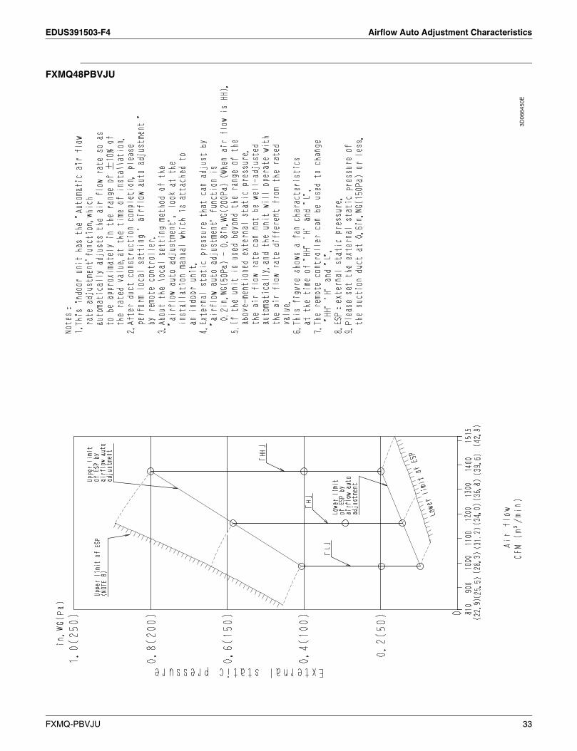
EDUS391503-F4 Airflow Auto Adjustment Characteristics
FXMQ48PBVJU
3D06
6450
E
FXMQ-PBVJU 33

Sound Levels (Reference Data) EDUS391503-F4
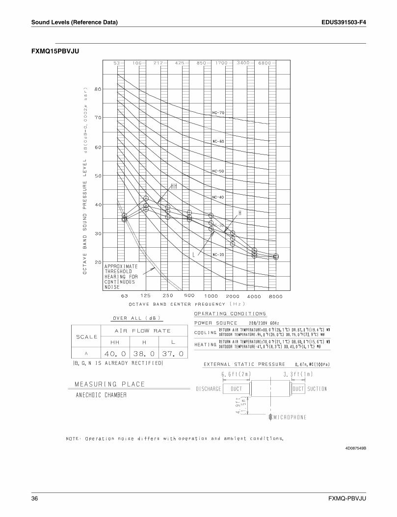
11.Sound Levels (Reference Data)
FXMQ07PBVJU / FXMQ09PBVJU
4D087546B
34 FXMQ-PBVJU

EDUS391503-F4 Sound Levels (Reference Data)
FXMQ12PBVJU
4D087550B
FXMQ-PBVJU 35
Sound Levels (Reference Data) EDUS391503-F4
FXMQ15PBVJU
4D087549B
36 FXMQ-PBVJU

EDUS391503-F4 Sound Levels (Reference Data)
FXMQ18PBVJU
4D087551B
FXMQ-PBVJU 37

Sound Levels (Reference Data) EDUS391503-F4
FXMQ24PBVJU
4D087552B
38 FXMQ-PBVJU

EDUS391503-F4 Sound Levels (Reference Data)
FXMQ30PBVJU / FXMQ36PBVJU
4D087554B
FXMQ-PBVJU 39

Sound Levels (Reference Data) EDUS391503-F4
FXMQ48PBVJU
4D087555B
40 FXMQ-PBVJU

EDUS391503-F4 Sound Levels (Reference Data)
FXMQ54PBVJU
4D087556B
FXMQ-PBVJU 41

Center of Gravity EDUS391503-F4
12.Center of Gravity
FXMQ07PBVJU / FXMQ09PBVJU / FXMQ12PBVJU / FXMQ15PBVJU / FXMQ18PBVJU / FXMQ24PBVJU / FXMQ30PBVJU / FXMQ36PBVJU / FXMQ48PBVJU / FXMQ54PBVJU
C: 4D086926B
Unit: in. (mm)
42 FXMQ-PBVJU
EDUS391503-F4 Accessories
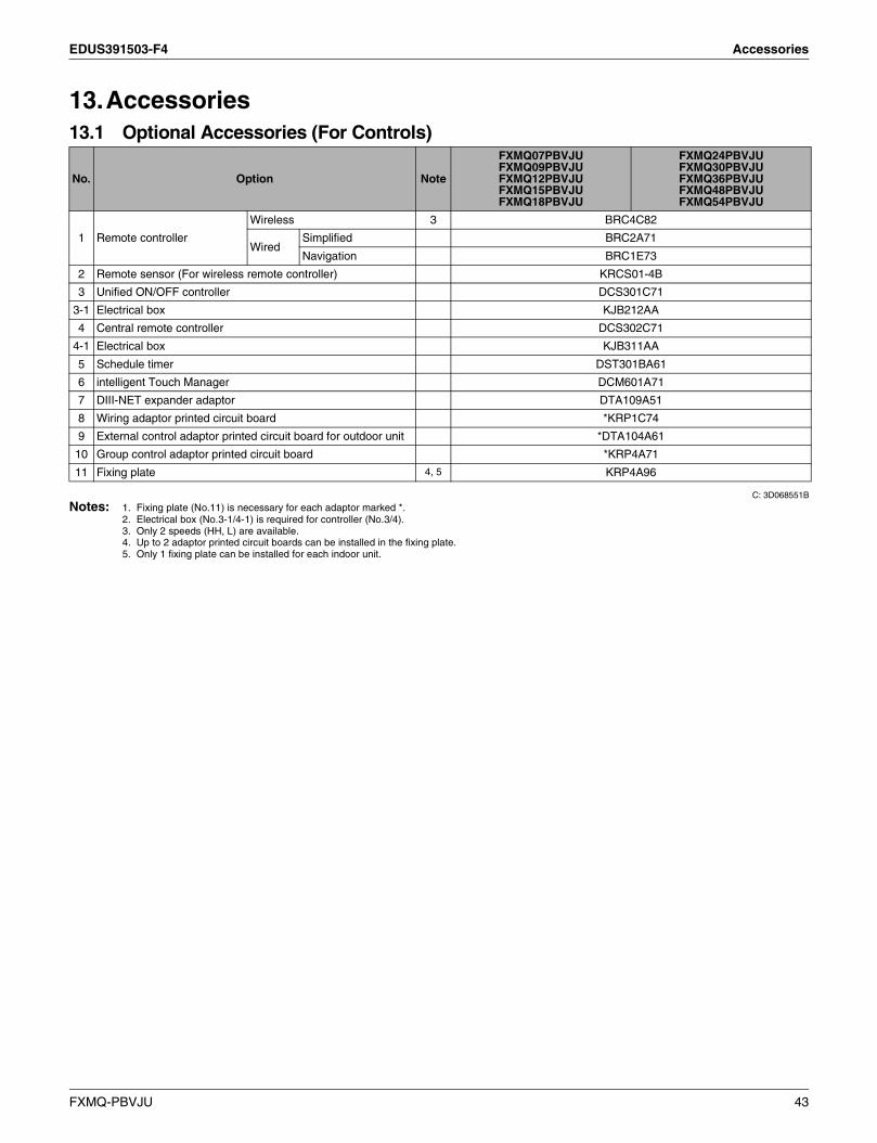
13.Accessories13.1 Optional Accessories (For Controls)
C: 3D068551B
Notes: 1. Fixing plate (No.11) is necessary for each adaptor marked *.2. Electrical box (No.3-1/4-1) is required for controller (No.3/4).3. Only 2 speeds (HH, L) are available.4. Up to 2 adaptor printed circuit boards can be installed in the fixing plate.5. Only 1 fixing plate can be installed for each indoor unit.
No. Option Note
FXMQ07PBVJUFXMQ09PBVJUFXMQ12PBVJUFXMQ15PBVJUFXMQ18PBVJU
FXMQ24PBVJUFXMQ30PBVJUFXMQ36PBVJUFXMQ48PBVJUFXMQ54PBVJU
1 Remote controller
Wireless 3 BRC4C82
WiredSimplified BRC2A71
Navigation BRC1E73
2 Remote sensor (For wireless remote controller) KRCS01-4B
3 Unified ON/OFF controller DCS301C71
3-1 Electrical box KJB212AA
4 Central remote controller DCS302C71
4-1 Electrical box KJB311AA
5 Schedule timer DST301BA61
6 intelligent Touch Manager DCM601A71
7 DIII-NET expander adaptor DTA109A51
8 Wiring adaptor printed circuit board *KRP1C74
9 External control adaptor printed circuit board for outdoor unit *DTA104A61
10 Group control adaptor printed circuit board *KRP4A71
11 Fixing plate 4, 5 KRP4A96
FXMQ-PBVJU 43

Auxiliary Electric Heater Setting EDUS391503-F4
14.Auxiliary Electric Heater SettingAuxiliary electric heater ON/OFF temperature setting• While in heating operation, the heater control (ON/OFF) is conducted as shown below;
• Perform field setting using the remote controller.
* factory set
ON Set temperature
OFF
<Ton: F˚>
<Toff: F˚>
Mode No. FIRST CODE NO. CODE
SECOND CODE NO.
01* 02 03 04 05 06
10 (20) 7<Ton> -7.2 -6.3 -5.4 -4.5 -3.6 -2.7
<Toff> -3.6 -2.7 -1.8 -0.9 0 0.9
44 FXMQ-PBVJU

EDUS391503-F4 Appendix
FXMQ-PBVJU i
Appendix
1.Installation Manual ....................................................................................... 1

EDUS391503-F4 Appendix
1. Installation ManualFXMQ07PBVJU / FXMQ09PBVJU / FXMQ12PBVJU / FXMQ15PBVJU / FXMQ18PBVJU / FXMQ24PBVJU / FXMQ30PBVJU / FXMQ36PBVJU / FXMQ48PBVJU / FXMQ54PBVJU
3PN14093-18K
VRV SYSTEM Inverter Air Conditioners Installation manual
English 1
CONTENTS
1. SAFETY CONSIDERATIONS .......................................... 1
2. BEFORE INSTALLATION ................................................ 3
3. SELECTING INSTALLATION SITE.................................. 4
4. PREPARATIONS BEFORE INSTALLATION ................... 5
5. INDOOR UNIT INSTALLATION........................................ 6
6. REFRIGERANT PIPING WORK....................................... 7
7. DRAIN PIPING WORK ..................................................... 8
8. DUCT WORK.................................................................. 10
9. ELECTRIC WIRING WORK............................................ 11
10. WIRING EXAMPLE AND HOW TO SET
THE REMOTE CONTROLLER....................................... 11
11. FIELD SETTING ............................................................. 14
12. TEST OPERATION ........................................................ 16
1. SAFETY CONSIDERATIONS
Read these SAFETY CONSIDERATIONS for Installation
carefully before installing air conditioning equipment. After com-
pleting the installation, make sure that the unit operates prop-
erly during the startup operation.
Instruct the customer on how to operate and maintain the unit.
Inform customers that they should store this Installation Manual
with the Operation Manual for future reference.
Always use a licensed installer or contractor to install this prod-
uct. Improper installation can result in water or refrigerant leak-
age, electrical shock, fire, or explosion.
Meanings of DANGER, WARNING, CAUTION, and NOTE
Symbols:
DANGER................. Indicates an imminently hazardous
situation which, if not avoided, will
result in death or serious injury.
WARNING............... Indicates a potentially hazardous situ-
ation which, if not avoided, could result
in death or serious injury.
CAUTION................ Indicates a potentially hazardous situ-
ation which, if not avoided, may result
in minor or moderate injury. It may also
be used to alert against unsafe prac-
tices.
NOTE ...................... Indicates situations that may result in
equipment or property-damage acci-
dents only.
DANGER
• Refrigerant gas is heavier than air and replaces oxygen.
A massive leak can lead to oxygen depletion, especially
in basements, and an asphyxiation hazard could occur
leading to serious injury or death.
• Do not ground units to water pipes, gas pipes, telephone
wires, or lightning rods as incomplete grounding can
cause a severe shock hazard resulting in severe injury or
death. Additionally, grounding to gas pipes could cause a
gas leak and potential explosion causing severe injury or
death.
• If refrigerant gas leaks during installation, ventilate the
area immediately. Refrigerant gas may produce toxic gas
if it comes in contact with fire. Exposure to this gas could
cause severe injury or death.
• After completing the installation work, check that the re-
frigerant gas does not leak throughout the system.
• Do not install unit in an area where flammable materials
are present due to risk of explosions that can cause seri-
ous injury or death.
• Safely dispose all packing and transportation materials
in accordance with federal/state/local laws or ordinanc-
es. Packing materials such as nails and other metal or
wood parts, including plastic packing materials used for
transportation may cause injuries or death by suffoca-
tion.
WARNING
• Only qualified personnel must carry out the installation
work. Installation must be done in accordance with this
installation manual. Improper installation may result in
water leakage, electric shock, or fire.
• When installing the unit in a small room, take measures
to keep the refrigerant concentration from exceeding al-
lowable safety limits. Excessive refrigerant leaks, in the
event of an accident in a closed ambient space, can lead
to oxygen deficiency.
• Use only specified accessories and parts for installation
work. Failure to use specified parts may result in water
leakage, electric shocks, fire, or the unit falling.
• Install the air conditioner on a foundation strong enough
that it can withstand the weight of the unit. A foundation
of insufficient strength may result in the unit falling and
causing injuries.
• Take into account strong winds, typhoons, or earth-
quakes when installing. Improper installation may result
in the unit falling and causing accidents.
• Make sure that a separate power supply circuit is provid-
ed for this unit and that all electrical work is carried out
by qualified personnel according to local, state and na-
tional regulations. An insufficient power supply capacity
or improper electrical construction may lead to electric
shocks or fire.
• Make sure that all wiring is secured, that specified wires
are used, and that no external forces act on the terminal
connections or wires. Improper connections or installa-
tion may result in fire.
• When wiring, position the wires so that the control box
cover can be securely fastened. Improper positioning of
the control box cover may result in electric shocks, fire,
or the terminals overheating.
FXMQ-PBVJU 1

Appendix EDUS391503-F4
3PN14093-18K
2 English
• Before touching electrical parts, turn off the unit.
• This equipment can be installed with a Ground-Fault Cir-
cuit Interrupter (GFCI). Although this is a recognized mea-
sure for additional protection, with the grounding system
in North America, a dedicated GFCI is not necessary.
• Securely fasten the outdoor unit terminal cover (panel). If
the terminal cover/panel is not installed properly, dust or
water may enter the outdoor unit causing fire or electric
shock.
• When installing or relocating the system, keep the refrig-
erant circuit free from substances other than the specified
refrigerant (R410A) such as air. Any presence of air or oth-
er foreign substance in the refrigerant circuit can cause
an abnormal pressure rise or rupture, resulting in injury.
• Do not change the setting of the protection devices. If the
pressure switch, thermal switch, or other protection de-
vice is shorted and operated forcibly, or parts other than
those specified by Daikin are used, fire or explosion may
occur.
CAUTION
• Do not touch the switch with wet fingers. Touching a
switch with wet fingers can cause electric shock.
• Do not allow children to play on or around the unit to pre-
vent injury.
• Do not touch the refrigerant pipes during and immediate-
ly after operation as the refrigerant pipes may be hot or
cold, depending on the condition of the refrigerant flow-
ing through the refrigerant piping, compressor, and other
refrigerant cycle parts. Your hands may suffer burns or
frostbite if you touch the refrigerant pipes. To avoid inju-
ry, give the pipes time to return to normal temperature or,
if you must touch them, be sure to wear proper gloves.
• Heat exchanger fins are sharp enough to cut.
To avoid injury wear glove or cover the fins when working
around them.
• Install drain piping to proper drainage. Improper drain
piping may result in water leakage and property damage.
• Insulate piping to prevent condensation.
• Be careful when transporting the product.
• Do not turn off the power supply immediately after stop-
ping operation. Always wait for at least 5 minutes before
turning off the power supply. Otherwise, water leakage
may occur.
• Do not use a charging cylinder. Using a charging cylinder
may cause the refrigerant to deteriorate.
• Refrigerant R410A in the system must be kept clean, dry,
and tight.
(a) Clean and Dry -- Foreign materials (including mineral
oils such as SUNISO oil or moisture) should be pre-
vented from getting into the system.
(b) Tight -- R410A does not contain any chlorine, does
not destroy the ozone layer, and does not reduce the
earth’s protection again harmful ultraviolet radiation.
R410A can contribute to the greenhouse effect if it is
released. Therefore take proper measures to check
for the tightness of the refrigerant piping installation.
Read the chapter Refrigerant Piping Work and follow
the procedures.
• Since R410A is a blend, the required additional refriger-
ant must be charged in its liquid state. If the refrigerant is
charged in a state of gas, its composition can change and
the system will not work properly.
• The indoor unit is for R410A. See the catalog for indoor
models that can be connected. Normal operation is not
possible when connected to other units.
• Remote controller (wireless kit) transmitting distance
can be shorter than expected in rooms with electronic
fluorescent lamps (inverter or rapid start types). Install
the indoor unit far away from fluorescent lamps as much
as possible.
• Indoor units are for indoor installation only. Outdoor
units can be installed either outdoors or indoors.
• Do not install the air conditioner in the following loca-
tions:
(a) Where a mineral oil mist or oil spray or vapor is pro-
duced, for example, in a kitchen.
Plastic parts may deteriorate and fall off or result in
water leakage.
(b) Where corrosive gas, such as sulfurous acid gas, is
produced.
Corroding copper pipes or soldered parts may result
in refrigerant leakage.
(c) Near machinery emitting electromagnetic waves.
Electromagnetic waves may disturb the operation of
the control system and cause the unit to malfunction.
(d) Where flammable gas may leak, where there is car-
bon fiber, or ignitable dust suspension in the air, or
where volatile flammables such as thinner or gaso-
line are handled. Operating the unit in such condi-
tions can cause a fire.
• Take adequate measures to prevent the outdoor unit from
being used as a shelter by small animals. Small animals
making contact with electrical parts can cause malfunc-
tions, smoke, or fire. Instruct the customer to keep the
area around the unit clean.
NOTE
• Install the power supply and transmission wires for the
indoor and outdoor units at least 3.5 feet away from tele-
visions or radios to prevent image interference or noise.
Depending on the radio waves, a distance of 3.5 feet may
not be sufficient to eliminate the noise.
• Dismantling the unit, treatment of the refrigerant, oil and
additional parts must be done in accordance with the rel-
evant local, state, and national regulations.
• Do not use the following tools that are used with conven-
tional refrigerants: gauge manifold, charge hose, gas
leak detector, reverse flow check valve, refrigerant
charge base, vacuum gauge, or refrigerant recovery
equipment.
• If the conventional refrigerant and refrigerator oil are
mixed in R410A, the refrigerant may deteriorate.
• This air conditioner is an appliance that should not be ac-
cessible to the general public.
• The wall thickness of field-installed pipes should be se-
lected in accordance with the relevant local, state, and
national regulations.
2 FXMQ-PBVJU
EDUS391503-F4 Appendix
3PN14093-18K
English 3
2. BEFORE INSTALLATION
• When moving the unit while removing it from the carton
box, be sure to lift it by holding on to the four lifting lugs
without exerting any pressure on other parts, especially,
the refrigerant piping, drain piping, flanges and other
resin parts.
• Be sure to check the type of R410A refrigerant to be used
before installing the unit. (Using an incorrect refrigerant will
prevent normal operation of the unit.)
• The accessories needed for installation must be retained in
your custody until the installation work is completed. Do not
discard them!
• Decide upon a line of transport.
• Leave the unit inside its packaging while moving, until reach-
ing the installation site. Where unpacking is unavoidable, use
a sling of soft material or protective plates together with a
rope when lifting, to avoid damage or scratches to the unit.
• When moving the unit or after opening, hold the unit by the
hanger brackets (× 4). Do not apply force to the refrigerant
piping, drain piping, flanges or plastic parts.
• For the installation of outdoor unit, refer to the installation
manual attached to the outdoor unit.
• Do not install or operate the unit in rooms mentioned below.
• Laden with mineral oil, or filled with oil vapor or spray
like in kitchens. (Plastic parts may deteriorate which
could eventually cause the unit to fall out of place, or
could lead to leaks.)
• Where corrosive gas like sulfurous gas exists. (Cop-
per tubing and brazed spots may corrode which could
eventually lead to refrigerant leaks.)
• Where exposed to combustible gases and where vol-
atile flammable gas like thinner or gasoline is used.
(Gas in the vicinity of the unit could ignite.)
• Where machines can generate electromagnetic
waves. (Control system may malfunction.)
• Where the air contains high levels of salt such as that
near the ocean and where voltage fluctuates greatly
such as that in factories.
Also in vehicles or vessels.
• This unit, both indoor and outdoor, is suitable for installation in a
commercial and light industrial environment.
If installed as a household appliance it could cause electro-
magnetic interference.
2-1 PRECAUTIONS
• Be sure to read this manual before installing the indoor unit.
• Entrust installation to the place of purchase or a qualified ser-
viceman. Improper installation could lead to leaks and, in
worse cases, electric shock or fire.
• Use only parts provided with the unit or parts satisfying
required specifications. Unspecified parts could cause the
unit to fall out of place, or could lead to leaks and, in worse
cases, electric shock or fire.
• Be sure to mount an air filter (part to be procured in the field)
in the suction air passage in order to prevent water leaking,
etc.
2-2 ACCESSORIES
Check that the following accessories are provided and that each
accessory is correct in amount.
Refer to the Fig. 1 of this page.
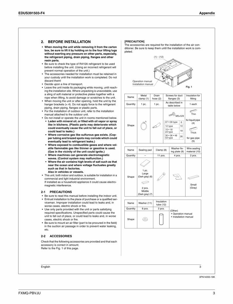
[PRECAUTION]
The accessories are required for the installation of the air con-
ditioner. Be sure to keep them until the installation work is com-
pleted.
NameMetal
clamp (1)
Drain
hose (2)
Screws for duct
flanges (3)
Insulation for
fitting
Quantity 1 pc. 1 pc.As described in
table below1 each
Shape
for liquid pipe
(4)
for gas pipe
(5)
Name Sealing pad Clamp (8)Washer fix-
ing plate (9)
Wire sealing
material (10)
Quantity – 11 pcs. 4 pcs. 2 pcs.
Shape
1 pc.
Large
(Dark gray) (6)
2 pcs.
Middle
(Dark gray) (7)
Small
(Gray)
Name Washer (11)Insulation
tube (12)
(Other)
• Operation manual
• Installation manual
Quantity 8 pcs. 2 pcs.
Shape
Operation manual
Installation manual
(1) - (12)
Fig. 1
15 • 1824 type
30 • 36 • 4854 type
18
10
07 • 09 type 6
26
M5×5/8
12 type
Thin
Thick
FXMQ-PBVJU 3
Appendix EDUS391503-F4
3PN14093-18K
4 English
2-3 OPTIONAL ACCESSORIES
• There is one type of remote controller: wired.
NOTE
• If you wish to use a remote controller that is different from the
above, select a suitable remote controller after consulting
catalogs and technical materials.
FOR THE FOLLOWING ITEMS, TAKE SPECIAL
CARE DURING CONSTRUCTION AND CHECK
AFTER INSTALLATION IS FINISHED.
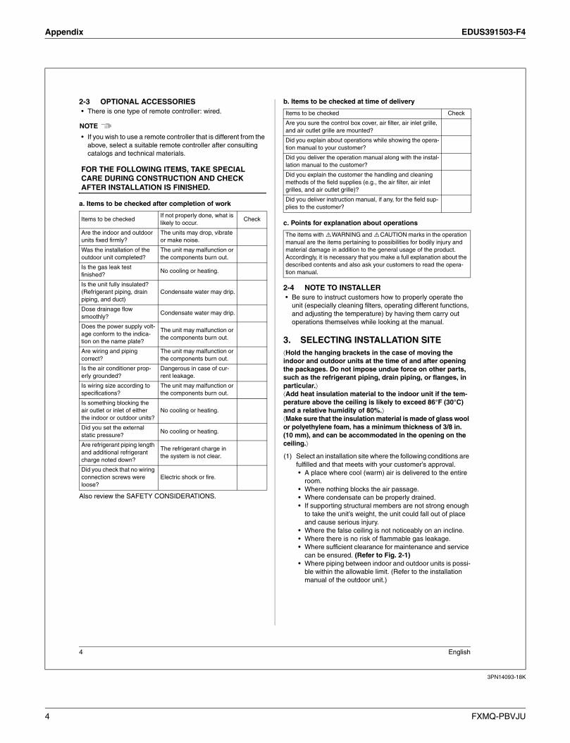
a. Items to be checked after completion of work
Also review the SAFETY CONSIDERATIONS.
b. Items to be checked at time of delivery
c. Points for explanation about operations
2-4 NOTE TO INSTALLER
• Be sure to instruct customers how to properly operate the
unit (especially cleaning filters, operating different functions,
and adjusting the temperature) by having them carry out
operations themselves while looking at the manual.
3. SELECTING INSTALLATION SITE
Hold the hanging brackets in the case of moving the
indoor and outdoor units at the time of and after opening
the packages. Do not impose undue force on other parts,
such as the refrigerant piping, drain piping, or flanges, in
particular.
Add heat insulation material to the indoor unit if the tem-
perature above the ceiling is likely to exceed 86°F (30°C)
and a relative humidity of 80%.
Make sure that the insulation material is made of glass wool
or polyethylene foam, has a minimum thickness of 3/8 in.
(10 mm), and can be accommodated in the opening on the
ceiling.
(1) Select an installation site where the following conditions are
fulfilled and that meets with your customer’s approval.
• A place where cool (warm) air is delivered to the entire
room.
• Where nothing blocks the air passage.
• Where condensate can be properly drained.
• If supporting structural members are not strong enough
to take the unit’s weight, the unit could fall out of place
and cause serious injury.
• Where the false ceiling is not noticeably on an incline.
• Where there is no risk of flammable gas leakage.
• Where sufficient clearance for maintenance and service
can be ensured. (Refer to Fig. 2-1)
• Where piping between indoor and outdoor units is possi-
ble within the allowable limit. (Refer to the installation
manual of the outdoor unit.)
Items to be checkedIf not properly done, what is
likely to occur.Check
Are the indoor and outdoor
units fixed firmly?
The units may drop, vibrate
or make noise.
Was the installation of the
outdoor unit completed?
The unit may malfunction or
the components burn out.
Is the gas leak test
finished? No cooling or heating.
Is the unit fully insulated?
(Refrigerant piping, drain
piping, and duct)
Condensate water may drip.
Dose drainage flow
smoothly?Condensate water may drip.
Does the power supply volt-
age conform to the indica-
tion on the name plate?
The unit may malfunction or
the components burn out.
Are wiring and piping
correct?
The unit may malfunction or
the components burn out.
Is the air conditioner prop-
erly grounded?
Dangerous in case of cur-
rent leakage.
Is wiring size according to
specifications?
The unit may malfunction or
the components burn out.
Is something blocking the
air outlet or inlet of either
the indoor or outdoor units?
No cooling or heating.
Did you set the external
static pressure? No cooling or heating.
Are refrigerant piping length
and additional refrigerant
charge noted down?
The refrigerant charge in
the system is not clear.
Did you check that no wiring
connection screws were
loose?
Electric shock or fire.
Items to be checked Check
Are you sure the control box cover, air filter, air inlet grille,
and air outlet grille are mounted?
Did you explain about operations while showing the opera-
tion manual to your customer?
Did you deliver the operation manual along with the instal-
lation manual to the customer?
Did you explain the customer the handling and cleaning
methods of the field supplies (e.g., the air filter, air inlet
grilles, and air outlet grille)?
Did you deliver instruction manual, if any, for the field sup-
plies to the customer?
The items with WARNING and CAUTION marks in the operation
manual are the items pertaining to possibilities for bodily injury and
material damage in addition to the general usage of the product.
Accordingly, it is necessary that you make a full explanation about the
described contents and also ask your customers to read the opera-
tion manual.
4 FXMQ-PBVJU

EDUS391503-F4 Appendix
3PN14093-18K
English 5
CAUTION
• Install the indoor and outdoor units, power supply wiring and
connecting wires at least 3.3 ft (1 m) away from televisions or
radios in order to prevent wave interference or noise.
(Depending on the radio waves, a distance of 3.3 ft (1 m) may
not be sufficient enough to eliminate the noise.)
• In the case of the installation of a wireless remote controller, the transmission distance of the wireless remote controller may be shortened if the room has a fluorescent light of electronic light-ing type (i.e., an inverter or rapid-start fluorescent light).Keep the distance between the receiver and the fluorescent light as far as possible.
(2) Use hanging bolts to install the indoor unit. Check that the place of installation withstands the weight of the indoor unit. Secure the hanging bolts with proper beams if necessary.
4. PREPARATIONS BEFORE INSTALLATION
(1) Check the positional relationship between the ceiling open-ing hole and the hanging bolt of the unit.• For the maintenance, inspection, and other servicing
purposes of the control box and drain pump, prepare one of the following service spaces.1. Inspection hatch 1 (17-3/4 in. (450 mm) × 17-3/4 in.
(450 mm)) for the control box and a minimum space of 12 in. (300 mm) for the lower part of the product. (Refer to Fig. 2-2)
2. Inspection hatch 1 (17-3/4 in. (450 mm) × 17-3/4 in. (450 mm)) for the control box and inspection hatch 2 for the lower part of the product (see arrow view A-1). (Refer to Fig. 2-3)
3. Inspection hatch 3 for the lower part of the product and the lower part of the control box (see arrow view A-2). (Refer to Fig. 2-3)
[Unit: in. (mm)]
Ceiling
Floor surface
• The H1 dimension indicates the
height of the product.
• Determine the H2 dimension by
maintaining a downward slope of
at least 1/100 as specified in
7. DRAIN PIPING WORK.
Min
. 1
(2
0)
Min
. 12
(300)
Min
. 18
(450
)
Min
. 99 (
2500)
Min. 28 (700) (service space)(If no c
eili
ng b
oard
is p
rovi
ded.)
*H1=
12 (
300)
*H2=
Min
. 25 (
620)
[Required installation place]
The dimensions indicate the
minimum required space of
installation.
Fig. 2-1
28 (700)
24-13/16 (631)
(Hanging bolt pitch)
Inspection hatch 1
(17-3/4 (450) ×
17-3/4 (450))
Inspection hatch
Control box
Control box
Ceiling
B C
(Ha
ng
ing
bo
lt p
itch
)
Bottom of unit
Air inlet
Air outlet
Hanging bolt (× 4)
*H3
=M
in.
12
(3
00
)
Fig. 2-2
Case 1[Unit: in. (mm)]
28 (700) 28 (700)
Inspection hatch
Inspection hatch 1
(17-3/4 (450) ×
17-3/4 (450))
Inspection
hatch 2
Inspection hatch 3
(Same as the indoor unit size +12 (300) or more)
Control box
Control box
Control box
Inspection hatch
(Ceiling opening)
Ceiling
Arrow view A-1 Arrow view A-2
Min
. D
=B
+1
2 (
30
0)M
in.
8
(20
0)
B
*H3
=M
in.
3/4
(2
0)
07 • 09 type 22 (550) 23-1/8 (588) 34 (850)
28 (700) 29 (738) 40 (1000)
Model B C D
40 (1000) 40-7/8 (1038) 52 (1300)
56 (1400) 56-5/8 (1438) 68 (1700)
15 • 18 • 24 type
12 type
30 • 36 • 48 • 54 type
[Unit: in. (mm)]
A
Fig. 2-3
Case 2, 3
(Same as the
indoor unit
size or more)
• Determine the H3 dimension by maintaining a downward
slope of at least 1/100 as specified in 7. DRAIN PIPING
WORK.
FXMQ-PBVJU 5
Appendix EDUS391503-F4
3PN14093-18K
6 English
(2) Mount the canvas ducts to the air outlet and inlet so that the
vibration of the air conditioner will not be transmitted to the
duct or ceiling. Apply a sound-absorbing material (insula-
tion material) to the inner wall of the duct and vibration insu-
lation rubber to the hanging bolts (refer to 8. DUCT WORK).
(3) Open installation holes (if the ceiling already exists).
• Open the installation holes on the ceiling. Lay the refrig-
erant piping, drain piping, power line, transmission wir-
ing, and remote controller wiring for the piping and wiring
connection port of the unit.
In the case of the installation of a wireless remote con-
troller, refer to the installation manual provided with the
wireless remote controller.
Refer to 6. REFRIGERANT PIPING WORK, 7. DRAIN
PIPING WORK, and 10. WIRING EXAMPLE AND HOW
TO SET THE REMOTE CONTROLLER.
• The ceiling framework may need reinforcement in order
to keep the ceiling horizontal and prevent the vibration of
the ceiling after the installation holes are opened. For
details, consult your construction or interior contractor.
(4) Install the hanging bolts. Make sure that the hanging bolts
are M10 in size.
• Use hole-in anchors if the hanging bolts already exist;
otherwise use embedded inserts and embedded founda-
tion bolts so that they can withstand the weight of the unit.
Adjust the distance from the ceiling surface in advance.
5. INDOOR UNIT INSTALLATION
It may be easier to install accessories (sold separately)
before installing the indoor unit. Refer to the installation
manuals provided to the accessories as well.
Be sure to use the accessories and specified parts for
installation work.
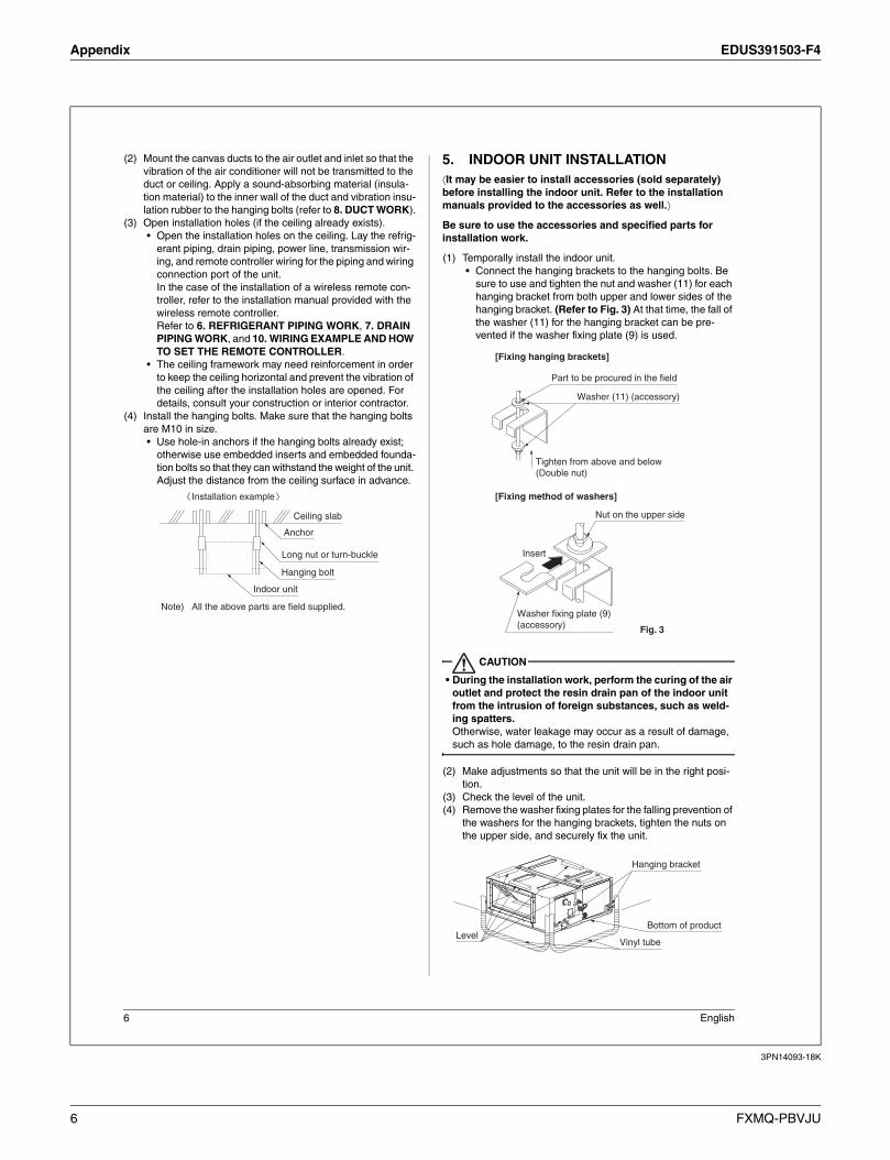
(1) Temporally install the indoor unit.
• Connect the hanging brackets to the hanging bolts. Be
sure to use and tighten the nut and washer (11) for each
hanging bracket from both upper and lower sides of the
hanging bracket. (Refer to Fig. 3) At that time, the fall of
the washer (11) for the hanging bracket can be pre-
vented if the washer fixing plate (9) is used.
CAUTION
• During the installation work, perform the curing of the air
outlet and protect the resin drain pan of the indoor unit
from the intrusion of foreign substances, such as weld-
ing spatters.
Otherwise, water leakage may occur as a result of damage,
such as hole damage, to the resin drain pan.
(2) Make adjustments so that the unit will be in the right posi-
tion.
(3) Check the level of the unit.
(4) Remove the washer fixing plates for the falling prevention of
the washers for the hanging brackets, tighten the nuts on
the upper side, and securely fix the unit.
Note) All the above parts are field supplied.
Installation example
Ceiling slab
Anchor
Long nut or turn-buckle
Hanging bolt
Indoor unit
Washer (11) (accessory)
Part to be procured in the field
Washer fixing plate (9)
(accessory)
Insert
Tighten from above and below
(Double nut)
[Fixing hanging brackets]
[Fixing method of washers]
Fig. 3
Nut on the upper side
Hanging bracket
Bottom of productLevel
Vinyl tube
6 FXMQ-PBVJU
EDUS391503-F4 Appendix
3PN14093-18K
English 7
CAUTION
• Use the level and check that the unit is installed horizontally.
(4 directions)
• In the case of using a vinyl tube (filled with water) in place of
the level, align the bottom of the unit to the water surface at
both edges of the vinyl tube to make levelness adjustment.
If the unit is installed at a slant with the drain pipe side set
high, in particular, the float switch will not operate normally
and water leakage may result.
6. REFRIGERANT PIPING WORK
As for the refrigerant piping of the outdoor unit, refer to the
installation manual provided to the outdoor unit.
Perform heat insulation work on both gas piping and liquid
piping, or otherwise water leakage may result.
Use the insulation material that withstands a temperature
of 248°F (120°C).
Reinforce the insulation material for the refrigerant piping if
the ambient temperature is high, or otherwise dew conden-
sation may result on the surface of the insulation material.
Make sure that the refrigerant is R410A before refrigerant
piping work. If the refrigerant is different, the air condi-
tioner will not operate normally.
CAUTION
This product uses new refrigerant (R410A) only. Be sure to
keep the following items and conduct the installation work.
• Use a dedicated pipe cutter and flare tool for R410A.
• When connecting the flare, apply ether oil or ester oil
only to inner side of the flare.
• Be sure to use the flare nut provided with the unit. (Do
not use a different flare nut (such as a type-1 flare nut),
or otherwise refrigerant leakage may result.)
• Perform the curing of the piping with pinching or taping
of the piping in order to prevent the intrusion of dirt, dust,
and moisture into the piping.
CAUTION
• Be sure to use the specified type of refrigerant for the
refrigeration cycle and do not contaminate the refrigerant
with air.
• Ventilate the room in case of refrigerant leakage during
installation work.
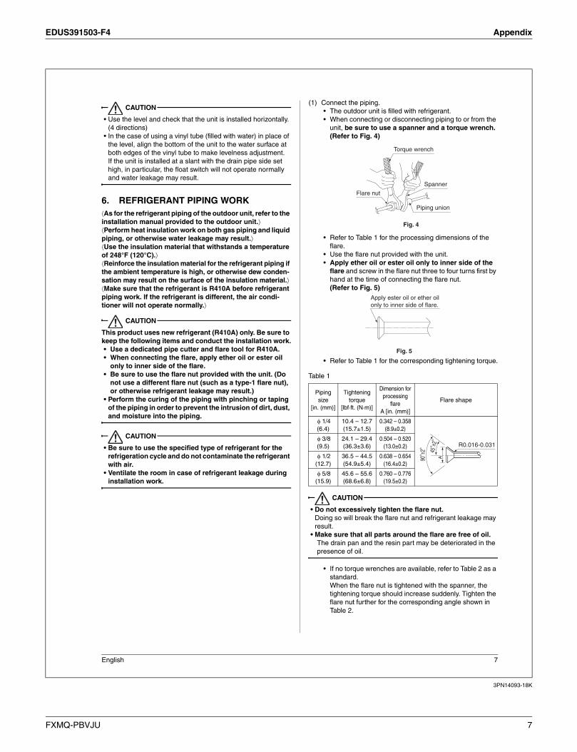
(1) Connect the piping.
• The outdoor unit is filled with refrigerant.
• When connecting or disconnecting piping to or from the
unit, be sure to use a spanner and a torque wrench.
(Refer to Fig. 4)
• Refer to Table 1 for the processing dimensions of the
flare.
• Use the flare nut provided with the unit.
• Apply ether oil or ester oil only to inner side of the
flare and screw in the flare nut three to four turns first by
hand at the time of connecting the flare nut.
(Refer to Fig. 5)
• Refer to Table 1 for the corresponding tightening torque.
Table 1
CAUTION
• Do not excessively tighten the flare nut.
Doing so will break the flare nut and refrigerant leakage may
result.
• Make sure that all parts around the flare are free of oil.
The drain pan and the resin part may be deteriorated in the
presence of oil.
• If no torque wrenches are available, refer to Table 2 as a
standard.
When the flare nut is tightened with the spanner, the
tightening torque should increase suddenly. Tighten the
flare nut further for the corresponding angle shown in
Table 2.
Piping
size
[in. (mm)]
Tightening
torque
[lbf·ft. (N·m)]
Dimension for
processing
flare
A [in. (mm)]
Flare shape
1/4
(6.4)
10.4 – 12.7
(15.7±1.5)
0.342 – 0.358
(8.9±0.2)
3/8
(9.5)
24.1 – 29.4
(36.3±3.6)
0.504 – 0.520
(13.0±0.2)
1/2
(12.7)
36.5 – 44.5
(54.9±5.4)
0.638 – 0.654
(16.4±0.2)
5/8
(15.9)
45.6 – 55.6
(68.6±6.8)
0.760 – 0.776
(19.5±0.2)
Torque wrench
Spanner
Piping union
Flare nut
Fig. 4
Fig. 5
Apply ester oil or ether oil
only to inner side of flare.
A
450
± 20
R0.016-0.031
900± 2
0
FXMQ-PBVJU 7

Appendix EDUS391503-F4
3PN14093-18K
8 English
Table 2
(2) On completion of installation work, check that there is no
gas leakage.
(3) Refer to the following illustration and be sure to perform
heat insulation work on the piping joints after gas leakage
checks. (Refer to Fig. 6)
• Use the insulation for fitting (4) and (5) provided to the
liquid piping and gas piping, respectively, and conduct
heat insulation work.
(Tighten both edges of the insulation for fitting (4) and (5)
for each joint with the clamp (8).)
• Make sure that the joint of the insulation for fitting (4) and
(5) for the joint on the liquid piping and gas piping side
faces upward.
• Wrap the middle sealing material (7) around the insula-
tion for fitting (4) and (5) for the joint (flare nut part).
CAUTION
• Be sure to perform the heat insulation of the local piping
up to the piping joint.
If the piping is exposed, dew condensation may result. Fur-
thermore, a burn may be caused if a human body comes in
contact with the piping.
• Perform nitrogen substitution or charge the refrigerant
piping with nitrogen (see NOTE 1) in the case of refriger-
ant piping brazing (see NOTE 2). Then perform the flare
connection of the indoor unit. (Refer to Fig. 7)
CAUTION
• Do not use any antioxidant at the time of piping brazing.
The piping may be clogged with a residual antioxidant and
parts may malfunction.
NOTE
1. At the time of brazing, set the pressure of nitrogen to approximately 2.9 PSI (0.02 MPa) (close to the pressure of a breeze coming in contact with the cheek) with a pres-sure reducing valve.
2. Do not use flux at the time of brazing and connecting the refrigerant piping. Use a copper phosphorus brazing alloy (BCuP-2/BCu 93P-710/795), which does not require flux, for brazing.(Flux has a bad influence on the refrigerant piping. Chlo-rine-based flux will cause piping corrosion. Furthermore, if it contains fluorine, the flux will deteriorate refrigerant oil.)
• As for the branching of the refrigerant piping or refrigerant,
refer to the installation manual provided with the outdoor unit.
7. DRAIN PIPING WORK
(1) Conduct drain piping work.
Check that the piping
ensures proper draining.
• Make sure that the diam-
eter of the piping exclud-
ing the rising part is the
same as or larger than
the diameter of the con-
necting pipe (vinyl chloride pipe with an outer diameter
of 1-1/4 in. (32 mm) and a nominal inner diameter of 31/
32 in. (25 mm)).
• Make sure that the piping is short enough with a down-
ward slope of at least 1/100 and that there is no air
bank formed. No drain trap is required.
Piping size
[in. (mm)]
Tightening
angle
Recommended arm length of
tool used
1/4 (6.4) 60° – 90° Approx. 6 in. (150 mm)
3/8 (9.5) 60° – 90° Approx. 8 in. (200 mm)
1/2 (12.7) 30° – 60° Approx. 10 in. (250 mm)
5/8 (15.9) 30° – 60° Approx. 12 in. (300 mm)
Heat insulation procedure for gas piping
Insulation material for piping (on unit side)
Insulation material for piping (field supply)
Make sure that the seam faces upward.
Clamp (8)
(accessory)
Gas pipe
Liquid pipe
Flare nut joint
Attached to the surface.
Insulation for fitting (5) (accessory)
Middle sealing pad (7)
(accessory)
Wrap the insulation material around the portion from the surface of the main unit to the upper part of the flare nut joint.
Insulation material for piping (field supply)
Wrap the insulation material around the portion from the surface of the main unit to the upper part of the flare nut joint.
Fig. 6
Heat insulation procedure for liquid piping
Insulation material for piping (on unit side) Make sure that
the seam faces upward.
Clamp (8)
(accessory)
Main unit
Flare nut joint
Attached to the surface.
Insulation for fitting (4) (accessory)
Middle sealing pad (7)
(accessory)Nitrogen
Refrigerant piping Part to be
brazed Taping
Pressure reducing valve
Hands valve
Nitrogen
Fig. 7
Refrigerant
piping
Drain socket
Socket for
maintenance
(with rubber cap)
8 FXMQ-PBVJU

EDUS391503-F4 Appendix
3PN14093-18K
English 9
CAUTION
• The drain piping will be clogged with water and water leakage
may result if the water is accumulated in the drain piping.
• Conduct drain-up piping work if the gradient is insuffi-
cient.
• Attach a support bracket at 3.3 to 4.9 ft (1 to 1.5 m)
intervals for the prevention of piping deflection.
• Be sure to use the drain hose (2) and metal clamp (1).
Insert the drain hose (2) deep into the base of the
drain socket, and securely fasten the metal clamp (1)
within the taped part on the insertion front end of the
hose.
Be sure to fasten the screw of the metal clamp (1) until
the margin of the screw thread decreases to 3/16 in.
(4 mm) or less.
NOTE
Be sure to follow the instructions as below.
• Do not connect the drain piping directly to a sewer that
smells of ammonia.
The ammonia in the sewer may reach through the drain
piping and corrode the heat exchanger of the indoor unit.
• Do not bend or twist the provided drain hose (2) in order
not to impose excessive force on the hose. (Doing so
may result in water leakage.)
• Take the procedure shown in the following illustration to
perform concentrated drain piping.
• The Socket for maintenance can be used for natural
drainage as shown below. As the drain pump operation
does not need for natural drainage, it can be disable by
field setting to reduce power consumption.
(Refer to Table 6)
• Select the diameter of the concentrated drain piping to
suit the capacity of equipment connecting to the concen-
trated drain piping.
(2) Check the smooth draining of the piping on completion of
the installation of the piping.
[Before electrical work]
CAUTION
• A licensed electrical engineering technician must con-
duct electrical wiring work (including grounding work).
• If no licensed electrical engineering technician is avail-
able, take steps 3 and 4 after the test operation of the air
conditioner is finished.
1. Remove the control box cover, and connect the single-
phase electric wires to terminals L1 and L2 of the ter-
minal block and the ground wiring to the ground ter-
minal.
Perform wiring according to 10-1. CONNECTING
POWER SUPPLY, GROUND, REMOTE CONTROLLER,
AND TRANSMISSION WIRING in 10. WIRING EXAM-
PLE AND HOW TO SET THE REMOTE CONTROLLER.
3.3 - 4.9 ft
(1 -1.5 m)Support bracket
Downward slope of at least 1/100
(accessory)
(accessory)
Metal clamp (1)
Tape Drain hose (2)
Concentrated drain piping
The drain piping will be clogged with water
and water leakage may result if the water is
accumulated in the drain piping.
Maintain a downward slope of at least
1/100 so that no air bank will be formed.
18
- 3
/8 in
.
(46
7 m
m)
3-1
5/1
6 in
. (1
00
mm
) o
r m
ore
Seal and insulate the drain socket.
Ceiling slab
3.3 - 4.9 ft(1-1.5 m)12 in. (300 mm) max.
28
in
. (7
00
mm
)m
ax.
Support bracket
Drain-up piping
(field supply)
Adjustable
(18-3/8 in. (467 mm) max.)Metal clamp (1) (accessory)
Drain hose (2) (accessory)
Drain hose (2) (accessory)
Horizontal or
upward slope
If there is an air bank, noise may be generated
as a result of a water backflow when the drain
pump comes to a stop.
Locate the drain hose horizontally
or with a little upward gradient.
FXMQ-PBVJU 9

Appendix EDUS391503-F4
3PN14093-18K
10 English
CAUTION
• In order to avoid imposing tension on the wire connections,
perform clamping securely with the provided clamp (8) speci-
fied in 3 in 10-1. CONNECTING POWER SUPPLY, GROUND,
REMOTE CONTROLLER, AND TRANSMISSION WIRING.
2. Check that the control box cover is closed before turning
the air conditioner ON.
3. Provide approximately 61 in3
(1L) of water gradually into
the drain pan through the water inlet on the bottom of the
drain socket or the outlet. Make sure that the water is not
spilled onto the drain pump.
4. The drain pump will operate with the power turned ON.
Check that the pump drains water smoothly. (The drain
pump will stop automatically in 10 minutes.)
The drainage can be checked with the water level change
in the drain pan through the water inlet.
CAUTION
• Do not touch the drain pump.
Otherwise it may result in an electric shock.
• Do not impose external force on the float switch.
Otherwise, a failure may result.
5. On completion of the drainage check, shut off the power
supply and disconnect the power supply line.
6. Put the control box cover to the original position.
[After electrical work]
• After completion of 8. DUCT WORK provide approximately
61 in3
(1L) of water gradually into the drain pan through the
water inlet on the bottom of the drain socket, and check that
the water is drained while the air conditioner is in cooling
operation according to 11. FIELD SETTING and 12. TEST
OPERATION. Make sure that the water is not spilled onto the
electric parts of the drain pump and others.
(3) Be sure to conduct heat insulation work on the follow-
ing portions, or otherwise water leakage may occur as
a result of dew condensation.
• Drain piping indoors
• Drain socket
• On completion of the drainage check, refer to the follow-
ing illustration, and use the provided large sealing pad
(6) and heat insulate the metal clamp (1) and drain hose
(2).
8. DUCT WORK
Pay the utmost attention to the following items and conduct
the ductwork.
• Check that the duct will not be in excess of the setting range
of external static pressure for the unit. (Refer to the technical
datasheet for the setting range. Each model has each setting
range of external static pressure.)
• Attach a canvas duct each to the air outlet and air inlet so that
the vibration of the equipment will not be transmitted to the
duct or ceiling.
Use a sound-absorbing material (insulation material) for the
lining of the duct and apply vibration insulation rubber to the
hanging bolts.
• At the time of duct welding, perform the curing of the duct so
that the sputter will not come in contact with the drain pan for
the filter.
• If the metal duct pass through a metal lath, wire lath, or metal
plate of a wooden structure, separate the duct and wall elec-
trically.
• Be sure to heat insulate the duct for the prevention of dew
condensation. (Material: Glass wool or styrene foam; Thick-
ness: 31/32 in. (25 mm))
• Be sure to attach the field supply air filter to the air inlet of the
unit or field supply inlet in the air passage on the air suction
side. (Be sure to select an air filter with a duct collection effi-
ciency of 50 weight percent.)
• Explain the operation and washing methods of the locally
procured components (i.e., the air filter, air inlet grille, and air
outlet grille) to the customer.
• Locate the air outlet grille on the indoor side for the preven-
tion of drafts in a position where indirect contact with people.
• The air conditioner incorporates a function to adjust the fan to
rated speed automatically. (11. FIELD SETTING)
Therefore, do not use booster fans midway in the duct.
Connection method of ducts on air inlet and outlet sides.
• Connect the field supply duct in alignment with the inner side
of the flange.
• Connect the flange and unit with the flange connection screw
(3).
• Wrap aluminum tape around the flange and duct joint in order
to prevent air leakage.
Water inlet
Drain socket
Drain pan
Control box cover
Terminal block for power supply
Screw
Water inlet cover
Control box
Refrigerant piping
Air outlet
Socket for maintenance
(with rubber cap)
Drain pump position
Plastic water container
Make sure that the
seam faces upward.
Metal clamp (1)
(accessory)
Large sealing pad (6)
(accessory)
3/16 in. (4 mm) max.
Unit
Flange on air outlet side
(provided with the unit)
Insulation material
(field supply)
Canvas duct
(field supply)
Flange on air inlet side
(provided with the unit)
Insulation material
(field supply)
Air inlet Air outlet
Screws for duct
flanges (3)
(accessory) Screws
for duct
flanges (3)
(accessory)
10 FXMQ-PBVJU

EDUS391503-F4 Appendix
3PN14093-18K
English 11
CAUTION
Connect the flange and unit with the flange connection screw (3)
regardless of whether the duct is connected to the air inlet side.
9. ELECTRIC WIRING WORK
9-1 GENERAL INSTRUCTIONS
• All field supplied parts and materials and electric works must
conform to local codes.
• Use copper wire only.
• For electric wiring work, refer to WIRING DIAGRAM attached
to the control box cover.
• For remote controller wiring details, refer to the installation
manual attached to the remote controller.
• All wiring must be performed by an authorized electrician.
• This system consists of multiple indoor units. Mark each
indoor unit as unit A, unit B..., and be sure the terminal board
wiring to the outdoor unit and BS unit are properly matched.
If wiring and piping between the outdoor unit and an indoor
unit are mismatched, the system may cause a malfunction.
• A ground fault circuit interrupter capable of shutting down
power supply to the entire system must be installed.
• Refer to the installation manual attached to the outdoor unit
for the size of power supply wiring connected to the outdoor
unit, the capacity of the ground fault circuit interrupter and
switch, and wiring instructions.
• Be sure to ground the air conditioner.
• Do not connect the ground wiring to gas and water pipes,
lightning rods, or telephone ground wires.
• Gas pipes : might cause explosions or fire if gas leaks.
• Water pipes : no grounding effect if hard vinyl piping is
used.
• Telephone ground wires or lightning rods : might cause
abnormally high electric potential in the ground during
lighting storms.
9-2 ELECTRICAL CHARACTERISTICS
MCA: Minimum Circuit Ampacity (A)
MOP: Maximum Overcurrent Protective Device (A)
kW: Fan Motor Rated Output (kW)
FLA: Full Load Ampacity (A)
9-3 SPECIFICATIONS FOR FIELD SUPPLIED
FUSES AND WIRE
Allowable length of transmission wirings and remote controller
wiring are as follows.
(1) Outdoor unit – Indoor unit:
Max. 3280 ft (1,000 m) (Total wiring length: 6560 ft
(2,000 m))
(2) Indoor unit – Remote controller:
Max. 1640 ft (500 m)
NOTE
1. Shows only in case of protected pipes. Use H07RN-F in case of no protection.
2. Vinyl cord with sheath or cable (Insulated thickness : 1/16 in. (1 mm) or more)
10. WIRING EXAMPLE AND HOW TO SET THE REMOTE CONTROLLER
10-1 CONNECTING POWER SUPPLY, GROUND,
REMOTE CONTROLLER, AND TRANSMISSION
WIRING
(Remove the control box cover as shown below and connect
each wire.)
(1) Remove the control box cover.
ModelPower supply Fan motor
Hz Volts Voltage range MCA MOP kW FLA
FXMQ07PBVJU
60208V
/230V
Max. 253V
Min. 187V
0.6 15 0.090 0.5
FXMQ09PBVJU 0.6 15 0.090 0.5
FXMQ12PBVJU 1.4 15 0.140 1.1
FXMQ15PBVJU 1.5 15 0.350 1.2
FXMQ18PBVJU 1.6 15 0.350 1.3
FXMQ24PBVJU 1.8 15 0.350 1.4
FXMQ30PBVJU 2.3 15 0.350 2.2
FXMQ36PBVJU 2.9 15 0.350 2.3
FXMQ48PBVJU 3.4 15 0.350 2.7
FXMQ54PBVJU 3.4 15 0.350 2.7
Model
Power supply wiringRemote controller wiring
Transmission wiring
Field fuses Size Wire Size
FXMQ07PBVJU
15A
Wiring size
and length
must com-
ply with
local
codes.
2-conductor,
stranded
non-shielded
copper cable
PVC/vinyl
jacket
(NOTE 2)
AWG18-16
FXMQ09PBVJU
FXMQ12PBVJU
FXMQ15PBVJU
FXMQ18PBVJU
FXMQ24PBVJU
FXMQ30PBVJU
FXMQ36PBVJU
FXMQ48PBVJU
FXMQ54PBVJU
Screw
(3 portions)
FXMQ-PBVJU 11
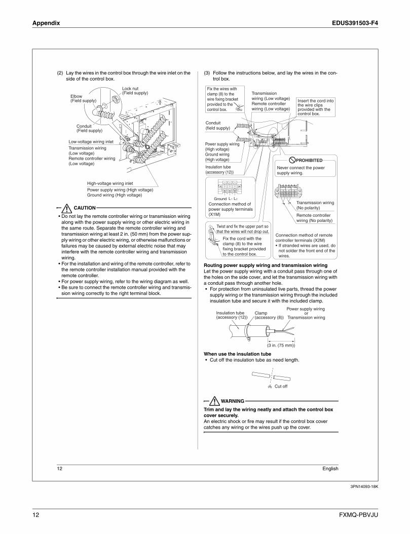
Appendix EDUS391503-F4
3PN14093-18K
12 English
(2) Lay the wires in the control box through the wire inlet on the
side of the control box.
CAUTION
• Do not lay the remote controller wiring or transmission wiring
along with the power supply wiring or other electric wiring in
the same route. Separate the remote controller wiring and
transmission wiring at least 2 in. (50 mm) from the power sup-
ply wiring or other electric wiring, or otherwise malfunctions or
failures may be caused by external electric noise that may
interfere with the remote controller wiring and transmission
wiring.
• For the installation and wiring of the remote controller, refer to
the remote controller installation manual provided with the
remote controller.
• For power supply wiring, refer to the wiring diagram as well.
• Be sure to connect the remote controller wiring and transmis-
sion wiring correctly to the right terminal block.
(3) Follow the instructions below, and lay the wires in the con-
trol box.
Routing power supply wiring and transmission wiring
Let the power supply wiring with a conduit pass through one of
the holes on the side cover, and let the transmission wiring with
a conduit pass through another hole.
• For protection from uninsulated live parts, thread the power
supply wiring or the transmission wiring through the included
insulation tube and secure it with the included clamp.
When use the insulation tube
• Cut off the insulation tube as need length.
WARNING
Trim and lay the wiring neatly and attach the control box
cover securely.
An electric shock or fire may result if the control box cover
catches any wiring or the wires push up the cover.
Low-voltage wiring inlet
Transmission wiring
(Low voltage)
Remote controller wiring
(Low voltage)
Lock nut(Field supply)
Elbow(Field supply)
Conduit(Field supply)
High-voltage wiring inlet
Power supply wiring (High voltage)
Ground wiring (High voltage)L1 L2
1P 2P 1F 2F 1T 2T
Fix the wires with
clamp (8) to the
wire fixing bracket
provided to the
control box.
Insert the cord into the wire clips provided with the control box.
PROHIBITED
Never connect the power
supply wiring.
Connection method of remote
controller terminals (X2M)
• If stranded wires are used, do
not solder the front end of the
wires.
Twist and fix the upper part so
that the wires will not drop out.
Fix the cord with the
clamp (8) to the wire
fixing bracket provided
to the control box.
Remote controller
wiring (No polarity)
Power supply wiring
(High voltage)
Ground wiring
(High voltage)
Transmission wiring
(No polarity)
Transmission
wiring (Low voltage)
Remote controller
wiring (Low voltage)
Ground
Connection method of
power supply terminals
(X1M)
Insulation tube
(accessory (12))
Conduit
(field supply)
Insulation tube(accessory (12))
Clamp(accessory (8))
Power supply wiring or
Transmission wiring
(3 in. (75 mm))
Cut off
12 FXMQ-PBVJU

EDUS391503-F4 Appendix
3PN14093-18K
English 13
(4) Put the control box cover, and wrap the wire sealing mate-
rial (Small) (10) around the conduit so as to block the wire
through holes.
CAUTION
• After all the wiring connections are done, fill in any gaps in the
through holes with putty or insulation (procured locally) to pre-
vent small animals and insects from entering the unit from
outside. (If any do get in, they could cause short circuits in the
control box.)
[Precautions for Power Supply Wiring]
• Connect round crimp-style terminals provided with insulation
sleeves to the terminal block for power supply.
Be sure to follow the instructions provided below if the spec-
ified terminals cannot be used.
Otherwise, abnormal heat may be generated as a result
of the loosening of the wires.
• If stranded wires are used, do not solder the front end of the
wires.
• Connect proper wires securely and fix the wires so that exter-
nal force will not be imposed on the terminals.
• Use an appropriate screwdriver to tighten the terminal
screws. The screw heads may be damaged if the screwdriver
is too small and the terminal screws will not be tightened
properly.
• Do not tighten the terminal screws excessively, or otherwise
the screw heads may be damaged.
• Refer to the table below for the required tightening torque val-
ues of the terminal screws.
10-2 WIRING EXAMPLE
No. 1 system: When using 1 remote controller for 1 indoor
unit
No. 2 system: For group control or use with 2 remote con-
trollers
Tightening torque [lbf·ft. (N·m)]
Terminal block for remote controller
and transmission wires
0.58 - 0.72
(0.80 - 0.96)
Terminal block for power supply
Ground wiring
0.87 - 1.06
(1.18 - 1.44)
Wire through holes
Electric wire
Round crimp-style terminal
Attach insulation sleeve
Connect the wires
evenly.
Do not connect a
wire to the single
side only.
Do not connect
wires different
from each other in
diameter.
Indoor unit A Indoor unit B Most
downstream
Indoor unit
Power supplysingle phase
60Hz 208/230V
Power supplysingle phase
60Hz 208/230V
Power supplysingle phase
60Hz 208/230VOutdoor unit
F T1L11
1
1
PP 2
P
L21 2
P
TF
2
F
P
F
1
2
2
2
P 1
L2
2
P2F
IN/D
1
OUT/D
1
P
F
2
F
1
P
L1
F
1 2 T
2
T 1 PP 21F2L2 FL1 1 2 T T
P
Remote controller Remote controller Remote controller
L1 L2
(option) (option) (option)
L1 L2 L1 L2
Outdoor unit
Note) There is not need to set the indoor unit
address when using group control.
(It is automatically set when the power
is turned on.)
Indoor
unit A
Indoor unit B
Most down-
stream
indoor unit
For use with 2
remote controllers
Case of group control
L1 L2 L1 L2 L1 L2
Remote controllerRemote controller
(option)
Remote controller
1P 2P1P 2P1P 2P
1 PP 21F2L2 FL1 L2L11 2
FF1 2 FF1 2
T T 1 PP 21F2 F 1 2 T T L2L1 1 PP 21F2 F 1 2 T T
IN/D OUT/D
(option)
Power supplysingle phase
60Hz 208/230V
Power supplysingle phase
60Hz 208/230V
Power supplysingle phase
60Hz 208/230V
FXMQ-PBVJU 13

Appendix EDUS391503-F4
3PN14093-18K
14 English
No. 3 system: When including BS unit
[ PRECAUTIONS ]
1. Do not ground the equipment on gas pipes, water pipes or
lightning rods, or crossground with telephones. Improper
grounding could result in electric shock.
2. The remote controller wiring (P1 and P2) and transmission
wiring (F1 and F2) have no polarity.
NOTE
This equipment can be installed with a Ground-Fault Circuit
Interrupter (GFCI). Although this is a recognized measure for
additional protection, with the grounding system in North Amer-
ica, a dedicated GFCI is not necessary.
10-3 COMPUTERISED CONTROL (FORCED OFF
AND ON/OFF OPERATION)
(1) Wire specifications and how to perform wiring
• Connect the external input to terminals T1 and T2 of the
terminal block for remote controller.
(2) Actuation
• The following table explains FORCED OFF and ON/OFF
OPERATIONS in response to Input A.
(3) How to select FORCED OFF and ON/OFF OPERATION
• Turn the power on and then use the remote controller to
select operation.
10-4 CENTRALIZED CONTROL
• For centralized control, it is necessary to designate the group
No. For details, refer to the manual of each optional control-
lers for centralized control.
(Refer to 11. FIELD SETTING)
11. FIELD SETTING
CAUTION
When performing field setting or test run without attaching
the decoration panel, do not touch the drain pump. This
may cause electric shock.
• Check that the outdoor unit has been wired properly.
1. Make sure the control box cover is closed on the indoor
and outdoor units.
2. Field settings must be made from the remote controller
and in accordance with installation conditions.
• Settings can be made by changing the “Mode No.”,
“FIRST CODE NO.” and “SECOND CODE NO.”.
• The “Field Settings” included with the remote control lists
the order of the settings and method of operation.
Setting is made in all units in a group. To set for individual
indoor units or to check the setting, use the mode No.
(with “2” in upper digit) in parentheses ( ).
With Wireless Remote Controller Used
Set the wireless remote controller address before using the
wireless remote controller.
For the setting method of the address, refer to the operation
manual provided with the wireless remote controller.
NOTE
• A MODE NO. is set on a group basis. To make a mode setting
on a room unit basis or check the setting made, however, set
the corresponding mode number in the parentheses.
1. Settings for Optional Accessories
• In the case of connecting optional accessories, refer to
the operation manuals provided with the optional acces-
sories and make necessary settings.
2. External Static Pressure Settings
Make settings in either method (a) or method (b) as
explained below.
(a) Use the airflow auto adjustment function to make settings.
Airflow auto adjustment: The volume of blow-off air is
automatically adjusted to the rated quantity.
Wire specification Sheathed vinyl cord or cable (2-wire)
Gauge AWG18-16
Length Max. 328 ft. (100 mm)
External terminalContact that can ensure the minimum appli-
cable load of 15 V DC, 1 mA.
FORCED OFF ON/OFF OPERATION
Input ON stops operation (impossible by
remote controllers.)
Input OFF ON turns
ON unit.
Input OFF enables control by remote con-
troller.
Input ON OFF turns
OFF unit.
Outdoor unit BS unit
L1 L2
Indoor unit A
Remote controller(option)
FF1 2 FF1 2 FF1 2 FF1 2
IN/D IN/DOUT/D OUT/D
1 PP 21F2L2 FL1 1 2 T T
1P 2P
Power supplysingle phase
60Hz 208/230V
F2 T1 T2
FORCEDOFF
Input A
FIELD SET MODE
MODE NO.
FIRST CODE NO. SECOND CODE NO.
14 FXMQ-PBVJU

EDUS391503-F4 Appendix
3PN14093-18K
English 15
(1) Check that power supply wiring to the air conditioner is completed along with duct installation. If a closing damper is installed in the air-conditioning system, make sure that the closing damper is opened. Fur-thermore, check that the air filter as a field supply is attached to the air passage on the suction side.
(2) If there are a number of air outlets and inlets, adjust the
throttles so that the airflow rate of each air outlet and
inlet will coincide with the designed airflow rate. At that
time, operate the air conditioner in FAN operation mode.
To change the airflow rate, press and set the airflow
adjustment button of the remote controller to HH, H, or L.
(3) Make settings for airflow automatic adjustment. After
setting the air conditioner to FAN operation mode,
stop the air conditioner, go to FIELD SET MODE,
select MODE NO. 21 (11 in the case of group set-
tings), set the setting FIRST CODE NO. to 7, and set
the setting SECOND CODE NO. to 03.
Return to normal mode after these settings, and press
the ON/OFF OPERATION button. Then the operation
lamp will be lit and the air conditioner will go into fan
operation for airflow automatic adjustment. Do not
adjust the throttles of the air outlets or inlets during
automatic adjustment of the air conditioner. After the
air conditioner runs approximately one to eight min-
utes, the air conditioner will finish airflow adjustment
automatically, the operation lamp will be turned OFF,
and the air conditioner will come to a stop.
Table 3
(4) After the air conditioner stops operating, check with
MODE NO. 21 on an indoor unit basis that 02 is set
for the SECOND CODE NO. in Table 3. If the air con-
ditioner does not stop operating automatically or the
SECOND CODE NO. is not 02, repeat steps from (3).
If the outdoor unit is not turned ON, U4 or UH as
explained in Table 9 will be displayed. This display is
not problematic, because this function is set for the
indoor unit. Continue setting the function. After set-
ting this function, be sure to turn ON the outdoor unit
before the test operation of the outdoor unit. If any
other error is displayed, refer to Table 9 and the oper-
ation manual provided with the outdoor unit and
check the defective point.
CAUTION
• If there is any change after airflow adjustment in the ventila-
tion paths (e.g., the duct and air outlet), be sure to make air-
flow auto adjustment again.
• Consult your Daikin representative if there is any change in
the ventilation paths (e.g., the duct and air outlet) after the test
operation of the outdoor unit is finished or the air conditioner
is moved to another place.
(b) Select External Static Pressure with Remote Controller
Check that 01 (OFF) is set for the SECOND CODE NO.
in MODE NO. 21 for airflow adjustment on an indoor unit
basis in Table 3. The SECOND CODE NO. is set to 01
(OFF) at factory set. Change the SECOND CODE NO.
as shown in Table 4 according to the external static pres-
sure of the duct to be connected.
(1) The SECOND CODE NO. is set to 07 (an external
static pressure of 0.40 inWG (100 Pa)) at factory set.
(FXMQ15 · 18 · 24 · 30 · 36 · 48 · 54PBVJU)
The SECOND CODE NO. is set to 02 (an external
static pressure of 0.20 inWG (50 Pa)) at factory set.
(FXMQ07 · 09 · 12PBVJU)
*1 The FXMQ15 · 18 · 24 · 30 · 36 · 48PBVJU cannot
be set to 0.12 inWG (30 Pa).
*2 The FXMQ07 · 09 · 12PBVJU cannot be set to
0.44-0.80 inWG (110-200 Pa).
*3 The FXMQ54PBVJU cannot be set to 0.12 inWG
(30 Pa) and 0.60-0.80 inWG (150-200 Pa).
Table 4
CAUTION
Keep in mind that a shortage of airflow quantity or water leakage
will result because the air conditioner will be operated outside
the rated range of airflow quantity if the external static pressure
is wrongly set.
3. Filter Sign Settings
• The remote controller is provided with an LCD that tells
the time of air filter cleaning.
• If the air conditioner is used in places with excessive dust,
change the SECOND CODE NO. as shown in Table 5.
The SECOND CODE NO. is set to 01 (standard) at fac-
tory set.
MODE NO. FIRST CODE NO. Setting contents
11 (21) 7Airflow
adjustment
SECOND CODE NO.
01 02 03
OFFCompletion of
airflow adjustment
Start of airflow
adjustment
External Static PressureMODE
NO.
FIRST
CODE NO.
SECOND
CODE NO.
0.12 inWG (30 Pa) (*1)
13 (23) 06
01
0.20 inWG (50 Pa) 02
0.24 inWG (60 Pa) 03
0.28 inWG (70 Pa) 04
0.32 inWG (80 Pa) 05
0.36 inWG (90 Pa) 06
0.40 inWG (100 Pa) 07
0.44 inWG (110 Pa) (*2) 08
0.48 inWG (120 Pa) (*2) 09
0.52 inWG (130 Pa) (*2) 10
0.56 inWG (140 Pa) (*2) 11
0.60 inWG (150 Pa) (*2) 12
0.64 inWG (160 Pa) (*2) 13
0.72 inWG (180 Pa) (*2) 14
0.80 inWG (200 Pa) (*2) 15
FXMQ-PBVJU 15

Appendix EDUS391503-F4
3PN14093-18K
16 English
Table 5
* Select No display under conditions in which the cleaning dis-
play is not required, such as the time of regular maintenance.
4. Drain Pump Operation Settings
• The drain pump operation can be disable for natural
drainage by changing the following field setting.
Table 6
5. Computerized Control Settings
(FORCED OFF and ON/OFF OPERATION)
• Change the setting position number by referring to the
table below in the case of computerized control.
Table 7
12. TEST OPERATION
Refer to the installation manual of the outdoor unit.
• The operation lamp of the remote controller will flash when a
malfunction occurs. Check the malfunction code on the liquid
crystal display to identify the point of trouble. An explanation
of malfunction codes and the corresponding trouble is pro-
vided in the malfunction code list in the installation manual
attached to the outdoor unit.
If any of the items in Table 9 are displayed, there may be a
problem with the wiring or power, so check the wiring again.
Table 8
Table 9
CAUTION
If interior finish work is continuing on completion of the test oper-
ation of the air conditioner, explain the customer not to operate
the air conditioner until the interior finish work is completed for
the protection of the air conditioner.
Otherwise, substances that will be generated from interior finish
work materials, such as paint and adhesive agents, may con-
taminate the air conditioner.
NOTE
• Performance of this unit is based on the following airflow rate.
DirtTime for
display
MODE
NO.
FIRST
CODE
NO.
SECOND
CODE
NO.
Standard
Approxi-
mately 2500
hours
10 (20)0
01
Excessive
dust
Approxi-
mately 1250
hours 02
No display (*) 3
Drain Pump
OperationMODE NO.
FIRST CODE
NO.
SECOND
CODE NO.
ON15 (25) 0
02
OFF 03
COMPUTERIZED
CONTROLMODE NO.
FIRST
CODE NO.
SECOND
CODE NO.
FORCED OFF
12 (22) 1
01
ON/OFF
OPERATION02
Remote controller display Contents
A8 litError in power supply voltage to
indoor unit.
C1 lit
Fan driver printed circuit board of
indoor unit indoor control printed
circuit board transmission error.
C6 lit
Improper combination of fan driver
printed circuit board of indoor unit
or setting failure in control printed
circuit board type.
U3 litTest operation of outdoor unit has
not been finished.
Remote control display Content
is lit up• There is a short circuit at the
FORCED OFF terminals (T1, T2)
U4 is lit up
UH is lit up
• The power on the outdoor unit is
off.
• The outdoor unit has not been
wired for power supply.
• Incorrect wiring for the transmis-
sion wiring and / or FORCED OFF
wiring.
No display
• The power on the indoor unit is off.
• The indoor unit has not been wired
for power supply.
• Incorrect wiring for the remote
controller wiring, the transmission
wiring and / or the FORCED OFF
wiring.
Model name
FXMQ-PBVJU07 type 09 type 12 type 15 type 18 type
Aiflow rate
[CFM (m3
/min)]
317
(9.0)
317
(9.0)
450
(12.7)
560
(15.8)
635
(18.0)
Model name
FXMQ-PBVJU24 type 30 type 36 type 48 type 54 type
Aiflow rate
[CFM (m3
/min)]
688
(19.5)
1094
(31.0)
1130
(32.0)
1377
(39.0)
1624
(46.0)
16 FXMQ-PBVJU


1. Air conditioners should not be installed in areas where corrosive gases, such as acid gas or alkaline gas, are produced.2. If the outdoor unit is to be installed close to the sea shore, direct exposure to the sea breeze should be avoided. If you need to install the outdoor unit close to the sea shore, contact your local distributor.
Cautions on product corrosion
Warning Ask a qualified installer or contractor to install this product. Do not try to install the product yourself. Improper installation can result in water or refrigerant leakage, electrical shock, fire or explosion.
Use only those parts and accessories supplied or specified by Daikin. Ask a qualified installer or contractor to install those parts and accessories. Use of unauthorised parts and accessories or improper installation of parts and accessories can result in water or refrigerant leakage, electrical shock, fire or explosion.
Read the user's manual carefully before using this product. The user's manual provides important safety instructions and warnings. Be sure to follow these instructions and warnings.
If you have any enquiries, please contact your local importer, distributor and/or retailer.
Specifications, designs and other content appearing in this brochure are current as of August 2015 but subject to change without notice.
© All rights reserved 08/15 FS