g+1 residential building analysis, design, and …
TRANSCRIPT

e-ISSN: 2582-5208 International Research Journal of Modernization in Engineering Technology and Science
( Peer-Reviewed, Open Access, Fully Refereed International Journal )
Volume:03/Issue:10/October-2021 Impact Factor- 6.752 www.irjmets.com
www.irjmets.com @International Research Journal of Modernization in Engineering, Technology and Science
[987]
G+1 RESIDENTIAL BUILDING –ANALYSIS, DESIGN, AND ESTIMATION
Pranav Sai Gajapathi Raju Danthuluri*1
*1Student, Department Of Civil Engineering, Amrita Vishwa Vidyapeetham,
Coimbatore, Tamil Nadu, India.
ABSTRACT
This report has been prepared as part of project work to fulfill the requirement of the course syllabus
prescribed to the Civil Engineering final year course. We have chosen the project entitled "G+1 Residential
Building - Analysis, Design, and Estimation" under the guidance of our dedicated supervisor and the
Department of Civil Engineering. The housing site area consists of a plot area of 12.2m x 18.3m and a carpet
area of 91.1m2. The proposed building area was 9.15m x 13.72m i.e., It is a 2-bedroom house, with a study area,
kitchen, living room on the ground floor and 3-bedroom house on the 1st floor and gardening facilities on the
terrace with some open area for balcony. The walls provided are of brick masonry 300 mm thick, for the
external walls and 230 mm thick in case of partition walls, where an over-head tank is also provided. Sump and
a septic tank are also provided the underground. Solar energy is a truly renewable energy source. Hence use of
solar panels for generating electricity to power the house will be one big step to sustainability. It can help in
reducing or eliminating the electricity bills while reducing the environmental impact of the house.
Keywords: Analysis, Design, Estimation, Structural, Autocad, Staad Pro.
I. INTRODUCTION
This report has been prepared as part of project work to fulfill the requirement of the course syllabus
prescribed to the Civil Engineering final year course. We have chosen the project entitled "G+1 Residential
Building - Analysis, Design, and Estimation" under the guidance of our dedicated supervisor and the
Department of Civil Engineering. The housing site area consists of a plot area of 12.2m x 18.3m and a carpet
area of 91.1m2. The proposed building area was 9.15m x 13.72m i.e., It is a 2-bedroom house, with a study area,
kitchen, living room on the ground floor and 3-bedroom house on the 1st floor and gardening facilities on the
terrace with some open area for balcony. The walls provided are of brick masonry 300 mm thick, for the
external walls and 230 mm thick in case of partition walls, where an over-head tank is also provided. Sump and
a septic tank are also provided in underground.
Solar energy is a truly renewable energy source. Hence use of solar panels for generating electricity to power
the house will be one big step to sustainability. It can help in reducing or eliminating the electricity bills while
reducing the environmental impact of the house.
II. METHODOLOGY
2.1 M Development of Housing plan and Analysis model
The 2-D Modeling of the house was developed using AutoCAD comprising of the plan, section, and elevation
view.
A Staad pro model was also developed with the help of the AutoCAD model and analysis of frames was done.
Design of G+1 Housing The design parameters conformed to IS 456, and the Dead Load (DL) and Live Load
(LL) were taken from IS 875 PART 1 and 2 respectively. The design was aided by the use of SP – 16 which is aid
of design for Structural RCC members.
2.2 Analysis and Design Approach
Loads acting on the structure
Analysis of forces acting on the structure
Designing of structural components based on the forces found out from the analysis
Transfer of load from Slab – Beam, Beam-Column, Column to Footing analysis was also done and design was
provided for the same.
Based on the Design values, the required amount of steel was provided, and detailing was done.

e-ISSN: 2582-5208 International Research Journal of Modernization in Engineering Technology and Science
( Peer-Reviewed, Open Access, Fully Refereed International Journal )
Volume:03/Issue:10/October-2021 Impact Factor- 6.752 www.irjmets.com
www.irjmets.com @International Research Journal of Modernization in Engineering, Technology and Science
[988]
III. ANALYSIS OF STRUCTURE
M Analysis of the structure is done manually using the substitute frame method and is compared with the
analysis obtained from the STAAD pro software which was found to be almost the same. The moments obtained
using STAAD pro software for the critical frame are as shown in the figure. Design of the slabs, beams, columns,
footings of the building is done for the moments obtained for the critical frame using staad pro software:
https://drive.google.com/file/d/1uGtApPG2yDrIkiU_B0SEvUGngE902ECX/view?usp=sharing
Design of slabs:
Slabs are to be designed under the limit state method by reference of IS 456:2000.
When the slabs are supported in a two-way direction it acts as a two-way supported slab.
If Ly/Lx <2 it is a two-way slab and if Ly/Lx>2 it is a one-way slab.
The building consists of 6 slabs at the first-floor level and 6 slabs at the second-floor level which are all two-
way slabs.
The design of the two-way slab is as follows.
Design of Two-way slab
Slab dimension = 4.6 * 3.74 m Ly/Lx=1.22 < 2
Therefore, it is a 2-way slab. Load on slabs:
1. Self-Weight = 3 kN/m2
2. Floor finish = 2 kN/m2
3. Wall finish = 1 kN/m2
4. plastering = 1kN/m2
Live load= 2 kN/m2 Total load = 9 kN/m2
Factored load = 1.5*9 = 13.5 kN/m2 D=150 mm Therefore, d = 120 mm
Slab supported by beams on 4 sides all edges are discontinuous, short span coefficients αx = 0.072
Long span coefficients αy = 0.056
Mux = 0.072*13.5*(3.835)2 = 14.29kNm
Ast required in shorter span = 286 mm2 Providing 10mm diameter bars Spacing= 150 mm c/c
Bend half of the bars @ 0.15 Lx = 0.15*3890 = 600 mm (approx.) Ast required in longer span = 114 mm2
Providing 10mm diameter bars Spacing= 150 mm c/c
Ast provided = 198.38mm2
Bend half of the bars @ 0.15 Lx = 0.15*4600 = 690 mm (approx.)
Design of Beams:
The beam is a member which transfers the loads from slab to columns
The beam is a tension member.
The span of slabs, which decide the spacing of beams.
Following are the loads which are acting on the beams.
o Dead load
o Live load
The total number of horizontal beams are 36
The design of the beam is as follows
Design of Beam:

e-ISSN: 2582-5208 International Research Journal of Modernization in Engineering Technology and Science
( Peer-Reviewed, Open Access, Fully Refereed International Journal )
Volume:03/Issue:10/October-2021 Impact Factor- 6.752 www.irjmets.com
www.irjmets.com @International Research Journal of Modernization in Engineering, Technology and Science
[989]
DESIGN SECTION OF BEAM :
Unit weight of Concrete =25KN/m3
Concrete grade (fck) =25N/mm2
Steel grade (fy) =415N/mm2
Clear Cover =30mm
Dia of rod used =16 mm
"Beam Size(b x d)" = 300mm x 400mm
deff = (d - clear cover –dia of bar/2 -dia of stirrups) =350mm
Moment M (from staad) =64.11KN-m
Factored Moment Mu = 1.5 x M =96.165KN-m
k = {Mu / (bx deff2) } x106 =2.616 N/mm2
d'/d =0.09
Ast required sqmm=(Ptx( bxdeff)/100 =884.67mm2
No of bars required =4.87
No of bars provided =6
Ast provided sqmm =1205.76 mm2
Maximum Ast = 4 x bx d / 100
(Refer clause 26.5.1.of IS 456) =4800 mm2
Minimum Ast = 0.2 % bd
( For fy 415 grade ) =240mm2
Shear V (from staad) =79.2 KN
Factored shear stress tv =(1.5xV/bxdeff)x1000 =1.13N/mm2
pt provided =( Ast /b x deff ) x100=1.15%
Permissible shear stress tc (from SP16) for pt =0.44 N/mm2 Vus /d =( (tv - tc) x b / 100) =2.07Kn/cm Stirrups
spacing should not exceed
0.75 d (or) 300mm whichever is less. =200.000mm
(Refer clause 25.6.1 of IS 456) Minimum shear reinforcement
Asv > 0.4 x b sv / 0.87 x fy =55.72mm2
sv = spacing of shear reinforcement
Provide 6 no’s of 16mm dia stirrups at a spacing of 200 mm c/c
Section of Beam
Therefore, the beams of size 300mmx 400mm are provided with 6 no of 16 mm dia bars throughout the length
with shear reinforcement of 8 mm dia stirrup at 200mm spacing c/c and all the other beams are found to have
the same specifications.
DESIGN OF CRITICAL COLUMN
• Columns are compression members.
• Larger spacing columns cause stocking columns in lower stores of multi-storied buildings.
• Columns transmit loads that are coming from slabs to foundations. Larger spans of beams shall also be
avoided from the consideration of controlling the deflection & cracking.
• There are 13 columns on each floor.
• The design procedure for column of critical frame is as follows:/ Factored axial load= 405.94 kN
Mx in the column= 21.57 kNm My in the column= 3.23 kNm
Length of column = 3000 mm Dimension of column:
Dimension in the x direction = 300 mm Dimension in the y direction = 300 mm

e-ISSN: 2582-5208 International Research Journal of Modernization in Engineering Technology and Science
( Peer-Reviewed, Open Access, Fully Refereed International Journal )
Volume:03/Issue:10/October-2021 Impact Factor- 6.752 www.irjmets.com
www.irjmets.com @International Research Journal of Modernization in Engineering, Technology and Science
[990]
ex = 16 mm < 20mm
ey = 16 mm < 20mm
Hence ex min= ey min = 20mm
The moment due to eccentricities in both the direction was considered fy = 415 N/mm2
fck = 25 N/mm2
Percentage of steel = 1.5; d'/D= 0.186 (Table 45, SP – 16)
p/fck = 0.06 ; d'/B = 0.187
pu/fck*b*d = 0.12
Mx = 21.57 kNm
My = 3.23 kNm
Mx/(fckbd^2) = 0.075
My/(fckb^2d) = 0.075
Mx = 50.625 kNm
My = 50.625 kNm
Area of steel = 1350 mm2
no. of bars 6.71 Provide 8 bars of 16 mm dia Puz =1417.2kN
Pu/Puz = 0.19
Interaction equation:
[Mux/ Mux1]αn + [Muy/ Muy1]n less than or equal to 1
αn = 1 for 0.2 and less than 0.2
αn = 2 for 0.8 Here, αn = 1
[21.57/50.625]1 + [6.6/ 50.625]1 = 0.556, which is less than 1 Hence okay.
Interaction equation = 0.556 <1
#8 – 16mm dia bar
8 mm stirrups with 200mm spacing
Therefore, the column 300mm X 300mm is reinforced with 8 no. of 16 mm dia bars and 8mm stirrups
@200mm c/c spacing.
And all the columns are provided with the same specifications
Design of Footing:
Footings distribute the weight of the superstructure over the ground to provide stability to the
superstructure.
Footings receive the load from the columns and transfer to the hard strata.
Footings are designed to resist:
1. Punching shear
2. Bending moment
There is a total of 13 footings to be designed.
e-ISSN: 2582-5208 International Research Journal of Modernization in Engineering Technology and Science
( Peer-Reviewed, Open Access, Fully Refereed International Journal )
Volume:03/Issue:10/October-2021 Impact Factor- 6.752 www.irjmets.com
www.irjmets.com @International Research Journal of Modernization in Engineering, Technology and Science
[991]
The design of the footing is as follows
Design of Footing:
1. Design Forces From STAAD
1. Axial Load on column =270.63KN
2. Bending moment along x-x, Mx = 21.57 kNm
3. Bending moment along y-y, My =3.23 kNm
2. Design Data
1. Compressive strength of Concrete, Fck =25N/mm2
2. Yield Strength of steel, Fy =415N/mm2
3. Diameter of Reinforcement, (x-direction) =16mm
4. Diameter of Reinforcement, (y-direction) =16mm
5. Clear cover to the reinforcement, C =40mm
6. Safe bearing capacity of the soil, SBC =150KN/m2
7. Type of Footing =Square
8. Size of pedestal/Column =b x d
=0.6x 0.2m
3. Assume trial size of footing
Area of footing =Total Load/SBC Self Wt. of footing
(Assume 10% of column load)=0.3KN
Total Load=270.93KN
Area of footing required=270.93 / 150
=1.81m2
Size Required B=0.58m
L=0.87m
Size Provided B=2m
L=2.5m
Area of Footing Provided=5m2
5>1.81
Check
1. Section geometry
Assume Overall depth of footing, D =400mm Depth at free end, C =200mm deff at critical moment section
=352mm deff at critical one-way shear section =290.78mm deff at critical two-way shear section =321.39mm
2. Check for soil pressure
A) Along X direction
Eccentricity, exx=(Mxx/P)
=21.57 / 270.93
=0.08
Lx/6=0.417m 0.417>0.08
exx< Lx/6
Maximum Pressure, Pmax
=P/A(1+6e/B)
=270.93/5(1 + 6 x 0.08/2.5) =64.6KN/m2
=64.6<150
Check

e-ISSN: 2582-5208 International Research Journal of Modernization in Engineering Technology and Science
( Peer-Reviewed, Open Access, Fully Refereed International Journal )
Volume:03/Issue:10/October-2021 Impact Factor- 6.752 www.irjmets.com
www.irjmets.com @International Research Journal of Modernization in Engineering, Technology and Science
[992]
Minimum Pressure, Pmin
=P/A(1-6e/B)
=270.93/5(1 - 6 x 0.08/2.5)
=43.8kN/m2
=43.8<150
Check
B) Along Y direction
Eccentricity, eyy = (Myy/P)
=3.23 / 270.93
=0.012m Lx/6=0.333m
0.333>0.012
exx< Ly/6
Maximum Pressure, Pmax
=(P/A(1+6e/B)
=270.93/5(1 + 6 x 0.012/2)
=56.1KN/m2 56.1<150
Check Minimum Pressure, Pmin
=P/A(1-6e/B)
=270.93/5(1 - 6 x 0.001/2)
=52.2KN/m2
=52.2<150
Check
3. Bending moment calculations
S. No
Direction
Pmax(net)
Pmin(net)
P at the face of the
column
Moment, KN/m
1 x 64.54 43.74 53.31 39.47
2 y 56.04 52.14 53.31 13.33
4. Check for depth (Moment consideration)
Mu.lim= (0.36 x Fck x (xu.max/d) x (1-0.42(xu.max/d)) x bd2 xu.max/d=0.46
Mu.lim=3.34bd2
d, reqd =(Mu.lim/Qb)1/2
= (39470000/ (3.34 x 1000)) ½
=108.71mm
108.71 < 352
O.K
5. Calculation of Reinforcement
S. N Direction Mu/bd2 pt from SP16 pt, min pt, provided Ast, mm2
1 x 0.3 0.090 0.12 0.120 422.4
2 y 0.1 0.031 0.12 0.120 422.4
pt=100Ast/bd Ast=(pt/100) xbd

e-ISSN: 2582-5208 International Research Journal of Modernization in Engineering Technology and Science
( Peer-Reviewed, Open Access, Fully Refereed International Journal )
Volume:03/Issue:10/October-2021 Impact Factor- 6.752 www.irjmets.com
www.irjmets.com @International Research Journal of Modernization in Engineering, Technology and Science
[993]
6. Spacing of reinforcement
Spacing, mm Spacing provided, mm Ast provided, mm2
Actual Minimum
460 300 300 669.87
460 300 300 669.87
Spacing= (ast x 1000)/Ast where, ast= C/s area of bar and
Ast=Area of reinforcement provided
10. Check for one-way shear
S.No Direction max(net) Pmin(net) P at critical 1way
shear Xn Shear, KN
1 x 64.54 43.74 50.38 37.55
2 y 56.04 52.14 52.82 18.55
Nominal Shear stress, tv
=Vu/bd
=37550/1000 x 290.78
=0.13N/mm2
pt.max, Provided=0.1903% Allowable shear stress, tc (for pt, max)
=0.32346N/mm2
tv<tc O.K
11. Check for two-way Shear
Punching shear, Vu = Net upward pressure x (AF - Ac)
=264.13KN
Punching Shear stress,
=Vu/perimeter at critical section*deff
=0.46898N/mm2
Allowable Stress=0.25(fck)1/2
=1.25N/mm2 O.K
4) DESIGN OF STAIRCASE:
1. DATA:
number of steps in the flight= 10 tread T =300mm
Rise R=150mm
Width of landing beams=900mm fck=25N/mm2
fy=415N/mm2
width of staircase b=900mm
1. EFFECTIVE SPAN:
Effective span = (no of steps *thread) +width of landing beam Effective span =4000mm=4m
thickness of waist slab =span /20=200mm adopt overall depth = D=200mm
effective depth=d=160mm
2. LOADS:
Dead load on slab on slope =ws= D*1*25=5KN/m Dead load of slab on horizontal span is
w =ws(R*2+T*2) ½ /2 w=5.590169944KN/m
dead load on one step =(0.5*R*T*25) =0.5625KN/m loads of steps per meter length = (d.l*b/T) = 1.875KN/m
finishes =0.53KN/m
e-ISSN: 2582-5208 International Research Journal of Modernization in Engineering Technology and Science
( Peer-Reviewed, Open Access, Fully Refereed International Journal )
Volume:03/Issue:10/October-2021 Impact Factor- 6.752 www.irjmets.com
www.irjmets.com @International Research Journal of Modernization in Engineering, Technology and Science
[994]
total dead load =8.3701699KN/m service live load=3KN/m
total load=11.37017KN/m
factored load = wu= 1.5*t. l =17.05525492KN/m
3. BENDING MOMENTS:
the maximum bending moment at the Centre of the span is Mu =0.125 WuL2
Mu =34.11050983 kN.m
4. CHECK OF DEPTH OF WAIST SLAB:
Mu = 0.138fckbd2
by solving d =104.81255mm < 160mm hence safe
5. MAIN REINFORCEMENTS:
Mu=0.87fy Ast d
by solving Ast =529.2407726mm2 dia of bar=12mm
no of bar =4.6818894nos so Ast =529.24077mm2
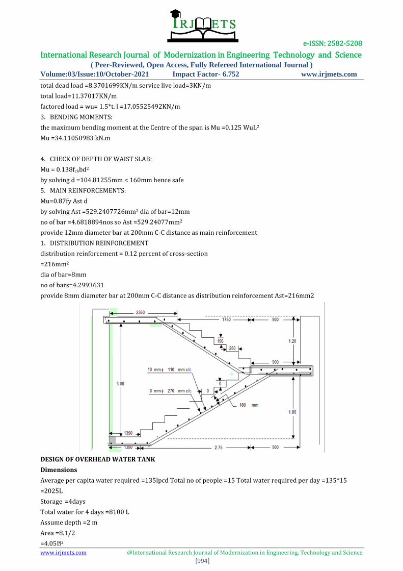
provide 12mm diameter bar at 200mm C-C distance as main reinforcement
1. DISTRIBUTION REINFORCEMENT
distribution reinforcement = 0.12 percent of cross-section
=216mm2
dia of bar=8mm
no of bars=4.2993631
provide 8mm diameter bar at 200mm C-C distance as distribution reinforcement Ast=216mm2
DESIGN OF OVERHEAD WATER TANK
Dimensions
Average per capita water required =135lpcd Total no of people =15 Total water required per day =135*15
=2025L
Storage =4days
Total water for 4 days =8100 L
Assume depth =2 m
Area =8.1/2
=4.05�2

e-ISSN: 2582-5208 International Research Journal of Modernization in Engineering Technology and Science
( Peer-Reviewed, Open Access, Fully Refereed International Journal )
Volume:03/Issue:10/October-2021 Impact Factor- 6.752 www.irjmets.com
www.irjmets.com @International Research Journal of Modernization in Engineering, Technology and Science
[995]
� /� = 3 3*b*b = 4.05
b =1.16 m
l= 3.48
Dimension of overhead tank: 3.48 x 1.16 x 2m
Design of Overhead Tank
Given Capacity of the tank = 8100 litres = 84 m^3 Free board = 0.2 m
Depth of tank = 2 m
Length of tank = 3.48 m
Breadth of tank = 1.16 m Grade of concrete = M25 grade
Permissible Stress cbc = 8.5 N/ /mm2 Modular ratio, M =280/ (3x cbc)= 10.98 ≈ 11
st = 275 N/mm2 for Fe 500 K = (mx cb) / (mx cbcx st) = 0.25373 ≈ 0.254 j = 1- K/3 = 1 – 0.254/3 = 0.915
k = 0.5 x0.314 x n x j = 0.988 N/mm2
Dimensions of Tank Height = 2+ 0.2 = 2.2m (L\B) = 3 m
Maximum Bending Moment at the base of,
Long walls = H 3 /6 = (9.81*2.2^3)/6 = 17.40 kN m
d = M^0.5/(Qb)^0.5 = (17.40*10^6) ^0.5/ (0.988*1000) ^0.5 =132.7mm =133mm
Let us use 12 mm diameter bars and 30 mm nominal cover, Overall depth (D) =169 mm
Effective depth (d) = 133mm
Therefore, Ast =17.40*106 /93.5*0.915*133= 1529.2mm2
Spacing of 12mm bars = (1000*0.25*3.14*12*12)/1529.2 =73.92= 75mm
Let us provide 75mm c/c spacing. The spacing is increased towards the top for 1 m. Intensity of pressure 1 m
above base is, p = 9.81 (2-1) = 9.81 kN/m2
Direct tension in long walls, T = (9.81*B)/2 = (9.81*1.16)/2 = 5.68 kN Ast = (5.68*1000)/100 = 56.8 mm2
Astmin = 0.12bD/100 = 235.248 mm2
Provide 8 mm diameter bars, spacing = (1000*0.25*3.14*8*8)/235.248 =213.5mm Let us provide 250 mm c/c.
Design of Short wall:
p = 9.81 kN/m2
Effective span of horizontal slab = (1.16 + 0.3) = 1.46 m
Bending Moment (Corner Section) = pl^2 /12 = (9.81*1.46^2/12) = 1.74kN m Tension transferred per meter
height of short wall = 9.81*1 = 9.81 kN
Ast = (M-Tx) /st jd + (T)/ st = (1.74*10^6) - (9.81*1000) (133-75) /275*0.915*133
+ (9.81*1000) /275 = 105.83 mm2
Spacing of 8 mm bars = 1000*50.265/ 105.83 = 474.95 mm Adopt 8 mm bars at 300 mm c/c
DESIGN OF UNDERGROUND SUMP
Dimensions
Total water required per day =2025
Storage =2025* 10
=20250 L
Assume depth =1.5 m
Area =13.5m2
𝑙/𝑑 =3
3b2 =13.5
b=2.12m
𝑙 = 3*2.12 = 6.3m Dimensions of underground sump: 6.3x 2.12x 1.5
e-ISSN: 2582-5208 International Research Journal of Modernization in Engineering Technology and Science
( Peer-Reviewed, Open Access, Fully Refereed International Journal )
Volume:03/Issue:10/October-2021 Impact Factor- 6.752 www.irjmets.com
www.irjmets.com @International Research Journal of Modernization in Engineering, Technology and Science
[996]
Design of Sump
Given
Capacity of the tank = 20250 liters
= 20.25m3
Free board = 0.2 m Breadth of tank = 2.12 m Length of tank = 6.3 m Height of tank = 1.5 m
Storage height = 1.5 - 0.2
= 1.3 m
TWO CONDITIONS:
1. Tank Full:
H = 1.3 m Υ = 10 m
M = M = (10 x 1.33) / 6 = 3.66 kNm
T = (10 x 1.3) x 2.12 / 2 = 13.78 kN
For M 20 and Fe 415
Q = 1.16, j = 0.87
M = Qbd2
3.66 x 106 = 1.16 x 1000 x d2
d = 57mm
D = d + cover (30 mm) + (diameter of bar) / 2
= 57 + 30 + 12 / 2 = 93mm
Ast = 3.66 x 10⁶ / 0.87 x 57 x 150 = 492.034 mm2
Using 12mm bars
Spacings: 1000 / Ast x 113.09
= 230mm c/c
Ast (min) = 0.12 x b x D / 100
= 223mm2
Proving 8 mm bars for distribution Spacings: 1000 / (223/ 71.74) = 320mm c/c
Check for Tension (T):
Consider 1 m height of the well, Tensile stress induced = T / area
= 13.78 x 10³ / 1000 x 93 = 0.148 N/mm2 < 1.2 N/mm2
Therefore, safe
2. Tank Empty:
M = Ka x Vsoil x H3 / 6 =
= = 0.3 x 15 x 1.33 / 6 = 1.647
Ast = 492mm2 Using 12 mm bars
Spacing = 1000 x 71.74 / 492= 145.8mm
Provide distribution reinforcement horizontally in both faces @ 140 mm.
Spacing = 2 x 140
= 280 mm
Provide 8 mm bars @ 250 mm
DESIGN OF SEPTIC TANK
Total no of person =15

e-ISSN: 2582-5208 International Research Journal of Modernization in Engineering Technology and Science
( Peer-Reviewed, Open Access, Fully Refereed International Journal )
Volume:03/Issue:10/October-2021 Impact Factor- 6.752 www.irjmets.com
www.irjmets.com @International Research Journal of Modernization in Engineering, Technology and Science
[997]
Average wastewater generated per head =108 L per day (80%) Sludge deposited =40 L per person per year
Cleaning period =1 year
The total volume of wastewater =20*108
=2160 L per day
The capacity of tank required=15*40
=600 L per year
Sludge accommodation:
Detection=2days
The total volume of tank=2x2160+600
=4920L
=4.9cusecs
Assume, 𝑙/𝑑 = 3
Depth =1.5m
Freeboard =0.3m
Area =3.26m2
Breath =1.05m
Length =3.15m
Dimension of septic tank : 3.15m x 1.05m x1.5m
Bar bending schedules COLUMN:
Length of longitudinal bar:
[(3000 + 600 + 1000) – (40 + 16 + 16) + (Ld + 300)]
= 4600 – 72 + [(40 x 25) + 300] = 5828mm
Number of lateral ties:
[Length of longitudinal bar - (Ld + 300) / Spacing] – 1
= [5828 – (40 x 25) + 300 / 300] + 1
= 16 (approximately)
Cutting length of one lateral tie:
2(a+b) + Hook length – bends
Where a = 300 – (2 x 40) – (2 x 8) = 204 mm
b = 300 – (2 x 40) – (2 x 8) = 204 mm
2(204 + 204) + (2 x 10 x 8) – (3 x 2 x 8) = 928 mm (135 deg bend = 10d; 90 deg bend = 2d)
Sr.
No. Type of bar
Dia
(mm) No.
Length
(m)
Total
length (m)
Weight
(kg/m)
Total
weight (kg) Remark
1
Longitudina
l
al bar
25 8 5.828 46.624 3.85 179.5 d*d /
162.2
2 Lateral tie 8 16 0.928 14.828 0.39 5.78 d*d /
162.2
TOTAL 185.28
5%
wastage 9.264
GROSS
WEIGHT 195.544

e-ISSN: 2582-5208 International Research Journal of Modernization in Engineering Technology and Science
( Peer-Reviewed, Open Access, Fully Refereed International Journal )
Volume:03/Issue:10/October-2021 Impact Factor- 6.752 www.irjmets.com
www.irjmets.com @International Research Journal of Modernization in Engineering, Technology and Science
[998]
Column Concrete Nos Length
(m)
Breadth
(m)
Width
(m)
Unit Quality
C1 13 3 0.3 0.3 m3 3.51
C2 13 2.35 0.3 0.3 m3 2.7495
TOTAL 6.2595 m3
FOOTING:
Number of bars along x-axis (Bottom Bar):
𝐵−(2 𝑥 𝐶𝑙𝑒𝑎𝑟 𝑐𝑜𝑣𝑒𝑟) + 1 = 2000− (2 𝑥 40) + 1 = 8 bars
spacing300
Number of bars along y – axis (Top bar):
𝐵−(2 𝑥 𝐶𝑙𝑒𝑎𝑟 𝑐𝑜𝑣𝑒𝑟) + 1 = 2500− (2 𝑥 40) + 1 = 10 bars
spacing 300
Cutting length of bottom bar:
L – (2 x clear cover) + (2 x H) – (4 x clear cover) – Bend deduction= 2500 – (2 x 40) + (2 x 200) – (4 x 40) – (2 x
2 x12) = 2612mm
Cutting length top bar:
B – (2 x clear cover) + (2 x H) – (4 x clear cover) – Bend deduction
= 2000 – (2 x 40) + (2 x 200) – (4 x 40) – (2 x 2 x12) = 2122mm
Sr.
No. Type of bar Dia(mm) No. Length(m)
Total
length(m) Weight(kg)
Total
weight(kg) notes
1 Longitudinal
bar 16mm 8 2.612 20.896 1.58 33.015
256
162
2 Lateral tie 16mm 10 2.122 21.22 1.58 33.52 256
162
Total 66.54
Wastage 1.996
Gross 68.53
SLABS ESTIMATION
S1 = 3.68*3.4
Ly/Lx < 2 therefore it’s a 2-way slab.
Slab size = 3680* 3400*150 mm
Main bar = 10mm dia @150 mm c-c spacing
Distribution bar = 10mm dia @150mm c-c spacing
Development length= 40d
No. of bars in longer span (3680/150) +1 =26 (appx.)
No. of bars in shorter span (3400/150) +1=24(appx.)
Cutting length of main bars in x and y direction
C.L= clear span +2ld+(1*0.42D) –(bent length *2)
=3400 + (2*40*10) + (1*0.42*150) – (10*2)= 4243mm
e-ISSN: 2582-5208 International Research Journal of Modernization in Engineering Technology and Science
( Peer-Reviewed, Open Access, Fully Refereed International Journal )
Volume:03/Issue:10/October-2021 Impact Factor- 6.752 www.irjmets.com
www.irjmets.com @International Research Journal of Modernization in Engineering, Technology and Science
[999]
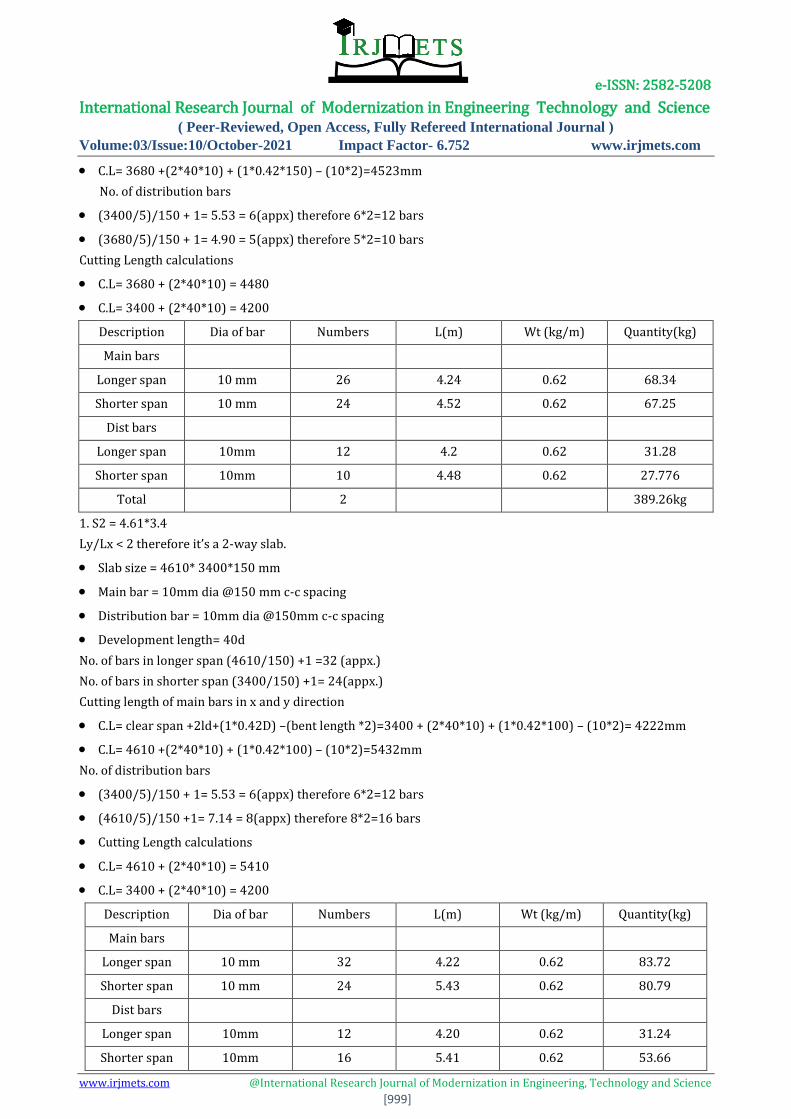
C.L= 3680 +(2*40*10) + (1*0.42*150) – (10*2)=4523mm
No. of distribution bars
(3400/5)/150 + 1= 5.53 = 6(appx) therefore 6*2=12 bars
(3680/5)/150 + 1= 4.90 = 5(appx) therefore 5*2=10 bars
Cutting Length calculations
C.L= 3680 + (2*40*10) = 4480
C.L= 3400 + (2*40*10) = 4200
Description Dia of bar Numbers L(m) Wt (kg/m) Quantity(kg)
Main bars
Longer span 10 mm 26 4.24 0.62 68.34
Shorter span 10 mm 24 4.52 0.62 67.25
Dist bars
Longer span 10mm 12 4.2 0.62 31.28
Shorter span 10mm 10 4.48 0.62 27.776
Total 2 389.26kg
1. S2 = 4.61*3.4
Ly/Lx < 2 therefore it’s a 2-way slab.
Slab size = 4610* 3400*150 mm
Main bar = 10mm dia @150 mm c-c spacing
Distribution bar = 10mm dia @150mm c-c spacing
Development length= 40d
No. of bars in longer span (4610/150) +1 =32 (appx.)
No. of bars in shorter span (3400/150) +1= 24(appx.)
Cutting length of main bars in x and y direction
C.L= clear span +2ld+(1*0.42D) –(bent length *2)=3400 + (2*40*10) + (1*0.42*100) – (10*2)= 4222mm
C.L= 4610 +(2*40*10) + (1*0.42*100) – (10*2)=5432mm
No. of distribution bars
(3400/5)/150 + 1= 5.53 = 6(appx) therefore 6*2=12 bars
(4610/5)/150 +1= 7.14 = 8(appx) therefore 8*2=16 bars
Cutting Length calculations
C.L= 4610 + (2*40*10) = 5410
C.L= 3400 + (2*40*10) = 4200
Description Dia of bar Numbers L(m) Wt (kg/m) Quantity(kg)
Main bars
Longer span 10 mm 32 4.22 0.62 83.72
Shorter span 10 mm 24 5.43 0.62 80.79
Dist bars
Longer span 10mm 12 4.20 0.62 31.24
Shorter span 10mm 16 5.41 0.62 53.66

e-ISSN: 2582-5208 International Research Journal of Modernization in Engineering Technology and Science
( Peer-Reviewed, Open Access, Fully Refereed International Journal )
Volume:03/Issue:10/October-2021 Impact Factor- 6.752 www.irjmets.com
www.irjmets.com @International Research Journal of Modernization in Engineering, Technology and Science
[1000]
Total 2 498.82 kg
2. S3 = 4.61*3.74
Ly/Lx < 2 therefore it’s a 2-way slab.
Slab size = 4610* 3740*150 mm
Main bar = 10mm dia @150 mm c-c spacing
Distribution bar = 10mm dia @150mm c-c spacing
(4610/5)/150 + 1= 4.39= 5(appx) therefore 5*2=10 bars
(2870/5)/150 +1= 4.28 = 5(appx) therefore 5*2=10 bars
Cutting Length calculations
C.L= 2870 + (2*40*10) = 4080
C.L= 4610 + (2*40*10) = 4190
Description Dia of bar Numbers L(m) Wt (kg/m) Quantity(kg)
Main bars
Longer span 10 mm 24 4.10 0.62 61.01
Shorter span 10 mm 23 4.21 0.62 60.03
Dist bars
Longer span 10mm 10 4.08 0.62 25.30
Shorter span 10mm 10 4.19 0.62 25.98
Total 2 344.64 kg
4. S5 = 3.68*3.24
Ly/Lx < 2 therefore it’s a 2-way slab.
Slab size = 3680* 3240*150 mm
Main bar = 10mm dia @150 mm c-c spacing
Distribution bar = 10mm dia @150mm c-c spacing
Development length= 40d
No. of bars in shorter span (3240/150) +1 = 23
No. of bars in longer span
(3680/150) +1= 26
Cutting length of main bars in x and y direction
C.L= clear span +2ld+(1*0.42D) –(bent length *2)=3680 + (2*40*10) + (1*0.42*100) – (10*2)= 4502mm
C.L= 3240 +(2*40*10) + (1*0.42*100) – (10*2)=4062mm
No. of distribution bars
(3680/5)/150 + 1= 5.90= 6(appx) therefore 6*2=12 bars
(3240/5)/150 +1= 5.32= 6(appx) therefore 6*2=12 bars
Cutting Length calculations
C.L= 3680 + (2*40*10) = 4480
C.L= 3240 + (2*40*10) = 4040
Description Dia of bar Numbers L(m) Wt (kg/m) Quantity(kg)
Main bars

e-ISSN: 2582-5208 International Research Journal of Modernization in Engineering Technology and Science
( Peer-Reviewed, Open Access, Fully Refereed International Journal )
Volume:03/Issue:10/October-2021 Impact Factor- 6.752 www.irjmets.com
www.irjmets.com @International Research Journal of Modernization in Engineering, Technology and Science
[1001]
Longer span 10 mm 26 4.062 0.62 65.47
Shorter span 10 mm 23 4.502 0.62 64.19
Dist bars
Longer span 10mm 12 4.04 0.62 30.05
Shorter span 10mm 12 4.48 0.62 33.33
Total 2 386.08 kg
5. S6 = 3.68*3.43
Ly/Lx < 2 therefore it’s a 2-way slab.
Slab size = 3680* 3430*150 mm
Main bar = 10mm dia @150 mm c-c spacing
Distribution bar = 10mm dia @150mm c-c spacing
Development length= 40d
No. of bars in shorter span (3430/150) +1 =24 (appx.)
No. of bars in longer span (3680/150) +1= 26 (appx.)
Cutting length of main bars in x and y direction
C.L= clear span +2ld+(1*0.42D) –(bent length *2)=3430 + (2*40*10) + (1*0.42*100) – (10*2)= 4252mm
C.L= 3680 +(2*40*10) + (1*0.42*100) – (10*2)=4502mm
No. of distribution bars
(3430/5)/150 + 1= 5.57= 6(appx) therefore 6*2=12 bars
(3680/5)/150 +1= 5.90= 6(appx) therefore 6*2=12 bars
Cutting Length calculations
C.L= 3430 + (2*40*10) = 4230;4480
Description Dia of bar Numbers L(m) Wt (kg/m) Quantity(kg)
Main bars
Longer span 10 mm 26 4.252 0.62 68.54
Shorter span 10 mm 24 4.502 0.62 66.98
Dist bars
Longer span 10mm 12 4.23 0.62 31.47
Shorter span 10mm 12 4.48 0.62 33.33
Total 2 400.64 kg
Total weight:
S1 + S2 + S3 + S4 + S5 + S6 = 389.26 + 498.82 + 526.7 + 344.64 + 386.08 + 400.64
= 2546.14 kg = 2.546 tonnes
BEAMS:
Development length= 40d
No. of bars in shorter span (4610/150) +1 =32 (appx.)
No. of bars in longer span (3740/150) +1= 26(appx.)
Cutting length of main bars in x and y-direction
C.L= clear span +2ld+(1*0.42D) –(bent length *2)=4610 + (2*40*10) + (1*0.42*100) – (10*2)= 5432mm
C.L= 3740 +(2*40*10) + (1*0.42*100) – (10*2)=4562mm
e-ISSN: 2582-5208 International Research Journal of Modernization in Engineering Technology and Science
( Peer-Reviewed, Open Access, Fully Refereed International Journal )
Volume:03/Issue:10/October-2021 Impact Factor- 6.752 www.irjmets.com
www.irjmets.com @International Research Journal of Modernization in Engineering, Technology and Science
[1002]
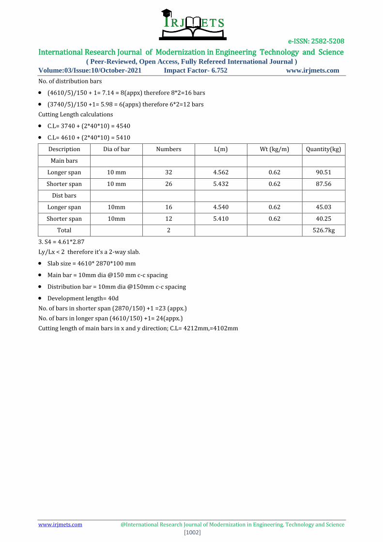
No. of distribution bars
(4610/5)/150 + 1= 7.14 = 8(appx) therefore 8*2=16 bars
(3740/5)/150 +1= 5.98 = 6(appx) therefore 6*2=12 bars
Cutting Length calculations
C.L= 3740 + (2*40*10) = 4540
C.L= 4610 + (2*40*10) = 5410
Description Dia of bar Numbers L(m) Wt (kg/m) Quantity(kg)
Main bars
Longer span 10 mm 32 4.562 0.62 90.51
Shorter span 10 mm 26 5.432 0.62 87.56
Dist bars
Longer span 10mm 16 4.540 0.62 45.03
Shorter span 10mm 12 5.410 0.62 40.25
Total 2 526.7kg
3. S4 = 4.61*2.87
Ly/Lx < 2 therefore it’s a 2-way slab.
Slab size = 4610* 2870*100 mm
Main bar = 10mm dia @150 mm c-c spacing
Distribution bar = 10mm dia @150mm c-c spacing
Development length= 40d
No. of bars in shorter span (2870/150) +1 =23 (appx.)
No. of bars in longer span (4610/150) +1= 24(appx.)
Cutting length of main bars in x and y direction; C.L= 4212mm,=4102mm
e-ISSN: 2582-5208 International Research Journal of Modernization in Engineering Technology and Science
( Peer-Reviewed, Open Access, Fully Refereed International Journal )
Volume:03/Issue:10/October-2021 Impact Factor- 6.752 www.irjmets.com
www.irjmets.com @International Research Journal of Modernization in Engineering, Technology and Science
[1003]
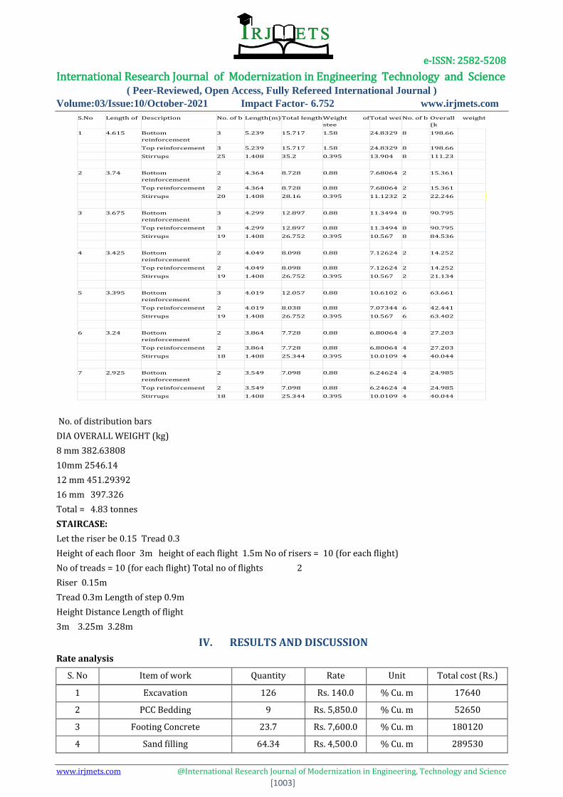
No. of distribution bars
DIA OVERALL WEIGHT (kg)
8 mm 382.63808
10mm 2546.14
12 mm 451.29392
16 mm 397.326
Total = 4.83 tonnes
STAIRCASE:
Let the riser be 0.15 Tread 0.3
Height of each floor 3m height of each flight 1.5m No of risers = 10 (for each flight)
No of treads = 10 (for each flight) Total no of flights 2
Riser 0.15m
Tread 0.3m Length of step 0.9m
Height Distance Length of flight
3m 3.25m 3.28m
IV. RESULTS AND DISCUSSION
Rate analysis
S. No Item of work Quantity Rate Unit Total cost (Rs.)
1 Excavation 126 Rs. 140.0 % Cu. m 17640
2 PCC Bedding 9 Rs. 5,850.0 % Cu. m 52650
3 Footing Concrete 23.7 Rs. 7,600.0 % Cu. m 180120
4 Sand filling 64.34 Rs. 4,500.0 % Cu. m 289530
S.No Length of Description No. of b Length(m) Total length Weight of
stee
Total wei No. of b Overall weight
(k
1 4.615 Bottom
reinforcement
3 5.239 15.717 1.58 24.8329 8 198.66
Top reinforcement 3 5.239 15.717 1.58 24.8329 8 198.66
Stirrups 25 1.408 35.2 0.395 13.904 8 111.23
2 3.74 Bottom
reinforcement
2 4.364 8.728 0.88 7.68064 2 15.361
Top reinforcement 2 4.364 8.728 0.88 7.68064 2 15.361
Stirrups 20 1.408 28.16 0.395 11.1232 2 22.246
3 3.675 Bottom
reinforcement
3 4.299 12.897 0.88 11.3494 8 90.795
Top reinforcement 3 4.299 12.897 0.88 11.3494 8 90.795
Stirrups 19 1.408 26.752 0.395 10.567 8 84.536
4 3.425 Bottom
reinforcement
2 4.049 8.098 0.88 7.12624 2 14.252
Top reinforcement 2 4.049 8.098 0.88 7.12624 2 14.252
Stirrups 19 1.408 26.752 0.395 10.567 2 21.134
5 3.395 Bottom
reinforcement
3 4.019 12.057 0.88 10.6102 6 63.661
Top reinforcement 2 4.019 8.038 0.88 7.07344 6 42.441
Stirrups 19 1.408 26.752 0.395 10.567 6 63.402
6 3.24 Bottom
reinforcement
2 3.864 7.728 0.88 6.80064 4 27.203
Top reinforcement 2 3.864 7.728 0.88 6.80064 4 27.203
Stirrups 18 1.408 25.344 0.395 10.0109 4 40.044
7 2.925 Bottom
reinforcement
2 3.549 7.098 0.88 6.24624 4 24.985
Top reinforcement 2 3.549 7.098 0.88 6.24624 4 24.985
Stirrups 18 1.408 25.344 0.395 10.0109 4 40.044

e-ISSN: 2582-5208 International Research Journal of Modernization in Engineering Technology and Science
( Peer-Reviewed, Open Access, Fully Refereed International Journal )
Volume:03/Issue:10/October-2021 Impact Factor- 6.752 www.irjmets.com
www.irjmets.com @International Research Journal of Modernization in Engineering, Technology and Science
[1004]
5 RCC works 54.25685358 Rs. 8,800.0 % Cu. m 477460.3115
6 Reinforcing steel
8 mm 2.02402458 Rs. 50,000.0 % Tonne 101201.229
10 mm 3.898251 Rs. 50,000.0 % Tonne 194912.55
12 mm 0.042326508 Rs.50,000.0 % Tonne 2116.3254
16 mm 5.08581008 Rs.50,000.0 % Tonne 254290.504
20 mm 5.44077 Rs.48,000.0 % Tonne 261156.96
7 Brickwork 115616.2697 Rs. 8.0 Piece 924930.1572
8 Labor for Brick-laying 220.221466 Rs. 920.0 % Cu. m 202603.7487
9 Damp Proof Course
(50 mm thick) 123.4686 Rs. 325.0 % Sq. m 40127.295
10 Flooring Concrete 18.52029 Rs. 5,850.0 % Sq. m 108343.6965
11 Tile flooring 268.9078 Rs. 1,700.0 % Sq. m 457143.26
13 Rooftop area 101.498 Rs. 600.0 % Sq. m 60898.8
14 Wall plastering 1116.928 Rs.190.0 % Sq. m 212216.32
15 Ceiling plastering 268.9078 Rs. 190.0 % Sq. m 51092.482
16 Ceiling Whitewash 806.7234 Rs. 8.0 % Sq. m 6453.7872
17 Whitewash 3350.784 Rs. 8.0 % Sq. m 26806.272
18 Colour wash 2233.856 Rs. 10.0 % Sq. m 22338.56
19 Doors
Wooden doors 6.174 Rs. 6,800.0 % Sq. m 41983.2
PVC Doors 5 Rs.2,000.0 Numbers 10000
20 Windows 21 Rs. 2,800.0 Numbers 58800
21 Ventilators 2.7755 Rs. 700.0 % Sq. m 1942.85
Total cost 2486837.389
Sanitary fixtures (10%) 248683.7389
Electrical fixtures(8%) 198946.9911
Contingency (3%) 74605.12166
Supervision (8%) 198946.9911
Net total Rs. 32,08,020.23
V. CONCLUSION
• The number of beams were 36 in number
• The number of slabs were 12 in number
• The number of columns were 26 in number
• The number of footings is 13 in number
• Cost estimation analysis of the project was worked out and the final cost projected was � 32,08,020.23
• Total reinforcement steel was estimated to be 16.491182 tons
• Total concrete quantity was estimated to be 54.25685358 m3

e-ISSN: 2582-5208 International Research Journal of Modernization in Engineering Technology and Science
( Peer-Reviewed, Open Access, Fully Refereed International Journal )
Volume :03/Issue :09/September-2021 Impact Factor- 6.752
www.irjmets.com
www.irjmets.com @International Research Journal of Modernization in Engineering, Technology, and Science
[1005]
VI. REFERENCES
[1] SP 7: 2016 - National Building Code of India, Bureau of Indian Standards, New Delhi.
[2] IS 456: 2016 - Plain and Reinforced concrete - Code of practice, Bureau of Indian Standards, New Delhi.
[3] SP 16: 1980 - Design aids for Reinforced concrete to IS 456, Bureau of Indian Standards, New Delhi.
[4] IS 875 (Part 1): 2018 - Dead Loads - Code of Practice for Design loads (Other than Earthquake) for
Buildings and Structures, Bureau of Indian Standards, New Delhi.
[5] IS 875 (Part 2): 2018 - Imposed Loads - Code of Practice for Design loads (Other than Earthquake) for
Buildings and Structures, Bureau of Indian Standards, New Delhi.
[6] IS 1893 (Part 1): 2016 - General provisions and buildings - Criteria for Earthquake resistant design of
structures, Bureau of Indian Standards, New Delhi.
[7] IS 13920: 2016 - Ductile design and detailing of Reinforced concrete structures subjected to seismic
forces - Code of practice, Bureau of Indian Standards, New Delhi.
[8] SP 34: 1987 - Handbook on Concrete reinforcement and detailing, Bureau of Indian Standards, New
Delhi.