g7 acetabular system - zimmerbiomet.com · e1 ® and arcomxl ... the g7 acetabular system utilizes...
TRANSCRIPT

G7®AcetabularSystem
Surgical Technique


Table of Contents
Quick Reference Guides ........................................................................................... 2
Device Description .................................................................................................... 8
Preoperative Templating .......................................................................................... 9
Patient Positioning ................................................................................................. 10
Acetabular Exposure .............................................................................................. 10
Acetabular Reaming ............................................................................................... 11
Optional Shell Trialing and Alignment .................................................................... 12 Inserter Handle Assembly.................................................................................. 13 Optional Shell Trialing with Inserter Handle ....................................................... 14 Optional Shell Trialing Alignment with Positioning Guides ................................. 15
Liner Trialing with Provisional Shell........................................................................ 17
Trial Reduction and Range of Motion ..................................................................... 18
Acetabular Shell Insertion ...................................................................................... 19
Supplemental Screw Fixation ................................................................................. 23
Optional Liner Trialing with Final Implant .............................................................. 25
Optional Apical Plug ............................................................................................... 26
Polyethylene Liner Insertion ................................................................................... 26
Modular Head Selection and Impaction ................................................................. 28
Final Reduction ....................................................................................................... 28
Polyethylene Liner Removal ................................................................................... 29
Primary Shell Removal ............................................................................................ 32
Straight and Curved Inserter Handle Disassembly ................................................ 33
Indications and Contraindications ......................................................................... 34

2 | G7 Acetabular System Surgical Technique
Step 7:Liner Trialing
Step 3:Instrument Selection
Step 8:Liner Insertion
Step 9:Final Reduction
Step 4:Shell Trialing (optional)
Step 5:Shell Insertion
Step 6:Supplemental Screw Insertion (optional)
Step 2:Reaming
Note: There may be slight variations in colors between components.
Step 1:Preoperative Planning
OrthoSize.com
Quick Reference Surgical Technique

3 | G7 Acetabular System Surgical Technique
Acetabular Shells
OsseoTi®* Limited and Multi Hole
PPS® and BoneMaster™* Limited Hole
Finned PPS and BoneMaster* Limited Hole
Neutral +5 Neutral
High Wall 10 Degree Face Changing
E1® and ArComXL® Polyethylene
Dual Mobility(CoCr only)
Dual Mobility Bearing(E1 & ArCom XL)
Dual Mobility*
BIOLOX® delta
Ceramic*
+5 Neutral 10 Degree Face Changing
E1 Freedom® Constrained Polyethylene
Neutral
CoCr Modular Freedom CoCrBIOLOX® delta BIOLOX® delta Option
Liners
Femoral Heads
* Not for sale in the US.

4 | G7 Acetabular System Surgical Technique
Quick Reference Polyethylene Guide
* Available in OsseoTi Multi Hole configuration only
Polyethylene Articulation Sizing(Neutral, High Wall, 10 Degree Face Changing & +5 mm Liners)
10 Degree Face Changing Leg Length Chart
Shell Size (mm)
Head Size (mm)
28 32 36 40 44
42A 28
44
46 B 28 32
48 C 28 32
50 D 28 32 36
52 E 28 32 36
54F 28 32 36 40
56
58G 28 32 36 40
60
62H 32 36 40 44
64
66
I 36 40 4468
70*
72*
74
J* 36 40 4476
78
80
Shell Size (mm)
Offset (mm)
Leg Length (mm)
Lateralization (mm)
42A 3.2 2.4 2.1
44
46 B 3.6 2.7 2.3
48 C 3.7 2.8 2.4
50 D 3.9 3 2.6
52 E 4.1 3.1 2.7
54F 4.3 3.2 2.8
56
58G 4.4 3.4 2.9
60
62H 4.8 3.6 3.1
64
66
I 5.1 3.9 3.368
70*
72*
74
J* 5.7 4.3 3.776
78
80

5 | G7 Acetabular System Surgical Technique
Quick Reference Polyethylene Thickness Guide
45°
Apex
* Available in OsseoTi Multi Hole configuration only
≈ Minimum Poly Liner Thickness at Apex (mm)(Neutral, High Wall, 10 Degree Face Changing & Freedom Constrained Liners)
Shell Size (mm)
Head Size (mm)
28 32 36 40 44
42A 4.7
44
46 B 6.7 4.7
48 C 7.7 5.7
50 D 8.7 6.7 4.7
52 E 9.7 7.7 5.7
54F 10.7 8.7 6.7 4.7
56
58G 11.7 9.7 7.7 5.7
6062
H 11.7 9.7 7.7 5.764
68
I 11.7 9.7 7.768
70*
72*
74
J* 14.7 12.7 10.776
75
80
≈ Minimum Poly Liner Thickness at 45° (mm)(Neutral, High Wall, 10 Degree FaceChanging & Freedom Constrained Liners)
Shell Size (mm)
Head Size (mm)
28 32 36 40 44
42A 4.3
44
46 B 6.3 4.3
48 C 7.3 5.3
50 D 8.3 6.3 4.3
52 E 9.3 7.3 5.3
54F 10.3 8.3 6.3 4.3
56
58G 11.3 9.3 7.3 5.3
60
62H 11.3 9.3 7.3 5.3
64
66
I 11.3 9.3 7.368
70*
72*
74
J* 14.3 12.3 10.376
78
80

6 | G7 Acetabular System Surgical Technique
Quick Reference Polyethylene Thickness Guide
≈ +5 Poly Liner Thickness at Apex (mm)
Shell Size (mm)
Head Size (mm)
28 32 36 40 44
42A 9.7
44
46 B 11.7 9.7
48 C 12.7 10.7
50 D 13.7 11.7 9.7
52 E 14.7 12.7 10.7
54F 15.7 13.7 11.7 9.7
56
58G 16.7 14.7 12.7 10.7
6062
H 16.7 14.7 12.7 10.764
68
I 18.7 16.7 14.7 12.768
70*
72*
74
J* 19.7 17.7 15.776
75
80
≈ +5 Poly Liner Thickness at 45° (mm)
Shell Size (mm)
Head Size (mm)
28 32 36 40 44
42A 7.4
44
46 B 9.4 7.4
48 C 10.4 8.4
50 D 11.4 9.4 7.4
52 E 12.4 10.4 8.4
54F 13.4 11.4 9.4 7.4
56
58G 14.4 12.4 10.4 8.4
60
62H 14.4 12.4 10.4 8.4
64
66
I 16.4 14.4 12.4 10.468
70*
72*
74
J* 17.4 15.4 13.476
78
80
* Available in OsseoTi Multi Hole configuration only
45°
Apex

7 | G7 Acetabular System Surgical Technique
Freedom Constrained Sizing Chart
Shell Size (mm)
Head Size (mm)
28 32 36
42A
44
46 B 32
48 C 32
50 D 36
52 E 36
54F 36
56
58G 36
6062
H 3664
68
I 3668
70*
72*
74
J* 3676
75
80
* Available in OsseoTi Multi Hole configuration only
Quick Reference Polyethylene Thickness Guide

8 | G7 Acetabular System Surgical Technique
Device DescriptionThe hemispherical design of the G7 acetabular shell provides fixation and stability with proven1–7 PPS Porous Plasma Spray Coating or OsseoTi Porous Structure. Multiple bearing options are also available, including E1 Antioxidant Infused Technology and ArComXL Polyethylene.
The G7 Acetabular System utilizes a unique color coding system designed to offer an efficient operating experience. The provisional shells, provisional liners, labels and face plate impactors match the color anodized on the rim and letter designation of the acetabular shell implant (Figure 1).
The G7 Acetabular System color and letter coding key is listed in Figure 2.
Note: Implant identification should be made using letter and size information. Color coding should be used only as a secondary reference. There may be slight variations in colors between components.
Figure 1 Figure 2
G7 Acetabular System Color & Letter Coding Key
Color and Liner Size
Shell Size(s) (mm)
A 42,44
B 46
C 48
D 50
E 52
F 54,56
G 58,60
H 62,64
I 66, 68, 70*, 72*
J* 74, 76, 78, 80
*Available in OsseoTi Multi Hole configuration only
Surgical Technique

9 | G7 Acetabular System Surgical Technique
Preoperative TemplatingAccurate preoperative planning and acetabular templating help determine the size, desired location and position of the acetabular shell and are an essential part of the surgical process. Templating is best performed with an A/P pelvis radiograph with the limb internally rotated approximately 15 degrees. This allows more accurate determination of femoral offset, radiographic leg length inequality, and referencing of contralateral hip, if required.
When examining the A/P radiograph, the shell should be positioned against, but not medial to, the radiographic teardrop at 40 degrees of inclination. Acetabular shell size is best determined on a cross-table lateral radiograph. If the patient’s anatomy is obscured, it may be helpful to check the acetabular component size on the contralateral hip radiograph, as well.
Make note of the shell size that fills the acetabular space appropriately and fits the anterior to posterior diameter of the native acetabulum, keeping in mind that final decision on shell size should be made during surgery when adequate visualization of the acetabulum is achieved.
Note: Use of an X-ray magnification marker is needed to template with OrthoSize® Digital Templating Software. The magnification marker can be located against the joint (ball/coin) or on the table (coin/ruler), but must be visible within the X-ray.
OrthoSize.com

10 | G7 Acetabular System Surgical Technique
Figure 3
Patient PositioningPatient position should be determined by surgeon’s preferred approach (Figure 3).
Acetabular ExposurePrior to reaming, acetabular exposure should be adequate and the anterior, posterior and superior walls should be directly visible. The medial acetabular wall, which dictates the depth of the reaming, should be uncovered of floor osteophytes or pulvinar pad. Specialized acetabular retractors are available to help facilitate exposure for whichever approach is chosen.

11 | G7 Acetabular System Surgical Technique
Acetabular ReamingDetermine a starting reamer size from the preoperative template and from the measured diameter of the resected femoral head. This is typically 6–8 mm smaller than the femoral head diameter. Reamer handles are provided as straight or curved (offset). Use is dictated by surgeon preference, surgical exposure, and patient body composition. During the reaming process, frequently determine the amount of anterior and posterior acetabular bone remaining to avoid reaming away the wall and compromising fixation.
Beginning with a small reamer, apply constant pressure first toward the medial wall, appropriately medializing the acetabulum for optimal hip biomechanics and the normal center of hip rotation. Gradually progress to larger reamers, while maintaining concentricity within the acetabular cavity until bleeding subchondral bone is exposed (Figure 4).
The preferred acetabular orientation is 40 degrees inclination and 20 degrees of anteversion, but final acetabular position depends on patient anatomy and may vary slightly with approach. Final orientation of the acetabular implant is also dictated by the amount of version of the femoral implant (i.e., greater anteversion of the acetabular component may be required in the case of a retroverted stem). Under-reaming of the acetabulum is dependent on bone quality and should be determined by the surgeon intraoperatively as soft bone will more readily accommodate a larger press-fit than harder, sclerotic bone. The following reaming recommendation may be used as an initial guideline:
Figure 4
Acetabular Shell
Recommended Under-Ream*
G7 PPS and OsseoTi Hemispherical Shell
1 mm under final implant size
G7 Finned Hemispherical Shell
Line to line
* This is a general recommendation only, appropriate reaming is dependent on bone quality and should be determined by the surgeon intraoperatively.

12 | G7 Acetabular System Surgical Technique
Acetabular Reaming (cont.)
Once reaming is complete, use the provisional shells to confirm the position and accuracy of the reaming. Final shaping must be achieved using the hemispherical grater reamer to ensure a congruent fit between the shell and the acetabulum.
Note: All G7 acetabular shells are measured over porous coating or structure. All acetabular shells, provisional shells and acetabular reamers are marked true to size. All components are a full hemisphere and measure 180 degrees (Figure 5).
Figure 5
Optional Shell Trialing and Alignment Once the desired ream has been achieved, select a provisional shell that is 1 mm smaller than the final implant. The provisional shell is marked with its true size and indicates the corresponding liner size both alphabetically and by color (Figure 6).
The shell gauge handle may be threaded to the acetabular shell provisional and used to gauge the size of the reamed acetabulum (Figure 6).
Note: Do not impact on the shell gauge handle.
Alternatively, utilize either the straight monoblock, curved or straight modular inserter handle. Place the provisional shell into the acetabulum at approximately 40 degrees of inclination and 20 degrees of anteversion.
Figure 6
47 mm
180°
47 mm
180°
48 mm
180°

13 | G7 Acetabular System Surgical Technique
Inserter Handle Assembly
When using the curved or straight modular handle, place the appropriate threaded shaft into the handle through the hole in the strike plate of the straight modular handle (Figures 7 and 8), or the hole at the distal tip of the curved inserter handle (Figure 9).
If using the G7 Straight Monoblock Inserter Handle, assemble to the mating component by rotating clockwise and disassemble by rotating counter-clockwise. Ensure the G7 Monoblock Inserter Handle is fully threaded to the mating component prior to impaction.
Note: Levering on the inserter handle or impacting the handle on a location other than the strike plate to reposition the shell may damage the threads.
Figure 8 Figure 9Figure 7

14 | G7 Acetabular System Surgical Technique
Optional Shell Trialing with Inserter Handle
Insert the ball hex driver into the hole in the strike plate of the straight handle or the hole at the distal tip of the curved handle and turn to advance the threaded shaft until the threads are exposed (Figures 10 and 11).
Line up the square tip of the insertion handle with the square at the apex of the shell trial. Turn the ball hex driver in a clockwise direction to advance the thread into the shell (Figures 10–12). Remove the ball hex driver from the handle. Ensure that the shell is securely fastened to the handle by lightly pulling on the provisional shell.
Approximate version can be obtained by using the transverse acetabular ligament or by referencing the opening of the acetabular component 90 degrees off of the sciatic notch. Alternatively, a positioning guide may be used.
If using the G7 Straight Monoblock Inserter Handle, assemble to the mating component by rotating clockwise and disassemble by rotating counter-clockwise. Ensure the G7 Monoblock Inserter Handle is fully threaded to the mating component prior to impaction.
Note: Levering on the inserter handle or impacting the handle on a location other than the strike plate to reposition the shell may damage the threads.
Figure 11 Figure 12Figure 10

15 | G7 Acetabular System Surgical Technique
Optional Shell Trialing Alignment with Positioning Guides
The Lateral and Anterior Supine G7 positioning guides are designed to aid in proper insertion of the acetabular component.
Assemble the positioning guide on the back table before securing to the insertion handle. Connect the body of the positioning guide to the insertion handle by sliding the guide into the opening between the handle grip and shaft. Slide the positioning guide into the flat opening on the guide body. When the guide is in place, tighten the positioning guide rod to secure the guide to the handle (Figure 13).
Lateral Guide
When positioning the acetabular shell, the lateral guide arms should be parallel to the table, aimed toward the patient’s ipsilateral shoulder (Figure 14).
For the right hip, use the reference arm of the “V” shaped guide labeled “RIGHT.” For the left hip, use the reference arm of the “V” shaped guide labeled “LEFT” (Figure 13).
Figure 13 Figure 14
16 | G7 Acetabular System Surgical Technique
Optional Shell Trialing Alignment with Positioning Guides (cont.)
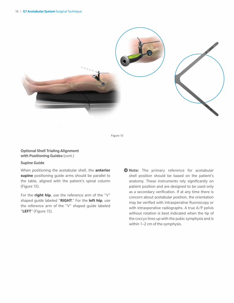
Supine Guide
When positioning the acetabular shell, the anterior supine positioning guide arms should be parallel to the table, aligned with the patient’s spinal column (Figure 15).
For the right hip, use the reference arm of the “V” shaped guide labeled “RIGHT.” For the left hip, use the reference arm of the “V” shaped guide labeled “LEFT” (Figure 15).
Note: The primary reference for acetabular shell position should be based on the patient’s anatomy. These instruments rely significantly on patient position and are designed to be used only as a secondary verification. If at any time there is concern about acetabular position, the orientation may be verified with intraoperative fluoroscopy or with intraoperative radiographs. A true A/P pelvis without rotation is best indicated when the tip of the coccyx lines up with the pubic symphysis and is within 1–2 cm of the symphysis.
Figure 15

17 | G7 Acetabular System Surgical Technique
Lightly impact the provisional shell and confirm complete seating through the cutouts on the provisional shell (Figure 16). Remove any soft tissue or osteophytes from the acetabular rim that overhang the edge of the provisional component to obtain proper seating. If the provisional shell is unstable, or if there are gaps between the provisional shell and the acetabulum, it may be necessary to increase the diameter of the final reamer. However, in some instances it may not be possible to increase the reamed diameter. If this is the case, then supplementary screw fixation may be necessary. Disconnect the inserter handle from the provisional shell.
Liner Trialing with Provisional ShellFollowing seating of the provisional shell, select the appropriate provisional liner size, as indicated alphabetically and by color, in the desired liner configuration.
Insert the provisional liner into the shell by hand. Utilize a 3.5 mm hex screwdriver to tighten the screw in the dome of the provisional liner into the apical hole of the provisional shell (Figure 17).
Note: Do not overtighten the provisional liner.
Figure 16 Figure 17

18 | G7 Acetabular System Surgical Technique
Trial Reduction and Range of MotionSelect the appropriate provisional head, head diameter and neck length to create equal leg length and needed lateralization as determined by the surgeon. These determinations can be made during preoperative templating, but final adjustments are made intraoperatively. Insert the provisional head onto the implanted stem or broach and reduce the hip (Figures 18 and 19).
Ensure the provisional head is seated fully on the trunnion. If using the G7 self retaining provisional head in combination with a Type 1 reduced taper, a click is felt and/or heard when the provisional head is fully seated. Check for joint stability and range of motion, making any necessary adjustments to restore joint mechanics. Make certain that prominent impinging bone and/or osteophytes are removed from the periphery of the acetabulum to maximize range of motion and stability. Make note of all provisional components used and then remove all provisionals.
Figure 19Figure 18

19 | G7 Acetabular System Surgical Technique
Acetabular Shell InsertionSimilar to provisional shell insertion, the same curved or straight handle may be used for the final implant shell insertion (Figure 20).
Note: Limited hole shells are packaged with the screw holes pre-plugged. Should screw fixation be necessary, the screw hole covers should be removed using a 3.5 mm hex driver prior to shell insertion.
Figure 20
When using the curved or straight handle, place the appropriate threaded shaft (Figures 21 and 22) into the handle through the hole in the strike plate of the straight handle, or the hole at the distal tip of the curved handle inserter. For the curved handle, turn clockwise to advance the threads of the internal shaft through the tip of the impactor handle.
If using the G7 Straight Monoblock Inserter Handle, assemble to the mating component by rotating clockwise and disassemble by rotating counter-clockwise. Ensure the G7 Monoblock Inserter Handle is fully threaded to the mating component prior to impaction.
Figure 22
Figure 21

20 | G7 Acetabular System Surgical Technique
Acetabular Shell Insertion (cont.)
Insert the ball hex driver into the hole in the strike plate of the straight handle or the hole at the distal tip of the curved handle and turn to advance the threaded shaft until the threads are exposed. Line up the square tip of the insertion handle with the square indentation on the inside of the G7 shell (Figure 23). Turn the ball hex driver in a clockwise direction to advance the thread into the shell (Figure 24).
Note: If the threads begin to loosen when impacting the modular inserter handle, utilize the ball hex driver to retighten and continue impaction.
Figure 23
Remove the ball hex driver from the handle.
Note: When the curved handle is used, the curve of the insertion handle should line up with the screw holes on the shell. Ensure the shell is securely fastened to the handle by lightly pulling on the shell.
Figure 24
21 | G7 Acetabular System Surgical Technique
Acetabular Shell Insertion (cont.)
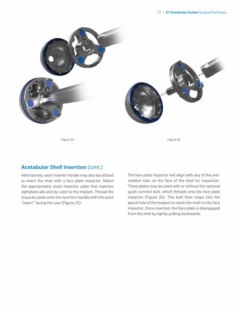
Alternatively, each inserter handle may also be utilized to insert the shell with a face plate impactor. Select the appropriately sized impactor plate that matches alphabetically and by color to the implant. Thread the impactor plate onto the insertion handle with the word “insert” facing the user (Figure 25).
The face plate impactor will align with any of the anti-rotation tabs on the face of the shell for impaction. These plates may be used with or without the optional quick connect bolt, which threads onto the face plate impactor (Figure 26). This bolt then snaps into the apical hole of the implant to retain the shell on the face impactor. Once inserted, the face plate is disengaged from the shell by lightly pulling backwards.
Figure 25 Figure 26
22 | G7 Acetabular System Surgical Technique
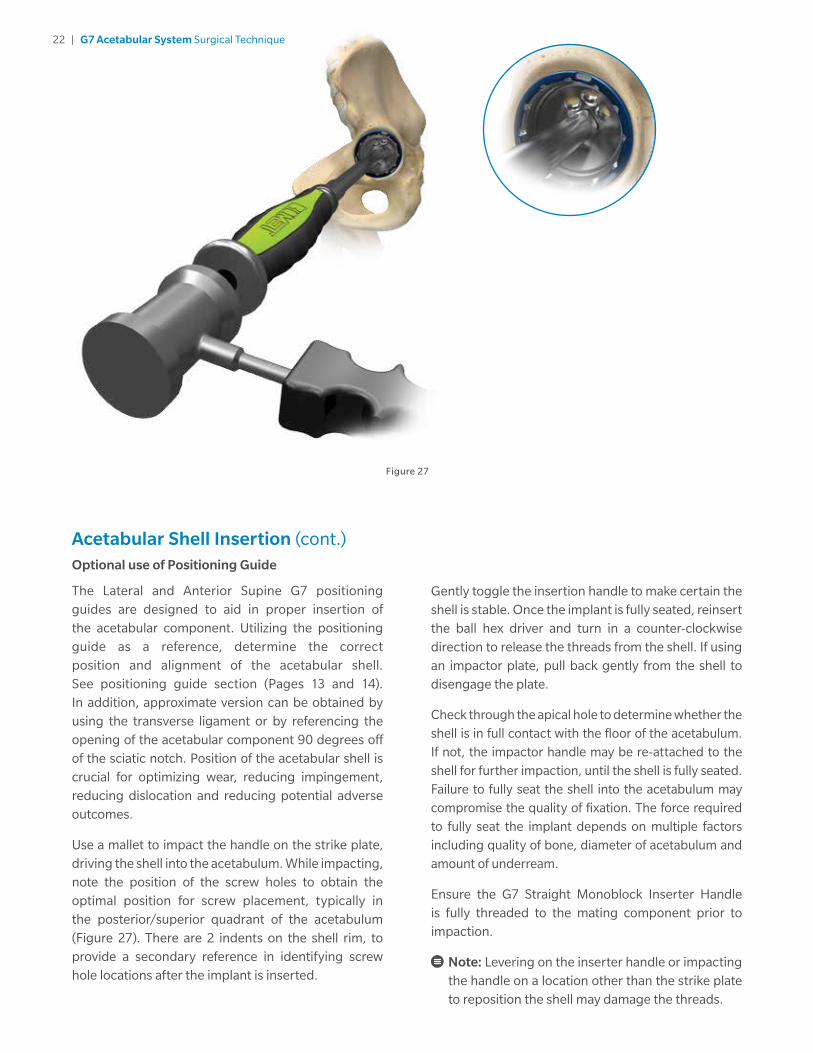
Acetabular Shell Insertion (cont.)Optional use of Positioning Guide
The Lateral and Anterior Supine G7 positioning guides are designed to aid in proper insertion of the acetabular component. Utilizing the positioning guide as a reference, determine the correct position and alignment of the acetabular shell. See positioning guide section (Pages 13 and 14). In addition, approximate version can be obtained by using the transverse ligament or by referencing the opening of the acetabular component 90 degrees off of the sciatic notch. Position of the acetabular shell is crucial for optimizing wear, reducing impingement, reducing dislocation and reducing potential adverse outcomes.
Use a mallet to impact the handle on the strike plate, driving the shell into the acetabulum. While impacting, note the position of the screw holes to obtain the optimal position for screw placement, typically in the posterior/superior quadrant of the acetabulum (Figure 27). There are 2 indents on the shell rim, to provide a secondary reference in identifying screw hole locations after the implant is inserted.
Gently toggle the insertion handle to make certain the shell is stable. Once the implant is fully seated, reinsert the ball hex driver and turn in a counter-clockwise direction to release the threads from the shell. If using an impactor plate, pull back gently from the shell to disengage the plate.
Check through the apical hole to determine whether the shell is in full contact with the floor of the acetabulum. If not, the impactor handle may be re-attached to the shell for further impaction, until the shell is fully seated. Failure to fully seat the shell into the acetabulum may compromise the quality of fixation. The force required to fully seat the implant depends on multiple factors including quality of bone, diameter of acetabulum and amount of underream.
Ensure the G7 Straight Monoblock Inserter Handle is fully threaded to the mating component prior to impaction.
Note: Levering on the inserter handle or impacting the handle on a location other than the strike plate to reposition the shell may damage the threads.
Figure 27

23 | G7 Acetabular System Surgical Technique
Multi hole configurationLimited hole configuration
Acetabular Shell Insertion (cont.)
Note: Consideration should be given to the location of screw holes prior to impaction if screws will be used.
Note: In the unlikely event that the inserter handle threads fracture during impaction and are left in the apical hole of the acetabular shell, utilize the Thread Extractor instrument for removal. The tapered tip of the Thread Extractor may be engaged in the small through hole of the fractured threads, allowing the fractured threads to be removed from the apical hole of the acetabular shell (Figure 28).
Supplemental Screw FixationFor primary cases where good bone stock is present and the shell is firmly seated within the acetabulum, the use of fixation screws is generally unnecessary. However, in cases where press-fit stability is in question, or where the bone quality is not optimal, supplementary screw fixation is advised.
Screw placement must be chosen carefully to avoid injury to neurovascular structures. Optimal position for screw placement is typically in the posterior/superior quadrant of the acetabulum (Figure 29 and 30). Care should also be exercised when supplementary screw fixation is required to avoid damaging or scratching the internal surfaces of the acetabular components. Use of the gold drill guide is required for accurate screw placement. Consideration should be given to placement of a screw near the dome of the implant first to prevent possible shifting of the implant caused when placing peripheral screws.
Note: Placement of screws outside of the “safe zone” may inadvertently injure neurovascular structures and should be utilized at the discretion of the operating surgeon. When using G7 Limited Hole shells, screws should never be placed in the anterior/medial area of the acetabulum. When using the G7 OsseoTi Multi Hole shell, extreme caution should be used if screw placement is required in the anterior/medial area of the acetabulum.
Figure 29 Figure 30Figure 28

24 | G7 Acetabular System Surgical Technique
Supplemental Screw Fixation (cont.)
Use the gold drill guide to drill a pilot hole in the desired screw hole. Make certain the drill guide is fully seated and locked into position within the screw hole BEFORE the drill bit begins to engage bone (Figure 31). This will ensure the appropriate screw direction can be achieved. The G7 screw holes allow approximately 15 degrees of variability. Screws oriented outside this range may result in incomplete seating of the screws and prominent screw heads within the shell, which could impede insertion of the liner. When drilling into the posterior/superior quadrant, place a finger posteriorly into the sciatic notch to ensure the screw cannot penetrate too deeply.
Note: Levering on the drill bit during drilling may cause damage to the drill bit.
Note: Use only the G7 gold colored screws, Zimmer self-tapping bone screws and the gold colored drill guide with the G7 implants.
Note: Check that all screw heads are seated below the inner surface of the shell to ensure proper liner seating.
The drill bits are available in variable lengths. However, 30 or 40 mm drill bits are most commonly utilized. The drill bit chosen should be dictated by surgeon choice and the projected length of the screws. To ensure proper seating of the acetabular screw after drilling pilot holes, it is important to remove all bone debris from the screw hole prior to placing the screw. After measuring the depth of the hole with the depth gauge (Figure 32), select the 6.5 mm gold colored screw or Zimmer self-tapping bone screw with the corresponding length and insert it into the hole with the 3.5 mm hex screwdriver and screw forceps (Figure 33). Place additional screws as needed. Screws should not be placed in the apical hole of the shell.
Figure 31 Figure 33Figure 32

25 | G7 Acetabular System Surgical Technique
Optional Liner Trialing with Final ImplantClean and dry the shell and clear all soft tissue from around its perimeter. If another trial reduction is desired, utilize the provisional liner colored to match the rim of the shell and previously selected during the earlier trial reduction with the matching letter designation. Insert the provisional liner into the shell by hand. Utilizing a 3.5 mm hex screwdriver, tighten the screw in the dome of the provisional liner into the apical hole of the final implant (Figure 34).
Note: Do not overtighten the provisional liner.
Note: For ease of insertion, ensure the screw in the dome of the liner provisional is aligned with the apical hole of the final implant.
Insert a provisional head onto the femoral stem and perform the trial reduction (Figure 35). When selection of the appropriate liner is complete, remove all provisional components.
Note: G7 provisional heads are designed with a retaining feature. A click is felt and/or heard when the provisional head is fully seated.
When using a High Wall or 10 Degree Face Changing liner, note the position of the liner to maintain orientation during final seating or adjust rotation as necessary in order to minimize impingement and optimize stability.
Freedom Constrained Liner Trialing
Determine the desired neck length and head size and select the appropriate provisional head. Insert the provisional head onto the implanted stem or broach. Ensure the provisional head is seated fully on the trunnion and reduce the hip. Check for joint stability and range of motion, making any necessary adjustments to restore joint mechanics. Make certain that prominent impinging bone and/or osteophytes are removed from the periphery of the acetabulum to maximize range of motion and stability. Make note of all provisional components used and then remove all provisionals.
Note: Only Freedom provisional heads are compatible for trialing with Freedom implant liners.
Figure 34 Figure 35
26 | G7 Acetabular System Surgical Technique
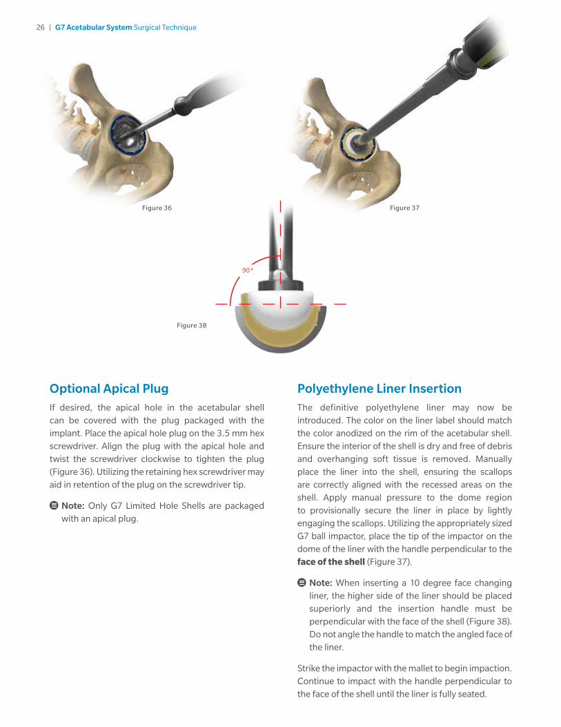
Optional Apical PlugIf desired, the apical hole in the acetabular shell can be covered with the plug packaged with the implant. Place the apical hole plug on the 3.5 mm hex screwdriver. Align the plug with the apical hole and twist the screwdriver clockwise to tighten the plug (Figure 36). Utilizing the retaining hex screwdriver may aid in retention of the plug on the screwdriver tip.
Note: Only G7 Limited Hole Shells are packaged with an apical plug.
Figure 36
Polyethylene Liner Insertion The definitive polyethylene liner may now be introduced. The color on the liner label should match the color anodized on the rim of the acetabular shell. Ensure the interior of the shell is dry and free of debris and overhanging soft tissue is removed. Manually place the liner into the shell, ensuring the scallops are correctly aligned with the recessed areas on the shell. Apply manual pressure to the dome region to provisionally secure the liner in place by lightly engaging the scallops. Utilizing the appropriately sized G7 ball impactor, place the tip of the impactor on the dome of the liner with the handle perpendicular to the face of the shell (Figure 37).
Note: When inserting a 10 degree face changing liner, the higher side of the liner should be placed superiorly and the insertion handle must be perpendicular with the face of the shell (Figure 38). Do not angle the handle to match the angled face of the liner.
Strike the impactor with the mallet to begin impaction. Continue to impact with the handle perpendicular to the face of the shell until the liner is fully seated.
Figure 37
90˚
Figure 38

27 | G7 Acetabular System Surgical Technique
Freedom Constrained Liner Insertion
Remove the black plug covering the mouth of the liner with the Freedom plug removal tool (Figure 40); discard this plug. Place the liner into the acetabular shell. When satisfied with placement, using the appropriately sized G7 Freedom ball impactor, place the tip of the impactor on the dome of the liner and strike the impactor with the mallet to ensure proper seating of the liner. When properly seated there will be a slight gap between the constraining ring and the face of the shell. Pull on the liner by hand after insertion to ensure proper seating has been achieved.
Note: The diameter of the G7 36 mm size D Freedom liner ring is slightly larger than the G7 50 mm D shell. Care should be taken when using this construct.
CorrectNeutral Freedom Constrained
Liner Seating
Correct+5 Neutral Liner Seating
Correct10 Degree Face Changing
Freedom Constrained
Liner Seating
Correct+5 Freedom Constrained
Liner Seating
Figure 39
Correct Neutral Polyethylene Seating
Incorrect Neutral Polyethylene Seating
Figure 40
Freedom Plug Removal Cross Section
Polyethylene Liner Insertion (cont.)
Note: If the liner becomes tilted during initial impaction, it is recommended that you do not impact the sides of the liner and instead manually remove and reseat the liner prior to additional impaction. Once in place, begin impaction again by delivering several firm mallet strikes with the tip of the impactor in the dome of the liner.
Note: The impaction force needed to fully seat the liner into the acetabular shell may be dependent on liner size, liner style and polyethylene thickness. To ensure complete seating of the liner, it may be necessary to utilize an impaction force similar to that which is needed to insert the acetabular shell.
Check to ensure the liner is fully seated by running your finger around the face of the shell. When properly seated, the polyethylene scallops will sit flush with, or slightly below, the face of the shell (Figure 39).
Note: The ball impactor is slightly undersized to prevent excessive forces at the rim that may cause polyethylene deformation and prevent full seating.

28 | G7 Acetabular System Surgical Technique
Modular Head Selection and Impaction With the definitive acetabular bearing in place, and upon completion of femoral implantation and trial reduction, the corresponding modular head can now be selected. After fully seating the femoral component, position the modular head onto a dry and clean trunnion. Fully seat the modular head by means of firm axial impaction utilizing the femoral head pusher and mallet.
Note: If using a modular ceramic head with a taper sleeve insert, it is important that the taper sleeve is new as a used taper can reduce fatigue strength of ceramic components.
Note: When utilizing the Freedom Constrained liner, position the Freedom head on the stem so that the marking on the head is located in the most superior position prior to impaction.
Figure 41 Figure 42
Freedom Etching
Final ReductionOnce all final implants have been placed, perform the final reduction of the hip. Check for joint stability and range of motion, making any necessary adjustments to restore joint mechanics (Figure 41).
Note: When reducing the hip using the Freedom Constrained liner and head, ensure that the marking on the head is still in the superior position on the stem (Figure 42). Reduce the joint by aligning the flat aspect of the head with the liner’s mouth. Full reduction may produce an audible “snap.” Place the joint through a full range of motion to ensure stability, checking that there is no early impingement.

29 | G7 Acetabular System Surgical Technique
Figure 43
Polyethylene Liner RemovalShould it be necessary to remove the liner from the shell, the polyethylene liner removal tool can be used to disassociate the liner. To remove the liner, insert the pointed tip of the liner removal tool between the liner and the shell with the tip positioned between the liner scallops. Start insertion with the grip angled toward the inner diameter of the shell. As the wedge is driven between the shell and the liner, gradually rotate the grip until vertical. Impact the polyethylene liner removal tool until the shoulder fully rests on the face of the shell (Figure 43).
Apply a lever force to the liner by pressing against the shaft of the liner removal tool.
It may be necessary to do this in several locations around the face of the shell to disengage the locking mechanism. The polyethylene liner will lever out of the shell once the locking mechanism has been disrupted.
Note: Avoid driving the metal tip along the tapered region of the shell to prevent damage to the taper during liner extraction.
Note: The polyethylene liner removal tool should only be used on a well fixed shell or a shell with acetabular screws.
30 | G7 Acetabular System Surgical Technique
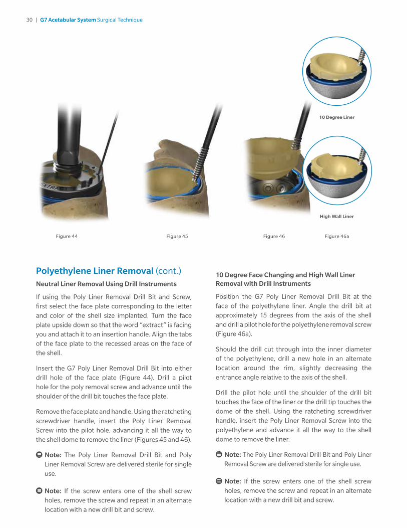
Polyethylene Liner Removal (cont.)Neutral Liner Removal Using Drill Instruments
If using the Poly Liner Removal Drill Bit and Screw, first select the face plate corresponding to the letter and color of the shell size implanted. Turn the face plate upside down so that the word “extract” is facing you and attach it to an insertion handle. Align the tabs of the face plate to the recessed areas on the face of the shell.
Insert the G7 Poly Liner Removal Drill Bit into either drill hole of the face plate (Figure 44). Drill a pilot hole for the poly removal screw and advance until the shoulder of the drill bit touches the face plate.
Remove the face plate and handle. Using the ratcheting screwdriver handle, insert the Poly Liner Removal Screw into the pilot hole, advancing it all the way to the shell dome to remove the liner (Figures 45 and 46).
Note: The Poly Liner Removal Drill Bit and Poly Liner Removal Screw are delivered sterile for single use.
Note: If the screw enters one of the shell screw holes, remove the screw and repeat in an alternate location with a new drill bit and screw.
10 Degree Face Changing and High Wall Liner Removal with Drill Instruments
Position the G7 Poly Liner Removal Drill Bit at the face of the polyethylene liner. Angle the drill bit at approximately 15 degrees from the axis of the shell and drill a pilot hole for the polyethylene removal screw (Figure 46a).
Should the drill cut through into the inner diameter of the polyethylene, drill a new hole in an alternate location around the rim, slightly decreasing the entrance angle relative to the axis of the shell.
Drill the pilot hole until the shoulder of the drill bit touches the face of the liner or the drill tip touches the dome of the shell. Using the ratcheting screwdriver handle, insert the Poly Liner Removal Screw into the polyethylene and advance it all the way to the shell dome to remove the liner.
Note: The Poly Liner Removal Drill Bit and Poly Liner Removal Screw are delivered sterile for single use.
Note: If the screw enters one of the shell screw holes, remove the screw and repeat in an alternate location with a new drill bit and screw.
Figure 45 Figure 46Figure 44 Figure 46a
10 Degree Liner
High Wall Liner
31 | G7 Acetabular System Surgical Technique
Figure 48 Figure 49Figure 47
15 Degrees
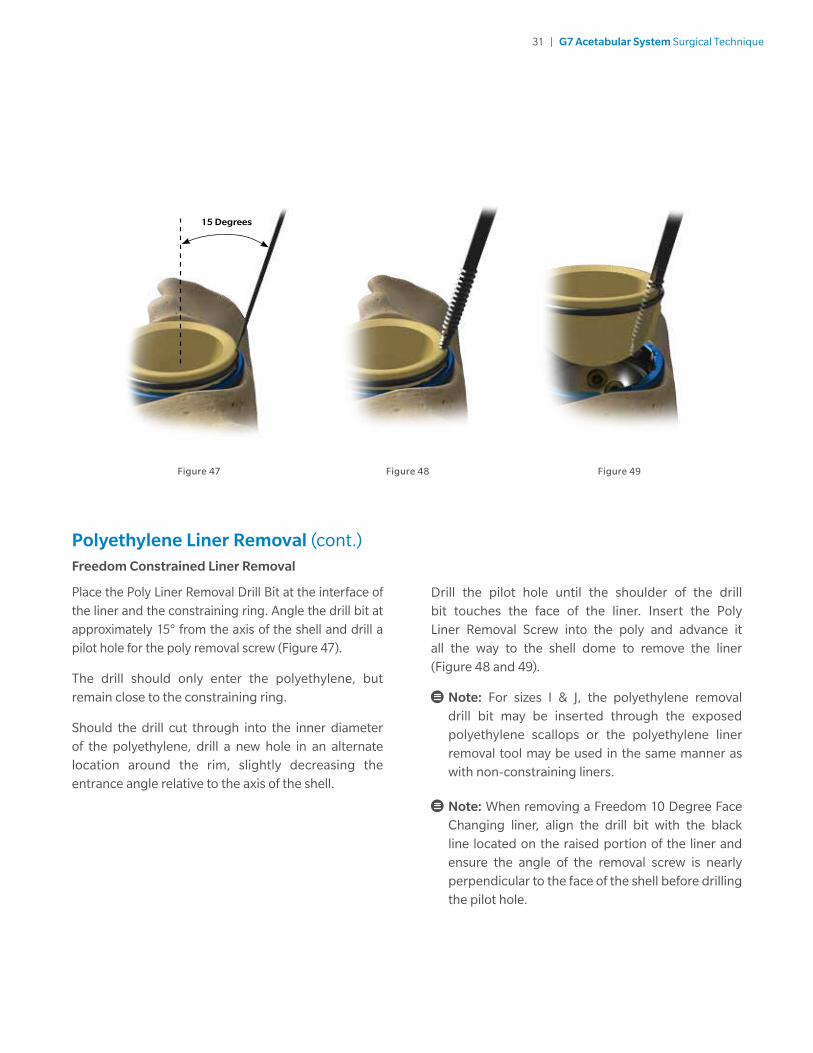
Polyethylene Liner Removal (cont.)Freedom Constrained Liner Removal
Place the Poly Liner Removal Drill Bit at the interface of the liner and the constraining ring. Angle the drill bit at approximately 15° from the axis of the shell and drill a pilot hole for the poly removal screw (Figure 47).
The drill should only enter the polyethylene, but remain close to the constraining ring.
Should the drill cut through into the inner diameter of the polyethylene, drill a new hole in an alternate location around the rim, slightly decreasing the entrance angle relative to the axis of the shell.
Drill the pilot hole until the shoulder of the drill bit touches the face of the liner. Insert the Poly Liner Removal Screw into the poly and advance it all the way to the shell dome to remove the liner (Figure 48 and 49).
Note: For sizes I & J, the polyethylene removal drill bit may be inserted through the exposed polyethylene scallops or the polyethylene liner removal tool may be used in the same manner as with non-constraining liners.
Note: When removing a Freedom 10 Degree Face Changing liner, align the drill bit with the black line located on the raised portion of the liner and ensure the angle of the removal screw is nearly perpendicular to the face of the shell before drilling the pilot hole.

32 | G7 Acetabular System Surgical Technique
Figure 50
Primary Shell RemovalTo remove the acetabular shell ensure all bone screws have been removed. Thread the extractor tool to a standard slap hammer and thread into the apical hole of the shell. Utilize the slap hammer to pull the shell directly out of the acetabulum, conserving as much bone as possible (Figure 50). Once the component is removed, careful evaluation of the acetabulum is suggested, with close attention to the integrity of the anterior/posterior columns and the medial wall. Any osteolytic cysts should be curetted and irrigated.
33 | G7 Acetabular System Surgical Technique
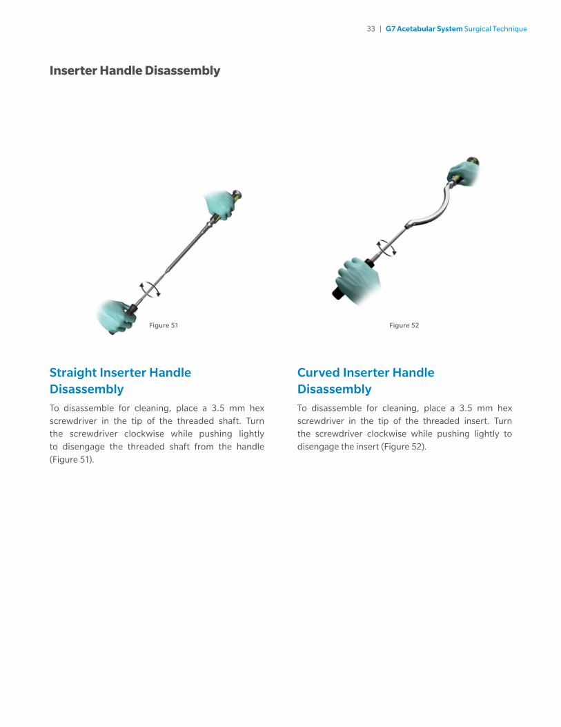
Figure 51
Straight Inserter Handle DisassemblyTo disassemble for cleaning, place a 3.5 mm hex screwdriver in the tip of the threaded shaft. Turn the screwdriver clockwise while pushing lightly to disengage the threaded shaft from the handle (Figure 51).
Curved Inserter Handle Disassembly To disassemble for cleaning, place a 3.5 mm hex screwdriver in the tip of the threaded insert. Turn the screwdriver clockwise while pushing lightly to disengage the insert (Figure 52).
Figure 52
Inserter Handle Disassembly
34 | G7 Acetabular System Surgical Technique
Indications
1. Noninflammatory degenerative joint disease including osteoarthritis and avascular necrosis.
2. Rheumatoid arthritis.
3. Correction of functional deformity
4. Treatment of non-union, femoral neck fracture, and trochanteric fractures of the proximal femur with head involvement, unmanageable by other techniques.
5. Revision procedures where other treatment or devices have failed.
Porous acetabular shells and femoral stems are indicated for uncemented biological fixation. Non-coated or polyethylene components may be used with mating components that are indicated for either cemented or uncemented use.
Indications for Biomet G7 Freedom Constrained Liners:
The Biomet G7 Freedom Constrained Liner is indicated for use as a component of a total hip prosthesis in primary and revision patients at high risk of dislocation due to a history of prior dislocation, bone loss, joint or soft tissue laxity, neuromuscular disease, or intraoperative instability, and for whom all other options to constrained Acetabular components have been considered.
Contraindications
Absolute contraindications include: infection, sepsis, and osteomyelitis.
Relative contraindications include: 1) uncooperative patient or patient with neurologic disorders who are incapable of following directions, 2) osteoporosis, 3) metabolic disorders which may impair bone formation, 4) osteomalacia, 5) distant foci of infections which may spread to the implant site, 6) rapid joint destruction, marked bone loss or bone resorption apparent on roentgenogram, and 7) vascular insufficiency, muscular atrophy, or neuromuscular disease.
Contraindications when shell is used with Biomet G7 Freedom Constrained Liner:
Bone or musculature compromised by disease, infection, or prior implantation that cannot provide adequate support or fixation for the prosthesis.
For full prescribing information, including Indications for Use, Contraindications, Warnings, Precautions and Possible Adverse Effects, see the package insert and “Patient Risk Information” tab on zimmerbiomet.com.


Notes


All content herein is protected by copyright, trademarks and other intellectual property rights owned by or licensed to Zimmer Biomet or its affiliates unless otherwise indicated, and must not be redistributed, duplicated or disclosed, in whole or in part, without the express written consent of Zimmer Biomet.
BIOLOX® is a trademark of CeramTec GmbH.
This material is intended for health care professionals and the Zimmer Biomet sales force. Distribution to any other recipient is prohibited.
For product information, including indications, contraindications, warnings, precautions, potential adverse effects and patient counseling information, see the package insert and www.zimmerbiomet.com
© 2016 Zimmer Biomet
0190.1-US-en-REV1016
CE mark on a surgical technique is not valid unless there is a CE mark on the product label.
References
1. Rothman, R. et al. Primary Total Hip Arthroplasty with an Uncemented Femoral Component. A Long-Term Study of the Taperloc Stem. Journal of Arthroplasty. 19(2): 151-6, 2004.
2. McLaughlin, J.R. and Lee, K.R. Total Hip Arthroplasty in Young Patients: 8 to 13 Year Results Using an Uncemented Stem. Clinical Orthopaedics and Related Research. 373:153-63, 2003.
3. Hozack, W. et al. Primary Cementless Hip Arthroplasty with a Titanium Plasma Sprayed Prosthesis. Clincal Orthopaedics and Related Research. 33(3): 217-25, 1996.
4. Keisu, K. et al. Primary Cementless Total Hip Arthroplasty in Octogenarians: Two to Eleven-Year Follow-Up. Journal of Bone and Joint Surgery. 83: 359, 2001.
5. Parvizi, J. et al. Prospective Matched-Pair Analysis of Hydroxyapatite- Coated and Uncoated Femoral Stems in Total Hip Arthroplasty. Journal of Bone and Joint Surgery. 83: 783-6, 2004.
6. Head, W. et al. A Titanium Cementless Calcar Replacement Prosthesis in Revision Surgery of the Femur: 13-Year Experience. Journal of Arthroplasty. 16(8): 183-7, 2001.
7. Meding, K., et al. Minimum Ten-Year Follow-up of a Straight-Stemmed, Plasma Sprayed, Titanium-Alloy, Uncemented Femoral Component in Primary Total Hip Arthroplasty. Journal of Bone and Joint Surgery. 86: 92-7, 2004.
Legal ManufacturerBiomet Orthopedics P.O. Box 58756 E. Bell DriveWarsaw, Indiana 46581-0587 USA
Biomet UK Ltd.Waterton Industrial EstateBridgend, South WalesCF31 3XA UK
Note: For Ceramic components contained within this Surgical Technique Biomet UK, Ltd is the Legal Manufacturer.
www.zimmerbiomet.com
0086