ga-based multi-objective optimization of active …...mathematical model of nonlinear quarter car is...
TRANSCRIPT
ORIGINAL PAPER Open Access
GA-based multi-objective optimization ofactive nonlinear quarter car suspensionsystem—PID and fuzzy logic controlMahesh P. Nagarkar1,2*, Yogesh J. Bhalerao3, Gahininath J. Vikhe Patil2 and Rahul N. Zaware Patil4
Abstract
Background: The primary function of a suspension system is to isolate the vehicle body from road irregularitiesthus providing the ride comfort and to support the vehicle and provide stability. The suspension system has toperform conflicting requirements; hence, a passive suspension system is replaced by the active suspension systemwhich can supply force to the system. Active suspension supplies energy to respond dynamically and achieverelative motion between body and wheel and thus improves the performance of suspension system.
Methods: This study presents modelling and control optimization of a nonlinear quarter car suspension system. Amathematical model of nonlinear quarter car is developed and simulated for control and optimization in Matlab/Simulink® environment. Class C road is selected as input road condition with the vehicle traveling at 80 kmph.Active control of the suspension system is achieved using FLC and PID control actions. Instead of guessing and ortrial and error method, genetic algorithm (GA)-based optimization algorithm is implemented to tune PIDparameters and FLC membership functions’ range and scaling factors. The optimization function is modeled as amulti-objective problem comprising of frequency weighted RMS seat acceleration, Vibration dose value (VDV), RMSsuspension space, and RMS tyre deflection. ISO 2631-1 standard is adopted to assess the ride and health criterion.
Results: The nonlinear quarter model along with the controller is modeled and simulated and optimized in aMatlab/Simulink environment. It is observed that GA-optimized FLC gives better control as compared to PID andpassive suspension system. Further simulations are validated on suspension system with seat and human model.Parameters under observation are frequency-weighted RMS head acceleration, VDV at the head, crest factor, andamplitude ratios at the head and upper torso (AR_h and AR_ut). Simulation results are presented in time andfrequency domain.
Conclusion: Simulation results show that GA-based FLC and PID controller gives better ride comfort and healthcriterion by reducing RMS head acceleration, VDV at the head, CF, and AR_h and AR_ut over passive suspension system.
Keywords: Multi-objective optimization, Genetic algorithm, Nonlinear quarter car, PID, FLC
* Correspondence: [email protected] College of Engineering, Ahmednagar, MS 414005, India2Research Department of Mechanical Engineering, AVCoE, Sangamner, MS,IndiaFull list of author information is available at the end of the article
© The Author(s). 2018 Open Access This article is distributed under the terms of the Creative Commons Attribution 4.0International License (http://creativecommons.org/licenses/by/4.0/), which permits unrestricted use, distribution, andreproduction in any medium, provided you give appropriate credit to the original author(s) and the source, provide a link tothe Creative Commons license, and indicate if changes were made.
Nagarkar et al. International Journal of Mechanical and Materials Engineering (2018) 13:10 https://doi.org/10.1186/s40712-018-0096-8
BackgroundThe main function of an automotive suspension systemis to support the vehicle weight, to isolate the occupantsagainst the excitations caused by road unevenness andthus providing the ride comfort and better handling, andto keep the contact between tyre and ground. The taskof the suspension system is a trade-off between ride andperformance as ride comfort needs soft suspension sys-tem whereas to follow track and support vehicle weightstiff suspension system is required.The primary objective of the active suspension system is
to replace the passive suspension system by a controlledsystem which can supply force to the system. Active sus-pension supplies energy to respond dynamically andachieve relative motion between the body and the wheel.Thus, to changing road conditions, active suspension sys-tem improves the performance of the suspension systemsuch as ride comfort, suspension or rattle spacedisplacement, tyre displacement, and body displacements(Wong 2001). For active control, various control strategiesare implemented like optimal control, robust control, non-linear control, nonlinear control with backstepping, slidingmode control, intelligent control, neural control, and hy-brid control. One of the main objectives was to minimizebody acceleration to improve ride comfort.Metered et al. (2015) had implemented particle swarm
optimization (PSO) algorithm to tune the PID controllerimplemented on a semi-active quarter car suspension sys-tem. A 2DoF model with MR damper is simulated in aMatlab/Simulink environment with bump and randomroad inputs. The system was tested in time and frequencydomain. It was observed that POS tuned PID controllerimproves ride comfort and vehicle stability. Kesarkar andSelvaganesan (2015) designed fractional order PID con-troller using artificial bee colony algorithm with objectivefunctions such as integral absolute error, integral squareerror, and integral time absolute error implemented to amulti-modal complex optimization problem. The authorsobserved that the results were promising as compared tothe conventional PID method. Niu (2014) had imple-mented GA-based optimization method to tune PID pa-rameters of the active suspension system. Absolute errorcontrol is used as an objective function to tune the PIDparameters. It was observed that the GA-based optimizedPID controller improves the dynamic performance of theactive suspension system and improves stability. Gad et al.(2017) implemented a fractional order PID controller to asemi-active seat suspension. PID parameters are tunedusing multi-objective GA for a seat suspension systemusing the 6-DoF human body. It is observed thatGA-based PID controller improved SEAT value, VDV ra-tio, and crest factor as compared to the passive systemand classical PID controller. Results are obtained in timeas well as frequency domain. Tammam et al. (2013)
implemented a multi-objective GA-based PID controllerto control the load frequency of a single area power sys-tem. It is observed that GA-based PID controller is simpleand easy to implement and improves system performanceeffectively. Abdelrassoul et al. (2016) studied the perform-ance of the PV system based on GA-optimized PID con-troller. Here, PID controller is implemented to enhancePV system output with minimum overshoot and mini-mum rise time in output voltage with the better response.Chen and Chang (2006) studied GA-based PID tuning foractive magnetic bearing. The proposed PID controllershows that the active magnetic bearing had good staticand dynamic performance and showed better performanceand effectiveness.It is observed that optimization of PID controller
applied to suspension system is carried out in singleobjective nature (Metered et al. 2015; Niu 2014) whereas(Kesarkar and Selvaganesan 2015) presented amulti-modal optimization approach and (Gad et al.2017) presented dual objective function optimization.Kalaivani et al. (2014) studied a fuzzy logic-based ac-
tive quarter car suspension system. A hybrid differentialevolution bio-geography based optimization algorithm isused to tune the FLC controller. RMS body accelerationis used as performance index to study the PID and newlyproposed FLC controller. It was observed that the pro-posed controller improves the ride comfort. Taskin et al.(2017) implemented the FLC controller on a quarter cartest rig. Time and frequency domain response of sprungmass displacement, acceleration, and suspension spacedeflection and actuator force are studied and comparedwith passive suspension system and observed that FLCcontroller performance better. Huang and Chao (2000)implemented a fuzzy logic controller-based active sus-pension system on a quarter car model. Results showedthat the control strategy improves ride comfort reducingthe oscillations of the body. Salem and Aly (2009) hadstudied the 2-DoF quarter suspension system. FLC isused to control the quarter car active suspension system.Body acceleration is used as a criterion to study the ridecomfort of a suspension system, along with handling.FLC and PID controller are studied and observed thatFLC performs better compared to the PID controller.Rajendiran and Lakshmi (2016) analyzed active controlof 2-DoF suspension system using PID control and FLCalong with seat and driver model. It was observed thatFLC improves ride comfort than that of PID control andpassive system. Taskin et al. (2007) studied the FLC con-troller to enhance ride comfort. From time response ofthe active system, it is observed that body displacementis minimized without losing suspension working space.Results were obtained in the frequency domain whichshows improved ride comfort. From above discussions, itis observed that researchers (Taskin et al. 2017; Huang
Nagarkar et al. International Journal of Mechanical and Materials Engineering (2018) 13:10 Page 2 of 20

and Chao 2000; Salem and Aly 2009; Rajendiran and Lak-shmi 2016) have successfully implemented the FLC forride control applications, whereas (Kalaivani et al. 2014)optimized FLC using a single optimization function.Talib and Darus (2014) implemented a semi-active
suspension system using FLC and PID controllers. Per-formance of both the controllers is optimized by thePSO algorithm for mean square error. Optimized FLC,PID controllers are compared with a passive suspensionsystem for body displacement, acceleration, tyre dis-placement for bump, and hole disturbances. It is ob-served that the FLC controller gave better results ascompared to the PID controller. Celin and Rajeswari(2012) implemented type-2 FLC to the active suspensionsystem. Sprung mass displacement, RMS acceleration,suspension space, and tyre deflection criterions wereused to study the FLC and passive suspension system.GA-coded FLC outperforms the FLC and passive sus-pension system. D’Amato and Viassolo (2000) presentedthe active suspension system to reduce the body acceler-ation to improve comfort. FLC is used to control whereparameters are tuned by GA optimization. This method-ology improves ride comfort thus was effective in case of aquarter car suspension system. Li and Du (2006) pre-sented a GA-based approach to optimize rule base andscaling factors. The parameters were coded intoreal-coded strings and treated as chromosomes duringoptimization. The GA-based optimization approach im-proves the performance of FLC. Liu et al. (2016) had suc-cessfully optimized the membership functions of FLC to amaximum power point tracking (MPPT) algorithm usingPSO algorithm to improve averaged tracking error and fit-ness value. Bouarroudj et al. (2017) had presented thecomparative analysis of Mamdani FLC with Gaussianmembership functions for MPPT of PV system using GAand PSO approach. It was observed that PSO and GA op-timized FLC gives better results in terms of performance.This paper presents the mathematical modelling of a
nonlinear quarter car (NLQC) along with a human model.The nonlinear quarter car model consists of quadratic tyrestiffness and cubic stiffness in suspension spring as non-linearities. PID and FLC are implemented with the controlobjective to minimize frequency weighted RMS sprungmass acceleration (hereafter called as RMS sprung massacceleration), VDV, RMS suspension space requirement,and RMS tyre deflection along with RMS optimal controlforce. The constraints on optimization are maximum con-trol force, maximum sprung mass acceleration, maximumsuspension space requirement, and maximum tyre deflec-tion. Due to multi-objective natures of optimal controland conflicting control objectives, the key issue is to selectthe PID gain values and range of fuzzy input and outputmembership functions and scaling factors to fulfill theconflicting requirements. Trial and error method and or
manual tuning of the PID controller and FLC are cumber-some and time-consuming. Hence, a GA-based evolution-ary optimization technique is used to search the optimumparameters. During optimization, a nonlinear optimalcontrol system is simulated in a Matlab/Simulink® envir-onment where the tuning parameters are selected fromthe search space. The output of the nonlinear optimalcontrol system is fed to the optimization algorithm to de-termine the objectives and validate the constraints. Theoptimization procedure is repeated up to 100 generations.Further, the optimization results are validated on a quartercar with seat and human model. Results are presented inboth time domain and frequency domain.
MethodsMathematical modelling—nonlinear quarter carsuspension-seat-human modelA suspension system consists of damper and coilsprings. Researchers have used various mathematicalmodels viz. quarter car model having 2-DoF, a half carmodel having 4-DoF, and full car model. In this study, a2-DoF quarter-car model is implemented for ride andcontrol applications (Metered et al. 2015; Kalaivani et al.2014; Taskin et al. 2017; Huang and Chao (2000); Salemand Aly 2009; Rajendiran and Lakshmi 2016).Mathematical modeling is carried out using linear
springs and damper by various authors (Kalaivani et al.2014; Taskin et al. 2017; Huang and Chao (2000); Salemand Aly 2009; Rajendiran and Lakshmi 2016). But it isobserved that spring exhibits nonlinear nature so do thetyre (Fuller et al. 1996). Thus, the nonlinearity should beconsidered during modeling. McGee et al. (2005) studiednonlinearities in the suspension system using a fre-quency domain technique and are validated experimen-tally with shaker data. It was observed quadratic andcubic stiffness and Coulomb friction nonlinearities inthe suspension system (McGee et al. 2005). A chaotic re-sponse was presented by Zhu and Ishitobi (2006). Theyused a 7-DoF model with tyre stiffness and suspensionspring stiffness nonlinearities. Bifurcation and chaoticresponse of 2-DoF model with tyre stiffness and suspen-sion spring stiffness nonlinearities were presented byLixia and Wanxiang (2008).In the present analysis, a nonlinear quarter car model
having quadratic tyre stiffness and cubic stiffness in sus-pension spring nonlinearities are considered.A human model suggested by (Boileau and Rakheja
1998) is incorporated further in this study. The model ishaving 4-DoFs consisting of head and neck mass (mh),chest and upper torso mass (mut), lower torso mass(mlt), and thigh and pelvis mass (mt). The human modelconsiders typical driving conditions such as seated pos-ture with feet support and hands held in driving condi-tions (refer to Fig. 1).
Nagarkar et al. International Journal of Mechanical and Materials Engineering (2018) 13:10 Page 3 of 20

According to D’Alembert’s principle, the governingequations of motion representing nonlinear quarter carsuspension-seat-human model are represented as –
mus€xus ¼ −kt xus−xrð Þ þ ks xs−xusð Þ þ cs _xs− _xusð Þ þ ktnl xus−xrð Þ2
þksnl xs−xusð Þ3− f
ms€xs ¼ −ks xs−xusð Þ−cs _xs− _xusð Þ−ksnl xs−xusð Þ3 þ k f x f −xs� �
þc f _x f − _xs� �þ f
mf €x f ¼ −k f x f −xs� �
−c f _x f − _xs� �þ kc xc−x f
� �þ cc _xc− _x f� �
mc€xc ¼ −kc xc−x f� �
−cc _xc− _x f� �þ ktp xt−xcð Þ þ ctp _xt− _xcð Þ
mt€xt ¼ −ktp xt−xcð Þ−ctp _xt− _xcð Þ þ klt xlt−xtð Þ þ clt _xlt− _xtð Þ
mlt€xlt ¼ −klt xlt−xtð Þ−clt _xlt− _xtð Þ þ kut xut−xltð Þ þ cut _xut− _xltð Þ
mut€xut ¼ −kut xut−xltð Þ−cut _xut− _xltð Þ þ kh xh−xutð Þ þ ch _xh− _xutð Þ
mh€xh ¼ −kh xh−xutð Þ−ch _xh− _xutð Þ
g
ð1Þ
The nonlinear quarter car seat-suspension-humanmodel parameters are as follows:
mh = 5.31; ch = 400; kh = 310,000;mut = 28.49; cut = 4750; kh = 183,000;
mlt = 8.62; clt = 4585; klt = 162,800;mt = 12.78; ct = 2064; kt = 90,000;mc = 1; cc = 200; kc = 18,000;mf = 15; cf = 830; kf = 31,000;ms = 290; cs = 700; ks = 23,500; ksnl = 100ks (Lixia andWanxiang 2008);mus = 40; kt = 190,000; ktnl = 1.5 kt (Zhu and Ishitobi2006).
The nonlinear quarter car having quadratic stiffnessnonlinearity in the tyre and cubic stiffness in suspensionspring is modeled and simulated in Matlab/Simulink®.Further, the simulations are carried out on a quarter carmodel with seat consisting frame and cushion with a hu-man model.
Control theory—PID controlPID stands for proportional, integral, and derivative andis a classical controller used for several control applica-tions (Metered et al. 2015; Kesarkar and Selvaganesan2015; Niu 2014; Gad et al. 2017; Tammam et al. 2013;Abdelrassoul et al. 2016; Chen and Chang 2006). ThePID controllers are so designed that continuous atten-tion of the operator is eliminated. As the PID controllerhas designed a derivative nature type, small variation ofoutput can be easily avoided. A PID controller isdepicted in Fig. 2. The set point is where the
Fig. 1 Nonlinear quarter car suspension system—with seat and human model (Nagarkar et al. 2016)
Nagarkar et al. International Journal of Mechanical and Materials Engineering (2018) 13:10 Page 4 of 20

measurement should be. An error is defined as the dif-ference between the set point r(t) and measurement y(t).PID computes the control signal based on the followingequations:
u tð Þ ¼ Kp e tð Þ þ Ki
Ze tð Þdt þ Kd
ddt
e tð Þ ð2Þ
e tð Þ ¼ r tð Þ−y tð Þ ð3Þ
The error, e(t), variable being adjusted is called themanipulated variable which usually is equal to the out-put of the controller. As there is a change in measure-ment or set point, so is the output of the controller.Generally, Z-N tuning or auto-tuning is used to tune theP, I and D parameters of the controller.
Control theory—fuzzy logic controlFLC uses heuristic information for control applications.The FLC uses rule-base derived through an operator’sexperience and thus acts as a human-in-the-loop con-troller providing human experience to achieve high per-formance (Kalaivani et al. 2014; Taskin et al. 2017;Huang and Chao 2000).Figure 3 represents the structure of a typical FLC im-
plemented for a 2-DOF suspension system. Here, two in-puts (error e and ec) and one output (force fFLC) FLCwith rule-base is implemented. Sprung mass velocity(error e) and acceleration (change in error ec) are usedas input, and control force (fFLC) is output. FLC rulebase is a linguistic-based rule base which incorporatespast human experience. Table 1 represents the rule basefor two input-one output rule base for ride comfort. Fig-ure 4 represents the surface plot rule base as stated inTable 1.
Fig. 2 PID control
Fig. 3 Fuzzy logic controller
Nagarkar et al. International Journal of Mechanical and Materials Engineering (2018) 13:10 Page 5 of 20

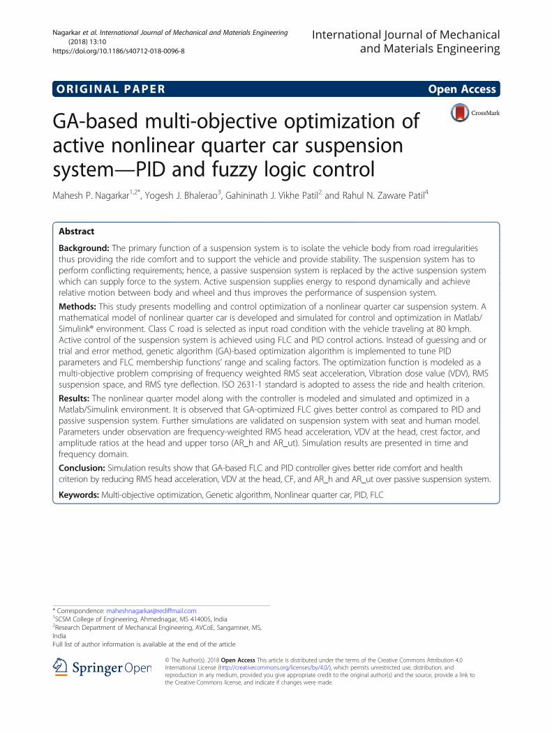
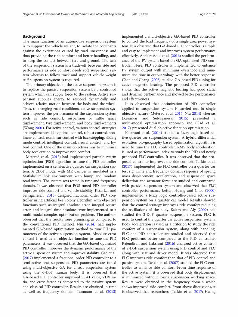
Firstly, FLC decomposes the input into fuzzy sets,called as fuzzification, using membership functions(MF). Primarily membership functions map practicalspace to fuzzy space, known as fuzzification. Here, trap-ezoidal membership functions are used for input andoutput variables (refer Figs. 5, 6, and 7). The FLC con-sists of seven membership functions each, ie., for two in-puts (error e and change in error ec) and an output fFLC;these are NL, NM, NS, ZE, PS, PM, PL. Mamdani typefuzzy inference system (FIS) is used. Defuzzification isthe process which maps the variables back to practicalspace from fuzzy space. Centroid defuzzification methodis used in this FLC.
Objective functionsOne of the key factors in optimization problems is tochoose proper objective functions. Here, the controlstrategies are implemented to improve ride characterized
by RMS sprung mass acceleration, VDV, RMS suspen-sion space deflection, RMS tyre deflection, and RMScontroller force.
RMS accelerationAs per ISO 2631-1 (1997), RMS acceleration is given by
Aws ¼ f1T
Z T
0½awðtÞ�2dtg
12
ð4Þ
A major portion of the vibration experienced by theoccupants of an automobile enters the body through theseat (Van Niekerk et al. 2003; Bovenzi 2005). The healthrisk increases as the exposure time to vibrations in-creases. Hence, is it necessary to measure the wholebody vibrations for ride and health criterion. As per ISO2631-1 (1997), VDV is one measure for whole body vi-brations. VDV also called as fourth power vibrationdose. VDV is the method of assessing the cumulative ef-fect (dose) of the vibration.
Vibration dose value (VDV)VDV is the fourth power of acceleration time histories.It is expressed as -
VDVs ¼Z T
0aw tð Þ½ �4dt
� �14
ð5Þ
Suspension travelSuspension travel is characterized by the relative travelbetween the sprung mass and unsprung mass. Due to
Table 1 Fuzzy logic rule table (2-DoF active suspension system)
f ec
e NL NM NS ZE PS PM PL
NL PL PL PM PS PS PS ZE
NM PL PM PS PS PS ZE NS
NS PM PS ZE ZE ZE NS NM
ZE PM PS ZE ZE ZE NS NM
PS PM PS ZE ZE ZE NS NM
PM PS ZE ZE ZE ZE NM NL
PL ZE NS NS NS NM NL NL
N negative, ZE zero, P positive, L large, M medium, S small
Fig. 4 Fuzzy logic rule—surface plot
Nagarkar et al. International Journal of Mechanical and Materials Engineering (2018) 13:10 Page 6 of 20
random input, RMS suspension space travel is taken asone of the objective functions.
Suspension Travel ¼ xs−xus ð6Þ
RMS Suspension Travel ¼ 1T
Z T
0xs tð Þ−xus tð Þð Þ½ �2dt
� �12
ð7Þ
Dynamic tyre deflectionDynamic tyre force is related to tyre deflection. Due tothe random nature of input, the RMS of tyre deflectionis the next objective function.
Tyre Deflection ¼ xus−xr ð8Þ
RMS Tyre Deflection ¼ 1T
Z T
0xus tð Þ−xr tð Þð Þ½ �2dt
� �12
ð9ÞControl force is introduced as one of the objective
functions, to find optimum control force to achieve ridecomfort.
RMS f ¼ 1T
Z T
0f tð Þð Þ½ �2dt
� �12
ð10Þ
According to Baumal et al. (1998), at least, 125 mm ofsuspension travel is required, and maximum seat acceler-ation should not increase 4.5 m/s
2to avoid hitting the sus-
pension stop. To minimize dynamic tyre forces, maximumtyre deflection should not increase 0.0508 m. These parame-ters are included as constraints in the optimization problem.
Fig. 5 Membership function (e)
Fig. 6 Membership function (ec)
Nagarkar et al. International Journal of Mechanical and Materials Engineering (2018) 13:10 Page 7 of 20

The formulation of the optimization problem is as follows:
f ob j1 ¼ Minimize ðRMS f Þ
f obj2 ¼ Minimize VDVsð Þ
f obj3 ¼ Minimize Awsð Þ
f obj4 ¼ Minimize RMS Suspension Travelð Þ
f obj5 ¼ Minimize RMS Tyre Deflectionð Þ
Subject to constraints:
amax seat ≤ 4:5ms2; Max:ðxs−xusÞ ≤0:125m;
Max:ðxus−xrÞ ≤0:0508m; fmax≤2000 N:
Multi-objective optimizationResearchers have invented several meta-heuristicoptimization algorithms to optimize the problems inseveral fields. These algorithms have implemented onseveral mathematical problems involving single objectiveoptimization to multi-objective optimization and pro-vided excellent results.The suspension system has to perform several conflict-
ing objectives such as ride comfort, road holding, and
suspension/rattle space requirements. Thus, theoptimization problem becomes a multi-objective type(consisting of RMS control force, VDV, RMS sprungmass acceleration, RMS suspension space requirement,and RMS dynamic tyre deflection as objective functions)with conflicts. As compared to a single objectiveoptimization problem, a multi-objective optimization(MOO) problem has to satisfy several objectives simul-taneously. Hence, multi-objective optimization using agenetic algorithm (GA) (Holland 1992; Holland 1975) isimplemented to solve the optimization problem.In the solution of MOO problems, MOO forms a
Pareto optimal front consisting of multiple optimal solu-tions. GA is implemented to optimize in multiple do-mains as it handles complex optimization problems withdiscontinuities, non-differentials, noisy functions, andfunctions with multi-modality. GA also supports parallelcomputations with obtaining Pareto front in a singlerun. Non-dominated sort GA-II (NSGA-II) (Deb et al.2002) is one of the MOEAs using GA strategy. NSGA-IIimplements non-dominated sort algorithm thus redu-cing the computational complexities. While sorting theparents and children, elitism is introduced in NSGA-II.In NSGA-II, to preserve the diversity and uniformspread of optimal front, a crowding distance (CD) (Debet al. 2002) operator is used. Chromosomes with betterfitness are assigned highest ranks, and thus, they deter-mine the domination.From the non-dominated front, parents are selected by
tournament selection and compared to the CD. New
Fig. 7 Membership function (U)
Table 2 Membership functionsMF Input 1 (e) Input 2 (ec) Output (f)
NL [− 1– 1 − 0.7 − 0.4] [− 1 − 1 − 0.6 − 0.3] [− 1 − 1 − 0.9 − 0.6]
NM [− 0.7− 0.5 − 0.3 − 0.05] [− 0.6 − 0.4 − 0.3 − 0.1] [− 0.9 − 0.7 − 0.5 − 0.2]
NS [− 0.4 − 0.2 − 0.1 0] [− 0.3 − 0.2 − 0.1 0] [− 0.6 − 0.3 − 0.2 0]
ZE [− 0.05 − 0.01 0.01 0.05] [− 0.1 − 0.025 0.025 0.1] [− 0.2 − 0.05 0.05 0.2]
PS [0 0.1 0.2 0.4] [0 0.1 0.2 0.3] [0 0.2 0.3 0.6]
PM [0.05 0.3 0.5 0.7] [0.1 0.3 0.4 0.6] [0.2 0.5 0.7 0.9]
PL [0.4 0.7 1 1] [0.3 0.6 1 1] [0.6 0.9 1 1]
Table 3 Design variables range—PID ControlDesignvariable
Range Size
Kp 15,000–2000 = 13,000 213 = 8192 < 13,000 < 214 = 16,384 14 bits
Ki 150–10 = 140 27 = 128 < 140 < 28 = 256 08 bits
Kd 50,000–15,000 = 35,000 215 = 32,768 < 35,000 < 216 = 65,536 16 bits
Nagarkar et al. International Journal of Mechanical and Materials Engineering (2018) 13:10 Page 8 of 20
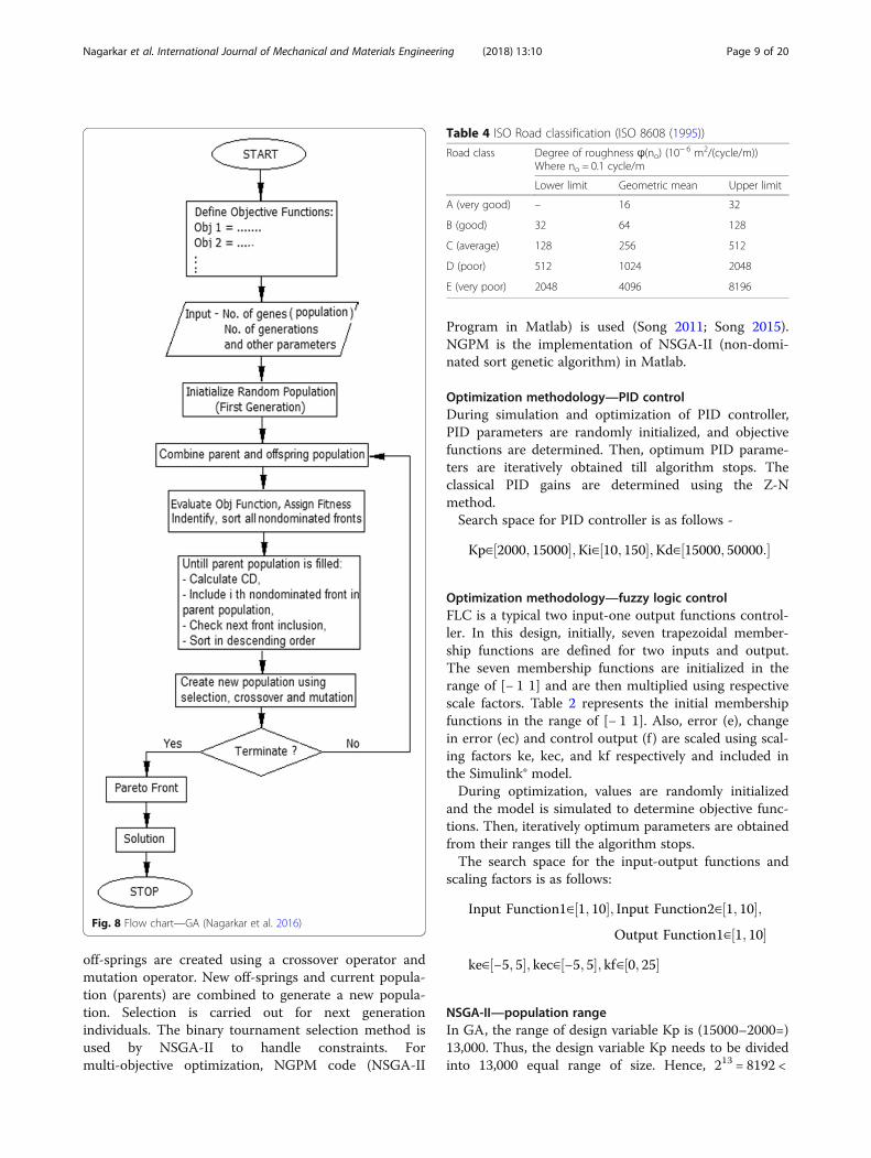
off-springs are created using a crossover operator andmutation operator. New off-springs and current popula-tion (parents) are combined to generate a new popula-tion. Selection is carried out for next generationindividuals. The binary tournament selection method isused by NSGA-II to handle constraints. Formulti-objective optimization, NGPM code (NSGA-II
Program in Matlab) is used (Song 2011; Song 2015).NGPM is the implementation of NSGA-II (non-domi-nated sort genetic algorithm) in Matlab.
Optimization methodology—PID controlDuring simulation and optimization of PID controller,PID parameters are randomly initialized, and objectivefunctions are determined. Then, optimum PID parame-ters are iteratively obtained till algorithm stops. Theclassical PID gains are determined using the Z-Nmethod.Search space for PID controller is as follows -
Kp∈ 2000; 15000½ �;Ki∈ 10; 150½ �;Kd∈ 15000; 50000:½ �
Optimization methodology—fuzzy logic controlFLC is a typical two input-one output functions control-ler. In this design, initially, seven trapezoidal member-ship functions are defined for two inputs and output.The seven membership functions are initialized in therange of [− 1 1] and are then multiplied using respectivescale factors. Table 2 represents the initial membershipfunctions in the range of [− 1 1]. Also, error (e), changein error (ec) and control output (f ) are scaled using scal-ing factors ke, kec, and kf respectively and included inthe Simulink® model.During optimization, values are randomly initialized
and the model is simulated to determine objective func-tions. Then, iteratively optimum parameters are obtainedfrom their ranges till the algorithm stops.The search space for the input-output functions and
scaling factors is as follows:
Input Function1∈ 1; 10½ �; Input Function2∈ 1; 10½ �;Output Function1∈ 1; 10½ �
ke∈ −5; 5½ �; kec∈ −5; 5½ �; kf∈ 0; 25½ �
NSGA-II—population rangeIn GA, the range of design variable Kp is (15000–2000=)13,000. Thus, the design variable Kp needs to be dividedinto 13,000 equal range of size. Hence, 213 = 8192 <
Fig. 8 Flow chart—GA (Nagarkar et al. 2016)
Table 4 ISO Road classification (ISO 8608 (1995))
Road class Degree of roughness ϕ(no) (10− 6 m2/(cycle/m))
Where no = 0.1 cycle/m
Lower limit Geometric mean Upper limit
A (very good) – 16 32
B (good) 32 64 128
C (average) 128 256 512
D (poor) 512 1024 2048
E (very poor) 2048 4096 8196
Nagarkar et al. International Journal of Mechanical and Materials Engineering (2018) 13:10 Page 9 of 20

13,000 < 214 = 16,384, i.e., 14 bits are required to storethe value of design variable Kp in the chromosome.Similarly, for other design variables, the bit required istabulated in Table 3.Hence, the total length of chromosome or gene is 14
+ 08 + 16 = 38 bits that are required, where the first14 bits are required for Kp, the next 08 bits are requiredfor Ki, and the next 16 bits are required for Kd. Popula-tion size is selected such that
Ns < population size < 2Ns, where Ns = string length(Alander 1992)Also, the range of variables for the FLC design variables
is small as compare to the PID controller. Thus, selectingpopulation size of 100 (Rosenthal and Borschbach 2014;Hernández-Díaz et al. 2008; Nagarkar et al. 2016) andoptimization is stopped after 100 generations. Figure 8 ex-plains the flowchart of the GA algorithm implemented formulti-objective optimization.
Fig. 9 Road surface (class C, velocity 80 kmph)
Fig. 10 Trade-off front—PID Control
Nagarkar et al. International Journal of Mechanical and Materials Engineering (2018) 13:10 Page 10 of 20

Results and discussionMulti-objective optimization of the non-linearquarter-car model is simulated in a Matlab/Simulink®environment using NSGA-II algorithm.The stationary road roughness is effectively described
by power spectral density (PSD). When a car moves at aconstant velocity v, the road roughness can be viewed asa stationary process in the space domain. The differen-tial equation of road roughness can be expressed as (Heet al. 2008; Zhang et al. 2007):
_xr tð Þ þ 2πnovxr tð Þ ¼ffiffiffiffiffiffiffiffiffiffiffiffiffiffiffiSq noð Þv
qw tð Þ ð11Þ
Equation (11) is modeled in the Simulink environmentto model the road surface. According to ISO 8608, roadsare divided into classes like A, B, C, D, and E. Class Aand B represents expressways or motorways, whereasclass C road is a typical average road type. Class B and Croads are generally country or district roads. Class Croad considers velocities of typical secondary roads ran-ging from ~ 30 kmph to ~ 60 kmph. The input roadcondition is modeled as class C road (average road) witha degree of road roughness 512 × 10−6 m2/(cycle/m)(Zhang et al. 2007; ISO 8608 1995). Refer to Table 4 forthe road roughness classification. The vehicle is travelingwith a velocity of 80 kmph. Figure 9 represents the classC road surface.
PID controllerThe trade-off front of 100 different solutions for object-ive functions satisfying the constraints is obtained afteroptimization. The trade-off front is shown in Fig. 10. Forride comfort and health criterion, RMS acceleration andVDV are selected as optimum values. Hence, for PIDcontroller P, D and D parameters’ gain values are se-lected for minimum valued of RMS acceleration andVDV and simulated further. Refer to Table 7 for the cor-responding optimized PID parameters.It is observed that the RMS acceleration for the
GA-optimized PID controller is 0.6178 m/s2, which is alittle uncomfortable. In GA-PID controlled system, RMS
acceleration is reduced by 34% (passive suspension sys-tem has RMS acceleration 0.9322 m/s2 which is uncom-fortable) and is reduced by 10% as compared to theclassical PID control. For GA optimized PID controller,VDV is reduced by 33% as compared to the passive sus-pension system and is reduced by 11% as compared toclassical PID control. Also, constraints are not violatedin the GA optimized system. The results of RMS optimalcontrol force, RMS sprung mass acceleration, RMS sus-pension space, RMS tyre deflection, maximum controllerforce, and maximum sprung mass acceleration are tabu-lated in Table 5 (refer to Fig. 11 for time domainresults).Further frequency domain analysis is carried out for
the PID controlled system and passive system. In fre-quency analysis, it is observed that the optimized PIDcontrolled system experiences low amplitudes of bodyaccelerations as compared to the passive suspension sys-tem (refer to Fig. 12). PID can reduce the amplitude ofbody accelerations at points 100 and 101 Hz frequencies.Also, it shows better performance over higher amplituderegions > 10 Hz.
Fuzzy logic controlDuring simulation 2-DOF nonlinear active suspensionsystem, it is excited by a random road disturbance. TheNSGA-II-based optimization is carried out and resultsare obtained using a MATLAB/SIMULINK. The velocityand acceleration of sprung mass are selected as an error(e) and change in error (ec) feedback signals for the2-DOF suspension system control.The trade-off front of 100 different solutions for ob-
jective functions satisfying the constraints is obtainedafter optimization. The trade-off front is shown inFig. 13. For ride comfort and health criterion, the mini-mum RMS acceleration and VDV are selected asoptimum values. Hence, FLC parameters, ke, kc, kf, andscaling factors for input-output membership functionsare selected having minimum values of RMS acceler-ation and VDV corresponding to the trade-off front and
Table 5 Optimization results—objective function and constraintsParameter Fuzzy logic control-GA PID-GA PID classical Passive system
RMS control force (N) 140.9662 445.4385 346.8979 –
VDV (m/s1.75) 1.1782 1.4410 1.6174 2.1509
Aw (m/s2) 0.5057 0.6178 0.6890 0.9322
RMS suspension space deflection (m) 0.0085 0.01007 0.008700 0.009311
RMS tyre deflection (m) 0.0042 0.008864 0.007300 0.004473
Max control force (N) 345.6605 1423.1810 1173.24400 –
Max acceleration (m/s2) 2.31900 1.8615 2.1800 3.16720
Max suspension space deflection (m) 0.02520 0.03426 0.03050 0.02640
Max tyre deflection (m) 0.01350 0.02639 0.02510 0.01840
Nagarkar et al. International Journal of Mechanical and Materials Engineering (2018) 13:10 Page 11 of 20

Fig. 12 PID control results—frequency domain
Fig. 11 PID control results—time domain
Nagarkar et al. International Journal of Mechanical and Materials Engineering (2018) 13:10 Page 12 of 20
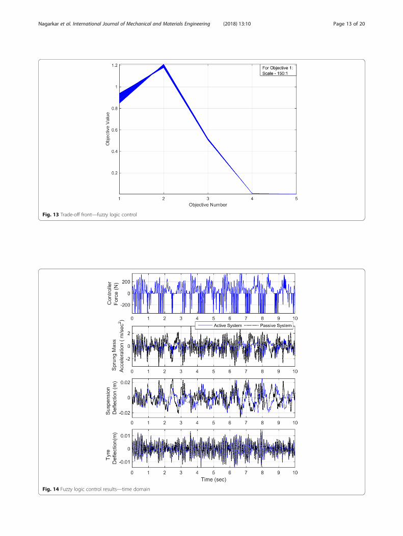
Fig. 14 Fuzzy logic control results—time domain
Fig. 13 Trade-off front—fuzzy logic control
Nagarkar et al. International Journal of Mechanical and Materials Engineering (2018) 13:10 Page 13 of 20

are simulated further. Refer to Table 7 for the corre-sponding optimized FLC parameters.It is observed that RMS acceleration for the
GA-optimized FLC is 0.5057 m/s2, which is a little un-comfortable. In the fuzzy logic control system, RMS ac-celeration is reduced by 46% as compared to the passivesystem (passive suspension system has RMS acceleration0.9322 m/s2 which is uncomfortable) and by 18% ascompared to GA-based PID controller. Also, VDV forGA-based FLC is reduced by 45% as compared to thepassive suspension system and by 18% as compared tothe GA-based PID controller. Also, the RMS suspensionspace and RMS tyre deflection are less for FLC as
compared to the GA-based PID controller and passivesuspension system. The constraints are not violated in GAoptimized FLC. The results of RMS optimal control force,RMS sprung mass acceleration, RMS suspension space,RMS dynamic tyre deflection, and maximum controllerforce are maximum sprung mass acceleration are tabu-lated in Table 5 (refer to Fig. 14 for the time domainresults). Results are also shown in the bar chart (refer toFig. 15).From simulations and Table 5, it is observed that the
GA-tuned FLC controller performs better as comparedto the GA-tuned PID controller. In the case ofGA-tuned FLC controller, VDV and RMS acceleration is
Fig. 16 Fuzzy logic control results—frequency domain
Fig. 15 Optimization results—objective functions and constraints
Nagarkar et al. International Journal of Mechanical and Materials Engineering (2018) 13:10 Page 14 of 20

reduced by 18.23% and 18.14% as compared to theGA-tuned PID controller. Also, RMS suspension spacedeflection and RMS tyre deflection is less for theGA-tuned FLC controller.Further, the frequency domain analysis is also carried
out for the FLC system and passive system. For fre-quency analysis, it is observed that the FLC system expe-riences low amplitudes of vibrations over a broaderrange of frequencies as compared to the passive suspen-sion system (refer to Fig. 16). The FLC can reduce theamplitude of body accelerations at points 100 and101 Hz frequencies and also shows better performanceover higher amplitude regions > 10 Hz.Further, to study the controller performance, the non-
linear quarter car suspension system is simulated overclass C and class D roads with vehicle speed rangingfrom 20 to 160 kmph. Figure 17 shows performanceover class C road type. For class C road, the maximumvalue of VDV is 1.8385 m/s1.75 and is observed at160 kmph, for GA-tuned PID controller. Whereas for
the GA-based FLC maximum VDV is 1.7205 m/s1.75.The maximum value of RMS sprung mass accelerationis 0.7910 m/s2 for the GA-tuned PID controller and0.7065 m/s2 for the GA-FLC controller and is observedat 160 kmph. From Fig. 17, it is observed that, for FLCcontroller, up to 130 kmph speed, the RMS sprung massacceleration is in a slightly uncomfortable region as perISO2631-1:1997. Whereas for the PID controller, thesame level is achieved up to 100 kmph. Above thesespeed limits, the RMS sprung mass acceleration fallsunder the fairly uncomfortable region. Other parameterslike RMS suspension space and RMS tyre deflection arealso represented in Fig. 17.The non-linear quarter car is also simulated over class
D road. Figure 18 shows the performance of the nonlin-ear quarter car with both controllers over class D road.From the figure, it is observed that FLC and PID con-troller shows nearly the same performance for the RMSsprung mass acceleration. The VDV value is maximumat 160 kmph for both controllers. The maximum VDV
Fig. 17 Performance of FLC and PID controller—class C road
Nagarkar et al. International Journal of Mechanical and Materials Engineering (2018) 13:10 Page 15 of 20

for PID controller is 2.1874 m/s1.75 and for FLC controllerVDV is on the slightly higher side and is 2.6091 m/s1.7.The maximum RMS sprung mass is the acceleration isobserved at 160 kmph for both controllers and is0.9391 m/s2 for the GA-tuned PID controller and0.9586 m/s2 for GA-FLC controller respectively. FromFig. 18, it is observed that for FLC controller, up to80 kmph speed, the RMS sprung mass acceleration is in aslightly uncomfortable region whereas for PID controller,the same level is achieved up to 70 kmph as perISO2631-1:1997. Above these speed limits, RMS sprung
mass acceleration falls under the fairly uncomfortableregion.To check the effect of vibrations on a human body,
the suspension system along with the human model issimulated. The nonlinear quarter car along with seat andhuman model is simulated using PID and FLC systemand compared with a passive system. VDV at the head,RMS head acceleration, crest factor, and amplitude ratiosare observed.Crest factor (CF) is defined as the ratio of maximum
head acceleration to the RMS head acceleration [26].
CF ¼ Max
ah
!=
1T
Z T
0awh tð Þ½ �2dt
� �12
ð12Þ
The amplitude ratio of head RMS acceleration to seatRMS acceleration (AR_h) is defined as the ratio of theRMS head acceleration to the RMS seat acceleration(Nagarkar et al. 2016).
Fig. 18 Performance of FLC and PID controller—class D road
Table 6 Human model results—FLC, PID, and passive system
Parameter FLC PID Passive system
VDV_h (m/s1.75) 2.8938 2.8787 4.8180
Aw_h (m/s2) 1.1083 1.1082 2.0408
CF 2.6811 3.3829 3.3109
AR_h 0.9684 1.0192 1.2033
AR_ut 0.9345 1.0277 1.1969
Nagarkar et al. International Journal of Mechanical and Materials Engineering (2018) 13:10 Page 16 of 20

AR h ¼ 1T
Z T
0ah tð Þ½ �2dt
� �12
=1T
Z T
0as tð Þ½ �2dt
� �12
ð13Þ
The amplitude ratio of upper torso RMS accelerationto seat RMS acceleration (AR_ut) is defined as the ratioof the RMS upper torso acceleration to the RMS seat ac-celeration (Nagarkar et al. 2016).
AR ¼ 1T
Z T
0aut tð Þ½ �2dt
� �12
=1T
Z T
0as tð Þ½ �2dt
� �12
ð14Þ
It is observed that the RMS head acceleration is re-duced by 39% in the case of the GA-based FLC and re-duced by 46% in the case of the GA-based PIDcontroller as compared to the passive suspension system,whereas VDV at the head is reduced by 39% and 41% for
Fig. 19 Human model results
Fig. 20 Head acceleration time domain results—PID and passive suspension system
Nagarkar et al. International Journal of Mechanical and Materials Engineering (2018) 13:10 Page 17 of 20

FLC and PID controller as compared to the passive sys-tem. CF, AR_h, and AR_ut parameters are reduced forFLC as compared to the PID and passive suspension sys-tem. Results are tabulated in Table 6 and are presentedin the bar chart (refer to Fig. 19).From Table 6 and Fig. 19, it is observed that the
GA-tuned FLC has RMS acceleration of head andVDV at head slightly greater (1.9% and 1%
respectively) as compared to the GA-tuned PID con-troller. But, FLC gives better results as compared tothe PID controller for CF, AR_h, and, AR_ut (20.75%,4.98%, and 9.07% less respectively as compared toPID controller).From frequency domain results, it is observed that the
PID controller experiences low amplitude of vibrationsat the head as compared to the passive system. FLC also
Fig. 21 Head acceleration time domain results—FLC and passive suspension system
Fig. 22 Head acceleration frequency domain results—FLC, PID, and passive suspension system
Nagarkar et al. International Journal of Mechanical and Materials Engineering (2018) 13:10 Page 18 of 20

experiences low amplitude of vibrations at a broaderrange of frequencies. FLC and PID controller improvesamplitude of vibrations at head around 100 Hz regions,which is the most sensitive region related to ears andeyes. Refer Figs. 20 and 21 for time domain results andFig. 22 for frequency domain results.
ConclusionsThis paper presents mathematical modelling, control,and multi-objective optimization of an active nonlinearquarter car suspension system. A nonlinear 2-DoF non-linear quarter car model having quadratic nonlinearitiesin the tyre and cubic nonlinearity in suspension spring isdeveloped and implemented for control applications.The PID and FLC strategies are implemented on a
nonlinear quarter car system. Controller parameterssuch as P, I, and D parameters of the PID controller andinput-output membership functions’ range and scalingfactors of the FLC are then tuned using NSGA-II algo-rithm (Table 7). In optimization problem comfort andhealth criterion consisting of VDV, RMS acceleration, alongwith stability criterions consisting of suspension space andtyre deflection are used as objective functions. ISO 2631-1methodology is adopted and successfully implemented.Numerical simulations show that the GA-based FLC activecontrol system minimizes the frequency-weighted RMS ac-celeration and VDV as compared to the PID and passivesuspension system thus improving the ride comfort. Resultsare also presented in the frequency domain which showsthat the active control system experiences less amplitude ascompared to the passive one.Further results are extended on a human model, which
shows that the active control system shows minimumRMS head acceleration, VDV at the head, crest factor, andamplitude ratio at the head and amplitude ration at uppertorso, thus providing comfort with health criterion.
AbbreviationsAw: Frequency-weighted RMS head acceleration (m/s2); aw: Frequency-weighted sprung mass acceleration (m/s2); c: Damping coefficient (Ns/m);ch: Cervical spine damping (Ns/m); clt: Lumber spine damping (Ns/m);cut: Thoracic spine damping (Ns/m); f: Control force (N); fobj: Objectivefunction; k: Stiffness (N/m); ke, kec, ku: Scaling factors for error, change inerror, and force respectively; kh: Cervical spine stiffness (N/m); klt: Lumberspine stiffness (N/m); Kp, Ki, Kd: PID gains—proportional, integral, andderivative respectively; ksnl: Nonlinear spring stiffness (N/m3); kt: Tyre stiffness(N/m); ktnl: Nonlinear tyre stiffness (N/m2); kut: Thoracic spine stiffness (N/m);m: Mass (kg); no: Reference spatial frequency = 0.1(cycles/m);
Sq(no): Coefficient of road roughness; v: Velocity (m/s); VDV: Vibration dosevalue (m/s1.75); w(t): White noise signal having PSD = 1; x, ẋ, ẍ: Displacement(m), velocity (m/s), and acceleration (m/s2); xr: Road profile (m);
Subscriptsc: Seat cushion; f: Frame; h: Head; lt: Lower torso; s: Sprung; t: Thigh andpelvis; us: Unsprung; ut: Upper torso
AcknowledgementsThe first author likes to express his deep gratitude towards the managementof Ahmednagar Jilha Maratha Vidya Prasarak Smamaj, Ahmednagar, and likesto thank the Principal, SCSMCoE, Ahmednagar, for their encouragement andconstant support to carry out this research work. The first author also likes tothank Springer Nature and Springer Nature Waiver team for their generoushelp and constant support during this work.
FundingNot applicable.
Availability of data and materialsNot applicable.
Authors’ contributionsMPN has been involved in the optimization, simulation, and drafting. YJB,GJV, and RNZ have been involved in the drafting of the manuscript andrevising it critically for important intellectual content. All authors read andapproved the final manuscript.
Competing interestsThe authors declare that they have no competing interests.
Publisher’s NoteSpringer Nature remains neutral with regard to jurisdictional claims inpublished maps and institutional affiliations.
Author details1SCSM College of Engineering, Ahmednagar, MS 414005, India. 2ResearchDepartment of Mechanical Engineering, AVCoE, Sangamner, MS, India.3Professor, Mechanical Engineering Department, MIT Academy ofEngineering, Alandi, Pune, MS 412105, India. 4DVVP CoE, Vilad Ghat,Ahmednagar, MS 414111, India.
Received: 21 July 2018 Accepted: 25 October 2018
ReferencesAbdelrassoul, R., Ali, Y., & Zaghloul, M. S. (2016). Genetic algorithm-optimized PID
controller for better performance of PV system. In Proceedings - 2016 worldsymposium on computer applications and research, WSCAR 2016 (pp. 18–22).https://doi.org/10.1109/WSCAR.2016.14.
Alander, J. T. (1992). On optimal population size of genetic algorithms. InCompEuro 1992 Proceedings computer systems and software engineering (pp.65–70). https://doi.org/10.1109/CMPEUR.1992.218485.
Amato, F. J. D., & Viassolo, D. E. (2000). Fuzzy control for active suspensions.Mechatronics, 10(8), 897–920. https://doi.org/10.1016/S0957-4158(99)00079-3.
Baumal, A. E., McPhee, J. J., & Calamai, P. H. (1998). Application of geneticalgorithms to the design optimization of an active vehicle suspensionsystem. Computer Methods in Applied Mechanics and Engineering, 163(1–4),87–94. https://doi.org/10.1016/S0045-7825(98)00004-8.
Boileau, P., & Rakheja, S. (1998). Whole-body vertical biodynamic responsecharacteristics of the seated body biodynamic response under verticalvibration. Journal of Sound and Vibrations, 215(4), 841–862. https://doi.org/10.1016/S0169-8141(97)00030-9.
Bouarroudj, N., Boukhetala, D., Djari, A., Rais, Y., & Benlahbib, B. (2017). FLC basedGaussian membership functions tuned by PSO and GA for MPPT ofphotovoltaic system: a comparative study. In 2017 6th internationalconference on systems and control, ICSC 2017 (pp. 317–322). https://doi.org/10.1109/ICoSC.2017.7958640.
Bovenzi, M. (2005). Health effects of mechanical vibrations. Giornale Italiano diMedicina del Lavoro ed Ergonomia, 27(1), 58–64.
Table 7 Controller parameters after optimization
Type Controller parameters
PID Classical: KP = 3055, KI = 0.7; KD = 32,060.
Optimized: KP = 200, KI = 50.9245; KD = 48,176.4
FLC Ke = −0.2806, Kec = −4.0721; Ku = 15.9754,
Input Function1 = 6.5270, Input Function2 = 5.8651;Output Function = 5
Nagarkar et al. International Journal of Mechanical and Materials Engineering (2018) 13:10 Page 19 of 20

Celin, P. S., & Rajeswari, K. (2012). GA tuned Type-2 fuzzy logic controller forvehicle suspension system. In Proceedings: international conference oncomputing, electronics and electrical technologies [ICCEET] (pp. 383–388).Kumaracoil. https://doi.org/10.1109/ICCEET.2012.6203863.
Chen, H., & Chang, S. (2006). Genetic algorithms based optimization design of aPID controller for an active magnetic bearing. IJCSNS International Journal ofComputer Science and Network Security, 6(12), 95–99.
Deb, K., Pratap, A., Agarwal, S., & Meyarivan, T. (2002). A fast and elitistmultiobjective genetic algorithm: NSGA-II. IEEE Transactions on EvolutionaryComputation, 6(2), 182–197. https://doi.org/10.1109/4235.996017.
Fuller, C. R., Elloit, S. J., & Nelson, P. A. (1996). Active control of vibrations. London:Academic Press.
Gad, S., Metered, H., Bassuiny, A., & Abdel Ghany, A. (2017). Multi-objectivegenetic algorithm fractional-order PID controller for semi-activemagnetorheologically damped seat suspension. Journal of Vibration andControl, 23(8), 1248–1266. https://doi.org/10.1177/1077546315591620.
He, L., Qin, G., Zhang, Y., & Chen, L. (2008). Non-stationary random vibrationanalysis of vehicle with fractional damping. 2008 International Conference onIntelligent Computation Technology and Automation (ICICTA), 2, 150–157.https://doi.org/10.1109/ICICTA.2008.348.
Hernández-Díaz, A. G., Coello, C. A. C., Pérez, F., Caballero, R., Molina, J., & Santana-Quintero, L. V. (2008). Seeding the initial population of a multi-objectiveevolutionary algorithm using gradient-based information. In 2008 IEEEcongress on evolutionary computation, CEC 2008 (pp. 1617–1624). https://doi.org/10.1109/CEC.2008.4631008.
Holland, J. H. (1975). Adaptation in natural and artificial systems. Michigan: MITPress.
Holland, J. H. (1992). Genetic algorithms. Scientific American, 267(1), 66–72. https://doi.org/10.1038/scientificamerican0792-66.
Huang, S. J., & Chao, C. H. (2000). Fuzzy logic controller for a vehicle activesuspension system. Proceedings of the Institution of Mechanical Engineers, PartD: Journal of Automobile Engineering, 214(1), 1–12. https://doi.org/10.1243/0954407001527178.
ISO 2631-1 (1997) Mechanical vibration and shock - Evaluation of humanexposure to whole-body vibration.
ISO 8608. (1995). Mechanical vibration – Road surface profile – Reporting ofmeasured data (1st ed.).
Kalaivani, R., Lakshmi, P., & Sudhagar, K. (2014). Hybrid (DEBBO) fuzzy logiccontroller for quarter car model. In Proceedings - UKACC internationalconference on control (pp. 301–306). Loughborough.
Kesarkar, A. A., & Selvaganesan, N. (2015). Tuning of optimal fractional-order PIDcontroller using an artificial bee colony algorithm. Systems Science andControl Engineering, 3(1), 99-105. https://doi.org/10.1080/21642583.2014.987480.
Li, P., & Du, X. (2006). A GA optimization for FLC with its rule base and scalingfactors adjustment. In Proceedings: International Conference on IntelligentComputing-Part II (pp. 1–10). Kunming. https://doi.org/10.1007/11816171_1.
Liu, Y.-H., Wang, S.-C., & Peng, B.-R. (2016). Determining optimal membershipfunctions of a FLC-based MPPT algorithm using the particle swarmoptimization method. In Proceedings - 2016 5th IIAI international congress onadvanced applied informatics, IIAI-AAI 2016. https://doi.org/10.1109/IIAI-AAI.2016.123.
Lixia, J., & Wanxiang, L. (2008). Chaotic vibration of a nonlinear quarter -vehiclemodel. In Proceedings - IEEE vehicle power and propulsion conference (pp. 1–4).Harbin.
McGee, C., Haroon, M., Adams, D., & Luk, Y. (2005). A frequency domaintechnique for characterizing nonlinearities in a tire-vehicle suspensionsystem. Journal of Vibration and Acoustics, 127(1), 61–76. https://doi.org/10.1115/1.1855931.
Metered, H., Elsawaf, A., Vampola, T., & Sika, Z. (2015). Vibration control of MR-damped vehicle suspension system using PID controller tuned by particleswarm optimization. SAE International Journal of Passenger Cars - MechanicalSystems, 8(2), 01–0622. https://doi.org/10.4271/2015-01-0622.
Nagarkar, M. P., Vikhe Patil, G. J., & Zaware Patil, R. N. (2016). Optimization ofnonlinear quarter car suspension–seat–driver model. Journal of AdvancedResearch, 7(6), 991–1007. https://doi.org/10.1016/j.jare.2016.04.003.
Niu, X. (2014). The optimization for PID controller parameters based on geneticalgorithm. Applied Mechanics and Materials, 513-517, 4102–4105. https://doi.org/10.4028/www.scientific.net/AMM.513-517.4102.
Rajendiran, S., & Lakshmi, P. (2016). Simulation of PID and fuzzy logic controllerfor integrated seat suspension of a quarter car with driver model for
different road profiles. Journal of Mechanical Science and Technology, 30(10),4565–4570. https://doi.org/10.1007/s12206-016-0927-6.
Rosenthal, S., & Borschbach, M. (2014). Impact of population size and selectionwithin a customized NSGA-II for biochemical optimization assessed on thebasis of the average cuboid volume indicator. In Proceedings - SixthInternational conference on bioinformatics, biocomputational systems andbiotechnologies (pp. 1–7). Chamonix: BIOTECHNO.
Salem, M. M. M., & Aly, A. A. (2009). Fuzzy control of a quarter-car suspensionsystem. World Academy of Science, Engineering and Technology, 53, 258–263.
Song, L. (2011). NGPM-A NSGA-II Program in Matlab - User Manual. Version 4.1 (pp.1–20).
Song, L. (2015). NGPM-A NSGA-II Program in Matlab v14. Matlab Code. http://in.mathworks.com/matlabcentral/fileexchange/31166-ngpm-a-nsga-ii-program-in-matlab-v1-4. Accessed on 15 Mar 2015.
Talib, M. H. A., & Darus, I. Z. M. (2014). Development of fuzzy logic controller byparticle swarm optimization algorithm for semi-active suspension systemusing magneto-rheological damper. WSEAS Transactions on Systems andControl, 9, 77–85.
Tammam, M. A., Magdy, A. S., Aboelela, M. A., Moustafa, & Seif, A. E. A. (2013). Amulti-objective genetic algorithm based PID controller for load frequencycontrol of power systems. International Journal of Emerging Technology andAdvanced Engineering, 3(12), 463–467.
Taskin, Y., Hacioglu, Y., & Yagiz, N. (2007). The use of fuzzy-logic control toimprove the ride comfort of vehicles. Strojniski Vestnik/Journal of MechanicalEngineering, 53(4), 233–240.
Taskin, Y., Hacioglu, Y., & Yagiz, N. (2017). Experimental evaluation of a fuzzy logiccontroller on a quarter car test rig. Journal of Brazilian Society of MechanicalScience and Engineering, 39(7), 2433–2445. https://doi.org/10.1007/s40430-016-0637-0.
Van Niekerk, J. L., Pielemeier, W. J., & Greenberg, J. A. (2003). The use of SEATeffective amplitude transmissibility (SEAT) values to predict dynamic seatcomfort. Journal of Sound and Vibration, 260(5), 867–888. https://doi.org/10.1016/S0022-460X(02)00934-3.
Wong, J. Y. (2001). Theory of ground vehicles. NY: Wiley.Zhang, Y., Chen, W., Chen, L., & Shangguan, W. (2007). Non-stationary random
vibration analysis of vehicle with fractional damping. In Proceedings - 13thnational conference on mechanisms and machines (NaCoMM07) (pp. 171–178).Bangalore.
Zhu, Q., & Ishitobi, M. (2006). Chaotic vibration of a nonlinear full-vehicle model.International Journal of Solids and Structures, 43(3–4), 747–759. https://doi.org/10.1016/j.ijsolstr.2005.06.070.
Nagarkar et al. International Journal of Mechanical and Materials Engineering (2018) 13:10 Page 20 of 20