gabriella sanniti di baja istituto di cibernetica “e...
TRANSCRIPT

Skeletonization of digital objects
Gabriella Sanniti di BajaIstituto di Cibernetica “E. Caianiello” – CNR,
Pozzuoli (Naples), [email protected]

Representations
medial representationlandmark representationboundary representation

Medial representation• It provides rich geometric information, giving
simultaneously locational, orientational, and metric (size) description in any locality of the interior and near exterior of an object;
• It provides a basis for description at multiple spatial scales;
• It provides descriptions of objects and their geometric transformations that are intuitive to nonmathematical users.

Approaches to computethe medial representation
• Medial Axis Transform (MAT);• Grassfire; • Topological thinning; • Skeleton extraction from distance maps;• Skeleton extraction from Voronoi diagrams.

Desired features• Stability and robustness;• Ddimensional reduction; • Resemblance to the object;• Correspondence to the object;• Centrality;• Invariance;• Lelev of detail (LOD)-dependence;• Reversibilty;• Topological equivalence.

Continuous and discrete methods
In a “continuous” approach, a continuous model is built for the digital object. The medial representation is computed by using mathematical tools. The obtained analytical solution is mapped in the discrete space. In a “discrete” approach, the digital object is processed by using discrete tools and the obtained result is directly a discrete solution, i.e., it consists of image elements (pixels or voxels).
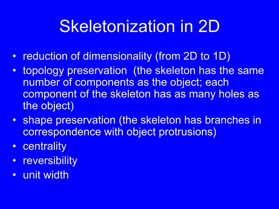
Skeletonization in 2D• reduction of dimensionality (from 2D to 1D) • topology preservation (the skeleton has the same
number of components as the object; each component of the skeleton has as many holes as the object)
• shape preservation (the skeleton has branches in correspondence with object protrusions)
• centrality• reversibility• unit width

The peeling scheme
reduction of dimensionality, with topology preservation and centrality, can be achieved by removing, border after border, all border pixels whose presence is not necessary to preserve connectedness of both the object and the background
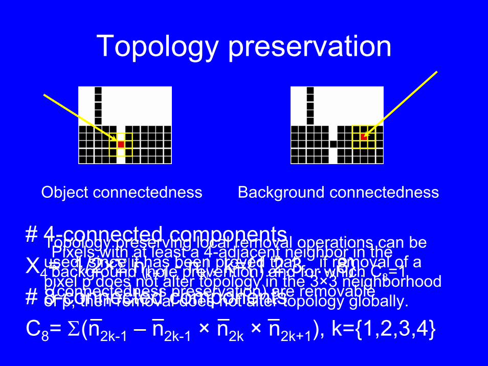
Topology preservation
Topology preserving local removal operations can be used, since it has been proved that: if removal of a pixel p does not alter topology in the 3×3 neighborhood of p, then removal does not alter topology globally.
Object connectedness Background connectedness
# 4-connected componentsX4= 1/2×Σ|nk+1 - nk|, k={1,2,3,…,8}# 8-connected componentsC8= Σ(n2k-1 – n2k-1 × n2k × n2k+1), k={1,2,3,4}
Pixels with at least a 4-adjacent neighbor in thebackground (hole prevention) and for which C8=1 (connectedness preservation) are removable

Shape preservation
End point detection:A pixel with only 1 objectneighbor is an EP
Counting the number of neighbors isnot a reliable way to identify end points

End point detection
Criterion based on the distance of border subsets from the interior
1 step of 4-expansion of the interior to select bordersubset at distance >1
2 steps of 4-expansion of the interior to select bordersubset at distance >2

“Peeling” algorithm
1. Parallelwise, identify the current border (centrality);
2. Prallelwise, mark as non removable the pixels at distance >θ from the interior (shape preservation);
3. Sequentially, delete any non marked border pixel, provided that it is removable (topologypreservation);
4. Repeat 1-3, until all no border pixel is removable.

Main disadvantageof the peeling scheme

DT-based scheme1. Compute the DT;2. Identify the pixels that belong to the skeleton.
• DT-based skeletonization is a non iterative method, producing a skeleton centered withinthe object, topologically correct, preservingshape information and reversible.
• Both the peeling scheme and the DT-basedscheme produce “nearly thin” skeletons (final thinning) and require a pruning postprocessingphase.

DT transform
• The distance transform is a replica of the image where all object elements are labelled with their distance from the background.
• The distance can be computed by usingany distance function (including the Euclidean distance)

DT of a leaf

Centers of maximal discs
• CMDs can be identified by comparing the distance label of each pixels with those of its neighbors (by taking into account the weights)
1 1 1 1 1 111 2 2 2 2 2 11 2 3 3 3 2 11 2 3 4 3 2 11 2 3 3 3 2 11 2 2 2 2 2 11 1 1 1 1 1 1
The shape of the disc dependson the selected distance.City block DT: diamondChessboard DT: square3,4 Weighted DT: polygon betterapproximating a circle
City-block DT

No need of “end point detection”

Saddle pixels
CMDsSaddle pixels
grad q = (q-p)/wi
Linking pixels

DT-based algorithm
• Compute the DT (2 scans)• Mark as skeletal pixels the CMDs, the
saddle pixels and the linking pixels (1 scanplus a path growing process)

Final thinning

Pruning
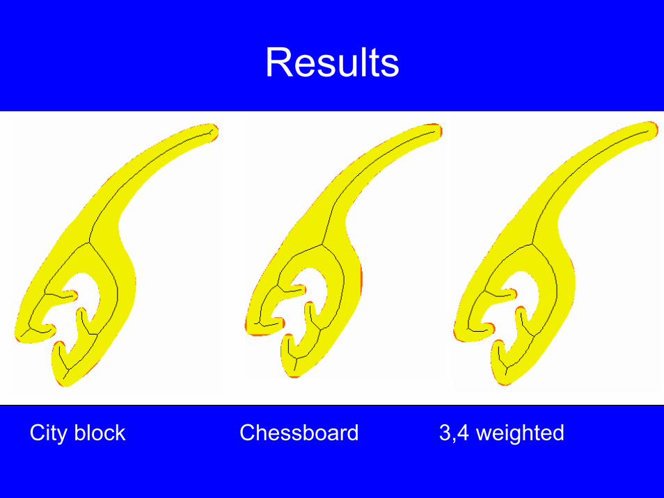
City block Chessboard 3,4 weighted
Results

Skeletonization in 3D• reduction of dimensionality (from 3D to 2D, surface
skeleton, and to 1D, curve skeleton) • topology preservation (the skeleton has the same number
of components as the object; each component of the skeleton has as many cavities and tunnels as the object)
• shape preservation (the skeleton has surfaces/branches in correspondence with object protrusions)
• centrality• reversibility• unit width

3D DT
• As in 2D, in the 3D distance transform, each object voxel is labelled with the distance to the closest background voxel
• The distance is often an approximation of the Euclidean distance
• Simplest are D6, D26
• Best metric to choose depends on the application and the methods available

D6 Distance Transform
3D equivalent tothe city-block DTThe D6 ball is an octahedron

Maximal balls in 3D
D6 D18 D26
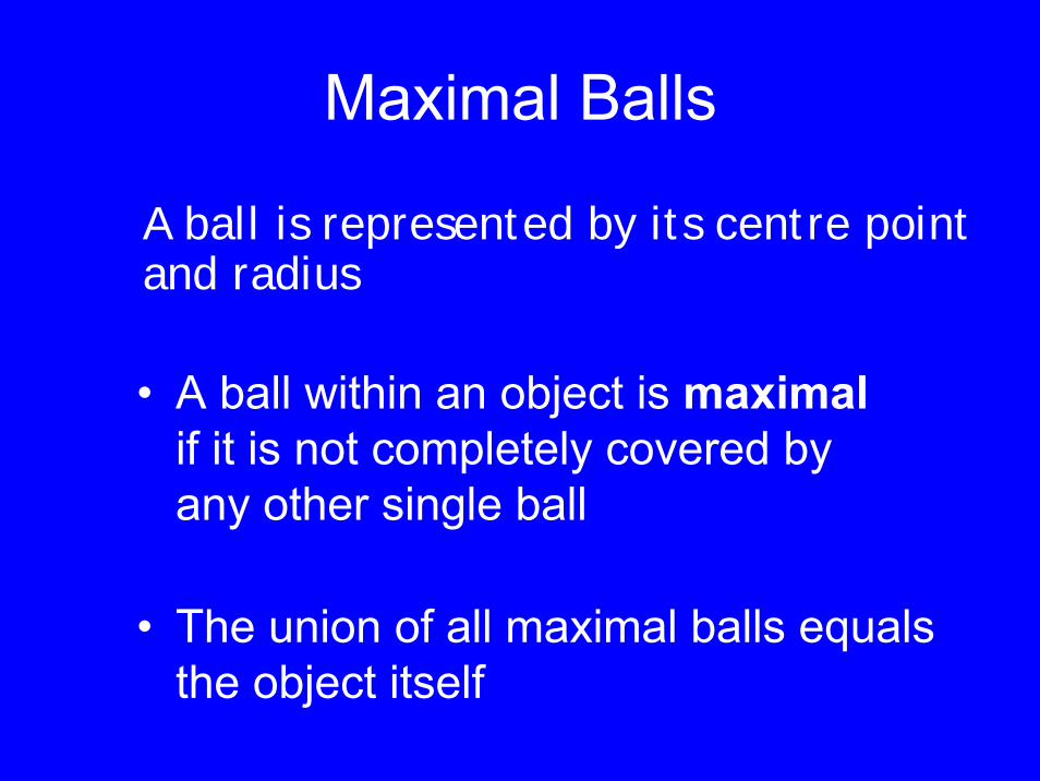
Maximal Balls
• A ball within an object is maximalif it is not completely covered by any other single ball
• The union of all maximal balls equals the object itself
A ball is represented by its centre point and radius

Original objects
CIARP’06
Centres of maximal D6 balls

Surface skeletonization
• Iterative thinning of simple voxels of the DT layer by layer
• Identify the skeletal voxels directly in the DT
Two approaches:

Simple voxels
• A voxel v is simple if its removal does not change the topology
• Count 26-connected object components in the 26-neighbourhood of v, N26
• Count 6-connected background components that are face-adjacent to v in its 18-neighbourhood, Nf
18
• A simple voxel has N26 = 1 and Nf18 = 1
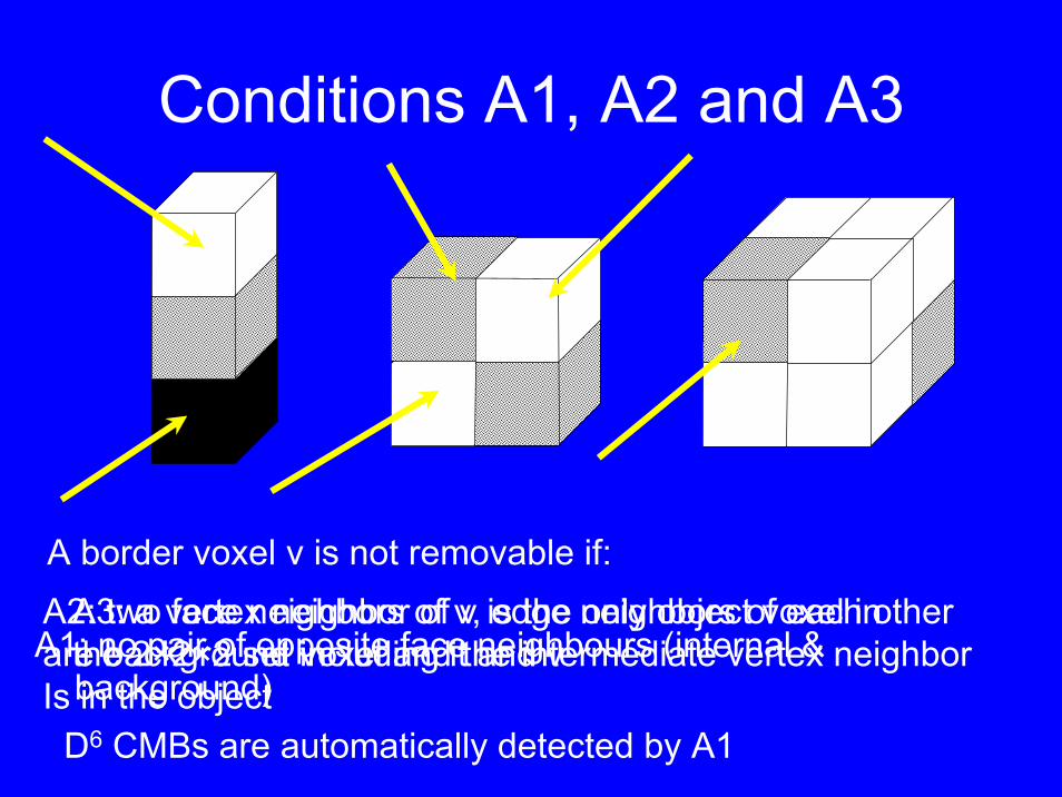
Conditions A1, A2 and A3
D6 CMBs are automatically detected by A1
A1: no pair of opposite face neighbours (internal &background)
A border voxel v is not removable if:A2: two face neighbors of v, edge neighbors of each otherare background voxel and the intermediate vertex neighborIs in the object
A3: a vertex neighbor of v is the only object voxel in the 2×2×2 set including it and v

D6 Surface skeleton


From surface skeleton to curve skeleton
Original object can not be recovered from curve skeleton
At least shape should be preserved

Preserving shape of surfaces
curves
junctions sharp corners

Surface classification
edge voxels inner voxels curve voxels junction voxels

Curve Skeletonization
• classification of surface skeletal voxels• iterative identification and removal of edge
voxels– topology preserving removal
• first step– use both initial and current classification (to
keep junctions)• second step
– use only current classification
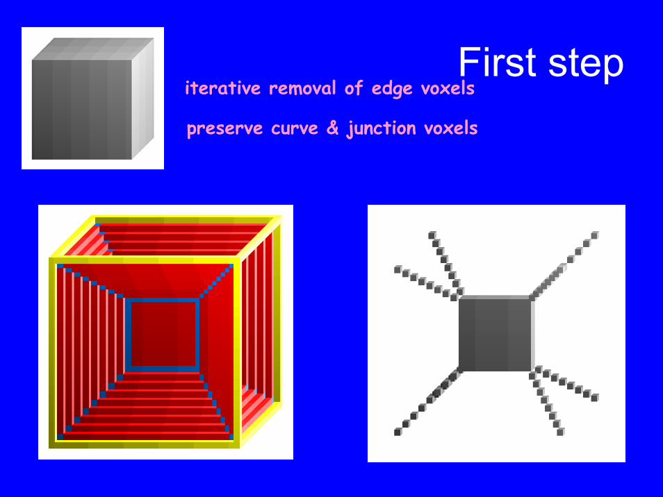
iterative removal of edge voxels
preserve curve & junction voxels
First step

Second stepiterative removal of edge voxels

object → surface skeleton →curve skeleton
object surface skeleton curve skeleton

object → surface skeleton →curve skeleton
object surface skeleton curve skeleton
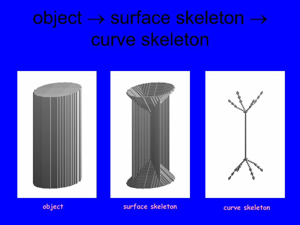
object → surface skeleton →curve skeleton
object surface skeleton curve skeleton

Final thinning
Standard topology preserving removal operations
End-point preservation directional process

Pruning
brute force information preserving

The copyright holders of The copyright holders of The copyright holders of HandHandHandare Profs. Toriwaki and Katada, are Profs. Toriwaki and Katada, are Profs. Toriwaki and Katada, Nagoya University, JapanNagoya University, JapanNagoya University, Japan


Magnetic Resonance Angiography
≈ 340 000 voxels

≈ 50 000 voxels

Final skeleton:7 000 voxels2 % of original

Questions?
Thank you for your attention

DT computation
F={1}, B={0}Forward Scan:∀ p∈F
p’= minni {ni + wi}Backward Scan:∀ p∈F
p’= min ni {p, ni + wi}
(1,∞) city-block, (1,1) chessboard, (3,4) 3,4 weighted
p
p

Reverse DT
p
p
Forward Scan:∀ p
p’= max ni {p, ni - wi}Backward Scan:∀ p
p’= max ni {p, ni - wi}

Spurious holes filling

OverviewI. Identify surface skeleton on DT
II. Simplify surface skeleton by removing short peripheral branches
III. Identify curve skeleton by classifying junctions and curves of the surfaces
IV. Reduce two-voxel ”thick” curve skeleton to one-voxel thin curve skeleton
V. Post-process the skeleton,e.g., straighten zig-zags and prune unwanted branches

DT computation in 3D
• The algorithm requires a forward and a backward scan
• During each scan:– Inspect half of the neighbours of every voxel – Propagate by increasing distance values– Choose minimum value of the current voxel
and its neighbours added by the local distances to the current voxel

Simplification of the Surface Skeleton
• Skeletonization applied to real images reveals sensitivity to noise
• Short curves in the surface border correspond to ”unsmoothness” in the original object
• Simplification method features:– Short curves are removed
– More significant curves are left untouched
• Almost complete reconstruction still possible
• Curve skeletons will have simpler structure, i.e., fewer branches

”Removal of zig-zags”

Centrality

Centres of Maximal Balls
The set of centres of maximal balls (CMBs) is a complete representation of the object
The set of CMBs may be identified on the DT:• For D6 and D26, the set of CMBs corresponds
to the local maxima• For other metrics, detection is not as simple;
especially not for the Euclidean metric

After the first phase
• a 26-connected set of voxels• at most two-voxel thick• labelled with DT values• includes all CMBs• complete object recovery possible
by growing balls of radius equal to the DT values (using the reverse distance transformation)