gas fired unit heaters models·uh100- uh140 …support.bensonheating.co.uk/archived/obsolete benson...
TRANSCRIPT

The Package Heater Company
GAS FIRED UNIT HEATERS
MODELSmiddot UH100 - UH140- UH180 - UH240- UH320
INSTRUCTION MANUAL
Fort Road Littlehampton Sussex BN17 7EF
Tel (0903) 725945
THE PACKAGE HEATER COMPANY FORT ROAD
LlTTLEHAMPTON SUSSEX BN17 7EF
Telephone (0903) 725945
INSTALLATION OPERATION COMMISSIONING AND SERVICING INSTRUCTIONS FOR PAK-A-WAY GAS FIRED UNIT HEATERS
Covers Modelsshy GC Numbers
UH100 42 675 22
UH140 42 675 23
UH180 42 675 24
UH240 42 675 25
UH320 42 675 26
THESE APPLIANCES HAVE BEEN APPROVED BY BRITISH GAS FOR USE ON NATURAL GAS
The Package Heater Company whose policy is one of continuous development and improvement reserve the right to alter any specification appearing in this manual without notification
IF IN ANY DOUBT ON THE INTERPRETATION OF ANY INSTRUCTIONS IN THIS MANUAL PLEASE CONTACT THE PAK-A-WAY SALES OFFICE ADDRESS AND TELEPHONE NUMBER AS ABOVE
CONTENTS
SECTION ONE INSTALLATION
SECTION TWO TECHNICAL DATA
SECTION THREE COMMISSIONING
SECTION FOUR SERVICING
SECTION FIVE FAULTS amp REMEDIES
SECTION SIX SPARES LIST
INDEX
lA lB lC 10 lE lF lG lH lJ lK lL 1M IN lP lQ lR 1S 1T lU lV lW 1X 1Y lZ
2 2 2 2 2 2 2 2 2
3A 3B 3C 3D 3E 3F 3G 3H 3J 3K 3L 3M
4A 4B 4C 4D 4E 4F
5A
6A 6B
DESCRIPTION PAGE NUMBERS
Introduction 3 General requirements 3 Heater unpacking 4 Warranty4 Heater positioning 5 Installation clearances 6 Heater mounting 6 Warm air distributioncirculation 6 Air supply 6 Flue installation 8 Electrical supply 9 Control panel (wiring box) 10 Time switch 10 Room thermostat 10 Room thermostat siting 11 Fan control switch 11 Limit control switch 11 SummerWinter switch 11 Flue venter 11 Venter wiring 13 Gas supply15 Operation on LPG15 Fitting LPG burner conversion sets 16 LPG gas pressure settings 17
Natural Gas pressure settings 18 Injector size chart 18 Performance 19 Dimensions19 Weights 19 Mounting heights 20 Gas control valve data 20 Pilot 21 Thermocouple 21
Electrical installation (General) 22 Gas installation (General) 22 General installation checks 22 Lighting and pilot commissioning 22 Main burner commissioning 23 Testing the air heater 24 Air heater operation cycle 24 Gas control valve - Warning 24 Air distribution - Adjustment 25 Users instructionsAdvice to user 25 Service and spares Advice to user 25 General lighting instructions 25
General 27 WARNING 27 Service instructions 27 Re-commissioning29 Service report 29 Burner removal (photograph) 29
(j)Pilot problems 30 (ii)Burner problems 30 (iii)Fan problems 31
Spares UH100-UHl40-UHl80 32 Spares UH240-UH320 33
SECTION SEVEN 23301 EUH Air heater (internal) 34 WIRING DIAGRAMS 0998 EUH (24v) 0999 EUH (240v)
External controls (thermostats timeswitches SummerWinter switches 3536 23302 EUH Flue venter 37
2
SECTION ONE
INSTALLATION
1A INTRODUCTION
PAK-A-WAY Model U H air heaters are compact natural draught gas fired automatic horizontal heaters range rated with outputs between 293 kw (100000 Btuh) and 937 kW (320000 Btuh) Natural Gas units supplied unless otherwise specified They are equipped with powerful axial fans fitted at rear of heater and are primarily intended for heating commercial or industrial premises
They can be suspended anywhere in the space to be heated from hangers provided on cabinet top or can be mounted on non-combustible supports where they heat the flow of circulating air controlled in elevation by adjustable horizontal louvres
A socket for sheet metal flue systems i~ provided on top or can be site interchanged to give a rear flue outlet Built in aluminised steel draught diverter is integrally mounted within the air heater Each air heater must be connected to an individual open flue system
The enclosed controls and removable burner rack assembly are accessible through a removable side panel Standard units are equipped with a low voltage control system and thermocouple actuated safety relay with manual reset button on the electro magnetic gas control valve
Cabinet is made of cold rolled phosphate treated steel panels and corner sections Finish stove enamel PAK-A-WAY blue Heat exchanger fitted as standard is multiple all welded aluminised steel
These instructions are intended to provide a guide to the procedure for a systematic check up of the installation arrangements and of possible faults in the air heater arising during the handling and installation
It is recommended that this check up be carried out during andor at the completion of the installation and should not wait until the air heater is actually required so that any work needing attention can be carried out in ample time
Whilst in most cases all will be found to be in order this check up will save a great deal of time and expense in tracing any faults which may exist
When installing PAK-A-WAY gas fired Unit Heaters the following points require to be carefully considered
(a) Position of air heater for the distribution and general circulation of warmed air
(b) Air Heater mounting height level If it is found that site circumstances require a higher mounting height than that recommended elsewhere in this manual it may be possible to overcome the stratificationcirculation problems which will generally occur with high level mounting by using a PAK-A-WAYRECOUPAK Energy saving fan system in conjunction with the heating installation Contact the Package Heater Co Ltd Sales office for further information
(c) Ensure that the air heater position and mounting height allows for safe service and maintenance access and for adequate clearance for removal of the burner tray assembly and fan assembly if required
(d) Position of air heater for flue route
(e) Position of air heater for gas pipe route
(f) Position of electrical fused isolator timeswitch thermostat etc in relation to area being heated and routing for wiring back to air heater
ALL PAK-A-WAY GAS FIRED UNIT HEATERS MUST BE COMMISSIONED TEST FIRED AND SERVICED BY A COMPETENT GAS ENGINEER
1B GENERAL REQUIREMENTS
SAFETY NOTE
The installation of the air heater(s) must be in accordance with the relevant requirements of the GAS SAFETY REGULATIONS BUILDING REGULATIONS and the IEE REGULATIONS
It should be in accordance also with any relevant requirements of the LOCAL GAS REGION LOCAL AUTHORITY and FIRE AUTHORITY and the relevant recommendations of the following documents
3
BRITISH STANDARD CODES OF PRACTICE
CP 331 Installation of Pipes and Meters for Town Gas Part 3 Low pressure installation pipes CP 3 Ch IV precautions a~ainst fire Part 2 Shops and Departmental Stores Part 3 Office Buildings and the relevant standards of the following document
Standards of Installation for Gas Fired Industrial Warm Air Heaters (published by the Industrial Warm Air Heater Manufacturers Association Limited)
Where air heaters are used in installations where the total input is less than 60 kW then
BS5864 Installation of gas-fired ducted-air heaters of rated input not exceeding 69 kW and BS5440 Flues and air supply for gas appliances of rated input not exceeding 6OkW Part 1 Flues Part 2 Air supply
must also be followed
The above related documents are from time to time revised and additional documents published Whilst every effort is made to keep literature current Package Heater Co Ltd cannot be responsible for this listing being correct or complete at the time of issue
Account must also be taken to ensure that installation is carried out in strict accordance with any insurance companys requirements appertaining to the area in which the air heater(s) is located
The air heater must not be installed in conditions for which it is not specifically designed eg where the atmosphere is highly corrosive or salty and where high wind speeds may affect the burner operation
Suitable protection should be provided for the air heater(s) when they are located in such a position that external mechanical damage may be sustained due to such things as fork lift trucks or overhead cranes
1C HEATER UNPACKING
Whilst every care is taken to ensure that the air heater(s) is delivered in good condition upon receipt an immediate inspection should be carried out to check for any damage which may have been incurred in transit If any damage is found it should be reported to the Package Heater Co Ltd Sales Office within TWO working days of delivery and must be immediately confirmed in writing otherwise claims will not be accepted The heater(s) has been fired on Natural Gas and inspected at the factory immediately prior to being crated and packed and was in good condition at that time
The heater is supplied mounted upon a wooden pallet with timber packing to protect the fan cage and is enclosed within a cardboard carton which is held with securing bands
To prevent scuffing of the paintwork on the base do not remove air heater from pallet (to which it is secured by means of two metal clips and coachscrews) until heater is positioned if suspended from eyebolts or immediately prior to positioning on a non combustible surface or metal cantilever brackets
To unpack the heater cut the securing bands remove all staples holding carton to pallet and timber packing lift carton upwards and clear to expose the timber corner packing which can then be removed
Check that the air heater is correct as described on the delivery note and with the order requirements
The air heater can now be moved on the pallet to its installation location
To remove air heater from pallet unscrew the two coachscrews passing through the brackets into the wooden pallet take out the two setscrews (one on each bracket) from the heater base remove brackets Ensure setscrews are replaced immediately in heater to properly support corner legs and base panel
NOTE PAK-A-WAY UH Air Heaters are supplied suitable for firing on NATURAL GAS ONLY as standard If units are required to be fired on an LPG gas then they must be converted prior to installation with a suitable conversion set supplied loose and sent separately as an extra For further information please contact the Package Heater Co Limited Sales Office (See this manual for information required)
Heaters are supplied with a loose gas cock tied to the gas burner manifold inside the heater casing adjacent to the gas valve An adaptor plate for converting the vertical flue socket spigot to horizontal outlet is also supplied loose attached to the wooden pallet
10 WARRANTY
Please refer to the Conditions of Sale printed on the reverse side of the Sales Acknowledgment copies of which can be supplied separately if requested from the Package Heater Co Sales Office
4
Warranty is void if
(a) Installation is not in accordance with the Codes and Standards listed in Section 1 B General Requirements of this manual
(b) The flue arrangement and air supply for the heater is not in accordance with the recommendation or codes of practice referred to in this manual
(c) Air through heater is not provided in accordance with the technical specifications on the heater data plate
(d) Internal wiring on heater has been modified middotby user installer or service undertaken without PAK-A-WAY permission andor written agreement
(e) Heater is operated in the presence of Chlorinated Vapours or corrosive atmospheres eg degreasing plant certain types of paint acids or high salt concentrations
(f) The low voltage (24 volt) controls have been subjected to mains voltage
(g) The heater has been switched on and off via a timeswitch wired incorrectly according to the wiring diagram supplied with this manual or heater wiring diagram
(h) The main electrical supply input to the air heater has been switched on and off by other methods to control heater eg switched on and off via isolator or a plug
(j) Heater has been affected by the ingress of water in any form
If a CLAIM UNDER WARRANTY is made then the following information is required to enable a replacement to be supplied
(j) Heater serial number (ii) Heater GC number (iii) Heater model
(This information ie (i) (ii) and (iii) above can be found on the Data plate affixed to the cover of the wiring box which is inside the service access panel of heater)
(iv) Original order reference (where known) or approximate date of supply and full site address and installers name and address (v) Information and symptoms regarding the alleged fault
Warranty on heater parts is twelve months from date of delivery unless a specific part is guaranteed for a longer period by the manufacturer when the applicable extra period will apply
FAULTY PARTS MUST BE RETURNED TO THE PACKAGE HEATER CO LIMITED SALES OFFICE ADDRESS AS LISTED INSIDE THE FRONT COVER OF THIS MANUAL FOR INSPECTION TO VERIFY THE CLAIM (UNLESS SPECIFICALLY REQUESTED TO BE SENT TO OUR WORKS)
Note Notification is required immediately a fault is suspected otherwise no responsibility can be taken for further damage or expense incurred if other means are used to carry out rectification works
1EHEATER POSITIONING
For best results the air heater(s) should be placed with certain rules in mind In general a heater should be located from 183 metres to 305 metres (6 to 10 feet) to the underside of base from factory floor level according to size to utilize the maximum effect of air throw (Refer to Technical Data section elsewhere in this manual)
The location chosen for the air heater must allow for the fitting of an effective flue system and provide adequate clearance for ~ir supply return air circulation gas supply electrical supply and service access
I
Suspended air heaters are most effective when located as close to the working area as possible and this fact should be kept in mind when determining the mounting height to be used However care should be exercised to avoid directing the discharged air directly onto the room occupants
Atthose points where infiltration of cold air is excessive such as at entrance or loading doorways it is desirable to locate the air heater so that it will discharge towards or preferably across the source of cold air from a distance of approximately 15 to 6 metres (5 to 20 feet) dependant upon doorway size and air throw of heater chosen
Air heaters should be arranged to discharge toward or along exposed wall surfaces if possible Where two or more units are employed in the same room a general scheme of air circulation should be maintained for the best results
5
1F INSTALLATION CLEARANCES
The air heater(s) must be installed taking into account the following minimum clearances to allow for safe installation from combustible surfaces and servicing
FRONT - 150 mm (6 inches) REAR - 600 mm (24 inches) from rearmost point of heater TOP - 600 mm (24 inches) LEFT - WIDTH OF HEATER - PLUS 300 mm (12 inches) Refer to Technical Data Section (for width dimension)
elsewhere in this manual RIGHT - 600 mm (24 inches)
Note When referring to left and right hand side of air heater it is assumed that the discharged air from the heater is blowing towards the face of the viewer
These distances apply to wall mounted or suspended air heater installations
Any combustible material adjacent to the air heater(s) andor flue system(s) must be so placed or shielded as to ensure that its temperature does not exceed 65 deg C (150 deg F)
1G HEATER MOUNTING
The air heater(s) must be installed so that they are level and rigidly fixed All suspension andor supporting materials must be non-combustible and capable of withstanding the effects of corrosion
The air heater(s) may be suspended from the eyebolts provided on top of heater cabinet using chains cables straps or rods ensuring that all four suspension points fitted are utilized and the weight evenly distributed or may be mounted supported on or from steel brackets Alternatively the air heater may be positioned supported on a flat roof area such as over an office storeroom etc In this case they may be mounted on a non-combustible surface which is capable of adequately supporting the weight of the heater and any ancilliary equipment Check the heater weight from information supplied in the Technical Data Section elsewhere in this manual
Attention should be paid to ensure full access is still retained for servicing eg air heaters should not be fitted inside an angle iron frame which would prevent full service access and removal of burner tray In particular that no hazard will be presented to personnel working below or in the vicinity or to personnel employed to carry out any service work on the air heater
Each of the provided eyebolts has a thread size of 8 mm with an overall dia of eyebolt 36 mm and internal diameter of 20 mm
1H WARM AIR DISTRIBUTIONCIRCULATION
The temperature rise through the air heater is approximately 40 deg C (72 deg F) The air heater(s) should be positioned to enable maximum circulation of discharged warm air within the area to be heated whilst taking into account personnel in working areas sources of cold air ingress and obstructions to circulation
Recommendations for the air distribution are given in the document entitled Standards of Installation for Gas Fired Industrial Warm Air Heaters (published by the Industrial Warm Air Heater Manufacturers Association Limited)
The following notes are of particular importance
A full and unobstructed return air path to the air heater(s) must be provided
Care must be taken when air heaters are used to blow through wall openings to ensure that return-air intakes are kept clear of sources of smells and fumes In special circumstances where there is any possibility of pollution of the air by dust shavings etc precautions must be taken by carefully positioning return-air intakes from the area being heated
Where there is a risk of combustible material being placed close to the warm air outlets suitable barrier rails should be provided to prevent any combustible material being within 910 mm (3 ft) of the outlets
1J AIR SUPPLY
The following notes are intended to give general guidance In all cases there must be provision for an adequate supply of air for both combustion and general ventilation
6
Where the air heater(s) is to be installed in the space to be heated the air heater(s) requires the space containing it to have a permanent air vent direct to outside air The air vent should have negligible resistance and must not be sited in any position where it is likely to be easily blocked or flooded or in any position adjacent to an extraction system which is carrying flammable vapour
NOTE If a PAK-A-WAY unit heater is installed in a room equipped with an air dust fume extraction system or a flue venter fan(s) fitted then the permanent air vents must be sized to take this into account and allow for the required air changes
The basic minimum effective area requirement of the air vent is as follows
TOTAL INPUT RATING AI R VENT AREA OF AIR HEATER INSTALLATION (Air direct from outside)
Up to 730 kW 45cm 2 per kW (Up to 2500000 btuhr) (1 in2 per 5000 btuhr)
730 kW to 1320 kW 3300 cm2
(2500000 to 4500000 btuhr) (500 in2 )
Above 1320 kW 25 cm2 per kW (Above 4500000 btuhr) (1 in2 per 9000 btuhr)
NOTE The above requirements do not allow for any air extraction allowances
r-A LL ~
-shy 9 rEt ~V-~I r - - - 1 s ie 2~ ~
~ ~
~ ~ ~ -
AIR VENT DIRECT TO OUTSIDE
~ -fshy
~ [ - -- - - ~ bull J
The air supply requirement stated above is related to the maximum rated heat input of the air heater installation
7
AIR SUPPLY REQUIREMENTS FOR SINGLE HEATER INSTALLATIONS
LOW LEVEL RETURN AIR VENTILATION REQUIREMENTS
FREE AREA OF VENT FREE AREA OF RETURN HEAT INPUT TO OUTSI DE AI R INTAKE AIR FOR CIRCULATION
HEATER MODEL kW Btuh cm2 ins2 cm2 ins2
UH100 381 129900 171 27 18840 2300
UH140 533 181800 239 37 20440 3168
UH180 685 233800 311 48 26000 4030
UH240 913 311)00 410 64 352~0 5470
UH320 1218 415600 549 85 46450 7200
Where two or more heaters are installed in the same room the aggregate input rating should be used for sizing the air vents
NOTE IT IS IMPORTANT THAT THESE AREAS ARE ADHERED TO PREVENTING NEGATIVE PRESSURES IN PLANT ROOM
----_____-11 R ETUR N AI R
1K FLUE INSTALLATION
It is essential that the products of combustion be flued to the outside of the building The air heater(s) must be installed with a flue range correctly sized and fitted with an approved flue terminal (the conical cap is not recommended) ensuring that care is taken to comply with all necessary regulations regarding flue height and materials used (See BS5440 Part 1)
If asbestos or spirally wound metal flue pipe is used then a suitable flue socket adaptor which increases the size of the flue outlet accordingly must be used The Package Heater Co Ltd will generally be able to advise a recommended source from which these can be obtained
Note Asbestos flue pipe is not recommended for suspended units and should only be used when the heater is rigidly supported
The following general recommendations apply to satisfactory flueing of the air heater(s)
1 All PAK-A-WAY UH air heaters are equipped with a built in down draught diverter which prevents the recirculation of combustion products Conseauently an external draught diverter barometric damper or antispiliage system must not be installed All PAK-A-WAY UH air heaters are designed so that such devices are unnecess~ry No internal alteration should be made to the built in down draught diverter A minimum of 150 mm (6 ins) unobstructed clearance is required in front of the heater to allow for correct operation of the draught diverter
2 If units are to be used to blow through a wall opening ensure at least 150 mm (6 ins) clearance in front of the heater to allow for the correct operation of the draught diverter A stub duct should be positively fitted and sealed at connection to heater and around wall opening Adequate return air facility must be provided (See section 1J)
8
3 The interchangeable flue outlet on the PAK-A-WAY UH air heaters can be fitted to provide a horizontal rear outlet as required on site instead of the vertical outlet which is fitted as standard (Refer to technical data section for outlet positions supplied elsewhere in this manual) To change fitting unscrew the flue socket plate from air heater position the supplied adaptor plate with open end towards rear of heater and refit screwsRe-position the flue socket plate in horizontal outlet position and replace the fixing screws
4 The vertical height of the flue measured from the flue socket outlet of the air heater to the outside terminal should be a minimum of 18 metres (6 ft) in order to provide an adequate natural draught The temperature of the products of combustion leaving the heater is approximately 260 deg C (500 deg F) hence they rise naturally in the flue therefore unnecessary bends and obstructions should be avoided If this is inapplicable the installation of a flue venter fan should be considered which can be supplied by PAK-A-WAY (see separate section 1 U in this manual for the fitting and wiring of flue venter fans)
NOTE If a flue venter fan is used the flue size from the venter is decreased
ie UH100 amp UH140 4 ins dia (100 mm dial Flue UH180-UH24O-UH320 6 ins dia (150 mm dial Flue
5 Horizontal runs of flue should be avoided wherever possible A near horizontal run of 3 metres (10 ft) maximum should not be exceeded A positive rise in the direction of the flue gasses to be evacuated of 65 mm (22 ins) per 300 mm (12 ins) of horizontal run is recommended Where near horizontal flues are used the vertical height must be a minimum of one and a half times the horizontal length A ratio of twice vertical height to once horizontal length is more desirable (If in any doubt on this please consult the PAK-A-WAY Sales Office - telephone number at the front of this manual) Flue pipes must not have sharp bends Easy obtuse bends are necessary to assist the flow of gasses
6 Allowance should be made for the disconnection of the flue range(s) from the air heater(s) for inspection and servicing purposes Where it is considered appropriate bends should be fitted with removable access covers for inspection and cleaning purposes
7 The flue system(s) should ensure for the safe and efficient operation of the air heater(s) to which attached Termination should be in a freely exposed position and must be so situated as to prevent the combustion process being affected by wind allow for the dispersal of combustion products to open air prevent the products of combustion entering any opening in a building in such concentration as to be prejudicial to health or a nuisance
8 The flue pipe(s) should be connected to a permanent chimney or extended through a roof or wall and extend at least 1 metre (3 ft) above any obstruction within 3 metres (10 ft) of the outlet
IT IS IMPERATIVE THATWHEREFLUE PASSES THROUGH ROOF THIS OPENING IS PROPERLY SEALED BY A ROOF FLASHING PLATE AND CRAVAT TO ENSURE NO WATER ENTERS
NOTE CLAIMS FOR ANY DAMAGE RESULTING FROM THE INGRESS OF WATER WILL NOT BE CONSIDERED
Combustion products contain water vapour which may condense out in the case of long or exposed flues Prevention of condensation within the flue should be an important factor in the design of a flue system
Where a flue system is passing through an unheated area or is sited in an exposed position these sections may be fitted with a twin wall flue to minimise condensation
NOTE If a twin wall flue is used it should be of a type acceptable to BRITISH GAS and a suitable adaptor(s) will be required
Where condensation in the flue is unavoidable provision should be made for condensate to flow freely to a point at which it can be released preferably into a gully The condensate pipe from the flue to the dispersal point should be of non corrodible material of not less than 22 mm (34 in) diameter
1L ELECTRICAL SUPPLY
ALL ELECTRICAL WIRING AND CONNECTIONS MUST BE MADE IN ACCORDANCE WITH THE IEE REGULATIONS CHECK ANY LOCAL REGULATIONS THAT APPLY
WARNING ENSURE THAT ELECTRICAL SUPPLY AND GAS SUPPLY ARE TURNED OFF BEFORE ANY WORK IS CARRIED OUT ON AIR HEATER TO CHECK WIRING
The main 240 volt and 24 volt control wiring must not be run within the same conduit multi-core cable or mineral insulated Pyro cable Voltage pick-up may occur leading to air heater malfunction andor permanent damage to the heater control system
The main electrical supply must not be switched OFF to the air heater to stop it (allowing overheating to occur with subsequent damage to the air heater or controls) except in an emergency or when air heater has sufficiently cooled for servicing purposes
9
NO CLAIMS FOR ANY DAMAGE WILL BE CONSIDERED RESULTING FROM (a) INCORRECT WIRING OR OPERATION AS ABOVE (b) WHERE THE HEATER 24 VOLT CONTROLS HAVE BEEN SUBJECTED TO MAINS VOLTAGE
(I) Each air heater will require a permanent 220240 volt 50 cycle electrical supply which must be wired through a 13 amp or 15 amp electrical fused isolator fitted with a fuse rated at 5 amps The correct supply connection points for the live neutral and earth are clearly indicated on the wirino diaaram mounted inside the wiring box cover olate fittprJ inside heater being the first three terminals respectively from left to right numbered 1 L 2N and 3E (see wiring diagram supplied elsewhere in this manual)
(II) The isolator should be mounted adjacent to the air heater in an easily accessible position to allow for service isolation or emergency shut-off of electrical supply
(III) External wiring should be run in 1mm 2 insulated cable with a copper conductor (or equivalent) based upon a volt drop per ampere per metre of 40 mVTotal volt drop must not exceed 25 of the nominal voltage Conduits should be positioned to ensure that they do not interferemiddot with service access to heater and be properly secured
Terminals 11 and 12 have been bridged to facilitate operation without a 24v thermostat Terminals 5 and 6 have been bridged to allow operation without a timeswitch or a 240v thermostat
(IV) On no account should more than one air heater be connected to a single thermostat or timeswitch
NB The exception to this is when a control box (see note following) supplied by the Package Heater Co Limited suitable for controlling one to four or five or six air heaters is employed Then the air heaters must be wired in accordance with the multi-heater wiring diagram supplied with the control box read in conjunction with the wiring diagram on air heater wiring box cover or supplied with this manual
NOTE The control box for use with multi-heater installations is not included in the British Gas Approval of this appliance
t CARE MUST BE TAKEN TO ENSURE THAT ANY WIRING DOES NOT LIE AGAINST ANY METAL SURFACES LIKELY TO GET HOT CAUSING THE INSULATION TO BREAK DOWN RESULTING IN SUBSEQUENT SHORT CIRCUITING CAUSING DAMAGE TO HEATER CONTROLS
1M CONTROL PANEL [WIRING BOX]
Remove the service access panel (refer to service section for details) Check the air heater DATA PLATE (fitted on wiring box ccver) to ensure that the su)olv voltaqe and current requirements are correct PAK-A-WAY heaters are fitted with a double wound transformer with a secondary output of 24 volt to supply the low voltage burner controls and gas control valve
Unscrew the two screws retaining wiring box cover and remove Check all wiring connections for security that no loose strands of cable wire are near or bridging across terminals Ensure that all cables are clear and secured Especially ensure that cables are not resting against back panel of wiring box adjacent to heat exchanger which can get hot from radiated heat Check that the fitted 2 amp internal fuse is secure and is not blown or broken
Ensure that all external controls are wired up in accordance with the appropriate wiring diagrams (See this manual andor wiring diagrams supplied with controls)
1N TIME SWITCH
Where fitted if wired into the 24 volt circuit (ie across terminals 11 and 12) supplying the low voltage controls must have separate motor and load connections If a time switch is used having a common motor and load supply then it should be wired with the switched contacts operating across terminals 5 and 6 in the heate~ control panel wiring box (see wiring diagram supplied with this manual)
The time switch manufacturers instruction leaflet should be consulted and adjustment made for correct ONOFF sequence day omission and early off as required by client or user
1P ROOM THERMOSTAT
IF THERMOSTAT USED WITH THE AIR HEATER IS 24 VOLT AND IS FITTED WITH AN ANTICIPATOR THE LOAD CURRENT RATING REQUIRES TO BE ADJUSTED TO A SETTING OF 03 AMPS UNLESS A FLUE VENTER [SEE SECTION 1U]IS FITTED TO AIR HEATER WHEN A SETTING OF 0425 AMPS MINIMUM IS REQUIRED It must be wired in conjunction with the directions enclosed with thermostat and wiring diagram fitted in air heater or supplied with this manual
NOTE 24 VOLT EXTERNAL WIRING MUST BE WIRED IN ACCORDANCE WITH IEE REGULATIONS SEPARATE FROM AND TO THE MAIN 240 VOLT WIRING
10
1Q ROOM THERMOSTAT SITING
The selection of the correct position for the room thermostat(s) is particularly important and should be sited at a point which will be generally representative of the heated area(s) as far as temperature is concerned
Draughty areas or areas subject to direct heat eg from the sun in direct line with air heater discharge where air movement is relatively stagnant such as recesses are all positions to be avoided
The thermostat should generally be mounted at a height of approximately 15 m (5 feet) from the floor
1R FAN CONTROL SWITCH
The fan control switch (normally open 240 volt contacts) is wired to control the live supply to the fan motor(s) The circuit is made and fan(s) switched on when the anticipator prewired from the low voltage 24 volt burner control circuit heats up and closes the fan switch 240 volt contacts When the thermostat is satisfied or timeswitch shuts down burner the fan is delayed from shutting down until the thermal switch has cooled sufficiently so as radiated and convected heat from the heater structure does not damage controls
The fan control switch provides the following
1(a) Delay of fan operation preventing initial circulation of cold air
(b) Fan operation as long as the unit is hot
2 Additional safety by keeping the fan in operation in the event that the gas control valve fails to close when the thermostat is satisfied
To be sure that the fan(s) can continue to operate the power supply to the air heater must not be interrupted except when servicing the air heater or in an emergency
If the user requires to turn the air heater off at night then the gas valve circuit should be opened by a single pole switch summerwinter switch or timeswitch wired in as per wiring diagram supplied with this manual
1S LIMIT CONTROL SWITCH
A non adjustable (normally closed contacts) high temperature limit switch is fitted pre-wired into the burner control 24 volt circuit which is set to open at an air temperature of 87 deg C (189 deg F) This will shut off the gas valve in the event of fan motor failure or if the outlet air temperature should exceed safe limits
One limit stat is fitted to the air heater(s) for each fan motor fitted ie UH1()()-UH14O-UHl80 each have one only and UH24O-UH320 have two fitted
1T SUMMERWINTER SWITCH [where fitted)
SummerWinter switches can be supplied loose as an extra if required This is a make or break switch with three positions WINTER - for heating circuit OFF SUMMER for fan ventilation only
It should be wired into the 240 volt control circuit as shown on the wiring diagram supplied with this manual and as follows
Pole 1 - TERMINAL CONNECTIONS
A Connections 2 and 4 are common If timeswitch fitted then outlet side from switched connection should be wired to either terminal 2 or 4 on summerwinter switch
If no timeswitch is fitted then connection direct from terminal 5 in heater wiring box
B WINTER POSITION Terminal 1 (outlet) should be connected to terminal 6 in heater wiring box (This controls the burner circuit)
C SUMMER POSITION Terminal 3 (outlet) should be connected to terminal 4 in air heater wiring box (This provides a live supply direct to the fan motor(s) overriding the fan control switch to provide ventilation only during the summer)
1U FLUE VENTER
Note The Flue Venter is not included in the British Gas Approval of this appliance
1 1
Flue venters can be supplied loose as an extra if required
A flue venter may require to be fitted to provide extraction for the products of combustion where
a Horizontal flue runs are being used b Flue resistance requires fan assistance
NOTE When a venter is fitted the outlet flue diameter (from venter) internal diameter is reduced to the sizes shown below
UH100-UH140 - 4 ins dia (100 mm) Flue UH180-UH240-UH320 - 6 ins dia (150 mm) Flue
An approved pattern flue terminal is required to be fitted at flue outlet external to the building
MAXIMUM FLUE LENGTHS WITH VENTER FITTED
UH100 = (30 m) 100 ft Flue dia (100 mm) 4 ins
UH140 = (23 m) 75 ft Flue dia (100 mm) 4 ins
UH180 = (11 m) 35 ft Flue dia (150 mm) 6 ins
UH240 = (26 m) 85 ft Flue dia (150 mm) 6 ins
UH320 = (28 m) 92 ft Flue dia (150 mm) 6 ins
Reduce these lengths by the following amount for each fitting as fitted
1350 BEND = less (15 m) 5ft
900 BEND = less (3 m) 10ft
GLC Term inal = less (3 m) 10 ft
The venters are supplied loose together w ith a flue socket reducing adaptor plate and a make up blanking plate to suit the model of Unit Heater to which they are to be fitted
To fit a venter unscrew the sheet metal screws holding flue socket plate fitted at top rear of air heater and remove Place the horizontal flue outlet adaptor plate (supplied loose with air heater) on top of air heater with open end at rear and replace screws to fix Position the venter flue spigot adaptor plate onto the air heater with spigot facing rearwards and outlet horizontal place the blanking plate in position to seal off the flue outlet and fix them in place with the provided sheet metal screws The venter can now be fitted to the air heater
The venter inlet should be fitted directly onto the spigot adaptor plate outlet at rear of the air heater The outlet position from the venter can either be placed horizontally so that the flue will then pass out on the right hand side of heater or placed to allow flue to rise vertically (see following diagram) and fixed in position
NOTE The venter must not be fitted directly onto the top of air heater as this can give rise to problems with overheating of the venter fan motor and wiring
NOTE THE VENTER MUST ONLY BE FITTED SO THAT THE AXIS THROUGH MOTOR SHAFT IS IN A HORIZONTAL PLANE
12
INCORRECT INSTALLATI ON CORRECT INSTALLATION
RECOMMENDED CORRECT INSTALLATION
Venter spigot adaptor plater~~ I I
I Blanking plate
Horizontal flue outlet adaptor plate
(Venter fitted directly to rear of heater)
1V VENTER WIRING
HEATER INTERNAL WIRING ALTERATIONS
Refer to the wiring diagrams elsewhere in this manual
When fitting venter to PAK-A-WAY UH Air Heater(s) the internal wiring must be altered as follows
(a) The overtemp limit control switch lead(s) fitted into terminal 11 on the terminal strip inside wiring box should be connected into terminal 8 instead
(b) The terminal numbers in venter are wired to the corresponding numbered terminals in the heater wiring box
(c) If heater is to be fitted with a timeswitch then the switched contacts should be wired across terminals 5 and 6 in heater wiring box ie the primary mains electrical Jive supply to transformer
(d) Thermostat where fitted 24 volt stat with an adjustable load amperage setting for anticipator should be set at 0425 amps minimum
13
VENTER TERMINAL WIRING GUIDE
HEATER TERMINAL VENTER TERMINAL
240 volt 6 Live feed in 240 volt 6
Venter motor 2 Neutral 2
Supply 3 Earth 3
24 volt 11 Live feed in 24 volt 11
Gas control valve 8 Live feed out 24 volt 8
Supply 9 Earth 9
IMPORTANT
changed from terminal 11 See previous head ing Heater I nternal Wiring Alterations paragraph (a)
PRE-INSTALLATION CHECK
The air flow switch (A) is a small spring loaded switch normally in an off position until the actuating button under the hinge (8) is depressed to close the circuit It returns to the off position when the button is released A flat blade (e) hinged at the back of the button (8) crosses the button and is extended into the air stream of the venter The venter fan is started via the thermostat circuit which energises a relay fitted in venter closing the 240 volt circuit to the venter motor When the air fan reaches velocity the air flow switch blade is pushed back against the button closing the circuit to the gas valve solenoid
The air flow switch blade extends through an opening (D) in the connection box (where it is located) and is bent to a 90 deg angle (E) and then extends into the fan housing through a 6 mm (14 inch) wide slot The angle of the 90 deg bend must be adjusted by bending backward or forward so that the switch can fully open or close
A definite click is heard both when the switch opens and closes In the open position (when the switch button is depressed) a full 08 mm (132 ins) clearance should be provided after the click is heard If that is not the case bend the blade back at the angle until proper clearance is provided
When the blade is released the off click must occur before the blade is fully returned to its rest position against the side of the slot in the fan housing
14
1W GAS SUPPLY
The local GAS REGION is responsible for supplying and installing the service pipets) and gasmeter(s) If a gas supply andor meter is not present then they must be consulted to ascertain the availability of an adequate supply of gas for the proposed installation
Where a gas supply and meter is present then the existing meter should be checked preferably by the GAS REGION to ensure that the meter and service pipe is adequate to deal with the rate of gas supply required
At the planning stage of each installation the local GAS REGION should be consulted They will advise as to the pressure of gas supply recommended pipe sizes and allowable pressure drop for single and multi-heater installations
The gas pipework from the meter must be fitted and supported in accordance with CP3313 and should be sized to produce the required gas volume to each air heater so that at least the minimum inlet pressure (see this manual or air heater data plate) is obtained to the burner manifold inlet to give the required burner running pressure An approved gas jointing compound must be used Pipework smaller than the air heater gas inlet connection size must not be fitted Gas connection should be made to the air heater through the hole provided in air heater(s) top panel which is vertically above the burner manifold inlet connection
The provided union fitted on burner manifold inlet connection should be left in its present position internally within the air heater casing as it will be required as a separation point when removing the burner for service or maintenance
Each PAK-A-WAY air heater is supplied with a loose gas isolating cock (usually found tied to the burner manifold inside service panel on air heater) Care should be taken when fitting to use correctly sized spanners only without undue force to prevent the possibility of distortion with subsequent gas leakage After fitting the gas cock it sould be opened and closed by hand to ensure that it operates freely
EACH AIR HEATER MUST BE FITTED WITH A GAS SUPPLY ISOLATING COCK AND A SUITABLE UNION MOUNTED OUTSIDE HEATER CASING POSITIONED TO ENABLE SERVICE ACCESS THE COCK TO BE UPSTREAM AND ADJACENT TO THE UNION WHICH IN TURN MUST BE UPSTREAM OF THE BURNER INLET
Check that the type of gas to be used is correct for the burner
NOTE PAK-A-WAY UH HEATERS ARE ONLY SUPPLIED FITTED WITH INJECTORS SUITABLE FOR USE ON NATURAL GAS AS STANDARD CONVERSION SETS FOR OTHER TYPES OF GAS ARE AVAILABLE FROM THE PACKAGE HEATER CO LIMITED SUPPLIED LOOSE AS AN EXTRA CONVERSION OF AN AIR HEATER MUST ONLY BE UNDERTAKEN BY A COMPETENT PERSON
Individual dieformed corrosion resistant aluminised steel burners with flared ports and stainless steel ribbons capable of operating on natural manufactured and LPG gases are employed in the air heaters
These burners have accurate machine formed parts to give controlled flame stability and operation on all gases without lifting or flashback All burners are factory mounted in an assembly tray which permits all of the burners to be removed as a single unit for inspection andor servicemaintenance
Access to burners is from the control panel side of air heater ie left hand service side of air heater taken when viewing air heater and air being discharged directly into viewers face Cross lighting of burners is by means of anmiddot integral flash carryover system ignited from a permanent pilot
BEFORE FINAL CONNECTION TO AIR HEATER[S] GAS SUPPLY PIPES SHOULD BE TESTED FOR SOUNDNESS AND PURGED IN ACCORDANCE WITH CP331 3
1X OPERATION ON LPG [LIQUID PETROLEUM GASES]
Note Firing on LPG is not included in the British Gas Approval of this appliance
CONVERSION OF AN AIR HEATER MUST ONLY BE UNDERTAKEN BY A COMPETENT PERSON
Note 1 FOR APPLICATIONS USING AN LPG GAS EACH AIR HEATER MUST BE CONVERTED PRIOR TO OPERATION AS AIR HEATERS ARE ONLY SUPPLIED AS STANDARD FITTED WITH BURNERS SUITABLE FOR OPERATION ON NATURAL GAS (SERIOUS DAMAGE ANDOR FIREEXPLOSION MAY RESULT IF THIS IS NOT CARRIED OUT)
15
Note 2 EACH AIR HEATER MUST BE FITTED WITH A SEPARATE SECOND STAGE GAS PRESSURE REGULATOR TO ENSURE CORRECT BURNER OPERATING PRESSURE AND TO PROTECT GAS VALVE FROM TOO HIGH AN INLET PRESSURE (Regulators are normally obtainable from the supplier of the LPG gas)
Suitable burner conversion kits are available (supplied loose for fitting by others) from The Package Heater Co Limited as an extra
When ordering burner conversion kits the following information must be supplied
1 LPG Gas type (ie Propane butane or mixture type amp ratio of LPG gas to air)
2 Specific gravity of gas
3 Btu content or S1 equivalent (ie calorific value)
4 UH model number of air heater
5 Serial number of air heater and gas control valve make (as fitted if existing air heater being converted)
6 Quantity of kits required
NB The LPG gas supplier will normally be able to provide details of items 1 2 and 3
Burner conversion kits comprise the following parts
a The required quantity of main burner injectors suitable for the type of gas being used and the heater model
b A suitable pilot injector (and a carryover injector for older units where fitted)
c A governor blanking plate suitable for either Honeywell gas valve currently used (This is fitted in place of the governor) Honeywell leaflet
d Air shutter assembly
e An LPG conversion label showing required burner pressure setting and type of gas being used (To be fitted on air heater data plate which is to be found on outside of wiring box cover plate in control side of air heater)
Gas pipework for LPG operation must be adequately sized to provide the required minimum inlet pressure to each air heater
NOTE WARNING -It is imperative that an allowance must be made to prevent any accumulation of LPG gas in the base of air heater This can be done by removing conduit knockout in base panel of air heater or drilling a 25 mm (1 inch) dia hole in base panel Where air heater is mounted on a non-combustible surface eg flat roof then holes should be drilled in base of side panels adjacent to base panel ensuring that adequate allowance for ventilation is provided to disperse any gas spillage
1Y FITTING BURNER CONVERSION SET [LPG]
1 Refer to service section of this manual Burner Removal on how to gain access to main injectors
2 Change all main injectors using a 13 mm AF spanner only
3 Fit air shutter assembly to burner air entry cover plate Ensure that air shutters are in fully open position An adjusting screw is fitted on the end manifold bracket held by a lock nut which moves the shutters and adjusts all burners simultaneously Turning the screw clockwise opens shutters and anti-clockwise closes shutters
4 Dismantle the pilot jet by undoing the pilot gas tube nuts one on pilot one on gas valve Remove pilot tube Unscrew pilot jet holder from pilot assembly change jet and refit pilot tube To ensure nuts are not overtightened screw up by hand then turn a further quarter turn with spanner (Over tightening may cause gas leakage to occur) Similarly fit carryover injector where fitted
5 Refit burner tray into air heater (Refer as 1 above)
16
6 Remove the two retaining screws holding the domed gas governor on top of gas valve operator Remove governor and neoprene gasket fitted to underside Fit the cork gasket and then place metal blanking plate on top Check to ensure dimple in blanking plate is facing upward Refit the two retaining screws ensuring that they are evenly tightened (or as instruction leaflet supplied to suit gas control valve)
7 Check that conversion data plate is marked up for the correct type of gas to be used and that the burner setting pressure is correct (Refer to following chart) Fit this on the heater data plate by removing the backing strip and position to cover the natural gas burner setting
NB It is recommended that the NG injectors and governor parts are placed in a suitable receptacle clearly labelled and stored in heater casing or given to client for safe keeping in case they are required for future use
NOTE Upon completion of installation and prior to commissioning the gas pipework and associated regulators must be tested for gas soundness using a soap and water solution or other approved method Naked flames must not be used
It is advisable to carry out a gas soundness check of gas control valve burner manifold and burner pipework during commissioning with air heater running
If any leaks are found it is imperative that the gas supply is shut off and joints remade and then retested for soundness before installation is finally commissioned
COMMISSIONING LPG FIRED AIR HEATERS
1 Commission air heater(s) as detailed in Section Three (elsewhere in this manual) and adjust the burner pressure on air heater(s) as below or as directed on conversion label supplied with the conversion kit if gas is a mixture or differs from following pressure table
2 Wait untilair heater has been in operation for at least fifteen minutes release air shutter lock nut with a spanner and close air shutters until flame just goes yellow then open shutter until the yellow tipping on burner flames just disappears Re-tighten lock nut when adjustment completed
1Z LPG GAS PRESSURE SETTINGS
PRESSURE SETTINGS FOR LPG GASES
TYPE OF LPG PROPANE (CV 2500) BUTANE (CV 3270)
MINIMUM MINIMUM HEATER INLET BURNER INLET BURNER
GAS VOLUME PRESSURE PRESSURE GAS VOLUME PRESSURE PRESSURE MODEL
ins ins ins ins m3hr CFH mbar Wg mbar Wg m3hr CFH mbar wg mbar Wg
UH100 15 520 41 165 355 14 11 397 32 13 279 11
UH140 21 727 41 165 355 14 16 556 32 13 279 11
UH180 26 935 41 165 355 14 20 71 5 32 13 279 11
UH240 35 1247 41 165 355 14 27 953 32 13 279 11
UH300 47 1662 41 165 355 14 36 1271 32 13 279 11
NOTE INLET PRESSURES AS ABOVE ARE MINIMUM WITH ALL HEATERS RUNNING
A SEPARATE GAS PRESSURE REGULATOR MUST BE INSTALLED TO EACH HEATER TO OBTAIN THESE FIGURES
17
SECTION TWOmiddot TECHNICAL DATA
THESE APPLIANCES ARE APPROVED BY BRITISH GAS FOR USE ON NATURAL GAS
PRESSURE SETTINGS FOR NATURAL GAS Minimum Gas Minimum Inlet (See Note 2) Inlet Nominal
Heat Input Heat Output Gas Rate Pressure Burner Pressure Size Flue Size (see note 1) (see note 5)
PAK-A-WAY UNIT HEATER ins ins MODEL kW BtuH kW BtuH m3 hr Ft3 hr mbar wg mbar Wg ins bsp mm ins
UH 100 381 129900 293 100000 361 127 165 65 95 38 Y(RCY) 125 5
UH 140 533 181800 410 140000 505 178 165 65 95 38 Y(RCY) 150 6
UH 180 685 233800 527 180000 649 229 165 65 95 38 Y(RCY) 200 8
UH 240 913 311700 70 3 240000 865 306 165 65 95 38 (RC) 200 8
UH 320 1218 415600 93 7 320000 1154 407 165 65 95 38 (RC) 250 10
NOTE 1 Inlet pressure is to each heater and must be taken with all appliances working together
NOTE 2 Burner pressure - This must be taken on the outlet side of gas valve fitted in burner manifold at the outlet pressure tap (See Technical Data section regarding Honeywell Gas Valves in this manual for indication of this position)
NOTE 3 Maximum inlet pressure not to exceed 50 7 mbar (20 ins wg)
NOTE 4 Gas supply pipework must be free of internal scale and swarf Where old gas pipework is utilized a strainer should be fitted in gas pipeline adjacent to and on the inlet of each air heater
NOTE 5 Refer to Technical Data Section Dimensions for recommended sheet metal flue pipe sizes and to Section 1 K for details on the use of asbestos and spirally wound metal flue pipes
INJECTOR SIZE CHART
NATURAL GAS PROPANE BUTANE INJECTOR SIZES at 95 m bar at 355 m bar at27 9mbar
(38 inswg) (14 inswg) (11 ins wg)
Main Pilot Pilot Pilot HEATER HEAT INPUT burner Main (twin Main (twin Main (twin MODEL injectors burners hole) burners hole) burners hole)
kW Btuh Number off mm ins mm ins mm ins per heater
UH 100 381 129900 5 240 0018 130 0Dl0 130 0010
UH 140 533 181800 7 240 0018 130 0010 130 0010
UH 180 685 233800 9 240 0018 130 0010 130 0010
UH 240 913 311700 12 240 0018 130 0010 130 0010
UH 320 1218 415600 16 240 0018 130 0010 130 0010
GROSS IGNITION FROM PILOT TO MAIN BURNERS IS BY FLASH CARRY OVER SYSTEM
NOTE These appliances are approved by BRITISH GAS for use on NATURAL GAS
18
SECTION TWO - TECHNICAL DATA PERFORMANCE DATA
Model No UH 100 UH 140 UH 180 UH 240 UH 320
kW 381 533 685 913 1218 Input Btuh 129900 181800 233800 311700 415600
CAPACITY kW 293 410 527 703 937
Output Btuh 100000 140000 180000 240000 320000
AIR FLOW m3 h 2160 3030 3890 5190 6920 CFM 1271 1783 2289 3054 4072
THROW (AVERAGE FREE AIR) m 14 17 20 24 28 ft 46 56 66 79 92
MOTOR HP 16 16 16 2 x 16 2 x 16
ELECTRICAL RATING WATTS 180 200 235 400 470
ELECTRICAL RATING AMPS 75 83 10 166 20
I (1) Electrical conduit entry pointt (2) Gas suppy entry point
WX C
Cl-- --r shyHorizontal Flue I t I 21 552
I- -_~-rr_ _ ~ 1 ~--~------~-~~ I
D
t E A
19 500
T
bull t-----+----I--1 lower access panel ( 1 )
Service access and------------- - t~~11 __ ~_-- Cont ro I Pane (W i ri ng Bo x) Top view
DIMENSIONS (lNSMM) side AND WEIGHTS EYE80lT SIZE M 8 36mm OlD 20mm ID
Model No UH 100 UH 140 UH 180 UH 240 UH320
A Width 22 - 557 2712 - 697 33 - 837 4114 -1046 5214 -1326 8 Height 3214 - 819 3214 - 819 3514 - 895 3514 895 3514 - 895 C length 36 - 911 37 -940 3812 -980 36 911 3812 980 D Front openingtop 5 12 -138 512 - 138 812 - 214 812 214 812 214 E Front opening 17 - 431 22 12 - 571 28 - 711 3614 921 4714 - 1201 J Eyebolts Ctrs 1638 - 416 21 34 - 552 2714 - 692 3512 902 4614 - 1181 P Flue Cl to back 314 82 358 92 5 - 127 5 - 127 5 127 S Recommended sheet metal flue size 6 - 150 7 -175 8 - 200 8 200 10 250 T Horizontal flue Cl from base of heater 3258 - 829 3214 - 819 3434 -883 3434 883 3434 883 V Flue socket internal diameter 61 -155 71 - 181 82 - 207 82 207 102 258 W Height of Horizontal flue adaptor plate 358 92 3 58 92 412 - 114 412 - 114 4 12 114 X Hor Flue Cl to top of adaptor plate 314 82 358 92 5 - 127 5 127 5 127 Y length of Horizontal flue adaptor plate 558 - 143 558 -143 834 - 222 834 - 222 834 222 Z Width of Horizontal flue adaptor plate 1012 - 267 1012 - 267 1512 - 394 1512 394 1512 394
GAS CONNECTION SIZE (ins 8sp) 12 12 12 34 34
Net weight lbkg (Approxl 192 87 207 94 260 - 118 321 -146 422 -192
Shipping Weight lbkg (Approx ) 209 95 224 - 104 282 - 128 348 -158 454 - 206
Models and Data subject to modification without prior notice
The Package Heater Company whose policy is one of continuous development and improvement reserve the right to alter any specification appearing in this manual without notification 19
SECTION TWO - TECHNICAL OAT A
AIR HEATER MOUNTING HEIGHTS
Heater model Metres Feet
Minimum Maximum Minimum Maximum
UH100 183 244 6 8
UH140 183 244 ~ 8
UH180 213 274 7 9
UH240 213 305 7 10
UH320 213 305 7 10
NOTE CARE SHOULD BE TAKEN WHEN MOUNTING AIR HEATER(S) AT MINIMUM HEIGHT THAT OBSTRUCTION OR DANGER IS NOT CAUSED TO PERSONS WORKING IN THE VICINITY
THERMO-ELECTRIC GAS COMBINATION VALVE
Honeywell Honeywell Outlet
Heater Model
Gas valve Type
24 volt Solenoid
Inlet Thread Size
Thread Size
Thermocouple
Length Operator type ins BSP ins BSP Type Minimum
UH 100 V8600A V804A 24V (RC) (RC) Bulex 300mm adapted (12 ins)
UH 140 V8600A V804A 24V (RC) (RC) Bulex 300mm adapted (12 ins)
UH 180 V8600A V804A 24V (RC) (RC) Bulex 300mm adapted (12 ins)
UH 240 V8800A V804A 24V (RC) (RC) Bulex 300mm (12 ins)
UH 320 V8800A V804A 24V (RC) (RC) Bulex 300mm (12 ins)
V8600A HONEYWELLGAS VALVE USED ON ljH100-UH140-UH180
OPERATION The operation of the pilot system is accomplished by manipulation of a single knob which contains programme symbols that indicate the lighting and shut-off procedures
V8800A HONEYWELL GAS VALVE USED ON UH240-UH320
OPERATION The operation of the pilot stat is by use of two push buttons START button marked with a white flame OFF button marked with a red spot
20
SECTION TWO - TECHNICAL DATA GAS VALVE DETAILS
SERVO-PRESSURE
SINGLE ACT ION REGULATOR ADJ MAIN VAL VE PUSH-BUTTON UNDER CO VEA OPERATOR
Gas Outlet - shy
O UT LE T PRES SU RE PILO T FLOW TAP ADJ U STM ENT
INLE T PRESSURE TAP
P ILOT CONNECTi ON
OUTLET PRE SSU~E TA PFLANGE
MOUNT ING HOLES
V8600 ADJUSTMENT POINTS AND MAIN FEATURES USED ON MODELS UH100 - UH140 - UH180
PRESSURE COVER REGULATOR SCREW ADJUSTMENT
START BUTTON
THERMOCOUPLE CONNECTION
INLET PRESSURE TAP
THERMOCOUPLE CO NNECTION
PILOT FLOW ADJUSTMENT
9-13mm (38-12)
thermocouple
maximum temp at thermocouple tip 7600 C temperature for optimum thermocouple life 6500 C (A dull red colour)
PILOT FLAME ADJUSTMENT
The pilot flame should envelop 9 to 13 mm (38 to 12) of the thermocouple tip Flow rate can be adjusted by means of the self-sealing pilot adjustment screw on top of the control To decrease pilot flame turn clockshywise To increase pilot flame turn anti-clockwise
THERMOCOUPLE CONNECTION
The thermocouple connection at the valve is an electrical comection and must be clean and dry Never use thread compound on this connection Tighten 14 turn beyond finger tight for good electrical continuity
__ _ Servo Pressure Regulator
LlJ---li-__~
_
__ Main Valve Operator --- Pilot Outlet
PLUGGED OU TLET PRESSURE
TAP 11- BSPT
VI EW FROM UNDERSI DE OF- VALV E
V8800 ADJUSTMENT POINTS AND MAIN FEATURES USED ON MODELS UH240 - UH320
21
SECTION THREE
COMMISSIONING INSTRUCTIONS
NOTE PRIOR TO COMMISSIONING THE INSTALLATION INSTRUCTIONS SHOULD BE READ THROUGH AND REFERRED TO WHILST CARRYING OUT THE COMMISSIONING PROCEDURE
3A ELECTRICAL INSTALLATION (General)
Checks must be made to ensure that installation is safe and complies with IEE Regulations These tests should be carried out by a competent person
Particular attention should be made to ensure that thermostat if other than that supplied by PAK-A-WAY is suitable and that any 24 volt wiring is kept separated from the main 240 volt wiring to avoid damage to air heater controls or heater malfunction due to voltage pick-up
3B GAS INSTALLATION (General)
The whole of the gas installation should be inspected and tested for soundness and purged in accordance with the recommendations of CP331 3 Any leaks must be rectified prior to commissioning and attention should be paid to ensure that any jointing compounds or materials used for jointing are of a recommended type
Where a new gas meter is installed or additional pipework added where a gas meter exists then the meter should be inspected and tested for soundness and purged in accordance with CP3313 by the GAS REGION or its approved engineers under the Gas Regions instructions
An allowance for suitable gas isolating cocks and purging points should be made when designing and installing the pipework to enable the above work to be carried out without undue inconvenience
3C GENERAL INSTALLATION CHECKS TO BE CARRIED OUT PRIOR TO COMMISSIONING
IMPORTANT Ensure gas and electrical supplies to the air heater(s) are turned off before carrying out any work to check installation
(a) The installation should be checked to ensure that the installation work has been carried out in accordance with the design requirements
(b) Check that air heater is mounted safely and securely and that all mounting brackets (where fitted) assembly screws and air heater panels are secure and in place
(c) Check flue installation is correct and secure and free from corrosion that joints are sound and secure that where required suitable support brackets are fitted correctly Ensure that roof flue seal(s) (where applicable) are properly fitted and are watertight Check that flue terminal is of approved type
(d) Check that air outlet louvre blades are undamaged capable of being adjusted properly and that they are all opeh so as not to restrict air flow through the air heater(s)
(e) Check fans to ensure that they rotate freely within the inlet orifice plate Check that the fan blade is positioned inside the orifice plate to ensure correct air throughput 3 mm (0118 ins) of motor shaft should protrude through fan hub Check that fan(s) are securely fitted on motor drive shafts that mountings are secured correctly and that all fan guards are secured into their correct position
3D LIGHTING THE AIR HEATER - PILOT COMMISSIONING
WARNING IF THE PILOT LIGHT IS EXTINGUISHED EITHER INTENTIONALLY OR UNINTENTIONALLY NO ATTEMPT SHOULD BE MADE TO RELIGHT THE GAS UNTIL AT LEAST THREE MINUTES HAVE ELAPSED
1 Switch OFF main electrical supply to the heater
2 Set room thermostat to OFF or its lowest setting If required set timeswitch to an ON cycle period
3 Turn ON the main gas supply to the air heater
Open lower service access panel on air heater to gain access to gas valve
4 Fit pressure gauge (manometer) to the pressure test nipple fitted on burner mainifold (on outlet side of gas valve)
22
5 Press in fully the start button on the gas control valve (Models UH100-UH140-UH180) or the white button (Models UH240-UH320) and at the same time apply a lighted match or taper to the pilot burner accessible through mica window (See Fig 1 amp 2 Section 3M)
6 Once the pilot is alight continue to keep the button fully depressed for at least 20 seconds before releasing
IMPORTANT If the pilot flame goes out turn the start button (Models UH100-UH140-UH180) clockwise about a quarter turn wait three minutes then repeat from step (5) For Models UH240-UH320 push in the red stop button wait three minutes then repeat from step (5)
7 With the pilot flame established replace the mica window
8 Check pilot flame (see gas valve data section) and adjust pilot gas pressure if required
9 Switch ON the main electrical supply to the air heater
10 Adjust room thermostat to maximum temperature setting and main burners will light (Note After approximately one minute the air fan(s) will operate and stay on until the thermostat is satisfied then they will operate according to demand from the thermostat)
3E MAIN BURNER COMMISSIONING
11 With main burner on test for gas soundness around gas valve and burner manifold using sense of smell and soap and water solution
12 After air heater has been alight for five minutes adjust the main burner gas pressure using the fitted manometer (see step 4) to (95 m bar) (38 ins wg) NATURAL GAS ONLY or as specified on the heater data plate if required to suit site conditions and type of gas being used (Refer to gas pressure charts elsewhere in this manual)
If the burner pressure requires adjusting refer to Honeywell Valve literature elsewhere in this manual for the position of the main pressure adjustment screw applicable to the air heater model
NOTE Prior to crating the correct pressure setting has been made at the factory to suit the air heater model based upon burner pressure setting when running of 95 mbar (38 ins w g) fired on Natural Gas only
Check input to main burners by timing the meter and reading off the consumption during timed period Connect a pressure gauge (manometer) to the downstream pressure tapping (refer to Honeywell literature elsewhere in this manual for outlet pressure points relevant to the gas valve fitted on applicable air heater model) If adjustment is required remove pressure regulator cap screw Using a small broad screwdriver turn adjusting screw clockwise to increase or anticlockwise to decrease gas pressure to burners until correct pressure setting is achieved with burner running
NOTE Adjustment fitting is plastic and may require slightly greater turning force than metal thread Check each air heater in turn if more than one installed and then with all air heaters running recheck pressure (Refer to gas pressure charts elsewhere in this manual applicable to the type of gas being used Re-adjust as required)
CAUTION When using the meter to determine gas consumption on air heater(s) ensure that there is no gas flow through the meter other than to the appliance(s) being checked Other appliances must remain off and the pilots extinguished (or their consumption deducted from the meter reading)
DO NOT EXCEED THE RATED INPUT OR MAXIMUM INLET PRESSURE TO EACH AIR HEATER DAMAGE TO THE AIR HEATER OR ITS CONTROLS MAY RESULT IF THESE ARE EXCEEDED
13 With burner set at correct operating pressure check the burner flame in order to establish that there is an adequate supply of combustion air This can be done visually through the pilot lighting port window assisted by a burner flame inspection mirror Correct burning is recognised when a clear conical blue flame is seen to be burning evenly along length of burner rail If flame is seen to be yellow and uneven then the combustion air inlets must be checked for obstruction (both side panels of heater) flue checked for downdraught and area where heater positioned checked for negative pressure If stub duct is fitted check that seal between duct and heater is sound and that positive allowance for return air has been made (See Section One of this manual)
14 Check to ensure that there is no spillage of products of combustion from the downdraught divertor by introducing smoke or a lighted taper close to the venting area at top front of air heater If spillage is present the smoke will blow back out of air heater front or taper flame will flicker and decrease or extinguish If spillage found it must be investigated and corrected
23
3F TESTING THE AIR HEATER
15 Check operation of flame failure on the air heater to ensure that the main burners will shut down within ten seconds (flame failure on the air heater is controlled by a thermocouple mounted in the pilot flame which when lit heats the tip producing a small electric current to flow which in turn activates the electro magnet holding the gas valve solenoid open When flame is extinguished the tip cools and no current flows subsequently the valve will close and main burners shut down) To test simulate flame failure by loosening the gland nut that secures the thermocouple to the gas control valve When contact is broken no gas should pass through the valve to the main burners or pilot Ensure when replacing gland nut that it is not overtightened (Refer to gas valve technical data elsewhere in this manual)
16 Check operation of heater limit switch(s) to ensure that they are able to function (The over temperature limit switches one in UH100-UH14O-UH180 and two in UH24O-UH320 are supplied to operate when the air temperature within the heater exceeds a preset limit - generally 87 deg C (189 deg F) - when the switch will open breaking the low voltage 24 volt burner circuit through gas control valve thus shutting off main burners) To test simulate fan failure by blocking off the warm air outlets to the heater This will cause the temperature within the air heater to rise and should shut down the main burners in approximately one minute
It should be noted that the limit switch is of the automatic re-set type and continual cycling of the burner will occur if it is brought into use by fan failure when the timeswitch is in an on period and the thermostat is calling for heat
17 Check ON OFF operation of thermostat by manually turning temperature setting up or down when burner should be alight or shut-off
NOTE Check that 24 volt thermostat with an anticipator (if fitted) is set to the correct current rating (see wiring diagram in this manual) and that the manufacturers specified current rating is not exceeded
18 Set timeswitch andor thermostat to suit clients normal working times and days and temperature requirements
19 Upon completion of the commissioning check that all air heater(s) casing panelscovers etc are replaced and that all assembly screws are in place and secured
20 After setting up the air heater(s) correctly the full operation cycle on each unit should then be observed to ensure that it is functioning correctly
3G PAK-A-WAY UH AIR HEATER OPERATION CYCLE
With the main electrical and gas supplies on pilot lit timeswitch in an ON period and thermostat calling for heat (if fitted SummerWinter or heater switch must be in Winter or ON position) shy
1 The gas valve solenoid coil (24 volt) will be energised opening gas valve and the main burners will be ignited from the pilot via the flash carryover system
2 At the ~ame time a 24 volt supply passes to the anticipator fitted on the Fan Switch which begins to heat up When sufficiently heated (after approximately one minute) it makes the connection within the fan switch allowing a 240 volt supply to pass to the fan motor(s) which then start up and warm air is discharged from the heater
3 After a further period when the area to be heated is up to the thermostat temperature setting the thermostat being satisfied opens and breaks the circuit to the gas valve shutting off the gas supply to the main burners which shut down The main fan will continue to run until the air heater has cooled sufficiently
4 The above four steps will then repeat until the ambient temperature rises above thermostat heat setting thermostat is turned down to lower setting than ambient timeswitch shuts off SummerWinter or heater switch (where fitted) are turned off when Step 3 will repeat until the air heater has cooled down
NOTE If the air heater gets too hot due to restriction of air throughput or flueing problems then the over temperature limit switch(s) will open breaking the electrical circuit to the gas control valve to shut off the main burners This cycle will repeat according to demand from the thermostat or until the timeswitch reaches an OFF period when the burner will be shut down The main fan(s) will continue to operate until the air heater has cooled down
3H GAS CONTROL VALVE
WARNING In conditions of incorrect installation spillage of combustion products from the burner may occur This can cause gross overheating of the gas control valve and wiring box and may result in serious damage and an unsafe condition may take place due to the gas valve operator becoming locked in the open position regardless of the function of the overheat limit switch If this condition is noticed the following steps should be taken
(a) Shut off gas supply to air heater via the air heater isolating gas cock If this is not possible then the nearest gas isolating cock on the gas pipework supplying the heater should be shut off Leave electrical supply on to the air heater (unless a fire hazard is present)
24
(b) The air heater should then be left to cool The main fan will continue to operate until the unit has cooled sufficiently
(c) After allowing at least fifteen minutes from when main fan(s) has stopped then the air heater must be isolated from the gas and electrical supplies via its own electrical isolator and gas cock fitted on heater inlet
(d) The air heater must not be used again until a competent person has checked over and carried out any necessary repair works to ensure safe operation
(e) If any other appliances have to be shut down due to the main gas supply being shut off then they will require to be relit or recommissioned when the gas supply is restored by a competent person
3J AIR DISTRIBUTION - ADJUSTMENT
The adjustable louvre blades fitted to each air heater should be adjusted so that the discharged warm air is directed toward the area to be heated in relation to the heater mounting height air throw and general circulation scheme
3K USERS INSTRUCTIONS - ADVICE TO USER
Upon satisfactory completion of the commissioning and testing of the installation hand the Users Instructions to the user
Explain and where required demonstrate the method of economic and efficient operation of the system Ensure that the user is fully conversant with the lighting shutdown and general operational procedures
Bring to the attention of the user the labels on the air heater carrying instructions for lighting and the safe use of the heater
Where applicable advise of the precautions necessary to prevent damage to the building and contents of the building in the event of the system remaining inoperative during frost conditions
3L SERVICING amp SPARES - ADVICE TO USER
Advise the user or purchaser that for efficient and safe operation of the air heater(s) it is important that adequate servicing is carried out at regular intervals or as recommended by the local gas region
The installer should recommend a list of spare parts to be kept by the user or purchaser particularly where the air heater(s) is an essential part of any system and its being out of operation may cause problems for example by frost damage to stock
The installer should leave attached to the air heater(s) on a permanent card(s)
1 The date of installation and
2 The name and address of the installer
NOTE LEAVE INSTALLATION AND SERVICE INSTRUCTIONS WITH THE PURCHASER OR THE SERVICE ENGINEER
3M GENERAL LIGHTING INSTRUCTIONS
STARTING THE AIR HEATER
Before starting the air heater ensure that all warm air louvres and ducting grillesif fitted are open
Locate the pilot burner and gas control valve which are situated behind the bottom hinged lower access panel on the left hand side of the air heater The pilot burner is directly behind the lighting port window (figs 1 or 2)
25
Fig1 Lighting Instructions UH100 - UH140 - UH180 Fig 2 Lighting Instructions UH240 - UH320
LIGHTING AND OPERATING INSTRUCTIONS
WARNING If the pilot light is extinguished either intentionally or unintentionally no attempt should be made to relight the gas until at least three minutes have elapsed
TO START THE AIR HEATER
a Switch OFF the electricity supply to the heater
b Set room thermostat to OFF or its LOWEST setting If fitted ensure time switch is set to an ON cycle
c Ensure that the main gas supply to the air heater is on
d Press in fully the start button on the gas control valve (Models UH100-UH140-UH 180) or the white button (Models UH240-UH320) and at the same time apply a lighted match or taper to the pilot burner accessible through mica window (See Figs 1 or 2 as above)
e Once the pilot is alight continue to keep the button fully depressed for at least 20 seconds before releasing
IMPORTANT If the pilot flame goes out turn the start button (Models UH100-UH140-UH180) clockwise about a quarter turn wait three minutes then repeat from step (d) For Models UH240-UH320 push in the red stop button wait three minutes then repeat from step (d)
f With the pilot flame established replace the mica window and burner compartment access panel
g Switch ON the main electrical supply to the heater
h Adjust room thermostat to desired temperature or switch on control switch as applicable and main burner will light
TO STOP THE AIR HEATER
For short periods
Adjust the room thermostat to lowest setting or OFF or if fitted switch off the manual control switch The air heater will remain ready for use immediately tiese controls are readjusted
For long periods [eg Summer shutdown]
a Switch OFF control switch and turn down room thermostat to OFF or LOWEST SETTING
b Turn the start button on the gas control valve for Models UH100-UH140-UH180 clockwise about a quarter turn For Models UH240-UH320 push in the red stop button on the gas control valve This shuts down the gas supply to the main and pilot burners
c Wait fifteen minutes after air fans have stopped (to ensure heater sufficiently cooled) then switch OFF the main electricity supply to the air heater and the gas supply using the externally located gas tap
26
SECTION FOUR
AIR HEATER SERVICING
4A GENERAL
IMPORTANT Personnel engaged to carry out servicing and maintenance work on the air heater(s) must ensure in the interest of safety that the work is carried out in a competent manner that no hazard exists to yourself and other personnel who may be working or present in the vicinity ie injuries sustained from falling heater components tools bare electrical wires etc A clear access to the air heater(s) will be required and if needed a safe working platform must be available to comply with the requirement of the Health and Safety at Work Act 1974 The work should be carried out in a clean comfortable manner preferably in sequence against a check list to ensure that all necessary work is completed Always ensure that due regard is paid to persons property and contents of the premises you are working in
All accidents must be reported to the customer or customers representative and to your employer
PAK-A-WAY UH air heaters require regular maintenance to ensure efficient operation and to reduce the risk of air heater breakdown Periods between service are dependent upon the local conditions under which the air heater is operating Regular inspection is recommended initially to ascertain routine service intervals and under changing local environmental conditions consideration should be given to the interval between services Generally the air heaters should be serviced at least once annually preferably during the Summer when the air heater is not in use
48 WARNING
Prior to starting any service or maintenance work on the air heater turn OFF the main gas supply to the heater at the service tap Then when the air circulating fan has cooled the air heater down and stopped (wait fifteen minutes from when the fan(s) stops) switch OFF the main electrical supply to the air heater and remove fuses
NOTE The unit is not isolated electrically until the main isolator is switched off and the fuses removed
Switching off at the heater switch or thermostat is not suffiGient when work is being carried out on the air heater
Maintenance and service must only be carried out by competent persons
Where necessary reference should be made to the relevant separate instructions elsewhere in this manual
Refer to illustrations provided for indications of component location as a guide to removal and assembly Ensure that all screws etc removed are retained safely for refitting upon replacement of panels or parts etc The heater model and serial number will be found on the heater data plate mounted on wiring panel cover plate
4C SERVICE INSTRUCTIONS
Items that require inspection and attention during servicing are as follows
Ensure that air heater is secure on supports and in correct position
Heater - check casing and panels for any distortion damage or corrosion
Remove service side panel by unscrewing the two fixing screws located just below top on either side of panel loosen the two setscrews located at bottom corners of panel holding heater casing (where fitted) lift panel up slightly pull out bottom of panel to clear base of heater drop panel down till clear of heater top and pull away
Remove wiring box panel cover by unscrewing the two fixing screws
Remove fan as an assembly by disconnecting the fan motor wires from inside the wiring panel gently pull out cable from wiring panel then feed out through heater panel till clear ensuring cable insulation is not damaged
Undo the four setscrews holding each fan assembly to heater back panel (ensuring that fan is fully supported) and pull away horizontally until fan clear of heater and casing
NOTE Care must be taken when removing or replacing the fan to ensure that fan blade is not bent or damaged The fan is a precision engineered and accurately balanced component Do not bend damage in any way remove or reposition the balance tabs as this will disturb the balance and can cause damage to the motor(s) or heater and render the air heater noisy in use
27
Remove burner tray as an assembly Disconnect the two electrical leads to the gas control valve uncouple the gas manifold union fitted on inlet side of gas valve (which should be fitted inside heater casing) Unscrew the two fixing setscrews one left hand one right hand in top corners of burner drawer assembly Pull burner tray drawer out horizontally from service side of heater Care should be taken to ensure that burner tray drawer weight can be fully supported if required to be fully removed
Check flue for blockages corrosion and leaking joints (particularly at roof seal where fitted) Ensure that any support brackets or bends (where fitted) cravats and terminals are in position secure and free from corrosion
Inspect down draught diverter on heater and clean as necessary
NOTE If a flue venter is fitted to heater(s) then pay particular care in cleaning the sail switch and in checking that it functions correctly Do not oil the switch
Heat exchanger - (Ensure main burner tray drawer has been removed first) Clean external sections and where possible internal sections with a flexible flue brush from top and bottom Remove loosened deposits with a suitable vacuum cleaner
If difficulty is found with the cleaning then the draught hood collector box can be removed to allow better access to the heat exchanger from the top To remove unscrew the sheet metal screws from the bottom front edge of collector box flange over the louvred outlet front panel Grasp collector box front through the vent slot raise and pull forward horizontally out from the downdraught diverter front relief opening
If heat exchanger is found to be badly blocked which normal brushing will not clear then the air heater will require to be taken down and placed in a safe position to enable the draught hood assembly and base panel to be removed This will then allow access to the interior of the heat exchanger to clean out internal built up deposits
NOTE If this work is required which is not part of a normal service then the heater installation should be checked to ascertain the reason for this occurrence
Inspect the heat exchanger where visible inside and outside with the fan and burners removed and where able through the air discharge louvres Look for signs of severe corrosion splits and perforations that would indicate a failure This is best done with the use of an inspection lamp and mirror
NOTE If heat exchanger is found to be perforated advise user not to operate heater until a replacement has been fitted
Check that combustion airways into air heater are clean and free from dirt and grease
Check burner ribbons and clean if required any blocked parts with a brush or thin piece of sheet metal (preferably brass) or wood drawing same along each burner slot taking care not to damage or distort burner ribbons
Remove air entry cover plate from burner manifold Unscrew the four retaining screws (UH100-UH140-UH180) or six (UH240-UH320) to expose the burner injectors
Check gas injectors for cleanliness and tightness If required clean with acetone Do not overtighten
NOTE The orifice of a gas injector is machined to precision limits Do not clean with a hard sharp object that could damage or enlarge the size Remove carefully (use a 13 mm AF spanner only)
Remove pilot burner and thermocouple clean including pilot burner gas supply pipe examine thermocouple for damage then re-assemble Check that interior of heater casing is clean and then slide burner tray drawer back into heater and replace the two fixing screws Reconnect the inlet gas manifold union to the supply pipe and refit the electrical leads onto gas control valve Ensure that all manifold and supply pipe gas joints are sound and that gas control valve is visually in good condition
Carefully clean the fan motor(s) fan guard(s) and fan blade(s) to remove any accumulation of dirt and grease Check that fan motor mountings are secure Ensure fan shaft(s) are clean and that fan(s) are tight and that locking screw is correctly located on flat of motor shaft(s) Replace fan assemblies onto heater Replace and tighten the four locating screws refit electrical cable into heater wiring panel and reconnect electrical connections
Check and rotate fan by hand to ensure that it turns freely and does not impinge on air heater casing or any obstruction Fan motor bearings are life sealed no lubrication is necessary
Check all visible wiring for damage and conduits for chafing and security Check terminal wire grips for tightness ensure that no strands of electrical conductors are loose and liable to lead to short circuiting Replace as required Check condition of transformer Look for any signs of overheating and short circuiting
Check earth continuity
28
Remove fan control and limit control switches clean and replace Replace wiring panel cover plate
Visually inspect main gas supply pipe to air heater for security and corrosion
Replace service side panel to air heater and secure with the fixing screws
40 RE-COMMISSIONING
Recommission air heater as described in commissioning section of this manual
4E SERVICE REPORT
Upon completion of the service report the facts to the customer or customers representative and state in writing details of any faults found that require action and if the air heater(s) is being maintained sufficiently If it is evident that a component might fail before the next service this fact should also be reported in writing thus making the person aware of the risk of a breakdown to the air heater
4F BURNER REMOVAL
BURNER REMOVAL MODELS UH 100 - UH 140 - UH 180 BURNER REMOVAL MODELS UH 240 - UH 320
29
SECTION FIVE - FAULTS AND REMEDIES
FAULT POSSIBLE CAUSE REMEDY
5(i) PILOTWILLNOT LIGHT 1 Gas isolating cock turned off to unit 1 Check turn ON 2 Incorrect lighting procedure 2 Follow instructions as indicated in this
manual 3 Air in pilot gas line 3 Fully depress button on valve until all air
is purged from system (approx 1 minute) 4 Air in main gasline 4 Purge as per CP331 5 Dirt in pilot orifice 5 Remove pilot jet Clean with solvent (DO
NOT REAM) (Refer to service section) Refit or replace
6 Bent or kinked pilot tubing 6 Replace tubing Ensure compression olive preventing gas flow fitting not overtightened
7 Leakage in pilot line 7 Check joints for gas tightness 8 Extremely high or low gas pressure 8 Check gas line pressure and adjust as
indicated in this manual 9 Blockage valve or gas lines 9 Clear blockages replace as required 10 Insufficient pilot gas 10 Pilot gas adjustment closed too far reset
5(i) PI LOT GAS CAN BE LIT BUT 1 Pushbutton released too soon 1 Follow lighting instructions in this manual GOES OUT WHEN PUSHBUTTON 2 Loose thermocouple connection 2 Ensure connection clean and dry then RELEASED tighten correctly
3 Defective thermocouple 3 Replace thermocouple 4 Insufficient pi lot gas 4 Adjust pi lot gas rate 5 Faulty gas control valve 5 Replace gas valve
5(i) PILOT ESTABLISHED WHEN 1 Blockage in gas valve 1 Check clear blockage or replace as KNOB RELEASED BUT PILOT required GOES OUT WH EN KNOB 2 Insufficient pi lot gas 2 Adjust pilot gas rate TURNED TO ON 3 Insufficient main gas or too high 3 Check and adjust gas pressures as indicated
main gas pressure in this manual
5(i) PI LOT ESTABLISHED PUSHmiddot 1 Power not switched on or external 1 Switch on power check fuses turn up BUTTON RELEASED BUT controls (thermostat timeswitch etc thermostat ensure clock in on period BURNERS WILL NOT FIRE ie not calling for heat NO MAIN BURNER GAS 2 Circuit to gas valve solenoid not made 2 Check 24 volt wiring earth continuity and
connections test gas valve transformer thermostat 2 amp fuse and limit control switch(s) Replace parts as required
3 Faulty transformer 3 Replace transformer 4 Faulty thermostat 4 Replace thermostat 5 Faulty gas control valve solenoid 5 Replace gas control valve solenoid
operator operator 6 High gas pressure 6 Check line pressure as indicated in this
manual 7 Faulty gas control valve 7 Replace gas control valve
5(i) PILOT IS BLOWN OUT 1 I ncorrect position of heater too close 1 Reposition heater eliminate draught OR SMOTHERED BY FUMES to source of draught
2 Extraction fans in space being heated 2 Provide adequate low level combustion air creating negative pressure which causes grilles and high level ventilation grilles to the products of combustion to be drawn the area being heated back over burner
3 Incorrect flueing of heater 3 Check flue installation as per BS5440 4 Leaking duct connection 4 Make good jOint
50i) MAIN BURNERS WILL FIRE 1 Dirty or loose thermocouple 1 Clean and ensure correct tightness BUT PILOT FLAME IS connection IMMEDIATELY EXTINGUISHED 2 Insufficient pilot gas 2 Pilot gas adjustment closed too far reset
as per the manual 3 Wrong size pilot jet fitted 3 Replace with correct size pilot jet
50i) MAIN BURNERS WILL NOT 1 Short circuit in external controls or 1 Check wiring and controls replace as SHUT DOWN IN RESPONSE wiring necessary TO EXTERNAL CONTROLS 2 Faulty gas valve solenoid operator 2 Replace gas valve solenoid operator
3 Dirt under gas valve seating preventing 3 Clean out valve with compressed air find valve closure source of dirt or fit strainer on gas line
inlet 4 Gas valve damaged due to overheating 4 Turn off gas to heater at nearest isolating
cock Then refer to section 3H of commissioning instructions
5(iil NO HEAT (HEATER 1 Incorrect manifold pressure or injectors 1 Check line pressure as indicated in this OPERATING) fitted manual change injectors to the correct
size for gas being used 2 Cycling on limited control 2 Check air throughout Ensure fans operate
correctly Check fan motors capacitors and wiring
3 Incorrect thermostat location or 3 See thermostat instructions and wiring setting diagram supplied with this manual
(FAN OPERATING) 4 No gas supply 4 Open gas cock and relight pilot
30
SECTION FIVE - FAULTS AND REMEDIES
FAULT POSSIBLE CAUSE REMEDY
5(iii) COLD AIR IS DELIVERED ON 1 SummerWinter switch (where fitted) 1 Set to automaticwinter setting START UP DURING set in summer position OPERATION OR 2 Faulty fan control switch 2 Replace fan control switch CONTINUOUSL Y WHEN 3 Fan control anticipator incorrectly 3 Rewire as per this manual or diagram BURNER IS OFF wired inside wiring box cover
4 Incorrect gas pressure 4 Adjust gas pressures as per this manual 5 Ambient air temperature low ie cold 5 Increase warm up period on time switch or
start up ensure heater switched on earlier
5(iij) FAN MOTOR WILL NOT RUN 1 Circuit open 1 Check wiring and connections 2 Fan control switch inoperative 2 Replace fan control switch 3 Faulty capacitor 3 Replace capacitor 4 Faulty motor 4 Replace motor
5(iii) FAN MOTOR CUTS IN AND 1 Fan control anticipator improperly 1 Check wiring connection or replace OUT WHILE BURNER IS wired or defective OPERATING 2 Faulty fan control switch 2 Replace fan control switch
3 Low air temperature rise due to low 3 Maintain higher ambient air temperature ambient temperature causing fan switch in space bei ng heated to open and close
4 Insufficient gas supply 4 Check valve and pipework for blockage ensure that gas pipework is correctly sized Adjust gas pressure as per this manual
5(iii) FAN WILL NOT RUN (AND 1 Faulty capacitor 1 Replace fan motor capacitor HUMS UNTIL FLICKED OR RUNS SLOWLY)
31
35
SECTION SIX - SPARES LIST
6A PACK-A-WAY GAS FIRED UNIT HEATERS CONTROL LAYOUT UH 100 -140 -180
31
32-- _ _ _ ~
2
27---~tiLL
29 ---
30 ---~
28
25---__
23-----shy
22 - ---shy
20
21
1 Control Panel (Wiring Box) 2 Control Panel Cover Plate
(NB Wiring Diagram on reverse side) 3 Data Plate 4 Main Terminal Block 240v 5 Burner Terminal Block 24v 6 Fan Control Switch CIW Anticipator 7 Limit Control Switch 8 Transformer 9 Fuse Holder (2 amp fuse fitted)
10 Earth Point 11 Service Union 12 Inlet Pressure Test Point 13 Gas Supply Line 14 Combined Gas Control Valve with
8uilt In Flame Failure Device and Pressure Regulator
15 Control Knob 16 Pressure Regulator (Gas Control Valve)
adjustment screw on top 17 Solenoid Operator 24v 18 Thermocouple Line
36
~---~-32
4
33
5
9
37
7
11
8
25
12
13
24 14
15
19 Pilot Burner Gas Supply Line 20 Burner Manifold 21 Burner Pressure Test Point 22 Pilot Burner 23 Pilot Burner Lighting Hole
with Mica Cover 24 Burner Tray 25 Fixing Screws (Burner Tray) 26 Fan Motor 27 Fan Motor Capacitor 28 Fan Motor Electrical Cable 29 Fan 30 Fan Guard 31 Flue Socket 32 Suspension Eyebolts 33 Downdraught Diverter Vent 34 Base Panel Conduit Knockout 35 Top Panel Electrical Conduit
Entry Holes 36 Top Panel Gas Entry Hole 37 Horizontal Adjustable Louvres
32
SECTION SIX - SPARES LIST
68 PAK-A-WAY GAS FIRED UNIT HEATERS
CONTROL LAYOUT UH 240 - 32035 __________~
31 ___~
32----- - ~
6 33
43
2 ~_--9
10
~-1--37
27 - - --amplol
39 ------IIrr+Wshy
729
11
28 8 25 25 23
12 22
13
20 18
1 Control Panel (Wiring Box) 15 Start Control Knob 31 FI ue Socket 2 Control Panel Cover Plate 16 Stop Control Knob 32 Suspension Eyebolts
(NB Wiring Diagram on reverse side) 17 Solenoid Operator 24v 33 Down Draught Diverter Vent 3 Data Plate 18 Thermocouple Line 34 Base Panel Conduit Knockout 4 Main Terminal Block 240v 19 Pilot Burner Gas Supply Line 35 Top Panel Electrical Conduit 5 Burner Terminal Block 24v 20 Burner Manifold Entry Holes 6 Fan Control Switch CW Anticipator 21 Burner Pressure Test Point 36 Top Panel Gas Entry Hole 7 Limit Control Switch 22 Pilot Burner 37 Horizontal Adjustable Louvres 8 Transformer 23 Pilot Burner Lighting Hole 38 Pressure Regulator (Gas Control 9 Fuse Holder (2 amp Fuse Fitted) with MICA cover Valve) Adjustment screw on
10 Earth Point 24 Burner Tray top 11 Service Union 25 Fixing Screws (Burner Tray) 39 Wiring to Second Limit Control 12 I nlet Pressure Test Point 26 Fan Motor Switch fitted in other side of 13 Gas Supply Li ne 27 Fan Motor Capacitor Heater 14 Combined Gas Control Valve with 28 Fan Motor (Electrical Cables)
built in Flame Fail ure Device and 29 Fan Pressure Regulator 30 Fan Guard
33
36
32
21
24
19 17
f bull RT1
- 1middot I RT2 t--( I
I~ 11
V ELECTRO-MAGNETIC GAS CONTROL VALVE FC FAN CONTROL SWITCH (240V)
L ---210 V N FCA FAN CONTROL SWITCH ANTICIPATOR (24V) LCl OVERTEMP LIMIT CONTROL SWITCH LC2 OVERTEMP LIMIT CONTROL SWITCH (UH240 ti UH320 MODELS
ONLY) Ml FAN MOTOR M2 FAN MOTOR (UH240 IIlt UH320 MODELS ONLY) T TRANSFORMER (240V-24V) 2A FUSE (24V-2AMP)
RTl ROOM THERMOSTAT 240V (OPTIONAL) RT2 ROOM THERMOSTAT 24V (OPTIONAL)
SPECIAL NOTE
1 To connect thermostat remove link between terminals 5 and 6 (240V)or 11 and 12 (24V) as appropriate
2 For timeswitch fused electrical isolator and thermostat connections refer to drawing numbers 0998EUH (24V) and 0999EUH (240V)
3 If thermostat used is 24V and has an adjustable anticipator set to the correct reading by adding appropriate current for the controls listed below
Fan control switch anticipator 01 AMPS
V8600 Gas control valve (UH 1OO-UH 140-UH 180) 02 AMPS
V8800 Gas control valve (UH240-UH320) 02 AMPS
ie 24V Thermostat anticipator setting 03 AMPS
ON NO ACCOUNT SHOULD THE 24 VOLT WIRING OF ONE AIR HEATER BE CONNECTED TO THAT OF ANOTHER HEATER EXCEPT VIA A RELAY HAVING SEPARATE SWITCH CONTACTS OR A PAK-A-WAY CONTROL PANEL IF IN ANY DOUBT CONSULT THE PACKAGE HEATER COMPANY SALES OFFICE ADDRESS AND TELEPHONE NUMBER AS BELOW
I I
- _J
RT1 -- shy
I - I IL_ -- M2i----l
I _ II
(RT2) ~-1
r---~~~~4]~-J-J---r~----------~
- I 0-+--shy1M2 0 +---t-~
_
I I
I
lhI
-~ I
MODELS UH100-UH140-UH180-UH240 amp UH320(PAK-A-WAY)
SINGLE PHASE 240V THE PACKAGE HEATER Co
DATE DRAWN DRG NoFORT ROAD LlTTLEHAMPTON SUSSEX BN17 7EF Tel (0903) 725945 34 2186 W GJ 23301EUH
PT No3062473
fUSED ELE[TRICAL ISOCATfJR [IRCUIT THERMOSTAT ANDOR MANUAL ONOff SWITCH CIRC UI 1
l -------- shy 220240 V AC N---+----e---shy Single Phase Supply E~----t----t__1~--
flee trical Isolator fused A f 5 Amp Rating
00~0 HEATER TERMINAL STRIP
TIHESWJTCH AND THERMOSTAT CIRCUIT
Manual On IOff Thermostat 240V Switch
[]0 00 5 6 []
HEA TER TERMItJAL STRIP
TIMES WITCH THERMOSTA T AND NIGHT SETBACK THERMOSTAT (fROS T STA T) CIRCUIT
Thermostat 240 V 240V
Thermosta~
HEATER TERMINAL STRIP
SutjJULJ~ENJ1L~ TI ON QN_ Lr S W_I_T_CH iI_R_C_Ul_T
OnOff Switch (240 V)
000 45 00 HEATER TERMINA L 5 TRIP
NOTES
1 Items marked ARE NOT supplied by Pak-A-Way
2 ONOFF switching must always be made via the 24V Circuit On no account must the main electrical supply to the air heater be switched OFF except when servicing or in emergency when the gas supply to the heater must be turned off as well (Refer to installation manual for further information)
3 All wiring must be in accordance with the IEE Regulations and any local codes of practice that may apply
00000 567
HEA TER TERMINAL STRIP
SUMMERWINTER SWITCH [JRCUIT
Summer Wir fer Swiici ( 24 () 1)
3
CD 000 4 6 []5
HE ATER TERMINAL S TRI P
On no account should the 24 Volt wiring of one heater be connected to that
of another heater except via a relay having separate switch contacts or a
Pak-A-Way control panel
If in any doubt consult the Package Heater Company Sales Office Address
and telephone number as below
MODELS UH100-UH140-UH180-UH240 amp UH320(PAK-A-WAY) USING 240 VOLT THERMOSTATS (NOTE TO BE READ IN CONJUNCTION WITH DRAWING No 23301 EUH)
THE PACKAGE HEATER Co FORT ROAD LlTTLEHAMPTON SUSSEX DATE DRAWN DRG No BN17 7EF Tel_ (0903) 725945 35 2186 WGJ 0999EUH
FUSED ELECTRICAL ISO[ATOR CIRCUIT THERMOSTAT ANDOR MANUAL ONOFF SWITCH CIRC ul T
L---- shy 220240 V AC ManualN---+--t--- shy Singl e Phase Supply OnOff Switch E---+--+--t_-shy
Thermostat 24V Electrical Isolator
Fused At 5 Amp Rating
0~~0 HEATER TERMINAL STRIP HEATER TERMINAL STRIP
TIMESWITCH AND THERMOSTAT CIRCUIT TIMESWITCH THERHOSTA T AND NIGHT SETBACK THERMOSTAT (FROST STA T) CIRCUIT
Thermos tat
~0~ HEATER TERMINAL STRIPS
SUMMER VENTILATION ONLY SWTC H CfRCUIT
OnOff Switch (240 V)
000 45 00 HEATER TERMINAL STRIP
NOTES
1 Items marked ARE NOT supplied by Fak-A-Way
2 ONOFF switching must always be made via the 24V Circuit On no account must the main electrical supply to the air heater be switched OFF except when servicing or in emergency when the gas supply to the heater must be turned off as well (Refer to installation manual for further information)
3 All wiring must be in accordance with the IEE Regulations and any local codes of practice that may apply
Thermos tat
000050 7 LJLJ~1J HEATER TERHINAL STRIPS
S U11ER WIN TE R SWITCH CIRCUIT
(0000 456 0 HE ATER TERHINAL STRI P
WARNING - TIME SWITCHES
Timeswitches must be fitted with separate motor connections when switch
contacts are being used to control the 24V circuit
On no account should the 24 Volt wiring of one heater be connected to that
of another heater except via a relay having separate switch contacts or a
Pak-A-Way control panel
If in any doubt consult the Package Heater Company Sales Office Address
and telephone number as below
MODELS UH1 00-UH140-UH180-UH240 amp UH320(PAK-A-WAV) USING 24 VOLT THERMOSTATS (NOTE TO BE READ IN CONJUNCTION WITH DRAWING No 23301 EUH)
THE PACKAGE HEATER Co FORT ROAD LlTTLEHAMPTON SUSSEX DATE DRAWN DRG No BN177EF Tel (0903) 725945 36 WGJ2186 0998EUH
-~LJ J ( H 2 -J -t----+ shy_ ~-4----+-------J
1- - -- shy
I ILU tL ~ - - -----iro--t----_ I --- shy
L N240 V
-1
~ 240X __
Er--- -
I
- -1
ii RT2 I
I I I I I I I
I I I L_J I
~1
I
AI
I I I
~4 V J J - --= ~
------~
HEATER WIRING MODIFICATION The lead(s) from the overtemp limit control switch(es) wired internally as standard to terminal 11 must be disconnected and rewired into terminal 8 as shown on this wiring diagram The terminals on the venter and heater are then connected directly between each corresponding number
On no account should the 24 Volt wiring of one heater be connected to that of another heater except via a relay having separate switch contacts or a Pak-A-Way control panel
If in any doubt consult the Package Heater Company Sales Office Address and telephone number as below
For timeswitch electrical isolator thermostat and summerIwinter switch connections refer to drawing numbers 0998EUH (24V) and 0999EUH (240V)
V ELECTRO-MAGNETIC GAS CONTROL VALVE FC FAN CONTROL SWITCH (240V) FCA FAN CONTROL SWITCH ANTICIPATOR (24V) LC1 OVERTEMP LIMIT CONTROL SWITCH LC2 OVERTEMP LIMIT CONTROL SWITCH (UH240 amp UH320 MODELS
ONLY) M1 FAN MOTOR M2 FAN MOTOR (UH240 amp UH320 MODELS ONLY) T TRANSFORMER (240V-24V) 2A FUSE (24V-2AMP) VM VENTER FAN MOTOR VR VENTER RELAY (24V) VRS VENTER RELAY SWITCH (240V) AS AIR SAIL SWITCH (24V)
RT1 ROOM THERMOSTAT 240V (OPTIONAL) RT2 ROOM THERMOSTAT 24V (OPTIONAL)
SPECIAL NOTE
1 To connect thermostat remove link between terminals 5 and 6 (240V) or 11 and 12 (24V) as appropriate
2 If thermostat used is 24V and has an adjustable anticipator set to the correct reading by adding appropriate current for the controls listed below
Fan control switch anticipator 01 AMPS
V8600 Gas Valve (UH100-UH140-UH180) 02 AMPS
V8800 Gas Valve (UH240-UH320) 02 AMPS
Flue venter relay 0125 AMPS
ie 24V Thermostat anticipator setting 0425 AMPS minimum with venter fitted
3 All wiring must be in accordance with the IEE regulations and any local codes of practice that may apply
MODELS UH100-UH140-UH180-UH240 amp UH320( PAK-A-WAY ) USING A FLUE VENTER
SINGLE PHASE 240VTHE PACKAGE HEATER CO FORT ROAD LlTTLEHAMPTON SUSSEX DATE DRAWN DRG No BN177EF Tel (0903) 725945 37 2186 WGJ 23302EUH
JANUARY 1986 ( PAK-A-WAY)
COVERS PAK-A-WAY MODELS UHIOO-UH140-UH180-UH240-UH320
USERS INSTRUCTIONS
HANG THIS CARD NEAR YOUR HEATER
WARNING This appliance must be earthed
IMPORTANT In the interest of safety and user satisfaction these instructions should be read and fu lly understood To operate safely and efficiently t his appliance must be serviced regularly by a competent person Seek advice of your installer or local Gas Region Service Centre who will arrange for a service or cont ract service Difficu lties in this regard should be addressed in writing to the manufactu rers office Failu re to accept this advice could affect applicable warrantees
GENERAL Pak-A-Way UH Model Heaters are designed and manufactured to provide many years of rel iable service PA CKAGE HEATER have built into your air heater safety quality reliability and good performance Every appliance is factory inspected and tested and comprehenshysive instructions have been provided to the installer in an endeavour to ensure that your heater is correctly fitted and commissioned so that it will do the job for which it is designed
HOW THE AIR HEATER WORKS A gas burner is controlled on and off by a thermostat andor a t ime switch control which can be regulated by t he user A permanent pilot burner is employed to light the gas burner and is used to maintain a safety sensor for automatic shut down in the event of flame failure thus preventing unburnt gas escaping to cause a hazard The burner heats a sealed steel Heat Exchanger from which products of combustion are exhausted via flue system to t he outdoor atmosphere When the temperature in the air heater casing reaches a prescribed degree thermally activated switches switch on the air circulation fan and in the event of overheating shut down the burner thus ensuring the safe operat ion The air circulation fan w ill not start at the same t ime as the burner and will continue to run when the burner has shut down This ensures that cold air w ill not be blown from the heater and that the heater is cooled adequately at the end of the heating cycle
NOTE Left and right definitions referred to in these instructions are assuming that discharged air will blow onto the face of the viewer
LIGHTING amp OPERATING INSTRUCTIONS
BEFORE STARTING THE AIR HEATER Ensure that all warm air louvres and ducting grilles if fitted are open Locate the pilot burner and gas cont rol valve which are situated behind the bottom hinged lower access panel on the left hand side of the air heater The pilot burner is directly behind the lighting port window (figs 1 or 2)
WARNING IF THE PILOT LIGHT IS EXTINGUISHED EITHER INTENTIONALLY OR UNINTENTIONALLY NO ATTEMPT SHOULD BE MADE TO RELIGHT THE GAS UNTIL AT LEAST 3 MINUTES HAVE ELAPSED
TO START THE AIR HEATER
1 Ensure that the main gas supply to the air heater is ON
2 Switch OFF the electricity supply to the air heater
3 Set room thermostat to OFF or its LOWEST sett ing If fi tted ensure t ime switch is set to an ON period
4 Press in fully the start button on the gas control va lve (models UH100 UH 140 and UH180) or t he white start button (models UH240 and UH320) and at the same t ime apply a lighted match or taper to the pilot burner
5 Once the pilot is alight continue to keep the button fully depressed for at least 20 seconds before releasing If the pilot f lame goes out turn the start button (models UH100 UH140 UH 180) clockwise about a quarter turn wait 3 minutes then repeat from step (4) For models UH240 UH320 push in the red button wait 3 minutes t hen repeat from step 4
6 With the pilot flame established replace the pilot port w indow and burner compartment access panel
7 Switch ON the electricity supply to the air heater
8 Adjust room thermostat to desired temperature or switch on control switch as applicable and main burner wi ll light
TO TURN OFF THE AIR HEATER
For short periods
Adjust the room thermostat to lowest setting or OFF or if fitted switch OFF the manual control switch The air heater will remain ready for use immediately these controls are re-adjusted
To turn OFF completely for a prolonged period
a Switch OFF manual cont rol sw itch and turn room thermostat to OFF or LOWEST setting
b Turn the start button on the gas control valve for models UH100 UH140 UH180 clockwise about a quarter turn For models UH240 amp UH320 push in the red stop button on the gas control This shuts down the gas supply to the main and pilot burners
c Wait 5 minutes and then switch OFF t he main electricity supply to the air heater and turn OFF the gas supply using the externally located gas tap
AIR CIRCULATION Some Pak-A-W ay Unit A ir Heaters are connected to an air fan over ride switch This enables forced air to be used for circulation purposes when the heater is not used for heating purposes ie Summer months
a Switch ON mains electricity to the air heater
b Switch ON the manual over-ride switch
c Where fan over-ride switch is not f itted turn off gas supply turn up setting on room thermostat Fan w ill start after approx one minute During the low ambient temperature periods (i e cold morning sta rt up) the air circulation fan may run and stop at irregu lar intervals This is due to the cold air being drawn through the air heater cooling the thermostatic fan switch to below its normal constant running temperature This is normal and will be automatically corrected as the ambient temperature rises
Figl Lighting Instructions UH 100 - UH140 - UH 180
MAINTENANCE AND SERVICING Maintenance and service must only be carried out by competent persons Periods between service are dependant upon the local environment where the air heater is installed Regular inspection is recommended initially to ascertain routine intervals and where local environmental circumstances change i e different processes being carried out in a factory the service interval should be reconsidered Ask your installer service undertaking or the manufacturer about inspection and service intervals
TH E AIR HEATER SHOULD BE SERVICED AT LEAST ONCE EVERY HEATING SEASON
PAK-A-WAY UH AIR HEATERS ARE APPROVED BY BRITISH GAS FOR USE ON NATURAL GAS
Fig 2 Light ing Instructions UH240 - UH320
Heater Model UH f
THE PACKAGE HEATER CO Fort Road Littlehampton Sussex BN17 7 EF
Tel (0903) 725945
SERVICE RECORD
INSTALLED BY
Serial Number ~ ~------~
REMARKS Use of this type of heater in corrosive or inflammable atmosphere is not recommended Warranty is void if heater is operated in the presence of chlorinated vapours
MODELS amp DATA Subject to modification without prior notice
DATE
COMMISSIONED
- Pakaway UH Series 1pdf
- Pakaway UH Series 2
- Pakaway UH Series 3
-
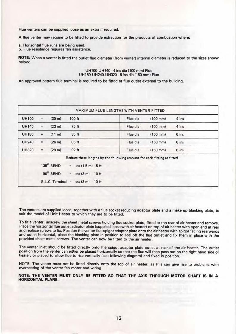
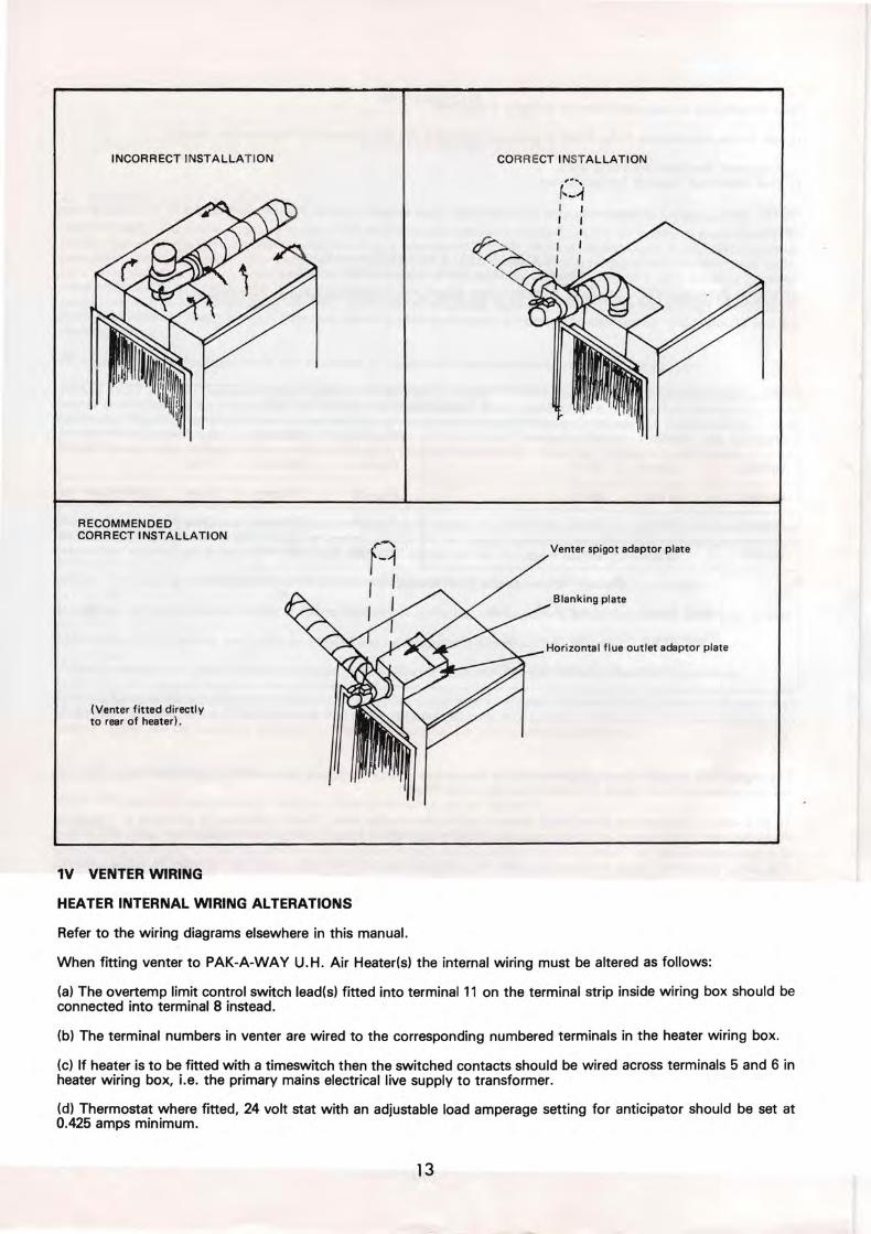
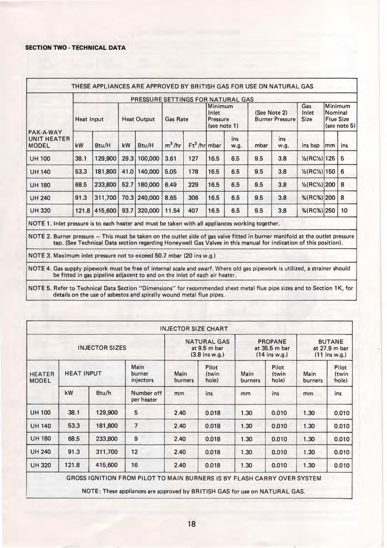
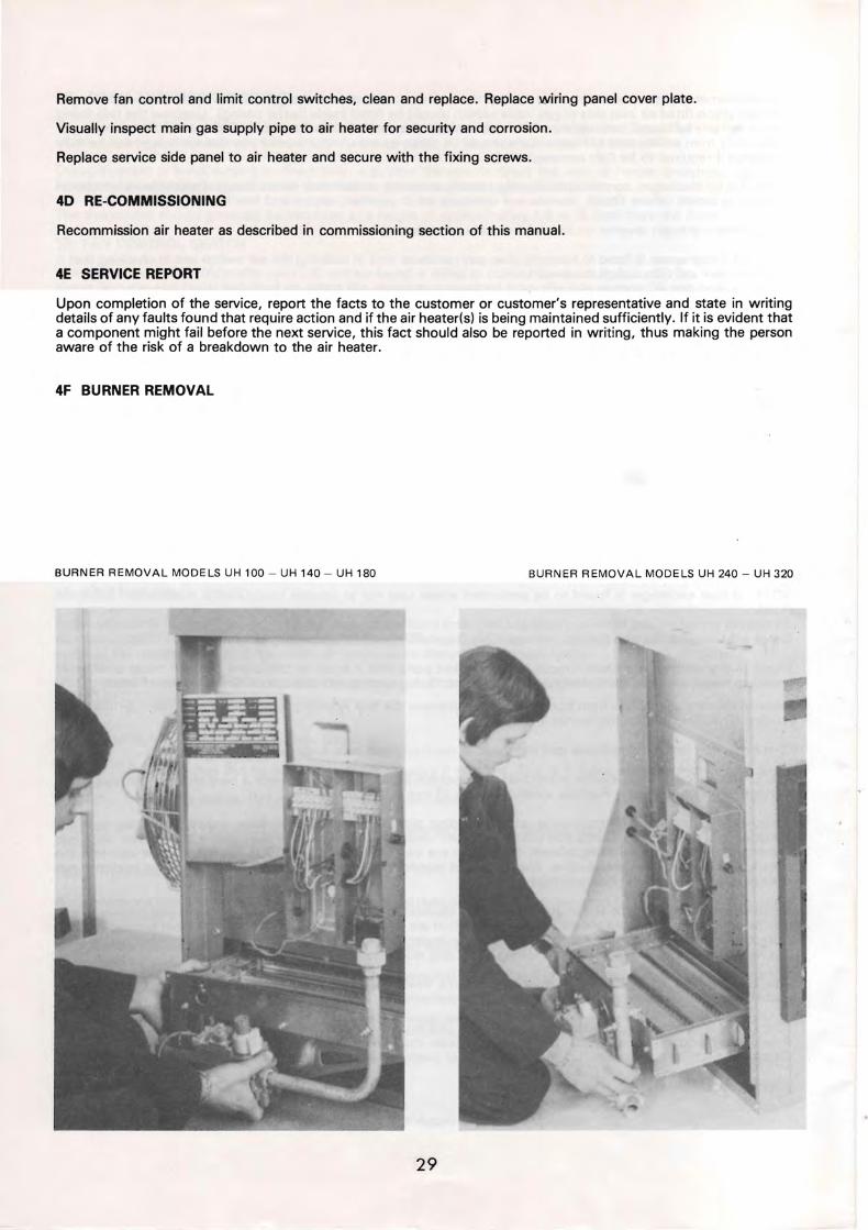
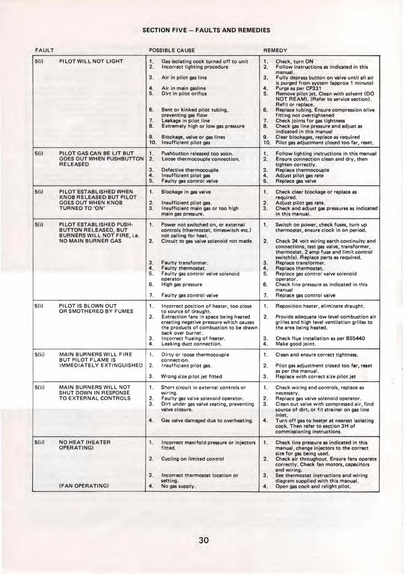
SECTION FIVE - FAULTS AND REMEDIES
FAULT POSSIBLE CAUSE REMEDY
5(i) PILOTWILLNOT LIGHT 1 Gas isolating cock turned off to unit 1 Check turn ON 2 Incorrect lighting procedure 2 Follow instructions as indicated in this
manual 3 Air in pilot gas line 3 Fully depress button on valve until all air
is purged from system (approx 1 minute) 4 Air in main gasline 4 Purge as per CP331 5 Dirt in pilot orifice 5 Remove pilot jet Clean with solvent (DO
NOT REAM) (Refer to service section) Refit or replace
6 Bent or kinked pilot tubing 6 Replace tubing Ensure compression olive preventing gas flow fitting not overtightened
7 Leakage in pilot line 7 Check joints for gas tightness 8 Extremely high or low gas pressure 8 Check gas line pressure and adjust as
indicated in this manual 9 Blockage valve or gas lines 9 Clear blockages replace as required 10 Insufficient pilot gas 10 Pilot gas adjustment closed too far reset
5(i) PI LOT GAS CAN BE LIT BUT 1 Pushbutton released too soon 1 Follow lighting instructions in this manual GOES OUT WHEN PUSHBUTTON 2 Loose thermocouple connection 2 Ensure connection clean and dry then RELEASED tighten correctly
3 Defective thermocouple 3 Replace thermocouple 4 Insufficient pi lot gas 4 Adjust pi lot gas rate 5 Faulty gas control valve 5 Replace gas valve
5(i) PILOT ESTABLISHED WHEN 1 Blockage in gas valve 1 Check clear blockage or replace as KNOB RELEASED BUT PILOT required GOES OUT WH EN KNOB 2 Insufficient pi lot gas 2 Adjust pilot gas rate TURNED TO ON 3 Insufficient main gas or too high 3 Check and adjust gas pressures as indicated
main gas pressure in this manual
5(i) PI LOT ESTABLISHED PUSHmiddot 1 Power not switched on or external 1 Switch on power check fuses turn up BUTTON RELEASED BUT controls (thermostat timeswitch etc thermostat ensure clock in on period BURNERS WILL NOT FIRE ie not calling for heat NO MAIN BURNER GAS 2 Circuit to gas valve solenoid not made 2 Check 24 volt wiring earth continuity and
connections test gas valve transformer thermostat 2 amp fuse and limit control switch(s) Replace parts as required
3 Faulty transformer 3 Replace transformer 4 Faulty thermostat 4 Replace thermostat 5 Faulty gas control valve solenoid 5 Replace gas control valve solenoid
operator operator 6 High gas pressure 6 Check line pressure as indicated in this
manual 7 Faulty gas control valve 7 Replace gas control valve
5(i) PILOT IS BLOWN OUT 1 I ncorrect position of heater too close 1 Reposition heater eliminate draught OR SMOTHERED BY FUMES to source of draught
2 Extraction fans in space being heated 2 Provide adequate low level combustion air creating negative pressure which causes grilles and high level ventilation grilles to the products of combustion to be drawn the area being heated back over burner
3 Incorrect flueing of heater 3 Check flue installation as per BS5440 4 Leaking duct connection 4 Make good jOint
50i) MAIN BURNERS WILL FIRE 1 Dirty or loose thermocouple 1 Clean and ensure correct tightness BUT PILOT FLAME IS connection IMMEDIATELY EXTINGUISHED 2 Insufficient pilot gas 2 Pilot gas adjustment closed too far reset
as per the manual 3 Wrong size pilot jet fitted 3 Replace with correct size pilot jet
50i) MAIN BURNERS WILL NOT 1 Short circuit in external controls or 1 Check wiring and controls replace as SHUT DOWN IN RESPONSE wiring necessary TO EXTERNAL CONTROLS 2 Faulty gas valve solenoid operator 2 Replace gas valve solenoid operator
3 Dirt under gas valve seating preventing 3 Clean out valve with compressed air find valve closure source of dirt or fit strainer on gas line
inlet 4 Gas valve damaged due to overheating 4 Turn off gas to heater at nearest isolating
cock Then refer to section 3H of commissioning instructions
5(iil NO HEAT (HEATER 1 Incorrect manifold pressure or injectors 1 Check line pressure as indicated in this OPERATING) fitted manual change injectors to the correct
size for gas being used 2 Cycling on limited control 2 Check air throughout Ensure fans operate
correctly Check fan motors capacitors and wiring
3 Incorrect thermostat location or 3 See thermostat instructions and wiring setting diagram supplied with this manual
(FAN OPERATING) 4 No gas supply 4 Open gas cock and relight pilot
30
SECTION FIVE - FAULTS AND REMEDIES
FAULT POSSIBLE CAUSE REMEDY
5(iii) COLD AIR IS DELIVERED ON 1 SummerWinter switch (where fitted) 1 Set to automaticwinter setting START UP DURING set in summer position OPERATION OR 2 Faulty fan control switch 2 Replace fan control switch CONTINUOUSL Y WHEN 3 Fan control anticipator incorrectly 3 Rewire as per this manual or diagram BURNER IS OFF wired inside wiring box cover
4 Incorrect gas pressure 4 Adjust gas pressures as per this manual 5 Ambient air temperature low ie cold 5 Increase warm up period on time switch or
start up ensure heater switched on earlier
5(iij) FAN MOTOR WILL NOT RUN 1 Circuit open 1 Check wiring and connections 2 Fan control switch inoperative 2 Replace fan control switch 3 Faulty capacitor 3 Replace capacitor 4 Faulty motor 4 Replace motor
5(iii) FAN MOTOR CUTS IN AND 1 Fan control anticipator improperly 1 Check wiring connection or replace OUT WHILE BURNER IS wired or defective OPERATING 2 Faulty fan control switch 2 Replace fan control switch
3 Low air temperature rise due to low 3 Maintain higher ambient air temperature ambient temperature causing fan switch in space bei ng heated to open and close
4 Insufficient gas supply 4 Check valve and pipework for blockage ensure that gas pipework is correctly sized Adjust gas pressure as per this manual
5(iii) FAN WILL NOT RUN (AND 1 Faulty capacitor 1 Replace fan motor capacitor HUMS UNTIL FLICKED OR RUNS SLOWLY)
31
35
SECTION SIX - SPARES LIST
6A PACK-A-WAY GAS FIRED UNIT HEATERS CONTROL LAYOUT UH 100 -140 -180
31
32-- _ _ _ ~
2
27---~tiLL
29 ---
30 ---~
28
25---__
23-----shy
22 - ---shy
20
21
1 Control Panel (Wiring Box) 2 Control Panel Cover Plate
(NB Wiring Diagram on reverse side) 3 Data Plate 4 Main Terminal Block 240v 5 Burner Terminal Block 24v 6 Fan Control Switch CIW Anticipator 7 Limit Control Switch 8 Transformer 9 Fuse Holder (2 amp fuse fitted)
10 Earth Point 11 Service Union 12 Inlet Pressure Test Point 13 Gas Supply Line 14 Combined Gas Control Valve with
8uilt In Flame Failure Device and Pressure Regulator
15 Control Knob 16 Pressure Regulator (Gas Control Valve)
adjustment screw on top 17 Solenoid Operator 24v 18 Thermocouple Line
36
~---~-32
4
33
5
9
37
7
11
8
25
12
13
24 14
15
19 Pilot Burner Gas Supply Line 20 Burner Manifold 21 Burner Pressure Test Point 22 Pilot Burner 23 Pilot Burner Lighting Hole
with Mica Cover 24 Burner Tray 25 Fixing Screws (Burner Tray) 26 Fan Motor 27 Fan Motor Capacitor 28 Fan Motor Electrical Cable 29 Fan 30 Fan Guard 31 Flue Socket 32 Suspension Eyebolts 33 Downdraught Diverter Vent 34 Base Panel Conduit Knockout 35 Top Panel Electrical Conduit
Entry Holes 36 Top Panel Gas Entry Hole 37 Horizontal Adjustable Louvres
32
SECTION SIX - SPARES LIST
68 PAK-A-WAY GAS FIRED UNIT HEATERS
CONTROL LAYOUT UH 240 - 32035 __________~
31 ___~
32----- - ~
6 33
43
2 ~_--9
10
~-1--37
27 - - --amplol
39 ------IIrr+Wshy
729
11
28 8 25 25 23
12 22
13
20 18
1 Control Panel (Wiring Box) 15 Start Control Knob 31 FI ue Socket 2 Control Panel Cover Plate 16 Stop Control Knob 32 Suspension Eyebolts
(NB Wiring Diagram on reverse side) 17 Solenoid Operator 24v 33 Down Draught Diverter Vent 3 Data Plate 18 Thermocouple Line 34 Base Panel Conduit Knockout 4 Main Terminal Block 240v 19 Pilot Burner Gas Supply Line 35 Top Panel Electrical Conduit 5 Burner Terminal Block 24v 20 Burner Manifold Entry Holes 6 Fan Control Switch CW Anticipator 21 Burner Pressure Test Point 36 Top Panel Gas Entry Hole 7 Limit Control Switch 22 Pilot Burner 37 Horizontal Adjustable Louvres 8 Transformer 23 Pilot Burner Lighting Hole 38 Pressure Regulator (Gas Control 9 Fuse Holder (2 amp Fuse Fitted) with MICA cover Valve) Adjustment screw on
10 Earth Point 24 Burner Tray top 11 Service Union 25 Fixing Screws (Burner Tray) 39 Wiring to Second Limit Control 12 I nlet Pressure Test Point 26 Fan Motor Switch fitted in other side of 13 Gas Supply Li ne 27 Fan Motor Capacitor Heater 14 Combined Gas Control Valve with 28 Fan Motor (Electrical Cables)
built in Flame Fail ure Device and 29 Fan Pressure Regulator 30 Fan Guard
33
36
32
21
24
19 17
f bull RT1
- 1middot I RT2 t--( I
I~ 11
V ELECTRO-MAGNETIC GAS CONTROL VALVE FC FAN CONTROL SWITCH (240V)
L ---210 V N FCA FAN CONTROL SWITCH ANTICIPATOR (24V) LCl OVERTEMP LIMIT CONTROL SWITCH LC2 OVERTEMP LIMIT CONTROL SWITCH (UH240 ti UH320 MODELS
ONLY) Ml FAN MOTOR M2 FAN MOTOR (UH240 IIlt UH320 MODELS ONLY) T TRANSFORMER (240V-24V) 2A FUSE (24V-2AMP)
RTl ROOM THERMOSTAT 240V (OPTIONAL) RT2 ROOM THERMOSTAT 24V (OPTIONAL)
SPECIAL NOTE
1 To connect thermostat remove link between terminals 5 and 6 (240V)or 11 and 12 (24V) as appropriate
2 For timeswitch fused electrical isolator and thermostat connections refer to drawing numbers 0998EUH (24V) and 0999EUH (240V)
3 If thermostat used is 24V and has an adjustable anticipator set to the correct reading by adding appropriate current for the controls listed below
Fan control switch anticipator 01 AMPS
V8600 Gas control valve (UH 1OO-UH 140-UH 180) 02 AMPS
V8800 Gas control valve (UH240-UH320) 02 AMPS
ie 24V Thermostat anticipator setting 03 AMPS
ON NO ACCOUNT SHOULD THE 24 VOLT WIRING OF ONE AIR HEATER BE CONNECTED TO THAT OF ANOTHER HEATER EXCEPT VIA A RELAY HAVING SEPARATE SWITCH CONTACTS OR A PAK-A-WAY CONTROL PANEL IF IN ANY DOUBT CONSULT THE PACKAGE HEATER COMPANY SALES OFFICE ADDRESS AND TELEPHONE NUMBER AS BELOW
I I
- _J
RT1 -- shy
I - I IL_ -- M2i----l
I _ II
(RT2) ~-1
r---~~~~4]~-J-J---r~----------~
- I 0-+--shy1M2 0 +---t-~
_
I I
I
lhI
-~ I
MODELS UH100-UH140-UH180-UH240 amp UH320(PAK-A-WAY)
SINGLE PHASE 240V THE PACKAGE HEATER Co
DATE DRAWN DRG NoFORT ROAD LlTTLEHAMPTON SUSSEX BN17 7EF Tel (0903) 725945 34 2186 W GJ 23301EUH
PT No3062473
fUSED ELE[TRICAL ISOCATfJR [IRCUIT THERMOSTAT ANDOR MANUAL ONOff SWITCH CIRC UI 1
l -------- shy 220240 V AC N---+----e---shy Single Phase Supply E~----t----t__1~--
flee trical Isolator fused A f 5 Amp Rating
00~0 HEATER TERMINAL STRIP
TIHESWJTCH AND THERMOSTAT CIRCUIT
Manual On IOff Thermostat 240V Switch
[]0 00 5 6 []
HEA TER TERMItJAL STRIP
TIMES WITCH THERMOSTA T AND NIGHT SETBACK THERMOSTAT (fROS T STA T) CIRCUIT
Thermostat 240 V 240V
Thermosta~
HEATER TERMINAL STRIP
SutjJULJ~ENJ1L~ TI ON QN_ Lr S W_I_T_CH iI_R_C_Ul_T
OnOff Switch (240 V)
000 45 00 HEATER TERMINA L 5 TRIP
NOTES
1 Items marked ARE NOT supplied by Pak-A-Way
2 ONOFF switching must always be made via the 24V Circuit On no account must the main electrical supply to the air heater be switched OFF except when servicing or in emergency when the gas supply to the heater must be turned off as well (Refer to installation manual for further information)
3 All wiring must be in accordance with the IEE Regulations and any local codes of practice that may apply
00000 567
HEA TER TERMINAL STRIP
SUMMERWINTER SWITCH [JRCUIT
Summer Wir fer Swiici ( 24 () 1)
3
CD 000 4 6 []5
HE ATER TERMINAL S TRI P
On no account should the 24 Volt wiring of one heater be connected to that
of another heater except via a relay having separate switch contacts or a
Pak-A-Way control panel
If in any doubt consult the Package Heater Company Sales Office Address
and telephone number as below
MODELS UH100-UH140-UH180-UH240 amp UH320(PAK-A-WAY) USING 240 VOLT THERMOSTATS (NOTE TO BE READ IN CONJUNCTION WITH DRAWING No 23301 EUH)
THE PACKAGE HEATER Co FORT ROAD LlTTLEHAMPTON SUSSEX DATE DRAWN DRG No BN17 7EF Tel_ (0903) 725945 35 2186 WGJ 0999EUH
FUSED ELECTRICAL ISO[ATOR CIRCUIT THERMOSTAT ANDOR MANUAL ONOFF SWITCH CIRC ul T
L---- shy 220240 V AC ManualN---+--t--- shy Singl e Phase Supply OnOff Switch E---+--+--t_-shy
Thermostat 24V Electrical Isolator
Fused At 5 Amp Rating
0~~0 HEATER TERMINAL STRIP HEATER TERMINAL STRIP
TIMESWITCH AND THERMOSTAT CIRCUIT TIMESWITCH THERHOSTA T AND NIGHT SETBACK THERMOSTAT (FROST STA T) CIRCUIT
Thermos tat
~0~ HEATER TERMINAL STRIPS
SUMMER VENTILATION ONLY SWTC H CfRCUIT
OnOff Switch (240 V)
000 45 00 HEATER TERMINAL STRIP
NOTES
1 Items marked ARE NOT supplied by Fak-A-Way
2 ONOFF switching must always be made via the 24V Circuit On no account must the main electrical supply to the air heater be switched OFF except when servicing or in emergency when the gas supply to the heater must be turned off as well (Refer to installation manual for further information)
3 All wiring must be in accordance with the IEE Regulations and any local codes of practice that may apply
Thermos tat
000050 7 LJLJ~1J HEATER TERHINAL STRIPS
S U11ER WIN TE R SWITCH CIRCUIT
(0000 456 0 HE ATER TERHINAL STRI P
WARNING - TIME SWITCHES
Timeswitches must be fitted with separate motor connections when switch
contacts are being used to control the 24V circuit
On no account should the 24 Volt wiring of one heater be connected to that
of another heater except via a relay having separate switch contacts or a
Pak-A-Way control panel
If in any doubt consult the Package Heater Company Sales Office Address
and telephone number as below
MODELS UH1 00-UH140-UH180-UH240 amp UH320(PAK-A-WAV) USING 24 VOLT THERMOSTATS (NOTE TO BE READ IN CONJUNCTION WITH DRAWING No 23301 EUH)
THE PACKAGE HEATER Co FORT ROAD LlTTLEHAMPTON SUSSEX DATE DRAWN DRG No BN177EF Tel (0903) 725945 36 WGJ2186 0998EUH
-~LJ J ( H 2 -J -t----+ shy_ ~-4----+-------J
1- - -- shy
I ILU tL ~ - - -----iro--t----_ I --- shy
L N240 V
-1
~ 240X __
Er--- -
I
- -1
ii RT2 I
I I I I I I I
I I I L_J I
~1
I
AI
I I I
~4 V J J - --= ~
------~
HEATER WIRING MODIFICATION The lead(s) from the overtemp limit control switch(es) wired internally as standard to terminal 11 must be disconnected and rewired into terminal 8 as shown on this wiring diagram The terminals on the venter and heater are then connected directly between each corresponding number
On no account should the 24 Volt wiring of one heater be connected to that of another heater except via a relay having separate switch contacts or a Pak-A-Way control panel
If in any doubt consult the Package Heater Company Sales Office Address and telephone number as below
For timeswitch electrical isolator thermostat and summerIwinter switch connections refer to drawing numbers 0998EUH (24V) and 0999EUH (240V)
V ELECTRO-MAGNETIC GAS CONTROL VALVE FC FAN CONTROL SWITCH (240V) FCA FAN CONTROL SWITCH ANTICIPATOR (24V) LC1 OVERTEMP LIMIT CONTROL SWITCH LC2 OVERTEMP LIMIT CONTROL SWITCH (UH240 amp UH320 MODELS
ONLY) M1 FAN MOTOR M2 FAN MOTOR (UH240 amp UH320 MODELS ONLY) T TRANSFORMER (240V-24V) 2A FUSE (24V-2AMP) VM VENTER FAN MOTOR VR VENTER RELAY (24V) VRS VENTER RELAY SWITCH (240V) AS AIR SAIL SWITCH (24V)
RT1 ROOM THERMOSTAT 240V (OPTIONAL) RT2 ROOM THERMOSTAT 24V (OPTIONAL)
SPECIAL NOTE
1 To connect thermostat remove link between terminals 5 and 6 (240V) or 11 and 12 (24V) as appropriate
2 If thermostat used is 24V and has an adjustable anticipator set to the correct reading by adding appropriate current for the controls listed below
Fan control switch anticipator 01 AMPS
V8600 Gas Valve (UH100-UH140-UH180) 02 AMPS
V8800 Gas Valve (UH240-UH320) 02 AMPS
Flue venter relay 0125 AMPS
ie 24V Thermostat anticipator setting 0425 AMPS minimum with venter fitted
3 All wiring must be in accordance with the IEE regulations and any local codes of practice that may apply
MODELS UH100-UH140-UH180-UH240 amp UH320( PAK-A-WAY ) USING A FLUE VENTER
SINGLE PHASE 240VTHE PACKAGE HEATER CO FORT ROAD LlTTLEHAMPTON SUSSEX DATE DRAWN DRG No BN177EF Tel (0903) 725945 37 2186 WGJ 23302EUH
JANUARY 1986 ( PAK-A-WAY)
COVERS PAK-A-WAY MODELS UHIOO-UH140-UH180-UH240-UH320
USERS INSTRUCTIONS
HANG THIS CARD NEAR YOUR HEATER
WARNING This appliance must be earthed
IMPORTANT In the interest of safety and user satisfaction these instructions should be read and fu lly understood To operate safely and efficiently t his appliance must be serviced regularly by a competent person Seek advice of your installer or local Gas Region Service Centre who will arrange for a service or cont ract service Difficu lties in this regard should be addressed in writing to the manufactu rers office Failu re to accept this advice could affect applicable warrantees
GENERAL Pak-A-Way UH Model Heaters are designed and manufactured to provide many years of rel iable service PA CKAGE HEATER have built into your air heater safety quality reliability and good performance Every appliance is factory inspected and tested and comprehenshysive instructions have been provided to the installer in an endeavour to ensure that your heater is correctly fitted and commissioned so that it will do the job for which it is designed
HOW THE AIR HEATER WORKS A gas burner is controlled on and off by a thermostat andor a t ime switch control which can be regulated by t he user A permanent pilot burner is employed to light the gas burner and is used to maintain a safety sensor for automatic shut down in the event of flame failure thus preventing unburnt gas escaping to cause a hazard The burner heats a sealed steel Heat Exchanger from which products of combustion are exhausted via flue system to t he outdoor atmosphere When the temperature in the air heater casing reaches a prescribed degree thermally activated switches switch on the air circulation fan and in the event of overheating shut down the burner thus ensuring the safe operat ion The air circulation fan w ill not start at the same t ime as the burner and will continue to run when the burner has shut down This ensures that cold air w ill not be blown from the heater and that the heater is cooled adequately at the end of the heating cycle
NOTE Left and right definitions referred to in these instructions are assuming that discharged air will blow onto the face of the viewer
LIGHTING amp OPERATING INSTRUCTIONS
BEFORE STARTING THE AIR HEATER Ensure that all warm air louvres and ducting grilles if fitted are open Locate the pilot burner and gas cont rol valve which are situated behind the bottom hinged lower access panel on the left hand side of the air heater The pilot burner is directly behind the lighting port window (figs 1 or 2)
WARNING IF THE PILOT LIGHT IS EXTINGUISHED EITHER INTENTIONALLY OR UNINTENTIONALLY NO ATTEMPT SHOULD BE MADE TO RELIGHT THE GAS UNTIL AT LEAST 3 MINUTES HAVE ELAPSED
TO START THE AIR HEATER
1 Ensure that the main gas supply to the air heater is ON
2 Switch OFF the electricity supply to the air heater
3 Set room thermostat to OFF or its LOWEST sett ing If fi tted ensure t ime switch is set to an ON period
4 Press in fully the start button on the gas control va lve (models UH100 UH 140 and UH180) or t he white start button (models UH240 and UH320) and at the same t ime apply a lighted match or taper to the pilot burner
5 Once the pilot is alight continue to keep the button fully depressed for at least 20 seconds before releasing If the pilot f lame goes out turn the start button (models UH100 UH140 UH 180) clockwise about a quarter turn wait 3 minutes then repeat from step (4) For models UH240 UH320 push in the red button wait 3 minutes t hen repeat from step 4
6 With the pilot flame established replace the pilot port w indow and burner compartment access panel
7 Switch ON the electricity supply to the air heater
8 Adjust room thermostat to desired temperature or switch on control switch as applicable and main burner wi ll light
TO TURN OFF THE AIR HEATER
For short periods
Adjust the room thermostat to lowest setting or OFF or if fitted switch OFF the manual control switch The air heater will remain ready for use immediately these controls are re-adjusted
To turn OFF completely for a prolonged period
a Switch OFF manual cont rol sw itch and turn room thermostat to OFF or LOWEST setting
b Turn the start button on the gas control valve for models UH100 UH140 UH180 clockwise about a quarter turn For models UH240 amp UH320 push in the red stop button on the gas control This shuts down the gas supply to the main and pilot burners
c Wait 5 minutes and then switch OFF t he main electricity supply to the air heater and turn OFF the gas supply using the externally located gas tap
AIR CIRCULATION Some Pak-A-W ay Unit A ir Heaters are connected to an air fan over ride switch This enables forced air to be used for circulation purposes when the heater is not used for heating purposes ie Summer months
a Switch ON mains electricity to the air heater
b Switch ON the manual over-ride switch
c Where fan over-ride switch is not f itted turn off gas supply turn up setting on room thermostat Fan w ill start after approx one minute During the low ambient temperature periods (i e cold morning sta rt up) the air circulation fan may run and stop at irregu lar intervals This is due to the cold air being drawn through the air heater cooling the thermostatic fan switch to below its normal constant running temperature This is normal and will be automatically corrected as the ambient temperature rises
Figl Lighting Instructions UH 100 - UH140 - UH 180
MAINTENANCE AND SERVICING Maintenance and service must only be carried out by competent persons Periods between service are dependant upon the local environment where the air heater is installed Regular inspection is recommended initially to ascertain routine intervals and where local environmental circumstances change i e different processes being carried out in a factory the service interval should be reconsidered Ask your installer service undertaking or the manufacturer about inspection and service intervals
TH E AIR HEATER SHOULD BE SERVICED AT LEAST ONCE EVERY HEATING SEASON
PAK-A-WAY UH AIR HEATERS ARE APPROVED BY BRITISH GAS FOR USE ON NATURAL GAS
Fig 2 Light ing Instructions UH240 - UH320
Heater Model UH f
THE PACKAGE HEATER CO Fort Road Littlehampton Sussex BN17 7 EF
Tel (0903) 725945
SERVICE RECORD
INSTALLED BY
Serial Number ~ ~------~
REMARKS Use of this type of heater in corrosive or inflammable atmosphere is not recommended Warranty is void if heater is operated in the presence of chlorinated vapours
MODELS amp DATA Subject to modification without prior notice
DATE
COMMISSIONED
- Pakaway UH Series 1pdf
- Pakaway UH Series 2
- Pakaway UH Series 3
-
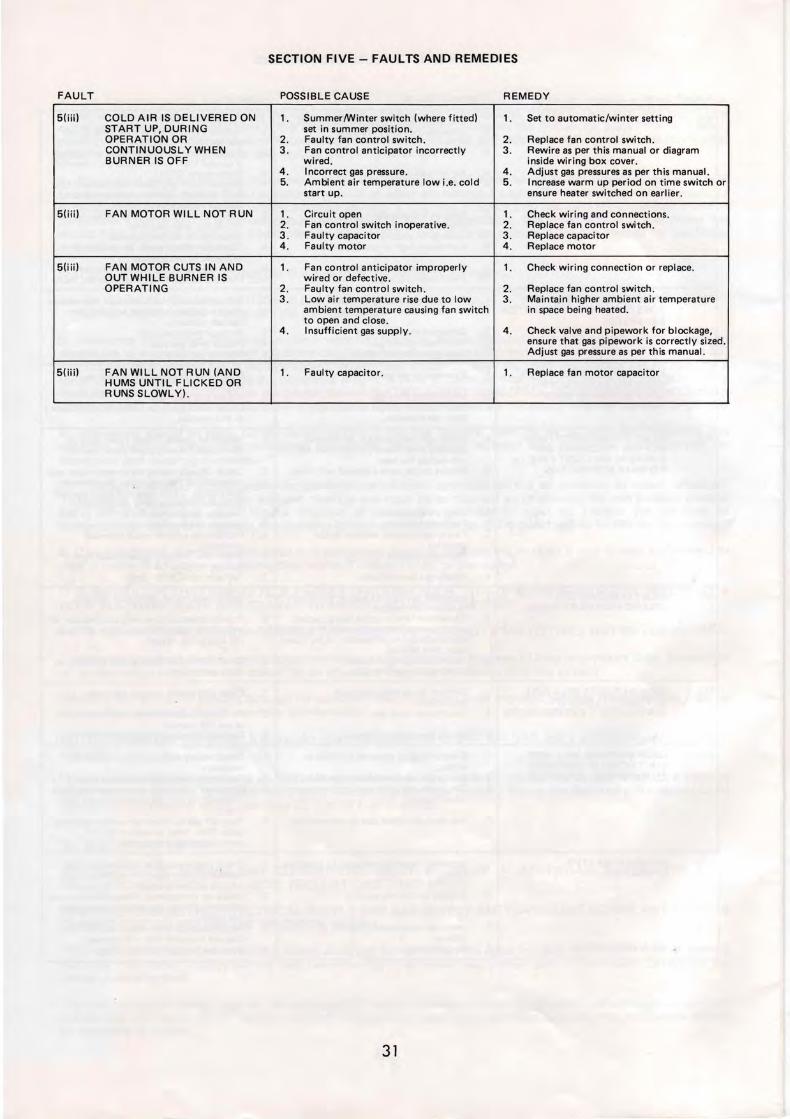
SECTION FIVE - FAULTS AND REMEDIES
FAULT POSSIBLE CAUSE REMEDY
5(iii) COLD AIR IS DELIVERED ON 1 SummerWinter switch (where fitted) 1 Set to automaticwinter setting START UP DURING set in summer position OPERATION OR 2 Faulty fan control switch 2 Replace fan control switch CONTINUOUSL Y WHEN 3 Fan control anticipator incorrectly 3 Rewire as per this manual or diagram BURNER IS OFF wired inside wiring box cover
4 Incorrect gas pressure 4 Adjust gas pressures as per this manual 5 Ambient air temperature low ie cold 5 Increase warm up period on time switch or
start up ensure heater switched on earlier
5(iij) FAN MOTOR WILL NOT RUN 1 Circuit open 1 Check wiring and connections 2 Fan control switch inoperative 2 Replace fan control switch 3 Faulty capacitor 3 Replace capacitor 4 Faulty motor 4 Replace motor
5(iii) FAN MOTOR CUTS IN AND 1 Fan control anticipator improperly 1 Check wiring connection or replace OUT WHILE BURNER IS wired or defective OPERATING 2 Faulty fan control switch 2 Replace fan control switch
3 Low air temperature rise due to low 3 Maintain higher ambient air temperature ambient temperature causing fan switch in space bei ng heated to open and close
4 Insufficient gas supply 4 Check valve and pipework for blockage ensure that gas pipework is correctly sized Adjust gas pressure as per this manual
5(iii) FAN WILL NOT RUN (AND 1 Faulty capacitor 1 Replace fan motor capacitor HUMS UNTIL FLICKED OR RUNS SLOWLY)
31
35
SECTION SIX - SPARES LIST
6A PACK-A-WAY GAS FIRED UNIT HEATERS CONTROL LAYOUT UH 100 -140 -180
31
32-- _ _ _ ~
2
27---~tiLL
29 ---
30 ---~
28
25---__
23-----shy
22 - ---shy
20
21
1 Control Panel (Wiring Box) 2 Control Panel Cover Plate
(NB Wiring Diagram on reverse side) 3 Data Plate 4 Main Terminal Block 240v 5 Burner Terminal Block 24v 6 Fan Control Switch CIW Anticipator 7 Limit Control Switch 8 Transformer 9 Fuse Holder (2 amp fuse fitted)
10 Earth Point 11 Service Union 12 Inlet Pressure Test Point 13 Gas Supply Line 14 Combined Gas Control Valve with
8uilt In Flame Failure Device and Pressure Regulator
15 Control Knob 16 Pressure Regulator (Gas Control Valve)
adjustment screw on top 17 Solenoid Operator 24v 18 Thermocouple Line
36
~---~-32
4
33
5
9
37
7
11
8
25
12
13
24 14
15
19 Pilot Burner Gas Supply Line 20 Burner Manifold 21 Burner Pressure Test Point 22 Pilot Burner 23 Pilot Burner Lighting Hole
with Mica Cover 24 Burner Tray 25 Fixing Screws (Burner Tray) 26 Fan Motor 27 Fan Motor Capacitor 28 Fan Motor Electrical Cable 29 Fan 30 Fan Guard 31 Flue Socket 32 Suspension Eyebolts 33 Downdraught Diverter Vent 34 Base Panel Conduit Knockout 35 Top Panel Electrical Conduit
Entry Holes 36 Top Panel Gas Entry Hole 37 Horizontal Adjustable Louvres
32
SECTION SIX - SPARES LIST
68 PAK-A-WAY GAS FIRED UNIT HEATERS
CONTROL LAYOUT UH 240 - 32035 __________~
31 ___~
32----- - ~
6 33
43
2 ~_--9
10
~-1--37
27 - - --amplol
39 ------IIrr+Wshy
729
11
28 8 25 25 23
12 22
13
20 18
1 Control Panel (Wiring Box) 15 Start Control Knob 31 FI ue Socket 2 Control Panel Cover Plate 16 Stop Control Knob 32 Suspension Eyebolts
(NB Wiring Diagram on reverse side) 17 Solenoid Operator 24v 33 Down Draught Diverter Vent 3 Data Plate 18 Thermocouple Line 34 Base Panel Conduit Knockout 4 Main Terminal Block 240v 19 Pilot Burner Gas Supply Line 35 Top Panel Electrical Conduit 5 Burner Terminal Block 24v 20 Burner Manifold Entry Holes 6 Fan Control Switch CW Anticipator 21 Burner Pressure Test Point 36 Top Panel Gas Entry Hole 7 Limit Control Switch 22 Pilot Burner 37 Horizontal Adjustable Louvres 8 Transformer 23 Pilot Burner Lighting Hole 38 Pressure Regulator (Gas Control 9 Fuse Holder (2 amp Fuse Fitted) with MICA cover Valve) Adjustment screw on
10 Earth Point 24 Burner Tray top 11 Service Union 25 Fixing Screws (Burner Tray) 39 Wiring to Second Limit Control 12 I nlet Pressure Test Point 26 Fan Motor Switch fitted in other side of 13 Gas Supply Li ne 27 Fan Motor Capacitor Heater 14 Combined Gas Control Valve with 28 Fan Motor (Electrical Cables)
built in Flame Fail ure Device and 29 Fan Pressure Regulator 30 Fan Guard
33
36
32
21
24
19 17
f bull RT1
- 1middot I RT2 t--( I
I~ 11
V ELECTRO-MAGNETIC GAS CONTROL VALVE FC FAN CONTROL SWITCH (240V)
L ---210 V N FCA FAN CONTROL SWITCH ANTICIPATOR (24V) LCl OVERTEMP LIMIT CONTROL SWITCH LC2 OVERTEMP LIMIT CONTROL SWITCH (UH240 ti UH320 MODELS
ONLY) Ml FAN MOTOR M2 FAN MOTOR (UH240 IIlt UH320 MODELS ONLY) T TRANSFORMER (240V-24V) 2A FUSE (24V-2AMP)
RTl ROOM THERMOSTAT 240V (OPTIONAL) RT2 ROOM THERMOSTAT 24V (OPTIONAL)
SPECIAL NOTE
1 To connect thermostat remove link between terminals 5 and 6 (240V)or 11 and 12 (24V) as appropriate
2 For timeswitch fused electrical isolator and thermostat connections refer to drawing numbers 0998EUH (24V) and 0999EUH (240V)
3 If thermostat used is 24V and has an adjustable anticipator set to the correct reading by adding appropriate current for the controls listed below
Fan control switch anticipator 01 AMPS
V8600 Gas control valve (UH 1OO-UH 140-UH 180) 02 AMPS
V8800 Gas control valve (UH240-UH320) 02 AMPS
ie 24V Thermostat anticipator setting 03 AMPS
ON NO ACCOUNT SHOULD THE 24 VOLT WIRING OF ONE AIR HEATER BE CONNECTED TO THAT OF ANOTHER HEATER EXCEPT VIA A RELAY HAVING SEPARATE SWITCH CONTACTS OR A PAK-A-WAY CONTROL PANEL IF IN ANY DOUBT CONSULT THE PACKAGE HEATER COMPANY SALES OFFICE ADDRESS AND TELEPHONE NUMBER AS BELOW
I I
- _J
RT1 -- shy
I - I IL_ -- M2i----l
I _ II
(RT2) ~-1
r---~~~~4]~-J-J---r~----------~
- I 0-+--shy1M2 0 +---t-~
_
I I
I
lhI
-~ I
MODELS UH100-UH140-UH180-UH240 amp UH320(PAK-A-WAY)
SINGLE PHASE 240V THE PACKAGE HEATER Co
DATE DRAWN DRG NoFORT ROAD LlTTLEHAMPTON SUSSEX BN17 7EF Tel (0903) 725945 34 2186 W GJ 23301EUH
PT No3062473
fUSED ELE[TRICAL ISOCATfJR [IRCUIT THERMOSTAT ANDOR MANUAL ONOff SWITCH CIRC UI 1
l -------- shy 220240 V AC N---+----e---shy Single Phase Supply E~----t----t__1~--
flee trical Isolator fused A f 5 Amp Rating
00~0 HEATER TERMINAL STRIP
TIHESWJTCH AND THERMOSTAT CIRCUIT
Manual On IOff Thermostat 240V Switch
[]0 00 5 6 []
HEA TER TERMItJAL STRIP
TIMES WITCH THERMOSTA T AND NIGHT SETBACK THERMOSTAT (fROS T STA T) CIRCUIT
Thermostat 240 V 240V
Thermosta~
HEATER TERMINAL STRIP
SutjJULJ~ENJ1L~ TI ON QN_ Lr S W_I_T_CH iI_R_C_Ul_T
OnOff Switch (240 V)
000 45 00 HEATER TERMINA L 5 TRIP
NOTES
1 Items marked ARE NOT supplied by Pak-A-Way
2 ONOFF switching must always be made via the 24V Circuit On no account must the main electrical supply to the air heater be switched OFF except when servicing or in emergency when the gas supply to the heater must be turned off as well (Refer to installation manual for further information)
3 All wiring must be in accordance with the IEE Regulations and any local codes of practice that may apply
00000 567
HEA TER TERMINAL STRIP
SUMMERWINTER SWITCH [JRCUIT
Summer Wir fer Swiici ( 24 () 1)
3
CD 000 4 6 []5
HE ATER TERMINAL S TRI P
On no account should the 24 Volt wiring of one heater be connected to that
of another heater except via a relay having separate switch contacts or a
Pak-A-Way control panel
If in any doubt consult the Package Heater Company Sales Office Address
and telephone number as below
MODELS UH100-UH140-UH180-UH240 amp UH320(PAK-A-WAY) USING 240 VOLT THERMOSTATS (NOTE TO BE READ IN CONJUNCTION WITH DRAWING No 23301 EUH)
THE PACKAGE HEATER Co FORT ROAD LlTTLEHAMPTON SUSSEX DATE DRAWN DRG No BN17 7EF Tel_ (0903) 725945 35 2186 WGJ 0999EUH
FUSED ELECTRICAL ISO[ATOR CIRCUIT THERMOSTAT ANDOR MANUAL ONOFF SWITCH CIRC ul T
L---- shy 220240 V AC ManualN---+--t--- shy Singl e Phase Supply OnOff Switch E---+--+--t_-shy
Thermostat 24V Electrical Isolator
Fused At 5 Amp Rating
0~~0 HEATER TERMINAL STRIP HEATER TERMINAL STRIP
TIMESWITCH AND THERMOSTAT CIRCUIT TIMESWITCH THERHOSTA T AND NIGHT SETBACK THERMOSTAT (FROST STA T) CIRCUIT
Thermos tat
~0~ HEATER TERMINAL STRIPS
SUMMER VENTILATION ONLY SWTC H CfRCUIT
OnOff Switch (240 V)
000 45 00 HEATER TERMINAL STRIP
NOTES
1 Items marked ARE NOT supplied by Fak-A-Way
2 ONOFF switching must always be made via the 24V Circuit On no account must the main electrical supply to the air heater be switched OFF except when servicing or in emergency when the gas supply to the heater must be turned off as well (Refer to installation manual for further information)
3 All wiring must be in accordance with the IEE Regulations and any local codes of practice that may apply
Thermos tat
000050 7 LJLJ~1J HEATER TERHINAL STRIPS
S U11ER WIN TE R SWITCH CIRCUIT
(0000 456 0 HE ATER TERHINAL STRI P
WARNING - TIME SWITCHES
Timeswitches must be fitted with separate motor connections when switch
contacts are being used to control the 24V circuit
On no account should the 24 Volt wiring of one heater be connected to that
of another heater except via a relay having separate switch contacts or a
Pak-A-Way control panel
If in any doubt consult the Package Heater Company Sales Office Address
and telephone number as below
MODELS UH1 00-UH140-UH180-UH240 amp UH320(PAK-A-WAV) USING 24 VOLT THERMOSTATS (NOTE TO BE READ IN CONJUNCTION WITH DRAWING No 23301 EUH)
THE PACKAGE HEATER Co FORT ROAD LlTTLEHAMPTON SUSSEX DATE DRAWN DRG No BN177EF Tel (0903) 725945 36 WGJ2186 0998EUH
-~LJ J ( H 2 -J -t----+ shy_ ~-4----+-------J
1- - -- shy
I ILU tL ~ - - -----iro--t----_ I --- shy
L N240 V
-1
~ 240X __
Er--- -
I
- -1
ii RT2 I
I I I I I I I
I I I L_J I
~1
I
AI
I I I
~4 V J J - --= ~
------~
HEATER WIRING MODIFICATION The lead(s) from the overtemp limit control switch(es) wired internally as standard to terminal 11 must be disconnected and rewired into terminal 8 as shown on this wiring diagram The terminals on the venter and heater are then connected directly between each corresponding number
On no account should the 24 Volt wiring of one heater be connected to that of another heater except via a relay having separate switch contacts or a Pak-A-Way control panel
If in any doubt consult the Package Heater Company Sales Office Address and telephone number as below
For timeswitch electrical isolator thermostat and summerIwinter switch connections refer to drawing numbers 0998EUH (24V) and 0999EUH (240V)
V ELECTRO-MAGNETIC GAS CONTROL VALVE FC FAN CONTROL SWITCH (240V) FCA FAN CONTROL SWITCH ANTICIPATOR (24V) LC1 OVERTEMP LIMIT CONTROL SWITCH LC2 OVERTEMP LIMIT CONTROL SWITCH (UH240 amp UH320 MODELS
ONLY) M1 FAN MOTOR M2 FAN MOTOR (UH240 amp UH320 MODELS ONLY) T TRANSFORMER (240V-24V) 2A FUSE (24V-2AMP) VM VENTER FAN MOTOR VR VENTER RELAY (24V) VRS VENTER RELAY SWITCH (240V) AS AIR SAIL SWITCH (24V)
RT1 ROOM THERMOSTAT 240V (OPTIONAL) RT2 ROOM THERMOSTAT 24V (OPTIONAL)
SPECIAL NOTE
1 To connect thermostat remove link between terminals 5 and 6 (240V) or 11 and 12 (24V) as appropriate
2 If thermostat used is 24V and has an adjustable anticipator set to the correct reading by adding appropriate current for the controls listed below
Fan control switch anticipator 01 AMPS
V8600 Gas Valve (UH100-UH140-UH180) 02 AMPS
V8800 Gas Valve (UH240-UH320) 02 AMPS
Flue venter relay 0125 AMPS
ie 24V Thermostat anticipator setting 0425 AMPS minimum with venter fitted
3 All wiring must be in accordance with the IEE regulations and any local codes of practice that may apply
MODELS UH100-UH140-UH180-UH240 amp UH320( PAK-A-WAY ) USING A FLUE VENTER
SINGLE PHASE 240VTHE PACKAGE HEATER CO FORT ROAD LlTTLEHAMPTON SUSSEX DATE DRAWN DRG No BN177EF Tel (0903) 725945 37 2186 WGJ 23302EUH
JANUARY 1986 ( PAK-A-WAY)
COVERS PAK-A-WAY MODELS UHIOO-UH140-UH180-UH240-UH320
USERS INSTRUCTIONS
HANG THIS CARD NEAR YOUR HEATER
WARNING This appliance must be earthed
IMPORTANT In the interest of safety and user satisfaction these instructions should be read and fu lly understood To operate safely and efficiently t his appliance must be serviced regularly by a competent person Seek advice of your installer or local Gas Region Service Centre who will arrange for a service or cont ract service Difficu lties in this regard should be addressed in writing to the manufactu rers office Failu re to accept this advice could affect applicable warrantees
GENERAL Pak-A-Way UH Model Heaters are designed and manufactured to provide many years of rel iable service PA CKAGE HEATER have built into your air heater safety quality reliability and good performance Every appliance is factory inspected and tested and comprehenshysive instructions have been provided to the installer in an endeavour to ensure that your heater is correctly fitted and commissioned so that it will do the job for which it is designed
HOW THE AIR HEATER WORKS A gas burner is controlled on and off by a thermostat andor a t ime switch control which can be regulated by t he user A permanent pilot burner is employed to light the gas burner and is used to maintain a safety sensor for automatic shut down in the event of flame failure thus preventing unburnt gas escaping to cause a hazard The burner heats a sealed steel Heat Exchanger from which products of combustion are exhausted via flue system to t he outdoor atmosphere When the temperature in the air heater casing reaches a prescribed degree thermally activated switches switch on the air circulation fan and in the event of overheating shut down the burner thus ensuring the safe operat ion The air circulation fan w ill not start at the same t ime as the burner and will continue to run when the burner has shut down This ensures that cold air w ill not be blown from the heater and that the heater is cooled adequately at the end of the heating cycle
NOTE Left and right definitions referred to in these instructions are assuming that discharged air will blow onto the face of the viewer
LIGHTING amp OPERATING INSTRUCTIONS
BEFORE STARTING THE AIR HEATER Ensure that all warm air louvres and ducting grilles if fitted are open Locate the pilot burner and gas cont rol valve which are situated behind the bottom hinged lower access panel on the left hand side of the air heater The pilot burner is directly behind the lighting port window (figs 1 or 2)
WARNING IF THE PILOT LIGHT IS EXTINGUISHED EITHER INTENTIONALLY OR UNINTENTIONALLY NO ATTEMPT SHOULD BE MADE TO RELIGHT THE GAS UNTIL AT LEAST 3 MINUTES HAVE ELAPSED
TO START THE AIR HEATER
1 Ensure that the main gas supply to the air heater is ON
2 Switch OFF the electricity supply to the air heater
3 Set room thermostat to OFF or its LOWEST sett ing If fi tted ensure t ime switch is set to an ON period
4 Press in fully the start button on the gas control va lve (models UH100 UH 140 and UH180) or t he white start button (models UH240 and UH320) and at the same t ime apply a lighted match or taper to the pilot burner
5 Once the pilot is alight continue to keep the button fully depressed for at least 20 seconds before releasing If the pilot f lame goes out turn the start button (models UH100 UH140 UH 180) clockwise about a quarter turn wait 3 minutes then repeat from step (4) For models UH240 UH320 push in the red button wait 3 minutes t hen repeat from step 4
6 With the pilot flame established replace the pilot port w indow and burner compartment access panel
7 Switch ON the electricity supply to the air heater
8 Adjust room thermostat to desired temperature or switch on control switch as applicable and main burner wi ll light
TO TURN OFF THE AIR HEATER
For short periods
Adjust the room thermostat to lowest setting or OFF or if fitted switch OFF the manual control switch The air heater will remain ready for use immediately these controls are re-adjusted
To turn OFF completely for a prolonged period
a Switch OFF manual cont rol sw itch and turn room thermostat to OFF or LOWEST setting
b Turn the start button on the gas control valve for models UH100 UH140 UH180 clockwise about a quarter turn For models UH240 amp UH320 push in the red stop button on the gas control This shuts down the gas supply to the main and pilot burners
c Wait 5 minutes and then switch OFF t he main electricity supply to the air heater and turn OFF the gas supply using the externally located gas tap
AIR CIRCULATION Some Pak-A-W ay Unit A ir Heaters are connected to an air fan over ride switch This enables forced air to be used for circulation purposes when the heater is not used for heating purposes ie Summer months
a Switch ON mains electricity to the air heater
b Switch ON the manual over-ride switch
c Where fan over-ride switch is not f itted turn off gas supply turn up setting on room thermostat Fan w ill start after approx one minute During the low ambient temperature periods (i e cold morning sta rt up) the air circulation fan may run and stop at irregu lar intervals This is due to the cold air being drawn through the air heater cooling the thermostatic fan switch to below its normal constant running temperature This is normal and will be automatically corrected as the ambient temperature rises
Figl Lighting Instructions UH 100 - UH140 - UH 180
MAINTENANCE AND SERVICING Maintenance and service must only be carried out by competent persons Periods between service are dependant upon the local environment where the air heater is installed Regular inspection is recommended initially to ascertain routine intervals and where local environmental circumstances change i e different processes being carried out in a factory the service interval should be reconsidered Ask your installer service undertaking or the manufacturer about inspection and service intervals
TH E AIR HEATER SHOULD BE SERVICED AT LEAST ONCE EVERY HEATING SEASON
PAK-A-WAY UH AIR HEATERS ARE APPROVED BY BRITISH GAS FOR USE ON NATURAL GAS
Fig 2 Light ing Instructions UH240 - UH320
Heater Model UH f
THE PACKAGE HEATER CO Fort Road Littlehampton Sussex BN17 7 EF
Tel (0903) 725945
SERVICE RECORD
INSTALLED BY
Serial Number ~ ~------~
REMARKS Use of this type of heater in corrosive or inflammable atmosphere is not recommended Warranty is void if heater is operated in the presence of chlorinated vapours
MODELS amp DATA Subject to modification without prior notice
DATE
COMMISSIONED
- Pakaway UH Series 1pdf
- Pakaway UH Series 2
- Pakaway UH Series 3
-
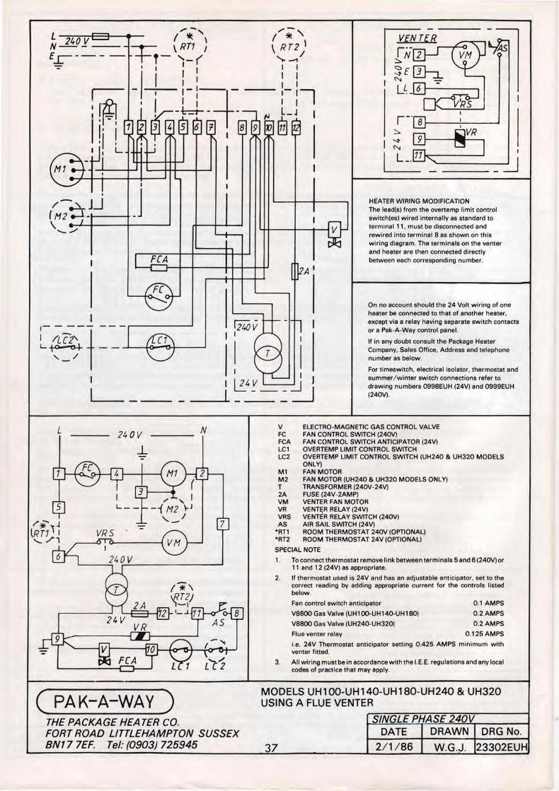