gasification characteristics of rapid thermal pyrolyzer residue in a fluidized bed...
TRANSCRIPT

Gasification Characteristics of Rapid Thermal Pyrolyzer Residue in aFluidized Bed ReactorMyung Won Seo,†,‡ Young Tae Guahk,† Nam Sun Rho,† Sang Jun Yoon,†,‡ Ho Won Ra,†
Geon Hoe Koo,† Yong Ku Kim,† Jae Ho Kim,†,‡ Jae Goo Lee,*,†,‡ and Sang Done Kim§
†Clean Fuel Laboratory, Korea Institute of Energy Research (KIER), 152 Gajeong-ro, Yuseong-gu, Daejeon, 305-343, Republic ofKorea‡Department of New Energy Technology, University of Science and Technology (UST), 217 Gajeong-ro, Yuseong-gu, Daejeon,305-350, Republic of Korea§Department of Chemical and Biomolecular Engineering, Korea Advanced Institute of Science and Technology (KAIST), 291Daehak-ro, Yuseong-gu, Daejeon 305-701, Republic of Korea
ABSTRACT: A novel process has been developed at KIER (Korea Institute of Energy Research) for upgrading extra-heavy oilfractions. This process uses a rapid thermal pyrolysis (RTP) of extra-heavy oil with a gasifier/combustor of RTP residue toproduce syngas as well as to supply heat to the pyrolyzer. Unreacted carbon in RTP residues from the pyrolyzer are used as afeedstock to the gasifier/combustor. The RTP residue is mostly sand with 1 wt % of petroleum coke.The possibility that productgas from the gasifier/combustor can supply heat to the pyrolyzer is examined. A continuous fluidized bed reactor with themaximum capacity of 10 kg/h (0.05 m I.D. × 1.2 m high) was designed and constructed for RTP residue gasification/combustion. Air, oxygen, and steam were used as gasifying agents. The results of gasification are evaluated, including product gascomposition, carbon conversion, gas yield, and heating value of the product gases. In air-blown gasification, the HHV (higherheating value) of the product gas ranges from 72.3 to 303.2 kcal/m3, which is lower than that of typical gasification. The carbonconversion is below 0.37, due to the low reactivity of petroleum coke and the diluting effects of nitrogen. In contrast, carbonconversion was greater than 0.93 with a higher equivalence ratio (ER = 1.0) in the O2-blown gasification mode. Product calorificvalues of up to 3739 kcal/m3 can be obtained, with the steam serving as a gasifying agent.
1. INTRODUCTION
The importance of oil as a primary energy source (33.5% of totalenergy in the year of 2008) is expected to remain unchanged,although the fraction of energy obtained from oil will decreasesteadily. Developing countries, such as China and India, areexpected to provide 45% of the world’s oil-demand growth rate.1
Research and development on alternative sources for conven-tional oil is increasing to secure energy supplies, given the declinein light sweet crude oil production and remaining reservoirs. Oilcan be divided into several categories: conventional crude oil(gravity > 22° API, viscosity < 100 cP), heavy oil (gravity < 22°API, viscosity > 100 cP), extra-heavy oil (gravity < 10° API), oilsand bitumen, and asphalt (viscosity > 10,000 cP). Of the 2trillion barrels of worldwide oil reserves, the portion ofunconventional oils (heavy oil, extra-heavy oil, oil sand bitumen,and asphalt) is 53.3% according to the U. S. geological survey factsheet.2 However, due to such constraints as high-density, high-viscosity, and metal and sulfur contents, the production andsupply of heavy oil are quite limited.3 Therefore, upgradingprocesses are essential for the use of unconventional oils. Theupgrading technology for heavy oils and residues can be classifiedinto three processes, which are hydroprocessing, carbonrejection process, and gasification. The carbon rejection processcomprises separation (SDA; solvent deasphalting process),pyrolysis (visbreaking, coking, RTP; rapid thermal pyrolyzer),and cracking (VGO; vacuum gas oil fluidized catalytic cracking,residue FCC). On the basis of handling capacity in the year 2009,pyrolysis processes, such as visbreaking and coking, account for
58% of the world’s heavy oil upgrading.4 Hydroprocessing suffersfrom coke formation and heavy metal deposition on catalysts,resulting in deactivation of catalysts and pressure loss in reactors.In contrast, the carbon rejection process has a simple processconfiguration without hydrogen injection and catalyst loading.The representative carbon rejection processes are HTL (heavy tolight) process by Ivanhoe,5 IYQ (increased yield and quality)process by ETX system,6 CCU (catalytic crude upgrading)process by UOP,7 and Fluid Coking process by Exxon Mobil.8
These processes use the combustion heat of coke for theendothermic reaction or steam generation, producing no residueafter the process.The best-known gasification process is the Flexicoking process
by ExxonMobil. Although the concept is similar to Fluid Coking,the major difference is that Fluid Coking rejects carbon aspetroleum coke, whereas Flexicoking converts the residual cokeinto a synthesis gas (mixture of, for instance, H2, CO, CO2, andCH4). For both Fluid Coking and Flexicoking processes, the gascompositions and heating values of the product gases have notbeen reported. It is known that the heating value of the gasproduced from the heater is very low; therefore, additional gasmust be blended with small amounts of gas from the heater toensure a stable flame in the attached incinerator.
Received: January 27, 2014Revised: April 13, 2014Published: April 14, 2014
Article
pubs.acs.org/EF
© 2014 American Chemical Society 2984 dx.doi.org/10.1021/ef500258v | Energy Fuels 2014, 28, 2984−2992

In KIER (Korea Institute of Energy Research), an extra-heavyoil fraction upgrading process has been developed. The processuses rapid thermal pyrolysis (RTP) of extra-heavy oil with agasifier/combustor of RTP residue to produce syngas, as well assupply heat to the pyrolyzer.9 Unreacted carbon in RTP residuesfrom the pyrolyzer are used as feedstock for the gasifier/combustor. Silica sand acts as a bedmaterial for the pyrolyzer andthe RTP residue gasifier/combustor. A dual circulating fluidizedbed reactor, which consists of a riser (pyrolyzer) and a bubblingfluidized bed (gasifier/combustor), is used in this extra-heavy oilfraction upgrading process. This concept is widely used in, forinstance, the dual fluidized bed gasifier (DFBG),9−11 absorptionenhanced reforming (AER),12 and chemical looping combustion(CLC).13 A schematic diagram of the dual circulating fluidizedbed reactor that is used for the extra-heavy oil fraction upgradingprocess is shown in Figure 1.
The energy generated by gasification/combustion of RTPresidue in the gasifier/combustor is transferred to the pyrolyzerfor endothermic pyrolysis reaction. The circulating bed materialacts as heat carrier between the two reactors. Thereby, SCO(synthetic crude oil) is produced by the pyrolyzer while valuableproduct gas consisting of hydrogen and carbon monoxide isobtained in the reactor. For the RTP residue (petroleum coke/sand mixture) gasifier/combustor design, parameters, such asreactor temperature, ER (equivalence ratio), S/C (steam-to-carbon) ratio, and gas velocity in the reactor, should bedetermined. In the present study, a continuous fluidized bedreactor with the maximum capacity of 10 kg/h (0.05 m I.D. × 1.2m high) was designed and constructed for RTP residuegasification/combustion. The gasification performance wasdetermined using product gas composition, carbon conversion,gas yield, heating value of product gas given varying reactortemperature, ER, S/C ratio, and gas velocity in the gasifier/combustor using air, oxygen, and steam as gasifying agents.
2. EXPERIMENTAL2.1. Sample Description. Table 1 shows the results of proximate
and ultimate analyses and the calorific values of petroleum coke andsimulated RTP residue (petroleum coke/sand mixture). The RTPresidue was made bymixing 1 wt % of petroleum coke (dp = 138 μm, ρs =1650 kg/m3) with 99 wt % of silica sand particles (dp = 150 μm, ρs =
2700 kg/m3) because the coke concentration in the RTP residue (coke-deposited sand) from the bench-scale unit ranged from 1 to 1.5 wt %.9
This petroleum coke has low volatile matter content (12.36%) and highfixed carbon content (86.57%). The hydrogen content is higher (3.95%)than that of other petroleum coke. Therefore, we expect high hydrogencomposition in the product gas originating from pyrolysis of thispetroleum coke. The presence of high sulfur composition (7.48%) andnitrogen composition (1.05%) in the petroleum coke would result inSOx and NOx. As this requires postprocessing to remove,comprehensive study is needed. The HHV of petroleum coke is higherthan 8500 kcal/kg, which is higher than that of coal. However, the ashcomposition of the petroleum coke/sand mixture is greater than 99%,indicating that most (99%) of the mixture is composed of silica sandparticles. Thus, the HHV of the petroleum coke/sand mixture issufficiently low that it could not be measured using a calorimeter.
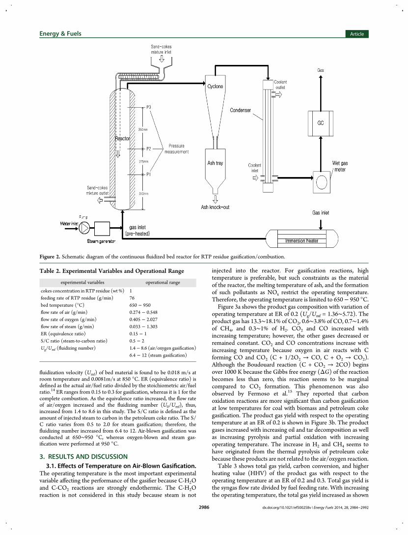
2.2. Experimental Apparatus and Procedure. A schematicdiagram of the continuous fluidized bed reactor used for RTP residuegasification/combustion is shown in Figure 2. The reactor consists ofinlet/outlet feeder, preheater, main reactor, cyclone, ash tray, condenser,wet gas meter, and gas analyzer (GC; gas chromatography). For thesteam gasification, the steam generator equipped with peristaltic pump(Masterflex L/S digital drive) is attached in front of the distributor. Thepressure and temperature of the reactor were measured at each position(P1, P2, and P3) inside the reactor by pressure transducers andthermocouples. The bed height and inventory were estimated bymeasuring pressure inside the reactor. Fine particles were separated inthe cyclone. The flow rate of the product gas that passed through thecondenser was measured at the temperature of 20 °C and atmosphericcondition (1 atm) using a wet gas meter in real time. Next, the productgas (H2, CO, CO2, and CH4) and dilute gas (O2, N2) concentrationswere measured using GC (HP 7890) with TCD (thermal conductivitydetector) with two columns (Molecular Sieve 5A, Porapak Q).
At the start of the experiment, 500 g of silica sand particles was placedin the reactor. Nitrogen that was preheated up to 230 °Cwas supplied tothe reactor through a sintered metal plate distributor. The reactor waselectrically heated to the target temperature using a furnace. When thetarget temperature was reached, air/oxygen/steam was introduced intothe distributor and then the petroleum coke/sand mixture was supplied.The gasification/combustion occurs inside the reactor. The bedpressure (P1, P2, and P3) was monitored to ensure that the amountsof coke/sand mixture that were supplied and drained were the same.When the bed pressure increased or decreased, the speed of the screwfeeder was adjusted to ensure that steady state was maintained inside thereactor. The product gas composition was analyzed by GC once the flowrate of product gas, as measured by a wet gas meter, reached steady stateapproximately 30 min after changing the experimental variables.
Experimental variables and their operational ranges are shown inTable 2. The petroleum coke/sand mixture was supplied and drained ata feed rate of 76 g/min. The reactor temperature ranged from 650 to 950°C, which is common for a fluidized bed reactor. The minimum
Figure 1. Schematic diagram of the dual circulating fluidized bed reactorfor extra-heavy oil fraction upgrading process.
Table 1. Proximate, Ultimate Analysis and Calorific Value ofthe Samples
samples petroleum coke simulated RTP residue
proximate analysis (wt %, as received)moisture 0.34 0.01volatile matter 12.36 0.12fixed carbon 86.57 0.87ash 0.73 99
ultimate analysis (wt %, db)C 85.67 0.86H 3.95 0.04Oa 1.12 0.01N 1.05 0.01S 7.48 0.08calorific value (kcal/kg) 8540
aCalculated by difference.
Energy & Fuels Article
dx.doi.org/10.1021/ef500258v | Energy Fuels 2014, 28, 2984−29922985
fluidization velocity (Umf) of bed material is found to be 0.018 m/s atroom temperature and 0.0081m/s at 850 °C. ER (equivalence ratio) isdefined as the actual air/fuel ratio divided by the stoichiometric air/fuelratio.14 ER ranges from 0.15 to 0.3 for gasification, whereas it is 1 for thecomplete combustion. As the equivalence ratio increased, the flow rateof air/oxygen increased and the fluidizing number (U0/Umf), thus,increased from 1.4 to 8.6 in this study. The S/C ratio is defined as theamount of injected steam to carbon in the petroleum coke ratio. The S/C ratio varies from 0.5 to 2.0 for steam gasification; therefore, thefluidizing number increased from 6.4 to 12. Air-blown gasification wasconducted at 650∼950 °C, whereas oxygen-blown and steam gas-ification were performed at 950 °C.
3. RESULTS AND DISCUSSION3.1. Effects of Temperature on Air-Blown Gasification.
The operating temperature is the most important experimentalvariable affecting the performance of the gasifier because C-H2Oand C-CO2 reactions are strongly endothermic. The C-H2Oreaction is not considered in this study because steam is not
injected into the reactor. For gasification reactions, hightemperature is preferable, but such constraints as the materialof the reactor, the melting temperature of ash, and the formationof such pollutants as NOx restrict the operating temperature.Therefore, the operating temperature is limited to 650− 950 °C.Figure 3a shows the product gas composition with variation of
operating temperature at ER of 0.2 (Ug/Umf = 1.36∼5.72). Theproduct gas has 13.3∼18.1% of CO2, 0.6∼3.8% of CO, 0.7∼1.4%of CH4, and 0.3∼1% of H2. CO2 and CO increased withincreasing temperature; however, the other gases decreased orremained constant. CO2 and CO concentrations increase withincreasing temperature because oxygen in air reacts with Cforming CO and CO2 (C + 1/2O2 → CO, C + O2 → CO2).Although the Boudouard reaction (C + CO2 → 2CO) beginsover 1000 K because the Gibbs free energy (ΔG) of the reactionbecomes less than zero, this reaction seems to be marginalcompared to CO2 formation. This phenomenon was alsoobserved by Fermoso et al.15 They reported that carbonoxidation reactions are more significant than carbon gasificationat low temperatures for coal with biomass and petroleum cokegasification. The product gas yield with respect to the operatingtemperature at an ER of 0.2 is shown in Figure 3b. The productgases increased with increasing oil and tar decomposition as wellas increasing pyrolysis and partial oxidation with increasingoperating temperature. The increase in H2 and CH4 seems tohave originated from the thermal pyrolysis of petroleum cokebecause these products are not related to the air/oxygen reaction.Table 3 shows total gas yield, carbon conversion, and higher
heating value (HHV) of the product gas with respect to theoperating temperature at an ER of 0.2 and 0.3. Total gas yield isthe syngas flow rate divided by fuel feeding rate. With increasingthe operating temperature, the total gas yield increased as shown
Figure 2. Schematic diagram of the continuous fluidized bed reactor for RTP residue gasification/combustion.
Table 2. Experimental Variables and Operational Range
experimental variables operational range
cokes concentration in RTP residue (wt %) 1feeding rate of RTP residue (g/min) 76bed temperature (°C) 650 − 950flow rate of air (g/min) 0.274 − 0.548flow rate of oxygen (g/min) 0.405 − 2.027flow rate of steam (g/min) 0.033 − 1.303ER (equivalence ratio) 0.15 − 1S/C ratio (steam-to-carbon ratio) 0.5 − 2Ug/Umf (fluidizing number) 1.4− 8.6 (air/oxygen gasification)
6.4 − 12 (steam gasification)
Energy & Fuels Article
dx.doi.org/10.1021/ef500258v | Energy Fuels 2014, 28, 2984−29922986

in Table 3. Carbon conversion is defined as the amount of carbonin the product gas divided by the amount of carbon in thepetroleum coke.16 The carbon conversion increased from 0.17 to
0.37 when the operating temperature increased from 650 to 950°C due to the increased product gases from pyrolysis andgasification. However, this carbon conversion is relatively small
Figure 3. (a) Product gas composition and (b) gas yield with variation of operating temperature at an ER of 0.2.
Table 3. Total Gas Yield, Carbon Conversion, and HHV of Product Gas on Air-Blown Gasification (ER = 0.2, 0.3)
total gas yield (m3/kg) carbon conversion (unitless) calorific value of product gas (kcal/m3)
bed temperature (°C) ER = 0.2 ER = 0.3 ER = 0.2 ER = 0.3 ER = 0.2 ER = 0.3
650 0.26 0.43 0.17 0.26 131.9 72.3750 0.27 0.44 0.18 0.27 160.4 132.7850 0.36 0.52 0.23 0.31 165.8 141.7950 0.38 0.59 0.25 0.37 277.2 188.6
Energy & Fuels Article
dx.doi.org/10.1021/ef500258v | Energy Fuels 2014, 28, 2984−29922987

compared to those of coal and biomass gasification,16 indicatingthat the operational temperature or oxygen flow rate (ER) shouldbe increased to achieve high carbon conversion. The calorificvalue increased with increasing operating temperature andranged from 72.3 to 277.2 kcal/m3. Compared with the HHV ofproduct gas from conventional coal/biomass air-blown fluidizedbed gasifiers14 (1000−1200 kcal/m3), the HHV of the productgas in this study is relatively low. The petroleum coke gasificationhas been reported using a high pressure gasifier operated at 1.5MPa and 1000 °C15 and an entrained flow gasifier operated at1400−1600 °C.17 The HHV of product gas were 1477−1590kcal/m3 and 1363−1800 kcal/m3, respectively.
The main reason for the low HHV of the product gas is thenitrogen dilution effect (approximately 70∼80% N2) in theproduct gas. In addition to this, petroleum coke has a lowerreactivity at the corresponding temperature with the fluidizedbed.
3.2. Effects of ER on Air-Blown Gasification. As thepetroleum coke produces the product gas mainly by reactionwith oxygen, the ER is another important experimental variablein addition to the operating temperature. Figure 4a shows theproduct gas composition with variation of ER at an operatingtemperature of 850 °C. As the ER increased from 0.15 to 0.3, thefluidizing number (Ug/Umf) increased from 4.3 to 8.6, andtherefore, the residence time of petroleum coke/sand mixture
Figure 4. (a) Product gas composition and (b) gas yield with variation of ER at the operating temperature of 850 °C.
Energy & Fuels Article
dx.doi.org/10.1021/ef500258v | Energy Fuels 2014, 28, 2984−29922988

inside the reactor decreased. The product gas has 15.8∼17.9% ofCO2, 0.6∼3% of CO, 0.7∼1.7% of CH4, and 0.6∼1.6% of H2.CO2 concentration increased drastically with increasing ER,whereas CO, CH4, and H2 concentrations decreased a little withrespect to ER as observed from air gasification of polypropyleneplastic waste.18
The product gas yield with variation of ER at an operatingtemperature of 850 °C is shown in Figure 4b. As the ERincreased, CO2 increased remarkably, whereas other gas yieldsdecreased or remained constant. As observed in the previoussection, CO2 concentration increased with increasing ER becausethe CO2 formation reaction (C + O2 → CO2, CO + 1/2O2 →CO2) dominated any other reactions. H2 and CH4 yielddecreased due to shortened residence time for petroleumcoke/sand mixture pyrolysis inside the reactor.Table 4 shows total gas yield, carbon conversion, and HHV of
the product gas with variation of ER. With increasing ER, the
total gas yield increased from 0.19 to 0.43 m3/kg at 650 °C andfrom 0.31 to 0.52 m3/kg at 850 °C, respectively. As ER increased,the carbon conversion increased from 0.11 to 0.26 at 650 °C andfrom 0.17 to 0.31 at 850 °C due to increased gas yield frompetroleum coke pyrolysis and gasification. As the ER increased,the calorific value of the product gas decreased from 148.4 to 72.3kcal/m3 at 650 °C and from 303.2 to 141.7 kcal/m3 at 850 °C,respectively. This is because the increment of CO2, non-combustible gas, is larger than the combustible gases such as CO,H2, and CH4. A decrease in HHV of the product gas was alsoobserved for a coal/petroleum mixture17 and for air gasificationof polypropylene plastic waste18 due to the consumption ofhydrocarbons by combustion. However, the calorific value of theproduct gas in this study is still lower than those of otherstudies.16−19
3.3. Oxygen-Blown Gasification Characteristics. Asdescribed in the previous section for air-blown gasification, thecarbon conversion and calorific value of the product gas in thisstudy are low because of the dilution effect of nitrogen and thelow reactivity of petroleum coke. Therefore, oxygen-blowngasification was conducted to prevent the nitrogen dilution effectand to increase the carbon conversion. The product gascomposition with respect to ER at an operating temperature of950 °C is shown in Figure 5a. As the ER increased from 0.2 to 1.0,the fluidizing number increased from 1.4 to 6.4. The product gashas 60.2∼95.7% of CO2, 0∼4.6% of CO, 0∼1.4% of CH4, and0.1∼4.3% of H2. The oxygen flow rate into the reactor increasedwith increasing ER, producing as much as 95% of CO2 for ER =0.7.Figure 5b shows the product gas yield with respect to ER at an
operating temperature of 950 °C. As ER increased, the yields ofmost of the product gases increased. Among these, CO2 yieldincreased significantly,19 while the yield of combustible gases
(CO, CH4, and H2) show their maximum values at an ER of 0.4.When the ER is higher than 0.4, the combustion reaction isdominant over gasification and combustible gases decreased.The total gas yield, carbon conversion, and HHV of product
gas with variation of ER at an operating temperature of 950 °Care shown in Table 5. The total gas yield increased from 0.38 to1.72 m3/kg with increasing ER. As ER increased, the carbonconversion increased from 0.15 (ER = 0.2) to 0.93 (ER = 1). It isfound that the typical carbon conversion for gasification (>0.9) isachieved for petroleum coke with complete combustion (ER =1). However, the HHV of the product gas with completecombustion is almost zero (0.3 kcal/m3). As ER increases from0.4 to 1.0, the HHV of the product gas decreased from 300.8 to0.3 kcal/m3. The maximum yield of combustible gas at ER = 0.4resulted in the maximum HHV of the product gas. It can beconcluded that the optimum ER for the maximum HHV of theproduct gas and maximum carbon conversion are 0.4 and 1.0,respectively.
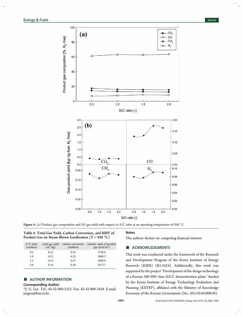
3.4. Steam-Blown Gasification Characteristics. Steam isused as a gasifying agent to increase the calorific value of theproduct gas. The product gas composition and gas yield withrespect to S/C ratio at an operating temperature of 950 °C isshown in Figure 6a and b. The product gas has 61.3∼63.7% ofH2, 15.6∼17.5% of CH4, 12.4∼14.3% of CO2, and 6.9∼8.6% ofCO. The variation of product gas composition and gas yield withincreasing S/C ratio is marginal as shown in Figure 6. Withincreasing S/C ratio, more steam is introduced into the reactorand, therefore, steam gasification reactions (C + H2O → H2 +CO, C + 2H2O → 2H2 + CO2) are favored. However, thefluidizing number also increases, which means that the residencetime inside the reactor also decreases. These two factorsinfluence the product gas composition and gas yield. Total gasyield, carbon conversion, and the HHV of the product gas withvariation of S/C ratio at an operating temperature of 950 °C areshown in Table 6. The total gas yield is less than 0.15 m3/kg andthe carbon conversion is less than 0.37 because oxygen is notinjected into the reactor. Based on the previous results of air andoxygen gasification, it is found that the concentration of oxygen isthe most important factor to affect the carbon conversion. Asshown in Figure 6, the remarkable trend that was previouslyobserved with variation of S/C ratio is not seen. The calorificvalue of the product gas is higher than 3600 kcal/m3, which ishigher than results from previous entrained flow gasification of apetroleum coke/coal mixture17 and lab-scale steam gasificationof petroleum coke.19 It appears therefore that the calorific valueof the product gas can be increased.
4. CONCLUSIONSIn the present study, a continuous fluidized bed reactor with themaximum capacity of 10 kg/h (0.05 m I.D. × 1.2 m high) wasdesigned and constructed for gasification/combustion ofpetroleum coke in the presence of sand. Air, oxygen, andsteam were used as gasifying agents. The results of gasification,such as product gas composition, carbon conversion, gas yield,and higher heating value of product gas, are determined withvariation of reactor temperature, ER (equivalence ratio), S/C(steam-to-carbon) ratio, and gas velocity in the reactor.As the operating temperature and ER increased, the yields of
H2 and CO2 increased, indicating that the carbon conversionincreased. When air is used as gasification agent, the calorificvalue of the product gas ranged from 72.3 to 303.2 kcal/m3, andthe carbon conversion was less than 0.37, both of which are muchlower than the values from general gasifiers. In the case of O2-
Table 4. Total Gas Yield, Carbon Conversion, and HHV ofProduct Gas on Air-Blown Gasification (T = 650, 850 °C)
total gas yield(m3/kg)
carbonconversion(unitless)
calorific value ofproduct gas(kcal/m3)
equivalence ratio(unitless)
T =650 °C
T =850 °C
T =650 °C
T =850 °C
T = 650°C
T = 850°C
0.15 0.19 0.31 0.11 0.17 148.4 303.20.2 0.26 0.36 0.17 0.23 131.9 165.80.25 0.36 0.45 0.20 0.29 86.2 161.10.3 0.43 0.52 0.26 0.31 72.3 141.7
Energy & Fuels Article
dx.doi.org/10.1021/ef500258v | Energy Fuels 2014, 28, 2984−29922989

blown gasification, carbon conversion of 0.93 could be achievedwith increasing ER. However, most of the petroleum coke is
transformed into CO2, and notably little combustible gas could
be obtained at high ER. A relatively high calorific value (382.5
kcal/m3) of product gas is obtained with an ER of 0.4 with
maximum yield of the combustible gases. The calorific value of
the product can be increased to 3739 kcal/m3 with steam as a
gasifying agent.On the basis of these results, the optimum operating
conditions can be determined for petroleum coke/sand mixture
gasification/combustion in an extra-heavy oil fraction upgrading
process.
Figure 5. (a) Product gas composition and (b) gas yield with respect to ER at an operating temperature of 950 °C.
Table 5. Total Gas Yield, Carbon Conversion, and HHV ofProduct Gas on Oxygen Blown Gasification (T = 950 °C)
equivalenceratio (unitless)
total gas yield(m3/kg)
carbonconversion(unitless)
calorific value ofproduct gas (kcal/m3)
0.2 0.38 0.15 300.80.4 0.75 0.45 400.90.7 1.28 0.79 121.21.0 1.72 0.93 0.3
Energy & Fuels Article
dx.doi.org/10.1021/ef500258v | Energy Fuels 2014, 28, 2984−29922990
■ AUTHOR INFORMATIONCorresponding Author*J. G. Lee. Tel.: 82-42-860-3353. Fax: 82-42-860-3428. E-mail:[email protected].
Notes
The authors declare no competing financial interest.
■ ACKNOWLEDGMENTS
This work was conducted under the framework of the Research
and Development Program of the Korea Institute of Energy
Research (KIER) (B3-2424). Additionally, this work was
supported by the project “Development of the design technology
of a Korean 300 MW class IGCC demonstration plant,” funded
by the Korea Institute of Energy Technology Evaluation and
Planning (KETEP), affiliated with the Ministry of Knowledge
Economy of the Korean Government (No. 2011951010001B).
Figure 6. (a) Product gas composition and (b) gas yield with respect to S/C ratio at an operating temperature of 950 °C.
Table 6. Total Gas Yield, Carbon Conversion, and HHV ofProduct Gas on Steam Blown Gasification (T = 950 °C)
S/C ratio(unitless)
total gas yield(m3/kg)
carbon conversion(unitless)
calorific value of productgas (kcal/m3)
0.5 0.15 0.35 3738.61.0 0.12 0.32 3689.31.5 0.14 0.37 3669.92.0 0.14 0.36 3672.7
Energy & Fuels Article
dx.doi.org/10.1021/ef500258v | Energy Fuels 2014, 28, 2984−29922991

■ REFERENCES(1) Kayukawa, T.; Nagamatsu, S. Current upgrading technology ofheavy oil and unconventional crude. J. Jpn. Inst. Energy 2010, 89, 1042−1051.(2) Meyer, R. F.; Attanasi, E. D. Heavy oil and natural bitumen -strategic petroleum resources. U. S. Geological Survey Fact Sheet 2003,70−03, http://pubs.usgs.gov/fs/fs070-03/.(3) Jeon, S. G; Kwak, N. S.; Rho, N. S.; Ko, C. H.; Na, J. G.; Yi, K. B.Catalytic pyrolysis of athabasca bitumen in H2 atm using microwaveirradiation. Chem. Eng. Res. Des. 2012, 90, 1292−1296.(4) SFA Pacific, Inc. Upgrading heavy crude oils and residues totransportation fuels: technology, economics, and outlook - Phase 8.2009. http://www.sfapacific.com/petroleum_processing_program.shtml (accessed Jan 2014).(5) Ivanhoe Energy. HTL Integrated heavy oil production; CanadianEmbassy: Tokyo, Japan, 2008.(6) ETX Systems, IYQ Upgrading −An industry altering technologyfor primary upgrading of heavy oil.World Heavy Oil Congress. Puerto LaCruz, Venezuela, 2009.(7) Hedrick, B. W.; Seibert, K. D.; Crewe, C. A new approach to heavyoil and bitumen upgrading. UOP LLC and Meta Petroleum; UOP LLC.:Des Plaines, IL, 2006; http://www3.kfupm.edu.sa/catsymp/symp16th/pdf%20papers/09%20opdorp.pdf.(8) McCaffrey, D. S; Hammond, D. G; Patel, V. R. Fluidised bedcoking−utilizing bottom of the barrel. Digital Refining: Hopesay, U. K.,1998; http://www.digitalrefining.com/data/articles/file/409871624.pdf.(9) Seo, M.W.; Guahk, Y. T.; Yoon, S. J.; Ra, H. W.; Lee, J. G.; Nho, N.S.; Kim, S. D. Gasification characteristics of petroleum coke in a fluidizedbed reactor. Proc. Asia-Pac. Forum Renewable Energy. Jeju, Korea, 2012.(10) Pfeifer, C.; Rauch, R.; Hofbauer, H. In-Bed Catalytic tar reductionin a dual fluidized bed biomass steam gasifier. Ind. Eng. Chem. Res. 2004,43, 634−640.(11) Seo, M. W.; Nguyen, T. C. B.; Lim, Y. I; Kim, S. D; Park, S. W.;Song, B. H.; Kim, Y. J. Solid circulation and pressure drop characteristicsof a dual circulating fluidized bed reactor: experiments and CFDsimulation. Chem. Eng. J. 2011, 168, 803−811.(12) Koppatz, S.; Pfeifer, C.; Rauch, R.; Hofbauer, H.; Marquard-Moellenstedt, T.; Specht, M. H2 rich product gas by steam gasification ofbiomass with in situ CO2 absorption in a dual fluidized bed system of 8MW fuel input. Fuel Proc. Tech. 2009, 90, 914−921.(13) Proll, T.; Kolbitsch, P.; Bolhar-Nordenkampf, J.; Hofbauer, H. Anovel dual circulating fluidized bed system for chemical loopingprocesses. AIChE J. 2009, 55, 3255−3266.(14) Kim, Y. D.; Yang, C.W.; Kim, B. J.; Kim, K. S.; Lee, J. W.; Moon, J.H.; Yang, W.; Yu, T. U.; Lee, U. D. Air-blown gasification of woodybiomass in a bubbling fluidized bed gasifier. Appl. Energy 2013, 112,414−420.(15) Fermoso, J.; Arias, B.; Plaza, M. G.; Pevida, C.; Rubiera, F.; Pis, J.J.; García-Pena, F.; Casero, P. High-pressure co-gasification of coal withbiomass and petroleum coke. Fuel Proc. Tech. 2009, 90, 926−932.(16) Seo, M. W.; Goo, J. H.; Kim, S. D.; Lee, S. H.; Choi, Y. C.Gasification characteristics of coal/biomass blend in a dual circulatingfluidized bed reactor. Energy Fuels 2010, 24, 3108−3118.(17) Lee, S. H.; Yoon, S. J.; Ra, H. W.; Son, Y. I.; Hong, J. C.; Lee, J. G.Gasification characteristics of coke and mixture with coal in anentrained-flow gasifier. Energy 2010, 35, 3239−3244.(18) Xiao, R.; Jin, B.; Zhou, H.; Zhong, Z.; Zhang, M. Air gasification ofpolypropylene plastic waste in fluidized bed gasifier. Energ. Convers.Manage. 2007, 48, 778−786.(19) Yoon, S. J.; Choi, Y. C.; Lee, S. H.; Lee, J. G. Steam gasificationcharacteristics of oil sand coke in a lab-scale fixed bed gasifier. J. KoreanInd. Eng. Chem. 2009, 20, 62−66.
Energy & Fuels Article
dx.doi.org/10.1021/ef500258v | Energy Fuels 2014, 28, 2984−29922992