gc0075 - national grid
TRANSCRIPT

1 of 58
GC0075 Industry
Consultation
20 January 2016
Version 2.0
Page 1
GC0075 – Hybrid STATCOMs / SVCs This Consultation seeks views on proposals to modify the Grid Code. The modifications are intended to clarify the continuous voltage control requirements applicable to Power Park Modules with the aim of facilitating the deployment of Hybrid STATCOM/SVC solutions without eroding dynamic voltage control capability available to the System Operator. This includes revising the transient voltage control requirement, defining a repeatability criterion, and clarifying the response expected from switched reactive compensation components during faults.
Published on: 20 January 2016
Length of Consultation: 20 Working Days
Responses by: 17 February 2016
National Grid recommends:
Implementation of the changes proposed to the Grid Code
High Impact:
None
Medium Impact:
Owners and Developers of Power Park Modules; Manufacturers of
Hybrid STATCOMs/SVCs
Transmission Licensees
Low Impact:
None
Stage 02: Industry Consultation
Grid Code
01 Workgroup
Report
02 Industry Consultation
03 Report to the Authority

GC0075 Industry
Consultation
20 January 2016
Version 2.0
Page 2 of 58
Contents
About this document .............................................................................. 3 1
Executive Summary ................................................................................ 4 2
Purpose & Scope of Workgroup ........................................................... 6 3
Background ............................................................................................. 7 4
Grid Code Compliance Issues Associated with Hybrid 5
STATCOMs/SVCs ......................................................................................... 10
Requirements for Repeatability ........................................................... 17 6
Fault Ride Through and Post Fault Voltage Recovery ..................... 35 7
Other Issues ........................................................................................... 37 8
Implementation Considerations .......................................................... 39 9
Conclusions and Recommendations ................................................. 40 10
Assessment ........................................................................................... 41 11
Responding to this Consultation ........................................................ 43 12
Annex 1 – Grid Code Issue Paper............................................................... 44
Annex 2 – Terms of Reference .................................................................... 47
Annex 3 - Proposed Legal Text ................................................................... 49
Annex 4 – Register of Attendance .............................................................. 54
Annex 5 – Manufacturers Survey ............................................................... 55
Annex 6 – Fault Statistics ............................................................................ 56
Annex 5 – Acronyms and Abbreviations ................................................... 57
Any Questions?
Contact:
Rob Wilson
Robert.Wilson2
@nationalgrid.com
01926 653398
Proposer:
Antony Johnson
National Grid Electricity
Transmission plc
Antony.Johnson
@nationalgrid.com
01926 655466

GC0075 Industry
Consultation
20 January 2016
Version 2.0
Page 3 of 58
About this document 1
This Industry Consultation outlines the information required for interested parties
to form an understanding of a defect within the Grid Code and seeks the views of
interested parties in relation to the issues raised by this document.
Parties are requested to respond by 17 February 2016 to
Document Control
Version Date Author Change Reference
1.00 17-12-2015 National Grid Draft submitted to the Grid
Code Review Panel
2.00 20-01-2016 National Grid Final version for
consultation

GC0075 Industry
Consultation
20 January 2016
Version 2.0
Page 4 of 58
Executive Summary 2
Under CC.6.3.8 of the Grid Code, Power Park Modules, DC Converters and 2.1OTSDUW Plant and Apparatus are required to control the voltage at the Grid Entry Point, User System Entry Point, or Interface Point as applicable. In addition the performance requirements of the voltage control system are defined in Appendix 7 of the Grid Code connection conditions.
A number of Generators have questioned the definition of continuous voltage control 2.2as derogations for some hybrid reactive compensation plant were being considered as a result of Compliance Testing. This issue was consequently referred to the Grid Code Review Panel.
In response, the Grid Code Review Panel initially expressed the view that all plant 2.3connected after 1 of January 2013 should be capable of responding over its full reactive range to two successive events occurring at an interval of 15 seconds or greater. In addition the Grid Code Review Panel recommended that a workgroup is convened to investigate these issues further and report its findings back to the Panel.
To address these concerns, the workgroup considered a variety of data relating to 2.4studies, statistical analysis of weather events, technical solutions and commercial implications. The Workgroup’s objective was to define an appropriate level of capability to ensure the robustness and integrity of the Transmission System whilst at the same time maintaining technological neutrality and ensuring hybrid STATCOMs and SVCs could be used by developers as a solution to meet any proposed requirements.
The two specific issues which came to light during Compliance Testing were in 2.5relation to the switching of the shunt devices and were:
(i) the time taken to charge the operating mechanism of the circuit breaker could be significant e.g. the spring recharge time; and that
(ii) after switching a shunt capacitor out of service, there may be a significant delay while the capacitor is discharged before the plant can be switched into service again.
Both issues mean that the shunt device is unable to provide voltage control if called 2.6upon twice or more in a short time. Where this period of unavailability cannot be accommodated by the short term capability of the equipment there is a shortfall in the reactive capability available to contribute to the control of system voltage. The time delay before full reactive capability is restored exceeds 10 minutes in some cases.
During the meetings, various other technical issues were raised and discussed 2.7including communications delays, and short term ratings of equipment.
In addition to the above, consideration was also given to the fault ride through 2.8capability of the switched reactive elements as compliance testing had also identified cases where switches were opened under low system voltage conditions. This was a concern because low voltage depression can be seen over a wide geographic area when a fault is applied and may result in a considerable reduction in reactive power post fault, exacerbating either high or low voltage conditions and increasing the possibility of voltage collapse.
Proposed Solution
The proposal was developed by the workgroup after consideration of the issues 2.9raised by generators, developers and manufacturers alongside those raised by Transmission Licensees. The proposed requirements are intended to strike a balance between the minimum need of the Transmission System and cost impacts on developers and manufacturers. The proposed solution represents the lowest cost option of the potential solutions considered by the workgroup.

GC0075 Industry
Consultation
20 January 2016
Version 2.0
Page 5 of 58
The proposed solution asks for voltage control to be provided with a repeat 2.10capability at 15 seconds but limited to 5 events in 5 minutes up to a maximum of 25 events a day. Restrictions on reactive capability that may arise if the 25 events have been exceeded have to be notified to NGET in accordance with BC2.5.3.2, and BC2.6.1 in line with existing practice for managing shortfalls in reactive capability.
The proposed change provides assurance of equipment performance in planning 2.11and operational time scales, giving the operators confidence that equipment’s is able to respond within DAR timescales. It also clarifies the procedures that Users have to follow to notify NGET with any restrictions on reactive capability.
The workgroup recommended that its proposals should proceed to consultation. The 2.12legal text, as amended in response to the feedback from the Grid Code Review Panel, is provided in Annex 3 of this document. The text includes a modification to CC.A.7.2.3.1 to clarify the existing requirements, a new clause CC.A.7.2.3.2, which defines the repeatability performance requirements, and modifications to CC.6.3.15.1 and CC6.3.15.2, which state switched reactive components should ride through a fault without opening or closing switches. This draft legal text addresses:
• The timeframe required for a Power Park Module or Reactive Compensation equipment to change its reactive power output from full lead to full lag or vice versa.
• Clarifications to the settling time following a disturbance • The addition of a repeatability criteria requiring 5 consecutive responses in
any five minute period, no more than 15 seconds apart. • A criteria which limits the maximum number of events (ie unity to 90% full
leading or unity to 90% full lagging) to a maximum of 25 events in any 24 hour period.
• Where the daily limit of 25 events is exceeded the requirement to inform NGET of the reduction in reactive capability
• Amendments to the fault ride through requirements clarifying reactive compensation equipment and requirements preventing them from switching during a fault ride through sequence.
Impact on Users
This consultation document represents the views of the workgroup which has sought 2.13to find a solution that strikes the right balance between imposing requirements upon new connectees and impacting system security and resilience. A majority of the workgroup members who expressed a view believe the changes address the original Grid Code defect.
The change proposed address concerns over the clarity of current requirements and 2.14allows manufacturers and developers to compete on equitable basis. Whereas some concerns that the requirements might result in an increase in the cost, the results of a manufacturers survey indicated that this cost implications are marginal.

GC0075 Industry
Consultation
20 January 2016
Version 2.0
Page 6 of 58
Purpose & Scope of Workgroup 3
Overview
An issue was initially raised at the Grid Code Review Panel in 2010 in relation to CC 3.16.3.6. This requires that all generators should be capable of contributing to voltage control by continuous changes of reactive power. In addition, CC.6.3.2 defines the reactive capability required from Power Park Modules at the Connection Point whilst CC.6.3.8 and Appendix 7 of the Grid Code Connection Conditions defines the necessary voltage control and performance requirements.
A number of Generators questioned the definition of continuous voltage control and 3.2the fault ride through requirements with respect to the reactive compensation plant installed as part of a Power Park Module.
After an initial Workshop meeting in September 2013 a Workgroup was established 3.3in November 2013.
The Workgroup was tasked to consider the following points: 3.4
The performance of Hybrid Static Compensators and comparable 3.4.1equipment with respect to repeatability and the supply of reactive current during a fault.
The performance required from voltage control equipment within Power 3.4.2Park Modules to control voltage on the networks, during and after secured events, and in the event of a wider system disturbance.
In addition to the points in 3.4, the workgroup discussed the clarification of the 3.5existing transient voltage control requirements.
The interactions between this section and the Grid Code Connection Conditions and 3.6the relevant provisions within the European Network Codes Requirements for Generators (RfG) and HVDC Connections were also considered to ensure that the proposals do not conflict with future requirements.
Timescales
The work group was scheduled to report back to the Grid Code Review Panel at 3.7regular intervals with the aim of completing a report at the end of the first year.
Five workgroup meetings were held over a period of just over a year after which, a 3.8report summarising the Workgroup discussions and conclusions was submitted to the Grid Code Review Panel in July 2015.
The final work group meeting was held in April 2015 and it was decided to submit 3.9the report to the Grid Code Review Panel.
Following feedback from the Grid Code Review Panel, the legal text proposed, 3.10Annex 3, was revised.
M1 – 15 May 2014
M2 –07 August 2014
M3 – 22 October 2014
M4 – 26 January 2015
M5 - 27 April 2015
Workgroup Meeting
Dates

GC0075 Industry
Consultation
20 January 2016
Version 2.0
Page 7 of 58
Background 4
This section describes the development of this issue from initial identification in 2010 4.1to the beginning of the Workgroup.
May 2010 Panel Meeting - The issue was first raised in the GCRP minutes under 4.2‘Any Other Business’ at the Grid Code Review Panel. A representative for the Wind Farm developers highlighted an issue relating to MSC’s used in PPM voltage control systems.
September 2010 Panel Meeting - NGET submitted a paper to the September panel 4.3meeting “GCRP pp10/24 Voltage Control and Fault Ride Through”. The key recommendations were:
• Sites with a Completion Date prior to 1 January 2013 and have a
performance such that switch recharge time (close-open-close) less than 15 seconds and capacitor discharge time less than 2 seconds will be accepted.
• Sites with a Completion Date prior to 1 January 2013 and have longer unavailability would be asked to seek a derogation.
• Sites with a completion date after 1 January 2013 would be required to have no unavailability of reactive capability.
The Grid Code Review Panel and STC Panel were asked to consider if any changes 4.4were required to either the Grid Code or / and the STC.
November 2010 Panel Meeting – NGET proposed four options. These options were: 4.5
1. Treating all affected developments as non-compliant. This would result in potentially 30 plants requiring a derogation and provides no incentive for installations with long delays to improve.
2. Adopting NGET's proposal for an interim interpretation. This would remove uncertainty for immediately affected developments
3. Amending the Grid Code to reflect NGET's proposal for an interim interpretation. This would remove uncertainty for immediately affected developments. However, there is a need to assess the wider impacts of the change.
4. Reviewing the application of hybrid solutions in meeting the Grid Code requirement on reactive power capability and voltage control. This would require an assessment of the incremental cost of 'true continuous' operation.
The Panel recommended adopting the third option. 4.6
February 2011 Panel Meeting - The issue was discussed and it was agreed to 4.7resolve the issue of interim interpretation of the Grid Code with an extraordinary meeting if necessary.
November 2011 Panel Meeting - The Panel agreed that NGET should bring forward 4.8a change to the Grid Code to clarify the meaning of “continuous” in relation to voltage control and switched capacitors/ reactors.
Additionally it was determined that the Panel must decide how projects should be 4.9dealt with in the meantime.
March 2011 Extraordinary Meeting of the GCRP – At this meeting a paper was 4.10submitted by a representative of the developers which made recommendations in two sections, (A) specific to this issue and (B) generic, to deal with different interpretations of the Code:
A. Provide interpretation and progress Code change process as follows:
1. Ensure that NGET bring forward a Grid Code change proposal to remove the uncertainly of interpretation of “continuous” regarding voltage control and especially in relation to capacitor switching and discharge. (NGET’s action had already been agreed at the GCRP in November 2010).

GC0075 Industry
Consultation
20 January 2016
Version 2.0
Page 8 of 58
2. Ensure that NGET perform a Cost Benefit Analysis for any changes proposed in (1) above.
3. Ensure that NGET assess the risk to the NETS of legacy plant and consider a retrospective application of the Grid Code change.
4. For existing projects or those under construction (pending the Grid Code change), define an interpretation of the current Grid Code term “continuous” in relation to voltage as either:
a. In defining “continuous” - ignore the time delay in the second switching operation of a capacitor or reactor.
Or
b. Define “continuous” in the current Grid Code to mean a minimum of 15 seconds (close-open-close) and 2 seconds (capacitor discharge) for an indefinite number of repeat operations.
Or
c. Define “continuous” in the current Grid Code to mean a minimum of 15 seconds (close-open-close) and 2 seconds (capacitor discharge) for a second switching operation with no specified requirement for a third switching operation.
5. To assess any potential discrimination issues, NGET to provide a list of all projects which have switched voltage control equipment commissioned to date, clearly showing the capabilities and indicating where NGET has demanded a change to capabilities and where FONs have been issued or have not yet been issued.
B. Make Code changes to manage different interpretations of the Code:
6. Ask NGET to bring forward a change to the General Conditions of the Grid Code to require NGET to bring to the Panel any issue of interpretation of the Grid Code where two or more Users are disputing NGET’s interpretation and for such a report to be a standing agenda item for Panel meetings.
7. Ask NGET to report under KPIs on the speed of resolution of matters of interpretation requested by Users.
8. To provide a Web based facility for Users to request such interpretations.
From the meeting minutes the Panel decided: 4.11
In confirmation of Recommendation A (1) the Panel agreed that both 4.11.1
parties should discuss the issue further and draft a Consultation document, which would apply to future projects and if necessary and justified, be proposed to apply retrospectively. The Panel agreed that Recommendations A (2) & (3) should be considered and used if appropriate.
The Panel agreed, that as existing wind farm projects original 4.11.2interpretation, as described under Recommendation A (4a), had not caused an
operational issue, these projects will not need to seek a derogation and are deemed to be compliant. Recommendation A (5) was therefore deemed unnecessary.
The Panel also agreed that there was a future issue for anticipated, larger 4.11.3plant and therefore a future change to the Grid Code was likely to be needed to provide a clear and unambiguous obligation on such plant. Such an obligation would be applied to plant connecting after a certain date. Dates ranging from 2013 to 2015 had been discussed previously but this would be subject to consultation, if found to be necessary. The Panel noted that this may also need to be applied retrospectively to all projects or some projects (e.g. above a certain size), but only subject to a clear cost benefit case.
The Panel recommended that plant that was under development should 4.11.4be designed to meet the Recommendation A (4c) criteria.

GC0075 Industry
Consultation
20 January 2016
Version 2.0
Page 9 of 58
The Panel agreed that Recommendations B (7) and (8) should be 4.11.5progressed by National Grid but not Recommendation B (6) as it would be a significant resource burden for National Grid and the industry and may not be workable.
Workshop 20 September 2013 – Manufacturers put the case for allowing the use of 4.12Hybrid STATCOM/SVCs on cost and capability grounds. National Grid stated it was not aiming to prevent the use of Hybrid STACOM/SVC’s but presents a case for improving the future performance. It is agreed that a work group should be convened to consider the matter in greater detail.
Workgroup November 2013 – First Work group meeting held to look into the issues. 4.13

GC0075 Industry
Consultation
20 January 2016
Version 2.0
Page 10 of 58
Grid Code Compliance Issues Associated with Hybrid 5STATCOMs/SVCs
Voltage Control and Reactive Power Provision
Overview of Existing Grid Code Requirements
The following extracts are from the Grid Code as presented at the workshop in 5.1September 2013. The key sections relating to the provision of continuous voltage control are highlighted.
CC.6.3.6 (b)
Each:
(i) Onshore Generating Unit; or
(ii) Onshore DC Converter (with a Completion Date on or after 1 April
2005 excluding current source technologies); or
(iii) Onshore Power Park Module in England and Wales with a Completion Date on or after 1 January 2006; or
(iv) Onshore Power Park Module in Scotland irrespective of Completion Date; or
(v) Offshore Generating Unit at a Large Power Station, Offshore DC Converter at a Large Power Station or Offshore Power Park Module at a Large Power Station which provides a reactive range beyond the
minimum requirements specified in CC.6.3.2(e) (iii),or
(vi) OTSDUW Plant and Apparatus at a Transmission Interface Point
must be capable of contributing to voltage control by continuous changes to the Reactive Power supplied to the National Electricity Transmission System or the User System in which it is Embedded.
APPENDIX 7 - PERFORMANCE REQUIREMENTS FOR CONTINUOUSLY ACTING
AUTOMATIC VOLTAGE CONTROL SYSTEMS
CC.A.7.2.2.1 The Onshore Non-Synchronous Generating Unit, Onshore DC Converter, Onshore Power Park Module or OTSDUW Plant and Apparatus shall provide continuous steady state control of the voltage at the Onshore Grid Entry Point (or Onshore User System Entry Point if Embedded) (or the Interface Point in the case of OTSDUW Plant and Apparatus) with a Setpoint Voltage and Slope characteristic as illustrated in Figure CC.A.7.2.2a..
CC.A.7.2.2.5 Should the operating point of the Onshore Non-Synchronous Generating Unit, Onshore DC Converter, OTSDUW Plant and Apparatus or Onshore Power Park Module deviate so that it is
no longer a point on the operating characteristic (figure CC.A.7.2.2a) defined by the target Setpoint Voltage and Slope, the continuously acting automatic voltage control system shall act progressively to return the value to a point on the required characteristic within 5 seconds.
CC.A.7.2.3.1 For an on-load step change in Onshore Grid Entry Point or Onshore User System Entry Point voltage, or in the case of OTSDUW Plant and Apparatus an on-load step change in Transmission Interface Point voltage, the continuously acting
automatic control system shall respond according to the following minimum criteria:

GC0075 Industry
Consultation
20 January 2016
Version 2.0
Page 11 of 58
(i) the Reactive Power output response of the Onshore Non-Synchronous Generating Unit, Onshore DC Converter, OTSDUW Plant and Apparatus or Onshore Power Park Module shall commence within 0.2 seconds
of the application of the step. It shall progress linearly although variations from a linear characteristic shall be acceptable provided that the MVAr seconds delivered at any time up to 1 second are at least those that would result from the response shown in figure CC.A.7.2.3.1a.
(ii) the response shall be such that, for a sufficiently large step, 90% of the full reactive capability of the Onshore Non-Synchronous Generating Unit, Onshore DC Converter, OTSDUW Plant and Apparatus or Onshore Power Park Module, as required by CC.6.3.2 (or, if
appropriate, CC.A.7.2.2.6 or CC.A.7.2.2.7), will be produced within 1 second.
(iii) the magnitude of the Reactive Power output response produced within 1 second shall vary linearly in proportion to the magnitude of the step change
(iv) the settling time shall be no greater than 2 seconds from the application of the step change in voltage and the peak to peak magnitude of any oscillations shall be less than 5% of the change in steady state Reactive Power within this time.
(v) following the transient response, the conditions of CC.A.7.2.2 apply.
These requirements were intended to ensure that voltage control system of Power 5.2Park Modules is able to regulate the voltage at the point of connection in a manner that is similar to the Automatic Excitation Control System of a Synchronous Generating Unit. That is to ensure that Power Park Modules actively participate in regulating voltage levels on the National Electricity Transmission System following minor changes in flows caused by changes in generation and demand patterns and day-to-day actions taken on the transmission system as well as large disturbances; and that the response provided by the voltage control system is in proportion to the voltage change that initiated it.
These requirements have been interpreted differently by different manufacturers. 5.3Some have understood this as a requirement to provide equipment whose response is available at any time with no unavailability between events. Others have understood the requirement as the ability to respond to gradual changes over a long period with occasional sudden extensive changes being delivered with a linear increase.
Implementation of the Grid Code Requirements
The diagram below shows how the Grid Code requirement might typically be met for 5.4a given Power Park Module. The red lines in the diagram represent the physical connection of real and reactive power sources to the transmission system through the POC (Point of Connection). The other lines represent the measurement feedback and control signals.
To meet the requirement, single or multiple reactive sources may be used. These 5.5may include wind turbines, dynamic reactive compensation equipment such as STATCOMs or SVCs, static reactive compensation equipment such as capacitors and reactors or any other sources of reactive power. This is illustrated by Figure 1.
A Hybrid STATCOM or SVC, usually comprises a dynamic compensation element 5.6and a combination of mechanically switched capacitive and reactive elements to provide the full range of control required to meet the Grid Code as shown in Figure 2.

GC0075 Industry
Consultation
20 January 2016
Version 2.0
Page 12 of 58
Figure 1: Typical Voltage Control Methodology
It was noted that, due to the comparatively slow response of mechanical switchgear, 5.7hybrid STATCOM/SVC solutions are not able to meet the strict specifications Transmission Licensees require their dynamic voltage control equipment to meet and hence are not likely to be deployed as transmission plant.
Typical Hybrid SVC / STATCOM Operating Ranges (50% or 60% of the steady state reactive power produced by the capacitors and reactors)
6 or 13kV
CB1 CB2 CB3 CB4 Convertor
6 or 13kV
CB2CB1 Convertor
Double switched capacitor / reactor
Single switched capacitor / reactor
100% Reactive Lead(0.95 leading PF atRated MW)
100% Reactive Lag(0.95 lagging PF atRated MW)
100% Reactive Lead(0.95 leading PF atRated MW)
100% Reactive Lag(0.95 lagging PF atRated MW)
Unity PF
Unity PF
CB2&4 Closed
CB2 Closed
All CB’s Open
CB1 Closed
CB1&3 Closed
All CB’s Open
CB2 Closed
CB1 Closed
Figure 2: Typical SVC Steady State Operating Methodology
Potential Restrictions on Hybrid STATCOMs/SVCs
The operational restrictions on hybrid STATCOMs/SVCs discussed in this document 5.8arise because of the restrictions associated with switching capacitors and reactors in and out of service. This includes the following issues:
Spring recharge time limits the opening and closing of mechanical switches. 5.8.1This typically ranges from less than 1 second for a vacuum interrupter to about 15 seconds for typical HV switchgear.
The need ensure that a capacitor is completely discharged before it could be 5.8.2reconnected. This is typically achieved by discharge circuits that are only rated for one or two operations after which they require a cooling off period.

GC0075 Industry
Consultation
20 January 2016
Version 2.0
Page 13 of 58
Frequent switching may increase wear and tear of switchgear. This would 5.8.3eventually affect operational costs due to the increased maintenance and reduce the lifetime of equipment which is typically limited to 10000 to 100000 switching operations.
The workgroup discussed potential methods of addressing these restrictions 5.9including “point on wave” switching solutions, offered by some independent switch controller manufacturers. However, it was noted that this incurs some extra cost as the poles of the switch must be independently controlled.
Impact on performance
Spring recharge times and capacitor discharge times may result in 5.10STATCOMs/SVCs requiring some recovery time before being able to switch a capacitor or reactor that has just been switched out back into service.
The heating effect and the rating of capacitor discharge circuits may limit the number 5.11of times a capacitor could be switched out and consequently returned back to service over a short period of time.
Due to these two factors, a Power Park Modules that utilise a hybrid 5.12STATCOM/SVC to meet their reactive capability requirements specified in CC.6.3.2 might not be able to respond to a step change in voltage in accordance CC.A.7.2.3.1 if this step change would require to switch a capacitor or a reactor that has just been switched out back into service.
In addition to these restrictions, some manufacturers offer hybrid STATCOM/SVC 5.13solutions where capacitors are completely switched out of service during voltage dips. The workgroup discussed the implications of such configuration.
Specific Issues for Transmission Licensees
Transmission Licensees need to take the various events that may affect the 5.14Transmission System into account when developing and operating the National Electricity Transmission System. Examples of these events are:
Lightning Storms / High Winds Debris on a line (e.g. polythene sheet caught on a line) Operator Error Ice Forming on Conductors Cascade Tripping Events
Each of these events usually results in a short circuit that causes protection relays to 5.15disconnect the affected transmission circuit. This is usually followed by Delayed Auto Reclose trying to restore the circuit into service. The ability of the system to recover following such disturbance is largely affected by how Users Plants respond to the disturbance.
Some of these events could recur within a short period of time and with few seconds 5.16interval from each other. Users Plants that are not able to respond to such sequence of events will not be able to contribute consistently to system recovery.
In addition, some events may result in some rotor angle oscillations and/or controller 5.17interactions that would result in voltage oscillations and require a continuous response from the voltage control system of Power Park Modules.
Change in Generation Background
Historically, the majority of generation connected to the National Electricity 5.18Transmission System are Synchronous Generating Units. These units are capable of providing a dynamic response to a sequence of voltage step changes that takes

GC0075 Industry
Consultation
20 January 2016
Version 2.0
Page 14 of 58
place over a short period of time; and injecting large reactive currents into the system during faults and voltage depressions.
All Future Energy Scenarios predict a large increase in the total capacity of Power 5.19Park Modules connected to the transmission system. Many of these Power Park Modules are not designed to be capable of either responding to a sequence of voltage step changes that takes place over a short period of time or injecting large reactive currents into the system during faults and voltage depressions.
As a consequence of this change in generation background, Synchronous 5.20Generating Units will be displaced by Power Park Modules. Hence, at low demand periods, only limited number of Synchronous Generating Units may be running with the majority of demand being supplied from Power Park Modules. During these periods, there may not be sufficient support from Generating Units to assist system recovery following a fault or a series of faults.
Transmission Licensees’ Objectives
The key objective of Transmission Licensees is to ensure that the current level of 5.21reliability is maintained for as far as it is technically and economically feasible to do so. This includes, in the context of the Terms of Reference of the workgroup, ensuring that
The dynamic voltage response service available to the System Operator are 5.21.1not eroded due as Power Park Modules replace increases and that of Synchronous Generating Units decreases;
Power Park Modules are capable of responding to credible sequences of 5.21.2events that may take place over a short period of time and within short time from each other;
any subsequent reduction in reactive capability is notified to the System 5.21.3Operator such that it is taken into account when operating the system;
voltage depressions resulting from faults are not exacerbated by 5.21.4unnecessary disconnection of reactive power resources; and
Specific Issues for Transmission System Users
Clarity of Requirements
The requirement that Power Park Modules has to be capable of responding to a 5.22series of voltage step changes that take place over a very short period of seconds or
milliseconds is not explicitly defined in the CC.A.7.2.3.1. NGET has assumed that this requirement is implicit. However some Users have assumed that there is no such requirement and procured plants that require several minutes of recovery time between successive events.
The Grid Code requirements on fault ride through, having not explicitly state that 5.23switched reactive compensation have to remain connected to the system during faults and voltage dips, have been a subject of several discussions between NGET and Users. Although the majority of Users and Manufacturers agree to NGET’s interpretation that this equipment should remain connected during faults, with one Manufacturer offering solutions that does not meet this interpretation, there is a scope that some sites will not potentially meet this interpretation.
The requirement that Power Park Modules has to be able respond to a voltage step 5.24change such that it achieves 90% of the response within 1 second has been a subject for discussion between Users and NGET. Although it was agreed by all parties that the requirement apply for change from unity power factor to the maximum leading or maximum lagging reactive power output, Users highlighted that this should be explicitly stated within the Grid Code.
Requirements that could be interpreted differently by different parties increase the 5.25risk Users are exposed to. This is because the difference in interpretation is rarely identified until the User’s Plant has been commissioned and is being tested for

GC0075 Industry
Consultation
20 January 2016
Version 2.0
Page 15 of 58
compliance against the Grid Code requirements. By that time, any modification to the User’s Plant is likely to be costly.
Design Considerations and Cost Implications
For Power Park Modules that utilise hybrid STATCOM/SVC solutions to provide 5.26voltage control, the following factors need to be taken into account in design timescales and may result in additional investment cost.
The time required to recover from responding to a step change in voltage 5.26.1and be ready to respond to a subsequent voltage step change; and
The number of step changes that the Power Park Module may be required 5.26.2to respond to over a short period of time.
Frequent switching of mechanically switched capacitors/reactors may increase wear 5.27and tear of switchgear. This would eventually affect operational costs due to the increased maintenance and reduce the lifetime of equipment which is typically limited to 10000 to 100000 switching operations.
Transmission System Users’ Objectives
The key objectives of Transmission System Users are to ensure clarity of the Grid 5.28Code requirements and that these requirements are economically justified and technically feasible to achieve. In the context of the Terms of Reference of the workgroup, this include:
clarifying the requirements related to the magnitude of change of reactive 5.28.1power output that a Power Park Module need to be able to achieve 90% of within 1 second from the disturbance taking place;
specifying how quickly a Power Park Module should recover from 5.28.2responding to a voltage change such that it is available to respond to a subsequent change;
specifying how many times a Power Park Module is required to respond to 5.28.3multiple disturbances that require a large change in reactive power output over a short period of time, e.g. one minute;
specifying how many times a Power Park Module is required to respond to 5.28.4multiple disturbances that require a large change in reactive power output over a long period of time, e.g one day or a year;
allowing Users to restrict the reactive power output of their Power Park 5.28.5Modules if any of these limits has been hit and clarifying the communications that follows; and
clarifying the fault ride through requirements related to any switched reactive 5.28.6compensation element of a Power Park Module.
General Considerations
The requirements need to be expressed in relation to the output of the Power Park 5.29Modules. This is to ensure that
Users have enough flexibility in designing and procuring their plant 5.29.1provided that they are able to meet the requirements as specified at the Grid Entry Point, the User System Entry Point, or the Transmission Interface Point; and
Users are capable of utilising any short term capability available within 5.29.2their own plant.

GC0075 Industry
Consultation
20 January 2016
Version 2.0
Page 16 of 58
The repeatability requirements do not apply on reactive compensation 5.29.3equipment that is not installed as a part of the continuously acting automatic voltage control system, e.g. a shunt reactor that is required to offset the gain of a long cable.
The requirements should apply equally for all sites that may utilise hybrid 5.30STATCOMs/SVCs to provide reactive capability and voltage control irrespective of generation technology or geographical location.

GC0075 Industry
Consultation
20 January 2016
Version 2.0
Page 17 of 58
Requirements for Repeatability 6
The Workgroup discussed the need case for Power Park Modules to have a “repeat” 6.1capability such that they are able to respond to a sequence of events require large changes of their reactive power output that take place over a short period of time, the Workgroup discussed the need case for. This included a review of historical data related to lightning storms and winter storms. It also included a discussion on Delayed Auto Reclose schemes, how they operate, and what effect they have on system voltage. Some study cases were then presented by NGET in order to highlight the importance of such requirements and the implications that might arise if Power Par Modules are not able to repeatedly respond to events taking place within few seconds of each other.
The Workgroup then agreed a reasonable set of requirements that would satisfy the 6.2objectives of both Transmission Licensees and Transmission System Users.
The Workgroup then identified some other alternatives and discussed the technical 6.3and economic feasibility of all the options identified. Based on these discussions, the Workgroup agreed the preferred option.
Lightning Storm Data
A significant number of lightning strikes hit overhead lines every year. Each strike 6.4will result in a short circuit fault and cause a measurable disturbance across a large proportion of the system.
The number of lightning strikes throughout in each of the six years from 2001 to 6.52006
1 for ‘England & Wales’ and the ‘UK & Ireland’ are given in Table 1.
2001 2002 2003 2004 2005 2006
England & Wales 146880 86702 74753 100095 148806 143618
UK & Ireland 168708 98482 98332 122497 158321 157796
Table 1: Lightning Events 2001 – 2006
Based on the data recorded, the following observations made. 6.6
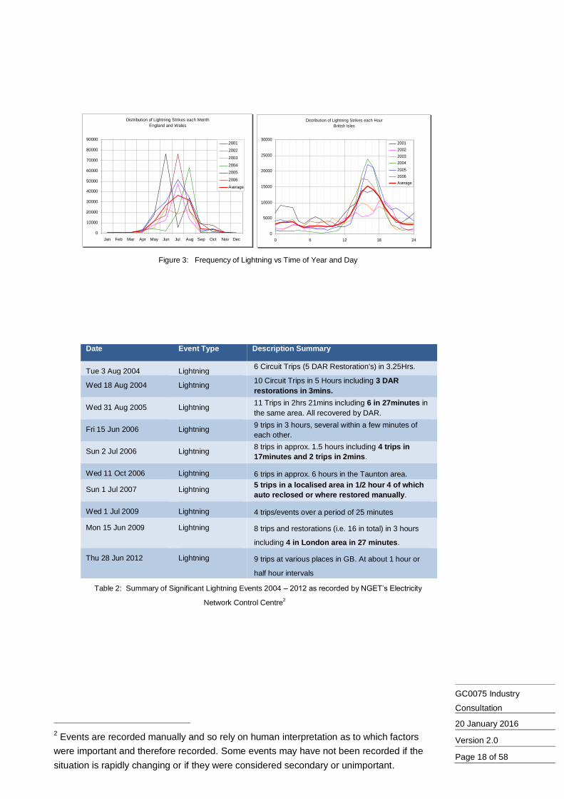
Although lightning strikes could take place at any time, the frequency 6.6.1distributions shown in Figure 3 suggest that the risk of a lightning strike taking place is higher during summer and in the afternoon. This correlates with the control room reports of significant lightning events (see Table 2).
The number of lightning strikes affecting a specific location varies from 6.6.2year to year as shown in Figure 4. This suggests that there is no correlation between the geographical location and the likelihood of a lightning strike taking place.
Over a specific period of time during a lightning storm, lightning strikes 6.6.3tend to be concentrated over specific areas. As the length of the specific period increases, the area affected increases. This is illustrated by Figure 5 which shows the location of individual lightning strikes that took place during 4 different days in June and August 2013.
1 The period 2001 to 2006 was chosen as the data is relatively recent, readily available
and in an appropriate format.
GC0075 Industry
Consultation
20 January 2016
Version 2.0
Page 18 of 58
Figure 3: Frequency of Lightning vs Time of Year and Day
Date Event Type Description Summary
Tue 3 Aug 2004 Lightning 6 Circuit Trips (5 DAR Restoration's) in 3.25Hrs.
Wed 18 Aug 2004 Lightning 10 Circuit Trips in 5 Hours including 3 DAR
restorations in 3mins.
Wed 31 Aug 2005 Lightning 11 Trips in 2hrs 21mins including 6 in 27minutes in
the same area. All recovered by DAR.
Fri 15 Jun 2006 Lightning 9 trips in 3 hours, several within a few minutes of
each other.
Sun 2 Jul 2006 Lightning 8 trips in approx. 1.5 hours including 4 trips in
17minutes and 2 trips in 2mins.
Wed 11 Oct 2006 Lightning 6 trips in approx. 6 hours in the Taunton area.
Sun 1 Jul 2007 Lightning 5 trips in a localised area in 1/2 hour 4 of which
auto reclosed or where restored manually.
Wed 1 Jul 2009 Lightning 4 trips/events over a period of 25 minutes
Mon 15 Jun 2009 Lightning 8 trips and restorations (i.e. 16 in total) in 3 hours
including 4 in London area in 27 minutes.
Thu 28 Jun 2012 Lightning 9 trips at various places in GB. At about 1 hour or
half hour intervals
Table 2: Summary of Significant Lightning Events 2004 – 2012 as recorded by NGET’s Electricity
Network Control Centre2
2 Events are recorded manually and so rely on human interpretation as to which factors
were important and therefore recorded. Some events may have not been recorded if the
situation is rapidly changing or if they were considered secondary or unimportant.
Distribution of Lightning Strikes each Month
England and Wales
0
10000
20000
30000
40000
50000
60000
70000
80000
90000
Jan Feb Mar Apr May Jun Jul Aug Sep Oct Nov Dec
2001
2002
2003
2004
2005
2006
Average
Distribution of Lightning Strikes each Hour
British Isles
0
5000
10000
15000
20000
25000
30000
0 6 12 18 24
2001
2002
2003
2004
2005
2006
Average

GC0075 Industry
Consultation
20 January 2016
Version 2.0
Page 19 of 58
Figure 4: Frequency of Lightning vs Location 2001 – 2006
Lightning Density 2001
All Year
2200-2300
2100-2200
2000-2100
1900-2000
1800-1900
1700-1800
1600-1700
1500-1600
1400-1500
1300-1400
1200-1300
1100-1200
1000-1100
900-1000
800-900
700-800
600-700
500-600
400-500
300-400
200-300
100-200
0-100
0
10000
20000
30000
40000
50000
60000
70000
10000 20000 30000 40000 50000 60000
Lightning Density 2002
All Year
2300-2400
2200-2300
2100-2200
2000-2100
1900-2000
1800-1900
1700-1800
1600-1700
1500-1600
1400-1500
1300-1400
1200-1300
1100-1200
1000-1100
900-1000
800-900
700-800
600-700
500-600
400-500
300-400
200-300
100-200
0-100
0
10000
20000
30000
40000
50000
60000
70000
10000 20000 30000 40000 50000 60000
Lightning Density 2003
All Year
800-900
700-800
600-700
500-600
400-500
300-400
200-300
100-200
0-100
0
10000
20000
30000
40000
50000
60000
70000
10000 20000 30000 40000 50000 60000
Lightning Density 2004
All Year
1800-1900
1700-1800
1600-1700
1500-1600
1400-1500
1300-1400
1200-1300
1100-1200
1000-1100
900-1000
800-900
700-800
600-700
500-600
400-500
300-400
200-300
100-200
0-100
0
10000
20000
30000
40000
50000
60000
70000
10000 20000 30000 40000 50000 60000
Lightning Density 2005
All Year
1900-2000
1800-1900
1700-1800
1600-1700
1500-1600
1400-1500
1300-1400
1200-1300
1100-1200
1000-1100
900-1000
800-900
700-800
600-700
500-600
400-500
300-400
200-300
100-200
0-100
0
10000
20000
30000
40000
50000
60000
70000
10000 20000 30000 40000 50000 60000
Lightning Density 2006
All Year
1900-2000
1800-1900
1700-1800
1600-1700
1500-1600
1400-1500
1300-1400
1200-1300
1100-1200
1000-1100
900-1000
800-900
700-800
600-700
500-600
400-500
300-400
200-300
100-200
0-100
0
10000
20000
30000
40000
50000
60000
70000
10000 20000 30000 40000 50000 60000

GC0075 Industry
Consultation
20 January 2016
Version 2.0
Page 20 of 58
Figure 5: Location of Lightning Strikes for Specific Hours of the Day on 8 June 2003, 10 August 2003, 22
June 2003 and 11 August 2003
Winter Storm Data
Transmission Licensees maintain logs of significant events, e.g. faults, that affected 6.7the transmission system over several decades. These logs contain information about the type, location, time, consequences of an event as well as the actions that were taken following such event. This includes both manual and machine recorded data. Prior to 1997 only paper records exist
Table 3 provides a summary of a sample of the significant events that resulted from 6.8adverse weather conditions. The information indicates that during severe weather conditions, the National Electricity Transmission System may be subjected to a series of events that take place sequentially within a short time period of each other.
Lightning strikes on 8 June 2003
0
10000
20000
30000
40000
50000
60000
70000
10000 20000 30000 40000 50000 60000
03:00 to 10:30
12:25 to 13:20
13:20 to 14:00
14:00 to 14:30
14:30 to 15:00
15:00 to 15:30
15:30 to 16:00
16:00 to 16:30
16:30 to 17:00
17:00 to 17:30
17:30 to 19:00
Lightning strikes on 10 August 2003
0
10000
20000
30000
40000
50000
60000
70000
10000 20000 30000 40000 50000 60000
06:30 to 08:00
08:00 - 08:30
08:30 - 09:00
09:00 to 09:30
09:30 to 10:00
10:00 to 10:30
10:30 to 11:30
11:30 to 13:00
13:00 to 14:00
14:040 to 15:00
15:00 to 16:30
16:30 to 18:00
18:00 to 20:00
20:00 to 24:00
Lightning strikes on 22June 2003
0
10000
20000
30000
40000
50000
60000
70000
10000 20000 30000 40000 50000 60000
00:30 to 05:30
05:30 - 06:30
06:30 - 07:15
07:17 - 07:45
07:45 to 08:15
08:15 to 10:00
10:00 to 15:00
15:00 to 15:20
15:20 to 15:40
15:40 to 16:00
16:00 to 17:00
17:00 to 24:00
Lightning strikes on 11 August 2003
0
10000
20000
30000
40000
50000
60000
70000
10000 20000 30000 40000 50000 60000
00:00 to 07:30
07:30 to 08:20
08:20 to 09:00
09:00 to 09:30
09:30 to 10:00
10:00 to 10:30
10:30 to 11:00
11:30 to 11:30
11:30 to 12:00
12:00 to 17:00

GC0075 Industry
Consultation
20 January 2016
Version 2.0
Page 21 of 58
Date Event Type Description Summary
Burns Day Storm 1990 Storm 261 trips 80 faulted circuits in 24hours.
Wed Thur 24/25 Dec
1997
Storm 33 circuits tripped in 5 Hours
Sat 26 Dec 1998 High Winds Approx. 20 trips, including 4 DAR restorations on
same line in 4mins.
Tue 27 Feb 2001 Snow & High
Winds
Multiple trips on Scot. Interconnector. 600MW
generation lost.
Sat 8 Jan 2005 Gales 32 faults on the NG System including 6 in 18, 7 in
21, 5 in 22 and 5 in 24mins, most of which were
restored by DAR
Thur 18 Jan 2007 137 Protection
Operations
51 DAR Sequences – 3 Conductor Failures resulting
in permanent loss of circuits. A further 14 trips in 4
hours including sequences of 4 trips in 40mins, 4
trips in 8mins, and 3 trips in 10mins. Most restored
by DAR.
Tue 3 Jan 2012 Severe Weather Over 50 Circuit Trips listed including event log.
Thur 5 Dec 2013 High Winds Multiple Circuit Trips – 5 Circuits left of service,
10MW of customer disconnection.
Mon 23 Dec 2013 High Winds Details approximately 17 circuit trips.
Table 3: Summary of data for some significant Winter Weather Events
The logs recorded by Transmission Licensees during three storms were extracted 6.9and analysed. The three storms are:
Scotland – 5 December 2013
Scotland – 3 January 2012
England – 23 and 24 December 2013
A summary of the data related to the three storms is shown in Table 4. The Scottish 6.10data shows event sequences of 67 events over a period of 3 hours. During this time 5 event clusters occurred where the cluster length was greater than or equal to 4 events with an average elapsed time between events of about 22 seconds.
The significant difference between the events recorded during the two storms in 6.11Scotland and that recorded during the storm in England arises from the difference in resolution between logging equipment in England and Wales, with a resolution of 1 minute, and the more modern one in Scotland, with a resolution of 1 second.
Scotland Scotland England
5/12/2013 3/1/2012
23/12/2013 24/12/2013
Clusters of events where each event in the cluster occurs within one minute from the preceding event
Total number of events that took place during the storm 41 67 20
The time form the first event till the last event (Hours) 4 3 4.5
Average time between each two successive events (minutes) 5.85 2.69 13.50
Minimum time between each two successive events (seconds) 11 4 60
Clusters of events where each event in the cluster occurs within one minute from the preceding
event
Number of clusters 8 14 1
Maximum number of events in a cluster 4 5 2
Clusters of events that comprised at least 4 events and each event in the cluster occurs within one minute from the preceding event
Number of clusters 4 5 0
Average Duration (seconds) 79 66.4 N/A
Table 4: Summary of event data for three storms considered

GC0075 Industry
Consultation
20 January 2016
Version 2.0
Page 22 of 58
For each of the three storms individually and for the combined set of date, the time 6.12difference, tdiff between each two consecutive events was calculated. Then, for each value of tdiff, the number of instances when an event took place within tdiff seconds of the previous event was counted. The resulting values were then added to determine, for each value of tdiff, the number of instances when an event took place within a period that is greater than or equal to tdiff. These values were then divided by the total number of events recorded during each storm and plotted in Figure 6.
Figure 6 provides an estimate on how likely a specific hybrid STATCOM/SVC would 6.13be able to provide a timely response to an event that took place during any of the three storms. For example, a hybrid STATCOM/SVC that could only respond to one event within 100 seconds would have been able to respond to only 62% of the events that took place in Scotland on the 5
th of December 2013 and to only 48% of
the events that took place in Scotland on the 3rd
of January 2012.
Figure 6: Probability of time difference between two successive events during a storm being greater than a
specific value
When a fault occurs on an HV line, the protection system opens the breakers at 6.14each end of the line to clear the fault. The breakers will then remain open for a period of time to allow ionized gas to blow away and/or arc deposits to fall away. This period is termed the ‘Dead Time’ and it typically ranges from 3seconds to 20seconds. After the Dead Time, DAR will automatically reclose the circuit breakers and restores the line back into service. In order to ensure that sustained faults do not result in repeated breaker operation, a fault detected in the time period immediately after the restoration of the line into service will cause the breakers to re-open and remain locked out. This time period, termed the ‘Reclaim Time,’ is typically in the range of 3s to 4s and is necessary to allow the insulation medium in the breaker (Oil / SF6) time to recover. However, a fault that re-occurs after the Reclaim Time will not lock out the circuit breaker and will allow DAR to restore the line after another Dead Time. Faults that repeatedly recur after the Reclaim Time, e.g. a series of lightning strikes, would require an operator intervention to switch DAR off and prevent the restoration of the line.
Sustained faults that are likely to cause breakers to lock out after the first DAR 6.15action include metal ladders left on conductors or closed earth switches. Faults that are likely to be cleared during the Dead Time include lightning strikes hitting a line; storms, high winds, or ice loading causing conductors to clash together; and debris, e.g. a polythene sheet, caught on a line.
Hybrid Performance verses Event Coverage
0.0%
20.0%
40.0%
60.0%
80.0%
100.0%
120.0%
1 10 100 1000
Hybrid switch repeat specification (seconds)
% e
ve
nts
(a
bilit
y t
o r
es
po
nd
)
Scotland 05-12-13Scotland 03-01-12England 24-12-13All
t (seconds)
Pro
ba
bili
ty o
f t d
iff≥
t (%
)

GC0075 Industry
Consultation
20 January 2016
Version 2.0
Page 23 of 58
Switching lines in and out redirects real and reactive power flows and may result in 6.16loss of generation, both of which can result in voltage fluctuations requiring response from voltage control systems.
As a series of lightning strikes hit some overhead lines within an area, or as a storm 6.17causes conductors of some overhead lines to clash, the affected circuits will be tripped by protection relays then restored by DAR action. Such sequence of events will result in series of changes of the transmission system topology, a series of changes in active and reactive power flow over different transmission circuits, and series of voltage step changes at different substations. Power Park Modules, including any hybrid STATCOM/SVC element, are expected to respond to these voltage step changes in accordance with the Grid Code.
Even if the sequence of lightning strikes or conductor clashing events affect the 6.18same transmission circuit(s), a series of circuit trip In such case, a series of on a specific line or surrounding lines can result in multiple DAR events. As these events are unlikely to occur during the reclaim period this can result in multiple responses from voltage control systems as the post fault power flows are redirected then restored.
Response of a Power Park Module to a Sequence of Events
In order to illustrate the impact of a sequence of events that affect the transmission 6.19system and the effect of using DAR on the reactive power output of a Power Park Module, a typical section of the National Electricity Transmission System, shown in Figure 7, was considered. It was assumed that four lightning strikes hit the same circuit. The second and third strikes were assumed to take place after the expiry of the Reclaim Time of DAR and hence did not result in DAR being blocked. The fourth lightning strike, on the other hand, was assumed to take place during the Reclaim Time and hence results in DAR being blocked. Protection was assumed to clear the fault after a 140ms from fault inception.
It was assumed that the Power Park Module connected to Substation C, prior to any 6.20fault, is operating at unity power factor. This Power Park Module was assumed to respond to voltage step changes that result from the sequence of events under consideration in accordance with the minimum Grid Code requirements. That is, it will start responding within 200ms from the voltage step change; it will provide 90% of the change in reactive power output after 1s; and will reach the steady state operating point after 5seconds. The Power Park Module was assumed to be capable of repeating the response for multiple voltage step changes.
DAR Operation
A
B
X X
X X
Fault Applied adjacent to
Substation A
CXX
XX Renewable
Generator
X
Low voltage seen across all parts of
the Network
Hybrid SVC or
STATCOMV
Q
Multiple lightning strikes or conductor clashing on a specific line or surrounding lines can result in multiple DAR events.
These events are unlikely to occur during the reclaim period this can result in multiple responses from voltage control system, as the post fault power flows are redirected then restored.
Figure 7: DAR Operation
As this sequence of events takes place, the voltage at substation C and the reactive 6.21power output of the Power Park Module connected to this substation will follow a pattern similar to the ones illustrated by Figure 8.
As the lightning strike hits the overhead line, a flashover will take place 6.21.1between the affected conductor and earth. This will result in a voltage drop at substation C. The actual value of voltage will depend on the network parameters and the location of the flashover.
As the affected circuit is tripped after 140ms, the voltage at substation C will 6.21.2increase again. However, due to the change in active and reactive power

GC0075 Industry
Consultation
20 January 2016
Version 2.0
Page 24 of 58
flows and the loss of the faulted circuit, it is likely that the voltage at substation C will be less than the pre-fault voltage.
In response to this, the Power Park Module will start injecting reactive power 6.21.3into the system. This will slightly increase the voltage at Substation C. However, the voltage will still be below its pre-fault level.
As DAR successfully restores the circuit and the pre-fault system 6.21.4configuration, and as the Power Park Module is injecting reactive power into the system, the voltage will increase above its pre-fault levels.
The Power Park Module will respond to this increase in voltage by 6.21.5decreasing the reactive power injected into the system. This will eventually restore the voltage at substation C to its pre-fault level and the reactive power output of the Power Park Module to zero.
Subsequent lightning strikes that take place after the DAR Reclaim Time 6.21.6result in the response described in Paragraph 6.21.1 to Paragraph 6.21.5 taking place.
As the final lightning strikes hits the overhead prior to the DAR Reclaim 6.21.7Time, the response described in Paragraph 6.21.1 to Paragraph 6.21.3 will take place but no further change will happen as the affected circuit remains out of service.
<1s<1s
Timing Diagram Volts at Substation D & Q Hybrid Injection vs Time
Q Response at C
NOTE: Diagram not to Scale
140ms
Target Volts
<1s
<1s
140ms140ms
>15s >15s
<1s <1s
DARTime
DARTime
DARTime
ReclaimTime
ReclaimTime
ReclaimTime
Low Volts0.9pu
High Volts
140ms<1s
0.95 PF Lag90%10%Unity PF
Fault occursFault clearedQ response starts90% of Response
<200ms
90% of responseQ response starts <0.2sLine back in service
<1s>15s
Start of next sequence
Volts at C
Figure 8: DAR Timing
Case Studies
The studies included in this consultation were first presented during the workshop in 6.22September 2013 are based on the contracted position on that date. The studies were referred to during subsequent Workgroup meetings.
The MW and MVAr rating of Users’ equipment are based on the contracted 6.23background and the Users’ Week24 submissions. Users’ plant data and dynamic models, other than MW and MVAr ratings, were replaced by generic data and models that meet the minimum Grid Code requirements. The output of the simulations reflect what could be expected to happen on the Transmission System however it does not completely reflect the actual performance of Users’ equipment.

GC0075 Industry
Consultation
20 January 2016
Version 2.0
Page 25 of 58
Implications of a sequence of recurring faults
This study demonstrates the effect of a sequence of recurring faults on one circuit 6.24on the reactive power output of a Power Park Module connected to a nearby substation.
The fault considered affects the three ended Spalding North/Bicker Fen/Walpol 6.25circuit (A65Y, A660 and A65W). The reactive Power Park Module considered is the 150MW windfarm contracted to connect to Mumby substation. Pre-fault conditions on the relevant section of the network are shown in Figure 9. Post-fault conditions on the same part of the network are shown in Figure 10.
Spalding North, Bicker Fen, Walpole Circuit Trip / DAR Operation
Before the circuit trip (A65W A65Y and A660) the Wind Farm at Mumby has both 150MVA Power Park Modules connected producing 2 x 93MW and 2 x -3.6MVAr
Circuit in Service
Widerview of relatednetwork
Figure 9: Spalding North, Bicker Fen & Walpole Study
Multiple DAR’s on this circuit alone, would require multiple operations of the Hybrid SVC / STATCOM capacitor and reactor switches.
Post Line Trip / Pre restoration
Figure 10:Spalding North, Bicker Fen & Walpole Study after Trip
Prior to the fault, the Power Park Module was injecting 3.6MVAr into the system. 6.26Following the fault taking place and fault clearance, the steady state reactive power output of the Power Park Module increases to 44.9MVAr. As DAR restores the circuit, the steady state reactive power output of the Power Park Module drops back to its pre-fault value of 3.6MVAr. As the fault recurs, the same response is expected to take place.
This study case demonstrates that recurrent faults may result in recurrent large 6.27swings in the reactive power output of Power Park Modules. This was 83.7% of the

GC0075 Industry
Consultation
20 January 2016
Version 2.0
Page 26 of 58
minimum reactive capability the Power Park Module considered in the case study is expected to have.
Implications of a sequence of faults affecting different circuits
This study demonstrates the effect of a sequence of faults on different circuits within 6.28the same part of the network on the reactive power output of a Power Park Module connected within the same part of the network.
The faults considered affect he circuits B38G, B38C, B389 and B38H in the Saltend 6.29area. Each fault results in protection tripping the affected circuit then followed by DAR restoring the circuit into service. The Power Park Module considered is rated a 380MW Power Park Module connected at Hedon. The relevant section of the network is shown in Figure 11.
The reactive power output of the Power Park Module following each event is shown 6.30in Table 5.
Figure 11: Saltend/Hedon multiple trip study
Event Post event reactive power injected to
the system (MVAr)
Pre-fault conditions -31.00
B38G trips -63.16
DAR on B38G -31.00
B38H trips +47.9
DAR on B38H -31.00
B389 trips -68.42
DAR on B389 -31.00
B38C trips -60.05
DAR on B38C -31.00
B389 & B38H trip +72.20
DAR on B389 & B38H -31.00
Table 5: Changes in the reactive power output of Power Park Modules at Hedon
The results shown in Table 6 suggest that for a series of events that take place 6.31within the same part of the network, a Power Park Module would experience a series of voltage step changes that, when responded to, would result in large changes in the reactive power output of the Power Park Module.

GC0075 Industry
Consultation
20 January 2016
Version 2.0
Page 27 of 58
Implications of post event restrictions on reactive capability of Power Park Modules
This study demonstrates the implications of a restriction on the reactive capability of 6.32Power Park Modules on the system performance and the ability to recover following a fault.
The background conditions assume that Synchronous Generating Units on the 6.33South East cost, i.e. Dungeness A and Shoreham, are not running and high output of windfarms connected, or contracted to connect, at Bolney, Cleve Hill, amd Canterbury North. The event considered is a double circuit fault on the Kemsley Cleve Hill/Kemsley Canturrbury North double circuit overhead line. The network diagram for the South East coast and the surrounding area is shown in Figure 12.
Situation Before Double Circuit Fault fromKemsley to South Coast – All voltages within 2.5%
Rampion
London Array
Thanet
Figure 12: South Coast Study
The following assumptions were made. 6.34
As the fault occurs, all the Power Park Modules are able to respond to 6.34.1voltage changes in accordance to the Grid Code requirements.
During the several minutes following responding to a disturbance and the 6.34.2removal of this disturbance, the reactive capability of Power Park Modules is restricted to 33% of its original value. Following this recovery period, the reactive capability of the Power Park Module is fully available.
The fault recurs prior to the expiry of the recovery period. 6.34.3
Power Park Modules will not be able to ride through voltage dips beyond 6.34.4that defined within CC.6.3.15
Figure 13 shows the expected change in voltage levels at four different substations 6.35during and after the double circuit fault. In this case, the system was able to reach the post fault steady state operating point within few seconds of fault clearance. As the affected circuits were restored and pre-fault system conditions re-established, Voltage levels returned back to their pre-fault values.

GC0075 Industry
Consultation
20 January 2016
Version 2.0
Page 28 of 58
0
0.2
0.4
0.6
0.8
1
1.2
0 2 4 6 8 10 12
pu
Vo
lts
(@
40
0k
V S
ub
sta
tio
ns
)
Time (seconds)
Substation Voltage vs Time
CANT4\CANT4 MC1A u, Magnitude in p.u. SELL4\SELL4 M1 u, Magnitude in p.u.
BRLE4\BRLE4 M1 u, Magnitude in p.u. EXET4\EXET4 M1 u, Magnitude in p.u.
Double Circuit Fault
Operator Intervention / Restoration
In this study it is assumed full reactive reserves are available from the three Wind Farms in the localised area (London Array, Rampion and Thanet). Lightning causes a double circuit fault and drop in volts. Adequate voltage support leads to a restorable situation through DAR or intervention from the operators in time scales which are long enough for operations to act if necessary.
Figure 13: South Coast Study with Full Reactive Reserve
Figure 14 shows the expected change in voltage levels at the same substations as 6.36the fault recurs within few seconds from the first fault. As Power Park Modules are only able to provide 33% of the reactive power output provided during the first fault, voltage levels at Sellindge and Canturbury North will drop below 85%. As the voltage dip is larger than that covered by the fault ride through requirements of the Gird Code, Power Park Modules will start tripping. In this case, two stages of load shedding were necessary to bring voltage levels within acceptable limits.
0
0.2
0.4
0.6
0.8
1
1.2
0 2 4 6 8 10 12
pu
Vo
lts
(@
40
0k
V S
ub
sta
tio
ns
)
Time (seconds)
Substation Voltage vs Time
CANT4\CANT4 MC1A u, Magnitude in p.u. SELL4\SELL4 M1 u, Magnitude in p.u.
BRLE4\BRLE4 M1 u, Magnitude in p.u. EXET4\EXET4 M1 u, Magnitude in p.u.
Loss of generation
~500MW Load Loss
~1GW Load Loss
Volts Below 0.85pu
Double Circuit Fault
In this study it is assumed ligthning has resulted in only depleted reactive reserves being available from the three
Wind Farms in the localised area (London Array, Rampion and Thanet).
Lightning causes a double circuit fault and drop in volts. Inadequate voltage support leads to cascade tripping of generation and loss of 1.5GW of load in timescales which are too
short for the operators to attempt intervention.
Figure 14: South Coast Study with Limited Reactive Reserve
The results suggest that restrictions on the reactive capability of Power Park 6.37Modules could undermine the System Operator’s ability to secure the system against credible events, e.g. a double circuit fault.

GC0075 Industry
Consultation
20 January 2016
Version 2.0
Page 29 of 58
Development of the Requirements
The Workgroup, with both Transmission Licensees objectives and Transmission 6.38System Users objectives in mind, and subject to the technical limitations on equipment available in the market, discussed what would be an adequate set of requirements that Power Park Modules need to meet in order to ensure that the Transmission System is able to recover after being affected by a sequence of events that take place over a short period of time and with very short time between each to successive events. The discussions were informed by the storm data, the lightning strike data, and information provided by manufacturers and Users.
The Workgroup agreed that, following responding to an event, a maximum of 15 6.39seconds should be allowed for Power Park Modules prior being required to be ready to respond to a subsequent event. The 15 seconds was specified based on the following factors:
A wide range of switchgear with spring re-charge time of 15 seconds or less 6.39.1is available in the market.
The 15 seconds interval is consistent with DAR timescales. 6.39.2
A Power Park Module that is able to respond to an event every 15 seconds 6.39.3would be able to respond to 96% of the events that arise during a winter storm.
The Workgroup proposed that the number of events a Power Park Module should be 6.40required to respond to over any 5 minutes period would be limited to 5 events. This number, based on the data provided in Table 5, guarantees that Power Park Module would be available to respond to the majority, if not all, of the events that may take place during a storm. This requirement allows some time for the capacitor discharge circuits to cool down between sequences of events whilst guaranteeing, on average, a close-open-close event every minute.
This requirement intends to specify the capability of switchgear to switch individual 6.41units back into service within a short time period from switching them out of service. Hence, the Workgroup agreed to define the event as a change of reactive power output from its maximum leading value to its maximum lagging value then back to its maximum leading value or from its maximum lagging value to its maximum leading value then back to its maximum lagging value. This is to ensure that all switchgear in a hybrid STATCOM/SVC unit is capable of repeatedly responding to disturbances.
The Workgroup proposed that the number of events a Power Park Module should be 6.42required to respond to over a day is limited to 25 events. Afterwards, Users would be able to lock any switching operations on their reactive compensation plant, in order to reduce wear and tear. This locking could take place automatically or manually following an alarm. In both cases, Users would be required to notify NGET in accordance with BC2.5.3.2 and BC2.6.1 of the Grid Code.
This requirement is introduced to allow a User to restrict the operation of a particular 6.43mechanical switch after 25 switching on operations in any 24 hours. For example, successive switching in and out of a mechanically switched capacitor element in a hybrid STATCOM/SVC for 25 times should be sufficient to allow the User to block further switching operations until the 24 hour period has passed. Hence, the Workgroup agreed to define the event as a change of reactive power output from its maximum leading value to its maximum lagging value then back to its maximum leading value or from its maximum lagging value to its maximum leading value then back to its maximum lagging value.
The Workgroup discussed that specifying a cap on the annual number of events the 6.44Power Park Module is expected to respond to however the idea was dismissed as this is driven by the number of faults that take place which varies from year to year. Fault statistics are provided in Annex 6 for information.
Equipment must be capable of responding to the three examples in Table 6 as 6.45described by the proposed CC.A.7.2.3.2. These detail the fastest sequences expected and one quick random sequence.

GC0075 Industry
Consultation
20 January 2016
Version 2.0
Page 30 of 58
Event Example 1 (secs)
(Shortest Time)
Example 2 (secs)
(Evenly Spaced)
Example 3 (secs)
(Random)
1 0 0 0
2 15 60 16
3 30 120 40
4 45 180 63
5 60 240 111
6 300 300 243
7 315 360 301
8 330 420 355
9 345 480 376
10 360 540 466
11 600 600 626
12 615 660 644
13 630 720 698
14 645 780 895
15 660 840 945
16 900 900 1019
17 915 960 1118
18 930 1020 1219
19 945 1080 1294
20 960 1140 1320
21 1200 1200 1356
22 1215 1260 1372
23 1230 1320 1470
24 1245 1380 1585
25 1260 1440 1621
Table 6: Event Sequences
Consistency of the Requirements with the European Network Codes
The two relevant European Network Codes are Requirements for Generators (RfG) 6.46and HVDC code. RfG applies to AC connected Power Park Modules. The HVDC code, on the other hand, applies to DC connected Power Park Modules. As the requirements are broadly aligned, reference in the paragraphs below has been made only to RfG.
The Workgroup discussed the consistency between the potential Grid Code 6.47requirements described in Paragraphs 6.38 to 6.45 and European Code Requirements for Generators (RfG) that Generating Units all over Europe are required to meet.
RfG Article 21 (3) (d), extract below, details the requirements that are relevant to 6.48STATCOMs and SVCs. Item (iv) of this Article, highlighted, and in particular the phrase underlined, is the section that may interact with the repeatability criteria proposed by the workgroup. This interpretation of this Item was debated by workgroup members.
With regard to reactive power control modes:
(i) the power park module shall be capable of providing reactive power automatically by either voltage control mode, reactive power control mode or power factor control mode;
(ii) for the purposes of voltage control mode, the power park module shall be capable of contributing to voltage control at the connection point by provision of reactive power exchange with the network with

GC0075 Industry
Consultation
20 January 2016
Version 2.0
Page 31 of 58
a setpoint voltage covering at least 0.95 to 1.05 pu in steps no greater than 0.01 pu, with a slope having a range of at least 2 to 7 % in steps no greater than 0.5 %. The reactive power output shall be zero when the grid voltage value at the connection point equals the voltage setpoint;
(iii) the setpoint may be operated with or without a deadband selectable in a range from zero to +-5 % of nominal network voltage in steps no greater than 0.5 %;
(iv) following a step change in voltage, the power park module shall be capable of achieving 90 % of the change in reactive power output within a time t1 to be specified by the relevant system operator in the range of 1 to 5 seconds, and must settle at the value specified by the operating slope within a time t2 to be specified by the relevant system operator in the range of 5 to 60 seconds, with a steady-state reactive tolerance no greater than 5 % of the maximum reactive power. The relevant system operator shall specify the time specifications;
(v) for the purpose of reactive power control mode3…
(vi) for the purpose of power factor control mode4…
(vii) the relevant system operator, in coordination with the relevant TSO and with the power park module owner, shall specify which of the above three reactive power control mode options and associated setpoints is to apply, and what further equipment is needed to make the adjustment of the relevant setpoint operable remotely;
Potential interpretations of RfG Article 21 (3)(d)(a) Item (iv), in relation to 6.49repeatability, are:
a Power Park Module should be capable of responding to a step change in 6.49.1voltage at any time even prior to reaching a steady state point;
a Power Park Module should be capable of responding to a step change in 6.49.2voltage at any time once it has reached its steady state operating point;
RfG was never intended to specify repeatability and is therefore irrelevant. 6.49.3
NGET favoured the first interpretation as it provides the System Operator with more 6.50flexibility than the other two options. Manufacturers and developers, on the other hand, favoured the third interpretation due to concerns over the frequent switching operations that might be required if either of the first two options were to be adopted, the consequent rise in maintenance cost and reduction in the life time of mechanical switches due to ware.
However, as the storm data indicated that a recovery time of 15seconds is sufficient 6.51to ensure that about 96% of events have been responded to and that 25 events/day is sufficient, the workgroup agreed that adopting either of the first two interpretations would result in unnecessary investment. Consequently, the workgroup agreed that RfG Article 21 (3)(d)(a) Item (iv) was not intended to specify repeatability.
Assessment of Option and Cost Benefit Analysis
The workgroup identified a set of solutions that could be used to ensure that when 6.52the majority of Generating Units connected to one area of the transmission system being Power Park Modules; and following a sequence of events that affect this area over a very short period, e.g. a minute or two, and with only seconds separating each two successive events; the system is able to recover to an acceptable operating point. These solutions are:
3 Paragraph not detailed as reactive power control mode is not required by the Grid Code.
4 Paragraph not detailed as power factor control mode is not required by the Grid Code.

GC0075 Industry
Consultation
20 January 2016
Version 2.0
Page 32 of 58
removing the requirements that Power Park Modules have reactive 6.52.1capability and voltage control capability such that this equipment is provided by Transmission Licensees;
Use of High Speed Auto Reclose instead of Delayed Auto Reclose; 6.52.2
Restricting Users from using hybrid STATCOM/SVC solutions to meet the 6.52.3reactive capability requirements and the voltage control requirement; and.
Placing technically feasible and economically justifiable requirements on 6.52.4Users in relation to their Power Park Modules such that they have the ability to meet the requirement using a hybrid STATCOM/SVC if they wish to.
Transmission Licensees provide reactive compensation
This option includes modifying the Grid Code to relieve the Users from meeting 6.53reactive capability requirements and voltage control requirements that are currently applicable to Power Park Modules. This will result in a shortage in reactive capability and voltage control options on the transmission system. Transmission Licensees would be required to invest in reactive compensation plant in order to replace this deficit
Transmission Licensees, in this case, will have the flexibility to optimise the size and 6.54location of reactive compensation which, theoretically, could drive the overall cost of reactive compensation equipment down. They will also have the flexibility to procure equipment with additional the capabilities, e.g. Power Oscillation Damping, if there is a need case.
However the workgroup noted that the requirement for reactive compensation is 6.55usually driven by active power flow and by the need to ensure that post-fault voltage levels remain within the limits specified in the Grid Code and the NETS SQSS. In practice, this means that it is very likely that there will be a need case to provide reactive compensation at the Grid Entry Point with a very limited scope for optimisation.
Where it is required to provide some dynamic reactive compensation at the Grid 6.56Entry Point, it is generally more economic and efficient to require Users to provide this range for two reasons:
A User will be able to take into account the inherent dynamic reactive 6.56.1capability available within their Power Park Modules. This will allow reducing the capacity of any reactive compensation plant without any implications on the reactive capability range available at the Grid Entry Point.
A User will have the ability to connect their reactive compensation 6.56.2equipment at the LV or MV side of their transformer whereas a Transmission Licensee will have to invest in an additional bay, switchgear, and transformer.
In all cases, it is likely that a Generator will need some dynamic reactive 6.57compensation in order to be able to manage voltage levels within the Power Park Module. Therefore any reduction or removal of the requirements would only eliminate the need case for the mechanically switched elements of a hybrid STATCOM/SVC and will only result in a minor saving in costs.
The figures in Table 7 show typical cost that different parties would incur to provide 6.58±30MVAr of dynamic reactive power compensation.
Table 7: Cost of Dynamic Reactive Compensation provided by different parties
Reactive Power Provider Cost
Offshore Transmission Licensee (Hybrid STATCOM) £2,450,535.
Offshore Transmission Licensee (Full STATCOM) £4,105,750
Onshore Power Park Module £1,225,268
Onshore Transmission Licensee £3,765,000

GC0075 Industry
Consultation
20 January 2016
Version 2.0
Page 33 of 58
Notes:
For an Onshore Power Park Module it is assumed that 15MVAr capability 6.58.1
would be available from Power Park Units and that the remaining 15MVAr would be provided by a STATCOM. For other cases, it was assumed that the full capability was provided by a STATCOM
Electricity Ten Year Statement indicate that, for NGET, the cost of a 50MVAr 6.58.2STATCOM ranges from £4.86M to £5.94M, the cost of a 100MVAr STATCOM ranges from £14.7M to £17.8M for a 100MVAr, and the cost of a 100MVAr SVC ranges from £9.5M to £11.7M. These figures were used to calculate an average cost/MVAr which was then used to estimate the cost of 30MVAr provided by an Onshore Transmission Licensee.
Similar data was provided by Users and Manufacturers in order to estimate 6.58.3the cost of reactive compensation provided by other parties.
The cost of a 100MVAr Capacitor ranges from £5.8M to £7.2M and that of a 6.58.4100MVAr reactor ranges from £3.7M to £4.5M. In order to replace a 100MVAr STATCOM or SVC with fixed shunt compensation it would be necessary to install both elements. That indicates that the use of fixed shunt compensation would typically provide 7.5-15.5% cost saving compared to STATCOM/SVC solutions.
Use of High Speed Auto Reclose
The use of High Speed Auto Reclose (HSAR allows the restoration of transmission 6.59circuits that were tripped following a fault within timescales that are quicker than that associated with DAR. This will result in pre-fault conditions being re-established before a Power Park Module responds to the initial voltage step change associated with the tripping of the faulted circuit. In other terms, Power Park Modules are less likely to be required to respond to a sequence of voltage step changes that take place within few seconds from each other.
HSAR is frequently used by other European Transmission System Operators. 6.60However, only one transmission circuit on the National Electricity Transmission System, in Scotland, is equipped with HSAR.
The cost of replacing DAR by HSAR comprises two main components. These are: 6.61
Switchgear control scheme. This value is estimated to be £500k/scheme5. 6.61.1
The number of schemes required to cover each circuit depends on the level of redundancy required to ensure reliable operation of protection schemes.
The potential cost of replacing some of the old technology switchgear, e.g. 6.61.2air blast circuit breakers, by modern switchgear that is capable of meeting the new duty. The cost of replacing one circuit breaker (275-400kV) ranges from £1.1M-£4.0M
6.
The overall cost of replacing DAR by HSAR on one circuit depends is a function of: 6.62
The number of switchgear schemes required to cover each circuit such to 6.62.1ensure reliable operation of protection schemes.
5 Estimates provided by NGET. no published figures exist for the control scheme the TO
6 According to ETYS 275 & 400 kV AIS bays are £1.1M-£1.4M GIS are £2.8M-£3.0M and £3.3M-£4.0M for 275kV
and 400kV respectively

GC0075 Industry
Consultation
20 January 2016
Version 2.0
Page 34 of 58
The number of old technology circuit breakers that needs upgrading which 6.62.2would depend on how many ends the circuit has and the type of each of the existing circuit breaker.
For HSAR to have the desired effect, it has to be rolled out within a whole area 6.63rather than used in one or two circuits. That implies that implementing HSAR would result in significant additional costs.
Restricting the use of hybrid STATCOM/SVC solutions
This option would be achieved via specifying requirements, e.g. on repeatability, that 6.64hybrid STATCOM/SVC solutions could not meet. Consequently, Users will need to procure STATCOMs/SVCs that are capable of meeting the reactive range requirements as specified in CC.6.3.2 without using switched capacitors/reactors.
Users and Manufacturers, currently operating in GB, have indicated this would 6.65typically increase the STATCOM/SVC cost by about 35% to 40%.
Specifying additional requirements on Power Park Modules that could be met via hybrid STATCOM/SVC solutions
This option includes modifying the Grid Code to include specific requirements on 6.66Power Park Modules that could be met by hybrid STATCOM/SVC solutions.
As the cost will be largely affected by the requirements, the workgroup decided to 6.67specify a set of requirements that would satisfy the objectives of both Transmission Licensees and Transmission System Users and assess the impact of meeting such requirements on the costs.
The cost incurred to Hybrid STATCOM / SVC’s as a result of the proposed Grid 6.68Code change is detailed in the manufacturer’s survey in Annex 5. For most designs this cost is negligible when compared to the other options.
Based on data provided by manufacturers, hybrid solutions that utilise switched 6.69capacitors, when meeting the repeatability requirements, could incur costs due to changes to ancillary and/or control equipment. This increase is about 20% of the cost of the switched capacitor unit. This would be considered significant on small installations with requirements for this Grid Code performance. However,
The modification proposed affects Medium and Large Power Park 6.69.1Modules. These have a minimum rating of 50MW in England and Wales, 30MW in Southern Scotland and 10MW in Northern Scotland.
Looking at typical published costs / MW of an installed onshore wind farm 6.69.2(e.g. £800k/MW) the total impact on the cost of the smallest wind farm in Northern Scotland (i.e. 10MW) is 0.33% on the total cost.
The only solution considered, is from one supplier. Once a market has 6.69.3been created, there is the possibility that competition will emerge.
Whilst the percentage cost increase on the wind farm is small, any 6.69.4incremental cost will have an impact on profitability of a project, especially if not identified at the design stage.
Preferred Option
Having reviewed the different options and the cost implications of each option, the 6.70Workgroup concluded that the preferred option is to modify the Grid Code to incorporate the requirements described in Paragraphs 6.38 to 6.45 as this requirements provide enough assurance that Power Park Modules will be able to respond to the majority of events that may take place, are technically feasible, satisfy the objectives of both Transmission Licensees and Transmission System Users, are consistent with RfG , and are the most economic option.

GC0075 Industry
Consultation
20 January 2016
Version 2.0
Page 35 of 58
Fault Ride Through and Post Fault Voltage Recovery 7
Faults on the transmission system result in voltage dips that spread over a large 7.1section of the network. An example of this is shown in Figure 15 that shows the widespread and the level of voltage depression resulting from a three-phase solid short circuit at Walpole substation.
The way different plant connected to the transmission system respond to this 7.2voltage dip affects the system’s ability to recover once the fault is cleared. Loss of reactive power injection to the system during a voltage dips will increase the widespread, magnitude and duration of this voltage dip.
The magnitude and duration of the voltage dip affect the way different generation 7.3and reactive compensation plant respond and their ability to remain connected to the system. A voltage dip that exceeds that defined within CC.6.3.15 may result in the loss of generation plant and any reactive power support these plants could provide to the system. A large reduction in voltage will reduce the reactive power output of static shunt compensation equipment.
Figure 15: Voltage Depression and MSC Shutdown during Faults
The Workgroup discussed the instances where Users have procured Power Park 7.4Modules that were designed such that during faults and voltage dips, switched shunt compensation are switched off. NGET advised that these plants were originally designed to switch out capacitors once the voltage drops below 0.7pu. However, the Manufacturer has revised the settings such that the capacitor is not switched out unless the voltage drops below 0.4pu and is restored into service within 300ms.
The workgroup noted that, based on the map shown in Figure 5, a fault at Walpole 7.5would result in the disconnection of shunt capacitors in a Power Park Module connected as far as East Claydon, Canturbury North, and Humber Refinery if these capacitors are designed to trip at 0.7pu. This will exacerbate the voltage depression and may lead to further tripping of plants. If the voltage level at which capacitors are tripped is reduced from 0.7pu to 0.4pu, the risk would be reduced but not completely eliminated.
The Workgroup acknowledged that, from a System Operator point of view, it is 7.6desirable to ensure that no shunt capacitors are switched off during faults or voltage dips such that they are available to assist post fault voltage recovery. None of the Workgroup members has raised any concern that meeting such requirements would involve significant costs. This was confirmed by the Manufacturer Survey in Annex 5.
The Workgroup agreed that the Grid Code requirements on fault ride through should 7.7be revised to specify that switched reactive compensation equipment should not be switched in or out during the initial phase of a fault, typically 80 to 140ms. Once the

GC0075 Industry
Consultation
20 January 2016
Version 2.0
Page 36 of 58
fault is cleared, the initial voltage depression has passed and the voltage recovery phase is underway, equipment may then change the switch states to initiate the normal reactive response as defined by CC.A.7.2.2.5 and CC.A.7.2.3.1. It was proposed not to express this as an obligatory requirement as manufacturers may choose to provide the response using a variety of sources and may not need to initially change the switch state.

GC0075 Industry
Consultation
20 January 2016
Version 2.0
Page 37 of 58
Other Issues 8
Additional Clarification of Transient Voltage Control Requirements CC.A.7.2.3
With the aim to clarify the requirements, the Workgroup discussed potential changes 8.1to CC.A.7.2.3.1. The following aspects were considered
The workgroup discussed the significance of the use of the phrase“…for a 8.2sufficiently large step…” within CC.A.7.2.3.1(ii) instead of stating a specific value. The Workgroup agreed that this is because the step change required to produce a specific change of reactive power output is dependent on the droop setting. For example, a change from zero reactive power output to the maximum leading, or lagging, reactive power output would result from a 2% step change in voltage for a Power Park Module operating with 2% droop or a 7% step change in voltage for a Power Park Module operating with 7% droop. The Workgroup agreed that this does not require any further clarification to the requirements.
The requirement that Power Park Modules has to be able respond to a voltage step 8.3change such that it achieves 90% of the response within 1 second, CC.A.7.2.3.1 (ii) has been a subject for discussion between Users and NGET. The Workgroup noted that, in all instances, all parties agreed that the requirement apply for change from unity power factor to the maximum leading or maximum lagging reactive power output or vice versa. The Workgroup recommended that the Grid Code is modified to clarify this understanding.
The Workgroup also proposed to specify that, where the voltage step change 8.4requires the Power Park Module to change its reactive power output from its maximum leading value to its maximum lagging value or vice versa, 90% of the response should be achieved within 2 seconds.
The Workgroup proposed to revise CC.A.7.2.3.1 (iv) to allow Power Park Modules 2 8.5seconds from achieving 90% of the response until the peak to peak magnitude of any oscillations settle within 5% of the change in steady state reactive power.
Communications and other issues beyond switching
Developers and Manufacturers have raised concerns that repeatability issues may 8.6arise during the system integration phase of the projects, where equipment from different manufacturers is connected together to provide the necessary overall response.
To date Compliance Tests have only established repeatability issues relating to 8.7mechanically switched components. During discussions it was concluded that whilst it is unlikely that system integration issues would affect the repeatability, they cannot be entirely discounted.
Logged Data from Wind Farms
One User stated that: 8.8
The severity of voltage disturbance at the location of the installed equipment 8.8.1depends on the distance and network to the fault location or power system contingency. Therefore considerable care should be taken when making the assumption that described events i.e. due to lightning strikes, will lead to voltage events of sufficient magnitude as to require a switching response from hybrid STATCOM systems; and
Measured results at transmission and distribution connected Power Park 8.8.2Module indicate that over a period of two years there were no transient voltage events of sufficient magnitude to exhaust the Power Park Module voltage control capability and thus require a switching response from the installed hybrid STATCOM system.

GC0075 Industry
Consultation
20 January 2016
Version 2.0
Page 38 of 58
Cost Implications
Any design change incurs an associated cost for the engineering time and any 8.9testing, hardware modification etc. Furthermore there maybe additional cost implications which extend beyond the design phase if there are changes to the manufacturing process or materials used.
The Workgroup discussed cost implications arising from the modification proposed 8.10via the manufacturers’ survey, the output of which is included in Annex 5. This data was used to inform the Options Assessment and the Cost Benefit Analysis covered in Section 6 Paragraphs 6.52 to 6.69.
Compliance Testing
Compliance with the Grid Code is principally the responsibility of the User. To record 8.11compliance, National Grid asks for statements of compliance with the individual clauses of the Grid Code and these statements will be extended to reflect the new repeatability clauses. As part of this working group National Grid has stated that there is no general expectation of asking users as part of compliance testing to demonstrate long sequences of multiple reactive responses. However, a test of a single repeat response may be requested on new plant or in the event of evidence of noncompliance.

GC0075 Industry
Consultation
20 January 2016
Version 2.0
Page 39 of 58
Implementation Considerations 9
Retrospective application
The modifications proposed do not apply retrospectively. 9.1
When should new requirements apply from?
The new requirements will only apply on User Plant and Apparatus connected to the 9.2system on or after 1 December 2017.
Which generation should this apply to?
The modification proposed applies to all Power Park Modules, DC Converters, and 9.3OTSDUW parties.
Consistency with European Network Codes
With regard to RfG, unless identified as part of the implementation phase, the 9.4workgroup is taking the position that the Grid Code changes recommended in this document are consistent with RfG as RfG makes no specific recommendation on repeatability.
Development of the Legal Text
Changes proposed to the legal text of the Grid Code were developed over several 9.5iterations with the aim to address the concerns highlighted by all the Workgroup members. The modifications, detailed in Annex 3, include:
modification of CC.A.7.2.3.1 to clarify the requirements; 9.5.1
addition of CC.A.7.2.3.2 to specify the new requirements related to 9.5.2repeatability; and
modification of CC.6.3.15 to clarify the fault ride through requirements in 9.5.3relation to switched shunt compensation.

GC0075 Industry
Consultation
20 January 2016
Version 2.0
Page 40 of 58
Conclusions and Recommendations 10
The proposed draft legal text covered in Annex 3 of this report was developed over 10.1several iterations which were discussed amongst the workgroup. The initial proposal related solely to repeatability criteria whilst also requiring discrete compensation devices to remain connected during faults or voltage disturbances. The text has been later modified in response to comments from the Grid Code Review Panel.
These proposals were further updated to define a repeatability criteria based on a 10.2limit of 5 events in 2 minutes with no more than 25 events in any 24 hour period. In addition further clauses were added requiring Generators to notify NGET of a declared reduction in reactive capability following 25 events.
The final proposal (as per Annex 3 of this Consultation) was then developed which 10.3aims to address the Grid Code defects by clarifying the following:-
• The time frame required for a Power Park Module or Reactive Compensation equipment to transit from full lead to full lag or vice versa.
• Clarifications to the settling time following a disturbance • The addition of a repeatability criteria requiring 5 consecutive responses
in any five minute period, no more than 15 seconds apart. • A criteria which limits the maximum number of events (ie unity to 90% full
leading or unity to 90% full lagging) to a maximum of 25 events in any 24 hour period.
• Where the daily limit of 25 events is exceeded the requirement to inform NGET of the reduction in reactive capability.
• Amendments to the fault ride through requirements clarifying reactive compensation equipment and requirements preventing them from switching during a fault ride through sequence.
The performance requirements specified above are believed to be satisfactory for 10.4the immediate future and ensure that Power Park Modules are capable of adequately responding to voltage changes triggered by the majority of successive faults that may occur under severe weather conditions. However, there is a risk that the 15 second recovery time of Power Park Modules will not allow them to sufficiently respond to voltage fluctuations associated with dynamic modes of oscillation.
As the dynamic performance of the system is changing rapidly and radically, the 10.5voltage control methodology along with other aspects of the dynamic performance will need to be kept under review.
The workgroup believes the recommended option is consistent with RfG and meets 10.6the minimum needs of the Transmission System.
In a rapidly changing electricity system which is increasingly dependent on non-10.7synchronous generators for dynamic response: the proposed legal text guarantees equipment performance in planning and operational time scales, giving the operators confidence that equipment is able to respond within DAR timescales. It also clearly sets out procedures for limited availability.
Some parties felt the existing Grid Code requirements were ambiguous. The 10.8proposed change aims to ensure there is no ambiguity and the minimum requirement is clearly established allowing manufacturers and developers to compete on an equitable basis. Whilst most manufacturers and developers have sited some increases, others have indicated either no increase or marginal changes in cost. It also ensures NGET is not dependant on some generators exceeding the requirements to make up any shortfall elsewhere on the system.
Recommendations
National Grid recommends the implementation of the proposed changes to the Grid 10.9Code as expressed in the legal text I Annex 3 of this document.

GC0075 Industry
Consultation
20 January 2016
Version 2.0
Page 41 of 58
Assessment 11
Impact on the Grid Code
The modifications proposed to the Connection Conditions and the Balancing Code 11.1are detailed in Annex 3 - Proposed Legal Text of this report.
Impact on Grid Code Users
This modification impacts the Developers, Manufacturers and Owners of Power Park 11.2Modules, Offshore Transmission Networks, and HVDC Converters.
Impact on National Electricity Transmission System (NETS)
State estimators, system models, and modelling algorithms may need to be changed 11.3to reflect the new reactive power control methodology.
Impact on Greenhouse Gas emissions
None 11.4
Assessment against Grid Code Objectives
The Grid Code Objectives: 11.5
(i) to permit the development, maintenance and operation of an efficient, coordinated and economical system for the transmission of electricity;
The Proposal minimises operational risks and the planning required for severe events and has minimal impact on generators and manufacturers and provides clarity of the requirement.
(ii) to facilitate competition in the generation and supply of electricity (and without limiting the foregoing, to facilitate the national electricity transmission system being made available to persons authorised to supply or generate electricity on terms which neither prevent nor restrict competition in the supply or generation of electricity);
The proposal has minimal impact on generators and manufacturers. Hybrid devices will be able to be used with minimal impact on cost. Current timing requirements offer manufacturer’s the widest options of switch choices available whilst ensuring the majority of system events are covered.
(iii) subject to sub-paragraphs (i) and (ii), to promote the security and efficiency of the electricity generation, transmission and distribution systems in the national electricity transmission system operator area taken as a whole; and
The proposal minimises risks that might arise during severe weather conditions and, consequently, the costs and the burden required to ensure that the system rides through such events. It has minimal impact on generators and manufacturers and ensures the majority of events are covered.
(iv) to efficiently discharge the obligations imposed upon the licensee by this license and to comply with the Electricity Regulation and any relevant legally binding decisions of the European Commission and/or the Agency.
The proposals have no interaction with the relevant European Network Code, which in this case is the Requirement for Generators code.
Impact on core industry documents
This document contains proposals to change the GB Grid Code. Further 11.6consideration should be given with regard to the STC, which may require consequential changes to ensure alignment.
Impact on other industry documents
None 11.7

GC0075 Industry
Consultation
20 January 2016
Version 2.0
Page 42 of 58
Impact on Bilateral Agreements
None 11.8
Implementation
The Workgroup proposes that, should the proposals be taken forward, the proposed 11.9changes be implemented 10 business days after an Authority decision.

GC0075 Industry
Consultation
20 January 2016
Version 2.0
Page 43 of 58
Responding to this Consultation 12
Views are invited upon the proposals outlined in this consultation, which should be 12.1received by 17 February 2016 using the proforma provided.
Responses may be emailed to [email protected]. 12.2
The proposals set out in this consultation are intended to better meet the Grid Code 12.3Objectives. To achieve this, they are intended to facilitate efficient and economic connection arrangements whilst ensuring there is no impact on the safety and security of the transmission system, and no discernible impact on the visual disturbance to electricity consumers.
Responses are invited to the following questions: 12.4
(i) Do you support the proposed approach? Please clarify why.
(ii) Do you believe that GC0075 better facilitates the appropriate Grid Code objectives? If not, why do they fail to do so?
(iii) Do the proposed changes facilitate efficient connection and operation of new and/or existing Power Park Modules which utilise Hybrid STATCOMs / SVCs? If not, why do they fail to do so?
(iv) Do the proposed changes impose any additional material risks on the System Operator, e.g. reduced stability margins, reduced reactive capability margins, or difficulty in managing transmission system voltages? If yes, please highlight these risks.
(v) Do the proposed changes impose any additional material risks on Transmission Owners, e.g. additional investment that might be neither economic nor efficient? If yes, please highlight these risks.
(vi) Do the proposed changes adequately protect the interests of all Transmission System Users? If not, why do they fail to do so?
(vii) Are there further technical considerations to be taken into account? If yes, please highlight these technical considerations.
(viii) Is there any evidence that Users will be inappropriately or adversely affected by the changes proposed? If so, please provide details.
(ix) Do the modifications proposed strike an appropriate balance between the needs of Generators, Transmission Licensees, and other interested parties? If not, why do they fail to do so?
(x) Please provide any other comments you feel are relevant to the proposed change.
If you wish to submit a confidential response please note the following: 12.5
(i) Information provided in response to this consultation will be published on National Grid’s website unless the response is clearly marked “Private and Confidential”, we will contact you to establish the extent of the confidentiality. A response marked “Private and Confidential” will be disclosed to the Authority in full but, unless agreed otherwise, will not be shared with the Grid Code Review Panel or the industry and may therefore not influence the debate to the same extent as a non-confidential response.
Please note that an automatic confidentiality disclaimer generated by your IT 12.6System will not in itself mean that your response is treated as if it had been marked “Private and Confidential”.

GC0075 Industry
Consultation
20 January 2016
Version 2.0
Page 44 of 58
Annex 1 – Grid Code Issue Paper
Grid Code Review Panel
GC0075 Hybrid Static Compensators - Update
Date Raised: 20 Nov 2013
GCRP Ref: pp13/671
A Panel Paper by Graham Stein / Richard Ierna
National Grid
Summary
Power Park Module developers have been installing Hybrid STATCOM / SVC’s, which provide a portion (typically 50% to 75%) of their reactive capability from switched reactors and capacitors. Some of these devices have restrictions preventing repeated switching in a short period which can be seen as inconsistent with the concept of "continuously acting" control which is required by the Grid Code. Interested parties believe clarification is required of the Grid Code requirements on these devices and that it would be beneficial to form a Workgroup to develop proposals for clearer and more appropriate requirements on Hybrid STATCOM / SVC performance.
Users Impacted
High – None Identified
Medium – Owners and developers of Power Park Modules – reduced risk of non-compliance and more appropriate performance requirements.
Low – None Identified
Description & Background
During compliance testing of new Power Park Modules it emerged that some manufacturers had interpreted the various references in the Grid Code to continuous voltage control, as a single linear increase or decrease in reactive power. National Grid's interpretation of the Code was that voltage control should be continuously available and that the equipment in question had unacceptable delays before the performance could be repeated. Manufacturers have indicated that the current performance regarding delays in operation, are driven by the switch gear, capacitor discharge and associated controls.
In addition, some manufacturers switch out the capacitors during a fault which could also be interpreted as a non-compliance. With regard to switching out capacitors several manufacturers have indicated that this is due to customer requests to do so, or to prevent over-voltage issues occurring.
Manufactures have identified a benefit in reduced costs of Hybrid designs compared to supplying a fully rated STATCOM / SVC. National Grid is keen to ensure that any potential shortfall in voltage control does not adversely impact on system security, or necessitate additional investment in alternatives, by achieving adequate discrimination between voltage control actions and network actions such as Delayed Auto Reclose.
1 The Code Administrator will provide the paper reference following submission to National Grid.
National Grid convened a workshop on the 20th September 2013 to seek an up to date view from interested parties which was attended by representatives of equipment suppliers and generation developers. Developers provided feedback to indicate that inconsistency in interpretation of the current requirements continued to present a material risk to their projects. Manufacturers highlighted that different interpretations by different manufacturers meant that some parties could be

GC0075 Industry
Consultation
20 January 2016
Version 2.0
Page 45 of 58
disadvantaged.
Proposed Solution
As an alternative to developers purchasing a fully rated STATCOM or thyristor switched shunt elements, National Grid has asked whether manufactures can improve the switchgear, capacitor discharge and control performance, possibly removing the need for fast discharge of the capacitors, and ensure it is not necessary to disconnect the capacitors at higher short circuit voltages.
Developers and manufacturers have asked that National Grid review the benefits that faster and repeatable actions from static components provide to the system, and to clarify the requirement to generate maximum reactive current during a fault.
Workshop attendees expressed a strong desire for these questions to be addressed and proposals for changes to the Grid Code to be progressed by an appropriate workgroup.
Assessment against Grid Code Objectives
The improvement in performance proposed, aims to allow manufacturers, developers and generators to benefit from the cost reduction offered by Hybrid STATCOM / SVC’s whilst restoring some of the capability lost, thereby improving system security and operability.
Clarification of the Grid Code will minimise the financial risk, posed by non-compliance to developers and manufacturers. It will also minimise the risk of Transmission Licensees having to make up a shortfall in reactive capability with alternative sources.
We believe the proposed changes to the Grid Code better facilitate the Grid Code Objectives:
(i) to permit the development, maintenance and operation of an efficient, coordinated and economical system for the transmission of electricity;
The main cost saving offered by Hybrid STATCOM / SVC’s would be available provided their performance meets the minimum needs of the System.
(ii) to facilitate competition in the generation and supply of electricity (and without limiting the foregoing, to facilitate the national electricity transmission system being made available to persons authorised to supply or generate electricity on terms which neither prevent nor restrict competition in the supply or generation of electricity);
Transparency of requirement and clarification of the code creates a market in which all manufacturers, developers and generators are able to compete fairly without the burden of unnecessary risk.
(iii) subject to sub-paragraphs (i) and (ii), to promote the security and efficiency of the electricity generation, transmission and distribution systems in the national electricity transmission system operator area taken as a whole;
Clarity of the requirement and subsequent improvement in performance, such that most of the originally intended capability is restored, whilst allowing the use of Hybrid solutions provides, in our view, the best compromise between ensuring system security and efficiency of delivery.
(iv) to efficiently discharge the obligations imposed upon the licensee by this license and to comply with the Electricity Regulation and any relevant legally binding decisions of the European Commission and/or the Agency.
Future system security will be maintained assuming adequate improvement in performance can be achieved in a timely manner.
Impact & Assessment

GC0075 Industry
Consultation
20 January 2016
Version 2.0
Page 46 of 58
Impact on the National Electricity Transmission System (NETS)
Hybrid STATCOM/SVC performance as proposed would ensure security of supply
is maintained and will provide greater resilience with respect to voltage collapse.
Impact on Greenhouse Gas Emissions
None
Impact on core industry documents
The Grid Code will be modified to clarify the requirements on Hybrid STATCOM /
SVC’s.
Impact on other industry documents
There may be a need to review similar provisions in STC Section K.
Supporting Documentation
GC0075 Hybrid Statcom Draft WG ToRs.doc
Hybrid_STATCOM_SVC_Workshop_20_09_2013.pdf
Recommendation
The Grid Code Review Panel is invited to:
Progress this issue to a Workgroup with the aim of clarifying the Grid Code so that
the performance requirements of Hybrid STATCOM / SVC’s are defined
appropriately.
Document Guidance
This proforma is used to raise an issue at the Grid Code Review Panel, as well as providing an initial assessment. An issue can be anything that a party would like to raise and does not have to result in a modification to the Grid Code or creation of a Working Group.
Guidance has been provided in square brackets within the document but please contact National Grid, The Code Administrator, with any questions or queries about the proforma at [email protected].

47 of 58
Annex 2 – Terms of Reference
GC0028 CONSTANT TERMINAL VOLTAGE
GC0075 HYBRID STATIC COMPENSATOR
TERMS OF REFERENCE
Governance
1. The Hybrid Static Compensator Workgroup was established by Grid Code Review Panel (GCRP) at the [November 2013] GCRP meeting.
2. The Workgroup shall formally report to the GCRP.
Membership Membership
3. The Workgroup shall comprise a suitable and appropriate cross-section of experience and expertise from across the industry, which shall include:
Name Role Representing
Graham Stein Chair
Franklin Roderick Technical Secretary
Antony Johnson / Richard Ierna
National Grid Representative National Grid
Industry Representative [PPM Developers]
Industry Representative [Hybrid STATCOM Equipment
Manufacturers]
Industry Representative [Transmission Owners]
Authority Representative Ofgem
Observer
Meeting Administration
4. The frequency of Workgroup meetings shall be defined as necessary by the Workgroup chair to meet the scope and objectives of the work being undertaken at that time.
5. National Grid will provide technical secretary resource to the Workgroup and handle administrative arrangements such as venue, agenda and minutes.
6. The Workgroup will have a dedicated section on the National Grid website to enable information such as minutes, papers and presentations to be available to a wider audience.
Scope
7. The Workgroup shall consider and report on the following:
The performance of Hybrid Static Compensators and comparable
equipment with respect to repeatability and the supply of reactive current during a fault

48 of 58
The performance required from voltage control equipment within Power
Park Modules to control voltage on the networks in the steady state, during and after secured events, and in the event of a wider system disturbance.
Deliverables
8. The Workgroup will provide updates and a Workgroup Report to the
Grid Code Review Panel which will:
Detail the findings of the Workgroup;
Draft, prioritise and recommend changes to the Grid Code and associated
documents in order to implement the findings of the Workgroup; and
Highlight any consequential changes which are or may be required,
Timescales
9. It is anticipated that this Workgroup will provide an update to each GCRP meeting and present a Workgroup Report to the [Timetable to be discussed] GCRP meeting.
10. If for any reason the Workgroup is in existence for more than one year, there is a responsibility for the Workgroup to produce a yearly update report, including but not limited to; current progress, reasons for any
delays, next steps and likely conclusion dates.

49 of 58
Annex 3 - Proposed Legal Text
New text is shown in Red
Connection Conditions
CC.A.7.2.3 Transient Voltage Control CC.A.7.2.3.1 … …
… (ii) the response shall be such that, for a sufficiently large step, 90% of
the change in the Reactive Power output full reactive capability of the Onshore Non-Synchronous Generating Unit, Onshore DC Converter, OTSDUW Plant and Apparatus or Onshore Power Park Module, as required by CC.6.3.2 (or, if appropriate,
CC.A.7.2.2.6 or CC.A.7.2.2.7), will be produced achieved within
1 second, where the step is sufficiently large to require a change in the steady state Reactive Power output from zero
to its maximum leading value or maximum lagging value, as required by CC.6.3.2 (or, if appropriate, CC.A.7.2.2.6 or CC.A.7.2.2.7); and
2 seconds, for Plant and Apparatus installed on or after 1 December 2017, where the step is sufficiently large to require a change in the steady state Reactive Power output from its
maximum leading value to its maximum lagging value or vice versa.
…
(iv) the settling time shall be no greater than within 2 seconds from the application of the step change in voltage and achieving 90% of the response as defined in CC.A.7.2.3.1 (ii), the peak to peak magnitude of any oscillations shall be less than 5% of the change in steady state Reactive Power within this time.
… CC.A.7.2.3.2 An Onshore Non-Synchronous Generating Unit, Onshore DC
Converter, OTSDUW Plant and Apparatus or Onshore Power Park Module installed on or after 1 December 2017 shall be capable of
(i) changing its Reactive Power output from its maximum lagging value
to its maximum leading value, or vice versa, then reverting back to the initial level of Reactive Power output once every 15 seconds for
at least 5 times within any 5 minute period; and
(ii) changing its Reactive Power output from zero to its maximum leading value then reverting back to zero Reactive Power output at least 25 times within any 24 hour period and from zero to its maximum lagging value then reverting back to zero Reactive Power
output at least 25 times within any 24 hour period. Any subsequent restriction on reactive capability shall be notified to NGET in
accordance with BC2.5.3.2, and BC2.6.1.
In all cases, the response shall be in accordance to CC.A.7.2.3.1where the change in reactive power output is in response to an on-load step change in Onshore Grid Entry Point or Onshore User System Entry Point voltage, or in the case of OTSDUW Plant and Apparatus an on-load step change in Transmission Interface Point voltage.

50 of 58
CC.6.3.15 Fault Ride Through …
CC.6.3.15.1 Fault Ride through applicable to Generating Units, Power Park Modules and DC Converters and OTSDUW Plant and Apparatus
(a) Short circuit faults on the Onshore Transmission System (which may include an Interface Point) at Supergrid Voltage up to 140ms
in duration.
(i) Each Generating Unit, DC Converter, or Power Park Module and any constituent Power Park Unit thereof and OTSDUW Plant and Apparatus shall remain transiently stable and connected to the System without tripping of any Generating Unit, DC Converter or Power Park Module and / or any constituent Power Park Unit, and OTSDUW Plant and Apparatus, and, for Plant and Apparatus installed on or after
1 December 2017, reactive compensation equipment, for a close-up solid three-phase short circuit fault or any unbalanced short circuit fault on the Onshore Transmission System (including in respect of OTSDUW Plant and Apparatus, the Interface Point) operating at Supergrid Voltages for a total
fault clearance time of up to 140 ms. A solid three-phase or unbalanced earthed fault results in zero voltage on the faulted phase(s) at the point of fault. The duration of zero voltage is dependent on local Protection and circuit breaker operating
times. This duration and the fault clearance times will be specified in the Bilateral Agreement. Following fault clearance, recovery of the Supergrid Voltage on the Onshore Transmission System to 90% may take longer than 140ms as illustrated in Appendix 4A Figures CC.A.4A.1 (a) and (b). It should be noted that in the case of an Offshore Generating Unit, Offshore DC Converter or Offshore Power Park Module (including any Offshore Power Park Unit thereof) which is connected to an Offshore Transmission System which includes a Transmission DC Converter as part of that Offshore Transmission System, the Offshore Grid Entry Point voltage may not indicate the presence of a fault on the Onshore Transmission System. The fault will affect the level of Active Power that can be transferred to the Onshore Transmission System and therefore subject the Offshore Generating Unit, Offshore DC Converter or Offshore Power Park Module (including any Offshore Power Park Unit
thereof) to a load rejection.
(ii) Each Generating Unit, Power Park Module and OTSDUW
Plant and Apparatus, shall be designed such that upon both clearance of the fault on the Onshore Transmission System
as detailed in CC.6.3.15.1 (a) (i) and within 0.5 seconds of the restoration of the voltage at the Onshore Grid Entry Point (for Onshore Generating Units or Onshore Power Park Modules) or Interface Point (for Offshore Generating Units, Offshore Power Park Modules or OTSDUW Plant and Apparatus) to the minimum levels specified in CC.6.1.4 (or within 0.5 seconds of restoration of the voltage at the User System Entry Point to 90% of nominal or greater if Embedded), Active Power output or in the case of OTSDUW Plant and Apparatus, Active Power transfer capability, shall be restored to at least 90% of
the level available immediately before the fault. Once the Active Power output, or in the case of OTSDUW Plant and Apparatus, Active Power transfer capability, has been restored to the required level, Active Power oscillations shall
be acceptable provided that:
- the total Active Energy delivered during the
period of the oscillations is at least that which would have been delivered if the Active Power
was constant

51 of 58
- the oscillations are adequately damped
During the period of the fault as detailed in CC.6.3.15.1 (a) (i) for which the voltage at the Grid Entry Point (or Interface Point in the case of OTSDUW Plant and Apparatus) is outside the limits specified in CC.6.1.4, each Generating Unit or Power Park Module or OTSDUW Plant and Apparatus
shall generate maximum reactive current without exceeding the transient rating limit of the Generating Unit, OTSDUW Plant and Apparatus or Power Park Module and / or any constituent Power Park Unit or reactive compensation equipment. For Plant and Apparatus installed on or after 1 December 2017, switched reactive compensation equipment (such as mechanically switched capacitors and reactors) shall be controlled such that it is not switched in or out of service during the fault but may act to assist in post fault voltage recovery
…
CC.6.3.15.2 Fault Ride Through applicable to Offshore Generating Units at a Large Power Station, Offshore Power Park Modules at a Large Power Station and Offshore DC Converters at a Large Power Station who choose to meet the fault ride through requirements at the LV side of the Offshore Platform
(a) Requirements on Offshore Generating Units, Offshore Power
Park Modules and Offshore DC Converters to withstand voltage dips on the LV Side of the Offshore Platform for up to 140ms in duration as a result of faults and / or voltage dips on the Onshore Transmission System operating at Supergrid Voltage
(i) Each Offshore Generating Unit, Offshore DC Converter, or Offshore Power Park Module and any constituent Power Park Unit thereof shall remain transiently stable and connected to the System without tripping of any Offshore Generating Unit, or Offshore DC Converter or Offshore Power Park Module and / or any constituent Power Park Unit or, in case of Plant and Apparatus installed on or after 1 December 2017, reactive compensation equipment, for any balanced or unbalanced voltage dips on the LV Side of the Offshore Platform whose profile is anywhere on or above the
heavy black line shown in Figure 6. For the avoidance of doubt, the profile beyond 140ms in Figure 6 shows the minimum recovery in voltage that will be seen by the generator following clearance of the fault at 140ms. Appendix 4B and Figures CC.A.4B.2 (a) and (b) provide further illustration of the voltage recovery profile that may be seen. It should be noted that in the case of an Offshore Generating Unit, Offshore DC Converter or Offshore Power Park Module (including any Offshore Power Park Unit thereof) which is connected to an Offshore Transmission System which includes a Transmission DC Converter as part of that Offshore Transmission System, the Offshore Grid Entry Point voltage may not indicate the presence of a fault on the Onshore Transmission System. The voltage dip will affect the level of Active Power that can be transferred to the Onshore Transmission System and therefore subject the Offshore Generating Unit, Offshore DC Converter or Offshore Power Park Module (including any Offshore Power Park Unit thereof) to a load rejection.

52 of 58
Figure 6
V/VN is the ratio of the actual voltage on one or more phases at the LV Side of the Offshore Platform to the nominal voltage of the LV Side of the Offshore Platform.
(ii) Each Offshore Generating Unit, or Offshore Power Park
Module and any constituent Power Park Unit thereof shall provide Active Power output, during voltage dips on the LV Side of the Offshore Platform as described in Figure 6, at least in proportion to the retained voltage at the LV Side of the Offshore Platform except in the case of an Offshore Non-Synchronous Generating Unit or Offshore Power Park Module where there has been a reduction in the Intermittent Power Source in the time range in Figure 6 that restricts the Active Power output below this level and shall
generate maximum reactive current without exceeding the transient rating limits of the Offshore Generating Unit or Offshore Power Park Module and any constituent Power Park Unit or, in case of Plant and Apparatus installed on or after 1 December 2017, reactive compensation equipment. Once the Active Power output has been restored to the required level, Active Power oscillations shall be acceptable provided that:
- the total Active Energy delivered during the
period of the oscillations is at least that which would have been delivered if the Active Power
was constant
- the oscillations are adequately damped and;
(iii) Each Offshore DC Converter shall be designed to meet the Active Power recovery characteristics as specified in the Bilateral Agreement upon restoration of the voltage at the LV Side of the Offshore Platform.
(b) Requirements of Offshore Generating Units, Offshore Power Park Modules to withstand voltage dips on the LV Side of the Offshore Platform greater than 140ms in duration.
In addition to the requirements of CC.6.3.15.2. (a) each Offshore Generating Unit or Offshore Power Park Module and / or any constituent Power Park Unit, shall:
(i) remain transiently stable and connected to the System without
tripping of any Offshore Generating Unit or Offshore Power Park Module and / or any constituent Power Park Unit, for any balanced voltage dips on the LV side of the Offshore Platform and associated durations anywhere on or above the
heavy black line shown in Figure 7. Appendix 4B and Figures CC.A.4B.3. (a), (b) and (c) provide an explanation and illustrations of Figure 7. It should be noted that in the case of an Offshore Generating Unit, or Offshore Power Park Module (including any Offshore Power Park Unit thereof) which is connected to an Offshore Transmission System

53 of 58
which includes a Transmission DC Converter as part of that Offshore Transmission System, the Offshore Grid Entry Point voltage may not indicate the presence of a voltage dip on the Onshore Transmission System. The voltage dip will affect the level of Active Power that can be transferred to the Onshore Transmission System and therefore subject the Offshore Generating Unit, or Offshore Power Park Module (including any Offshore Power Park Unit thereof) to a load rejection.
Figure 7
(ii) provide Active Power output, during voltage dips on the LV Side of the Offshore Platform as described in Figure 7, at
least in proportion to the retained balanced or unbalanced voltage at the LV Side of the Offshore Platform except in the case of an Offshore Non-Synchronous Generating Unit or Offshore Power Park Module where there has been a reduction in the Intermittent Power Source in the time range in Figure 7 that restricts the Active Power output below this level and shall generate maximum reactive current (where the voltage at the Offshore Grid Entry Point is outside the limits
specified in CC.6.1.4) without exceeding the transient rating limits of the Offshore Generating Unit or Offshore Power Park Module and any constituent Power Park Unit or reactive compensation equipment. For Plant and Apparatus installed
on or after 1 December 2017, switched reactive compensation equipment (such as mechanically switched capacitors and reactors) shall be controlled such that it is not switched in or out of service during the fault but may act to assist in post fault voltage recovery; and,
…

54 of 58
Annex 4 – Register of Attendance
The table below details the Workshop (WS) and Workgroup (WG) attendance. Workgroup members were additionally invited to answer the following question:
Do the proposals address the Grid Code defects? Yes/No
Ad
dre
ss
es
Gri
d C
od
e
De
fec
t
20
/08
/20
13
15
/05
/20
14
07
/08
/20
14
22
/10
/20
14
26
/01
/20
15
27
/04
/20
15
Name Organisaton WS WG-1 WG-2 WG-3 WG-4 WG-5
Richard Ierna National Grid Y, Y, Y 1 1 1 1 1 1
Graham Stein National Grid Y, Y, Y 1 1
Athony Johnson National Grid Y, Y, Y 1 1 1 1 1
Razwan Pabat-StroeScottish Power Y, Y, Y 1 1 1 1 1
Sridhar Sahukari Dong Energy NO 1 1 1 1
Mustafa Kayikci TNEI 1
Lee Holdsworth RES Yes 1 1 1
Mike Lee Transmiss ion Investment 1
Mick Chowns RWE Yes 1 1 1
Isaac Gutierez Iberdrola/Scottish PowerYes 1 1 1
Rui Rui Iberdrola/Scottish Power 1 1
Damian Jackman SSE Generation 1 1 1
Peter Jones ABB 1
Anne Pales jo ABB 1
Al i reza Mousavi ABB 1
Phi l l ipe Maibach ABB 1
Simon VogelsangerABB 1
Fahd Hashiesh ABB 1 1
Al i reza Mousavi ABB 1 1
Matthias Gautschi ABB
Shafiu Ahmed Siemens Yes 1 1
Chingla i Mor Siemens 1
Ian Cunningham Alstom Grid 1
Vesa Oinonen Alstom Grid
Martin Lyster AMSC 1
John Diaz de Leon AMSC Yes 1 1 1 1 1
Steve Mortimer S&C Electric 1
Cl i fton El l i s S&C Electric 1 1 1
Mick Barlow S&C Electric 1 1 1 1 1 1
Laurent Poutra in Vizimax 1 1
Peter Thomas Nordex 1 1
Amir Dahresobh Nordex 1
Charles Creswel l Senvion UK 1 1 1 1 1
Nia l l Duncan Senvion UK 1
Sigrid Bol ik Senvion UK 1 1
Manufacturers (Hybrids & Switch Gear)
Manufacturers (Wind Turbines)
Transmiss ion Owners & Operators
Developers
OFTOs
Generators

55 of 58
Annex 5 – Manufacturers Survey
Various manufacturers were consulted throughout the discussions to ensure that the requirements proposed are technically feasible and do not impose significant costs on developers.
In addition, a questionnaire was sent to six manufacturers that offer hybrid STATCOM / SVC solutions requesting that they confirm whether they could offer solutions that meet the requirements proposed or not and provide estimates of any increase in costs that might result from these requirements. A summary of responses is given in Table 8.
Ma
nu
fac
ture
r
Co
mp
lia
nt
wit
h
ne
w r
ep
ea
tab
ilit
y
Re
qu
irem
en
t
% I
nc
reas
e i
n u
nit
co
st
if n
ot
co
mp
lia
nt
Av
aila
bilit
y
Co
mp
lia
nt
wit
h
ne
w F
RT
req
uir
em
en
t
% I
nc
reas
e i
n u
nit
co
st
if n
ot
co
mp
lia
nt
Av
aila
bilit
y
A Current design meets proposed change
0% Now Current design meets proposed change or Blocks at 0.4pu (Both Available Now)
0.5%
Now
B Current design meets
proposed change
0% Now Current design meets
proposed change
0% Now
C Current design meets proposed change
0% Now Current design meets proposed change
0% Now
D Proposed change is feasible
0% Now Current design meets
proposed change 0%
Now
E Proposed change is feasible
-13%
to
+7%7
12 Mths
Current design meets proposed change
0% Now
F Current design meets proposed change
0% Now No Answer - -
Table 8: Survey results
7 -13% to +7% depends on equipment rating. Clarification of the requirement has in this
case leads to cost decreases for some equipment ratings and increases for others.

56 of 58
Annex 6 – Fault Statistics
Annual fault records for the period from 1990 to 2002 are shown in the Table 9. This table aims to provide Users and manufacturers with an indication of the typical number and nature of faults that may take place over the course of a year. It also highlights the potential variability and difficulties associated with specifying an annual cap on the number of events a Power Park Module would be required to respond to.
Table 9: Annual Fault Figures 1990 to 2002

57 of 58
Annex 5 – Acronyms and Abbreviations
This section contains abbreviations and acronyms used in this document.
Acronym /
Abbreviation Description AC Alternating Current BC Balancing Code CB Circuit Breaker CC Connection Conditions CCS Carbon Capture and Storage cct Circuit CHP Combined Heat and Power CUSC Connection and Use of System Code DAR Delayed Auto Reclose DC Direct Current DFIG Doubly Fed Induction Generator EMF Electro Motive Force ENTSOe European Network of Transmission System Operators for Electricity ETYS Electricity Ten Year Statement HSAR High Speed Auto Reclose FES Future Energy Scenario FON Final Operational Notification FRT Fault Ride Through GB Great Britain GC Grid Code GCRP Grid Code Review Panel GW Giga Watts HCDC High Voltage Direct Current HV High Voltage KPI Key Performance Indicators kV kilo Volts LV Low Voltage M/C Machine MSC Mechanically Switched Capacitor Mths Months MVA Mega Volt Ampere’s – Apparent Power MVAr Mega Volt Ampere’s Reactive – Reactive Power MW Mega Watts NB Nota Bene - Note Well NETS National Electricity Transmission System NGET National Grid Electricity Transmission OEM Original Equipment Manufacturer OFGEM Office of Gas and Electricity Markets OFTO Offshore Transmission Owner OHL Overhead Line OTSDUW Offshore Transmission System Developer User Works P Real Power (i.e. MW) PF Power Factor Plc Public Limited Company POC Point of Connection POD Power Oscillation Damping PPM Power Park Modules pu Per Unit Q Reactive Power (i.e. MVAr’s) RfG Requirements for Generators SF6 Sulphur Hexafluoride SHETL Scottish Hydro Transmission Ltd. SQSS System Quality of Supply Standards STATCOM Static Compensator SO System Operator

58 of 58
STC System operator Transmission owner Code SSD Switched Shunt Device SVC Static VAr Compensator TF Transfer function TO Transmission Owner UK United Kingdom V Voltage VN Voltage Nominal (i.e. Nominal Volts) vs Verses VT Voltage Transformer WF Wind Farm WG Work Group