gdi+ programming in c# and vb - webnodefiles.shin-soaru.webnode.com/200000089-c242fc33a0... · gdi+...
TRANSCRIPT
GDI+ Programming in C# and VB .NET
NICK SYMMONDS
035front.fm Page i Saturday, May 25, 2002 3:26 PM

GDI+ Programming in C# and VB .NETCopyright © 2002 by Nick Symmonds
All rights reserved. No part of this work may be reproduced or transmitted in any form or by any means, electronic or mechanical, including photocopying, recording, or by any information storage or retrieval system, without the prior written permission of the copyright owner and the publisher.
ISBN (pbk): 1-59059-035-X
Printed and bound in the United States of America 12345678910
Trademarked names may appear in this book. Rather than use a trademark symbol with every occurrence of a trademarked name, we use the names only in an editorial fashion and to the benefit of the trademark owner, with no intention of infringement of the trademark.
Technical Reviewer: Adriano Baglioni
Editorial Directors: Dan Appleman, Peter Blackburn, Gary Cornell, Jason Gilmore, Karen Watterson, John Zukowski
Managing Editor: Grace Wong
Project Manager and Development Editor: Tracy Brown Collins
Copy Editor: Nicole LeClerc
Production Editor and Proofreader: Kari Brooks
Compositor: Susan Glinert Stevens
Artist and Cover Designer: Kurt Krames
Indexer: Valerie Perry
Manufacturing Manager: Tom Debolski
Marketing Manager: Stephanie Rodriguez
Distributed to the book trade in the United States by Springer-Verlag New York, Inc., 175 Fifth Avenue, New York, NY, 10010 and outside the United States by Springer-Verlag GmbH & Co. KG, Tiergartenstr. 17, 69112 Heidelberg, Germany.
In the United States, phone 1-800-SPRINGER, email [email protected], or visit http://www.springer-ny.com.
Outside the United States, fax +49 6221 345229, email [email protected], or visit http://www.springer.de.
For information on translations, please contact Apress directly at 2560 9th Street, Suite 219, Berkeley, CA 94710. Phone 510-549-5930, fax: 510-549-5939, email [email protected], or visit http://www.apress.com.
The information in this book is distributed on an “as is” basis, without warranty. Although every precaution has been taken in the preparation of this work, neither the author nor Apress shall have any liability to any person or entity with respect to any loss or damage caused or alleged to be caused directly or indirectly by the information contained in this work.
The source code for this book is available to readers at http://www.apress.com in the Downloads section.
035front.fm Page ii Wednesday, May 29, 2002 2:42 PM
165
CHAPTER 5
Advanced Graphics
Dolores breezed along the surface of her life like a flat stone forever skipping across smooth water, rippling reality sporadically but oblivious to it consis-
tently, until she finally lost momentum, sank, and due to an overdose of fluoride as a child which caused her to lie forever on the floor of her life
as useless as an appendix and as lonely as a five-hundred-pound barbell in a steroid-free fitness center.
—Linda Vernon, Newark, California (1990 Winner)
HELLO, AND WELCOME to Chapter 5.In Chapter 4 I took you through most of the System.Drawing namespace. The
majority of this namespace is devoted to the Graphics class and its members. This chapter delves a little deeper into some of the more esoteric aspects of pens and brushes. It also goes much deeper into drawing itself.
In this chapter, you will be introduced to some of the more complicated vector graphics drawing concepts, such as
• Matrix transforms
• Color blending
• Gradients
• Drawing and filling in shapes made from Graphics paths
While some of the classes in this chapter are from the System.Drawing namespace, most of the chapter is devoted to the System.Drawing.Drawing2D namespace.
More About Pens, Lines, and Brushes
Chapter 4 had quite a bit of information on pens and brushes. However, some of the Pen members are more than a little basic, so I decided to leave them to this chapter. The Pen members I’m referring to are as follows:
035c05.fm Page 165 Sunday, May 19, 2002 4:54 PM

Chapter 5
166
• Pen.LineJoin
• Pen.CustomEndCap
• Pen.CustomStartCap
Along with these Pen members, there are also a couple of other related classes:
• CustomLineCap
• AdjustableArrowCap
As you can probably guess, these methods, properties, and classes have to do with how the pen looks as it is drawing lines or other shapes. Let’s start with the LineJoin method.
Start a new project in either C# or VB. Size the form to be 400×400. Go into the code and type in the skeleton for the OnPaint method. The OnPaint method should be ingrained in your brain by now. It is without a doubt the most important method in any graphics program. Enter the code shown in Listing 5-1.
Listing 5-1a. Different LineJoin Methods in VB
Protected Overrides Sub OnPaint(ByVal e As PaintEventArgs)
Dim G As Graphics = e.Graphics
Dim PtsA As Point() = {New Point(10, 10), _
New Point(150, 150), _
New Point(400, 10)}
Dim PtsB As Point() = {New Point(10, 40), _
New Point(150, 180), _
New Point(400, 40)}
Dim PtsC As Point() = {New Point(10, 70), _
New Point(150, 210), _
New Point(400, 70)}
Dim PtsD As Point() = {New Point(10, 100), _
New Point(150, 240), _
New Point(400, 100)}
Dim P As Pen = New Pen(Color.Blue, 10)
NOTE Be sure to include the following namespaces in all your code for this chapter: System.Drawing and System.Drawing.Drawing2D.
035c05.fm Page 166 Sunday, May 19, 2002 4:54 PM
Advanced Graphics
167167
G.SmoothingMode = SmoothingMode.AntiAlias
P.LineJoin = LineJoin.Bevel
G.DrawLines(P, PtsA)
P.LineJoin = LineJoin.Miter
G.DrawLines(P, PtsB)
P.LineJoin = LineJoin.MiterClipped
G.DrawLines(P, PtsC)
P.LineJoin = LineJoin.Round
G.DrawLines(P, PtsD)
End Sub
Listing 5-1b. Different LineJoin Methods in C#
protected override void OnPaint ( PaintEventArgs e )
{
Graphics G = e.Graphics;
Point[] PtsA = { new Point(10, 10),
new Point(150, 150),
new Point(400, 10) };
Point[] PtsB = { new Point(10, 40),
new Point(150, 180),
new Point(400, 40) };
Point[] PtsC = { new Point(10, 70),
new Point(150, 210),
new Point(400, 70) };
Point[] PtsD = { new Point(10, 100),
new Point(150, 240),
new Point(400, 100) };
Pen P = new Pen(Color.Blue, 10);
G.SmoothingMode=SmoothingMode.AntiAlias;
P.LineJoin=LineJoin.Bevel;
G.DrawLines(P, PtsA);
P.LineJoin=LineJoin.Miter;
G.DrawLines(P, PtsB);
P.LineJoin=LineJoin.MiterClipped;
G.DrawLines(P, PtsC);
P.LineJoin=LineJoin.Round;
G.DrawLines(P, PtsD);
}
035c05.fm Page 167 Sunday, May 19, 2002 4:54 PM
Chapter 5
168
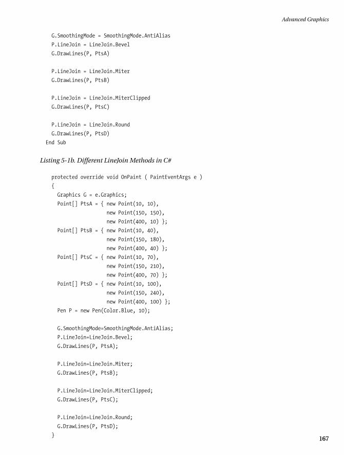
Here you’re making a set of points that describe line segments. You then set the smoothing mode to AntiAlias so you can see a straight line. Next, you draw lines that are connected according to the LineJoin enumeration.
There are four LineJoin enumerations:
• Bevel: Joins two lines with a bevel on the outside of the joint.
• Miter: Joins two lines with a miter joint. This bisects the angle of the two lines.
• MiterClipped: Joins two lines with a miter joint if the length of the miter exceeds the MiterLimit. Joins two lines with a bevel if the length of the miter is within the MiterLimit.
• Round: Joins two lines with a smooth, round corner.
The result of running the code in Listing 5-1 is shown in Figure 5-1.
Figure 5-1. Result of different corners joining two lines
Back in Chapter 4 I discussed several kinds of start and end caps that you can put on a line. These caps are far more interesting than the normal straight, boxed ends. Next, you will define your own start and end caps.
You define a custom cap using the CustomLineCap class. This class has four overloaded constructors as well as five properties. The constructors’ arguments are as follows:
035c05.fm Page 168 Sunday, May 19, 2002 4:54 PM
Advanced Graphics
169169
• GraphicsPath defines the fill. GraphicsPath defines the outline.
• GraphicsPath defines the fill. GraphicsPath defines the outline. LineCap defines the base of the custom cap.
• GraphicsPath defines the fill. GraphicsPath defines the outline. LineCap defines the base of the custom cap. Inset defines the distance between the line and the cap.
The properties of the CustomLineCap class basically make up the individual arguments of the constructors. They are as follows:
• BaseCap: The LineCap enumeration on which this cap is based.
• BaseInset: The distance between the end of the line and the cap.
• StrokeJoin: The LineJoin enumeration that determines how lines in the cap are joined.
• WidthScale: The scaling factor of the cap to the pen width.
Listing 5-2 shows an example of how to create a custom line caps. Start with a new project and do all the work in the OnPaint method.
Listing 5-2a. CustomLineCap Example in C#
protected override void OnPaint ( PaintEventArgs e )
{
Graphics G = e.Graphics;
Pen P = new Pen(Color.Blue, 1 );
Point[] Pts = { new Point( 10, 10 ),
new Point( 15, 10 ),
new Point( 20, 15 ),
new Point( 20, 20 ),
new Point( 15, 25 ),
new Point( 10, 25 ),
new Point( 5, 20 ),
new Point( 5, 15 ),
new Point( 10, 10 )};
GraphicsPath Path = new GraphicsPath();
Path.AddLines (Pts);
035c05.fm Page 169 Sunday, May 19, 2002 4:54 PM
Chapter 5
170
G.SmoothingMode=SmoothingMode.AntiAlias;
CustomLineCap Lc = new CustomLineCap( null, Path );
Lc.BaseInset=0;
Lc.WidthScale=1;
Lc.StrokeJoin=LineJoin.Miter;
P.CustomEndCap = Lc;
P.CustomStartCap=Lc;
G.DrawLine ( P, 50, 150, 200, 150 );
G.DrawLine ( P, 150, 50, 150, 200 );
Lc.Dispose();
Path.Dispose();
P.Dispose();
}
Listing 5-2b. CustomLineCap Example in VB
Protected Overrides Sub OnPaint(ByVal e As PaintEventArgs)
Dim G As Graphics = e.Graphics
Dim P As Pen = New Pen(Color.Blue, 1)
Dim Pts() As Point = {New Point(10, 10), _
New Point(15, 10), _
New Point(20, 15), _
New Point(20, 20), _
New Point(15, 25), _
New Point(10, 25), _
New Point(5, 20), _
New Point(5, 15), _
New Point(10, 10)}
Dim Path As GraphicsPath = New GraphicsPath()
Path.AddLines(Pts)
G.SmoothingMode = SmoothingMode.AntiAlias
Dim Lc As CustomLineCap = New CustomLineCap(Nothing, Path)
Lc.BaseInset = 0
Lc.WidthScale = 1
Lc.StrokeJoin = LineJoin.Miter
P.CustomEndCap = Lc
P.CustomStartCap = Lc
035c05.fm Page 170 Sunday, May 19, 2002 4:54 PM
Advanced Graphics
171171
G.DrawLine(P, 50, 150, 200, 150)
G.DrawLine(P, 150, 50, 150, 200)
Lc.Dispose()
Path.Dispose()
P.Dispose()
End Sub
Using the Hatch Brush
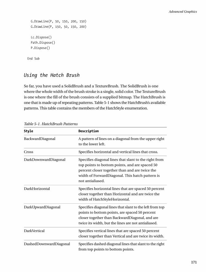
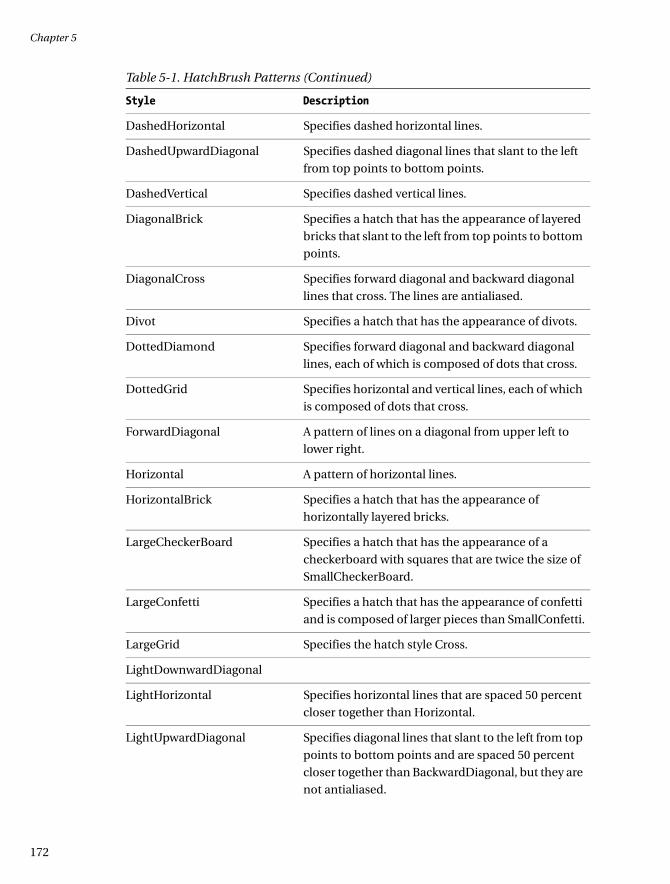
So far, you have used a SolidBrush and a TextureBrush. The SolidBrush is one where the whole width of the brush stroke is a single, solid color. The TextureBrush is one where the fill of the brush consists of a supplied bitmap. The HatchBrush is one that is made up of repeating patterns. Table 5-1 shows the HatchBrush’s available patterns. This table contains the members of the HatchStyle enumeration.
Table 5-1. HatchBrush Patterns
Style Description
BackwardDiagonal A pattern of lines on a diagonal from the upper right
to the lower left.
Cross Specifies horizontal and vertical lines that cross.
DarkDownwardDiagonal Specifies diagonal lines that slant to the right from
top points to bottom points, and are spaced 50
percent closer together than and are twice the
width of ForwardDiagonal. This hatch pattern is
not antialiased.
DarkHorizontal Specifies horizontal lines that are spaced 50 percent
closer together than Horizontal and are twice the
width of HatchStyleHorizontal.
DarkUpwardDiagonal Specifies diagonal lines that slant to the left from top
points to bottom points, are spaced 50 percent
closer together than BackwardDiagonal, and are
twice its width, but the lines are not antialiased.
DarkVertical Specifies vertical lines that are spaced 50 percent
closer together than Vertical and are twice its width.
DashedDownwardDiagonal Specifies dashed diagonal lines that slant to the right
from top points to bottom points.
035c05.fm Page 171 Sunday, May 19, 2002 4:54 PM
Chapter 5
172
DashedHorizontal Specifies dashed horizontal lines.
DashedUpwardDiagonal Specifies dashed diagonal lines that slant to the left
from top points to bottom points.
DashedVertical Specifies dashed vertical lines.
DiagonalBrick Specifies a hatch that has the appearance of layered
bricks that slant to the left from top points to bottom
points.
DiagonalCross Specifies forward diagonal and backward diagonal
lines that cross. The lines are antialiased.
Divot Specifies a hatch that has the appearance of divots.
DottedDiamond Specifies forward diagonal and backward diagonal
lines, each of which is composed of dots that cross.
DottedGrid Specifies horizontal and vertical lines, each of which
is composed of dots that cross.
ForwardDiagonal A pattern of lines on a diagonal from upper left to
lower right.
Horizontal A pattern of horizontal lines.
HorizontalBrick Specifies a hatch that has the appearance of
horizontally layered bricks.
LargeCheckerBoard Specifies a hatch that has the appearance of a
checkerboard with squares that are twice the size of
SmallCheckerBoard.
LargeConfetti Specifies a hatch that has the appearance of confetti
and is composed of larger pieces than SmallConfetti.
LargeGrid Specifies the hatch style Cross.
LightDownwardDiagonal
LightHorizontal Specifies horizontal lines that are spaced 50 percent
closer together than Horizontal.
LightUpwardDiagonal Specifies diagonal lines that slant to the left from top
points to bottom points and are spaced 50 percent
closer together than BackwardDiagonal, but they are
not antialiased.
Table 5-1. HatchBrush Patterns (Continued)
Style Description
035c05.fm Page 172 Sunday, May 19, 2002 4:54 PM

Advanced Graphics
173173
LightVertical Specifies vertical lines that are spaced 50 percent
closer together than Vertical.
Max Specifies the hatch style SolidDiamond.
Min Specifies the hatch style.
NarrowHorizontal Specifies horizontal lines that are spaced 75 percent
closer together than the hatch style Horizontal (or 25
percent closer together than LightHorizontal).
NarrowVertical Specifies vertical lines that are spaced 75 percent
closer together than the hatch style Vertical (or 25
percent closer together than LightVertical).
OutlinedDiamond Specifies forward diagonal and backward diagonal
lines that cross but are not antialiased.
Percent05 Specifies a 5 percent hatch. The ratio of foreground
color to background color is 5:100.
Percent10 Specifies a 10 percent hatch. The ratio of foreground
color to background color is 10:100.
Percent20 Specifies a 20 percent hatch. The ratio of foreground
color to background color is 20:100.
Percent25 Specifies a 25 percent hatch. The ratio of foreground
color to background color is 25:100.
Percent30 Specifies a 30 percent hatch. The ratio of foreground
color to background color is 30:100.
Percent40 Specifies a 40 percent hatch. The ratio of foreground
color to background color is 40:100.
Percent50 Specifies a 50 percent hatch. The ratio of foreground
color to background color is 50:100.
Percent60 Specifies a 60 percent hatch. The ratio of foreground
color to background color is 60:100.
Percent70 Specifies a 70 percent hatch. The ratio of foreground
color to background color is 70:100.
Percent75 Specifies a 75 percent hatch. The ratio of foreground
color to background color is 75:100.
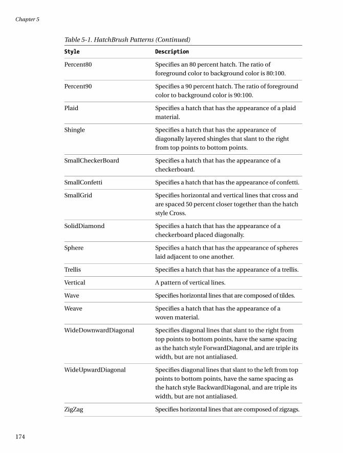
Table 5-1. HatchBrush Patterns (Continued)
Style Description
035c05.fm Page 173 Sunday, May 19, 2002 4:54 PM
Chapter 5
174
Percent80 Specifies an 80 percent hatch. The ratio of
foreground color to background color is 80:100.
Percent90 Specifies a 90 percent hatch. The ratio of foreground
color to background color is 90:100.
Plaid Specifies a hatch that has the appearance of a plaid
material.
Shingle Specifies a hatch that has the appearance of
diagonally layered shingles that slant to the right
from top points to bottom points.
SmallCheckerBoard Specifies a hatch that has the appearance of a
checkerboard.
SmallConfetti Specifies a hatch that has the appearance of confetti.
SmallGrid Specifies horizontal and vertical lines that cross and
are spaced 50 percent closer together than the hatch
style Cross.
SolidDiamond Specifies a hatch that has the appearance of a
checkerboard placed diagonally.
Sphere Specifies a hatch that has the appearance of spheres
laid adjacent to one another.
Trellis Specifies a hatch that has the appearance of a trellis.
Vertical A pattern of vertical lines.
Wave Specifies horizontal lines that are composed of tildes.
Weave Specifies a hatch that has the appearance of a
woven material.
WideDownwardDiagonal Specifies diagonal lines that slant to the right from
top points to bottom points, have the same spacing
as the hatch style ForwardDiagonal, and are triple its
width, but are not antialiased.
WideUpwardDiagonal Specifies diagonal lines that slant to the left from top
points to bottom points, have the same spacing as
the hatch style BackwardDiagonal, and are triple its
width, but are not antialiased.
ZigZag Specifies horizontal lines that are composed of zigzags.
Table 5-1. HatchBrush Patterns (Continued)
Style Description
035c05.fm Page 174 Sunday, May 19, 2002 4:54 PM
Advanced Graphics
175175
Listing 5-3 shows an OnPaint method that draws on the screen using a HatchBrush.
Listing 5-3a. HatchBrush in C#
protected override void OnPaint ( PaintEventArgs e )
{
HatchBrush h = new HatchBrush(HatchStyle.BackwardDiagonal,
Color.Black,
Color.Cyan);
Pen P = new Pen(h, 20);
e.Graphics.Clear(Color.AliceBlue);
e.Graphics.SmoothingMode = SmoothingMode.AntiAlias;
e.Graphics.DrawLine(P, 80, 90, 80, 200 );
e.Graphics.FillEllipse(h, 50, 50, 50, 30 );
P.Dispose();
h.Dispose();
}
Listing 5-3b. HatchBrush in VB
Protected Overrides Sub OnPaint(ByVal e As PaintEventArgs)
Dim h As HatchBrush = New HatchBrush(HatchStyle.BackwardDiagonal, _
Color.Black, _
Color.Cyan)
Dim P As Pen = New Pen(h, 20)
e.Graphics.Clear(Color.AliceBlue)
e.Graphics.SmoothingMode = SmoothingMode.AntiAlias
e.Graphics.DrawLine(P, 80, 90, 80, 200)
e.Graphics.FillEllipse(h, 50, 50, 50, 30)
P.Dispose()
h.Dispose()
End Sub
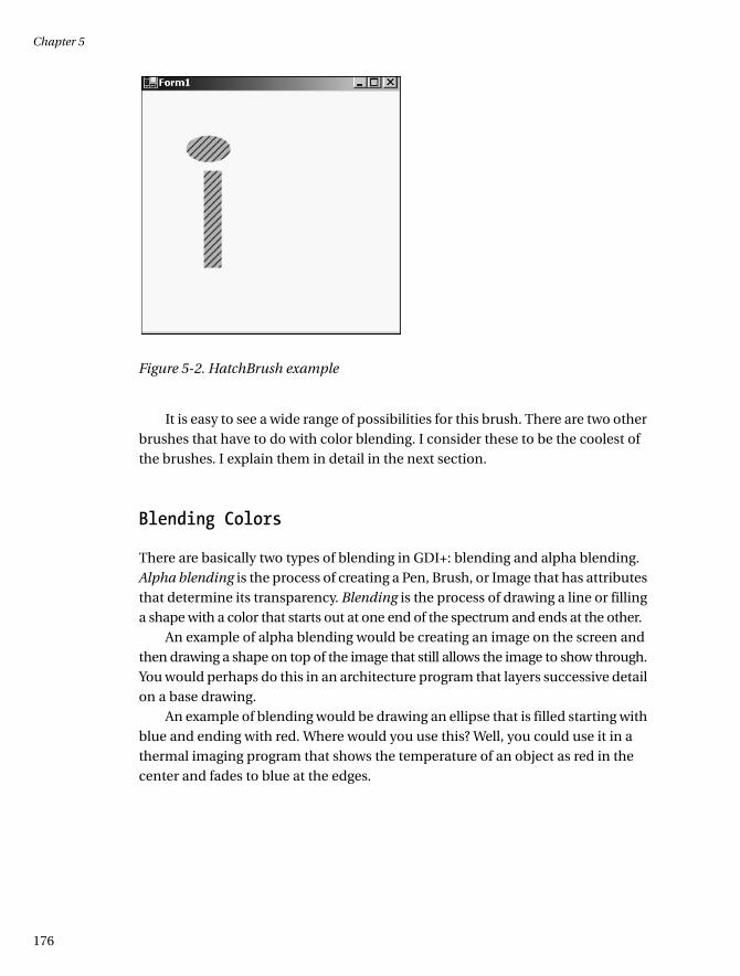
The result of this program is shown in Figure 5-2.
035c05.fm Page 175 Sunday, May 19, 2002 4:54 PM
Chapter 5
176
Figure 5-2. HatchBrush example
It is easy to see a wide range of possibilities for this brush. There are two other brushes that have to do with color blending. I consider these to be the coolest of the brushes. I explain them in detail in the next section.
Blending Colors
There are basically two types of blending in GDI+: blending and alpha blending. Alpha blending is the process of creating a Pen, Brush, or Image that has attributes that determine its transparency. Blending is the process of drawing a line or filling a shape with a color that starts out at one end of the spectrum and ends at the other.
An example of alpha blending would be creating an image on the screen and then drawing a shape on top of the image that still allows the image to show through. You would perhaps do this in an architecture program that layers successive detail on a base drawing.
An example of blending would be drawing an ellipse that is filled starting with blue and ending with red. Where would you use this? Well, you could use it in a thermal imaging program that shows the temperature of an object as red in the center and fades to blue at the edges.
035c05.fm Page 176 Sunday, May 19, 2002 4:54 PM

Advanced Graphics
177177
Alpha Blending
It is possible to create a brush that blends its color with that of the background. The same goes for a Pen or an Image. You will need to become familiar with the following terms and ideas before you can start using this feature effectively:
• Alpha factor
• Compositing mode
• Gamma correction
The alpha factor determines the transparency of the color. This is an 8-bit value that ranges from 0 to 255. Zero represents a fully transparent color and 255 represents a completely opaque color. So far in this book, all the colors you have used have had an alpha factor of 255; they have all been solid colors.
The compositing mode is slightly different from the alpha factor. It has to do with how images are blended in a transparent manner rather than single colors. The Graphics class has an enumeration called Graphics.CompositingMode. This enumeration has two values:
• CompositingMode.SourceCopy defines that the source image completely overwrites the background colors.
• CompositingMode.SourceOver defines that the source image is blended with the background image, depending on the alpha blending factor.
Often the compositing mode is used in conjunction with the alpha factor. The compositing mode is used as a switch to turn on or off the transparency of the source image.
The MSDN help for .NET defines gamma correction as describing the shape of the brightness transfer function for one or more stages in an imaging pipeline. What?! In English, gamma correction refers to the brightness of the image. Useful values can range from 0.1 to about 5.0, but normal values are between 1.0 and 2.2. A value of 1.0 is “standard.” The lower the gamma value, the brighter the image.
So now that you know some terms, how about an example? This example will not be as simple as previous ones. It includes the following aspects of a .NET program:
• A couple of controls with delegates assigned to the events
• Variables that are local to the class itself
035c05.fm Page 177 Sunday, May 19, 2002 4:54 PM
Chapter 5
178
• Initialization code for constituent controls
• Disposal of class-local objects
• Try-Finally block for handling disposal of local objects
Open a new Windows Forms project in either C# or VB. I called mine Blend. Place two horizontal scroll bars on the form. Call one AlphaScroll and call the other one GammaScroll. Do not worry about placement right now, as you will write code to place these scroll bars correctly.
Once you have placed the scroll bars on the screen, double-click each one to force the code wizard to generate the scroll delegate for you. You could change the name of the delegate, or even combine both into one, but for now just accept what the wizard made for you.
This example contains code that reads an image from the disk. I chose the color bars hatch image because it shows a multitude of distinct colors without
being fuzzy when expanded. I put this image in the root of my D: drive to make it easy to get to. You can find this image in the samples that come with .NET.
Listing 5-4 shows the code necessary for this example. I do not include the “Windows Form Designer generated code” section. Be sure to include the System.Drawing, System.Drawing.Drawing2D, and System.Drawing.Imaging namespaces.
Listing 5-4a. Alpha Blend, Compositing, and Gamma Correction Example in C#
using System;
using System.Drawing;
using System.Drawing.Imaging;
using System.Drawing.Drawing2D;
using System.Collections;
using System.ComponentModel;
using System.Windows.Forms;
using System.Data;
namespace Blend_c
{
NOTE It is, of course, entirely possible to write the code for all the examples in this book without adding references to namespaces. However, you would need to fully qualify every method and class, which can lead to overly verbose code and confusion.
035c05.fm Page 178 Sunday, May 19, 2002 4:54 PM

Advanced Graphics
179179
public class Form1 : System.Windows.Forms.Form
{
private System.Windows.Forms.HScrollBar AlphaScroll;
/// <summary>
/// Required designer variable.
/// </summary>
private System.ComponentModel.Container components = null;
private int AlphaFactor = 255;
private float GammaFactor = 1.0f;
private Rectangle R = new Rectangle(40, 20, 100, 100 );
private Image I = Image.FromFile("d:\\Colorbars.jpg");
private int ImWidth;
private int ImHeight;
private System.Windows.Forms.HScrollBar GammaScroll;
private ImageAttributes Ia = new ImageAttributes();
public Form1()
{
//
// Required for Windows Form Designer support
//
InitializeComponent();
AlphaScroll.Minimum = 20;
AlphaScroll.Maximum = 245;
AlphaScroll.SmallChange = 5;
AlphaScroll.LargeChange = 5;
AlphaScroll.Left = R.Left;
AlphaScroll.Width = R.Width;
AlphaScroll.Top = R.Bottom;
GammaScroll.Minimum=1;
GammaScroll.Maximum = 50;
GammaScroll.SmallChange=1;
GammaScroll.LargeChange=5;
GammaScroll.Left = R.Left;
GammaScroll.Top = R.Top - GammaScroll.Height;
GammaScroll.Width = R.Width;
ImWidth = I.Width;
ImHeight = I.Height;
035c05.fm Page 179 Sunday, May 19, 2002 4:54 PM
Chapter 5
180
AlphaScroll.Value = (AlphaScroll.Maximum-AlphaScroll.Minimum )/2;
GammaScroll.Value = (GammaScroll.Maximum-GammaScroll.Minimum )/2;
AlphaFactor = AlphaScroll.Value;
GammaFactor = (float)GammaScroll.Value / 10;
}
protected override void Dispose( bool disposing )
{
if( disposing )
{
if (components != null)
{
components.Dispose();
}
if ( I != null )
I.Dispose();
if ( Ia != null )
Ia.Dispose();
}
base.Dispose( disposing );
}
/// <summary>
/// The main entry point for the application.
/// </summary>
[STAThread]
static void Main()
{
Application.Run(new Form1());
}
private void Form1_Load(object sender, System.EventArgs e)
{
}
protected override void OnPaint(PaintEventArgs e)
{
AlphaBlend(e.Graphics);
base.OnPaint(e);
}
035c05.fm Page 180 Sunday, May 19, 2002 4:54 PM
Advanced Graphics
181181
private void AlphaBlend( Graphics G )
{
//AlphaFactor is variable depeneding upon scroll bars
Pen P = new Pen( Color.FromArgb (AlphaFactor, 200, 0, 100 ), 20);
Bitmap bmp = new Bitmap( 120, 120 );
Graphics G2 = Graphics.FromImage(bmp);
Brush B = new SolidBrush(Color.FromArgb( AlphaFactor, 50, 200, 50 ));
try
{
// Set the brightness while rendering image
Ia.SetGamma( GammaFactor );
G.DrawImage(I, R, 0, 0, ImWidth, ImHeight, GraphicsUnit.Pixel, Ia);
//Draw transparent line on top of image
G.DrawLine(P, 10, 100, 200, 100 );
// Draw inside the image contained in memory
G2.FillEllipse( B, 0, 0, 75, 75 );
G.DrawImage( I, new Rectangle(140, 140, 120, 120 ) );
G.CompositingQuality = CompositingQuality.GammaCorrected;
G.CompositingMode = CompositingMode.SourceOver;
G.DrawImage( bmp, new Rectangle( 150, 150, 150, 150 ) );
}
finally
{
if (bmp != null )
bmp.Dispose();
if ( G2 != null )
G2.Dispose();
if ( B != null )
B.Dispose();
if ( P != null )
P.Dispose();
}
}
private void AlphaScroll_Scroll(object sender,
System.Windows.Forms.ScrollEventArgs e)
{
AlphaFactor = AlphaScroll.Value;
this.Refresh();
}
035c05.fm Page 181 Sunday, May 19, 2002 4:54 PM
Chapter 5
182
private void GammaScroll_Scroll(object sender,
System.Windows.Forms.ScrollEventArgs e)
{
GammaFactor = (float)GammaScroll.Value / 10;
this.Refresh();
}
}
}
Listing 5-4b. Alpha Blend, Compositing, and Gamma Correction Example in VB
Option Strict On
Imports System.Drawing
Imports System.Drawing.Drawing2D
Imports System.Drawing.Imaging
Public Class Form1
Inherits System.Windows.Forms.Form
Private AlphaFactor As Int32 = 255
Private GammaFactor As Single = 1.0F
Private R As Rectangle = New Rectangle(40, 20, 100, 100)
Private I As Image = Image.FromFile("d:\\Colorbars.jpg")
Private ImWidth As Int32
Private ImHeight As Int32
Private Ia As ImageAttributes = New ImageAttributes()
#Region " Windows Form Designer generated code "
Public Sub New()
MyBase.New()
'This call is required by the Windows Form Designer.
InitializeComponent()
AlphaScroll.Minimum = 20
AlphaScroll.Maximum = 245
AlphaScroll.SmallChange = 5
AlphaScroll.LargeChange = 5
AlphaScroll.Left = R.Left
AlphaScroll.Width = R.Width
AlphaScroll.Top = R.Bottom
035c05.fm Page 182 Sunday, May 19, 2002 4:54 PM

Advanced Graphics
183183
GammaScroll.Minimum = 1
GammaScroll.Maximum = 50
GammaScroll.SmallChange = 1
GammaScroll.LargeChange = 5
GammaScroll.Left = R.Left
GammaScroll.Top = R.Top - GammaScroll.Height
GammaScroll.Width = R.Width
ImWidth = I.Width
ImHeight = I.Height
AlphaScroll.Value = CType((AlphaScroll.Maximum - AlphaScroll.Minimum) / 2, _
Int32)
GammaScroll.Value = CType((GammaScroll.Maximum - GammaScroll.Minimum) / 2, _
Int32)
AlphaFactor = AlphaScroll.Value
GammaFactor = CType(GammaScroll.Value, Single) / 10
End Sub
'Form overrides dispose to clean up the component list.
Protected Overloads Overrides Sub Dispose(ByVal disposing As Boolean)
If disposing Then
If Not (components Is Nothing) Then
components.Dispose()
End If
If Not I Is Nothing Then I.Dispose()
If Not Ia Is Nothing Then Ia.Dispose()
End If
MyBase.Dispose(disposing)
End Sub
Friend WithEvents GammaScroll As System.Windows.Forms.HScrollBar
Friend WithEvents AlphaScroll As System.Windows.Forms.HScrollBar
'Required by the Windows Form Designer
Private components As System.ComponentModel.IContainer
'NOTE: The following procedure is required by the Windows Form Designer
'It can be modified using the Windows Form Designer.
'Do not modify it using the code editor.
<System.Diagnostics.DebuggerStepThrough()> Private Sub InitializeComponent()
…
#End Region
035c05.fm Page 183 Sunday, May 19, 2002 4:54 PM

Chapter 5
184
Private Sub Form1_Load(ByVal sender As System.Object, _
ByVal e As System.EventArgs) _
Handles MyBase.Load
End Sub
Protected Overrides Sub OnPaint(ByVal e As PaintEventArgs)
AlphaBlend(e.Graphics)
End Sub
Private Sub AlphaBlend(ByVal G As Graphics)
'AlphaFactor is variable depeneding upon scroll bars
Dim P As Pen = New Pen(Color.FromArgb(AlphaFactor, 200, 0, 100), 20)
Dim bmp As Bitmap = New Bitmap(120, 120)
Dim G2 As Graphics = Graphics.FromImage(bmp)
Dim B As Brush = New SolidBrush(Color.FromArgb(AlphaFactor, 50, 200, 50))
Try
' Set the brightness while rendering image
Ia.SetGamma(GammaFactor)
G.DrawImage(I, R, 0, 0, ImWidth, ImHeight, GraphicsUnit.Pixel, Ia)
'Draw transparent line on top of image
G.DrawLine(P, 10, 100, 200, 100)
' Draw inside the image contained in memory
G2.FillEllipse(B, 0, 0, 75, 75)
G.DrawImage(I, New Rectangle(140, 140, 120, 120))
G.CompositingQuality = CompositingQuality.GammaCorrected
G.CompositingMode = CompositingMode.SourceOver
G.DrawImage(bmp, New Rectangle(150, 150, 150, 150))
Finally
If Not bmp Is Nothing Then bmp.Dispose()
If Not G2 Is Nothing Then G2.Dispose()
If Not B Is Nothing Then B.Dispose()
If Not P Is Nothing Then P.Dispose()
End Try
End Sub
035c05.fm Page 184 Sunday, May 19, 2002 4:54 PM

Advanced Graphics
185185
Private Sub GammaScroll_Scroll(ByVal sender As System.Object, _
ByVal e As System.Windows.Forms.ScrollEventArgs) _
Handles GammaScroll.Scroll
GammaFactor = CType(GammaScroll.Value / 10, Single)
Me.Refresh()
End Sub
Private Sub AlphaScroll_Scroll(ByVal sender As System.Object, _
ByVal e As System.Windows.Forms.ScrollEventArgs) _
Handles AlphaScroll.Scroll
AlphaFactor = AlphaScroll.Value
Me.Refresh()
End Sub
End Class
Compile and run the program. You should start out with a screen that looks like the one shown in Figure 5-3. Once you see this, start scrolling the scroll bars. The top one is the gamma correction for the top image and the bottom one is the alpha blend for the line.
Figure 5-3. Alpha and gamma images
035c05.fm Page 185 Sunday, May 19, 2002 4:54 PM
Chapter 5
186
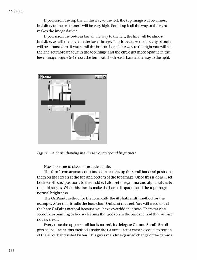
If you scroll the top bar all the way to the left, the top image will be almost invisible, as the brightness will be very high. Scrolling it all the way to the right makes the image darker.
If you scroll the bottom bar all the way to the left, the line will be almost invisible, as will the circle in the lower image. This is because the opacity of both will be almost zero. If you scroll the bottom bar all the way to the right you will see the line get more opaque in the top image and the circle get more opaque in the lower image. Figure 5-4 shows the form with both scroll bars all the way to the right.
Figure 5-4. Form showing maximum opacity and brightness
Now it is time to dissect the code a little.The form’s constructor contains code that sets up the scroll bars and positions
them on the screen at the top and bottom of the top image. Once this is done, I set both scroll bars’ positions to the middle. I also set the gamma and alpha values to the mid ranges. What this does is make the bar half opaque and the top image normal brightness.
The OnPaint method for the form calls the AlphaBlend() method for the example. After this, it calls the base class’ OnPaint method. You will need to call the base OnPaint method because you have overridden it here. There may be some extra painting or housecleaning that goes on in the base method that you are not aware of.
Every time the upper scroll bar is moved, its delegate GammaScroll_Scroll gets called. Inside this method I make the GammaFactor variable equal to potion of the scroll bar divided by ten. This gives me a fine-grained change of the gamma
035c05.fm Page 186 Sunday, May 19, 2002 4:54 PM

Advanced Graphics
187187
factor. Once this is done, I call the form’s OnPaint method. Doing this, of course, calls the overridden OnPaint method, at which point I repaint the screen with objects based on the new values.
The lower scroll bar is essentially the same as the upper one except that it changes the alpha blend factor for both the line and the circle. When the OnPaint method is called, the CompositingMode is set to SourceOver, which blends the image being drawn with the background of the space it is drawn on. If I had set the CompositingMode to SorceCopy, the image of the circle would have completely overlaid the background image of the color bars. Try it if you don’t believe me!
The last thing I do in this example is run code in the form’s Dispose method that calls the Dispose methods of the class-local Image and ImageAttributes objects. I suppose it is not strictly necessary in this example, as the memory will get reclaimed as soon as the program ends, but I feel it is always wise to clean up after yourself.1
You will notice that in both the C# and VB code examples I used a Try-Finally block to contain the drawing code. The Finally block has code that tests the objects
to see if they are real, and then calls the Dispose method on each. This is the way your code should look at all times. As I mentioned in a previous chapter, C# has a Using statement that can take the place of the Finally block of code. I chose not to do this here so you could compare the C# code to the VB code.
My Friend Flicker
I think it is a good time to go over another aspect of painting shapes on forms. I am talking about speed. As you no doubt noticed, there was a problem in viewing the last example. As you moved the pointer on the scroll bar, you saw a lot of flicker on the screen. This is not pretty.
Up to this point you have seen only the simplest way to force the form to repaint. This is accomplished calling the Refresh method of the form. Most other controls also have a Refresh method. All you VB programmers know that this method very well. It is a part of most of the constituent VB 6.0 controls.
It is not uncommon in VB 6.0 to call a control’s Refresh method to force some-thing to appear on the screen. As you have seen, I have also been calling the Refresh method for the form every time I need to show something on the screen. There is a problem, however, with calling the form’s Refresh method.
Calling a form’s Refresh method forces a repaint of everything on that form. If you have a complex form with quite a few painted shapes, calling the Refresh method on the whole form when only one area needs repainting is a waste of time
1. I keep hearing my mother say this: “Clean up after yourself!”
035c05.fm Page 187 Sunday, May 19, 2002 4:54 PM
Chapter 5
188
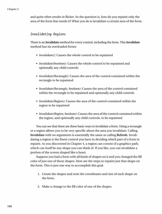
and quite often results in flicker. So the question is, how do you repaint only the area of the form that needs it? What you do is invalidate a certain area of the form.
Invalidating Regions
There is an Invalidate method for every control, including the form. This Invalidate method has six overloaded forms:
• Invalidate(): Causes the whole control to be repainted
• Invalidate(boolean): Causes the whole control to be repainted and optionally any child controls
• Invalidate(Rectangle): Causes the area of the control contained within the rectangle to be repainted
• Invalidate(Rectangle, boolean): Causes the area of the control contained within the rectangle to be repainted and optionally any child controls
• Invalidate(Region): Causes the area of the control contained within the region to be repainted
• Invalidate(Region, boolean): Causes the area of the control contained within the region, and optionally any child controls, to be repainted
You can see that there are three basic ways to invalidate a form. Using a rectangle or a region allows you to be very specific about the area you invalidate. Calling Invalidate with no arguments is essentially the same as calling Refresh. Invali-dating a region is the finest control you have in deciding which part of a form to repaint. As you discovered in Chapter 4, a region can consist of a graphics path, which can itself be any shape you can think of. If you like, you can invalidate a portion of the screen shaped like a heart.
Suppose you had a form with all kinds of shapes on it and you changed the fill color of just one of those shapes. Here are the steps to repaint just that shape on the form. This is just one way to accomplish this goal.
1. Create the shapes and note the coordinates and size of each shape on the form.
2. Make a change to the fill color of one of the shapes.
035c05.fm Page 188 Sunday, May 19, 2002 4:54 PM

Advanced Graphics
189189
3. Make a rectangle with the noted coordinates and size.
4. Call the form’s Invalidate method and pass in the rectangle.
These steps will result in the single shape (and anything else inside the bounding rectangle) being redrawn while the rest of the form is left alone. Consider the following snippet of code:
VB
Me.Invalidate(New Rectangle(New Point(10, 10), _
New Size(50, 50)))
Invalidate(New Rectangle(10, 10, 50, 50))
Me.Invalidate(New Region(New Rectangle(10, 10, 50, 50)))
C#
this.Invalidate( new Rectangle( new Point(10, 10),
new Size(50, 50)));
Invalidate( new Rectangle( 10, 10, 50, 50 ));
this.Invalidate( new Region( new Rectangle(10, 10, 50, 50)));
Each of these calls to the Invalidate event does the same thing: It invalidates a rectangle that starts at 10, 10 and whose width and height are 50 pixels. You can also see from this code that you do not need to qualify the Invalidate event with the form’s identity. Calling Invalidate is the same as calling Me.Invalidate for VB or this.Invalidate for C#.
So is this it? Will this eliminate flicker? Like most things, the answer is maybe. If you have a small enough invalid region and what you are doing is not complex, then this may eliminate flicker. However, while this method goes a long way to solving the problem, there is more that you can do to smooth out the drawing process.
Using Control Styles to Reduce Flicker
The ControlStyles enumeration is a set of bit fields whose bitwise combination defines how the screen is painted. Table 5-2 shows the bit fields and their meanings. There are quite a few members of this enumeration, and only those that have to do with painting are shown in Table 5-2.
035c05.fm Page 189 Sunday, May 19, 2002 4:54 PM

Chapter 5
190
If the AllPaintingInWmPaint bit is set, the control’s OnPaint and OnPaintBackground methods are called directly from the WM_PAINT message. This can greatly reduce flicker.
Double buffering is probably the best way to reduce flicker. All painting is done in a background buffer that mimics the screen’s buffer. After the painting is done in the background, the information is blasted to the foreground.2 To fully enable double buffering, you must set the AllPaintingInWmPaint, DoubleBuffer, and UserPaint control bits.
The method for setting these bits is through the SetStyle and GetStyle members of a control class. The following piece of code shows how this is done:
VB
Dim a As Boolean = Me.GetStyle(ControlStyles.AllPaintingInWmPaint)
Dim b As Boolean = Me.GetStyle(ControlStyles.DoubleBuffer)
Me.SetStyle(ControlStyles.AllPaintingInWmPaint, True)
Me.SetStyle(ControlStyles.DoubleBuffer, True)
Table 5-2. ControlStyles Enumeration Members
Name Description
AllPaintingInWmPaint WM_ERASEBKGND message is ignored to reduce
flicker.
CacheText Control keeps a copy of text instead of getting it
from the text handle.
DoubleBuffer Drawing is done in the background buffer and
then sent to the screen.
Opaque Control is drawn opaque. Background is not
redrawn.
ResizeRedraw Control is redrawn when it is resized.
SupportsTransparentBackColor Control accepts a BackColor whose alpha is less
than 255.
UserPaint Control paints itself rather than the operating
system.
2. Usually during the vertical blanking interrupt.
035c05.fm Page 190 Sunday, May 19, 2002 4:54 PM

Advanced Graphics
191191
C#
bool a = this.GetStyle(ControlStyles.AllPaintingInWmPaint);
bool b = this.GetStyle(ControlStyles.DoubleBuffer);
this.SetStyle ( ControlStyles.AllPaintingInWmPaint, true);
this.SetStyle ( ControlStyles.DoubleBuffer, true);
The next example shows control styles in action.
Painting the Background
There is one last thing you can do to help eliminate flicker. It is possible to paint just the background of a form without touching the foreground images. Why do this? Suppose you needed to change the color of the background based on a user preference. You can do this using the OnPaintBackground method.
This method can be overridden like the OnPaint delegate, and it also takes the same PaintEventArgs argument. This method is not, however, a real event. There is no PaintBackgound event, and a derived class is not required to call the base class’ OnPaintBackground method.
So how do you invoke this method? You need to call the control’s InvokePaintBackgound method:
this.InvokePaintBackground(this, e );
So this is it for speeding up your painting process. In Chapter 6 I show another process for speeding up drawing: bit block transfer.
Blending
You probably think of color blending as adding blue to yellow and coming up with green. While you can do that in .NET (as you shall soon see), the true power of blending is where you start out filling a shape with a particular color and ending the fill with another color. The entire fill in between the start and end colors are
NOTE This ControlStyles enumeration is valid only for those objects that derive from the System.Windows.Forms.Control class. Yes, Windows Forms do derive from this class and therefore have the SetStyle and GetStyle members available.
035c05.fm Page 191 Sunday, May 19, 2002 4:54 PM

Chapter 5
192
even steps of color. For instance, a light blue to red fill would go through all the shades of blue, through purple, and all the way to red.
The two classes that deal with setting up color blends are as follows:
• Blend
• ColorBlend
The two classes that use the blend objects are as follows:
• LinearGradientBrush
• PathGradientBrush
Using these four classes, you can create some truly impressive drawings.
New Blends
The LinearGradientBrush is a brush that has a start color and an end color. It also has a repeat pattern defined by a start point and an end point on the screen. The LinearGradientBrush has eight overloaded constructors that allow you to specify the start and end points as either a rectangle or Point structures. Each of these con-structors also allows you to specify the start and end colors.
The linear gradient part of the brush means that the color is interpolated linearly between the start color and the end color along the length of the repeat pattern. The repeat pattern is defined for the whole graphics container. What this means is that a shape drawn with a LinearGradientBrush will have its start color be the same as the color of the brush’s color at that point in the repeat pattern. Are you confused yet?
In other words, suppose you made a brush that started out blue at point 0, 0 and ended up red at point 100, 100. Now say you drew a rectangle using that brush that started at 50, 50. The first color of your rectangle would be some shade of purple. This is because you started the rectangle at the point where the brush was changing from blue to red.
Well, this is kind of neat, but suppose you wanted to use three or more colors before the pattern repeated? Suppose you wanted to determine where along the pattern the brushes changed colors? A couple of methods in the LinearGradientBrush class allow you to do just that:
• Blend
• InterpolationColors
035c05.fm Page 192 Sunday, May 19, 2002 4:54 PM
Advanced Graphics
193193
The Blend method takes as an argument a Blend object. This object is made up of a set of blending factors and blending positions.
A blending factor is the percentage of the starting and ending colors that are used at the corresponding blending positions.
Blending positions are floating-point values that relate to a percentage of distance along the gradient line. The combination of blending factors and blending positions allows you to create a staircase gradient that goes from a start color to an end color in discrete steps.
InterpolationColors is a method that gets or sets a ColorBlend object that defines how the gradient is formed. The ColorBlend object includes a set of colors and positions. The ColorBlend object is similar to the Blend object, except that instead of defining color factors it defines actual colors to be used at the positions provided. Using InterpolationColors nullifies any colors and positions previously defined for the brush.
The following example is fairly complicated and demonstrates how do to several things, such as
• Use a LinearGradientBrush with default values
• Skew a linear gradient brush
• Draw several shapes along the gradient path
• Shows the complete gradient path
• Change a two-color gradient path
• Change alpha values for a LinearGradientBrush
• Use the Invalidate method to speed up redraw
• Use ControlStyles to speed up redraw
• Use a ColorBlend object to define a set of gradient colors and positions
• Change the gradient using the InterpolationColors method
• Use event handling for scroll bars
035c05.fm Page 193 Sunday, May 19, 2002 4:54 PM

Chapter 5
194
Okay, now start a new VB or C# Windows project. Mine is called GradientBlend. Perform the following steps:
1. Size the form to be 400×400.
2. Set the form’s start-up position to be center screen.
3. Add a horizontal scroll bar. Name it BlendWidth. Placement is not critical.
4. Add a horizontal scroll bar. Name it Skew. Placement is not critical.
5. Add a button. Name it cmdDoubleBuffer. Placement is not critical.
The controls will be moved via code, so it does not matter where you put them on the form.
Next, double-click the controls to get the wizard-generated scroll and button click event handlers. For my C# code, I changed the handler for the Skew control to SkewColor. The handler for the BlendWidth control is called BlendChange. I accepted the default handlers for the VB code. Now go into the code pane and enter the code shown in Listing 5-5. The code shown here is for the whole program except for the form’s InitializeComponent method. This is generated by the wizard and was not touched.
Listing 5-5a. LinearGradientBrush Example in VB
Option Strict On
Imports System
Imports System.Drawing
Imports System.Drawing.Imaging
Imports System.Drawing.Drawing2D
Public Class Form1
Inherits System.Windows.Forms.Form
Private BlWidth As Int32
Private SkewVal As Int32
Private EL1Rect As Rectangle
Private EL2Rect As Rectangle
Private EL1Region As Region
Private EL2Region As Region
Private EL3Region As Region
035c05.fm Page 194 Sunday, May 19, 2002 4:54 PM

Advanced Graphics
195195
#Region " Windows Form Designer generated code "
Public Sub New()
MyBase.New()
'This call is required by the Windows Form Designer.
InitializeComponent()
'Set up rectangles to draw ellipses in
EL1Rect = New Rectangle(10, 10, 150, 50)
EL2Rect = EL1Rect
'I could make a new rectangle but I can offset without knowing
'anything about the previous rectangle.
EL2Rect.Offset(200, 0)
'Set up Regions for invalidation
EL1Region = New Region(EL1Rect)
EL2Region = New Region(EL2Rect)
EL3Region = New Region(New Rectangle(New Point(0, 65), _
New Size(Me.Width, 50)))
'Set up the blend scroll bar
BlendWidth.Top = 120
BlendWidth.Left = CType(Me.Width / 3, Int32)
BlendWidth.Width = CType(Me.Width / 3, Int32)
BlendWidth.Minimum = 10
BlendWidth.Maximum = 200
BlendWidth.SmallChange = 1
BlendWidth.LargeChange = 10
BlendWidth.Value = BlendWidth.Minimum
'Set up the Skew Scroll Bar
Skew.Top = 145
Skew.Left = CType(Me.Width / 3, Int32)
Skew.Width = CType(Me.Width / 3, Int32)
Skew.Minimum = 10
Skew.Maximum = 40
Skew.SmallChange = 1
Skew.LargeChange = 10
Skew.Value = Skew.Minimum
035c05.fm Page 195 Sunday, May 19, 2002 4:54 PM
Chapter 5
196
'Set up the double buffer button
cmdDoubleBuffer.Top = Skew.Top + Skew.Height + 5
cmdDoubleBuffer.Width = Skew.Width
cmdDoubleBuffer.Left = Skew.Left
cmdDoubleBuffer.Text = "Allow Flicker"
BlWidth = BlendWidth.Value
SkewVal = Skew.Value
' Set up for double buffering.
'This, along with invalidating only those areas that need it, TOTALLY
'eliminates flicker in this program
Me.SetStyle(ControlStyles.AllPaintingInWmPaint, True)
Me.SetStyle(ControlStyles.DoubleBuffer, True)
Me.SetStyle(ControlStyles.UserPaint, True)
End Sub
'Form overrides dispose to clean up the component list.
Protected Overloads Overrides Sub Dispose(ByVal disposing As Boolean)
If disposing Then
If Not (components Is Nothing) Then
components.Dispose()
End If
'Dispose of our own objects
EL1Region.Dispose()
EL2Region.Dispose()
EL3Region.Dispose()
End If
MyBase.Dispose(disposing)
End Sub
'Required by the Windows Form Designer
Private components As System.ComponentModel.IContainer
'NOTE: The following procedure is required by the Windows Form Designer
'It can be modified using the Windows Form Designer.
'Do not modify it using the code editor.
Friend WithEvents cmdDoubleBuffer As System.Windows.Forms.Button
Friend WithEvents Skew As System.Windows.Forms.HScrollBar
Friend WithEvents BlendWidth As System.Windows.Forms.HScrollBar
<System.Diagnostics.DebuggerStepThrough()> Private Sub InitializeComponent()
…
…
End Sub
035c05.fm Page 196 Sunday, May 19, 2002 4:54 PM
Advanced Graphics
197197
#End Region
Private Sub Form1_Load(ByVal sender As System.Object, _
ByVal e As System.EventArgs) _
Handles MyBase.Load
End Sub
Protected Overrides Sub OnPaint(ByVal e As PaintEventArgs)
e.Graphics.SmoothingMode = SmoothingMode.AntiAlias
StandardGradient(e.Graphics)
e.Graphics.DrawLine(Pens.Black, 0, cmdDoubleBuffer.Bottom + 10, Me.Width, _
cmdDoubleBuffer.Bottom + 10)
InterpolateGradient(e.Graphics)
MyBase.OnPaint(e)
End Sub
Private Sub StandardGradient(ByVal G As Graphics)
'This brush defines how the color is distributed across the whole
'graphics container. Any filled object that gets drawn in the container
'will pick up the color starting with the color gradient at that
'particular point on the screen.
Dim B As LinearGradientBrush = New LinearGradientBrush(New PointF(0, 20), _
New PointF(BlWidth, SkewVal), _
Color.Blue, _
Color.Red)
'Draw an image inside the second rectangle
G.DrawImage(Image.FromFile("D:\\Colorbars.jpg"), EL2Rect)
'Draw a line across the screen with the brush
'to show the repeating pattern
Dim P As Pen = New Pen(B, 15)
G.DrawLine(P, 0, 75, Me.Width, 75)
'Draw a filled ellipse to show how the colors are used
G.FillEllipse(B, EL1Rect)
035c05.fm Page 197 Sunday, May 19, 2002 4:54 PM

Chapter 5
198
'Change the starting and ending colors
'Set the alpha so the image below shows through
Dim c() As Color = {Color.FromArgb(100, Color.LightBlue), _
Color.FromArgb(100, Color.DarkBlue)}
B.LinearColors = c
P.Brush = B
G.DrawLine(P, 0, 100, Me.Width, 100)
G.FillEllipse(B, EL2Rect)
'Reclaim some memory
c = Nothing
If Not P Is Nothing Then
P.Dispose()
End If
If Not B Is Nothing Then
B.Dispose()
End If
End Sub
Private Sub InterpolateGradient(ByVal G As Graphics)
'Make a set of colors to use in the blend
Dim EndColors() As Color = {Color.Green, _
Color.Yellow, _
Color.Yellow, _
Color.Blue, _
Color.Red, _
Color.Red}
'These are the positions of the colors along the Gradient line
Dim ColorPositions() As Single = {0.0F, 0.2F, 0.4F, 0.6F, 0.8F, 1.0F}
'Fill the blend object with the colors and their positions
Dim C_Blend As ColorBlend = New ColorBlend()
C_Blend.Colors = EndColors
C_Blend.Positions = ColorPositions
'Make the linear brush and assign the custom blend to it
Dim B As LinearGradientBrush = New LinearGradientBrush(New Point(10, 110), _
New Point(140, 110), _
Color.White, _
Color.Black)
B.InterpolationColors = C_Blend
035c05.fm Page 198 Sunday, May 19, 2002 4:54 PM

Advanced Graphics
199199
'Make a graphics path that we can fill and show custom blended fill
Dim Pth As GraphicsPath = New GraphicsPath()
Pth.AddEllipse(20, 210, 120, 50)
Pth.AddString("Filled String", New FontFamily("Impact"), _
CType(FontStyle.Italic, Int32), 30, New Point(200, 220), _
StringFormat.GenericDefault)
G.FillPath(B, Pth)
Dim P As Pen = New Pen(B, 20)
G.DrawLine(P, 0, 300, Me.Width, 300)
If Not P Is Nothing Then
P.Dispose()
End If
If Not B Is Nothing Then
B.Dispose()
End If
If Not Pth Is Nothing Then
Pth.Dispose()
End If
End Sub
Private Sub BlendWidth_Scroll(ByVal sender As System.Object, ByVal e As
System.Windows.Forms.ScrollEventArgs) Handles BlendWidth.Scroll
BlWidth = BlendWidth.Value
'Redraw the first ellipse
Me.Invalidate(EL1Region)
'Redraw the second ellipse
Me.Invalidate(EL2Region)
'Redraw the lines
Me.Invalidate(EL3Region)
End Sub
Private Sub Skew_Scroll(ByVal sender As System.Object, _
ByVal e As _
System.Windows.Forms.ScrollEventArgs) _
Handles Skew.Scroll
035c05.fm Page 199 Sunday, May 19, 2002 4:54 PM
Chapter 5
200
SkewVal = Skew.Value
'Redraw the first ellipse
Me.Invalidate(EL1Region)
'Redraw the second ellipse
Me.Invalidate(EL2Region)
'Redraw the lines
Invalidate(EL3Region)
End Sub
Private Sub cmdDoubleBuffer_Click(ByVal sender As System.Object, _
ByVal e As System.EventArgs) Handles cmdDoubleBuffer.Click
If Me.GetStyle(ControlStyles.AllPaintingInWmPaint) And _
Me.GetStyle(ControlStyles.DoubleBuffer) And _
Me.GetStyle(ControlStyles.UserPaint) Then
cmdDoubleBuffer.Text = "Eliminate Flicker"
Me.SetStyle(ControlStyles.AllPaintingInWmPaint, False)
Me.SetStyle(ControlStyles.DoubleBuffer, False)
Else
cmdDoubleBuffer.Text = "Allow Flicker"
Me.SetStyle(ControlStyles.AllPaintingInWmPaint, True)
Me.SetStyle(ControlStyles.DoubleBuffer, True)
End If
End Sub
End Class
Listing 5-5b. LinearGradientBrush Example in C#
using System;
using System.Drawing;
using System.Drawing.Imaging;
using System.Drawing.Drawing2D;
using System.Collections;
using System.ComponentModel;
using System.Windows.Forms;
using System.Data;
035c05.fm Page 200 Sunday, May 19, 2002 4:54 PM
Advanced Graphics
201201
namespace GradientBlend_c
{
/// <summary>
/// Summary description for Form1.
/// </summary>
public class Form1 : System.Windows.Forms.Form
{
private System.Windows.Forms.HScrollBar BlendWidth;
private System.ComponentModel.Container components = null;
private System.Windows.Forms.HScrollBar Skew;
private System.Windows.Forms.Button cmdDoubleBuffer;
private int BlWidth;
private int SkewVal;
private Rectangle EL1Rect;
private Rectangle EL2Rect;
private Region EL1Region;
private Region EL2Region;
private Region EL3Region;
public Form1()
{
//
// Required for Windows Form Designer support
//
InitializeComponent();
//Set up rectangles to draw ellipses in
EL1Rect = new Rectangle(10, 10, 150, 50);
EL2Rect = EL1Rect;
//I could make a new rectangle but I can offset without knowing
//anything about the previous rectangle.
EL2Rect.Offset(200, 0);
//Set up Regions for invalidation
EL1Region = new Region(EL1Rect);
EL2Region = new Region(EL2Rect);
EL3Region = new Region( new Rectangle(new Point(0, 65),
new Size(this.Width, 50)));
035c05.fm Page 201 Sunday, May 19, 2002 4:54 PM

Chapter 5
202
//Set up the blend scroll bar
BlendWidth.Top = 120;
BlendWidth.Left = this.Width/3;
BlendWidth.Width = this.Width/3;
BlendWidth.Minimum = 10;
BlendWidth.Maximum = 200;
BlendWidth.SmallChange = 1;
BlendWidth.LargeChange = 10;
BlendWidth.Value = BlendWidth.Minimum;
//Set up the Skew Scroll Bar
Skew.Top = 145;
Skew.Left = this.Width/3;
Skew.Width = this.Width/3;
Skew.Minimum = 10;
Skew.Maximum = 40;
Skew.SmallChange = 1;
Skew.LargeChange = 10;
Skew.Value = Skew.Minimum;
//Set up the double buffer button
cmdDoubleBuffer.Top = Skew.Top + Skew.Height + 5;
cmdDoubleBuffer.Width = Skew.Width;
cmdDoubleBuffer.Left = Skew.Left;
cmdDoubleBuffer.Text = "Allow Flicker";
BlWidth = BlendWidth.Value;
SkewVal = Skew.Value;
// Set up for double buffering.
//This, along with invalidating only those areas that need it, TOTALLY
//eliminates flicker in this program
this.SetStyle ( ControlStyles.AllPaintingInWmPaint, true);
this.SetStyle ( ControlStyles.DoubleBuffer, true);
this.SetStyle ( ControlStyles.UserPaint, true);
}
035c05.fm Page 202 Sunday, May 19, 2002 4:54 PM
Advanced Graphics
203203
/// <summary>
/// Clean up any resources being used.
/// </summary>
protected override void Dispose( bool disposing )
{
if( disposing )
{
if (components != null)
{
components.Dispose();
}
//Dispose of our own objects
EL1Region.Dispose();
EL2Region.Dispose();
EL3Region.Dispose();
}
base.Dispose( disposing );
}
#region Windows Form Designer generated code
/// <summary>
/// Required method for Designer support - do not modify
/// the contents of this method with the code editor.
/// </summary>
private void InitializeComponent()
{
this.BlendWidth = new System.Windows.Forms.HScrollBar();
this.Skew = new System.Windows.Forms.HScrollBar();
this.cmdDoubleBuffer = new System.Windows.Forms.Button();
this.SuspendLayout();
//
// BlendWidth
//
this.BlendWidth.Location = new System.Drawing.Point(32, 224);
this.BlendWidth.Name = "BlendWidth";
this.BlendWidth.Size = new System.Drawing.Size(192, 16);
this.BlendWidth.TabIndex = 0;
this.BlendWidth.Scroll += new
System.Windows.Forms.ScrollEventHandler
(this.BlendChange);
035c05.fm Page 203 Sunday, May 19, 2002 4:54 PM

Chapter 5
204
//
// Skew
//
this.Skew.Location = new System.Drawing.Point(192, 272);
this.Skew.Name = "Skew";
this.Skew.Size = new System.Drawing.Size(104, 16);
this.Skew.TabIndex = 1;
this.Skew.Scroll += new
System.Windows.Forms.ScrollEventHandler
(this.SkewColor);
//
// cmdDoubleBuffer
//
this.cmdDoubleBuffer.Location = new System.Drawing.Point(40, 304);
this.cmdDoubleBuffer.Name = "cmdDoubleBuffer";
this.cmdDoubleBuffer.Size = new System.Drawing.Size(248, 24);
this.cmdDoubleBuffer.TabIndex = 2;
this.cmdDoubleBuffer.Text = "button1";
this.cmdDoubleBuffer.Click += new
System.EventHandler
(this.cmdDoubleBuffer_Click);
//
// Form1
//
this.AutoScaleBaseSize = new System.Drawing.Size(5, 13);
this.ClientSize = new System.Drawing.Size(392, 373);
this.Controls.AddRange(new System.Windows.Forms.Control[]
{this.cmdDoubleBuffer, this.Skew,
this.BlendWidth});
this.Name = "Form1";
this.StartPosition = System.Windows.Forms.FormStartPosition.CenterScreen;
this.Text = "Form1";
this.Load += new System.EventHandler(this.Form1_Load);
this.ResumeLayout(false);
}
#endregion
035c05.fm Page 204 Sunday, May 19, 2002 4:54 PM
Advanced Graphics
205205
/// <summary>
/// The main entry point for the application.
/// </summary>
[STAThread]
static void Main()
{
Application.Run(new Form1());
}
private void Form1_Load(object sender, System.EventArgs e)
{
}
protected override void OnPaint ( PaintEventArgs e )
{
e.Graphics.SmoothingMode=SmoothingMode.AntiAlias;
StandardGradient( e.Graphics );
e.Graphics.DrawLine(Pens.Black, 0, cmdDoubleBuffer.Bottom+10, this.Width,
cmdDoubleBuffer.Bottom+10);
InterpolateGradient( e.Graphics );
base.OnPaint(e);
}
private void StandardGradient( Graphics G )
{
//This brush defines how the color is distributed across the whole
//graphics container. Any filled object that gets drawn in the container
//will pick up the color starting with the color gradient at that
//particular point on the screen.
LinearGradientBrush B = new LinearGradientBrush(new PointF(0, 20),
new PointF(BlWidth, SkewVal),
Color.Blue,
Color.Red);
//Draw an image inside the second rectangle
G.DrawImage(Image.FromFile("D:\\Colorbars.jpg"), EL2Rect);
//Draw a line across the screen with the brush
//to show the repeating pattern
Pen P = new Pen(B, 15);
G.DrawLine ( P, 0, 75, this.Width, 75 );
//Draw a filled ellipse to show how the colors are used
G.FillEllipse(B, EL1Rect);
035c05.fm Page 205 Sunday, May 19, 2002 4:54 PM

Chapter 5
206
//Change the starting and ending colors
//Set the alpha so the image below shows through
Color[] c = {Color.FromArgb(100, Color.LightBlue),
Color.FromArgb(100, Color.DarkBlue)};
B.LinearColors = c;
P.Brush = B;
G.DrawLine ( P, 0, 100, this.Width, 100 );
G.FillEllipse(B, EL2Rect );
//Reclaim some memory
c = null;
P.Dispose();
B.Dispose();
}
private void InterpolateGradient ( Graphics G )
{
//Make a set of colors to use in the blend
Color[] EndColors = {Color.Green,
Color.Yellow,
Color.Yellow,
Color.Blue,
Color.Red,
Color.Red};
//These are the positions of the colors along the Gradient line
float[] ColorPositions = {0.0f, .20f, .40f, .60f, .80f, 1.0f};
//Fill the blend object with the colors and their positions
ColorBlend C_Blend = new ColorBlend();
C_Blend.Colors = EndColors;
C_Blend.Positions = ColorPositions;
//Make the linear brush and assign the custom blend to it
LinearGradientBrush B = new LinearGradientBrush ( new Point(10, 110),
new Point(140, 110),
Color.White,
Color.Black );
B.InterpolationColors = C_Blend;
035c05.fm Page 206 Sunday, May 19, 2002 4:54 PM

Advanced Graphics
207207
//Make a graphics path that we can fill and show custom blended fill
GraphicsPath Pth = new GraphicsPath();
Pth.AddEllipse(20, 210, 120, 50);
Pth.AddString("Filled String", new FontFamily("Impact"),
(int)FontStyle.Italic, 30, new Point(200, 220),
StringFormat.GenericDefault );
G.FillPath(B, Pth);
Pen P = new Pen(B, 20);
G.DrawLine ( P, 0, 300, this.Width, 300 );
if (P != null)
P.Dispose();
if (B != null)
B.Dispose();
if (Pth != null)
Pth.Dispose();
}
private void BlendChange(object sender,
System.Windows.Forms.ScrollEventArgs e)
{
BlWidth = BlendWidth.Value;
//Redraw the first ellipse
this.Invalidate(EL1Region);
//Redraw the second ellipse
this.Invalidate(EL2Region);
//Redraw the lines
this.Invalidate(EL3Region);
}
private void SkewColor(object sender,
System.Windows.Forms.ScrollEventArgs e)
{
SkewVal = Skew.Value;
//Redraw the first ellipse
this.Invalidate(EL1Region);
//Redraw the second ellipse
this.Invalidate(EL2Region);
//Redraw the lines
Invalidate(EL3Region);
}
035c05.fm Page 207 Sunday, May 19, 2002 4:54 PM

Chapter 5
208
private void cmdDoubleBuffer_Click(object sender, System.EventArgs e)
{
if ( this.GetStyle( ControlStyles.AllPaintingInWmPaint ) &&
this.GetStyle( ControlStyles.DoubleBuffer ) &&
this.GetStyle( ControlStyles.UserPaint ) )
{
cmdDoubleBuffer.Text = "Eliminate Flicker";
this.SetStyle ( ControlStyles.AllPaintingInWmPaint, false);
this.SetStyle ( ControlStyles.DoubleBuffer, false);
}
else
{
cmdDoubleBuffer.Text = "Allow Flicker";
this.SetStyle ( ControlStyles.AllPaintingInWmPaint, true);
this.SetStyle ( ControlStyles.DoubleBuffer, true);
}
}
}
}
This seems like a big program for such a limited example. Or is it? I could have written the standard “draw a simple static shape using defaults” example. I believe, however, you will learn a lot more than just some GDI programming from this example. It also teaches you how to weave quite a few concepts together. This is just as important, I think, as the concepts themselves.
By the way, if you want, you can download the code from Downloads section of the Apress Web site (http://www.apress.com) if you do not want to enter it manually.3
So what does this example look like when it runs? Figure 5-5 shows the screen as it starts up.
As you can see, there are quite a few things on the screen. The screen is also divided into two sections. First of all, look at the top part of the screen. The upper scroll bar changes the repeat distance of the color pattern. The lower scroll bar changes the skew of the pattern. The pattern is skewed to the left. The button below the scroll bars changes some of the painting parameters to prevent flicker.
Try running the program and playing with the scroll bars and antiflicker button. Pretty cool stuff. You will see that the top right-hand ellipse has an alpha component to it and is drawn as a transparent image on top of the color bars’ picture. Figure 5-6 shows this screen with the blend scroll bar to the right and the skew as vertical. The blend repeat pattern is much longer.
3. I encourage you to enter as much as you can. You will learn so much more from making mistakes than not trying.
035c05.fm Page 208 Sunday, May 19, 2002 4:54 PM

Advanced Graphics
209209
Figure 5-5. Starting screen of the LinearGradientBrush example
Figure 5-6. Longer blend repeat pattern and no skew
035c05.fm Page 209 Sunday, May 19, 2002 4:54 PM

Chapter 5
210
Turn off the antiflicker and you will see the top half of the screen flicker as you move the scroll bars. You will also notice that the bottom images do not flicker. This is because you are invalidating only those portions of the screen that are affected by the scroll bars. Turn on the antiflicker and the painting will be very smooth. No tearing or flicker.
The bottom half of the screen is painted only once. It is a LinearGradientBrush that has four colors for its pattern. Also, the pattern repeats at odd intervals to create an interesting gradient. The string and ellipse are part of the same path. When this path is filled, both the ellipse and the string get filled at the same time using just one call.
The antiflicker is accomplished by setting the ControlStyles properties to enable double buffering. As you can see, this is very effective.
Creating a PathGradientBrush
I said I would talk about the last two brushes, and so far I have only mentioned one of them: the LinearGradientBrush. The last one is called the PathGradientBrush.
Where a LinearGradientBrush started out with one color at the start point and ended with another color at the end point, the PathGradientBrush starts with a color at the center of a path and ends with another color at the outer edge of the path.
The classic example is comparing a line that starts out as blue and ends with red to a circle whose center is blue and whose outer edges end with red. Both kinds of brushes can have an unlimited number of colors between the start and end colors and they can place those colors anywhere along the gradient path.
My personal opinion is that the PathGradientBrush is the cooler of the two brushes, and the next two examples will show you just one application of this brush. For now, though, I think it is best to explain the behavior of this brush in detail.
The PathGradientBrush has five overloaded constructors. All the constructors take either a path or an array of points. Since a path can be made up of an array of points, in this case, they are the same. Two of the constructors take an extra argument called a WrapMode.
What is a WrapMode? Basically, it is a way of telling the drawing method how a gradient is to be tiled when the object lies outside the gradient area. As you will see, the gradient path has a size that can be different from the size of the shape you are filling.
035c05.fm Page 210 Sunday, May 19, 2002 4:54 PM
Advanced Graphics
211211
Table 5-3 shows the WrapMode enumeration and describes what each member means.
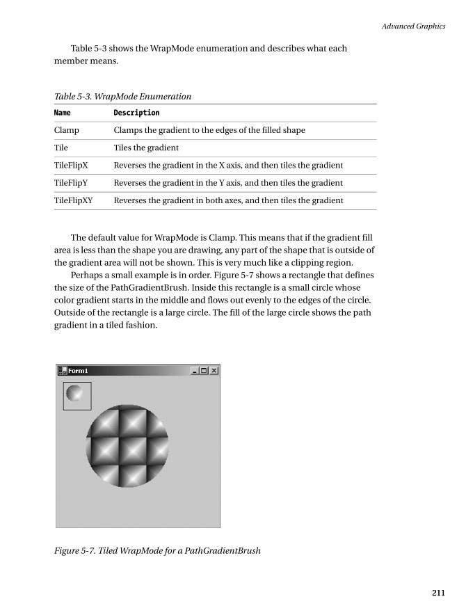
The default value for WrapMode is Clamp. This means that if the gradient fill area is less than the shape you are drawing, any part of the shape that is outside of the gradient area will not be shown. This is very much like a clipping region.
Perhaps a small example is in order. Figure 5-7 shows a rectangle that defines the size of the PathGradientBrush. Inside this rectangle is a small circle whose color gradient starts in the middle and flows out evenly to the edges of the circle. Outside of the rectangle is a large circle. The fill of the large circle shows the path gradient in a tiled fashion.
Figure 5-7. Tiled WrapMode for a PathGradientBrush
Table 5-3. WrapMode Enumeration
Name Description
Clamp Clamps the gradient to the edges of the filled shape
Tile Tiles the gradient
TileFlipX Reverses the gradient in the X axis, and then tiles the gradient
TileFlipY Reverses the gradient in the Y axis, and then tiles the gradient
TileFlipXY Reverses the gradient in both axes, and then tiles the gradient
035c05.fm Page 211 Sunday, May 19, 2002 4:54 PM
Chapter 5
212
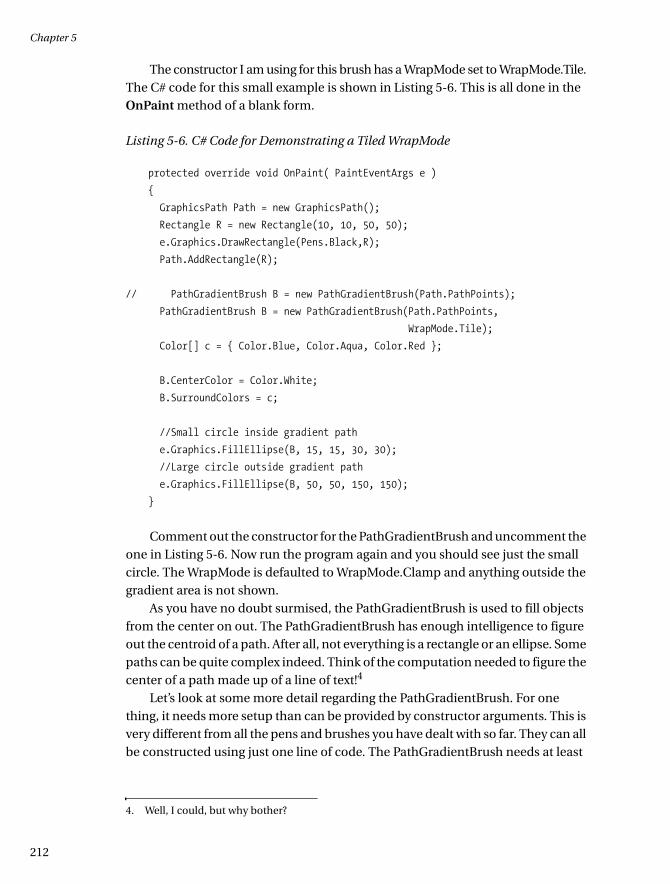
The constructor I am using for this brush has a WrapMode set to WrapMode.Tile. The C# code for this small example is shown in Listing 5-6. This is all done in the OnPaint method of a blank form.
Listing 5-6. C# Code for Demonstrating a Tiled WrapMode
protected override void OnPaint( PaintEventArgs e )
{
GraphicsPath Path = new GraphicsPath();
Rectangle R = new Rectangle(10, 10, 50, 50);
e.Graphics.DrawRectangle(Pens.Black,R);
Path.AddRectangle(R);
// PathGradientBrush B = new PathGradientBrush(Path.PathPoints);
PathGradientBrush B = new PathGradientBrush(Path.PathPoints,
WrapMode.Tile);
Color[] c = { Color.Blue, Color.Aqua, Color.Red };
B.CenterColor = Color.White;
B.SurroundColors = c;
//Small circle inside gradient path
e.Graphics.FillEllipse(B, 15, 15, 30, 30);
//Large circle outside gradient path
e.Graphics.FillEllipse(B, 50, 50, 150, 150);
}
Comment out the constructor for the PathGradientBrush and uncomment the one in Listing 5-6. Now run the program again and you should see just the small circle. The WrapMode is defaulted to WrapMode.Clamp and anything outside the gradient area is not shown.
As you have no doubt surmised, the PathGradientBrush is used to fill objects from the center on out. The PathGradientBrush has enough intelligence to figure out the centroid of a path. After all, not everything is a rectangle or an ellipse. Some paths can be quite complex indeed. Think of the computation needed to figure the center of a path made up of a line of text!4
Let’s look at some more detail regarding the PathGradientBrush. For one thing, it needs more setup than can be provided by constructor arguments. This is very different from all the pens and brushes you have dealt with so far. They can all be constructed using just one line of code. The PathGradientBrush needs at least
4. Well, I could, but why bother?
035c05.fm Page 212 Sunday, May 19, 2002 4:54 PM

Advanced Graphics
213213
two more pieces of information: the center color and the color array that leads to the outer color.
Several properties to this brush can greatly change the way it behaves:
• Blend
• CenterColor
• CenterPoint
• FocusScales
• InterpolationColors
• Rectangle
• SurroundColors
• Transform
• WrapMode
You have already seen WrapMode. You also know about CenterColor from the example in Listing 5-6. Transform is a subject you will deal with a little later in this chapter.
The Blend object and InterpolationColors were explained in the previous section about the LinearGradientBrush.
The Rectangle object defines the rectangle that surrounds the gradient path. Even though the path may be complex and convoluted, this method returns the rectangle structure that surrounds that path. Often this rectangle is called the bounding rectangle.
SurroundColors is an array of colors that corresponds with the array of points that make up the path.
The CenterPoint is calculated by the object itself from the path given at con-struction. This property can be written to as well. You can change the center point to be anywhere in world coordinate space. Yes, this means that the center of the gradient path can be outside of the path itself. You will take advantage of this fact in the next example.
The FocusScales property is interesting indeed. It acts as a lens on the center of the gradient. It creates a scaled path inside the original gradient path whose color is the center color. The FocusScales property is a PointF structure whose first value is the scaling factor in the X direction. The second value is the scaling factor in the Y direction. Both values are normalized and range from 0 to 1.
035c05.fm Page 213 Sunday, May 19, 2002 4:54 PM
Chapter 5
214
Using the FocusScales property, you can create a cat’s eye by defining a hori-zontal ellipse whose FocusScales property is larger in the Y direction than in the X direction. The MSDN help on PathGradients has a good example of using this property.
Now you know all the theory behind a PathGradientBrush. I have given you a small, static example of drawing a shape outside the gradient to see what happens. As you have probably guessed, though, I am not a big fan of static examples. You are not about to go drawing simple pictures your whole career. You also need to know how to use some of what I am talking about in an interactive program. The LinearGradientBrush example was interactive and showed you how you could use OnPaint method effectively in a real situation.
The next example is also interactive. It will, however, be somewhat more dif-ficult. Because of this, it will also be very cool. This example contains two shape objects. One of those objects will be contained in its own class. This is what the C++ guys call a “wrapper.”
Why wrap a shape in a class? One of the points to object-oriented programming is
information hiding. This class will accomplish some complicated things and it will also know how to draw itself on the screen. All this functionality is hidden behind a very simple interface. This shape object will move around the screen and respond to mouse events. The shape that is not wrapped in a class is static. I draw it on the screen in the same place all the time. Only some of the properties change. No need for a class here.
So, let’s begin. Here are some features you will see in this program:
• Your own class
• Overloaded constructors
• Read/Write properties
• ReadOnly properties
• Class methods
• Mouse events
• Mouse tracking
• PathGradientBrush
• AntiFlicker redraw
• Changes in the centroid of a shape object
035c05.fm Page 214 Sunday, May 19, 2002 4:54 PM

Advanced Graphics
215215
Start a new VB or C# project. My examples are called PathBlend-c and PathBlend-vb. There are no controls for this form, so accept the defaults and go straight into the code pane.
The next step is to add a new class. There are several ways to do this—here is one way:
1. Right-click the project name in the Solution Explorer.
2. Choose Add and then choose Add Class.
3. Name the class Centroid.
This procedure is the same for VB and for C#.
Your Solution Explorer should have one form and one class. It should look like Figure 5-8.
Figure 5-8. Solution Explorer for Listing 5-7
The VB classes will have an extension of .vb.Bring up the Centroid class and enter the code shown in Listing 5-7a. This
class is a wrapper for a circle that will act as the centroid for a much larger circle.
NOTE I encourage you to enter the code for both language versions of this example. This example brings out some of the disparate syntax between both languages. It is interesting to see how C# and VB accomplish the same thing.
035c05.fm Page 215 Sunday, May 19, 2002 4:54 PM

Chapter 5
216
Listing 5-7a. Code for the Centroid Wrapper Class
C#
using System;
using System.Drawing;
using System.Drawing.Drawing2D;
namespace PathBlend_c
{
/// <summary>
/// This class acts a centroid for another shape
/// There is no Dispose() method for this class
/// because it consumes
/// no resources
/// </summary>
public class Centroid
{
const int w = 20;
const int h = 20;
private int m_StartX; // Top left X
private int m_StartY; // Top left Y
private Rectangle r; // Rectangle that holds the circle
#region Constructors / Destructors
public Centroid()
{
m_StartX = 10;
m_StartY = 10;
r.X = 10;
r.Y = 10;
r.Width = w;
r.Height = h;
}
public Centroid( int X, int Y )
{
m_StartX = X;
m_StartY = Y;
r.X = X;
r.Y = Y;
r.Width = w;
r.Height = h;
}
035c05.fm Page 216 Sunday, May 19, 2002 4:54 PM

Advanced Graphics
217217
#endregion
#region Properties
public int X
{
get { return m_StartX; }
set
{
m_StartX = value;
r.X = value;
}
}
public int Y
{
get { return m_StartY; }
set
{
m_StartY = value;
r.Y = value;
}
}
public Rectangle Rect
{
get { return r; }
}
public Point Center
{
get { return (new Point((r.Left+r.Width/2), r.Top+r.Height/2)); }
}
#endregion
#region Methods
public void Draw( Graphics G )
{
G.FillEllipse(Brushes.Aqua, r);
}
035c05.fm Page 217 Sunday, May 19, 2002 4:54 PM
Chapter 5
218
public bool Relocate( System.Windows.Forms.MouseEventArgs e )
{
if ( e.Button == System.Windows.Forms.MouseButtons.Left )
{
if ( (e.X > r.Left) && (e.X < r.Right) &&
(e.Y > r.Top) && (e.Y < r.Bottom) )
{
//Must make the center of the rectangle = x,y
//If you don't you will lose track of the ball
r.X = e.X - r.Width/2;
m_StartX = r.X;
r.Y = e.Y - r.Height/2;
m_StartY = r.Y;
return(true);
}
}
return(false);
}
#endregion
}
}
VB
Option Strict On
Imports System
Imports System.Drawing
Imports System.Drawing.Drawing2D
Public Class Centroid
Const w As Int32 = 20
Const h As Int32 = 20
Private m_StartX As Int32 ' Top left X
Private m_StartY As Int32 ' Top left Y
Private r As Rectangle ' Rectangle that holds the circle
035c05.fm Page 218 Sunday, May 19, 2002 4:54 PM
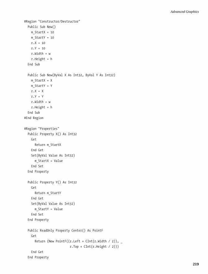
Advanced Graphics
219219
#Region "Constructor/Destructor"
Public Sub New()
m_StartX = 10
m_StartY = 10
r.X = 10
r.Y = 10
r.Width = w
r.Height = h
End Sub
Public Sub New(ByVal X As Int32, ByVal Y As Int32)
m_StartX = X
m_StartY = Y
r.X = X
r.Y = Y
r.Width = w
r.Height = h
End Sub
#End Region
#Region "Properties"
Public Property X() As Int32
Get
Return m_StartX
End Get
Set(ByVal Value As Int32)
m_StartX = Value
End Set
End Property
Public Property Y() As Int32
Get
Return m_StartY
End Get
Set(ByVal Value As Int32)
m_StartY = Value
End Set
End Property
Public ReadOnly Property Center() As PointF
Get
Return (New PointF((r.Left + CInt(r.Width / 2)), _
r.Top + CInt(r.Height / 2)))
End Get
End Property
035c05.fm Page 219 Sunday, May 19, 2002 4:54 PM

Chapter 5
220
Public ReadOnly Property Rect() As Rectangle
Get
Return r
End Get
End Property
#End Region
#Region "Methods"
Public Sub Draw(ByVal G As Graphics)
G.FillEllipse(Brushes.Aqua, r)
End Sub
Public Function Relocate(ByVal e As System.Windows.Forms.MouseEventArgs) _
As Boolean
If e.Button = System.Windows.Forms.MouseButtons.Left Then
If ((e.X > r.Left) And (e.X < r.Right) And _
(e.Y > r.Top) And (e.Y < r.Bottom)) Then
'Must make the center of the rectangle = x,y
'If you don't you will lose track of the ball
r.X = e.X - CInt(r.Width / 2)
m_StartX = r.X
r.Y = e.Y - CInt(r.Height / 2)
m_StartY = r.Y
Return (True)
End If
End If
Return (False)
End Function
#End Region
End Class
This class has two overloaded constructors. The default one makes the centroid at a fixed place on the screen. The second one takes x and y coordinates to make the centroid anywhere on the screen you want.
This class also has several accessor properties and two methods. One of the methods tells the object to relocate itself on the screen according to mouse coor-dinates and the other method tells the object to draw itself.
Once you are able to compile this code, switch back to the form’s code pane. This is where all the action happens. Listing 5-7b shows the code for this form. All the code, including the wizard code, is shown here.
035c05.fm Page 220 Sunday, May 19, 2002 4:54 PM
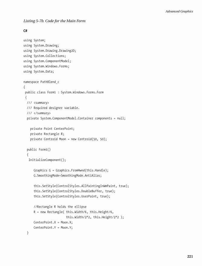
Advanced Graphics
221221
Listing 5-7b. Code for the Main Form
C#
using System;
using System.Drawing;
using System.Drawing.Drawing2D;
using System.Collections;
using System.ComponentModel;
using System.Windows.Forms;
using System.Data;
namespace PathBlend_c
{
public class Form1 : System.Windows.Forms.Form
{
/// <summary>
/// Required designer variable.
/// </summary>
private System.ComponentModel.Container components = null;
private Point CenterPoint;
private Rectangle R;
private Centroid Moon = new Centroid(50, 50);
public Form1()
{
InitializeComponent();
Graphics G = Graphics.FromHwnd(this.Handle);
G.SmoothingMode=SmoothingMode.AntiAlias;
this.SetStyle(ControlStyles.AllPaintingInWmPaint, true);
this.SetStyle(ControlStyles.DoubleBuffer, true);
this.SetStyle(ControlStyles.UserPaint, true);
//Rectangle R holds the ellipse
R = new Rectangle( this.Width/6, this.Height/6,
this.Width/3*2, this.Height/3*2 );
CenterPoint.X = Moon.X;
CenterPoint.Y = Moon.Y;
}
035c05.fm Page 221 Sunday, May 19, 2002 4:54 PM
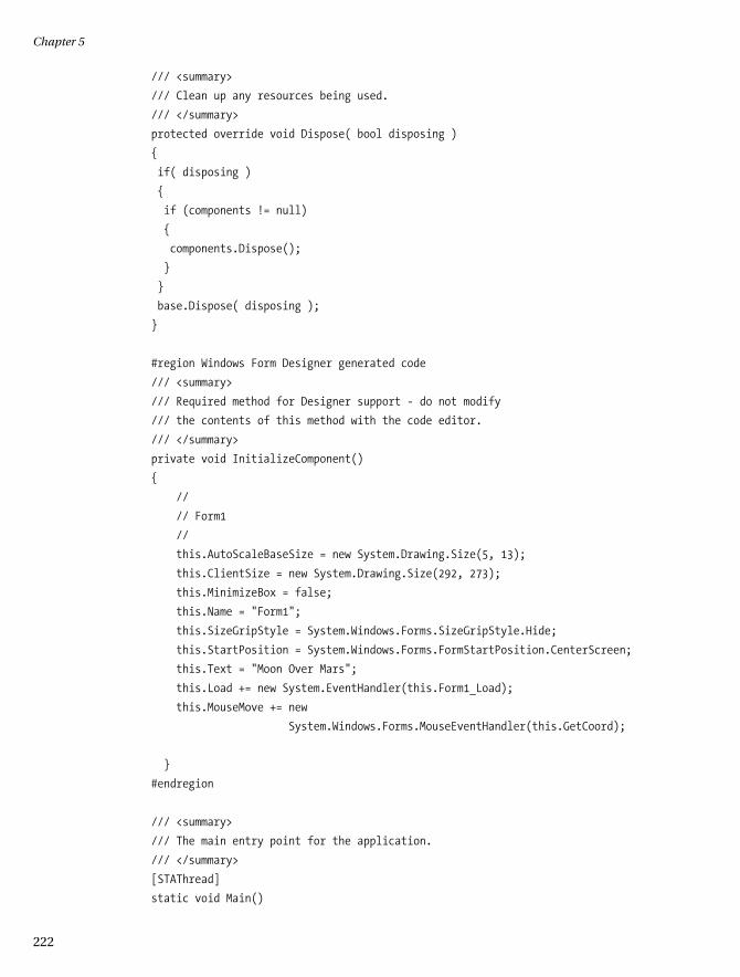
Chapter 5
222
/// <summary>
/// Clean up any resources being used.
/// </summary>
protected override void Dispose( bool disposing )
{
if( disposing )
{
if (components != null)
{
components.Dispose();
}
}
base.Dispose( disposing );
}
#region Windows Form Designer generated code
/// <summary>
/// Required method for Designer support - do not modify
/// the contents of this method with the code editor.
/// </summary>
private void InitializeComponent()
{
//
// Form1
//
this.AutoScaleBaseSize = new System.Drawing.Size(5, 13);
this.ClientSize = new System.Drawing.Size(292, 273);
this.MinimizeBox = false;
this.Name = "Form1";
this.SizeGripStyle = System.Windows.Forms.SizeGripStyle.Hide;
this.StartPosition = System.Windows.Forms.FormStartPosition.CenterScreen;
this.Text = "Moon Over Mars";
this.Load += new System.EventHandler(this.Form1_Load);
this.MouseMove += new
System.Windows.Forms.MouseEventHandler(this.GetCoord);
}
#endregion
/// <summary>
/// The main entry point for the application.
/// </summary>
[STAThread]
static void Main()
035c05.fm Page 222 Sunday, May 19, 2002 4:54 PM

Advanced Graphics
223223
{
Application.Run(new Form1());
}
private void Form1_Load(object sender, System.EventArgs e)
{
}
protected override void OnPaint( PaintEventArgs e)
{
GraphicsPath path = new GraphicsPath();
path.AddEllipse( R );
// Use the path to construct a path gradient brush.
PathGradientBrush B = new PathGradientBrush(path);
B.CenterColor = Color.Aqua;
B.CenterPoint = CenterPoint;
Color[] c = {Color.Red};
B.SurroundColors = c;
// Fill the path with the path gradient brush.
e.Graphics.FillPath(B, path);
Moon.Draw( e.Graphics );
}
private void GetCoord(object sender, System.Windows.Forms.MouseEventArgs e)
{
this.Invalidate(Moon.Rect);
if ( Moon.Relocate(e) )
{
CenterPoint = Moon.Center;
//Redraw the centroid
this.Invalidate(Moon.Rect);
//Redraw the main ellipse
this.Invalidate( R );
}
}
}
}
035c05.fm Page 223 Sunday, May 19, 2002 4:54 PM
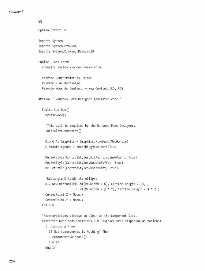
Chapter 5
224
VB
Option Strict On
Imports System
Imports System.Drawing
Imports System.Drawing.Drawing2D
Public Class Form1
Inherits System.Windows.Forms.Form
Private CenterPoint As PointF
Private R As Rectangle
Private Moon As Centroid = New Centroid(50, 50)
#Region " Windows Form Designer generated code "
Public Sub New()
MyBase.New()
'This call is required by the Windows Form Designer.
InitializeComponent()
Dim G As Graphics = Graphics.FromHwnd(Me.Handle)
G.SmoothingMode = SmoothingMode.AntiAlias
Me.SetStyle(ControlStyles.AllPaintingInWmPaint, True)
Me.SetStyle(ControlStyles.DoubleBuffer, True)
Me.SetStyle(ControlStyles.UserPaint, True)
'Rectangle R holds the ellipse
R = New Rectangle(CInt(Me.Width / 6), CInt(Me.Height / 6), _
CInt(Me.Width / 3 * 2), CInt(Me.Height / 3 * 2))
CenterPoint.X = Moon.X
CenterPoint.Y = Moon.Y
End Sub
'Form overrides dispose to clean up the component list.
Protected Overloads Overrides Sub Dispose(ByVal disposing As Boolean)
If disposing Then
If Not (components Is Nothing) Then
components.Dispose()
End If
End If
035c05.fm Page 224 Sunday, May 19, 2002 4:54 PM

Advanced Graphics
225225
MyBase.Dispose(disposing)
End Sub
'Required by the Windows Form Designer
Private components As System.ComponentModel.IContainer
'NOTE: The following procedure is required by the Windows Form Designer
'It can be modified using the Windows Form Designer.
'Do not modify it using the code editor.
<System.Diagnostics.DebuggerStepThrough()> Private Sub InitializeComponent()
'
'Form1
'
Me.AutoScaleBaseSize = New System.Drawing.Size(5, 13)
Me.ClientSize = New System.Drawing.Size(292, 273)
Me.Name = "Form1"
Me.StartPosition = System.Windows.Forms.FormStartPosition.CenterScreen
Me.Text = "Moon Over Mars"
End Sub
#End Region
Private Sub Form1_Load(ByVal sender As System.Object, _
ByVal e As System.EventArgs) Handles MyBase.Load
End Sub
Protected Overrides Sub OnPaint(ByVal e As PaintEventArgs)
Dim path As GraphicsPath = New GraphicsPath()
path.AddEllipse(R)
' Use the path to construct a path gradient brush.
Dim B As PathGradientBrush = New PathGradientBrush(path)
B.CenterColor = Color.Aqua
B.CenterPoint = CenterPoint
Dim c() As Color = {Color.Red}
B.SurroundColors = c
' Fill the path with the path gradient brush.
e.Graphics.FillPath(B, path)
Moon.Draw(e.Graphics)
End Sub
035c05.fm Page 225 Sunday, May 19, 2002 4:54 PM

Chapter 5
226
Public Sub GetCoord(ByVal sender As Object, _
ByVal e As System.Windows.Forms.MouseEventArgs) _
Handles MyBase.MouseMove
Me.Invalidate(Moon.Rect)
If Moon.Relocate(e) Then
CenterPoint = Moon.Center
'Redraw the centroid
Me.Invalidate(Moon.Rect)
'Redraw the main ellipse
Me.Invalidate(R)
End If
End Sub
End Class
This form’s code sets up the painting parameters so redrawing the form
will be very fast. It also draws a large red circle on the form that is filled with a PathGradientBrush. This brush has its center defined by the center of the moon. The moon is, of course, the object constructed by the new class you made.
You can move the moon by pressing the left mouse key while inside the moon boundary and dragging the moon to another position. While you are dragging the moon, the centroid of the PathGradientBrush is changed and the large circle is repainted to reflect this. The effect you get is a reflection of the satellite object on the stationary object.
Compile and run the program. Figure 5-9 shows the form as it first comes up.
Figure 5-9. Starting position of the centroid example
035c05.fm Page 226 Sunday, May 19, 2002 4:54 PM
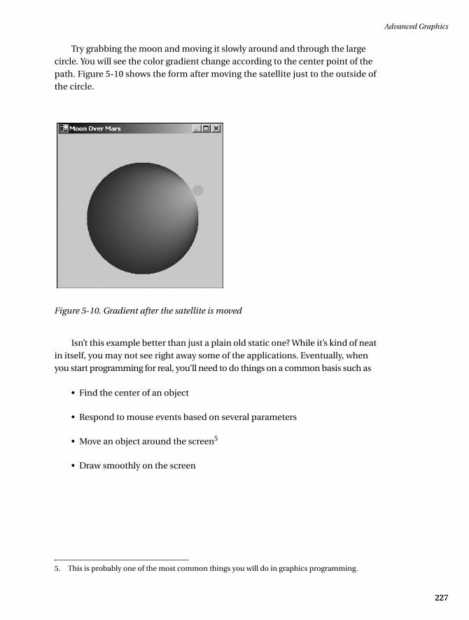
Advanced Graphics
227227
Try grabbing the moon and moving it slowly around and through the large circle. You will see the color gradient change according to the center point of the path. Figure 5-10 shows the form after moving the satellite just to the outside of the circle.
Figure 5-10. Gradient after the satellite is moved
Isn’t this example better than just a plain old static one? While it’s kind of neat in itself, you may not see right away some of the applications. Eventually, when you start programming for real, you’ll need to do things on a common basis such as
• Find the center of an object
• Respond to mouse events based on several parameters
• Move an object around the screen5
• Draw smoothly on the screen
5. This is probably one of the most common things you will do in graphics programming.
035c05.fm Page 227 Sunday, May 19, 2002 4:54 PM
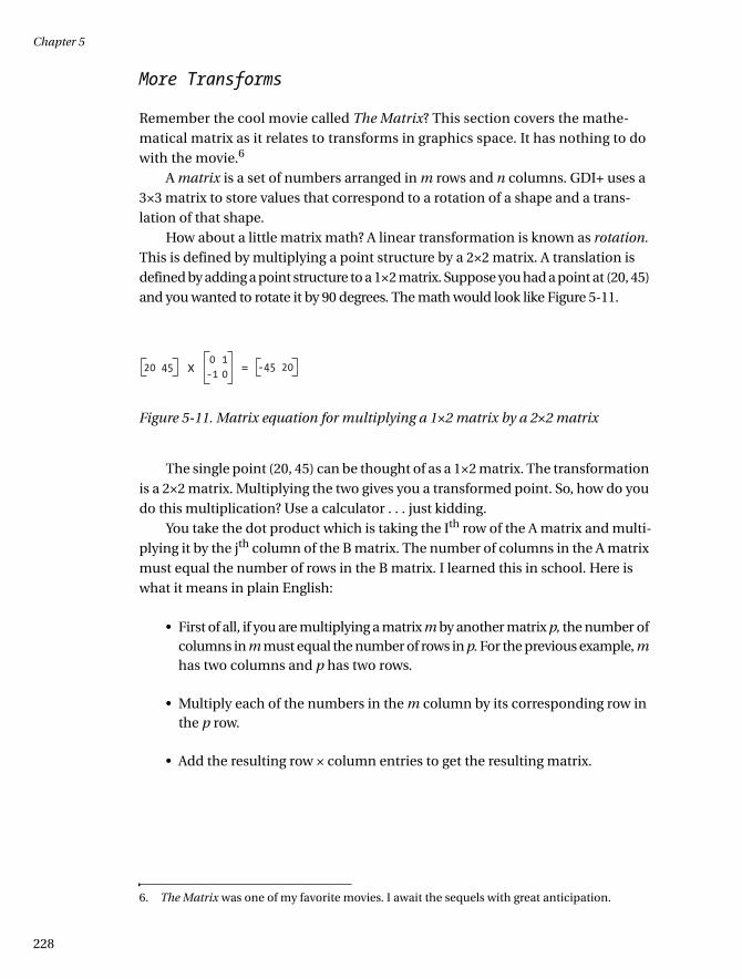
Chapter 5
228
More Transforms
Remember the cool movie called The Matrix? This section covers the mathe-matical matrix as it relates to transforms in graphics space. It has nothing to do with the movie.6
A matrix is a set of numbers arranged in m rows and n columns. GDI+ uses a 3×3 matrix to store values that correspond to a rotation of a shape and a trans-lation of that shape.
How about a little matrix math? A linear transformation is known as rotation. This is defined by multiplying a point structure by a 2×2 matrix. A translation is defined by adding a point structure to a 1×2 matrix. Suppose you had a point at (20, 45) and you wanted to rotate it by 90 degrees. The math would look like Figure 5-11.
Figure 5-11. Matrix equation for multiplying a 1×2 matrix by a 2×2 matrix
The single point (20, 45) can be thought of as a 1×2 matrix. The transformation is a 2×2 matrix. Multiplying the two gives you a transformed point. So, how do you do this multiplication? Use a calculator . . . just kidding.
You take the dot product which is taking the Ith row of the A matrix and multi-plying it by the jth column of the B matrix. The number of columns in the A matrix must equal the number of rows in the B matrix. I learned this in school. Here is what it means in plain English:
• First of all, if you are multiplying a matrix m by another matrix p, the number of columns in m must equal the number of rows in p. For the previous example, m has two columns and p has two rows.
• Multiply each of the numbers in the m column by its corresponding row in the p row.
• Add the resulting row × column entries to get the resulting matrix.
6. The Matrix was one of my favorite movies. I await the sequels with great anticipation.
20 450-1
10x = -45 20
035c05.fm Page 228 Thursday, May 23, 2002 5:15 PM
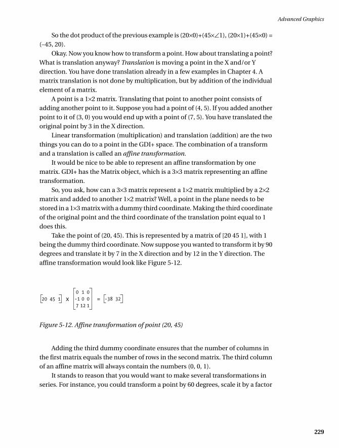
Advanced Graphics
229229
So the dot product of the previous example is (20×0)+(45×∠1), (20×1)+(45×0) = (–45, 20).
Okay. Now you know how to transform a point. How about translating a point? What is translation anyway? Translation is moving a point in the X and/or Y direction. You have done translation already in a few examples in Chapter 4. A matrix translation is not done by multiplication, but by addition of the individual element of a matrix.
A point is a 1×2 matrix. Translating that point to another point consists of adding another point to it. Suppose you had a point of (4, 5). If you added another point to it of (3, 0) you would end up with a point of (7, 5). You have translated the original point by 3 in the X direction.
Linear transformation (multiplication) and translation (addition) are the two things you can do to a point in the GDI+ space. The combination of a transform and a translation is called an affine transformation.
It would be nice to be able to represent an affine transformation by one matrix. GDI+ has the Matrix object, which is a 3×3 matrix representing an affine
transformation.So, you ask, how can a 3×3 matrix represent a 1×2 matrix multiplied by a 2×2
matrix and added to another 1×2 matrix? Well, a point in the plane needs to be stored in a 1×3 matrix with a dummy third coordinate. Making the third coordinate of the original point and the third coordinate of the translation point equal to 1 does this.
Take the point of (20, 45). This is represented by a matrix of [20 45 1], with 1 being the dummy third coordinate. Now suppose you wanted to transform it by 90 degrees and translate it by 7 in the X direction and by 12 in the Y direction. The affine transformation would look like Figure 5-12.
Figure 5-12. Affine transformation of point (20, 45)
Adding the third dummy coordinate ensures that the number of columns in the first matrix equals the number of rows in the second matrix. The third column of an affine matrix will always contain the numbers (0, 0, 1).
It stands to reason that you would want to make several transformations in series. For instance, you could transform a point by 60 degrees, scale it by a factor
20 45 10-17
1012
001
x = -38 32
035c05.fm Page 229 Thursday, May 23, 2002 5:15 PM
Chapter 5
230
of 3 in the Y direction, and then translate it by 32 in the X direction. This sequence of transformation can all be multiplied together to make a singe 3×3 matrix. What this means is that a sequence of transformations can also be stored in the Matrix object.
The Matrix class has several methods that allow you to do certain things to a point structure. Some of these methods are as follows:
• Multiply
• Rotate
• RotateAt
• Scale
• Shear
• TransformVectors
• TranslatePoints
I bet you thought you would have to do this matrix math yourself. The matrix math I have shown you only touches on the subject of linear algebra. I feel that it is good, however, to know something about what is going on behind the scenes.
The TransformVectors method applies the 3×3 matrix multiply to affect only the transform. Remember, a transform consists of rotation and scaling, not trans-lation. It does this by ignoring the third coordinate. The TransformPoints method applies the 3×3 matrix multiply to affect both a transform and translation of a point. Consider the following example, which applies an affine transform to sim-ulate the formula shown in Figure 5-12. This example transforms the point (20, 45) by 90 degrees and translates it by 7 in the X direction and 12 in the Y direction.
Create a new console application, either in VB or C#. Mine is called Matrix. Once you have created this application, set a reference in the Solution Explorer to System.Drawing. You will need this so you can import the System.Drawing and System.Drawing.Drawing2d namespaces. Listing 5-8 shows the code for this example.
Listing 5-8a. C# Code Showing an Affine Transform
using System;
using System.Drawing;
using System.Drawing.Drawing2D;
namespace Matrix_c
{
035c05.fm Page 230 Sunday, May 19, 2002 4:54 PM

Advanced Graphics
231231
class Class1
{
[STAThread]
static void Main(string[] args)
{
Matrix m = new Matrix();
m.Rotate(90, MatrixOrder.Append);
m.Translate(7, 12, MatrixOrder.Append);
Point[] p = {new Point(20, 45)};
Console.WriteLine(p.GetValue(0).ToString());
m.TransformPoints(p);
Console.WriteLine(p.GetValue(0).ToString());
Console.ReadLine();
}
}
}
Listing 5-8b. VB Code Showing an Affine Transformation
Option Strict On
Imports System.Drawing
Imports System.Drawing.Drawing2D
Module Module1
Sub Main()
Dim m As Matrix = New Matrix()
m.Rotate(90, MatrixOrder.Append)
m.Translate(7, 12, MatrixOrder.Append)
Dim p() As Point = {New Point(20, 45)}
Console.WriteLine(p.GetValue(0).ToString())
m.TransformPoints(p)
Console.WriteLine(p.GetValue(0).ToString())
Console.ReadLine()
End Sub
End Module
The first thing you do is make a matrix whose elements are set to rotate a point by 90 degrees and translate it by (7, 12). Once this is done, you write out the original points to the screen, tell the Matrix object to transform the points, and write out the results of the transformation. The results of running this example are as follows:
035c05.fm Page 231 Sunday, May 19, 2002 4:54 PM

Chapter 5
232
{X=20,Y=45}
{X=-38,Y=32}
No need for any math on your part. So now you know about matrix math and the Matrix class. What can you do with it? The following list details some of the classes that use the Matrix object:
• Pen.Transform
• Pen.MultiplyTransform
• Graphics.MultiplyTransform
• Graphics.Transform
• GraphicsPath.Flatten
• GraphicsPath.GetBounds
• GraphicsPath.Warp
• GraphicsPath.Widen
• LinearGradientBrush.Transform
• LinearGradientBrush.MultiplyTransform
• PathGradientBrush.Transform
• PathGradientBrush.MultiplyTransform
• TextureBrush.Transform
• TextureBrush.MultiplyTransform
• Region.Transform
How about another example showing how to use a Matrix object in a drawing situation? Open up a new project in either VB or C#. Mine is called MatrixDraw.
Place a vertical scroll bar on the right side of the form and call it “xlate”. Place a horizontal scroll bar at the bottom of the form and call it “rotate”. Your screen should look like the one shown in Figure 5-13.
035c05.fm Page 232 Sunday, May 19, 2002 4:54 PM

Advanced Graphics
233233
Figure 5-13. MatrixDraw form setup
Next, double-click each of the scroll bars to get the event handler generated for you. The default handler is okay here.
Go into the code pane and enter the code from Listing 5-9. The VB code includes only the constructor code from the wizard-generated code. The rest of the wizard code is not changed, so I did not include it here. The C# code does not include any of the wizard-generated code.
Listing 5-9a. C# Code for the MatrixDraw Example
using System;
using System.Drawing;
using System.Drawing.Drawing2D;
using System.Collections;
using System.ComponentModel;
using System.Windows.Forms;
using System.Data;
namespace MatrixDraw_c
{
public class Form1 : System.Windows.Forms.Form
{
internal System.Windows.Forms.HScrollBar rotate;
internal System.Windows.Forms.VScrollBar xlate;
/// <summary>
/// Required designer variable.
/// </summary>
035c05.fm Page 233 Sunday, May 19, 2002 4:54 PM

Chapter 5
234
private System.ComponentModel.Container components = null;
int XlateY;
float Angle;
Rectangle DrawingRect = new Rectangle(25, 25, 225, 225);
public Form1()
{
//
// Required for Windows Form Designer support
//
InitializeComponent();
Angle = 0;
XlateY = 0;
xlate.Minimum = -50;
xlate.Maximum = 50;
xlate.SmallChange = 1;
xlate.LargeChange = 5;
xlate.Value = 0;
rotate.Minimum = -180;
rotate.Maximum = 180;
rotate.SmallChange = 1;
rotate.LargeChange = 10;
rotate.Value = 0;
this.SetStyle(ControlStyles.AllPaintingInWmPaint, true);
this.SetStyle(ControlStyles.DoubleBuffer, true);
this.SetStyle(ControlStyles.UserPaint, true);
}
/// <summary>
/// Clean up any resources being used.
/// </summary>
protected override void Dispose( bool disposing )
{
if( disposing )
{
if (components != null)
{
components.Dispose();
}
}
base.Dispose( disposing );
}
035c05.fm Page 234 Sunday, May 19, 2002 4:54 PM

Advanced Graphics
235235
#region Windows Form Designer generated code
…
…
#end region
/// <summary>
/// The main entry point for the application.
/// </summary>
[STAThread]
static void Main()
{
Application.Run(new Form1());
}
private void Form1_Load(object sender, System.EventArgs e)
{
}
protected override void OnPaint(PaintEventArgs e)
{
Graphics G = e.Graphics;
G.SmoothingMode = SmoothingMode.AntiAlias;
// Create a graphics path, add a rectangle, set colors
GraphicsPath Path = new GraphicsPath();
Path.AddRectangle(new Rectangle(75, 100, 100, 75));
PointF[] Pts = Path.PathPoints;
PathGradientBrush B = new PathGradientBrush(Pts);
B.CenterColor = Color.Aqua;
Color[] SColor = {Color.Blue};
B.SurroundColors = SColor;
//We will translate the brush! NOT the rectangle!
Matrix m = new Matrix();
m.Translate(0, XlateY, MatrixOrder.Append);
m.RotateAt(Angle, B.CenterPoint, MatrixOrder.Append);
B.MultiplyTransform(m, MatrixOrder.Append);
G.FillRectangle(B, DrawingRect);
m.Dispose();
B.Dispose();
Path.Dispose();
}
035c05.fm Page 235 Sunday, May 19, 2002 4:54 PM

Chapter 5
236
private void xlate_Scroll(object sender,
System.Windows.Forms.ScrollEventArgs e)
{
XlateY = xlate.Value;
this.Invalidate(DrawingRect);
}
private void rotate_Scroll(object sender,
System.Windows.Forms.ScrollEventArgs e)
{
Angle = rotate.Value;
this.Invalidate(DrawingRect);
}
}
}
Listing 5-9b. VB Code for the MatrixDraw Example
Option Strict On
Imports System.Drawing
Imports System.Drawing.Drawing2D
Public Class Form1
Inherits System.Windows.Forms.Form
Dim XlateY As Int32
Dim Angle As Single
Dim DrawingRect As Rectangle = New Rectangle(25, 25, 225, 225)
#Region " Windows Form Designer generated code "
Public Sub New()
MyBase.New()
'This call is required by the Windows Form Designer.
InitializeComponent()
Angle = 0
Xlatey = 0
xlate.Minimum = -50
xlate.Maximum = 50
xlate.SmallChange = 1
xlate.LargeChange = 5
xlate.Value = 0
035c05.fm Page 236 Sunday, May 19, 2002 4:54 PM

Advanced Graphics
237237
rotate.Minimum = -180
rotate.Maximum = 180
rotate.SmallChange = 1
rotate.LargeChange = 10
rotate.Value = 0
Me.SetStyle(ControlStyles.AllPaintingInWmPaint, True)
Me.SetStyle(ControlStyles.DoubleBuffer, True)
Me.SetStyle(ControlStyles.UserPaint, True)
End Sub
…
…
#End Region
Private Sub Form1_Load(ByVal sender As System.Object, _
ByVal e As System.EventArgs) _
Handles MyBase.Load
End Sub
Protected Overrides Sub OnPaint(ByVal e As PaintEventArgs)
Dim G As Graphics = e.Graphics
G.SmoothingMode = SmoothingMode.AntiAlias
' Create a graphics path, add a rectangle, set colors
Dim Path As New GraphicsPath()
Path.AddRectangle(New Rectangle(75, 100, 100, 75))
Dim Pts As PointF() = Path.PathPoints
Dim B As New PathGradientBrush(Pts)
B.CenterColor = Color.Aqua
Dim SColor As Color() = {Color.Blue}
B.SurroundColors = SColor
'We will translate the brush! NOT the rectangle!
Dim m As New Matrix()
m.Translate(0, Xlatey, MatrixOrder.Append)
m.RotateAt(Angle, B.CenterPoint, MatrixOrder.Append)
B.MultiplyTransform(m, MatrixOrder.Append)
G.FillRectangle(B, DrawingRect)
035c05.fm Page 237 Sunday, May 19, 2002 4:54 PM

Chapter 5
238
m.Dispose()
B.Dispose()
Path.Dispose()
End Sub
Private Sub xlate_Scroll(ByVal sender As System.Object, _
ByVal e As System.Windows.Forms.ScrollEventArgs) _
Handles xlate.Scroll
Xlatey = xlate.Value
Me.Invalidate(DrawingRect)
End Sub
Private Sub rotate_Scroll(ByVal sender As System.Object, _
ByVal e As System.Windows.Forms.ScrollEventArgs) _
Handles rotate.Scroll
Angle = rotate.Value
Me.Invalidate(DrawingRect)
End Sub
End Class
Compile and run the program. You should get a screen like the one shown in Figure 5-14.
Figure 5-14. MatrixDraw start-up screen
035c05.fm Page 238 Sunday, May 19, 2002 4:54 PM
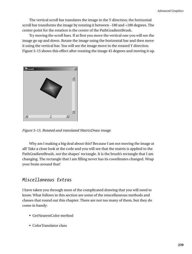
Advanced Graphics
239239
The vertical scroll bar translates the image in the Y direction; the horizontal scroll bar transforms the image by rotating it between –180 and +180 degrees. The center point for the rotation is the center of the PathGradientBrush.
Try moving the scroll bars. If at first you move the vertical one you will see the image go up and down. Rotate the image using the horizontal bar and then move it using the vertical bar. You will see the image move in the rotated Y direction. Figure 5-15 shows this effect after rotating the image 45 degrees and moving it up.
Figure 5-15. Rotated and translated MatrixDraw image
Why am I making a big deal about this? Because I am not moving the image at all! Take a close look at the code and you will see that the matrix is applied to the PathGradientBrush, not the shapes’ rectangle. It is the brush’s rectangle that I am changing. The rectangle that I am filling never has its coordinates changed. Wrap your brain around that!
Miscellaneous Extras
I have taken you through most of the complicated drawing that you will need to know. What follows in this section are some of the miscellaneous methods and classes that round out this chapter. There are not too many of them, but they do come in handy:
• GetNearestColor method
• ColorTranslator class
035c05.fm Page 239 Sunday, May 19, 2002 4:54 PM

Chapter 5
240
• GraphicsPathIterator
• RegionData
The GetNearestColor method returns a Color structure that is the nearest system color to the color that you have specified. For instance, you might specify a color like this:
Color MyColor = Color.FromArgb( 255, 100, 100 , 100);
Now suppose you want to get the next color up that was a known system color. You would do this:
Color ActualColor = e.Graphics.GetNearestColor(MyColor);
Translating Colors
The ColorTranslator class has the following public methods:
• FromHtml
• FromOle
• FromWin32
• ToHtml
• ToOle
• ToWin32
As you can probably guess, this class allows you to go from one type of color definition to another. When would you use this? How about when you are accessing a COM object using the COM Interop with a .NET class? This COM object hands you a color that it wants your .NET client to use in rendering a form. The ColorTranslator.FromOle method would be used here. This is because colors in the COM world are defined as OLECOLOR.
Tracing a Path
Okay, you have generated this complicated path made up of all kinds of shapes. Now you want to traverse that path. To do this, you use the GraphicsPathIterator
035c05.fm Page 240 Sunday, May 19, 2002 4:54 PM
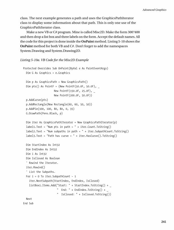
Advanced Graphics
241241
class. The next example generates a path and uses the GraphicsPathIterator class to display some information about that path. This is only one use of the GraphicsPathIterator class.
Make a new VB or C# program. Mine is called Misc2D. Make the form 300?400 and then drop a list box and three labels on the form. Accept the default names. All the code for this project is done inside the OnPaint method. Listing 5-10 shows the OnPaint method for both VB and C#. Don’t forget to add the namespaces System.Drawing and System.Drawing2D.
Listing 5-10a. VB Code for the Misc2D Example
Protected Overrides Sub OnPaint(ByVal e As PaintEventArgs)
Dim G As Graphics = e.Graphics
Dim p As GraphicsPath = New GraphicsPath()
Dim pts() As PointF = {New PointF(50.0F, 50.0F), _
New PointF(150.0F, 25.0F), _
New PointF(200.0F, 50.0F)}
p.AddCurve(pts)
p.AddRectangle(New Rectangle(60, 60, 50, 50))
p.AddPie(100, 100, 80, 80, 0, 35)
G.DrawPath(Pens.Black, p)
Dim iter As GraphicsPathIterator = New GraphicsPathIterator(p)
label1.Text = "Num pts in path = " + iter.Count.ToString()
label2.Text = "Num subpaths in path = " + iter.SubpathCount.ToString()
label3.Text = "Path has curve = " + iter.HasCurve().ToString()
Dim StartIndex As Int32
Dim EndIndex As Int32
Dim i As Int32
Dim IsClosed As Boolean
' Rewind the Iterator.
iter.Rewind()
' List the Subpaths.
For i = 0 To iter.SubpathCount - 1
iter.NextSubpath(StartIndex, EndIndex, IsClosed)
listBox1.Items.Add("Start: " + StartIndex.ToString() + _
" End: " + EndIndex.ToString() + _
" IsClosed: " + IsClosed.ToString())
Next
End Sub
035c05.fm Page 241 Sunday, May 19, 2002 4:54 PM

Chapter 5
242
Listing 5-10b. C# Code for the Misc2D Example
protected override void OnPaint(PaintEventArgs e)
{
Graphics G = e.Graphics;
GraphicsPath p = new GraphicsPath();
PointF[] pts = { new PointF(50, 50),
new PointF(150, 25),
new PointF(200, 50)};
p.AddCurve(pts);
p.AddRectangle(new Rectangle(60, 60, 50, 50));
p.AddPie(100, 100, 80, 80, 0, 35);
G.DrawPath(Pens.Black,p);
GraphicsPathIterator iter = new GraphicsPathIterator(p);
label1.Text = "Num pts in path = " + iter.Count.ToString();
label2.Text = "Num subpaths in path = " + iter.SubpathCount.ToString();
label3.Text = "Path has curve = " + iter.HasCurve().ToString();
int StartIndex;
int EndIndex;
int i;
bool IsClosed;
// Rewind the Iterator.
iter.Rewind();
// List the Subpaths.
for(i=0;i<iter.SubpathCount;i++)
{
iter.NextSubpath(out StartIndex, out EndIndex, out IsClosed);
listBox1.Items.Add("Start: " + StartIndex.ToString() +
" End: " + EndIndex.ToString() +
" IsClosed: " + IsClosed.ToString());
}
}
Compile and run the program. Your output should match that shown in Figure 5-16.
035c05.fm Page 242 Sunday, May 19, 2002 4:54 PM

Advanced Graphics
243243
Figure 5-16. Result of the Misc2D example
As you can see from this example, you generate a GraphicsPath that is made up of three shapes. Each of these shapes is referred to as a subpath. You will also see that the iterator tells you if the shape is closed and what the start and end indexes are.
There is quite a bit more you can do with the GraphicsPathIterator class. I have shown you just a little here. Walking a path is something you will probably need to do at some time. I suggest you familiarize yourself more with this class via the MSDN documents.
Looking at Your Region’s Data
Remember the clipping regions from Chapter 4? You used them to encapsulate drawing to a particular area of the screen. You have also used regions in this chapter to speed up the drawing process by invalidating regions of the screen.
You can get information about any region that you have created by using the RegionData class. This class has one member: Data. This member returns an array of bytes that describe the region. The following snippet of code demonstrates how to use it:
035c05.fm Page 243 Sunday, May 19, 2002 4:54 PM

Chapter 5
244
Rectangle regionRect = new Rectangle(20, 20, 100, 100);
Region myRegion = new Region(regionRect);
RegionData Rd = myRegion.GetRegionData();
int RdLength = Rd.Data.Length;
You can keep the RegionData object in memory, fiddle with the data itself, and create a new region from this data.
Summary
Well, you have learned quite a bit in this chapter. In Chapter 4, I showed you some of the basic drawing functionality. This chapter extended that by demonstrating more of the depth of GDI+. Here is a summary of what you learned:
• Pen and brush end caps: These end caps represent a new way to change the shape of a line.
• HatchBrush: This brush is made up of repeating hatch patterns.
• Alpha blend: This is about transparency in shapes, colors, and images.
• Gamma correction: This refers to the brightness and contrast of images and how to change them.
• Flicker: I spent quite a bit of time on how to paint with no flicker, including using the ControlStyles enumeration and invalidating regions.
• LinearGradientBrush: This brush is made up of colors that change gradually from a start color to an end color in a linear fashion.
• PathGradientBrush: This brush is made up of colors that change from a center point out to another color at the edges of a shape. I supplied examples on wrapping and changing the centroid of a gradient.
• Transforms: I covered the 3×3 matrix called an affine transformation. This allows you to rotate, scale, and translate an image or a brush.
• GraphicsPathIterator: This class allows you to walk a graphics path and find information about that path.
035c05.fm Page 244 Sunday, May 19, 2002 4:54 PM

Advanced Graphics
245245
This chapter contained a lot of information to digest. Hopefully, I have provided you with enough examples to make it clear not only how to use some of this func-tionality, but also how you could use it.
The next chapter is about imaging. This is where you will learn about bitmaps, JPEG files, and so forth, and how to manipulate them. Remember the satellite over the planet example? The next chapter will show you how to speed up this program even more.
035c05.fm Page 245 Sunday, May 19, 2002 4:54 PM