ge control catalog - section 6: iec manual motor starters
TRANSCRIPT

www.geindustrial.com Control Catalog 6-1
IEC Manual Motor Starters
Rev. 4/16Prices and data subject tochange without notice
Section 6
Overview.........................................................................................................6-2Selection Guide............................................................................................6-5Accessories – Front Mounted ...............................................................6-7Accessories – Side Mounted .................................................................6-7Accessories – Group Mounted .............................................................6-9Accessories – External Handle Operators ...................................6-10Accessories – Other................................................................................6-10Accessories – Integrated Starter Components .........................6-11Enclosures and Enclosure Accessories .........................................6-13Integrated with Contactor, Open, AC Operated Contactors, Standard Interruption Capacity ...........................6-15
Integrated with Contactor, Open, DC Operated Contactors, Standard Interruption Capacity ...........................6-16
Integrated with Contactor, Open, AC Operated Contactors, High Interruption Capacity.....................................6-17
Integrated with Contactor, Open, DC Operated Contactors, High Interruption Capacity.....................................6-18
Integrated with Contactor, Factory Installed Accessories..............................................................................................6-19
Enclosed, Non-metal Enclosures, Standard Interruption Capacity .....................................................6-20
Enclosed, Factory Installed Accessories .......................................6-21Enclosed, Metal Enclosures, High Interruption Capacity ......6-22Enclosed, Factory Installed Accessories .......................................6-23Integrated with Contactor, Enclosed, AC Operated Contactors, High Interruption Capacity ........6-24
Integrated with Contactor, Enclosed, DC Operated Contactors, High Interruption Capacity ........6-26
Integrated with Contactors, Factory Installed Accessories .........................................................6-28
Outline Drawings .....................................................................................6-30Wiring Diagrams – Accessories ........................................................6-42Short Circuit Current Rating, Rating Breaking Capacity .......6-44Type 2 Short Circuit Rating, Individual Group and Combination Starters..........................................................................6-45
Specifications.............................................................................................6-46Time Current Curves...............................................................................6-47

www.geindustrial.com Rev. 4/16Prices and data subject tochange without notice
Control Catalog6-2
IEC Manual Motor StartersOverview
Section 6IEC Manual Motor Starters
GE’s Surion IEC motor starters are compact and reliable. Theyare flexible, quick in installation and available in 45mm and55mm widths. The GPS1 line spans current ranges from 0.1A to 32A for use with motors up to 30hp at 600V. The GPS2 seriesextends this current range to 63A for use with motors up to andincluding 50 hp.
Surion GPS1 starters are available in two versions. The GPS1BS_ _series, with a toggle operator, is suitable for individual and groupinstallations. Short circuit interruption capacity ranges up to100kA @ 240V, 50kA @ 480V and 10kA @ 600V for individualinstallations and 100 kA @ 240V, 65kA @ 480V and 25kA @ 600V for group installations. The GPS1BH_ _ series, with arotary operator, carries equivalent or higher short circuit ratingsand is also suitable for combination installations with a short circuit interruption rating of 50kA for 277/480V and below. TheGPS2BH_ _ series also features a rotary operator and is suitablefor all three types of installations. Complete short circuit ratingsare listed on page 6-44.
All Surion IEC motor starters include the following features:—45mm width up to 32 amps, 55mm width rated to 63 amps—Three position operator: OFF-TRIP-ON—Padlockable in the OFF position—Class 10 overload trip characteristics—Ambient compensated –20°C to +60°C—Single-phase sensitivity—Anti tamper cover over current adjustment dial—Trip test—Complete range of common accessories—Finger-safe terminals—Pz 2 slotted/combination screws—35mm DIN rail mounting
Surion is global. It is available around the world in the same form,with the same product number, with both IEC and US markings, making international applications simple and sure.
Surion starters are flexible in application. They not only complywith the IEC installation requirements, such as Disconnects, MainSwitch, Emergency Off and Maintenance Service Switch, theymay also be used in a wide variety of US applications. Surionstarters may be used as—Manual starters—Group installed starters—Combination starter – manual self-protected (Type E)GPS1BH* and GPS2BH* versions
—Combination starter – with C-2000 contactor or mini-contactor
A complete range of accessories extends the application flexibili-ty of the line. Front and side mounted auxiliary contacts, alarmcontacts, short circuit reset/indicator alarm, shunt trip andundervoltage release (with or without early make auxiliary con-tacts) allow Surion to easily adapt to your specific needs. Inputbusbars further speed and simplify group installations.Enclosures and accessories extend flexibility. Bases, links andother components allow you to assemble integrated starters.
45 mm Standard Interruption Capacity
55 mm High Interruption Capacity
Integrated With Contactor
Accessories

www.geindustrial.com Control Catalog 6-3
IEC Manual Motor StartersOverview
Rev. 4/16Prices and data subject tochange without notice
Section 6IEC Manual Motor Starters
Individual Installation
Manual motor starters (UL-508, Part III) are devices that provide a means of controlling (switching on and off) a motor. UL-508allows a manual motor starter to be applied in individual installa-tions between a branch short circuit protection device (circuitbreaker or fuse) and a motor (see Figure 1A).
The UL, cUL listing allows Surion starters to be utilized in installa-tions up to 600 volts. Short circuit ratings are listed in the tableson page 6-44. GE’s type MC or CL contactors may be used inseries with the motor starter for remote motor operation asshown in Figure 1B. Contactors must not be applied at ratingsabove their nameplate HP/current ratings.
Group Installation
Manual motor starters may be applied in group applications perArticle 430-53 of the National Electrical Code. Refer to the NECfor specific requirements. Group installations are used when multi-ple loads are tapped off of a single branch short circuit protectivedevice (circuit breaker or fuse). A manual motor starter is placedbetween the branch disconnect and each motor (see Figure 2A).
The UL, cUL listing allows starters to be utilized in installations up to600 volts. Short circuit ratings are listed in the tables on page 6-44.GE’s type MC or CL contactors may be used in series with the motorstarter for remote motor operation (see Figure 2B). Contactors mustnot be applied at ratings above their nameplate HP/current ratings.
or
Figure 1A
or
Figure 2A
or
Figure 1B
or
Figure 2B

www.geindustrial.com Rev. 4/16Prices and data subject tochange without notice
Control Catalog6-4
IEC Manual Motor StartersOverview
Section 6
Combination StartersSurion GPS1BH* and GPS2BH* Manual Motor Starters may be used as combination starters (UL508 Part IV) and have beenevaluated by UL as manual self-protected combination motorstarters (Type E) for applications 277/480 and below. They providecoordinated branch circuit short circuit protection consistent withSection 430-52(c) (6) of the NEC; a disconnecting means consis-tent with Section 430-109 (a) (5); a motor starter and coordinatedmotor overload protection (see Figure 3A). These starters may beused for controlling motors without additional upstream branchcircuit protection. They may be used in place of branch devices in motor circuits only. When used in panels with multiple motorcircuits, a main circuit disconnect is required in sight and within50 feet for the protection of service personnel.
Surion GPS1BH* and GPS2BH* Manual Self ProtectedCombination Starters may also be used with a contactor when a high number of operations are required or remote switching isdesired. A combination motor starter (see Figure 3B) is created bylinking the self-protected manual motor starter with an evaluatedcontactor that has been tested for the combination. All C-2000contactors and mini-contactors are suitable for use with Surionstarters which, when used in this configuration, are suitable ascombination motor starters. Using bases and links (see page 6-12) combination motor starters may be easily assembled bydistributors, OEM’s or end users. This integrated starter approachallows the user to service or replace the load switching means(contactor) and/or the interrupting/disconnecting means (Surionstarter) should the need arise.
For combination starter installations, the standards require ameans to differentiate between a short circuit and overload tripconditions. Surion delivers this means through the use of theShort Circuit Alarm Accessory GPAE11LLA (sold separately – seepage 6-7). This accessory provides specific indication of a shortcircuit trip condition and includes a manual reset. Add GPAPT1Eterminal cover to GPS1BH* for Type E and combination starterapplications.
Figure 3A
Figure 3B

www.geindustrial.com Control Catalog 6-5
IEC Manual Motor StartersSelection Guide
Rev. 4/16Prices and data subject tochange without notice
Section 6
Selection and PricingSurion comprises a complete range of compact, reliable motorstarters, rated from 0.1A to 63A, in 45mm and 55mm framewidths. It represents a motor protection system for switching andprotecting three-phase induction motors to 50hp at 600 volts.
Surion starters are available worldwide. They are specificallydesigned to deliver total connectivity with GE’s other IEC motorstarters and controls, and they can be combined with our MC andCL contactors to form integrated solutions.
A full complement of accessories create solutions for all types ofapplications. You can choose from frontal auxiliary and alarmcontacts, lateral auxiliary contacts, alarm/auxiliary and short circuit trip indicators, shunt trip, undervoltage release (with orwithout early make auxiliary contacts), enclosures, group busbars and more. You can also select assembled versions.
Product Number Selection InstructionsSelection of the starter depends on the actual motor full load current and service factor. For motors with service factor of 1.15or greater, use motor full load current to select the appropriatecurrent range. For motors with a service factor less than 1.15,multiply the normal full load current by .9 for the current setting.Single phase applications require all three overload legs to beenergized for proper operation. Use separate conductor to connect terminal T2 to L3. Connect power to L1 and L2 and apply load between T1 and T3.
Reference Publications Instructions: DEH-40111
45 mm Standard Interruption Capacity (Toggle)
45 mm High Interruption Capacity (Rotary)
55 mm High Interruption Capacity (Rotary)

www.geindustrial.com Rev. 4/16Prices and data subject tochange without notice
Control Catalog6-6
IEC Manual Motor StartersSelection Guide
Section 6
45 mm Standard Interruption Capacity (Toggle Operator)Individual or Group Installation, with or without C-2000 contactors or mini-contactorsFLA Three Phase Three Phase Three Phase Three Phase Single Phase Single Phase Instantaneous Adjustment Horsepower Horsepower Horsepower Horsepower Horsepower Horsepower Short Circuit Product List PriceRange @ 200-208V @ 220-240V @ 440-480V @ 575-600V @ 115V @ 230V Release Amps Number GO-10A2C
0.1-0.16 2.1 GPS1BSAA $88.000.16-0.25 3.3 GPS1BSAB $88.000.25-0.4 5.2 GPS1BSAC $88.000.4-0.63 8.2 GPS1BSAD $88.000.63-1.0 1/2 1/2 13 GPS1BSAE $100.001-1.6 1/4 1/3 3/4 3/4 1/10 20.8 GPS1BSAF $100.001.6-2.5 1/2 1/2 1 1 1/2 1/6 32.5 GPS1BSAG $100.002.5-4 3/4 3/4 2 3 1/8 1/3 52 GPS1BSAH $100.004-6.3 1 1 1/2 3 5 1/4 1/2 81.9 GPS1BSAJ $100.006.3-10 2 3 5 7 1/2 1/2 1 1/2 130 GPS1BSAK $100.009-13 3 3 7 1/2 10 1/2 2 169 GPS1BSAL $120.0011-16 3 5 10 10 1 2 208 GPS1BSAM $120.0014-20 5 5 10 15 1 1/2 3 260 GPS1BSAN $120.0019-25 7 1/2 7 1/2 15 20 2 3 325 GPS1BSAP $135.0024-32 10 10 20 30 2 5 416 GPS1BSAR $135.00
45 mm High Interruption Capacity (Rotary Operator)Individual, Group or Combination1, 2 Installation, with or without C-2000 contactors or mini-contactorsFLA Three Phase Three Phase Three Phase Three Phase Single Phase Single Phase Instantaneous Adjustment Horsepower Horsepower Horsepower Horsepower Horsepower Horsepower Short Circuit Product List PriceRange @ 200-208V @ 220-240V @ 440-480V @ 575-600V @ 115V @ 230V Release Amps Number GO-10A2C
0.1-0.16 2.1 GPS1BHAA $110.000.16-0.25 3.3 GPS1BHAB $110.000.25-0.4 5.2 GPS1BHAC $110.000.4-0.63 8.2 GPS1BHAD $110.000.63-1.0 1/2 1/2 13 GPS1BHAE $125.001-1.6 1/4 1/3 3/4 3/4 1/10 20.8 GPS1BHAF $125.001.6-2.5 1/2 1/2 1 1 1/2 1/6 32.5 GPS1BHAG $125.002.5-4 3/4 3/4 2 3 1/8 1/3 52 GPS1BHAH $125.004-6.3 1 1 1/2 3 5 1/4 1/2 81.9 GPS1BHAJ $125.006.3-10 2 3 5 7 1/2 1/2 1 1/2 130 GPS1BHAK $125.009-13 3 3 7 1/2 10 1/2 2 169 GPS1BHAL $150.0011-16 3 5 10 10 1 2 208 GPS1BHAM $150.0014-20 5 5 10 15 1 1/2 3 260 GPS1BHAN $150.0019-25 7 1/2 7 1/2 15 20 2 3 325 GPS1BHAP $165.0024-32 10 10 20 30 2 5 416 GPS1BHAR $165.00
55 mm High Interruption Capacity (Rotary Operator)Individual, Group or Combination2 Installation, with or without C-2000 contactors or mini-contactorsFLA Three Phase Three Phase Three Phase Three Phase Single Phase Single Phase Instantaneous Adjustment Horsepower Horsepower Horsepower Horsepower Horsepower Horsepower Short Circuit Product List PriceRange @ 200-208V @ 220-240V @ 440-480V @ 575-600V @ 115V @ 230V Release Amps Number GO-10A2C
6.3-10 2 3 5 7 1/2 1/2 1 1/2 130 GPS2BHAK $245.009-13 3 3 7 1/2 10 1/2 2 169 GPS2BHAL $245.0011-16 3 5 7 1/2 10 1 2 208 GPS2BHAM $245.0014-20 5 5 10 15 1 1/2 2 260 GPS2BHAN $245.0019-25 7 1/2 7 1/2 15 20 2 3 325 GPS2BHAP $245.0024-32 10 10 20 25 2 5 416 GPS2BHAR $245.0028-40 10 10 25 30 3 7 1/2 520 GPS2BHAS $275.0035-50 15 15 30 40 3 10 650 GPS2BHAT $275.0045-63 15 20 40 50 5 10 819 GPS2BHAU $302.00
1When using manual starters in combination starter applications, use short circuit reset/indicator accessory. For GPS1BH_ _starters add GPAPT1E terminal accessory. 2Maximum voltage for combination control is 277/480.
Product Number Selection InstructionsSelection of the starter depends on the actual motor full load current and service factor. For motors with service factor of 1.15 orgreater, use motor full load current to select the appropriate current range. For motors with a service factor less than 1.15, multiplythe normal full load current by .9 for the current setting. Single phase applications require all three overload legs to be energized forproper operation. Use separate conductor to connect terminal T2 to L3. Connect power to L1 and L2 and apply load between T1 and T3.

www.geindustrial.com Control Catalog
Terminal Identification and Wiring Diagrams:See page 6-42
6-7
IEC Manual Motor StartersAccessories
Rev. 4/16Prices and data subject tochange without notice
Section 6
Front Mounted (Internal) Accessories—Auxiliary and Alarm ContactsSnap away the dust cover(s) and up to two front mounted accessories slide into thestarter, increasing application flexibility without increasing width.
Mounting Contact Product List PriceAccessory Type For Use With Position Configuration Number GO-10A2C
Auxiliary Contact (Front Mount) GPS1*/GPS2* Left or right front 1NC GPAC01FBA $12.00Auxiliary Contact (Front Mount) GPS1*/GPS2* Left or right front 1NO GPAC10FBA $12.00Alarm Contact (Front Mount) GPS1*/GPS2* Right front 1NC GPAL01FRA $14.00Alarm Contact (Front Mount) GPS1*/GPS2* Right front 1NO GPAL10FRA $14.00Front Aux. Position Cover (Package of 10) GPS1*/GPS2* Left or right front N/A GPAC0VF1A $0.50
Side Mounted Accessories—Auxiliary and Alarm ContactsSnap on accessories - maximum of [(2) auxiliary contact blocks] or [(1) auxiliary contactblock plus (1) alarm/aux. block or (1) short circuit indicator] or [(1) alarm/auxiliary plus (1)short circuit indicator] left and (2) auxiliary contact blocks or (1) shunt trip or (1) under-voltage release right.
Mounting Contact Product List PriceAccessory Type For Use With Position Configuration Number GO-10A2C
Auxiliary Contact (Side Mount GPS1*/GPS2* Left 2NC GPAC02LLA1 $18.00Auxiliary Contact (Side Mount) GPS1*/GPS2* Left 1NO + 1NC GPAC11LLA1 $18.00Auxiliary Contact (Side Mount) GPS1*/GPS2* Left 2NO GPAC20LLA1 $18.00Auxiliary Contact (Side Mount) GPS1*/GPS2* Right 2NC GPAC02LRA1 $18.00Auxiliary Contact (Side Mount) GPS1*/GPS2* Right 1NO + 1NC GPAC11LRA1 $18.00Auxiliary Contact (Side Mount) GPS1*/GPS2* Right 2NO GPAC20LRA1 $18.00Alarm/Auxiliary Contact (Side Mount) GPS1*/GPS2* Left 1NC Alarm + 1NC Aux. GPAD0101LLA $24.00Alarm/Auxiliary Contact (Side Mount) GPS1*/GPS2* Left 1NC Alarm + 1NO Aux. GPAD0110LLA $24.00Alarm/Auxiliary Contact (Side Mount) GPS1*/GPS2* Left 1NO Alarm + 1NC Aux. GPAD1001LLA $24.00Alarm/Auxiliary Contact (Side Mount) GPS1*/GPS2* Left 1NO Alarm + 1NO Aux. GPAD1010LLA $24.00Short Circuit Alarm (Side Mount) GPS1*/GPS2* Left 1NO + 1NC GPAE11LLA2 $15.00
1GPS1BSAR and GPS1BHAR (24-32 FLA starters) can accept all accessory combinations noted above except thatonly one lateral auxiliary contact block may be used on this size.
2GPAE11LLA short circuit alarm may not be used with non-metallic enclosures due to reset button interference.
GPAC_ _FBAFront Mounted Auxiliary Contacts
GPAC_ _FRAFront Mounted Alarm Contacts
GPAC_ _LLA/GPAC_ _LRASide Mounted Auxiliary Contacts
GPAD_ _ _ _LLASide Mounted Alarm/Auxiliary Contact
GPAE11LLASide Mounted Short Circuit Alarm

www.geindustrial.com Rev. 4/16Prices and data subject tochange without notice
Control Catalog6-8
IEC Manual Motor StartersAccessories
Section 6
Side Mounted Accessories—Shunt TripSnap on accessories - maximum of (2) auxiliary contact blocks or (1) shunt trip or (1) undervoltage release right side.
Mounting Product List PriceAccessory Type For Use With Position Coil Voltage Number GO-10A2C
Shunt Trip GPS1*/GPS2* Right 24V 60/50 Hz GPASLRAA1 $48.00Shunt Trip GPS1*/GPS2* Right 48V 60 Hz GPASLRAAF $48.00Shunt Trip GPS1*/GPS2* Right 60V 60 Hz, 48V 50 Hz GPASLRAAG $48.00Shunt Trip GPS1*/GPS2* Right 120V 60 Hz, 110-127V 50 Hz GPASLRAAJ $48.00Shunt Trip GPS1*/GPS2* Right 208V 60 Hz GPASLRAAM $48.00Shunt Trip GPS1*/GPS2* Right 240V 60 Hz, 220V 50 Hz GPASLRAAN $48.00Shunt Trip GPS1*/GPS2* Right 277V 60 Hz, 240V 50 Hz GPASLRAAR $48.00Shunt Trip GPS1*/GPS2* Right 380/400V 50 Hz GPASLRAAU $48.00Shunt Trip GPS1*/GPS2* Right 460-480V 60 Hz, 415-440V 50 Hz GPASLRAAW $48.00Shunt Trip GPS1*/GPS2* Right 600V 60 Hz, 500V 50 Hz GPASLRAAY $48.00Shunt Trip GPS1*/GPS2* Right 24-60V DC GPASLRADD $48.00Shunt Trip GPS1*/GPS2* Right 110-240V DC GPASLRADJ $48.00De-energizes the controller when external signal is applied to shunt coil.
Side Mounted Accessories—Undervoltage ReleaseSnap on accessories - maximum of (2) auxiliary contact blocks or (1) shunt trip or (1) undervoltage release right side.
Mounting Product List PriceAccessory Type For Use With Position Coil Voltage Number GO-10A2C
Undervoltage Release GPS1*/GPS2* Right 24V 60 Hz GPAULRAAC $48.00Undervoltage Release GPS1*/GPS2* Right 24V 50 Hz GPAULRAAD $48.00Undervoltage Release GPS1*/GPS2* Right 48V 60 Hz GPAULRAAF $48.00Undervoltage Release GPS1*/GPS2* Right 48V 50 Hz GPAULRAAG $48.00Undervoltage Release GPS1*/GPS2* Right 120V 60Hz, 110-127V 50 Hz GPAULRAAJ $48.00Undervoltage Release GPS1*/GPS2* Right 208V 60 Hz GPAULRAAM $48.00Undervoltage Release GPS1*/GPS2* Right 240-260V 60 Hz, 220/230V 50 Hz GPAULRAAN $48.00Undervoltage Release GPS1*/GPS2* Right 277V 60 Hz, 240V 50 Hz GPAULRAAR $48.00Undervoltage Release GPS1*/GPS2* Right 380/400V 50 Hz GPAULRAAU $48.00Undervoltage Release GPS1*/GPS2* Right 460-480V 60 Hz, 415-440V 50 Hz GPAULRAAW $48.00Undervoltage Release GPS1*/GPS2* Right 600V 60 Hz, 500V 50 Hz GPAULRAAY $48.00Provides protection from low voltage conditions; requires 85-110% voltage across D1 and D2 prior to starting
motor; requires reset of starter upon undervoltage condition or loss of voltage.
Side Mounted Accessories—Undervoltage ReleaseSnap on accessories - maximum of (2) auxiliary contact blocks or (1) shunt trip or (1) undervoltage release right side.
Mounting Product List PriceAccessory Type For Use With Position Coil Voltage Number GO-10A2C
Undervoltage Release GPS1BS* Right 24V 60 Hz GPAU20LTAAC $66.00Undervoltage Release GPS1BS* Right 24V 50 Hz GPAU20LTAAD $66.00Undervoltage Release GPS1BS* Right 48V 60 Hz GPAU20LTAAF $66.00Undervoltage Release GPS1BS* Right 48V 50 Hz GPAU20LTAAG $66.00Undervoltage Release GPS1BS* Right 120V 60 Hz, 110-127V 50 Hz GPAU20LTAAJ $66.00Undervoltage Release GPS1BS* Right 208V 60 Hz GPAU20LTAAM $66.00Undervoltage Release GPS1BS* Right 240-260V 60 Hz, 220/230V 50 Hz GPAU20LTAAN $66.00Undervoltage Release GPS1BS* Right 277V 60 Hz, 240V 50 Hz GPAU20LTAAR $66.00Undervoltage Release GPS1BS* Right 380/400V 50 Hz GPAU20LTAAU $66.00Undervoltage Release GPS1BS* Right 460-480V 60 Hz, 415-440V 50 Hz GPAU20LTAAW $66.00Undervoltage Release GPS1BS* Right 600V 60 Hz, 500V 50 Hz GPAU20LTAAY $66.00With 2NO early make contacts (provides protection from low voltage conditions; early make contacts energize
release coil when operator is turned to ON position and voltage is 85-110% Ve; requires reset of starter uponundervoltage condition or loss of voltage)
Side Mounted Accessories—Undervoltage ReleaseSnap on accessories - maximum of (2) auxiliary contact blocks] or (1) shunt trip or (1) undervoltage release right side.
Mounting Product List PriceAccessory Type For Use With Position Coil Voltage Number GO-10A2C
Undervoltage Release GPS1BH*/GPS2BH* Right 24V 60 Hz GPAU20LCAAC $66.00Undervoltage Release GPS1BH*/GPS2BH* Right 24V 50 Hz GPAU20LCAAD $66.00Undervoltage Release GPS1BH*/GPS2BH* Right 48V 60 Hz GPAU20LCAAF $66.00Undervoltage Release GPS1BH*/GPS2BH* Right 48V 50 Hz GPAU20LCAAG $66.00Undervoltage Release GPS1BH*/GPS2BH* Right 120V 60 Hz, 110-127V 50 Hz GPAU20LCAAJ $66.00Undervoltage Release GPS1BH*/GPS2BH* Right 208V 60 Hz GPAU20LCAAM $66.00Undervoltage Release GPS1BH*/GPS2BH* Right 240-260V 60 Hz, 220/230V 50 Hz GPAU20LCAAN $66.00Undervoltage Release GPS1BH*/GPS2BH* Right 277V 60 Hz, 240V 50 Hz GPAU20LCAAR $66.00Undervoltage Release GPS1BH*/GPS2BH* Right 380/400V 50 Hz GPAU20LCAAU $66.00Undervoltage Release GPS1BH*/GPS2BH* Right 460-480V 60 Hz, 415-440V 50 Hz GPAU20LCAAW $66.00Undervoltage Release GPS1BH*/GPS2BH* Right 600V 60 Hz, 500V 50 Hz GPAU20LCAAY $66.00With 2NO early make contacts (provides protection from low voltage conditions; early make contacts energize
release coil when operator is turned to ON position and voltage is 85-110% Ve; requires reset of starter uponundervoltage condition or loss of voltage)
GPASLRA_ _Shunt Trip
GPAULRAA_Undervoltage Release
GPAU20LTAA_Undervoltage Releasewith 2NO early make contacts
GPAU20LCAA_Undervoltage Releasewith 2NO early make contacts

www.geindustrial.com Control Catalog 6-9
IEC Manual Motor StartersAccessories
Rev. 4/16Prices and data subject tochange without notice
Section 6
Group Mounted Starter AccessoriesAccessory For Use Maximum Product Terminal No. of Product List PriceType With Amps Spacing Description Type Controllers Number GO-10A2C
Input Busbar GPS1* 63A max. 45mm Used with no auxiliaries Pin 2 GPB1B02A $12.00Input Busbar GPS1* 63A max. 45mm Used with no auxiliaries Pin 3 GPB1B03A $16.00Input Busbar GPS1* 63A max. 45mm Used with no auxiliaries Pin 4 GPB1B04A $20.00Input Busbar GPS1* 63A max. 45mm Used with no auxiliaries Pin 5 GPB1B05A $25.00Input Busbar GPS1* 63A max. 54mm Used with 1 aux or 1 aux Pin 2 GPB1B12A $14.00
alarm (one 9mm auxiliary)Input Busbar GPS1* 63A max. 54mm Used with 1 aux or 1 aux Pin 3 GPB1B13A $18.00
alarm (one 9mm auxiliary)Input Busbar GPS1* 63A max. 54mm Used with 1 aux or 1 aux Pin 4 GPB1B14A $22.00
alarm (one 9mm auxiliary)Input Busbar GPS1* 63A max. 54mm Used with 1 aux or 1 aux Pin 5 GPB1B15A $27.00
alarm (one 9mm auxiliary)Input Busbar GPS1* 63A max. 63mm Used with 2 aux or 1 aux+1 Fork 2 GPB1B22A $22.00
aux/alarm or shunt or UV(two 9mm auxiliariesor one 18mm auxiliary)
Input Busbar GPS1* 63A max. 63mm Used with 2 aux or 1 aux+1 Fork 4 GPB1B24A $27.00aux/alarm or shunt or UV(two 9mm auxiliariesor one 18mm auxiliary)
Input Busbar GPS2* 120A max. 55mm Used with no auxiliaries Pin 2 GPB2B02A $32.00Input Busbar GPS2* 120A max. 55mm Used with no auxiliaries Pin 3 GPB2B03A $40.00Input Busbar GPS2* 120A max. 55mm Used with no auxiliaries Pin 4 GPB2B04A $48.00Input Busbar GPS2* 120A max. 64mm Used with 1 aux or 1 aux Pin 2 GPB2B12A $34.00
alarm (one 9mm auxiliary)Input Busbar GPS2* 120A max. 64mm Used with 1 aux or 1 aux Pin 3 GPB2B13A $42.00
alarm (one 9mm auxiliary)Input Busbar GPS2* 120A max. 64mm Used with 1 aux or 1 aux) Pin 4 GPB2B14A $50.00
alarm (one 9mm auxiliary)Input Busbar GPS2* 120A max. 73mm Used with 2 aux or 1 aux + Pin 2 GPB2B22A $34.00
aux/alarm or shunt or UV(two 9mm auxiliariesor one 18mm auxiliary)
Input Busbar GPS2* 120A max. 73mm Used with 2 aux or 1 aux + Pin 4 GPB2B24A $50.00aux/alarm or shunt or UV(two 9mm auxiliariesor one 18mm auxiliary)
Power Input GPS1* 63A max. Used with GP1B Pozidrive GPB1FA $16.00Busbar Terminal busbars above Wire
size – AWG 10-4 Torque – 38 lbs.-in.
Power Input GPS2* 120A max. Used with GPB2 Allen Screw GPB2FA $28.00Busbar Terminal busbars above Wire
Size - AWG 8 - 1/0 Torque - 54 lbs. in.
Terminal GPS1* Slips over unused GPB1GA $2.50Covers GPB1BO_ _ (45mm)
or GPB1B1_ _ (54mm) pin type input
busbar terminals to provide touch protection
Terminal GPS2* Snaps over unused GPB2GA $3.00Covers GPB2B0_ _ (55mm)
or GPB2B1_ _ (64mm) pin type busbar
terminals to provide touch protection
Input Busbar simplifies group installations; different forms accommodate different accessories.
GPB_B_ _ _Input Busbar
GPB_FA Power Input Busbar Terminal
GPB_GA Terminal Cover

www.geindustrial.com Rev. 4/16Prices and data subject tochange without notice
Control Catalog6-10
IEC Manual Motor StartersAccessories
Section 6
GPA_HA_Handle Operator
GPAKS1A Snap-in Tabs
GPAPTP2A Terminal Covers for GPS2*
GPAPT1E Terminal Covers for GPS1BH*
External Handle OperatorsAllows operation of GPS1BH_ _ and GPS2BH_ _ starters through a panel door. Shaftmounting depth inside the panel can range from 5.5” - 11.4” (139.8 - 289.8 mm) forGPS1BH_ _ and 6.3” - 12.25” (161 - 311 mm) for GPS2BH_ _.
Product List PriceFor Use With Handle Type Number GO-10A2C
GPS1* Black GPA1HAB $35.00GPS1* Red/Yellow GPA1HAR $35.00GPS2* Black GPA2HAB $40.00GPS2* Red/Yellow GPA2HAR $40.00
Other AccessoriesProduct List Price
Accessory Type For Use With Description Number GO-10A2C
Snap-in Tabs GPS1* For Screw Mounting GPS1 to panel1 GPAKS1A $.15 ea.Terminal Covers GPS2* IP20 (package of 6) GPAPTP2A $1.00Terminal Covers GPS1BH* Additional protective cover required for GPAPT1E $12.00
combination control. Easily suited for field installation. May not use front mounted internal accessories with
cover in place. Cannot use GPB1 busbars with protective cover.
1Packaged in quantities of 10.

www.geindustrial.com Control Catalog 6-11
IEC Manual Motor StartersAccessories
Rev. 4/16Prices and data subject tochange without notice
Section 6
Integrated Starter Components
GPF_B_A Bases
GPF1L_ _ _ _/GPF2L_ _ _ _Links
Rotate CL contactors 180 degrees
Cover
Integrated Starter ComponentsProduct List Price
Accessory Type For Use With Contactor Prefix Coil Volts Number GO-10A2C
Bases GPS1* MC0/MC1 (optional), AC or DC GPF1B1A $20.00CL00, 01, 02, 25 (optional), AC
CL00, 01, 02, 25 DCBases GPS1* CL04 AC or DC GPF1B4A $23.00Bases GPS2* CL04, CL45 AC or DC GPF2B2A $25.00Bases GPS2* CL06, CL07 AC GPF2B3A $30.00Links GPS1* MC0/MC1 AC & DC GPF1LMCBA $8.00Links GPS1* CL00, CL01, CL02 AC GPF1L02AA $9.00Links GPS1* CL00, CL01, CL02 DC GPF1L02DA $12.00Links GPS1* CL25 AC GPF1L25AA $9.00Links GPS1* CL25 DC GPF1L25DA $12.00Links GPS1* CL04 AC GPF1L04AA $14.00Links GPS1* CL04 DC GPF1L04DA $18.00Links GPS2* CL04 AC GPF2L04AA $14.00Links GPS2* CL04 DC GPF2L04DA $18.00Links GPS2* CL45 AC GPF2L45AA $14.00Links GPS2* CL45 DC GPF2L45DA $18.00Links GPS2* CL06, CL07 AC GPF2L07AA $25.00
Integrated Starter ComponentsFor integrated starter applications, rotate CL contactors 180°, coil terminals down. Thispermits direct access to the A1-A2 coil terminals when contactors are assembled to themanual motor starter. Then attach the plastic cover to the front of the contactor so thatterminal numbering is in the correct position. Note: After 180° rotation, the built-in auxil-iary contact on CL00_ _, CL01_ _, CL02_ _ and CL04_ _ will be located on the first termi-nal on the left side.
Product List Price Accessory Type Contactor Prefix Built-In Aux Contacts Number GO-10A2C
Covers CL00, CL01, CL02 1NO GPF10C021 $3.00Covers CL00, CL01, CL02 1NC GPF01C021 $3.00Covers CL25 None GPF00C251 $3.00Covers CL04 1NO GPF10C042 $3.00Covers CL04 1NC GPF01C042 $3.00Covers CL45 None GPF00C452 $3.00Covers CL06,CL07 (AC Only) None GPF00C082 $4.00
1Covers accommodate a maximum of 2 front auxiliary contact blocks.2Covers accommodate a maximum of 4 front auxiliary contact blocks.

www.geindustrial.com Rev. 4/16Prices and data subject tochange without notice
Control Catalog6-12
IEC Manual Motor StartersAccessories
Section 6
Integrated Starter ComponentsProduct List Price
Accessory Type For Use With Contactor Prefix Coil Volts Number GO-10A2C
Wiring Kits for GPS1* MC0/MC1 AC or DC WKMIU $16.00Reversing StartersWiring Kits for GPS1* CL00, CL01, CL02 AC or DC WKLI02P $18.00Reversing StartersWiring Kits for GPS1* CL25 AC or DC WKLI25P $20.00Reversing StartersWiring Kits for GPS1*/GPS2* CL04 AC or DC WKLI04P $30.00Reversing StartersWiring Kits for GPS2* CL45 AC or DC WKLI45P $32.00Reversing StartersWiring Kits for GPS2* CL06, CL07 AC CLXC41 $48.00Reversing Starters
Integrated Starter ComponentsBases and base links are required for reversers using CL contactors, optional for reversersusing MC contactors. Two base links are required for each pair of reverser bases.
List PriceAccessory Type For Use With Product Number GO-10A2C
Base Links for Reversers GPS1* GPF1CBA $0.80 per package
Product number represents package of 2.
Integrated Starter Components
Base Links for Reversers
WKLI_ _Wiring Kits for Reversing Starters

www.geindustrial.com Control Catalog 6-13
IEC Manual Motor StartersEnclosures and Enclosure Accessories
Rev. 4/16Prices and data subject tochange without notice
Section 6
Enclosures (Non-metallic)For Surion Toggle Operated (GPS1BSAA-GPS1BSAP) Starters to 25 AmpsEnclosures will accommodate starters with 1 auxiliary or alarm contact on the left sideand 1 auxiliary contact, shunt trip or undervoltage release (with or without early makecontacts) on the right side. UL Listed for use with 1/2” NPT fittings.
Product List PriceFor Use With Mounting Enclosure Type Number GO-10A2C
GPS1BSAA-AP Flush Panel NEMA Type 1/IP41 GPEF41A $35.00GPS1BSAA-AP Flush Panel NEMA Type 3R/12/IP55 GPEF55A $50.00GPS1BSAA-AP Surface NEMA Type 1/IP41 GPES41A $30.00GPS1BSAA-AP Surface NEMA Type 3R/12/IP55 GPES55A $45.00
Enclosure Accessories (Non-metallic)Enclosure Product List Price
For Use With Accessory Type Product Description Number GO-10A2C
GPS1BSAA-GPS1BSAP Padlocking Device Accepts up to 3 padlocks with GPEPA $18.00hasps of .15-.31 inches (4-8 mm)
GPS1BSAA-GPS1BSAP External Mushroom Momentary GPEPMA $24.00Head Push Button
GPS1BSAA-GPS1BSAP External Mushroom Push-to-stop/Turn-to-release GPEPLA $35.00Head Push Button
GPS1BSAA-GPS1BSAP External Mushroom Push-to-stop/Key-to-release GPEPKA $85.00Head Push Button
GPS1BSAA-GPS1BSAP Conversion Kit Converts Type 1 to 3R/12 (IP44 to IP55) GPECA $12.00GPS1BSAA-GPS1BSAP Neutral Kit — GPENA $5.00GPS1BSAA-GPS1BSAP Adapter Adapts enclosure to Type 3R/12 (IP55) GPEUTA $6.00
to accommodate starter with undervoltagerelease with early make contacts
GPS1BSAA-GPS1BSAP Indicating Lights Green 110-220V GPELGAJ $18.00GPS1BSAA-GPS1BSAP Indicating Lights Green 220-240V GPELGAN $18.00GPS1BSAA-GPS1BSAP Indicating Lights Green 380-440V GPELGAU $18.00GPS1BSAA-GPS1BSAP Indicating Lights Green 480-500V GPELGAX $18.00GPS1BSAA-GPS1BSAP Indicating Lights Green 600V GPELGAY $18.00GPS1BSAA-GPS1BSAP Indicating Lights Red 110-220V GPELRAJ $18.00GPS1BSAA-GPS1BSAP Indicating Lights Red 220-240V GPELRAN $18.00GPS1BSAA-GPS1BSAP Indicating Lights Red 380-440V GPELRAU $18.00GPS1BSAA-GPS1BSAP Indicating Lights Red 480-500V GPELRAX $18.00GPS1BSAA-GPS1BSAP Indicating Lights Red 600V GPELRAY $18.00GPS1BSAA-GPS1BSAP Indicating Lights Transparent 110-220V GPELCAJ $18.00GPS1BSAA-GPS1BSAP Indicating Lights Transparent 220-240V GPELCAN $18.00GPS1BSAA-GPS1BSAP Indicating Lights Transparent 380-440V GPELCAU $18.00GPS1BSAA-GPS1BSAP Indicating Lights Transparent 480-500V GPELCAX $18.00GPS1BSAA-GPS1BSAP Indicating Lights Transparent 600V GPELCAY $18.00
Reference PublicationsInstructions for non-metallic enclosures: DEH-40283
GPEF_ _A/GPES_ _A Non-MetallicEnclosure
GPEPA Padlocking Device
GPEP_ _Mushroom Head Push Button
GPECA Conversion Kit
GPENA Neutral Kit
GPEUTA Adapter
GPEL_A_Indicating Lights

www.geindustrial.com Rev. 4/16Prices and data subject tochange without notice
Control Catalog6-14
IEC Manual Motor StartersEnclosures and Enclosure Accessories
Section 6
Enclosures (Metallic)Product List Price
Application For Use With Contactor Prefix Enclosure Type Number GO-10A2C
Manual Motor Starters GPS1BH_ _ — NEMA Type 1 GPEM1NA $60.00Manual Motor Starters GPS2BH_ _ — NEMA Type 1 GPEM1NB $75.00Manual Motor Starters GPS1BH_ _/GPS2BH_ _ — NEMA Type 3R/12 GPEM2NC $115.00Combination Starters GPS1BH_ _/GPS2BH_ _ All except CL04 NEMA Type 1 GPEM1CC1 $95.00Combination Starters GPS1BH_ _ CL04 NEMA Type 1 GPEM1CD1 $95.00Combination Starters GPS1BH_ _/GPS2BH_ _ All except CL04 NEMA Type 3R/12 GPEM2CC1 $140.00Combination Starters GPS1BH_ _ CL04 NEMA Type 3R/12 GPEM2CD1 $140.00Reversing Combination2 GPS1BH_ _ CL00-CL04 NEMA Type 1 GPEM1XA1 $165.00Starters and Combination2
Starters with CPTReversing Combination2 GPS1BH_ _ CL00-CL04 NEMA Type 3R/12 GPEM2XA1 $210.00Starters and Combination Starters with CPTReversing Combination2 GPS2BH_ _ CL04-CL07 NEMA Type 1 GPEM1XB1 $165.00Starters and Combination2
Starters with CPTReversing Combination2 GPS2BH_ _ CL04-CL07 NEMA Type 3R/12 GPEM2XB1 $210.00Starters and Combination2
Starters with CPT
1Bases are required for enclosed combination starters.2Maximum voltage 277/480
Enclosure Pilot Devices (Metallic)Product List Price
For Use With Applications Product Description Number GO-10C2
GPS1BH_ _/GPS2BH_ _ All Starters Pilot Light, Red & Green Lenses 115V CLXP3NL1 $65.00GPS1BH_ _/GPS2BH_ _ All Starters Pilot Light, Red & Green Lenses 240V CLXP3NL3 $65.00GPS1BH_ _/GPS2BH_ _ All Starters Pilot Light, Red & Green Lenses 277V CLXP3NL7 $65.00GPS1BH_ _/GPS2BH_ _ All Starters Pilot Light, Red & Green Lenses 480V CLXP3NL4 $65.00GPS1BH_ _/GPS2BH_ _ All Starters Pilot Light, Red & Green Lenses 600V CLXP3NL5 $65.00GPS1BH_ _/GPS2BH_ _ All Starters Pilot Light, Red & Green Lenses 24V CLXP3NL2 $65.00GPS1BH_ _/GPS2BH_ _ All Starters White Lens P9ASGLDB1 $1.001
GPS1BH_ _/GPS2BH_ _ Non-reversing START-STOP Push Buttons CLXP1NCCombination Starters $65.00
GPS1BH_ _/GPS2BH_ _ Non-reversing START-STOP Mushroom CLXP4NCCombination Starters Head Push Button $65.00
GPS1BH_ _/GPS2BH_ _ Non-reversing H-O-A Selector Switch CLXP2NC $50.00Combination Starters
GPS1BH_ _/GPS2BH_ _ Reversing Combination FORWARD-OFF-REVERSE CLXP1RC $50.00Selector Switch
GPS1BH_ _/GPS2BH_ _ Reversing Combination FORWARD-OFF-REVERSE CLXP3RC $75.00Push Buttons
1List Price GO-10GC
Reference PublicationsInstructions for metallic enclosures:Manual motor starters: DEH-40389Combination starters: DEH-40387Reversing combination starters or combination starters with CPT: DEH-40388
GPEM_ _ _Metallic Enclosure
CLXP3NL_Pilot Light , Red & Green Lenses
CLXP1NC START-STOP Push Buttons
CLXP4NC START-STOP Mushroom Head Push Buttons
CLXP2NC H-O-A Selector Switch
CLXP1RC FORWARD-OFF-REVERSE Selector Switch
CLXP3RC FORWARD-OFF-REVERSE Push Buttons

www.geindustrial.com Control Catalog 6-15
IEC Manual Motor StartersIntegrated with Contactor
Rev. 4/16Prices and data subject tochange without notice
Section 6
Open, AC Operated ContactorsStandard Interruption Capacity
Product Number Structure for Modifications Select product from table below. See page 6-19 for starter and contactor modifications.
Product Number Digits
1 2 3 4 5 6 7 8 9 10G P 2 3 N A 2 5 * A
Starter (Coil) ContactorModifications Modifications
Product Number Selection InstructionsSelection of the starter depends on the actual motor full load current and service factor. For motors with service factor of 1.15or greater, use motor full load current to select the appropriatecurrent range. For motors with a service factor less than 1.15,multiply the normal full load current by .9 for the current setting.Single phase applications require all three overload legs to beenergized for proper operation. Use separate conductor to con-nect terminal T2 to L3. Connect power to L1 and L2 and applyload between T1 and T3.
45 mm Standard Interruption Capacity (Toggle Operator)Integrated with Mini Contactor
45 mm (Toggle Operator)Individual or Group Installation Manual Starter Type GPS1BS_ _FLA Three Phase Three Phase Three Phase Three Phase Single Phase Single Phase ContactorAdjustment Horsepower Horsepower Horsepower Horsepower Horsepower Horsepower Contactor Max Base Product List PriceRange @ 200V @ 230V @ 460V @ 575V @ 115V @ 230V Size Amps Included Number1 GO-10A2A
0.1-0.16 MC1 9 No GP23AAM1*A $198.000.16-0.25 MC1 9 No GP23BAM1*A $198.000.25-0.4 MC1 9 No GP23CAM1*A $198.000.4-0.63 MC1 9 No GP23DAM1*A $198.000.63-1.0 1/2 1/2 MC1 9 No GP23EAM1*A $210.001-1.6 1/4 1/3 3/4 3/4 1/10 MC1 9 No GP23FAM1*A $210.001.6-2.5 1/2 1/2 1 1 1/2 1/6 MC1 9 No GP23GAM1*A $210.002.5-4 3/4 3/4 2 3 1/8 1/3 MC1 9 No GP23HAM1*A $210.004.0-6.3 1 1 1/2 3 5 1/4 1/2 MC1 9 No GP23JAM1*A $210.006.3-10 2 3 5 5 1/2 1 1/2 MC1 9 No GP23KAM1*A $210.000.1-0.16 CL00 10 No GP23AA00*A $240.000.16-0.25 CL00 10 No GP23BA00*A $240.000.25-0.4 CL00 10 No GP23CA00*A $240.000.4-0.63 CL00 10 No GP23DA00*A $240.000.63-1.0 1/2 1/2 CL00 10 No GP23EA00*A $252.001-1.6 1/4 1/3 3/4 3/4 1/10 CL00 10 No GP23FA00*A $252.001.6-2.5 1/2 1/2 1 1 1/2 1/6 CL00 10 No GP23GA00*A $252.002.5-4 3/4 3/4 2 3 1/8 1/3 CL00 10 No GP23HA00*A $252.004.0-6.3 1 1 1/2 3 5 1/4 1/2 CL00 10 No GP23JA00*A $252.006.3-10 2 3 5 7 1/2 1/2 1 1/2 CL00 10 No GP23KA00*A $252.009-13 3 3 7 1/2 10 1/2 2 CL01 13.8 No GP23LA01*A $295.0011-16 3 5 10 10 1 2 CL02 17.5 No GP23MA02*A $310.0014-20 5 5 10 15 1 1/2 3 CL25 22 No GP23NA25*A2 $324.0019-25 7 1/2 7 1/2 15 20 1 1/2 3 CL04 32 Yes GP23PA04*A $394.0024-32 0 10 20 25 2 5 CL04 32 Yes GP23RA04*A $394.00
1Complete product number by replacing asterisk (*) with appropriate coil digit from table below. 21NO aux contact front mounted.Includes 1N0 auxiliary contact integrated into MC* and CL* unless noted. Integrated contact is on left side on CL* contactors.
Replace asterisk (*) in product number with coil digit.Coil Selection
AC Voltage60Hz 24 24 120 208 240 240-277 277 — 480 — 480 60050Hz — 24 110 — — — 220-230 380 380/400 415 415 500
Coil Digit * for MC Contactors C — J M — N — U — — W YCoil Digit * for CL Contactors — 1 J L S — N — U W — Y

Replace crosshatch (#) in product number with coil digit.Coil Selection
DC Voltage12 24 48 125 250
Coil Digit # for MC Contactors B D G L SCoil Digit # for CL Contactors B D G K T
www.geindustrial.com Rev. 4/16Prices and data subject tochange without notice
Control Catalog6-16
IEC Manual Motor StartersIntegrated with Contactor
Section 6
Open, DC Operated ContactorsStandard Interruption Capacity
Product Number Structure for Modifications Select product from table below. See page 6-19 for starter and contactor modifications.
Product Number Digits
1 2 3 4 5 6 7 8 9 10G P 3 3 N A 2 5 # A
Starter (Coil) ContactorModifications Modifications
Product Number Selection InstructionsSelection of the starter depends on the actual motor full load current and service factor. For motors with service factor of 1.15or greater, use motor full load current to select the appropriatecurrent range. For motors with a service factor less than 1.15,multiply the normal full load current by .9 for the current setting.Single phase applications require all three overload legs to beenergized for proper operation. Use separate conductor to con-nect terminal T2 to L3. Connect power to L1 and L2 and applyload between T1 and T3.
45 mm Standard Interruption Capacity (Toggle Operator)Integrated with DC Mini Contactor
45 mm (Toggle Operator)Individual or Group Installation Manual Motor Starter Type GPS1BH_ _FLA Three Phase Three Phase Three Phase Three Phase Single Phase Single Phase ContactorAdjustment Horsepower Horsepower Horsepower Horsepower Horsepower Horsepower Contactor Max Base Product List PriceRange @ 200V @ 230V @ 460V @ 575V @ 115V @ 230V Size Amps Included Number1 GO-10A2A
0.1-0.16 MC1 9 No GP33AAM1#A $208.000.16-0.25 MC1 9 No GP33BAM1#A $208.000.25-0.4 MC1 9 No GP33CAM1#A $208.000.4-0.63 MC1 9 No GP33DAM1#A $208.000.63-1.0 1/2 1/2 MC1 9 No GP33EAM1#A $220.001-1.6 1/4 1/3 3/4 3/4 1/10 MC1 9 No GP33FAM1#A $220.001.6-2.5 1/2 1/2 1 1 1/2 1/6 MC1 9 No GP33GAM1#A $220.002.5-4 3/4 3/4 2 3 1/8 1/3 MC1 9 No GP33HAM1#A $220.004.0-6.3 1 1 1/2 3 5 1/4 1/2 MC1 9 No GP33JAM1#A $220.006.3-10 2 3 5 5 1/2 1 1/2 MC1 9 No GP33KAM1#A $220.000.1-0.16 CL00 10 Yes GP33AA00#A $293.000.16-0.25 CL00 10 Yes GP33BA00#A $293.000.25-0.4 CL00 10 Yes GP33CA00#A $293.000.4-0.63 CL00 10 Yes GP33DA00#A $293.000.63-1.0 1/2 1/2 CL00 10 Yes GP33EA00#A $305.001-1.6 1/4 1/3 3/4 3/4 1/10 CL00 10 Yes GP33FA00#A $305.001.6-2.5 1/2 1/2 1 1 1/2 1/6 CL00 10 Yes GP33GA00#A $305.002.5-4 3/4 3/4 2 3 1/8 1/3 CL00 10 Yes GP33HA00#A $305.004.0-6.3 1 1 1/2 3 5 1/4 1/2 CL00 10 Yes GP33JA00#A $305.006.3-10 2 3 5 7 1/2 1/2 1 1/2 CL00 10 Yes GP33KA00#A $305.009-13 3 3 7 1/2 10 1/2 2 CL01 13.8 Yes GP33LA01#A $349.0011-16 3 5 10 10 1 2 CL02 17.5 Yes GP33MA02#A $363.0014-20 5 5 10 15 1 1/2 3 CL25 22 Yes GP33NA25#A2 $382.0019-25 7 1/2 7 1/2 15 20 1 1/2 3 CL04 32 Yes GP33PA04#A $437.0024-32 0 10 20 25 2 5 CL04 32 Yes GP33RA04#A $437.00
1Complete product number by replacing crosshatch (#) with appropriate coil digit from table below.21NO aux contact front mounted.Includes 1NO auxiliary contact integrated into MC* and CL* unless noted. Integrated contact is on left side on CL* contactors.

www.geindustrial.com Control Catalog 6-17
IEC Manual Motor StartersIntegrated with Contactor
Rev. 4/16Prices and data subject tochange without notice
Section 6
Open, AC Operated ContactorsHigh Interruption Capacity
Product Number Structure for Modifications Select product from table below. See page 6-19 for starter and contactor modifications.
Product Number Digits
1 2 3 4 5 6 7 8 9 10G P 2 1 N A 2 5 * A
Starter (Coil) ContactorModifications Modifications
45 mm (Rotary Operator)Individual, Group and Combination2 Installations Manual Motor Starter Type GPS1BH_ _FLA Three Phase Three Phase Three Phase Three Phase Single Phase Single Phase ContactorAdjustment Horsepower Horsepower Horsepower Horsepower Horsepower Horsepower Contactor Max Base Product List PriceRange @ 200V @ 230V @ 460V @ 575V @ 115V @ 230V Size Amps Included Number1 GO-10A2A
0.1-0.16 MC1 9 No GP21AAM1*A $220.000.16-0.25 MC1 9 No GP21BAM1*A $220.000.25-0.4 MC1 9 No GP21CAM1*A $220.000.4-0.63 MC1 9 No GP21DAM1*A $220.000.63-1.0 1/2 1/2 MC1 9 No GP21EAM1*A $235.001-1.6 1/4 1/3 3/4 3/4 1/10 MC1 9 No GP21FAM1*A $235.001.6-2.5 1/2 1/2 1 1 1/2 1/6 MC1 9 No GP21GAM1*A $235.002.5-4 3/4 3/4 2 3 1/8 1/3 MC1 9 No GP21HAM1*A $235.004.0-6.3 1 1 1/2 3 5 1/4 1/2 MC1 9 No GP21JAM1*A $235.006.3-10 2 3 5 5 1/2 1 1/2 MC1 9 No GP21KAM1*A $235.000.1-0.16 CL00 10 No GP21AA00*A $262.000.16-0.25 CL00 10 No GP21BA00*A $262.000.25-0.4 CL00 10 No GP21CA00*A $262.000.4-0.63 CL00 10 No GP21DA00*A $262.000.63-1.0 1/2 1/2 CL00 10 No GP21EA00*A $262.001-1.6 1/4 1/3 3/4 3/4 1/10 CL00 10 No GP21FA00*A $277.001.6-2.5 1/2 1/2 1 1 1/2 1/6 CL00 10 No GP21GA00*A $277.002.5-4 3/4 3/4 2 3 1/8 1/3 CL00 10 No GP21HA00*A $277.004.0-6.3 1 1 1/2 3 5 1/4 1/2 CL00 10 No GP21JA00*A $277.006.3-10 2 3 5 7 1/2 1/2 1 1/2 CL00 10 No GP21KA00*A $277.009-13 3 3 7 1/2 10 1/2 2 CL01 13.8 No GP21LA01*A $325.0011-16 3 5 10 10 1 2 CL02 17.5 No GP21MA02*A $340.0014-20 5 5 10 15 1 1/2 3 CL25 22 No GP21NA25*A3 $354.0019-25 7 1/2 7 1/2 15 20 1 1/2 3 CL04 32 Yes GP21PA04*A $424.0024-32 10 10 20 25 2 5 CL04 32 Yes GP21RA04*A $424.00
55 mm (Rotary Operator)Individual, Group and Combination2 Installations Manual Motor Starter Type GPS2BH_ _FLA Three Phase Three Phase Three Phase Three Phase Single Phase Single Phase ContactorAdjustment Horsepower Horsepower Horsepower Horsepower Horsepower Horsepower Contactor Max Base Product List PriceRange @ 200V @ 230V @ 460V @ 575V @ 115V @ 230V Size Amps Included Number1 GO-10A2A
11-16 3 5 10 10 1 2 CL04 32 Yes GP22MA04*A $516.0014-20 5 5 10 15 1 1/2 3 CL04 32 Yes GP22NA04*A $516.0019-25 7 1/2 7 1/2 15 20 2 3 CL04 32 Yes GP22PA04*A $516.0024-32 10 10 20 25 2 5 CL04 32 Yes GP22RA04*A $516.0028-40 10 10 25 25 3 5 CL45 34 Yes GP22SA45*A3 $562.0035-50 15 15 30 40 3 7 1/2 CL06 48 Yes GP22TA06*A4 $611.0045-63 15 20 40 50 5 10 CL07 62 Yes GP22UA07*A4 $678.00
1Complete product number by replacing asterisk (*) with appropriate coil digit from table below. For combination installation add short circuit alarm GPAE11LLA.2For combination installation using GPS1BH_ _ starters add GPAPT1E terminal protector. See page 6-10 for field installation kits. For factory modified starters select t-z for
GPS2BH_ <None>_ starters or x-z for GPS1BH starters on page 6-19. Maximum voltage for combination control is 277/480.3N0 aux contact front mounted.4N0-1NC aux contact front mounted.Includes 1N0 auxiliary contact integrated into MC* and CL* unless noted. Integrated contact is on left side on CL* contactors.
Product Number Selection InstructionsSelection of the starter depends on the actual motor full load current and service factor. For motors with service factor of 1.15or greater, use motor full load current to select the appropriatecurrent range. For motors with a service factor less than 1.15,multiply the normal full load current by .9 for the current setting.Single phase applications require all three overload legs to beenergized for proper operation. Use separate conductor to con-nect terminal T2 to L3. Connect power to L1 and L2 and applyload between T1 and T3.
Replace asterisk (*) in product number with coil digit.Coil Selection
AC Voltage60Hz 24 24 120 208 240 240-277 277 — 480 — 480 60050Hz — 24 110 — — — 220-230 380 380/400 415 415 500
Coil Digit * for MC Contactors C — J M — N — U — — W YCoil Digit * for CL Contactors — 1 J L S — N — U W — Y

www.geindustrial.com Rev. 4/16Prices and data subject tochange without notice
Control Catalog6-18
IEC Manual Motor StartersIntegrated with Contactor
Section 6
45 mm (Rotary Operator)Individual, Group or Combination2 Installation Manual Motor Starter Type GPS1BH_ _FLA Three Phase Three Phase Three Phase Three Phase Single Phase Single Phase ContactorAdjustment Horsepower Horsepower Horsepower Horsepower Horsepower Horsepower Contactor Max Base Product List PriceRange @ 200V @ 230V @ 460V @ 575V @ 115V @ 230V Size Amps Included Number1 GO-10A2A
0.1-0.16 MC1 9 No GP31AAM1#A $230.000.16-0.25 MC1 9 No GP31BAM1#A $230.000.25-0.4 MC1 9 No GP31CAM1#A $230.000.4-0.63 MC1 9 No GP31DAM1#A $230.000.63-1.0 1/2 1/2 MC1 9 No GP31EAM1#A $245.001-1.6 1/4 1/3 3/4 3/4 1/10 MC1 9 No GP31FAM1#A $245.001.6-2.5 1/2 1/2 1 1 1/2 1/6 MC1 9 No GP31GAM1#A $245.002.5-4 3/4 3/4 2 3 1/8 1/3 MC1 9 No GP31HAM1#A $245.004.0-6.3 1 1 1/2 3 5 1/4 1/2 MC1 9 No GP31JAM1#A $245.006.3-10 2 3 5 5 1/2 1 1/2 MC1 9 No GP31KAM1#A $245.000.1-0.16 CL00 10 Yes GP31AA00#A $315.000.16-0.25 CL00 10 Yes GP31BA00#A $315.000.25-0.4 CL00 10 Yes GP31CA00#A $315.000.4-0.63 CL00 10 Yes GP31DA00#A $315.000.63-1.0 1/2 1/2 CL00 10 Yes GP31EA00#A $330.001-1.6 1/4 1/3 3/4 3/4 1/10 CL00 10 Yes GP31FA00#A $330.001.6-2.5 1/2 1/2 1 1 1/2 1/6 CL00 10 Yes GP31GA00#A $330.002.5-4 3/4 3/4 2 3 1/8 1/3 CL00 10 Yes GP31HA00#A $330.004.0-6.3 1 1 1/2 3 5 1/4 1/2 CL00 10 Yes GP31JA00#A $330.006.3-10 2 3 5 7 1/2 1/2 1 1/2 CL00 10 Yes GP31KA00#A $330.009-13 3 3 7 1/2 10 1/2 2 CL01 13.8 Yes GP31LA01#A $379.0011-16 3 5 10 10 1 2 CL02 17.5 Yes GP31MA02#A $393.0014-20 5 5 10 15 1 1/2 3 CL25 22 Yes GP31NA25#A3 $412.0019-25 7 1/2 7 1/2 15 20 1 1/2 3 CL04 32 Yes GP31PA04#A $467.0024-32 10 10 20 25 2 5 CL04 32 Yes GP31RA04#A $467.00
55 mm (Rotary Operator)Individual, Group or Combination2 Installation Manual Motor Starter Type GPS2BH_ _FLA Three Phase Three Phase Three Phase Three Phase Single Phase Single Phase ContactorAdjustment Horsepower Horsepower Horsepower Horsepower Horsepower Horsepower Contactor Max Base Product List PriceRange @ 200V @ 230V @ 460V @ 575V @ 115V @ 230V Size Amps Included Number1 GO-10A2A
11-16 3 5 10 10 1 2 CL04 32 Yes GP32MA04#A $559.0014-20 5 5 10 15 1 1/2 3 CL04 32 Yes GP32NA04#A $559.0019-25 7 1/2 7 1/2 15 20 2 3 CL04 32 Yes GP32PA04#A $559.0024-32 10 10 20 25 2 5 CL04 2 Yes GP32RA04#A $559.0028-40 10 10 25 25 3 5 CL45 34 Yes GP32SA45#A3 $646.00
1Complete product number by replacing crosshatch (#) with appropriate coil digit from table below. For combination installation add short circuit alarm GPAE11LA.2For combination installation using GPS1BH_ _ starters, add GPAPT1E terminal protector. See page 6-10 for field installation kits. For factory modified starters select t-z for
GPS2BH_ _ starters or x-z for GPS1BH_ _ starters on page 6-19. Maximum voltage for combination control is 277/480.31NO aux contact front mounted.Includes 1NO auxiliary contact integrated into MC* and CL* unless noted. Integrated contact is on left side on CL* contactors.
Open, DC Operated ContactorsHigh Interruption CapacityProduct Number Structure for Modifications Select product from table below. See page 6-19 for starter and contactor modifications.
Product Number Digits
1 2 3 4 5 6 7 8 9 10G P 3 1 N A 2 5 * A
Starter (Coil) ContactorModifications Modifications
45 mm High Interruption Capacity (Rotary Operator)Integrated with C2000 Contactor
Product Number Selection InstructionsSelection of the starter depends on the actual motor full load current and service factor. For motors with service factor of 1.15 or greater,use motor full load current to select the appropriate current range. For motors with a service factor less than 1.15, multiply the normal fullload current by .9 for the current setting. Single phase applications require all three overload legs to be energized for proper operation. Useseparate conductor to connect terminal T2 to L3. Connect power to L1 and L2 and apply load between T1 and T3.
Replace asterisk (#) in product number with coil digit.Coil Selection
DC Voltage12 24 48 125 250
Coil Digit # for MC Contactors B D G L SCoil Digit # for CL Contactors B D G K T

www.geindustrial.com Control Catalog 6-19
IEC Manual Motor StartersIntegrated with Contactor
Rev. 4/16Prices and data subject tochange without notice
Section 6
Factory Installed Accessories
Open Starter ModificationsTo specify modifications to your open starter, use the tables below to determine product number digit substitutions and list price adders.
Open Starter Modification Product Number StructureSelect product from tables on pages 6-15 to 6-18. Select starter and contactor modifications from tables below.
Product Number Digits1 2 3 4 5 6 7 8 9 10G P 2 3 N A 2 5 * A
Starter (Coil) ContactorModifications Modifications
Starter ModificationsReplace product number Digit 6 with appropriate digit and add price adder to list price.
Product No. List Price Adder, Accessories Contacts Mounting Digit 6 GO-10A2AAux. Contact 1NO Front B $18.00Aux. Contact 1NC Front C $18.00Alarm Contact 1NO Front G $21.00Aux. Contact 1NO-1NC Left P $27.00Short Circuit Alarm 1NO-1NC Left T $20.00Aux. Contact + (Short Circuit Alarm) 1NO + (1NO-1NC) Front (Left) U $40.00Aux. Contact + (Short Circuit Alarm) + (Alarm Contact) 1NO-1NC + (1NO-1NC) + (1NO) Front (Left) (Front) W $61.00Short Circuit Alarm + Terminal Cover* 1NO + 1NC Lateral Left X $32.00Short Circuit Alarm + Terminal Cover* 1NO + 1NC Lateral Left Y $32.00Short Circuit Alarm + Terminal Cover* 1NO + 1NC Lateral Left Z $32.00Short Circuit Alarm + (Aux. Contact) 1NO + (1NO) Left 1 $36.00Short Circuit Alarm + (Aux. Contact) 1NC + (1NO) Left 3 $36.00
*for GPS1BH_ _ units only
Contactor ModificationsReplace product number Digit 10 with appropriate digit and add price adder to list price.
Additional Auxiliary Contacts Mounting by Contactor Type Product No. Digit 10 List Price Adder,and Coil Surge Suppressors Contacts CL MC MC,CL00, CL01 CL02, CL04 CL25, CL45 CL06, CL07 GO-10A2AStandard — — — A2 A3 A4 $0.00Coil Surge Suppressor1 — — — B B B $27.00Auxiliary Contact 1NO Front Left C C C $18.00Auxiliary Contact + Coil Surge Suppressor1 1NO Front Left D D D $45.00Auxiliary Contact 1NC Front Left E E E $18.00Auxiliary Contact + Coil Surge Suppressor1 1NC Front Left F F F $45.00Auxiliary Contact 1NO-1NC Front Front G G5 G $27.00Auxiliary Contact + Coil Surge Suppressor1 1NO-1NC Front Front H H5 H $54.00
1RC suppressor AC coil to 230V; diode suppressor for DC coil2Includes internal 1NO holding interlock3Includes 1NO front mounted auxiliary for holding interlock4Includes 1NO front mounted auxiliary for holding interlock and 1NC auxiliary for general use5Not available for CL25

www.geindustrial.com Rev. 4/16Prices and data subject tochange without notice
Control Catalog6-20
IEC Manual Motor StartersEnclosed
Section 6
Non-metal EnclosuresStandard Interruption Capacity
45 mm Standard Interruption (Toggle Operator)Non-Metal Enclosure
45 mm (Toggle Operator)Individual Manual Motor Starter Type GPS1BS_FLA Three Phase Three Phase Three Phase Three Phase Single Phase Single PhaseAdjustment Horsepower Horsepower Horsepower Horsepower Horsepower Horsepower Enclosure Product List PriceRange @ 200V @ 230V @ 460V @ 575V @ 115V @ 230V Type Number GO-10A2A
0.1-0.16 Non-Metal (Type 1) GP13AAAAA1BA $143.000.16-.25 Non-Metal (Type 1) GP13BAAAA1BA $143.000.25-0.4 Non-Metal (Type 1) GP13CAAAA1BA $143.000.4-0.63 Non-Metal (Type 1) GP13DAAAA1BA $143.000.63-1.0 1/2 1/2 Non-Metal (Type 1) GP13EAAAA1BA $155.001-1.6 1/4 1/3 3/4 3/4 1/10 Non-Metal (Type 1) GP13FAAAA1BA $155.001.6-2.5 1/2 1/2 1 1 1/2 1/6 Non-Metal (Type 1) GP13GAAAA1BA $155.002.5-4 3/4 3/4 2 3 1/8 1/3 Non-Metal (Type 1) GP13HAAAA1BA $155.004.0-6.3 1 1 1/2 3 3 1/4 1/2 Non-Metal (Type 1) GP13JAAAA1BA $155.006.3-10 2 3 5 5 1/2 1 1/2 Non-Metal (Type 1) GP13KAAAA1BA $155.009-13 3 3 7 1/2 10 1/2 2 Non-Metal (Type 1) GP13LAAAA1BA $175.0011-16 3 3 7 1/2 10 3/4 2 Non-Metal (Type 1) GP13MAAAA1BA $175.0014-20 5 5 10 15 1 3 Non-Metal (Type 1) GP13NAAAA1BA $175.0019-25 7 1/2 7 1/2 15 20 1 1/2 3 Non-Metal (Type 1) GP13PAAAA1BA $190.000.1-0.16 Non-Metal (Type 3R/12) GP13AAAAA3BA $161.000.16-.25 Non-Metal (Type 3R/12) GP13BAAAA3BA $161.000.25-0.4 Non-Metal (Type 3R/12) GP13CAAAA3BA $161.000.4-0.63 Non-Metal (Type 3R/12) GP13DAAAA3BA $161.000.63-1.0 1/2 1/2 Non-Metal (Type 3R/12) GP13EAAAA3BA $173.001-1.6 1/4 1/3 3/4 3/4 1/10 Non-Metal (Type 3R/12) GP13FAAAA3BA $173.001.6-2.5 1/2 1/2 1 1 1/2 1/6 Non-Metal (Type 3R/12) GP13GAAAA3BA $173.002.5-4 3/4 3/4 2 3 1/8 1/3 Non-Metal (Type 3R/12) GP13HAAAA3BA $173.004.0-6.3 1 1 1/2 3 3 1/4 1/2 Non-Metal (Type 3R/12) GP13JAAAA3BA $173.006.3-10 2 3 5 5 1/2 1 1/2 Non-Metal (Type 3R/12) GP13KAAAA3BA $173.009-13 3 3 7 1/2 10 1/2 2 Non-Metal (Type 3R/12) GP13LAAAA3BA $193.0011-16 3 3 7 1/2 10 3/4 2 Non-Metal (Type 3R/12) GP13MAAAA3BA $193.0014-20 5 5 10 15 1 3 Non-Metal (Type 3R/12) GP13NAAAA3BA $193.0019-25 7 1/2 7 1/2 15 20 1 1/2 3 Non-Metal (Type 3R/12) GP13PAAAA3BA $208.00

www.geindustrial.com Control Catalog 6-21
IEC Manual Motor StartersEnclosed
Rev. 4/16Prices and data subject tochange without notice
Section 6
Factory Installed Accessories
Enclosed Starter Accessories Product Number StructureSelect product from table on page 6-20. Select starter and enclosure accessories from tables below.
Product Number Digits
1 2 3 4 5 6 7 8 9 10 11 12G P 1 3 A A A A A 1 B A
Starter Pilot PilotAuxiliary Contacts and Alarms Lights Lights
Starter Auxiliary Contacts and AlarmsReplace Digit 6 in product number with digit corresponding to appropriate accessory.
List Price Adder, Accessory Contacts Product No. Digit 6 GO-10A2AAuxiliary Contact 1NO-1NC P $27.00Alarm + (Auxiliary Contact) 1NO + (1NO) 1 $36.00Alarm + (Auxiliary Contact) 1NC + (1NO) 3 $36.00
Pilot LightsLeads unwired for field configuration.Replace Digits 11 & 12 in product number with digits corresponding to lens color and voltage.
Voltage (50/60Hz) List Price Adder, Lens Color 110/220 220/240 380/440 480/500 600 GO-10A2ARed RJ RN RU RX RY $27.00Green GJ GN GU GX GY $27.00Clear TJ TN TU TX TY $27.00
Modification ExampleMotor FLA is 1.9 amps. Requirement is for a Type 1 enclosed starter for 1 HP at 460V modified with a 1NO-NC aux contact and a redpilot light also at 460V.
Digit No. List PriceStep 1 2 3 4 5 6 7 8 9 10 11 12 GO-10A2A1. Enclosed Starter G P 1 3 G A A A A 1 B A $155.002. 1NO-1NC Aux. Contact G P 1 3 G P A A A 1 B A $27.003. Red Pilot Light (460V) G P 1 3 G P A A A 1 R X $27.004. Final Product No. & List Price G P 1 3 G P A A A 1 R X $209.00
Product selection from table on page 6-20Digit #6: Starter Auxiliary Contacts and AlarmsDigits #11 and #12: Pilot Lights

www.geindustrial.com Rev. 4/16Prices and data subject tochange without notice
Control Catalog6-22
IEC Manual Motor StartersEnclosed
Section 6
Metal EnclosuresHigh Interruption Capacity
Product Number Selection InstructionsSelection of the starter depends on the actual motor full load current and service factor. For motors with service factor of 1.15 or greater,use motor full load current to select the appropriate current range. For motors with a service factor less than 1.15, multiply the normal fullload current by .9 for the current setting. Single phase applications require all three overload legs to be energized for proper operation. Useseparate conductor to connect terminal T2 to L3. Connect power to L1 and L2 and apply load between T1 and T3.
45 mm (Rotary Operator)Individual or Type E Combination1 Installation Manual Motor Starter Type GPS1BH_ _FLA Three Phase Three Phase Three Phase Three Phase Single Phase Single PhaseAdjustment Horsepower Horsepower Horsepower Horsepower Horsepower Horsepower Enclosure Product List PriceRange @ 200V @ 230V @ 460V @ 575V @ 115V @ 230V Type Number GO-10A2A
0.1-0.16 Metal (Type 1) GP11AAAAA5BA $190.000.16-.25 Metal (Type 1) GP11BAAAA5BA $190.000.25-0.4 Metal (Type 1) GP11CAAAA5BA $190.000.4-0.63 Metal (Type 1) GP11DAAAA5BA $190.000.63-1.0 1/2 1/2 Metal (Type 1) GP11EAAAA5BA $205.001-1.6 1/4 1/3 3/4 3/4 1/10 Metal (Type 1) GP11FAAAA5BA $205.001.6-2.5 1/2 1/2 1 1 1/2 1/6 Metal (Type 1) GP11GAAAA5BA $205.002.5-4 3/4 3/4 2 3 1/8 1/3 Metal (Type 1) GP11HAAAA5BA $205.004.0-6.3 1 1 1/2 3 3 1/4 1/2 Metal (Type 1) GP11JAAAA5BA $205.006.3-10 2 3 5 5 1/2 1 1/2 Metal (Type 1) GP11KAAAA5BA $205.009-13 3 3 7 1/2 10 1/2 2 Metal (Type 1) GP11LAAAA5BA $230.0011-16 3 3 7 1/2 10 3/4 2 Metal (Type 1) GP11MAAAA5BA $230.0014-20 5 5 10 15 1 3 Metal (Type 1) GP11NAAAA5BA $230.0019-25 7 1/2 7 1/2 15 20 1 1/2 3 Metal (Type 1) GP11PAAAA5BA $245.0024-32 10 10 20 25 2 5 Metal (Type 1) GP11RAAAA5BA $245.000.1-0.16 Metal (Type 3R/12) GP11AAAAA7BA $295.000.16-.25 Metal (Type 3R/12) GP11BAAAA7BA $295.000.25-0.4 Metal (Type 3R/12) GP11CAAAA7BA $295.000.4-0.63 Metal (Type 3R/12) GP11DAAAA7BA $295.000.63-1.0 1/2 1/2 Metal (Type 3R/12) GP11EAAAA7BA $310.001-1.6 1/4 1/3 3/4 3/4 1/10 Metal (Type 3R/12) GP11FAAAA7BA $310.001.6-2.5 1/2 1/2 1 1 1/2 1/6 Metal (Type 3R/12) GP11GAAAA7BA $310.002.5-4 3/4 3/4 2 3 1/8 1/3 Metal (Type 3R/12) GP11HAAAA7BA $310.004.0-6.3 1 1 1/2 3 3 1/4 1/2 Metal (Type 3R/12) GP11JAAAA7BA $310.006.3-10 2 3 5 5 1/2 1 1/2 Metal (Type 3R/12) GP11KAAAA7BA $310.009-13 3 3 7 1/2 10 1/2 2 Metal (Type 3R/12) GP11LAAAA7BA $335.0011-16 3 3 7 1/2 10 3/4 2 Metal (Type 3R/12) GP11MAAAA7BA $335.0014-20 5 5 10 15 1 3 Metal (Type 3R/12) GP11NAAAA7BA $335.0019-25 7 1/2 7 1/2 15 20 1 1/2 3 Metal (Type 3R/12) GP11PAAAA7BA $350.0024-32 10 10 20 25 2 5 Metal (Type 3R/12) GP11RAAAA7BA $350.00
55 mm (Rotary Operator)Individual or Type E Combination1 Installation Manual Motor Starter Type GPS2BH_ _FLA Three Phase Three Phase Three Phase Three Phase Single Phase Single PhaseAdjustment Horsepower Horsepower Horsepower Horsepower Horsepower Horsepower Enclosure Product List PriceRange @ 200V @ 230V @ 460V @ 575V @ 115V @ 230V Type Number GO-10A2A
6.3-10 1 1 1/2 3 5 1/4 1/2 Metal (Type 1) GP12KAAAA5BA $390.009-13 2 3 5 7 1/2 1/2 1 1/2 Metal (Type 1) GP12LAAAA5BA $390.0011-16 3 5 10 10 1 2 Metal (Type 1) GP12MAAAA5BA $390.0014-20 5 5 10 15 1 1/2 3 Metal (Type 1) GP12NAAAA5BA $390.0019-25 7 1/2 7 1/2 15 20 2 3 Metal (Type 1) GP12PAAAA5BA $390.0024-32 10 10 20 25 2 5 Metal (Type 1) GP12RAAAA5BA $390.0028-40 10 10 25 25 3 5 Metal (Type 1) GP12SAAAA5BA $420.0035-50 15 15 30 40 3 7 1/2 Metal (Type 1) GP12TAAAA5BA $420.0045-63 15 20 40 50 5 10 Metal (Type 1) GP12UAAAA5BA $447.006.3-10 1 1 1/2 3 5 1/4 1/2 Metal (Type 3R/12) GP12KAAAA7BA $430.009-13 2 3 5 7 1/2 1/2 1 1/2 Metal (Type 3R/12) GP12LAAAA7BA $430.0011-16 3 5 10 10 1 2 Metal (Type 3R/12) GP12MAAAA7BA $430.0014-20 5 5 10 15 1 1/2 3 Metal (Type 3R/12) GP12NAAAA7BA $430.0019-25 7 1/2 7 1/2 15 20 2 3 Metal (Type 3R/12) GP12PAAAA7BA $430.0024-32 10 10 20 25 2 5 Metal (Type 3R/12) GP12RAAAA7BA $430.0028-40 10 10 25 25 3 5 Metal (Type 3R/12) GP12SAAAA7BA $460.0035-50 15 15 30 40 3 7 1/2 Metal (Type 3R/12) GP12TAAAA7BA $460.0045-63 15 20 40 50 5 10 Metal (Type 3R/12) GP12UAAAA7BA $487.00
1For combination installation add short circuit alarm GPAE11LLA. For combination installation using GPS1BH—starters add GPAPT1E terminal protector. See page 6-10 for fieldinstallation kits. For factory modified starters select t-z for GPS2BH—starters or x-z for GPS1BH—starters on page 6-23. Maximum voltage for combination control is 277/480.
Enclosed Motor Starters (Without Contactors), Metallic Enclosures, Rotary Operated (Black Operator), Individual, Non-combination or Type E Combination Installation.

Factory Installed AccessoriesModifications & Accessories for Enclosed Motor Starters, Metallic Enclosures, Rotary OperatedTo specify modifications to your enclosed starter, use the tables below to determine product number digit substitutions and list price adders.
Enclosed Starter Modification Product Number StructureSelect product from tables on page 6-22. Select starter, handle, or enclosure accessory from tables below.
Product Number Digits
1 2 3 4 5 6 7 8 9 10 11 12G P 1 1 G A A A A 7 B A
Starter Enclosure Type/ Pilot Light Pilot LightAuxiliary Contacts and Alarms Operator Handle Color
Starter Auxiliary Contacts, Short Circuit Alarm & Alarm Contact Replace Digit 6 in product number with digit corresponding to appropriate accessory.
Product No. List Price Adder, Accessories Contacts Mounting Digit 6 GO-10A2AAux. Contact 1NO Front B $18.00Aux. Contact 1NC Front C $18.00Alarm Contact 1NO Front G $21.00Aux. Contact 1NO-1NC Left P $27.00Short Circuit Alarm 1NO-1NC Left T $20.00Aux. Contact + (Short Circuit Alarm) 1NO + (1NO-1NC) Front (Left) U $40.00Aux. Contact + (Short Circuit Alarm) + [Alarm Contact] 1NO-1NC + (1N0-1NC) + [1NO] Front (Left) [Front] W $61.00Short Circuit Alarm + Terminal Cover* 1NO + 1NC Lateral Left X $32.00Short Circuit Alarm + Terminal Cover* 1NO + 1NC Lateral Left Y $32.00Short Circuit Alarm + Terminal Cover* 1NO + 1NC Lateral Left Z $32.00Alarm + (Aux. Contact) 1NO + (1N0) Left 1 $36.00Alarm + (Aux. Contact) 1NC + (1NO) Left 3 $36.00
*for GPS1BH_ _ units only
Red/Yellow Rotary Operator Replace Digit 10 in product number with digit corresponding to enclosure type.
Product No. List Price Adder, Enclosure Type Digit 10 GO-10A2AType 11 6 $0.00Type 3R/12 8 $0.00
1For use only with GPS2BH_ _ starters.
Pilot Lights Includes both red and green lenses for field installation. Replace Digits 11 & 12 in product number with digits corresponding to voltage.
Product No. List Price Adder, Voltage (60 Hz) Digits 11 & 12 GO-10A2A24 GC $96.00120 GJ $96.00208 GL $96.00277 GN $96.00240 GS $96.00460 GX $96.00600 GY $96.00
Modification Example Motor FLA is 1.9 amps. Requirement is for a Type 1 enclosed starter for 1 HP at 460V modified with a 1NO-NC aux contact, a red/yellow operator and a pilot light also at 460V.
Digit No. List PriceStep 1 2 3 4 5 6 7 8 9 10 11 12 GO-10A2A1. Enclosed Starter G P 1 1 G A A A A 7 B A $310.002. 1NO-1NC Aux. Contact G P 1 1 G P A A A 7 B A $27.003. Red/Yellow Operator G P 1 1 G P A A A 8 B A $0.004. Red Pilot Light (460V) G P 1 1 G P A A A 8 G X $96.005. Final Product No. & List Price G P 1 1 G P A A A 8 G X $433.00
Product selection from table on page 6-22Digit #6: Starter Auxiliary Contacts and AlarmsDigit #10: Red/Yellow Rotary Operator/Enclosure TypeDigit #11 and #12: Pilot Light
www.geindustrial.com Control Catalog 6-23
IEC Manual Motor StartersEnclosed
Rev. 4/16Prices and data subject tochange without notice
Section 6

www.geindustrial.com Rev. 4/16Prices and data subject tochange without notice
Control Catalog6-24
IEC Manual Motor StartersIntegrated with Contactor
Section 6
Enclosed, AC Operated ContactorsHigh Interruption CapacityProduct Number Selection InstructionsSelection of the starter depends on the actual motor full load current and service factor. For motors with service factor of 1.15 or greater,use motor full load current to select the appropriate current range. For motors with a service factor less than 1.15, multiply the normal fullload current by .9 for the current setting. Single phase applications require all three overload legs to be energized for proper operation.Use separate conductor to connect terminal T2 to L3. Connect power to L1 and L2 and apply load between T1 and T3. Select productfrom tables. See pages 6-28 and 6-29 for starter, contactor or enclosure modifications.
45 mm (Rotary Operator)Individual, Non-Combination or Combination2 Installation Manual Motor Starter Type GPS1BH_ _FLA Three Phase Three Phase Three Phase Three Phase Single Phase Single PhaseAdjustment Horsepower Horsepower Horsepower Horsepower Horsepower Horsepower Contactor Contactor Enclosure Product List PriceRange @ 200V @ 230V @ 460V @ 575V @ 115V @ 230V Size Max Amps Type Number1 GO-10A2A
0.1-0.16 MC1 9 Metal (Type 1) GP26AAM1*A1AA $411.000.16-.25 MC1 9 Metal (Type 1) GP26BAM1*A1AA $411.000.25-0.4 MC1 9 Metal (Type 1) GP26CAM1*A1AA $411.000.4-0.63 MC1 9 Metal (Type 1) GP26DAM1*A1AA $411.000.63-1.0 1/2 1/2 MC1 9 Metal (Type 1) GP26EAM1*A1AA $426.001-1.6 1/4 1/3 3/4 3/4 1/10 MC1 9 Metal (Type 1) GP26FAM1*A1AA $426.001.6-2.5 1/2 1/2 1 1 1/2 1/6 MC1 9 Metal (Type 1) GP26GAM1*A1AA $426.002.5-4 3/4 3/4 2 3 1/8 1/3 MC1 9 Metal (Type 1) GP26HAM1*A1AA $426.004.0-6.3 1 1 1/2 3 5 1/4 1/2 MC1 9 Metal (Type 1) GP26JAM1*A1AA $426.006.3-10 2 3 5 7 1/2 1/2 1 1/2 MC1 9 Metal (Type 1) GP26KAM1*A1AA $426.000.1-0.16 CL00 10 Metal (Type 1) GP26AA00*A1AA $453.000.16-.25 CL00 10 Metal (Type 1) GP26BA00*A1AA $453.000.25-0.4 CL00 10 Metal (Type 1) GP26CA00*A1AA $453.000.4-0.63 CL00 10 Metal (Type 1) GP26DA00*A1AA $453.000.63-1.0 1/2 1/2 CL00 10 Metal (Type 1) GP26EA00*A1AA $468.001-1.6 1/4 1/3 3/4 3/4 1/10 CL00 10 Metal (Type 1) GP26FA00*A1AA $468.001.6-2.5 1/2 1/2 1 1 1/2 1/6 CL00 10 Metal (Type 1) GP26GA00*A1AA $468.002.5-4 3/4 3/4 2 3 1/8 1/3 CL00 10 Metal (Type 1) GP26HA00*A1AA $468.004.0-6.3 1 1 1/2 3 5 1/4 1/2 CL00 10 Metal (Type 1) GP26JA00*A1AA $468.006.3-10 2 3 5 7 1/2 1/2 1 1/2 CL00 10 Metal (Type 1) GP26KA00*A1AA $468.009-13 3 3 7 1/2 10 1/2 2 CL01 13.8 Metal (Type 1) GP26LA01*A1AA $516.0011-16 3 5 10 10 1 2 CL02 17.5 Metal (Type 1) GP26MA02*A1AA $531.0014-20 5 5 10 15 1 1/2 3 CL25 22 Metal (Type 1) GP26NA25*A1AA3 $545.0019-25 7 1/2 7 1/2 15 20 1 1/2 3 CL04 32 Metal (Type 1) GP26PA04*A1AA $589.0024-32 10 10 20 25 2 5 CL04 32 Metal (Type 1) GP26RA04*A1AA $589.000.1-0.16 MC1 9 Metal (Type 3R/12) GP26AAM1*A3AA $456.000.16-.25 MC1 9 Metal (Type 3R/12) GP26BAM1*A3AA $456.000.25-0.4 MC1 9 Metal (Type 3R/12) GP26CAM1*A3AA $456.000.4-0.63 MC1 9 Metal (Type 3R/12) GP26DAM1*A3AA $456.000.63-1.0 1/2 1/2 MC1 9 Metal (Type 3R/12) GP26EAM1*A3AA $471.001-1.6 1/4 1/3 3/4 3/4 1/10 MC1 9 Metal (Type 3R/12) GP26FAM1*A3AA $471.001.6-2.5 1/2 1/2 1 1 1/2 1/6 MC1 9 Metal (Type 3R/12) GP26GAM1*A3AA $471.002.5-4 3/4 3/4 2 3 1/8 1/3 MC1 9 Metal (Type 3R/12) GP26HAM1*A3AA $471.004.0-6.3 1 1 1/2 3 5 1/4 1/2 MC1 9 Metal (Type 3R/12) GP26JAM1*A3AA $471.006.3-10 2 3 5 7 1/2 1/2 1 1/2 MC1 9 Metal (Type 3R/12) GP26KAM1*A3AA $471.000.1-0.16 CL00 10 Metal (Type 3R/12) GP26AA00*A3AA $498.000.16-.25 CL00 10 Metal (Type 3R/12) GP26BA00*A3AA $498.000.25-0.4 CL00 10 Metal (Type 3R/12) GP26CA00*A3AA $498.000.4-0.63 CL00 10 Metal (Type 3R/12) GP26DA00*A3AA $498.000.63-1.0 1/2 1/2 CL00 10 Metal (Type 3R/12) GP26EA00*A3AA $513.001-1.6 1/4 1/3 3/4 3/4 1/10 CL00 10 Metal (Type 3R/12) GP26FA00*A3AA $513.001.6-2.5 1/2 1/2 1 1 1/2 1/6 CL00 10 Metal (Type 3R/12) GP26GA00*A3AA $513.002.5-4 3/4 3/4 2 3 1/8 1/3 CL00 10 Metal (Type 3R/12) GP26HA00*A3AA $513.004.0-6.3 1 1 1/2 3 5 1/4 1/2 CL00 10 Metal (Type 3R/12) GP26JA00*A3AA $513.006.3-10 2 3 5 7 1/2 1/2 1 1/2 CL00 10 Metal (Type 3R/12) GP26KA00*A3AA $513.009-13 3 3 7 1/2 10 1/2 2 CL01 13.8 Metal (Type 3R/12) GP26LA01*A3AA $561.0011-16 3 5 10 10 1 2 CL02 17.5 Metal (Type 3R/12) GP26MA02*A3AA $576.0014-20 5 5 10 15 1 1/2 3 CL25 22 Metal (Type 3R/12) GP26NA25*A3AA3 $590.0019-25 7 1/2 7 1/2 15 20 1 1/2 3 CL04 32 Metal (Type 3R/12) GP26PA04*A3AA $634.0024-32 10 10 20 25 2 5 CL04 32 Metal (Type 3R/12) GP26RA04*A3AA $634.00
1Complete product number by replacing asterisk (*) with appropriate coil digit from table below. 2For combination installation add short circuit alarm GPAE11LLA. For combination installation using GPS1BH—starters add GPAPT1E terminal protector. See page 6-10 for field
installation kits. For factory modified starters select t-z for GPS2BH—starters or x-z for GPS1BH—starters on page 6-28. Maximum voltage for combination control is 277/480.31NO aux contact front mounted.Enclosed Assembled Motor Starters with AC Contactors, Rotary Operated (Black Operator), Individual Non-Combination or Combination Installation. Includes 1NO auxiliary
contact integrated into MC* and CL* unless noted. Integrated contact is on left side of CL* contactors.
Replace asterisk (*) in product number with coil digit.Coil Selection
AC Voltage60Hz 24 24 120 208 240 240-277 277 — 480 — 480 60050Hz — 24 110 — — — 220-230 380 380/400 415 415 500
Coil Digit* for MC Contactors C — J M — N — U — — W YCoil Digit* for CL Contactors — 1 J L S — N — U W — Y

www.geindustrial.com Control Catalog 6-25
IEC Manual Motor StartersIntegrated with Contactor
Rev. 4/16Prices and data subject tochange without notice
Section 6
Enclosed, AC Operated ContactorsHigh Interruption Capacity
High Interruption Capacity (Rotary Operator), Metal Enclosure,Integrated with AC Contactor
55 mm (Rotary Operator)Individual, Non-Combination or Combination2 Installation Manual Motor Starter Type GPS2BH_ _FLA Three Phase Three Phase Three Phase Three Phase Single Phase Single PhaseAdjustment Horsepower Horsepower Horsepower Horsepower Horsepower Horsepower Contactor Contactor Enclosure Product List PriceRange @ 200V @ 230V @ 460V @ 575V @ 115V @ 230V Size Max Amps Type Number1 GO-10A2A
11-16 3 5 10 10 1 2 CL04 32 Metal (Type 1) GP22MA04*A1AA $681.0014-20 5 5 10 15 1 1/2 3 CL04 32 Metal (Type 1) GP22NA04*A1AA $681.0019-25 7 1/2 7 1/2 15 20 2 3 CL04 32 Metal (Type 1) GP22PA04*A1AA $681.0024-32 10 10 20 25 2 5 CL04 32 Metal (Type 1) GP22RA04*A1AA $681.0028-40 10 10 25 25 3 5 CL45 34 Metal (Type 1) GP22SA45*A1AA3 $727.0035-50 15 15 30 40 3 7 1/2 CL06 48 Metal (Type 1) GP22TA06*A1AA4 $776.0045-63 15 20 40 50 5 10 CL07 62 Metal (Type 1) GP22UA07*A1AA4 $796.0011-16 3 5 10 10 1 2 CL04 32 Metal (Type 3R/12) GP22MA04*A3AA $726.0014-20 5 5 10 15 1 1/2 3 CL04 32 Metal (Type 3R/12) GP22NA04*A3AA $726.0019-25 7 1/2 7 1/2 15 20 2 3 CL04 32 Metal (Type 3R/12) GP22PA04*A3AA $726.0024-32 10 10 20 25 2 5 CL04 32 Metal (Type 3R/12) GP22RA04*A3AA $726.0028-40 10 10 25 25 3 5 CL45 34 Metal (Type 3R/12) GP22SA45*A3AA3 $772.0035-50 15 15 30 40 3 7 1/2 CL06 48 Metal (Type 3R/12) GP22TA06*A3AA3 $821.0045-63 15 20 40 50 5 10 CL07 62 Metal (Type 3R/12) GP22UA07*A3AA3 $888.00
1Complete product number by replacing asterisk (*) with appropriate coil digit from table below. 2For combination installation add short circuit alarm GPAE11LLA. For combination installation using GPS1BH—starters add GPAPT1E terminal protector. See page 6-10 for field
installation kits. For factory modified starters select t-z for GPS2BH—starters or x-z for GPS1BH—starters on page 6-28. Maximum voltage for combination control is 277/480.31NO aux contact front mounted.41NO-1NC aux contact front mounted.Enclosed Assembled Motor Starters with AC Contactors, Rotary Operated (Black Operator), Individual Non-Combination or Combination InstallationIncludes 1NO auxiliary contact integrated into MC* and CL* unless noted. Integrated contact is on left side of CL* contactors.
Replace asterisk (*) in product number with coil digit.Coil Selection
AC Voltage60Hz 24 24 120 208 240 240-277 277 — 480 — 480 60050Hz — 24 110 — — — 220-230 380 380/400 415 415 500
Coil Digit* for MC Contactors C — J M — N — U — — W YCoil Digit* for CL Contactors — 1 J L S — N — U W — Y

www.geindustrial.com Rev. 4/16Prices and data subject tochange without notice
Control Catalog6-26
IEC Manual Motor StartersIntegrated with Contactor
Section 6
Enclosed, DC Operated ContactorsHigh Interruption CapacityProduct Number Selection InstructionsSelection of the starter depends on the actual motor full load current and service factor. For motors with service factor of 1.15 or greater,use motor full load current to select the appropriate current range. For motors with a service factor less than 1.15, multiply the normal fullload current by .9 for the current setting. Single phase applications require all three overload legs to be energized for proper operation.Use separate conductor to connect terminal T2 to L3. Connect power to L1 and L2 and apply load between T1 and T3. Select productfrom tables. See pages 6-28 and 6-29 for starter, contactor or enclosure modifications.
45 mm (Rotary Operator)Individual, Non-Combination or Combination2 Installation Manual Motor Starter Type GPS1BH_ _FLA Three Phase Three Phase Three Phase Three Phase Single Phase Single PhaseAdjustment Horsepower Horsepower Horsepower Horsepower Horsepower Horsepower Contactor Contactor Enclosure Product List PriceRange @ 200V @ 230V @ 460V @ 575V @ 115V @ 230V Size Max Amps Type Number1 GO-10A2A
0.1-0.16 MC1 9 Metal (Type 1) GP36AAM1#A1AA $421.000.16-.25 MC1 9 Metal (Type 1) GP36BAM1#A1AA $421.000.25-0.4 MC1 9 Metal (Type 1) GP36CAM1#A1AA $421.000.4-0.63 MC1 9 Metal (Type 1) GP36DAM1#A1AA $421.000.63-1.0 1/2 1/2 MC1 9 Metal (Type 1) GP36EAM1#A1AA $436.001-1.6 1/4 1/3 3/4 3/4 1/10 MC1 9 Metal (Type 1) GP36FAM1#A1AA $436.001.6-2.5 1/2 1/2 1 1 1/2 1/6 MC1 9 Metal (Type 1) GP36GAM1#A1AA $436.002.5-4 3/4 3/4 2 3 1/8 1/3 MC1 9 Metal (Type 1) GP36HAM1#A1AA $436.004.0-6.3 1 1 1/2 3 5 1/4 1/2 MC1 9 Metal (Type 1) GP36JAM1#A1AA $436.006.3-10 2 3 5 5 1/2 1 1/2 MC1 9 Metal (Type 1) GP36KAM1#A1AA $480.000.1-0.16 CL00 10 Metal (Type 1) GP36AA00#A1AA $480.000.16-.25 CL00 10 Metal (Type 1) GP36BA00#A1AA $480.000.25-0.4 CL00 10 Metal (Type 1) GP36CA00#A1AA $480.000.4-0.63 CL00 10 Metal (Type 1) GP36DA00#A1AA $480.000.63-1.0 1/2 1/2 CL00 10 Metal (Type 1) GP36EA00#A1AA $495.001-1.6 1/4 1/3 3/4 3/4 1/10 CL00 10 Metal (Type 1) GP36FA00#A1AA $495.001.6-2.5 1/2 1/2 1 1 1/2 1/6 CL00 10 Metal (Type 1) GP36GA00#A1AA $495.002.5-4 3/4 3/4 2 3 1/8 1/3 CL00 10 Metal (Type 1) GP36HA00#A1AA $495.004.0-6.3 1 1 1/2 3 5 1/4 1/2 CL00 10 Metal (Type 1) GP36JA00#A1AA $495.006.3-10 2 3 5 7 1/2 1/2 1 1/2 CL00 10 Metal (Type 1) GP36KA00#A1AA $495.009-13 3 3 7 1/2 10 1/2 2 CL01 13.8 Metal (Type 1) GP36LA01#A1AA $544.0011-16 3 5 10 10 1 2 CL02 17.5 Metal (Type 1) GP36MA02#A1AA $558.0014-20 5 5 10 15 1 1/2 3 CL25 22 Metal (Type 1) GP36NA25#A1AA3 $577.0019-25 7 1/2 7 1/2 15 20 1 1/2 3 CL04 32 Metal (Type 1) GP36PA04#A1AA $632.0024-32 10 10 20 25 2 5 CL04 32 Metal (Type 1) GP36RA04#A1AA $632.000.1-0.16 MC1 9 Metal (Type 3R/12) GP36AAM1#A3AA $466.000.16-.25 MC1 9 Metal (Type 3R/12) GP36BAM1#A3AA $466.000.25-0.4 MC1 9 Metal (Type 3R/12) GP36CAM1#A3AA $466.000.4-0.63 MC1 9 Metal (Type 3R/12) GP36DAM1#A3AA $466.000.63-1.0 1/2 1/2 MC1 9 Metal (Type 3R/12) GP36EAM1A3AA $481.001-1.6 1/4 1/3 3/4 3/4 1/10 MC1 9 Metal (Type 3R/12) GP36FAM1#A3AA $481.001.6-2.5 1/2 1/2 1 1 1/2 1/6 MC1 9 Metal (Type 3R/12) GP36GAM1#A3AA $481.002.5-4 3/4 3/4 2 3 1/8 1/3 MC1 9 Metal (Type 3R/12) GP36HAM1#A3AA $481.004.0-6.3 1 1 1/2 3 5 1/4 1/2 MC1 9 Metal (Type 3R/12) GP36JAM1#A3AA $481.006.3-10 2 3 5 5 1/2 1 1/2 MC1 9 Metal (Type 3R/12) GP36KAM1#A3AA $525.000.1-0.16 CL00 10 Metal (Type 3R/12) GP36AA00#A3AA $525.000.16-.25 CL00 10 Metal (Type 3R/12) GP36BA00#A3AA $525.000.25-0.4 CL00 10 Metal (Type 3R/12) GP36CA00#A3AA $525.000.4-0.63 CL00 10 Metal (Type 3R/12) GP36DA00#A3AA $525.000.63-1.0 1/2 1/2 CL00 10 Metal (Type 3R/12) GP36EA00#A3AA $540.001-1.6 1/4 1/3 3/4 3/4 1/10 CL00 10 Metal (Type 3R/12) GP36FA00#A3AA $540.001.6-2.5 1/2 1/2 1 1 1/2 1/6 CL00 10 Metal (Type 3R/12) GP36GA00#A3AA $540.002.5-4 3/4 3/4 2 3 1/8 1/3 CL00 10 Metal (Type 3R/12) GP36HA00#A3AA $540.004.0-6.3 1 1 1/2 3 5 1/4 1/2 CL00 10 Metal (Type 3R/12) GP36JA00#A3AA $540.006.3-10 2 3 5 7 1/2 1/2 1 1/2 CL00 10 Metal (Type 3R/12) GP36KA00#A3AA $540.009-13 3 3 7 1/2 10 1/2 2 CL01 13.8 Metal (Type 3R/12) GP36LA01#A3AA $589.0011-16 3 5 10 10 1 2 CL02 17.5 Metal (Type 3R/12) GP36MA02#A3AA $603.0014-20 5 5 10 15 1 1/2 3 CL25 22 Metal (Type 3R/12) GP36NA25#A3AA3 $622.0019-25 7 1/2 7 1/2 15 20 1 1/2 3 CL04 32 Metal (Type 3R/12) GP36PA04#A3AA $677.0024-32 10 10 20 25 2 5 CL04 32 Metal (Type 3R/12) GP36RA04#A3AA $677.00
1Complete product number by replacing crosshatch (#) with appropriate coil digit from table below.2For combination installation add short circuit alarm GPAE11LLA. For combination installation using GPS1BH—starters add GPAPT1E terminal protector. See page 6-10 for field
installation kits. For factory modified starters select t-z for GPS2BH—starters or x-z for GPS1BH—starters on page 6-28. Maximum voltage for combination control is 277/480.31NO aux contact front mounted.Includes 1NO auxiliary contact integrated into MC* and CL* unless noted. Integrated contact is on left side on CL* contactors.
Replace crosshatch (#) in product number with coil digit.Coil Selection
DC Voltage12 24 48 125 250
Coil Digit # for MC Contactors B D G L SCoil Digit # for CL Contactors B D G K T

www.geindustrial.com Control Catalog 6-27
IEC Manual Motor StartersIntegrated with Contactor
Rev. 4/16Prices and data subject tochange without notice
Section 6
Enclosed, DC Operated ContactorsHigh Interruption Capacity
High Interruption Capacity (Rotary Operator), Metal Enclosure,Integrated with DC Contactor
55 mm (Rotary Operator)Individual, Non-Combination or Combination2 Installation Manual Motor Starter Type GPS2BH_ _FLA Three Phase Three Phase Three Phase Three Phase Single Phase Single PhaseAdjustment Horsepower Horsepower Horsepower Horsepower Horsepower Horsepower Contactor Contactor Enclosure Product List PriceRange @ 200V @ 230V @ 460V @ 575V @ 115V @ 230V Size Max Amps Type Number1 GO-10A2A
11-16 3 5 10 10 1 2 CL04 32 Metal (Type 1) GP32MA04#A1AA $724.0014-20 5 5 10 15 1 1/2 3 CL04 32 Metal (Type 1) GP32NA04#A1AA $724.0019-25 7 1/2 7 1/2 15 20 2 3 CL04 32 Metal (Type 1) GP32PA04#A1AA $724.0024-32 10 10 20 25 2 5 CL04 32 Metal (Type 1) GP32RA04#A1AA $724.0028-40 10 10 25 25 3 5 CL45 34 Metal (Type 1) GP32SA45#A1AA3 $811.0011-16 3 5 10 10 1 2 CL04 32 Metal (Type 3R/12) GP32MA04#A3AA $769.0014-20 5 5 10 15 1 1/2 3 CL04 32 Metal (Type 3R/12) GP32NA04#A3AA $769.0019-25 7 1/2 7 1/2 15 20 2 3 CL04 32 Metal (Type 3R/12) GP32PA04#A3AA $769.0024-32 10 10 20 25 2 5 CL04 32 Metal (Type 3R/12) GP32RA04#A3AA $769.0028-40 10 10 25 25 3 5 CL45 34 Metal (Type 3R/12) GP32SA45#A3AA3 $856.00
1Complete product number by replacing crosshatch (#) with appropriate coil digit from table below. 2For combination installation add short circuit alarm GPAE11LLA. For combination installation using GPS1BH—starters add GPAPT1E terminal protector. See page 6-10 for field
installation kits. For factory modified starters select t-z for GPS2BH—starters or x-z for GPS1BH—starters on page 6-28. Maximum voltage for combination control is 277/480.31NO aux contact front mounted.Includes 1NO auxiliary contact integrated into MC* and CL* unless noted. Integrated contact is on left side on CL* contactors.
Replace crosshatch (#) in product number with coil digit.Coil Selection
DC Voltage12 24 48 125 250
Coil Digit # for MC Contactors B D G L SCoil Digit # for CL Contactors B D G K T
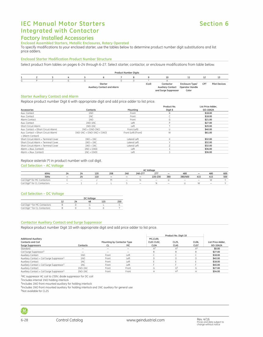
www.geindustrial.com Rev. 4/16Prices and data subject tochange without notice
Control Catalog6-28
IEC Manual Motor StartersIntegrated with Contactor
Section 6
Factory Installed AccessoriesEnclosed Assembled Starters, Metallic Enclosures, Rotary OperatedTo specify modifications to your enclosed starter, use the tables below to determine product number digit substitutions and list price adders.
Enclosed Starter Modification Product Number StructureSelect product from tables on pages 6-24 through 6-27. Select starter, contactor, or enclosure modifications from table below.
Product Number Digits
1 2 3 4 5 6 7 8 9 10 11 12 13G P 2 6 G 0 0 * A
Starter (Coil) Contactor Enclosure Type/ CPT Pilot DevicesAuxiliary Contact and Alarm Auxiliary Contact Operator Handle
and Surge Suppressor Color
Starter Auxiliary Contact and AlarmReplace product number Digit 6 with appropriate digit and add price adder to list price.
Product No. List Price Adder, Accessories Contacts Mounting Digit 6 GO-10A2AAux. Contact 1NO Front B $18.00Aux. Contact 1NC Front C $18.00Alarm Contact 1NO Front G $21.00Aux. Contact 1NO-1NC Left P $27.00Short Circuit Alarm 1NO-1NC Left T $20.00Aux. Contact + (Short Circuit Alarm) 1NO + (1NO-1NC) Front (Left) U $40.00Aux. Contact + (Short Circuit Alarm) 1NO-1NC + (1NO-1NC) + [1NO] Front (Left) [Front] W $61.00+ [Alarm Contact]Short Circuit Alarm + Terminal Cover 1NO + 1NC Lateral Left X $32.00Short Circuit Alarm + Terminal Cover 1NO + 1NC Lateral Left Y $32.00Short Circuit Alarm + Terminal Cover 1NO + 1NC Lateral Left Z $32.00Alarm + (Aux. Contact) 1NO + (1NO) Left 1 $36.00Alarm + (Aux. Contact) 1NC + (1NO) Left 3 $36.00
Replace asterisk (*) in product number with coil digit.Coil Selection – AC Voltage
AC Voltage60Hz 24 24 120 208 240 240-277 277 — 480 — 480 60050Hz — 24 110 — — — 220-230 380 380/400 415 415 500
Coil Digit* for MC Contactors C — J M — N — U — — W YCoil Digit* for CL Contactors — 1 J L S — N — U W — Y
Coil Selection – DC VoltageDC Voltage
12 24 48 125 250Coil Digit * for MC Contactors B D G L SCoil Digit * for CL Contactors B D G K T
Contactor Auxiliary Contact and Surge SuppressorReplace product number Digit 10 with appropriate digit and add price adder to list price.
Product No. Digit 10Product No. Digit 10
Additional Auxiliary MC,CL00, Contacts and Coil Mounting by Contactor Type CL01 CL02, CL25, CL06, List Price Adder,Surge Suppressors Contacts CL MC CL04 CL45 CL07 GO-10A2AStandard — — — A2 A3 A4 $0.00Coil Surge Suppressor1 — — — B B B $27.00Auxiliary Contact 1NO Front Left C C C $18.00Auxiliary Contact + Coil Surge Suppressor1 1NO Front Left D D D $45.00Auxiliary Contact 1NC Front Left E E E $18.00Auxiliary Contact + Coil Surge Suppressor1 1NC Front Left F F F $45.00Auxiliary Contact 1NO-1NC Front Front G G5 G $27.00Auxiliary Contact + Coil Surge Suppressor1 1NO-1NC Front Front H H5 H $54.00
1RC suppressor AC coil to 230V; diode suppressor for DC coil2Includes internal 1NO holding interlock3Includes 1NO front mounted auxiliary for holding interlock4Includes 1NO front mounted auxiliary for holding interlock and 1NC auxiliary for general use5Not available for CL25

www.geindustrial.com Control Catalog 6-29
IEC Manual Motor StartersIntegrated with Contactor
Rev. 4/16Prices and data subject tochange without notice
Section 6
Control Power TransformerIncludes oversized enclosure (required for CPT).Replace product number Digits 11 and 12 with appropriate digits and add price adder to list price.
50VA 150VAVoltage Product No. Digits 11 & 12 List Price Adder, Product No. Digits 11 & 12 List Price Adder,
Primary Secondary Operator Color Type 1 Type 3R/12 GO-10A2A Type 1T Type 3R/12 GO-10A2A480/240V 120V Black 5B 7B $230.00 5F 7F $275.00208V 120V Black 5C 7C $230.00 5G 7G $275.00277V 120V Black 5D 7D $230.00 5H 7H $275.00575V 120V Black 5E 7E $230.00 5J 7J $275.00480/240V 24V Black 5K 7K $230.00 5P 7P $275.00208V 24V Black 5L 7L $230.00 5Q 7Q $275.00277V 24V Black 5M 7M $230.00 5R 7R $275.00575V 24V Black 5N 7N $230.00 5S 7S $275.00
For red/yellow operator, replace 5 with 6, or 7 with 8 in Digit 11 above.
Pilot DevicesReplace product number Digit 13 with appropriate digit and add price adder to list price.
Product No. List Price Adder, Pilot Device Digit 13 GO-10A2ASTART/STOP Push Button B $144.00START/STOP Mushroom Head Push Button C $144.00START/STOP Push Button with Red/Green ON Pilot Light1 D $288.00START/STOP Push Button with Red/Green OFF Pilot Light thru Aux.1 E $315.00ON/OFF Selector Switch F $72.00ON/OFF Selector Switch with Red/Green ON Pilot Light1 G $216.00ON/OFF Selector Switch with Red/Green OFF Pilot Light thru Aux.1 H $243.00H-O-A Selector Switch J $72.00H-O-A Selector Switch with Red/Green ON Pilot Light1 K $216.00H-O-A Selector Switch with Red/Green OFF Pilot Light thru Aux.1 L $243.00Red/Green OFF Pilot Light thru Aux.1 M $171.00H-O-A Selector Switch with START Push Button N $144.00
1Pilot lights comes with both red and green lenses for field installation.
Factory Installed AccessoriesEnclosed Assembled Starters, Metallic Enclosures, Rotary Operated
Red/Yellow Rotary OperatorReplace Digit 11 in product number with digit corresponding to enclosure type.
Oversize enclosure is required for CPT and reversing control or optional if more space is desired. Replace product number Digit 11 withappropriate digit and add price adder to list price. If selecting CPT (below), oversize enclosure is included and this modification is notrequired. See CPT table.
Standard Enclosure Oversize EnclosureList Price Adder, Black Operator – Yellow/Red Operator – List Price Adder,
Enclosure Type Product No. Digit 11 GO-10A2A Product No. Digit 11 Product No. Digit 11 GO-10A2AType 1 2 $0.00 5 6 $70.00Type 3R/12 4 $0.00 7 8 $70.00

www.geindustrial.com Rev. 4/16Prices and data subject tochange without notice
Control Catalog6-30
IEC Manual Motor StartersOutline Drawings
Section 6
Outlines and Dimensions mm (in.) For Estimating Only
Manual Motor Starter - GPS1BS_ (toggle) Manual Motor Starter - GPS2BH_ (rotary)
Manual Motor Starter - GPS1BH_ (rotary)

www.geindustrial.com Control Catalog 6-31
IEC Manual Motor StartersOutline Drawings
Rev. 4/16Prices and data subject tochange without notice
Section 6
Outlines and Dimensions mm (in.) For Estimating Only
GPAC_ _FBA Auxiliary Contact Blocks - Frontal GPAC_ _LLA Auxiliary Contact Blocks - Lateral Left
GPAL_ _ _FRA Alarm Contact Blocks - Frontal
GPASLR_ _ _/GPAULR_ _ _Shunt and Undervoltage - Trip Devices
GPAD_ _ _ _LLA Alarm Contact Blocks - Lateral
GPAE11LLA Short Circuit Contact Block

www.geindustrial.com Rev. 4/16Prices and data subject tochange without notice
Control Catalog6-32
IEC Manual Motor StartersOutline Drawings
Section 6
Outlines and Dimensions mm (in.) For Estimating Only
GPS1BS_ (toggle) + Auxiliaries
GPS1BS_ (toggle) + Undervoltage Trip Device w/2NO Contacts
GPS2* + Auxiliaries
GPS1BH_ (rotary) + Auxiliaries

www.geindustrial.com Control Catalog 6-33
IEC Manual Motor StartersOutline Drawings
Rev. 4/16Prices and data subject tochange without notice
Section 6
Outlines and Dimensions mm (in.) For Estimating Only
Assembled Starter - GPS1_ (toggle) + Minicontactor MC
MC...A MC...C
Assembled Starter - GPS1BS_ (toggle) + Contactor CL00-CL01-CL02
CL00A-CL01A-CL02A CL00D-CL01D-CL02D
Assembled Starter - GPS1BS_ (toggle) + Contactor CL25
8.3(.33) 45 (1.77)
14.2 (.55)
78 (3.07)50.5 (1.98)
7.5 (.29)
92.7 (3.64)64.6 (2.54)
187.
3 (7.
37)
44.
9(1
.76)
4(
.15)
28.7 (1.13)
81.9 (3.22)46 (1.81)
76.7 (3.01)
120.4 (4
.74)
125 (4
.92)
38
.6 (1
.51)
117.4 (4.62)135.1 (5.31)
CL25A CL25D

www.geindustrial.com Rev. 4/16Prices and data subject tochange without notice
Control Catalog6-34
IEC Manual Motor StartersOutline Drawings
Section 6
Outlines and Dimensions mm (in.) For Estimating Only
Assembled Starter GPS2* + Contactor CL45
CL45A CL45D
Assembled Starter GPS2* + Contactor CL03-CL04
CL03A-CL04A CL03D-CL04D

CL06A-CL07A-CL08A
www.geindustrial.com Control Catalog 6-35
IEC Manual Motor StartersOutline Drawings
Rev. 4/16Prices and data subject tochange without notice
Section 6
Outlines and Dimensions mm (in.) For Estimating Only
Assembled Starter GPS2* + Contactor CL06-CL08
External Handle Operator

www.geindustrial.com Rev. 4/16Prices and data subject tochange without notice
Control Catalog6-36
IEC Manual Motor StartersOutline Drawings
Section 6
Outlines and Dimensions mm (in.) For Estimating Only
Non-metal Enclosure for GPS1BSAA-GPS1BSAP Surface Mounting
Non-metal Enclosure for GPS1BSAA-GPS1BSAP Surface Mounting with Padlocking Device

www.geindustrial.com Control Catalog 6-37
IEC Manual Motor StartersOutline Drawings
Rev. 4/16Prices and data subject tochange without notice
Section 6
Outlines and Dimensions mm (in.) For Estimating Only
Non-metal Enclosure for GPS1BSAA-GPS1BSAP Surface Mounting with Emergency Push Button
Non-metal Enclosure for GPS1BSAA-GPS1BSAP Flush Mounting

www.geindustrial.com Rev. 4/16Prices and data subject tochange without notice
Control Catalog6-38
IEC Manual Motor StartersOutline Drawings
Section 6
Outlines and Dimensions mm (in.) For Estimating Only
Non-metal Enclosure for GPS1BSAA-GPS1BSAP Flush Mounting with Padlocking Device
Metal Enclosure for GPS1BH_ Starter, NEMA Type 1 (Drawing 55-216916)

www.geindustrial.com Control Catalog 6-39
IEC Manual Motor StartersOutline Drawings
Rev. 4/16Prices and data subject tochange without notice
Section 6
Outlines and Dimensions mm (in.) For Estimating Only
Metal Enclosure for GPS2BH_ Starter, NEMA Type 1 (Drawing 55-216917)
Metal Enclosure for GPS1BH_/GPS2BH_ Starter, NEMA Type 3R/12 (Drawing 55-216918)
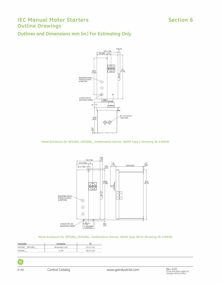
www.geindustrial.com Rev. 4/16Prices and data subject tochange without notice
Control Catalog6-40
IEC Manual Motor StartersOutline Drawings
Section 6
Outlines and Dimensions mm (in.) For Estimating Only
Controller Contactor “A”
GPS1BH__/GPS2BH__ All except CL04 33.5 (1.32)
GPS1BH__ CL04 38.4 (1.51)
Metal Enclosure for GPS1BH_/GPS2BH_ Combination Starter, NEMA Type 1 (Drawing 55-216919)
Metal Enclosure for GPS1BH_/GPS2BH_ Combination Starter, NEMA Type 3R/12 (Drawing 55-216920)

www.geindustrial.com Control Catalog 6-41
IEC Manual Motor StartersOutline Drawings
Rev. 4/16Prices and data subject tochange without notice
Section 6
Outlines and Dimensions mm (in.) For Estimating Only
Metal Enclosure for GPS1BH_/GPS2BH_ Reversing Combination Starter orCombination Starter with CPT, NEMA Type 1 (Drawing 55-216921)
Metal Enclosure for GPS1BH_/GPS2BH_ Reversing Combination Starter or Combination Starter with CPT, NEMA Type 3R/12 (Drawing 55-216922)

www.geindustrial.com Rev. 4/16Prices and data subject tochange without notice
Control Catalog6-42
IEC Manual Motor StartersWiring Diagrams – Accessories
Section 6
GPAC_ _FBA Front Mount Auxiliary Contact GPAC_ _LRA Side Mount Alarm/Auxiliary Contact
GPAC_ _FRA Front Mount Alarm Contact
GPAC_ _LLA Side Mount Auxiliary Contact
GPAE11LLA Side Mount Short Circuit Alarm
GPASLRA_ _Side Mount Shunt Trip

www.geindustrial.com Control Catalog 6-43
IEC Manual Motor StartersWiring Diagrams – Accessories
Rev. 4/16Prices and data subject tochange without notice
Section 6
GPAULRAA_Side Mount Undervoltage Release GPAU20L_AA_Side Mount Undervoltage Release with 2 NO early make contacts
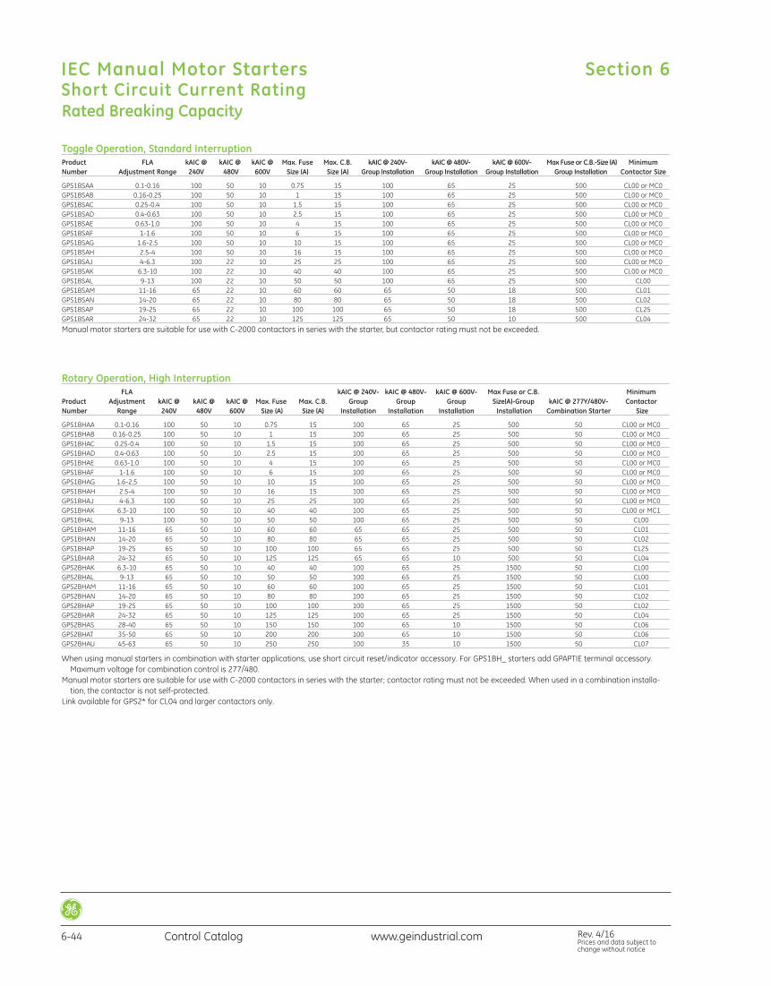
www.geindustrial.com Rev. 4/16Prices and data subject tochange without notice
Control Catalog6-44
IEC Manual Motor StartersShort Circuit Current Rating
Section 6
Rated Breaking Capacity
Toggle Operation, Standard InterruptionProduct FLA kAIC @ kAIC @ kAIC @ Max. Fuse Max. C.B. kAIC @ 240V- kAIC @ 480V- kAIC @ 600V- Max Fuse or C.B.-Size (A) MinimumNumber Adjustment Range 240V 480V 600V Size (A) Size (A) Group Installation Group Installation Group Installation Group Installation Contactor Size
GPS1BSAA 0.1-0.16 100 50 10 0.75 15 100 65 25 500 CL00 or MC0GPS1BSAB 0.16-0.25 100 50 10 1 15 100 65 25 500 CL00 or MC0GPS1BSAC 0.25-0.4 100 50 10 1.5 15 100 65 25 500 CL00 or MC0GPS1BSAD 0.4-0.63 100 50 10 2.5 15 100 65 25 500 CL00 or MC0GPS1BSAE 0.63-1.0 100 50 10 4 15 100 65 25 500 CL00 or MC0GPS1BSAF 1-1.6 100 50 10 6 15 100 65 25 500 CL00 or MC0GPS1BSAG 1.6-2.5 100 50 10 10 15 100 65 25 500 CL00 or MC0GPS1BSAH 2.5-4 100 50 10 16 15 100 65 25 500 CL00 or MC0GPS1BSAJ 4-6.3 100 22 10 25 25 100 65 25 500 CL00 or MC0GPS1BSAK 6.3-10 100 22 10 40 40 100 65 25 500 CL00 or MC0GPS1BSAL 9-13 100 22 10 50 50 100 65 25 500 CL00GPS1BSAM 11-16 65 22 10 60 60 65 50 18 500 CL01GPS1BSAN 14-20 65 22 10 80 80 65 50 18 500 CL02GPS1BSAP 19-25 65 22 10 100 100 65 50 18 500 CL25GPS1BSAR 24-32 65 22 10 125 125 65 50 10 500 CL04
Manual motor starters are suitable for use with C-2000 contactors in series with the starter, but contactor rating must not be exceeded.
Rotary Operation, High InterruptionFLA kAIC @ 240V- kAIC @ 480V- kAIC @ 600V- Max Fuse or C.B. Minimum
Product Adjustment kAIC @ kAIC @ kAIC @ Max. Fuse Max. C.B. Group Group Group Size(A)-Group kAIC @ 277Y/480V- ContactorNumber Range 240V 480V 600V Size (A) Size (A) Installation Installation Installation Installation Combination Starter Size
GPS1BHAA 0.1-0.16 100 50 10 0.75 15 100 65 25 500 50 CL00 or MC0GPS1BHAB 0.16-0.25 100 50 10 1 15 100 65 25 500 50 CL00 or MC0GPS1BHAC 0.25-0.4 100 50 10 1.5 15 100 65 25 500 50 CL00 or MC0GPS1BHAD 0.4-0.63 100 50 10 2.5 15 100 65 25 500 50 CL00 or MC0GPS1BHAE 0.63-1.0 100 50 10 4 15 100 65 25 500 50 CL00 or MC0GPS1BHAF 1-1.6 100 50 10 6 15 100 65 25 500 50 CL00 or MC0GPS1BHAG 1.6-2.5 100 50 10 10 15 100 65 25 500 50 CL00 or MC0GPS1BHAH 2.5-4 100 50 10 16 15 100 65 25 500 50 CL00 or MC0GPS1BHAJ 4-6.3 100 50 10 25 25 100 65 25 500 50 CL00 or MC0GPS1BHAK 6.3-10 100 50 10 40 40 100 65 25 500 50 CL00 or MC1GPS1BHAL 9-13 100 50 10 50 50 100 65 25 500 50 CL00GPS1BHAM 11-16 65 50 10 60 60 65 65 25 500 50 CL01GPS1BHAN 14-20 65 50 10 80 80 65 65 25 500 50 CL02GPS1BHAP 19-25 65 50 10 100 100 65 65 25 500 50 CL25GPS1BHAR 24-32 65 50 10 125 125 65 65 10 500 50 CL04GPS2BHAK 6.3-10 65 50 10 40 40 100 65 25 1500 50 CL00GPS2BHAL 9-13 65 50 10 50 50 100 65 25 1500 50 CL00GPS2BHAM 11-16 65 50 10 60 60 100 65 25 1500 50 CL01GPS2BHAN 14-20 65 50 10 80 80 100 65 25 1500 50 CL02GPS2BHAP 19-25 65 50 10 100 100 100 65 25 1500 50 CL02GPS2BHAR 24-32 65 50 10 125 125 100 65 25 1500 50 CL04GPS2BHAS 28-40 65 50 10 150 150 100 65 10 1500 50 CL06GPS2BHAT 35-50 65 50 10 200 200 100 65 10 1500 50 CL06GPS2BHAU 45-63 65 50 10 250 250 100 35 10 1500 50 CL07
When using manual starters in combination with starter applications, use short circuit reset/indicator accessory. For GPS1BH_ starters add GPAPTIE terminal accessory.Maximum voltage for combination control is 277/480.
Manual motor starters are suitable for use with C-2000 contactors in series with the starter; contactor rating must not be exceeded. When used in a combination installa-tion, the contactor is not self-protected.
Link available for GPS2* for CL04 and larger contactors only.

Rev. 4/16Prices and data subject tochange without notice
www.geindustrial.com Control Catalog 6-45
IEC Manual Motor StartersType 2 Short Circuit Rating
Section 6
Type 2 CoordinationUnder short circuit conditions, the starter must not result in dan-ger to persons or the installation. After short circuit, the startershall be capable of further use. No damage to the overload relayor other parts shall occur, except that welding of the contactorcontacts is permitted when they are easily separated (as by ascrewdriver) without significant deformation. Minimum front electrical clearance is 1” with CL06 and CL07 contactors, 0.8”with all other contactors.
100kA@240V UL508E Investigation (Individual Group or Combination)*
FLA Minimum Contactor Size Starter Adjustment Product @ 100kA @ 240V Link @ 100kA @ 240VType Range Number Interrupt Level Interrupt Level
GPS1 0.1-0.16 GPS1BHAA CL00 GPF1L02*GPS1 0.16-0.25 GPS1BHAB CL00 GPF1L02*GPS1 0.25-0.4 GPS1BHAC CL00 GPF1L02*GPS1 0.4-0.63 GPS1BHAD CL00 GPF1L02*GPS1 0.63-1.0 GPS1BHAE CL00 GPF1L02*GPS1 1-1.6 GPS1BHAF CL00 GPF1L02*GPS1 1.6-2.5 GPS1BHAG CL00 GPF1L02*GPS1 2.5-4 GPS1BHAH CL00 GPF1L02*GPS1 4-6.3 GPS1BHAJ CL00 GPF1L02*GPS1 6.3-10 GPS1BHAK CL00 GPF1L02*GPS1 9-13 GPS1BHAL CL01 GPF1L02*GPS1 11-16 GPS1BHAM CL02 GPF1L02*GPS1 14-20 GPS1BHAN CL04 GPF1L04*GPS1 19-25 GPS1BHAP CL04 GPF1L04*GPS1 24-32 GPS1BHAR CL04 GPF1L04*GPS2 6.3-10 GPS2BHAK CL04 GPF2L04*GPS2 9-13 GPS2BHAL CL04 GPF2L04*GPS2 11-16 GPS2BHAM CL04 GPF2L04*GPS2 14-20 GPS2BHAN CL04 GPF2L04*GPS2 19-25 GPS2BHAP CL04 GPF2L04*GPS2 24-32 GPS2BHAR CL45 GPF2L45*GPS2 28-40 GPS2BHAS CL06 GPF2L07*GPS2 35-50 GPS2BHAT CL06 GPF2L07*GPS2 45-63 GPS2BHAU CL07 GPF2L07*
50kA@380/400V per IEC947 (Individual Group or Combination)*
FLA Minimum Contactor Size Link @ 50kAStarter Adjustment Product @ 50kA @ 380/400V @ 380/400V Type Range Number Interrupt Level Interrupt Level
GPS1 0.1-0.16 GPS1BHAA CL00 GPF1L02*GPS1 0.16-0.25 GPS1BHAB CL00 GPF1L02*GPS1 0.25-0.4 GPS1BHAC CL00 GPF1L02*GPS1 0.4-0.63 GPS1BHAD LC00 GPF1L02*GPS1 0.63-1.0 GPS1BHAE CL00 GPF1L02*GPS1 1-1.6 GPS1BHAF CL00 GPF1L02*GPS1 1.6-2.5 GPS1BHAG CL01 GPF1L04*GPS1 2.5-4 GPS1BHAH CL01 GPF1L04*GPS1 4-6.3 GPS1BHAJ CL02 GPF1L04*GPS1 6.3-10 GPS1BHAK CL25 GPF1L25*GPS1 9-13 GPS1BHAL CL25 GPF1L25*GPS1 11-16 GPS1BHAM CL25 GPF1L25*GPS1 14-20 GPS1BHAN CL25 GPF1L25*GPS1 19-25 GPS1BHAP CLL25 GPF1L25*GPS1 24-32 GPS1BHAR CL25 GPF1L25*GPS2 6.3-10 GPS2BHAK CL04 GPF2L04*GPS2 9-13 GPS2BHAL CL04 GPF2L04*GPS2 11-16 GPS2BHAM CL04 GPF2L04*GPS2 14-20 GPS2BHAN CL04 GPF2L04*GPS2 19-25 GPS2BHAP CL04 GPF2L04*GPS2 24-32 GPS2BHAR CL04 GPF2L04*GPS2 28-40 GPS2BHAS CL45 GPF2L45*GPS2 35-50 GPS2BHAT CL06 GPF2L07*GPS2 45-63 GPS2BHAU CL07 GPF2L07*
50kA@480V UL508E Investigation (Individual Group or Combination)*
FLA Minimum Contactor Size Starter Adjustment Product @ 50kA @ 480V Link @ 50kA @ 480VType Range Number Interrupt Level Interrupt Level
GPS1 0.1-0.16 GPS1BHAA CL01 GPF1L02*GPS1 0.16-0.25 GPS1BHAB CL01 GPF1L02*GPS1 0.25-0.4 GPS1BHAC CL01 GPF1L02*GPS1 0.4-0.63 GPS1BHAD CL01 GPF1L02*GPS1 0.63-1.0 GPS1BHAE CL01 GPF1L02*GPS1 1-1.6 GPS1BHAF CL01 GPF1L02*GPS1 1.6-2.5 GPS1BHAG CL25 GPF1L25*GPS1 2.5-4 GPS1BHAH CL25 GPF1L25*GPS1 4-6.3 GPS1BHAJ CL25 GPF1L25*GPS1 6.3-10 GPS1BHAK CL25 GPF1L25*GPS1 9-13 GPS1BHAL CL25 GPF1L25*GPS1 11-16 GPS1BHAM CL25 GPF1L25*GPS1 14-20 GPS1BHAN CL25 GPF1L25*GPS1 19-25 GPS1BHAP CL04 GPF1L04*GPS1 24-32 GPS1BHAR CL04 (35kA) GPF1L04*GPS2 6.3-10 GPS2BHAK CL04 GPF2L04*GPS2 9-13 GPS2BHAL CL04 GPF2L04*GPS2 11-16 GPS2BHAM CL04 GPF2L04*GPS2 14-20 GPS2BHAN CL04 GPF2L04*GPS2 19-25 GPS2BHAP CL04 GPF2L04*GPS2 24-32 GPS2BHAR CL45 GPF2L45*GPS2 28-40 GPS2BHAS CL06 GPF2L07*GPS2 35-50 GPS2BHAT CL06 GPF2L07*GPS2 45-63 GPS2BHAU CL07 GPF2L07*
25kA (or as noted) @600V UL508E Investigation (Individual Group or Combination)*
FLA Minimum Contactor Size Starter Adjustment Product @ 25kA @ 600V Link @ 25kA @ 600VType Range Number Interrupt Level Interrupt Level
GPS1 0.1-0.16 GPS1BHAA CL00 GPF1L02*GPS1 0.16-0.25 GPS1BHAB CL00 GPF1L02*GPS1 0.25-0.4 GPS1BHAC CL00 GPF1L02*GPS1 0.4-0.63 GPS1BHAD CL00 GPF1L02*GPS1 0.63-1.0 GPS1BHAE CL00 GPF1L02*GPS1 1-1.6 GPS1BHAF CL00 GPF1L02*GPS1 1.6-2.5 GPS1BHAG CL04 GPF1L04*GPS1 2.5-4 GPS1BHAH CL04 GPF1L04*GPS1 4-6.3 GPS1BHAJ CL04 GPF1L04*GPS1 6.3-10 GPS1BHAK CL04 GPF1L04*GPS1 9-13 GPS1BHAL CL04 GPF1L04*GPS1 11-16 GPS1BHAM CL04 GPF1L04*GPS1 14-20 GPS1BHAN CL04 GPF1L04*GPS1 19-25 GPS1BHAP CL04 GPF1L04*GPS1 24-32 GPS1BHAR CL04 GPF1L04*GPS2 6.3-10 GPS2BHAK CL45 (5kA) GPF2L45*GPS2 9-13 GPS2BHAL CL45 (5kA) GPF2L45*GPS2 11-16 GPS2BHAM CL45 (5kA) GPF2L45*GPS2 14-20 GPS2BHAN CL45 (5kA) GPF2L45*GPS2 19-25 GPS2BHAP CL45 (5kA) GPF2L45*GPS2 24-32 GPS2BHAR CL45 (5kA) GPF2L45*GPS2 28-40 GPS2BHAS CL06 (10kA) GPF2L07*GPS2 35-50 GPS2BHAT CL06 (10kA) GPF2L07*GPS2 45-63 GPS2BHAU CL07 (10kA) GPF2L07*
*Maximum voltage for combination control 277/480. Minimum front electrical clearance is 1” with CL06 and CL07 contactors, and 0.8” with all other contactors.
Individual Group and Combination Starters

www.geindustrial.com Rev. 4/16Prices and data subject tochange without notice
Control Catalog6-46
IEC Manual Motor StartersSpecifications
Section 6
StartersGPS1 GPS2
Protection Thermal and Magnetic Thermal and MagneticMaximum Rated Current Imax 32A 63AMaximum Rated Operational Current Ie 32A 63AMaximum Rated HP @ 460V 20 Hp 40 hpMaximum Rated kW @ 400V 15 kW 30kWPower Loss 0.16-25A: 7 W 32A: 8.5 W 6.3-32A: 11W 40-50A:
15W 63A: 17WWidth 45 mm 55 mmHeight 90 mm 120 mmDepth 75 mm (GPS1BS*)/ 107.5 mm
92.5 mm (GPS1BH*)No. of Poles 3 3Operation Toggle (GPS1BS*)/ Rotary
Rotary (GPS1BH*)Mounting Position Turning to Front 30° 30°Mounting Position Turning to Back 90° 90°Mounting Position Turning to Side 180° 180°DIN Rail Mounting Yes YesMounting Screws 2 M4 (#6 screws) with Yes
Optional Mounting TabOperation Altitude Up to 2000 Meters Up to 2000m (6500 ft)
(6500 Feet)Storage Temperature –40 to +80° C (–40 to 176° F) –40 to +80° C
(–40 to 176° F)Operation Temperature –20 to +60° C (–4 to 140° F) –20 to +60° C
(–4 to 140° F)Temperature Compensation –20 to +60° C (–4 to 140° F) –20 to +60° C
(–4 to 140° F)Rated Insulation Voltage Ui 690V 690VRated Operation Voltage Ue 690V 690VRated Voltage UL, cUL 600V 600VRated Frequency 50/60 50/60Rated Impulse Withstand Strength Uimp 8KV 8KVUtilization Category IEC 60947-4-1 AC3 AC3Overload Trip Class IEC 60947-4-1 10 10Number of Current Ranges 15 9Magnetic Release Ie Max Setting 13X 13XShock Resistance to IEC60068-2-25 30 g (width 20 ms) 30 g (width 20 ms)Vibration Resist., 50-150 Hz (X,Y,Z axis) 5G Contact factoryStd DIN Rail MtgVib. Res., 50-150 Hz (X,Y,Z axis) 8G Contact factoryDIN Rail Vib. ClampsProtection Degree (per IEC529) IP20 Safe from Finger Touch IP20 Safe
from Finger TouchMechanical Performance 100,000 ops (70,000 for 32 Amp) 50,000 opsElectrical Performance 100,000 ops (70,000 for 32 Amp) 25,000 opsMax. Operation per Hour 25 25(Motor Start Up)Phase Failure Protection Yes YesTrip Test Function Yes YesTrip Indication Yes YesTerminal Type Pozidrive 2/Slotted Comb. Pozidrive 2/Slotted Comb.Max. Size Wire
1 Conductor w/o End Sleeve, solid or stranded 1-10 mm2/18-8 AWG 1-25 mm2/18-2 AWG stranded2 Conductor w/o End Sleeve, solid or stranded 1-6 mm2/18-10 AWG 1-25 mm2/18-4 AWG stranded1 Conductor w/ End Sleeve, stranded 1-6 mm2 stranded 1-16 mm2
2 Conductor w/ End Sleeve, stranded 1-6 mm2 stranded 1-16 mm2
Torque 2.0 Nm/18 lb. in. 4.0 Nm/36 lb. in.Standards
IEC 60947-1, 60947-2, 60947-4 Yes YesDin VDE66OT 100/101/102 Yes YesUL 508/CSA 22.2 Yes Yes
MarkingCE Yes Yes
ApprovalsUL, cUL listed Yes Yes
Shipping Approvals On Request On RequestPTB Test On Request On Request
Frontal Auxiliary BlocksUL Contact Rating per NEMA ICS3-125 B300, Q300Continuous Ampere Rating 5Rated Operation AC Voltage Ue 115V, 230VRated Operational AC Current Ie 1.5AAC Utilization Category AC15Rated Operation DC Voltage Ue 48V, 110V, 220VRated Operational DC Current Ie 1.38A, 0.55A, 0.27ADC Utilization Category DC13Terminal Type Pozidrive2/Slotted Comb.Max. Size Wire (75°C Cu wire only) 2 conductor 0.5-2.5 mm2/18-14 AWGTorque 0.8Nm/7 lb. in.
Frontal Mount with 1NO or 1NC Contact; Frontal Mount Alarm with 1NO or 1NC Contact.
Lateral Auxiliary BlocksUL Contact Rating per NEMA ICS3-125 A600, P300Rated Operation AC Voltage Ue 125V, 230V, 400V, 500V, 690VRated Operational AC Current Ie 4A, 4A, 2.2A, 0.5A, 0.6AAC Utilization Category AC15Rated Operation DC Voltage Ue 48V, 110V, 220VRated Operational DC Current Ie 5A, 1.3A, 0.5ADC Utilization Category DC13Terminal Type Pozidrive2/Slotted Comb.Max. Size Wire (75°C Cu wire only) 2 conductor 0.5-2.5 mm2/18-14 AWGTorque 0.8Nm/7 lb. in.Width Adds 9 mm
Lateral Mount Auxiliary with 2NO, 1NO+1NC or 2NC contacts; Lateral MountAlarm/Auxiliary with 1NO+1NO, 1NO+1NC, 1NC+1NO, 1NC+1NC; Short CircuitSignal Contact 1NO+1NC (SPDT)
Shunt TripPower Consumption Pick-up (va/watts) 21/12Power Consumption Tripping Voltage 0.7-1.1 VeMax. Operation Supply 5 ms for DC coil Power Consumption Pick-Up Voltage 0.85 - 1.1 VeMax. Size Wire (75°C Cu wire only) 2 conductor 0.5-2.5 mm2/18-14 AWGTorque 0.8Nm/7 lb. in.Width Adds 18 mm
Undervoltage ReleasePower Consumption Pick-up (va/watts) 21/12Power Consumption Holding (va/watts) 8/1.2Power Consumption Tripping Voltage 0.35-0.7 VePower Consumption Pick-Up Voltage 0.85-1.1 VeTorque 0.8Nm/7 lb. in.Max. Size Wire (75°C Cu wire only) 2 conductor 0.5-2.5 mm2/18-14 AWGWidth Adds 18 mm

www.geindustrial.com Control Catalog 6-47
IEC Manual Motor StartersTime Current Curves
Rev. 4/16Prices and data subject tochange without notice
Section 6
GPS1
The thermal release trip current curve applies to cold state. For single phase and DC loads the three phase must be connected inseries. The magnetic release is based on the rated current In, which is the maximum value of the setting range of the manual motorstarter. If the current is set to a lower value, the tripping current is increased by a corresponding factor. The short circuit release is setat the factory to a value equivalent to 13 times the rated current of the manual motor starter.

www.geindustrial.com Rev. 4/16Prices and data subject tochange without notice
Control Catalog6-48
IEC Manual Motor StartersTime Current Curves
Section 6
GPS2
The thermal release trip current curve applies to cold state. For single phase and DC loads the three phase must be connected inseries. The magnetic release is based on the rated current In, which is the maximum value of the setting range of the manual motorstarter. If the current is set to a lower value, the tripping current is increased by a corresponding factor. The short circuit release is setat the factory to a value equivalent to 13 times the rated current of the manual motor starter.