ge measurement & control · pdf filege measurement & control 1100 technology park...
TRANSCRIPT

Mounting and Wiring the Aurora Rack Mount Configuration
GE Measurement & Control
916-140, Rev A December 2013
Mounting the Aurora Rack Mount Configuration
Figure 1: Aurora Drawing for Rack Mounting (Dwg. 712-1890, rev. A)
1100 Technology Park DriveBillerica, MA 01821-4111Web: www.ge-mcs.com

Mounting and Wiring the Aurora Rack Mount Configuration December 2013
Mounting (cont.)
1. Pre-wire the output connectors in accordance with wiring drawing.
2. Use approved AC input power cord provided.
3. Sample inlet/outlet connections to be sure they are leak free.
4. For additional support use a Rack Rail Kit as shown below or equivalent.
Figure 2: Standard Rack Mount Rail Kit
5. Install 4 fasteners (12-24 or 10-32 threaded fasteners) to retain the rack mount.
2 of 7 916-140A

Mounting and Wiring the Aurora Rack Mount Configuration December 2013
Wiring the Aurora Rack Mount Configuration
Figure 3: Wiring Diagram
TB1 contains connections for the alarm relay and 4-20mA analog output ‘C’ and the Alarm relay contacts. NC is Normally closed contact, C is Common, and NO is normally open contact.
Use shielded 18 – 22 AWG (0.82-0.33 mm2) twisted pair wire for all I/O connections.
TB2 contains PORT1 and PORT 2 designated SCADA and Service respectively. Either port may be configured for RS232 or RS485.
To ensure compliance to EN requirements, a shielded cable is required for these connections and the shield must be terminated to the SHD terminal. Also, a ferrite cable clamp will need to be added close to the I/O connector. The ferrite cable clamp should have the characteristics shown in Table 1 below:
Table 1: Typical Cable Clamp Impedance ()
10 MHz 77
25 MHz+ 125
100 MHz+ 210
250 MHz 260
TB1 Callout
TB2 Callout
3 of 7 916-140A

Mounting and Wiring the Aurora Rack Mount Configuration December 2013
Wiring the Aurora Rack Mount Configuration (cont.)
A typical cable clamp is shown in Figure 4 below:
Figure 4: Cable Clamp
For operation on RS-485, 2-wire, half-duplex bus, attach the RS485(+) to (+) and the RS485(-) to (-). If available, make a third connection to the RS-485 network common to RTN. Connect shield wire from the cable to SHD terminal.
For operation on RS-232, connect RS232 (TXD) to (+), RS232(RXD) to (-), and RS-232 (GND) to RTN. Connect cable shield wire to SHD terminal.
For connection to a PC interface with Auroraview software, you may used the supplied 704-668-12 cable (RS-232) w/SUB-D-9 connector to the tinned leads. (There is also a detachable AC power cord on the back panel.) Wire the cable as follows in Table 2 below.
Note: The default configuration is as shipped:
Table 2: Wiring Table
Color CodeAurora Terminal
(Port 1 Pin) (Port 2 Pin)
White TX + (10) (14)
Red RX - (11) (15)
Green Return RTN (12) (16)
Black Shield SHD (13) (13)
Table 3: Default ConfigurationBAUD Rate: 115,200
Parity: Even
ID Note: 1 for Port 1, 2 for Port 2
4 of 7 916-140A

Mounting and Wiring the Aurora Rack Mount Configuration December 2013
Figure 5: Back Panel Labels
Figure 6: Location of Model and Serial Number
5 of 7 916-140A

Mounting and Wiring the Aurora Rack Mount Configuration December 2013
Figure 7: Power, CE and Inlet Labels
Figure 8: Back Panel Label -- Wiring Diagram
6 of 7 916-140A
Mounting and Wiring the Aurora Rack Mount Configuration December 2013
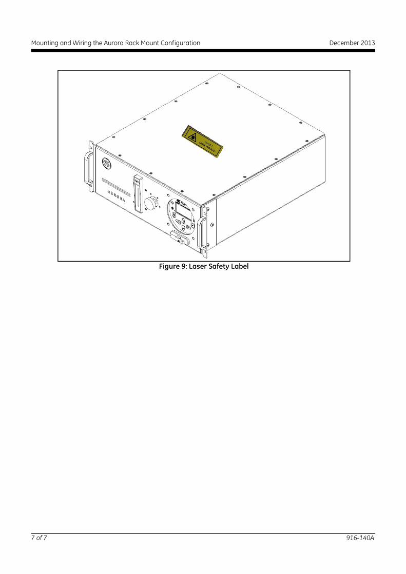
Figure 9: Laser Safety Label
7 of 7 916-140A