ge222 occurrence investigation factual data collection ... · aviation safety council taipei,...
TRANSCRIPT
Aviation Safety Council
Taipei, Taiwan
GE222 Occurrence Investigation
Factual Data Collection
Group Report
Aircraft Systems Group
December 26, 2014
ASC-FRP-14-12-03

Intentionally Left Blank

Contents
I. Team Organization ................................................................................................. 1
II. History of Major Activities ..................................................................................... 3
III. Factual Description ................................................................................................. 4
1.3 Damage to aircraft .................................................................................................... 4
1.6 Aircraft information ................................................................................................. 4
1.6.1 General information ................................................................................... 4
1.6.1.1 Aircraft and engine basic information ................................................. 4
1.6.2 Aircraft maintenance records ..................................................................... 6
1.6.3 Enhanced Ground Proximity Warning System .......................................... 6
1.12 Wreckage and impact information ....................................................................... 9
1.12.1 Wreckage survey ...................................................................................... 9
1.12.1.1 General .............................................................................................. 9
1.12.1.2 Parts found among the bushes ......................................................... 11
1.12.1.3 Wreckage located around houses area ............................................ 12
1.12.1.4 Power plant ...................................................................................... 26
1.12.1.5 Miscellaneous .................................................................................. 31
1.16 Test and research .................................................................................................. 32
1.16.1 Simulation flights of EGPWS ................................................................ 32
1.16.2 EGPWS NVM data download and simulation....................................... 33
1.16.3 Fuel/ Oil samples test ............................................................................. 34
IV. Appendices............................................................................................................ 35
V. Attachment List..................................................................................................... 35

1
I. Team Organization
Chairman:
Steven Su
Aviation Safety Council (ASC), Taiwan ROC
Members:
1 David Lee
Aviation Safety Council (ASC), Taiwan ROC
2 Yanni Lee, Ph.D.
Aviation Safety Council (ASC), Taiwan ROC
3 Julien Ballester
BEA, France
4 Antton Etchemendy
ATR, France
5 Chng Seng Piang
ATR, France
6 Marc Gratton
PWC, Canada
7 David Studtmann
Honeywell, United states
8 Peter Wang
Civil Aeronautics Administration (CAA), Taiwan ROC
9 Mike Huang
Civil Aeronautics Administration (CAA), Taiwan ROC

2
10 Nicolas Liaw
Civil Aeronautics Administration (CAA), Taiwan ROC
11 William Lin
Civil Aeronautics Administration (CAA), Taiwan ROC
12 Nicolas Hung
TransAisa Airways
13 Wilson Ling
TransAisa Airways
14 Chun-yen Lee
TransAisa Airways

3
II. History of Major Activities
Date Activities
7/23/14 Preparation for on-scene investigation
7/24/14 Site visiting, key components collection and wreckage
documentation
7/25/14 Wreckage cutting, movement and storage
7/26/14 Site visiting, wreckage and engine inspection with BEA,
ATR and PWC
7/27/14 Wreckage and engine inspection with BEA, ATR and PWC
7/28/14
1. Attended organizational meeting, gathering maintenance
records
2. cockpit mockup finished, wreckage protection from
typhoon.
3. PWC field notes accomplished
7/29/14 EGPWS and yaw damper systems functions review
7/30/14 BEA/ATR field notes accomplished
8/5/14 Reviewed TLB from date April 2, 2014 to July 23, 2013
8/6/14 Accomplished TLB review from date January 2, 2014 to July
23, 2013
8/7/14 Accomplished one year deferred defects records review
8/8/14 Fuel and oil sample/filters examination by Air force Base
10/16/14 EGPWS computer data download completed by Honeywell
10/30/14 Received EGPWS analysis from Honeywell
11/4/14
To
11/7/14
Simulation flights at ATR, Toulouse
11/5/14 Received EGPWS analysis update from Honeywell

4
III. Factual Description
Detailed description of the damages and wreckage locations on scene are
shown in Attachment 3-1 B-22810 Occurrence-Site Wreckage Field Notes,
Attachment 3-2 14-077 TNA Factual Notes and Attachment 3-3
Maintenance group report-on scene.
1.3 Damage to aircraft
The aircraft was destroyed.
1.6 Aircraft information
1.6.1 General information
1.6.1.1 Aircraft and engine basic information
Basic information of the occurrence aircraft is shown in Table 1.6-1

5
Table 1.6-1 Aircraft Basic Information Table
Aircraft basic information(statistics date: July 23, 2014)
Nationality Taiwan, R.O.C.
Aircraft registration number B-22810
Aircraft Model ATR72-212A
Manufacturer ATR
Aircraft serial number 0642
Date manufactured June 14, 2000
Delivery date July 6, 2000
Owner TransAsia Airways
Operator TransAsia Airways
Number of certificate of
registration 93-945
Certificate of airworthiness,
validity date 102-08-145, July 31, 2014
Total flight time (hours) 27039:27
Total flight cycles 40387
Last check, date 9C6E “A” CHK / May 28, 2014
Flight hours/ cycles elapsed since
last "A" check 349:18/ 522

6
Basic information about the two Pratt & Whitney Canada PW127F/M
engines is shown in Table 1.6-2
Table 1.6-2 Engine Basic Information Table
Engine basic information(statistics date: July 23, 2014)
Number/position No. 1/ Left No. 2/ Right
Serial number AV0051 EB0069
Manufacture date APR 26, 1998 MAY 06, 2001
Date of last shop visit MAR 23, 2012
/REPAIR
JAN 23, 2013
/OVERHAUL
Date of installation JUN 13, 2012 FEB 20, 2013
Time since installed
(hours) 4185:25 3076:54
Cycle since installed 6388 4670
Total time(hours) 26657:55 18712:27
Total cycles 40239 23015
1.6.2 Aircraft maintenance records
The Technical Log Book (TLB), Deferred defects records, status of
Airworthiness Directive (AD) and Service Bulletin (SB) status were
shown in Attachment 3-4, 3-5 and 3-6. There was no defects report and
Minimum Equipment List (MEL) items of the occurrence flight when the
B-22810 was dispatched from Kaohsiung Airport to Magong Airport. A
review of the last 6 months of TLB indicated a repeated defect which was
"PROBE HTG STBY PITOT LT ON". It occurred twice, on May 8, 2014
and May 9, 2014. After the second replacement of the standby pitot probe
on May 9, 2014, there was no more defect report related to this item.
Examination of the last 6 months TLB of B-22810, there is no system
anomaly related to the occurrence. A review of maintenance records
provided by TransAsia Airways reveals that B-22810 was in compliance
with all applicable Airworthiness Directive and Service Bulletin.
1.6.3 Enhanced Ground Proximity Warning System
The Enhanced Ground Proximity Warning System, EGPWS, is a Terrain

7
Awareness and Warning System (TAWS) providing basic GPWS functions
plus additional enhanced terrain alerting and display features. The EGPWS
uses aircraft inputs including geographic position, attitude, altitude,
airspeed, and glideslope deviation. These are used with respect to internal
terrain, obstacle, and airport databases to predict a potential conflict
between the aircraft flight path and terrain or an obstacle. A conflict will
result in the EGPWS providing a visual and audio caution or warning alert.
Additionally, the EGPWS provides alerts for excessive glideslope
deviation, too low with flaps or gear not in landing configuration, and
optionally provides bank angle and altitude callouts based on system
configuration selection.
The B-22810 aircraft was equipped with Honeywell Enhanced Ground
Proximity Warning System, EGPWS, model MARK VIII, Part Number:
965-1216-011. The EGPWS performs the following alert modes:
- Basic GPWS modes
Mode 1: excessive descent rate
Mode 2: excessive terrain closure rate
Mode 3: altitude loss after take-off
Mode 4: unsafe terrain clearance
Mode 5: below glideslope
Mode 6: altitude callouts
- Enhanced modes
Terrain Clearance Floor (TCF)
Terrain Awareness & Display (TAD)
The Terrain Clearance Floor (TCF) mode creates an increasing terrain
clearance envelop around the airport runway directly related to the distance
from the runway. The alert is based on current aircraft location, nearest
runway center point position and radio altitude. TCF is activated during
takeoff, cruise and final approach and complement existing Mode 4 by
providing an alert based on insufficient terrain clearance even when in
landing configuration. A Runway Field Clearance Floor (RFCF) alert is
also provided for runways that are located on top of hill. This alert is
similar to the TCF alert but is based on height about runway. The aural
message "Too Low Terrain" will occur once at the initial TCF enveloper
penetration and one time thereafter for each 20% degradation in radio
altitude. At the same time "GPWS" red alert lamp are illuminated and
remain on until the alert envelop is exited.

8
Figure 1.6-1 TCF alert curve
Figure 1.6-2 Plan view of expanded alert
The terrain awareness function uses aircraft geographic position provided

9
by an aircraft GPS or an optional internal GPS card, aircraft altitude and a
worldwide terrain database to predict potential conflicts between the
aircraft flight path and the terrain, and to provide aural alert and graphic
displays of the conflicting terrain. Caution and Warning envelops below
and ahead of the aircraft path are computed as a function of groundspeed
and flight path angle. If the terrain penetrates the Caution envelop
boundary, an aural message "TERRIN AHEAD. TERRAIN AHEAD" is
generated with the red "GPWS" lights illuminated on each instrument
panel. Simultaneously, terrain areas, which conflict with the Caution
criteria, are shown in solid yellow on the Terrain Display. If the terrain
penetrates the Warning envelope boundary, an aural message "TERRAIN
AHEAD, PULL UP" is generated with the red "GPWS" lights illuminated
on each instrument panel. Simultaneously, terrain areas, which conflict
with the warning criteria, are shown in solid red on the Terrain Display.
The terrain data can be display on the Electronic Flight Instrument System
(EFIS). When the Terrain Display is present, it replaces the Weather Radar
display and can be available to the flight crew at any time. A discrete
pop-up signal provided by EGPWS is used to automatically display on
EFIS the detected threatening terrain with an auto-range of 10Nm
whatever is the previous information displayed. The local terrain forward
of the aircraft is depicted as variable density dot patterns in green, yellow
or red. The density and color being a function of how closed the terrain is
relative to aircraft altitude. Terrain Alerts are depicted by painting the
threatening terrain as solid yellow or red.
1.12 Wreckage and impact information
1.12.1 Wreckage survey
1.12.1.1 General
The aircraft wreckage was generally distributed into two areas, the bushes
area (Zone 1) and houses area (Zone 2), referred to Figure 1.12-1.
Compared to houses area, only very limited wreckage was found around
the bushes. The parts or debris found around bushes were separated from
radome, nose gear doors, left main landing gear door and left air condition
system components. The other aircraft wreckage was distributed at houses
area. The nose landing gear, right main landing gear, tail cone, part of right
wing, right engine, vertical tail, and rear fuselage were separated from
aircraft. The remained aircraft (main wreckage) including right wing, left
wing, left engine, left main landing gear, forward fuselage and cockpit
were located near the house no.105, referred to Figure 1.12-2. Most of
main wreckage was heavily damaged by fire except the cockpit. The
cockpit was suffered seriously impact damage.

10
Figure 1.12-1 Wreckage distribution areas

11
Figure 1.12-2 Wreckage distribution around houses area
1.12.1.2 Parts found among the bushes
Several pieces were found in the bushes. Among those debris, some were
identified as part of:
- the nose landing gear (NLG) aft doors referred to Figure 1.12-4
- the radome referred to Figure 1.12-5
- the left-hand heat exchanger referred to Figure 1.12-3
- the ram air inlet referred to Figure 1.12-3
- the ram air check valve referred to Figure 1.12-3
- the left-hand main landing gear door referred to Figure 1.12-3
- belly faring inspection doors referred to Figure 1.12-3
- belly faring panels referred to Figure 1.12-3

12
Figure 1.12-3 Several pieces found
in the bushes
Figure 1.12-4 Nose landing gear aft
door
Figure 1.12-5 Radome parts
1.12.1.3 Wreckage located around houses area
Left wing
The leading edge for the left wing does not exhibit any major damage from
impact. Only the wing tip is broken. The engine no.1 was still attached to
the wing. The wing itself presents fire damage on half of its span.
LH Heat Exchang
er
Ram Air Inlet
LH MLG Door
RAM Check Valve

13
Figure 1.12-6 The left wing on site Figure 1.12-7 Recovered left
wingtip
The aileron was found broken in pieces and exhibits contact deformation at
the tip (deformation of the aileron horn).
Figure 1.12-8 Left aileron
The spoiler was found on the wing still attached. The actuator was freely
moving. The flap attachment was present but there was no actuator.

14
Figure 1.12-9 Left-hand wing and spoiler
Flaps were damaged by fire. The outboard one exhibits lots of fire damage
around its root (burnt composite strips). The inboard one was partially
located under the engine no.1, still attached to the wing part. Some flaps
debris which were not clearly identified may be part of the missing flap.
Figure 1.12-10 Left-hand inboard
flap, still attached to the wing
Figure 1.12-11 Left-hand outboard
flap
Spoiler

15
Figure 1.12-12 Unidentified flap parts
Some pieces from the left wing lower skin were recovered amongst the
debris.
Figure 1.12-13 Example of left lower skin pieces recovered
The left-hand inboard flap actuator was still attached to the left wing part.
It was extended up to 120 mm which was estimated around 28°
corresponding to actual flap position.

16
Figure 1.12-14 Left-hand inboard flap actuator
Right wing
The right wing was destroyed in several pieces during the crash sequence.
The root of the outer right wing box was still attached to the center wing
box which was attached to the left wing. The right wing parts which were
located with the main wreckage exhibits lots of fire damage. The
right-hand inboard flap attachment and actuator were still present on the
wing but the actuator was free of movement so it was not possible to
confirm its original position.
Figure 1.12-15 Root of the right wing and flap actuator and attachment
The part of the right wing which was located on the roof of the house
no.5-3 exhibits impact damages. The spoiler was still attached.

17
Figure 1.12-16 Piece of the right wing
The right-hand wingtip does not exhibit any direct impact damage.
Figure 1.12-17 Right wingtip
The aileron was broken in two parts. The tip is complete with the aileron
horn and the winglet.

18
Figure 1.12-18 Right aileron tip Figure 1.12-19 Right aileron
Almost all the flaps were recovered from the debris, in several pieces.
Figure 1.12-20 Right-hand inboard
flap
Figure 1.12-21 Right-hand outboard
flap

19
Figure 1.12-22 Right-hand outboard flap
Rear fuselage
The rear fuselage between the passenger door and the rear bulkhead was
recovered from the occurrence site. The ELT (Emergency Locator
Transmitter) was still inside this section of fuselage in its rack. It was
reported that the ELT was emitting after the occurrence.
Figure 1.12-23 Rear fuselage
section
Figure 1.12-24 Passenger door

20
Figure 1.12-25 Emergency Locator Transmitter
The tail part (vertical and horizontal tail fins) was in one piece after the
crash. For transportation purpose, the vertical stabilizer, the rudder, the
horizontal stabilizers and the elevators were separated. Additional
damages were made during handling.
The vertical stabilizer did not exhibit any particular damage. The leading
edge was undamaged during the crash sequence. The rudder damper,
located at the root of the vertical stabilizer) was extended up to 50 mm1.
Figure 1.12-26 Tail Figure 1.12-27 Rudder damper
1 It is assumed that this length was measured between the rod end bearing axis and
the damper body. Since rudder the damper rod end is adjustable, the exact
corresponding rudder position cannot be determined precisely. This rod length
indicates that actuator is close to or at its full retracted position i.e. rudder close to or
at its full Nose Right position (around 27° RH).

21
The rudder was found still intact with the vertical stabilizer. It did not
exhibit any damages.
Figure 1.12-28 Rudder
The leading edge of the left one exhibits no impact damage whereas the
right-hand one is deformed due to impact.
Figure 1.12-29 Horizontal stabilizer
and elevator
Figure 1.12-30 Right horizontal
stabilizer and elevator
Flight controls for the rudder and elevators were still present and free of
movement at the root of the vertical stabilizer in the aft avionics
compartment. The travel limitation unit (P/N 8236-3, S/N 5060) was
present and extended up to 55 mm2.
2 It is assumed that this measurement was taken between rod end bearing
axis and actuator body. Such rod length corresponds to an actuator fully
extended on its mechanical stop i.e. a TLU in “LO SPEED” position.

22
Figure 1.12-31 Flight controls for
rudder and elevator
Figure 1.12-32 Travel limitation
unit
The right-hand pitch trim actuator (P/N 8236-3, S/N 6126) was recovered
from the wreckage. It was extended up to 40 mm which was estimated
around 0.7° NOSE UP corresponding to the pitch trim setting. The
left-hand pitch trim actuator was not recovered from the wreckage but it
should have been present because the horizontal stabilizer was undamaged
at the occurrence site. It was not possible to confirm the symmetry of the
pitch trims.
Figure 1.12-33 Right-hand pitch trim actuator
The stick-pusher actuator (P/N 8300-1, S/N 837) was found in an extended

23
position. The extension was 100 mm3 long.
Figure 1.12-34 Stick pusher actuator Figure 1.12-35 Stick pusher actuator
extended
Landing gears
The left main landing gear was found in a locked down position. This was
confirmed with the side brace position. The wheels from this landing gear
were not able to rotate freely as tree debris was located in the hub.
Figure 1.12-36 Left main landing
gear
Figure 1.12-37 Left main wheel hub
with tree debris
The right main landing gear was found in a down and locked position. The
upper end of shock absorber was separated from trunnion leg. The wheels
3
It is assumed that this measurement was taken between rod end and casing. Such rod
length corresponds to an actuator fully extended and locked on its mechanical stop i.e.
stick-pusher actuator NOT activated.
Side brace

24
were able to rotate.
Figure 1.12-38 Right main landing gear
The nose landing gear was found broken in several pieces. It was not
possible to confirm its down and locked position.
Figure 1.12-39 Nose landing gear pieces
Cockpit and forward fuselage
The cargo door was located amongst the debris.
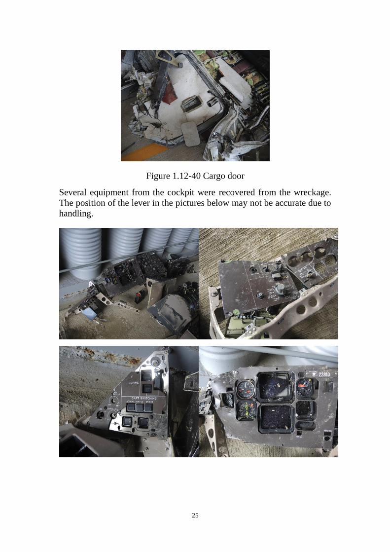
25
Figure 1.12-40 Cargo door
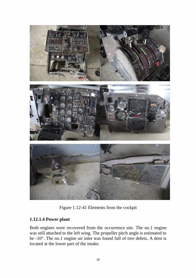
Several equipment from the cockpit were recovered from the wreckage.
The position of the lever in the pictures below may not be accurate due to
handling.
26
Figure 1.12-41 Elements from the cockpit
1.12.1.4 Power plant
Both engines were recovered from the occurrence site. The no.1 engine
was still attached to the left wing. The propeller pitch angle is estimated to
be -10°. The no.1 engine air inlet was found full of tree debris. A dent is
located at the lower part of the intake.

27
Figure 1.12-42 No.1 Engine
The no.2 engine was found separated on site. The propeller pitch angle is
estimated to be 10°. No tree debris was found in the air inlet.
Figure 1.12-43 No.2 Engine
The remaining propeller blades from the no.2 engine are shorter in size

28
than the ones on no.1 engine. The two propellers did not experience the
same environment during the crash.
No.1 ENGINE (S/N AV0051) EXAMINATION
External Condition: The engine was still fully contained in its nacelle.
The nacelle showed fire damage between the 6 and 9 o’clock position, rear
portion, just forward of the exhaust case. The remainder of the nacelle was
structurally intact. The evidence showed that this damage occurred from
external fire. The engine was partially covered in soot however there was
no evidence of fire originating from the engine itself.
External Cases: All cases were structurally intact. All oil, fuel and air
lines including the P3 line from the intercompressor case to the fuel control
were intact. All fittings leading to the fuel control were tight and secured.
Turbine Section: Examination of the 2nd stage power turbine through the
exhaust showed no evidence of damage. Oil residues covered some blades.
The turbine assembly was free to rotate and continuous with the propeller.
The power turbine blades exhibited no evidence of impact damage.
Combustion Section: The internal components were not examined.
Externally, the fuel nozzles, manifolds and all fuel delivery tubes were
intact and no evidence of fuel leakage was observed.
Compressor Section: The engine inlet was filled with a large quantity of
organic debris mostly consisting in small branches twigs and cone nuts.
This debris was carried from the time the aircraft exited the initial impact
zone with the tree line to its final post-crash resting point. The visible
portion of impeller showed light leading edge impact damage.
Reduction Gearbox: The internal components were not examined. Free
rotation was however observed and no evidence of internal distress was
noted during rotation movements.
Accessory Gearbox: The internal components were not examined
however free rotation and continuity was observed with the high pressure
rotor.
Controls and Accessories Evaluation: All components were intact and
no visual damage was observed. The fuel control unit, fuel pump,
electronic engine control, propeller controller (PEC) and propeller valve
module (PVM) were retained for precautionary examination should it be
required.
No.1 engine chip detectors and filter checks: Detailed observation

29
referred to Table 1.12.2-1.
Table 1.12.2-1 No.1 engine chip detectors and filter checks
Item Observation
Main Chip
Detector
Clean
Main Oil Filter Clean of any large debris. The residual oil
contained in the housing appeared to contain a
small quantity of fine shiny metallic like debris.
Reduction
Gearbox Scavenge
Chip Detector
Clean
Reduction
Gearbox Scavenge
Oil Filter
The filter was clean. The filter housing contained
only a small quantity of oil which could not be
drained into a sample container. The oil appeared
clear and free of debris.
Fuel Filters The low pressure filter was clean. The housing
was clean but contained no residual fuel. The
high pressure filter was not examined and
remained with the fuel pump.
No.2 ENGINE (S/N EB0069) EXAMINATION
External Condition: The engine nacelle was heavily damaged and
partially ripped off from the engine. The engine showed impact damage on
most external oil, fuel and air lines. The P3 line from the intercompressor
case to the fuel control was however intact and all fittings were tight and
secure. Fracture of the rear inlet case resulted in axial displacement of
approximately 10° towards the right side in the plane of the diffuser case.
This partially exposed the low pressure impeller shroud and gave partial
access to the impeller which could be rotated with force on a small arc.
Tactile examination of accessible impeller blades revealed light leading
impact damage. Soot and fire damage to the external airframe components
was observed behind the firewall however there was no evidence that this
fire originated from the engine itself.
External Cases: All housings of reduction gearbox appeared intact.

30
Front Inlet Case intact.: The case of rear inlet case/accessory gearbox
was fractured adjacent and into the bolting flange to the low pressure
diffuser case between the 2 and 6 o’clock position. The low pressure
diffuser case was intact except for some slight bending of its mounting
flange where the rear inlet case was found fractured. The intercompressor
case appeared structurally intact. The gas generator case appeared
structurally intact. The impact damage to the turbine support case was
visible in the plane of the power turbines. The damage was located
between the 11 and 12 and between the 2 and 3 o’clock position. This
damage prevented removal of the engine exhaust duct.
Turbine Section: The power turbine module was free to turn with no
apparent restriction. The shaft however was no longer coupled to the
reduction gearbox and propeller. Removal of the torque shaft cover on the
front inlet case revealed no damage to the torque shaft. This suggests that
the shaft is sectioned at a location corresponding to the axial displacement
of the engine. The power turbine blades exhibited no evidence of impact
damage.
Combustion Section: The internal components were not examined.
Externally, the fuel nozzles, manifolds and all fuel delivery tubes were
intact and no evidence of fuel leakage was observed.
Compressor Section: The compressor inlet revealed significant amount of
mud accompanied with small rock adhered to all surfaces. The impeller
showed light impact damage to the leading edge of all blades. The impeller
could be moved only slightly and was not capable of rotation.
Reduction Gearbox: The gearbox was intact. Internal components were
not examined.
Accessory Gearbox: The gearbox portion from the rear inlet case was
intact. The transfer tube of drive shaft to the angle drive was bent and
dislodged exposing the drive shaft itself.
Controls and Accessories Evaluation: The AC generator drive shaft was
fractured at the “shear shaft” feature. The fracture surface showed features
characteristic of torsional overload with no evidence of fatigue. The
handling bleed valve was fractured from the engine and heavily damaged
by impact. Fracture of the oil cooler support was noted. The fuel control
unit, fuel pump, electronic engine control, propeller controller (PEC) and
propeller valve module (PVM) were intact and retained for precautionary
examination should it be required.
No.2 engine chip detectors and filter checks: Detailed observation
referred to Table 1.12.2-2.

31
Table 1.12.2-2 No.2 engine chip detectors and filter checks
Item Observation
Main Chip
Detector
Clean
Main Oil Filter The oil filter was clean. Residual oil found in the
housing contained what appeared to be a small
amount of metallic like fine particles. The oil was
very cloudy and showed a slight greenish color.
The impending bypass indicator was in the stowed
position.
Reduction
Gearbox Scavenge
Chip Detector
Clean
Reduction
Gearbox Scavenge
Oil Filter
The filter was clean. Residual oil contained in the
filter appeared clear but contained a small amount
of what appeared to be fine metallic like particles.
The impending bypass indicator was in the stowed
position.
Fuel Filters The low pressure filter was clean. The housing
was also clean and contained residual fuel clear in
color. No phase separation was noted and no
visual contaminants were visible.
1.12.1.5 Miscellaneous
Several of seats and furnishing from the cabin interior were recovered from
the occurrence site. No particular examination was performed on them.

32
Figure 1.12-44 Furnishing
One of the emergency exits was found in a used position with the handle
removed. The other emergency exit was not documented.
Figure 1.12-45 Emergency door
1.16 Test and research
1.16.1 Simulation flights of EGPWS
The FDR and CVR records have no EGPWS warning of the occurrence
flight. The FDR records indicate the EGPWS warning occurred on the
previous 2nd flight (GE220, N-2). The flight N-2 was from Kaohsing
Airport to Magong Airport on July 23, 2014 and performed by the same
flight crew with the occurrence flight. To understand if the EGPWS of
occurrence airplane functions as designed and what the EGPWS warning
was at the flight N-2, investigation team performed simulation flights by
using manufacturer's flight simulator at Toulouse, France, on November 5,
2014. The participants of this simulation includes ATR, BEA and ASC.

33
The detailed simulation report is referred to Attachment 3-7. Summary of
the reports as follows,
With the occurrence FDR data, investigation team set up several check
points to make the simulation flight path as close the occurrence flight
as possible. There were 3 simulation flights of the occurrence
performed. None of the flight triggered the EGPWS " warning4.
With the FDR data which included the N-2 flight, investigation team
set up several check points to make the simulation flight path as close
the flight N-2 as possible. There were 3 simulation flights performed.
All three flights triggered the EGPWS alerts, "Too Low Terrain" and
"Terrain Ahead Pull-up".
1.16.2 EGPWS NVM data download and simulation
The aircraft was equipped with Honeywell Enhanced Ground Proximity
Warning System, EGPWS, model MARK VIII. The EGPWS computer,
Part Number: 965-1216-011and Serial Number: 2573, was recovered from
occurrence site. According to the maintenance records, the EGPWS
database was updated on April 23, 2014. The version was 470 which was
the latest version before occurrence. It includes the runway data of
Magong airport.
The recovered EGPWS computer was sent to Honeywell for non-volatile
memory(NVM) data download. The data download was performed by
Honeywell and witnessed by the NTSB. The download occurred at the
Honeywell facility in Seattle, WA, on October 16, 2014. By ASC request,
Honeywell using the download data and FDR data provided an "Analysis
of Enhanced Ground Proximity Warning System" for this accident. The
report is referred to Attachment 3-8. Summary of the report and further
communication of the report as follows,
EGPWS warning flight history database did not contain alert event
data for the accident flight.
Simulation of accident flight using FDR data, no EGPWS caution or
warning was triggered during the simulation. The aircraft did not
penetrate terrain envelopes including Terrain Clearance Floor (TCF)
envelope, Runway Field Clearance Floor (RFCF) envelope and
Terrain Awareness “Look-Ahead” envelope for Software Version
4 Only the "Bank Angle" warning occurred at last few seconds before end of flight.
However the all the participants would agreed with that the "Bank Angle" warning
was caused by the test pilots input. These check points of simulations focused on the
flight path rather than the attitude.

34
-011.
EGPWS Warning Flight History Database for previous flight (N-2 or
flight GE220), the following events were recorded:“Too Low Terrain”
(RFCF) at 346 ft Geometric Altitude / 315 ft RA,“Terrain Ahead” at
226 ft Geometric Altitude / 182 ft RA and“Terrain Ahead Pull-Up” at
176 ft Geometric Altitude / 142 ft RA. Comparing three altitude
sources, FDR data contained pressure altitude and altimeter setting
(999 mb / 29.50 inHg), EGPWS Warning Flight History Database
contained geometric altitude, and Reference Altitude (“True” Altitude,
Radio Altitude + Terrain DB Elevation) was computed. Possible
altitude error during N-2 flight was approximately 170 feet.
Simulation of Accident Flight with the latest software version (-022
and newer). The accident flight would penetrate the envelop of RFCF
and TCF envelop which would trigger "Too Low Terrain" warning.
The latest software version (-022 and newer) of EGPWS requires
hardware with base part number 965-1180/1190/1210/1220/1610. The
Honeywell Service Bulletin relevant to this new version is ATA No.
965-1180/1190/1210/1220/ 1610-XXX-34-33 (Pub. No.
012-0709-133)5
which was initial release on August 14, 2004.
(Referred to Attachment 3-9)
The Honeywell Service Information Letter, SIL NO.
EGPWS-MKVI-MKVIII- 07 was released on May 30, 2003, which
was the introduction of new Honeywell Mk VI/VIII EGPWS part
numbers: numbers: 965-1180-020, 965-1190-020, 965-1210-020,
965-1220-020 and Real Time Clock Configuration Module,
700-1710-020. (Referred to Attachment 3-10)
1.16.3 Fuel/ Oil samples test
The fuel and oil samples/filters taken from both engines were sent to Air
Force Lab for examination. The test result referred to Attachment 3-11.
The engine manufacturer, PWC, reviewed the results and provided
comments to the ASC which indicate that there was no evidence of any
anomalies which could have prevented normal engine operation.
5 This SB is not applicable to the EGPWS, P/N: 965-1216-011, which
was installed on the occurrence aircraft.

35
IV. Appendices
NIL
V. Attachment List
No Item
3-1 B-22810 Occurrence-Site Wreckage Field Notes
3-2 14-077 Factual Notes
3-3 Maintenance group report-on scene
3-4 Technical Log Book 12 months records before occurrence
3-5 Deferred defects records 12 months records before
occurrence
3-6 AD/SB of ATR72 and B-22810 AD compliance status
3-7 Simulation flight test report
3-8 Honeywell Analysis of Enhanced Ground Proximity
Warning System
3-9
Honeywell Service Bulletin, ATA No.
965-1180/1190/1210/1220/ 1610-XXX-34-33 (Pub. No.
012-0709-133)
3-10 Honeywell Service Information Letter, SIL NO.
EGPWS-MKVI-MK VIII-07
3-11 Fuel and oil samples/filters laboratory report
3-12 Last C check maintenance records of B-22810 before
occurrence
3-13 Summary of CAA oversight records related aircraft
airworthiness, 12 months before occurrence
3-14
AtrN@V DVD (including ATR 72 Aircraft Maintenance
manual, Illustrated Parts Catalog and Wiring Diagram
Manual)

36
No Item
3-15 PWC CD ROM (Including PWC engine Maintenance
Manual and Illustrated Parts Catalog
3-16 EGPWS product specification, DWG 965-1176-601 REV.D
3-17 EGPWS product specification, DWG 965-1180-601 REV.B
*Attachment 3-12 through 3-17 were not directly referenced in this
factual description however, there are relevant data that may be
referenced in future application.