gea bock hc compressors€¦ · additionally, atex compressors are available that can be operated...
TRANSCRIPT

GEA Bock HC CompressorsSemi-hermetic Compressors for Hydrocarbons

2 · GEA COMPRESSORS
You will find our semi-hermetic compressors across today's
food and beverage industries, spanning the entire cold
chain. In addition to many other uses, these compressors
are ideally suited for refrigeration in supermarkets and food
transport. Likewise, they support state-of-the-art refrigeration
and air-conditioning solutions in petrochemical, chemical,
pharmaceutical, marine and leisure facility applications.
We develop these compressors as a global refrigeration expert
with more than a century of experience. All core components
are developed, manufactured, assembled, and tested at our own
facilities, always reflecting our enthusiasm for your success.
Our worldwide dealer and service network is ready to show you
compressors and maintenance solutions for your maximum
productivity, wherever you are.
World-leading technology from GEA
GEA is one of the largest suppliers of process technology for the
food industry and for a wide range of other industries. As an
international technology group, the company focuses on world-
leading process solutions and components for sophisticated
production processes.
Long-life, energy-efficient GEA solutions ensure both economical
savings and reduced ecological footprint, to help you protect the
climate and your standing with customers and authorities.
Be inspired by our state-of-the-art products and the entire passion
that goes into each of our components.
Advanced competence,
in touch with you
In this brochure we present our current program of semi-hermetic GEA compressors for hydrocarbons. Always close to our customers' market and process requirements, GEA offers the right compressors for refrigeration and air conditioning in all commercial, industrial, and transport sectors.

GEA COMPRESSORS · 3
Natural refrigerants are on the advance
For various applications, such as the field of supermarket refrige-
ration, hydrocarbons have established as another natural alter-
native besides CO2. The GEA compressors of the hydrocarbon
series meet all the requirements of the F-gas regulation. They can
be used for the long-term and therefore increase the planning
dependability for system manufacturers, users and investors.
Due to the flammability of hydrocarbons the compressor and the
equipment has some safety related modifications.
Special features
Based on our current semi-hermetic product range GEA Bock
offers now an alternative compressor variant especially for the
use with hydrocarbons.
HC Compressors for Hydrocarbons
Semi-hermetic Compressors for Hydrocarbons
Compressors in HC-design have the following features:
• Durable driving gear
• Thermal protection thermostat (recommended)
• Oil sump heater (neccessary)
• Special oil charge
• Motor protection INT69 G for installation in the switch cabinet
Important notes
We would like to explicitly state that those compressors are a
special edition and the compressors filled with hydrocarbons are
to be operated by trained specialists only. Please see assembly
instructions for additional important instructions. To ensure the
safety measures, an additional agreement, hydrocarbons as
refrigerant (GEA Bock Art. No. 09996) has to be signed.

4 · F-GAS REGULATION
Since 2006 the F-gas Regulation (EC) No 842/2006 has been
governing the use of fluorinated hydrocarbons (HFC) in
technical refrigeration systems. The reason why emissions into
the atmosphere must be kept within limits is that the heat-
absorbing properties of HFC represent a cause of the greenhouse
effect and global climate warming.
Since the beginning of 2015, the new F-gas Regulation EU
517/2014 is effective. Planners, manufacturers, implementers and
operators of refrigeration systems must undergo considerable
reorientation. The new directive narrows their choice of
applicable refrigerants more than ever, marking a fundamental
turn away from refrigerants with a high greenhouse effect.
F-gas Regulation – HFC on the way out
The goal set for the year 2030 is to reduce emissions of partly
fluorinated hydrocarbons (HFC) to a fifth of the average
output 2009–2012. Already in the near future, equipment for
refrigerants with high greenhouse potential will be banned
from the market, and refilling of existing systems will be
subjected to restrictions.
As a technology partner for refrigeration, air-conditioning and
heating applications GEA offers comprehensive advice and
support for your switch to the natural refrigerants ammonia
(NH3), carbon dioxide (CO2), and hydrocarbons (HC/R290).
An extensive portfolio of compressors is available for any task.

F-GAS REGULATION · 5
93 %
63 %
45 %
31 %
2015 2018 2021 2024 2027 2030
100 %
PLACING ON THE MARKET PROHIBITIONS
24 % 21 %
100
80
60
40
20
0
m3/h
1 3 42
1 2015: Household refrigeration appliances (GWP ≥ 150)
2 2020: Movable room AC systems (hermetically sealed systems) (GWP ≥ 150); Stationary refrigeration systems (GWP ≥ 2500), Prohibited: e.g. R404A, R507 Refrigerators and freezers for commercial use (hermetically sealed systems) (GWP ≥ 2500)
3 2022: Multipack centralised commercial refrigeration systems > 40 kW (GWP ≥ 150) – except primary circuit of cascaded systems (GWP ≥ 1500) Refrigerators and freezers for commercial use (hermetically sealed systems) (GWP ≥ 150)
4 2025: Single-Split AC systems < 3 kg charge (GWP ≥ 750)
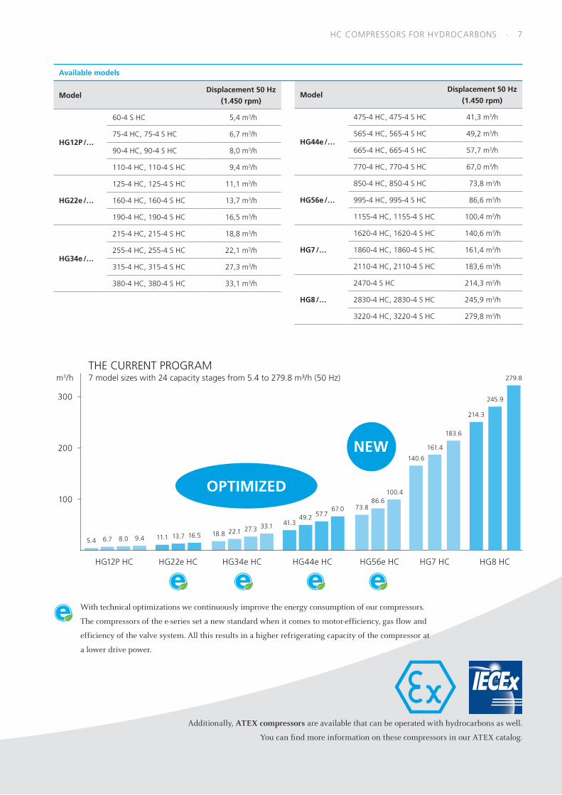
6 · HC COMPRESSORS FOR HYDROCARBONS
1 Oil sump heater (neccessary)
2 Thermal protection thermostat (recommended)
3 Special oil charge
4 Durable driving gear for demanding applications with hydrocarbons
5 Electronic motor protection INT69 G enclosed for installation in the switch cabinet
1.
2
4
DIFFERENCES TO A STANDARD COMPRESSOR
3
5
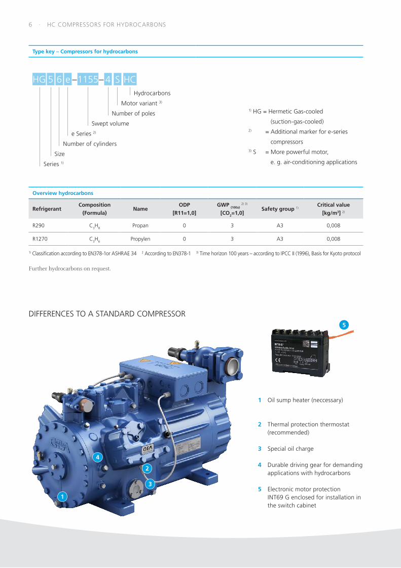
Type key – Compressors for hydrocarbons
Series 1)
65 HC1155
Size
Number of cylinders
e Series 2)
Swept volume
Number of poles
Motor variant 3)
–HG e – 4 SHydrocarbons
1) HG = Hermetic Gas-cooled
(suction-gas-cooled)2) = Additional marker for e-series
compressors3) S = More powerful motor,
e. g. air-conditioning applications
Overview hydrocarbons
RefrigerantComposition
(Formula)Name
ODP
[R11=1,0]
GWP (100a) 2) 3)
[CO2=1,0]Safety group 1)
Critical value
[kg/m3] 2)
R290 C3H8 Propan 0 3 A3 0,008
R1270 C3H6 Propylen 0 3 A3 0,008
1) Classification according to EN378-1or ASHRAE 34 2 According to EN378-1 3) Time horizon 100 years – according to IPCC II (1996), Basis for Kyoto protocol
Further hydrocarbons on request.
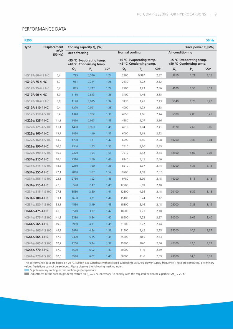
HC COMPRESSORS FOR HYDROCARBONS · 7
ModelDisplacement 50 Hz
(1.450 rpm)
HG12P /…
60-4 S HC 5,4 m3/h
75-4 HC, 75-4 S HC 6,7 m3/h
90-4 HC, 90-4 S HC 8,0 m3/h
110-4 HC, 110-4 S HC 9,4 m3/h
HG22e /…
125-4 HC, 125-4 S HC 11,1 m3/h
160-4 HC, 160-4 S HC 13,7 m3/h
190-4 HC, 190-4 S HC 16,5 m3/h
HG34e /…
215-4 HC, 215-4 S HC 18,8 m3/h
255-4 HC, 255-4 S HC 22,1 m3/h
315-4 HC, 315-4 S HC 27,3 m3/h
380-4 HC, 380-4 S HC 33,1 m3/h
ModelDisplacement 50 Hz
(1.450 rpm)
HG44e /…
475-4 HC, 475-4 S HC 41,3 m3/h
565-4 HC, 565-4 S HC 49,2 m3/h
665-4 HC, 665-4 S HC 57,7 m3/h
770-4 HC, 770-4 S HC 67,0 m3/h
HG56e /…
850-4 HC, 850-4 S HC 73,8 m3/h
995-4 HC, 995-4 S HC 86,6 m3/h
1155-4 HC, 1155-4 S HC 100,4 m3/h
HG7 /…
1620-4 HC, 1620-4 S HC 140,6 m3/h
1860-4 HC, 1860-4 S HC 161,4 m3/h
2110-4 HC, 2110-4 S HC 183,6 m3/h
HG8 /…
2470-4 S HC 214,3 m3/h
2830-4 HC, 2830-4 S HC 245,9 m3/h
3220-4 HC, 3220-4 S HC 279,8 m3/h
Available models
NEW
OPTIMIZED
300
200
100
5.4 11.16.7 13.78.0 16.59.418.8
41.322.1
49.2
27.3
57.773.8
33.1
67.086.6
m3/hTHE CURRENT PROGRAM7 model sizes with 24 capacity stages from 5.4 to 279.8 m³/h (50 Hz)
100.4
HG12P HC HG22e HC HG34e HC HG44e HC HG56e HC
140.6
161.4
183.6
245.9
214.3
279.8
HG8 HCHG7 HC
Additionally, ATEX compressors are available that can be operated with hydrocarbons as well.
You can find more information on these compressors in our ATEX catalog.
With technical optimizations we continuously improve the energy consumption of our compressors.
The compressors of the e-series set a new standard when it comes to motor-efficiency, gas flow and
efficiency of the valve system. All this results in a higher refrigerating capacity of the compressor at
a lower drive power.

8 · HC COMPRESSORS FOR HYDROCARBONS
R290 Operating Limits
HG… -4
70
60
50
40
30
20
10
–5–15–25–35–40 –10–20–30
∆t0h+20 °C∆t0h<20K
t0 (°C)
tC (°C) HG… -4 S
70
60
50
40
30
20
10
10–40 0–10–20–30
∆t0h+20 °C ∆t0h≥20 K∆t0h<20K
t0 (°C)
tC (°C)
Diagrams for other areas available on request
The use of other hydrocarbons is permitted only
following prior written approval from GEA Bock
tO Evaporating temperature (°C)
tC Condensing temperature (°C)
∆tOh Suction gas superheat (K)
tOh Suction gas temperature (°C)
Required minimum superheat ∆tOh = 20 K
Required minimum superheat ∆tOh = 20 K, the
suction gas temperature has to be adapted accordingly
Supplementary cooling or reduced suction gas temperature (∆tOh < 20 K)
Supplementary cooling and reduced suction gas temperature (∆tOh < 20 K)
Max. permissible operating pressure (LP/HP) 1): 19/28 bar1) LP = low pressure, HP = high pressure
Notes
Operating limits
Compressor operation is possible within the limits shown on the
application diagrams. Please note the coloured areas. the dark
blue and gray application area a minimum superheat ∆tOh = 20 K
must be applied. If necessary there must be planned an internal heat
exchanger IHX. Compressor application limits should not be chosen
for design purposes or continuous operation.
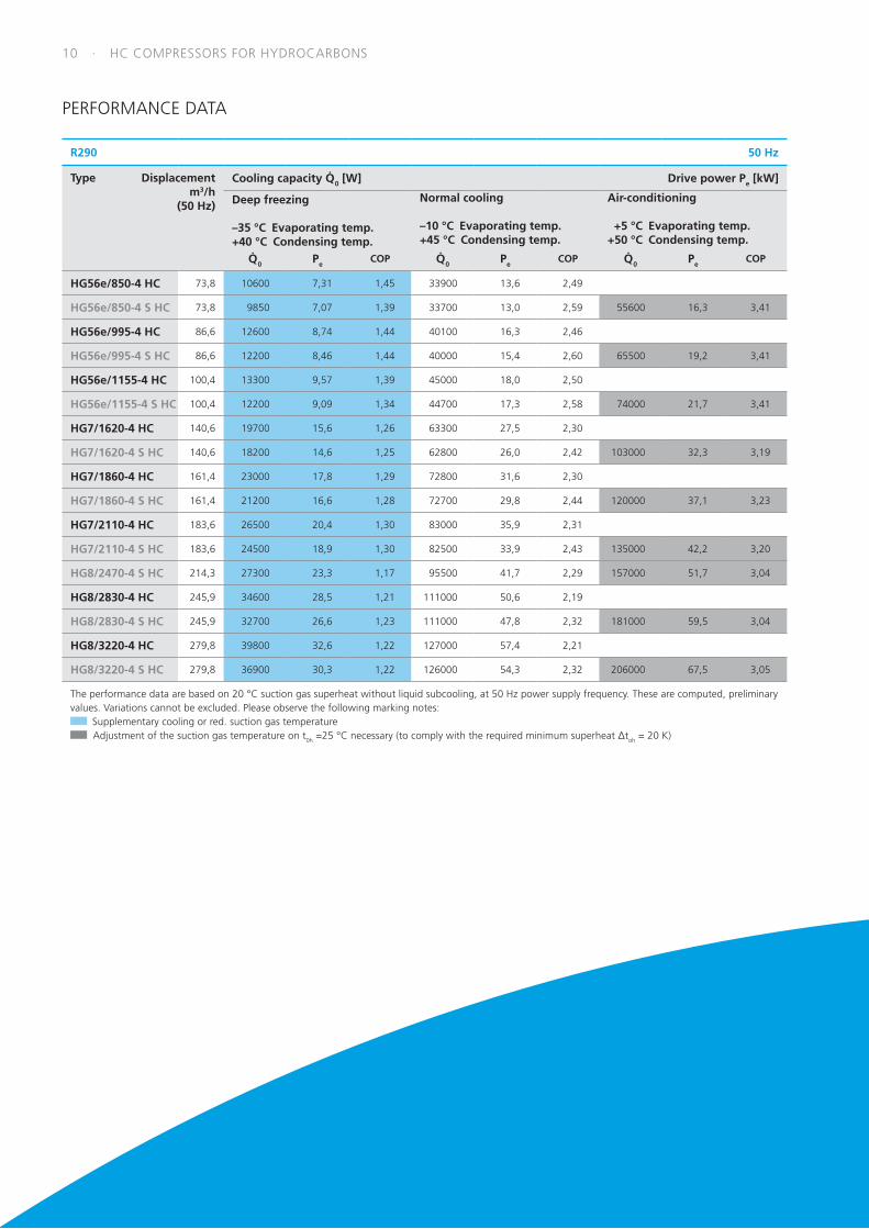
Performance data
The performance data are based on 20 °C suction gas superheat
without liquid subcooling, at 50 Hz power supply frequency. These
are computed, preliminary values. Variations cannot be excluded.
Please follow the notes to the suction gas superheat.
Conversion factor for 60 Hz = 1,2
Further information can be found online at vap.gea.com
OPERATING LIMITS
HC COMPRESSORS FOR HYDROCARBONS · 9
R290 50 Hz
Type Displacement m3/h (50 Hz)
Cooling capacity Q 0 [W] Drive power Pe [kW]
Deep freezing
–35 °C Evaporating temp. +40 °C Condensing temp.
Normal cooling
–10 °C Evaporating temp. +45 °C Condensing temp.
Air-conditioning
+5 °C Evaporating temp. +50 °C Condensing temp.
Q 0 PeCOP Q 0 Pe
COP Q 0 PeCOP
HG12P/60-4 S HC 5,4 725 0,586 1,24 2360 0,997 2,37 3810 1,21 3,15
HG12P/75-4 HC 6,7 911 0,724 1,26 2830 1,22 2,32
HG12P/75-4 S HC 6,7 885 0,727 1,22 2900 1,23 2,36 4670 1,50 3,11
HG12P/90-4 HC 8,0 1150 0,843 1,36 3400 1,46 2,33
HG12P/90-4 S HC 8,0 1120 0,835 1,34 3430 1,41 2,43 5540 1,73 3,20
HG12P/110-4 HC 9,4 1370 0,991 1,38 4000 1,72 2,33
HG12P/110-4 S HC 9,4 1340 0,982 1,36 4050 1,66 2,44 6500 2,03 3,20
HG22e/125-4 HC 11,1 1430 0,923 1,55 4880 2,07 2,36
HG22e/125-4 S HC 11,1 1400 0,963 1,45 4910 2,04 2,41 8170 2,68 3,05
HG22e/160-4 HC 13,7 1820 1,19 1,53 6090 2,63 2,32
HG22e/160-4 S HC 13,7 1780 1,21 1,47 6090 2,56 2,38 10200 3,35 3,04
HG22e/190-4 HC 16,5 2340 1,53 1,53 7510 3,20 2,35
HG22e/190-4 S HC 16,5 2320 1,54 1,51 7610 3,12 2,44 12500 4,06 3,08
HG34e/215-4 HC 18,8 2310 1,56 1,48 8140 3,45 2,36
HG34e/215-4 S HC 18,8 2210 1,60 1,38 8210 3,37 2,44 13700 4,38 3,13
HG34e/255-4 HC 22,1 2840 1,87 1,52 9700 4,09 2,37
HG34e/255-4 S HC 22,1 2780 1,92 1,45 9780 3,99 2,45 16200 5,18 3,13
HG34e/315-4 HC 27,3 3590 2,47 1,45 12200 5,09 2,40
HG34e/315-4 S HC 27,3 3530 2,50 1,41 12300 4,95 2,48 20100 6,32 3,18
HG34e/380-4 HC 33,1 4630 3,21 1,44 15100 6,24 2,42
HG34e/380-4 S HC 33,1 4550 3,19 1,43 15300 6,16 2,48 25000 7,83 3,19
HG44e/475-4 HC 41,3 5540 3,77 1,47 18500 7,71 2,40
HG44e/475-4 S HC 41,3 5380 3,84 1,40 18600 7,23 2,57 30700 9,02 3,40
HG44e/565-4 HC 49,2 5950 4,11 1,45 21300 8,72 2,44
HG44e/565-4 S HC 49,2 5910 4,24 1,39 21500 8,42 2,55 35700 10,6 3,37
HG44e/665-4 HC 57,7 7420 5,15 1,44 25500 10,5 2,43
HG44e/665-4 S HC 57,7 7200 5,24 1,37 25600 10,0 2,56 42100 12,5 3,37
HG44e/770-4 HC 67,0 8590 6,02 1,43 30000 11,6 2,59
HG44e/770-4 S HC 67,0 8590 6,02 1,43 30000 11,6 2,59 49500 14,6 3,39
The performance data are based on 20 °C suction gas superheat without liquid subcooling, at 50 Hz power supply frequency. These are computed, preliminary values. Variations cannot be excluded. Please observe the following marking notes:
Supplementary cooling or red. suction gas temperature Adjustment of the suction gas temperature on t0h =25 °C necessary (to comply with the required minimum superheat Δtoh = 20 K)
PERFORMANCE DATA
10 · HC COMPRESSORS FOR HYDROCARBONS
R290 50 Hz
Type Displacement m3/h (50 Hz)
Cooling capacity Q 0 [W] Drive power Pe [kW]
Deep freezing
–35 °C Evaporating temp. +40 °C Condensing temp.
Normal cooling
–10 °C Evaporating temp. +45 °C Condensing temp.
Air-conditioning
+5 °C Evaporating temp. +50 °C Condensing temp.
Q 0 PeCOP Q 0 Pe
COP Q 0 PeCOP
HG56e/850-4 HC 73,8 10600 7,31 1,45 33900 13,6 2,49
HG56e/850-4 S HC 73,8 9850 7,07 1,39 33700 13,0 2,59 55600 16,3 3,41
HG56e/995-4 HC 86,6 12600 8,74 1,44 40100 16,3 2,46
HG56e/995-4 S HC 86,6 12200 8,46 1,44 40000 15,4 2,60 65500 19,2 3,41
HG56e/1155-4 HC 100,4 13300 9,57 1,39 45000 18,0 2,50
HG56e/1155-4 S HC 100,4 12200 9,09 1,34 44700 17,3 2,58 74000 21,7 3,41
HG7/1620-4 HC 140,6 19700 15,6 1,26 63300 27,5 2,30
HG7/1620-4 S HC 140,6 18200 14,6 1,25 62800 26,0 2,42 103000 32,3 3,19
HG7/1860-4 HC 161,4 23000 17,8 1,29 72800 31,6 2,30
HG7/1860-4 S HC 161,4 21200 16,6 1,28 72700 29,8 2,44 120000 37,1 3,23
HG7/2110-4 HC 183,6 26500 20,4 1,30 83000 35,9 2,31
HG7/2110-4 S HC 183,6 24500 18,9 1,30 82500 33,9 2,43 135000 42,2 3,20
HG8/2470-4 S HC 214,3 27300 23,3 1,17 95500 41,7 2,29 157000 51,7 3,04
HG8/2830-4 HC 245,9 34600 28,5 1,21 111000 50,6 2,19
HG8/2830-4 S HC 245,9 32700 26,6 1,23 111000 47,8 2,32 181000 59,5 3,04
HG8/3220-4 HC 279,8 39800 32,6 1,22 127000 57,4 2,21
HG8/3220-4 S HC 279,8 36900 30,3 1,22 126000 54,3 2,32 206000 67,5 3,05
The performance data are based on 20 °C suction gas superheat without liquid subcooling, at 50 Hz power supply frequency. These are computed, preliminary values. Variations cannot be excluded. Please observe the following marking notes:
Supplementary cooling or red. suction gas temperature Adjustment of the suction gas temperature on t0h =25 °C necessary (to comply with the required minimum superheat Δtoh = 20 K)
PERFORMANCE DATA
HC COMPRESSORS FOR HYDROCARBONS · 11
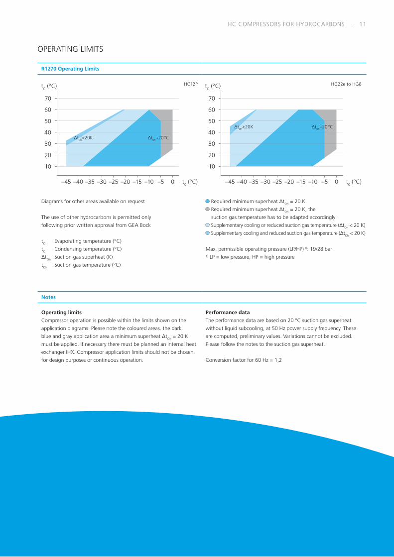
R1270 Operating Limits
HG12P
70
60
50
40
30
20
10
–45 –40 0–5–15 –10–25 –20–35 –30
∆t0h+20 °C∆t0h<20K
t0 (°C)
tC (°C) HG22e to HG8
70
60
50
40
30
20
10
–45 –40 0–5–15 –10–25 –20–35 –30
∆t0h+20 °C∆t0h<20K
t0 (°C)
tC (°C)
Diagrams for other areas available on request
The use of other hydrocarbons is permitted only
following prior written approval from GEA Bock
tO Evaporating temperature (°C)
tC Condensing temperature (°C)
∆tOh Suction gas superheat (K)
tOh Suction gas temperature (°C)
Required minimum superheat ∆tOh = 20 K
Required minimum superheat ∆tOh = 20 K, the
suction gas temperature has to be adapted accordingly
Supplementary cooling or reduced suction gas temperature (∆tOh < 20 K)
Supplementary cooling and reduced suction gas temperature (∆tOh < 20 K)
Max. permissible operating pressure (LP/HP) 1): 19/28 bar1) LP = low pressure, HP = high pressure
Notes
Operating limits
Compressor operation is possible within the limits shown on the
application diagrams. Please note the coloured areas. the dark
blue and gray application area a minimum superheat ∆tOh = 20 K
must be applied. If necessary there must be planned an internal heat
exchanger IHX. Compressor application limits should not be chosen
for design purposes or continuous operation.
Performance data
The performance data are based on 20 °C suction gas superheat
without liquid subcooling, at 50 Hz power supply frequency. These
are computed, preliminary values. Variations cannot be excluded.
Please follow the notes to the suction gas superheat.
Conversion factor for 60 Hz = 1,2
OPERATING LIMITS
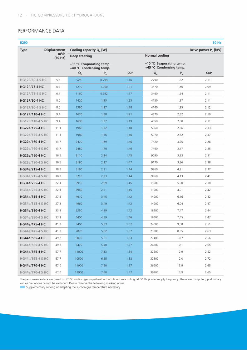
12 · HC COMPRESSORS FOR HYDROCARBONS
R290 50 Hz
Type Displacement m3/h (50 Hz)
Cooling capacity Q 0 [W] Drive power Pe [kW]
Deep freezing
–35 °C Evaporating temp. +40 °C Condensing temp.
Normal cooling
–10 °C Evaporating temp. +45 °C Condensing temp.
Q 0 PeCOP Q 0 Pe
COP
HG12P/60-4 S HC 5,4 925 0,794 1,16 2790 1,32 2,11
HG12P/75-4 HC 6,7 1210 1,000 1,21 3470 1,66 2,09
HG12P/75-4 S HC 6,7 1160 0,992 1,17 3460 1,64 2,11
HG12P/90-4 HC 8,0 1420 1,15 1,23 4150 1,97 2,11
HG12P/90-4 S HC 8,0 1380 1,17 1,18 4140 1,95 2,12
HG12P/110-4 HC 9,4 1670 1,38 1,21 4870 2,32 2,10
HG12P/110-4 S HC 9,4 1630 1,37 1,19 4850 2,30 2,11
HG22e/125-4 HC 11,1 1960 1,32 1,48 5960 2,56 2,33
HG22e/125-4 S HC 11,1 1980 1,36 1,46 5970 2,52 2,37
HG22e/160-4 HC 13,7 2470 1,69 1,46 7420 3,25 2,28
HG22e/160-4 S HC 13,7 2480 1,70 1,46 7450 3,17 2,35
HG22e/190-4 HC 16,5 3110 2,14 1,45 9090 3,93 2,31
HG22e/190-4 S HC 16,5 3180 2,17 1,47 9170 3,86 2,38
HG34e/215-4 HC 18,8 3190 2,21 1,44 9960 4,21 2,37
HG34e/215-4 S HC 18,8 3210 2,23 1,44 9960 4,13 2,41
HG34e/255-4 HC 22,1 3910 2,69 1,45 11900 5,00 2,38
HG34e/255-4 S HC 22,1 3940 2,71 1,45 11900 4,91 2,42
HG34e/315-4 HC 27,3 4910 3,45 1,42 14900 6,16 2,42
HG34e/315-4 S HC 27,3 4960 3,49 1,42 14900 6,04 2,47
HG34e/380-4 HC 33,1 6250 4,39 1,42 18200 7,47 2,44
HG34e/380-4 S HC 33,1 6400 4,39 1,46 18400 7,45 2,47
HG44e/475-4 HC 41,3 8400 5,53 1,52 24000 9,58 2,51
HG44e/475-4 S HC 41,3 7870 5,02 1,57 23300 8,85 2,63
HG44e/565-4 HC 49,2 9070 5,91 1,53 27400 10,7 2,56
HG44e/565-4 S HC 49,2 8470 5,40 1,57 26800 10,1 2,65
HG44e/665-4 HC 57,7 11000 7,13 1,54 32500 12,9 2,52
HG44e/665-4 S HC 57,7 10500 6,65 1,58 32600 12,0 2,72
HG44e/770-4 HC 67,0 11900 7,60 1,57 36900 13,9 2,65
HG44e/770-4 S HC 67,0 11900 7,60 1,57 36900 13,9 2,65
The performance data are based on 20 °C suction gas superheat without liquid subcooling, at 50 Hz power supply frequency. These are computed, preliminary values. Variations cannot be excluded. Please observe the following marking notes:
Supplementary cooling or adapting the suction gas temperature necessary
PERFORMANCE DATA
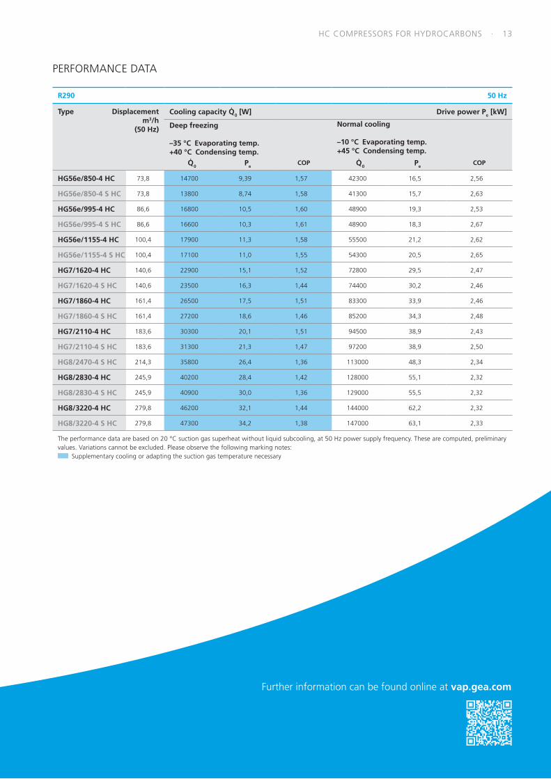
HC COMPRESSORS FOR HYDROCARBONS · 13
Further information can be found online at vap.gea.com
R290 50 Hz
Type Displacement m3/h (50 Hz)
Cooling capacity Q 0 [W] Drive power Pe [kW]
Deep freezing
–35 °C Evaporating temp. +40 °C Condensing temp.
Normal cooling
–10 °C Evaporating temp. +45 °C Condensing temp.
Q 0 PeCOP Q 0 Pe
COP
HG56e/850-4 HC 73,8 14700 9,39 1,57 42300 16,5 2,56
HG56e/850-4 S HC 73,8 13800 8,74 1,58 41300 15,7 2,63
HG56e/995-4 HC 86,6 16800 10,5 1,60 48900 19,3 2,53
HG56e/995-4 S HC 86,6 16600 10,3 1,61 48900 18,3 2,67
HG56e/1155-4 HC 100,4 17900 11,3 1,58 55500 21,2 2,62
HG56e/1155-4 S HC 100,4 17100 11,0 1,55 54300 20,5 2,65
HG7/1620-4 HC 140,6 22900 15,1 1,52 72800 29,5 2,47
HG7/1620-4 S HC 140,6 23500 16,3 1,44 74400 30,2 2,46
HG7/1860-4 HC 161,4 26500 17,5 1,51 83300 33,9 2,46
HG7/1860-4 S HC 161,4 27200 18,6 1,46 85200 34,3 2,48
HG7/2110-4 HC 183,6 30300 20,1 1,51 94500 38,9 2,43
HG7/2110-4 S HC 183,6 31300 21,3 1,47 97200 38,9 2,50
HG8/2470-4 S HC 214,3 35800 26,4 1,36 113000 48,3 2,34
HG8/2830-4 HC 245,9 40200 28,4 1,42 128000 55,1 2,32
HG8/2830-4 S HC 245,9 40900 30,0 1,36 129000 55,5 2,32
HG8/3220-4 HC 279,8 46200 32,1 1,44 144000 62,2 2,32
HG8/3220-4 S HC 279,8 47300 34,2 1,38 147000 63,1 2,33
The performance data are based on 20 °C suction gas superheat without liquid subcooling, at 50 Hz power supply frequency. These are computed, preliminary values. Variations cannot be excluded. Please observe the following marking notes:
Supplementary cooling or adapting the suction gas temperature necessary
PERFORMANCE DATA
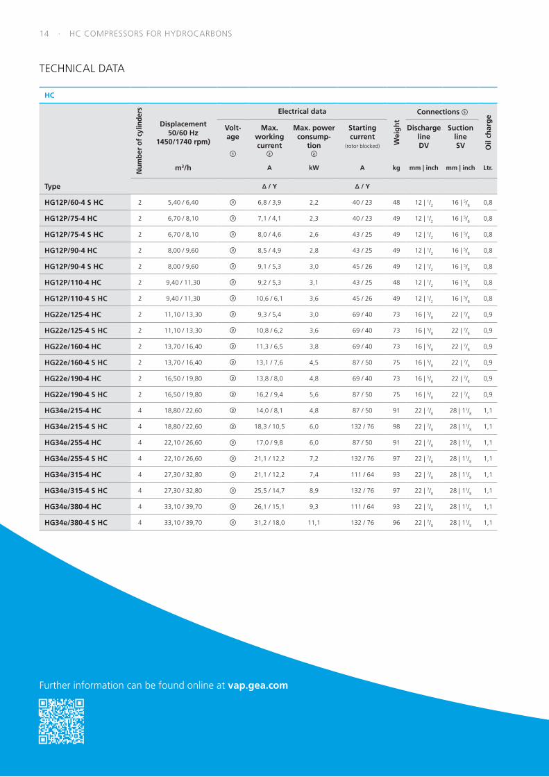
14 · HC COMPRESSORS FOR HYDROCARBONS
HC
Num
ber
of c
ylin
ders
Displacement50/60 Hz
1450/1740 rpm)
Electrical data
Wei
gh
t
Connections 5
Oil
char
ge
Volt-age
1
Max.workingcurrent
2
Max. powerconsump-
tion2
Startingcurrent
(rotor blocked)
DischargelineDV
SuctionlineSV
m3/h A kW A kg mm | inch mm | inch Ltr.
Type ∆ / Y ∆ / Y
HG12P/60-4 S HC 2 5,40 / 6,40 3 6,8 / 3,9 2,2 40 / 23 48 12 | 1/2 16 | 5/8 0,8
HG12P/75-4 HC 2 6,70 / 8,10 3 7,1 / 4,1 2,3 40 / 23 49 12 | 1/2 16 | 5/8 0,8
HG12P/75-4 S HC 2 6,70 / 8,10 3 8,0 / 4,6 2,6 43 / 25 49 12 | 1/2 16 | 5/8 0,8
HG12P/90-4 HC 2 8,00 / 9,60 3 8,5 / 4,9 2,8 43 / 25 49 12 | 1/2 16 | 5/8 0,8
HG12P/90-4 S HC 2 8,00 / 9,60 3 9,1 / 5,3 3,0 45 / 26 49 12 | 1/2 16 | 5/8 0,8
HG12P/110-4 HC 2 9,40 / 11,30 3 9,2 / 5,3 3,1 43 / 25 48 12 | 1/2 16 | 5/8 0,8
HG12P/110-4 S HC 2 9,40 / 11,30 3 10,6 / 6,1 3,6 45 / 26 49 12 | 1/2 16 | 5/8 0,8
HG22e/125-4 HC 2 11,10 / 13,30 3 9,3 / 5,4 3,0 69 / 40 73 16 | 5/8 22 | 7/8 0,9
HG22e/125-4 S HC 2 11,10 / 13,30 3 10,8 / 6,2 3,6 69 / 40 73 16 | 5/8 22 | 7/8 0,9
HG22e/160-4 HC 2 13,70 / 16,40 3 11,3 / 6,5 3,8 69 / 40 73 16 | 5/8 22 | 7/8 0,9
HG22e/160-4 S HC 2 13,70 / 16,40 3 13,1 / 7,6 4,5 87 / 50 75 16 | 5/8 22 | 7/8 0,9
HG22e/190-4 HC 2 16,50 / 19,80 3 13,8 / 8,0 4,8 69 / 40 73 16 | 5/8 22 | 7/8 0,9
HG22e/190-4 S HC 2 16,50 / 19,80 3 16,2 / 9,4 5,6 87 / 50 75 16 | 5/8 22 | 7/8 0,9
HG34e/215-4 HC 4 18,80 / 22,60 3 14,0 / 8,1 4,8 87 / 50 91 22 | 7/8 28 | 11/8 1,1
HG34e/215-4 S HC 4 18,80 / 22,60 3 18,3 / 10,5 6,0 132 / 76 98 22 | 7/8 28 | 11/8 1,1
HG34e/255-4 HC 4 22,10 / 26,60 3 17,0 / 9,8 6,0 87 / 50 91 22 | 7/8 28 | 11/8 1,1
HG34e/255-4 S HC 4 22,10 / 26,60 3 21,1 / 12,2 7,2 132 / 76 97 22 | 7/8 28 | 11/8 1,1
HG34e/315-4 HC 4 27,30 / 32,80 3 21,1 / 12,2 7,4 111 / 64 93 22 | 7/8 28 | 11/8 1,1
HG34e/315-4 S HC 4 27,30 / 32,80 3 25,5 / 14,7 8,9 132 / 76 97 22 | 7/8 28 | 11/8 1,1
HG34e/380-4 HC 4 33,10 / 39,70 3 26,1 / 15,1 9,3 111 / 64 93 22 | 7/8 28 | 11/8 1,1
HG34e/380-4 S HC 4 33,10 / 39,70 3 31,2 / 18,0 11,1 132 / 76 96 22 | 7/8 28 | 11/8 1,1
Further information can be found online at vap.gea.com
TECHNICAL DATA

HC COMPRESSORS FOR HYDROCARBONS · 15
HC
Num
ber
of c
ylin
ders
Displacement50/60 Hz
1450/1740 rpm)
Electrical data
Wei
gh
t
Connections 5
Oil
char
ge
Volt-age
1
Max.workingcurrent
2
Max. powerconsump-
tion2
Startingcurrent
(rotor blocked)
DischargelineDV
SuctionlineSV
m3/h A kW A kg mm | inch mm | inch Ltr.
Type *PW 1+2 *PW1/PW 1+2
HG44e/475-4 HC 4 41,30 / 49,60 4 19,0 11,0 65 / 109 166 28 I 11/8 35 I 13/8 2,3
HG44e/475-4 S HC 4 41,30 / 49,60 4 23,0 13,1 87 / 149 171 28 I 11/8 35 I 13/8 2,3
HG44e/565-4 HC 4 49,20 / 59,00 4 22,0 13,2 65 / 109 166 28 I 11/8 35 I 13/8 2,3
HG44e/565-4 S HC 4 49,20 / 59,00 4 26,0 15,6 101 / 174 173 28 I 11/8 42 I 15/8 2,3
HG44e/665-4 HC 4 57,70 / 69,20 4 26,0 15,4 87 / 149 174 28 I 11/8 42 I 15/8 2,3
HG44e/665-4 S HC 4 57,70 / 69,20 4 30,0 18,3 101 / 174 171 28 I 11/8 42 I 15/8 2,3
HG44e/770-4 HC 4 67,00 / 80,40 4 30,0 17,8 101 / 174 171 28 I 11/8 42 I 15/8 2,3
HG44e/770-4 S HC 4 67,00 / 80,40 4 35,0 21,4 101 / 174 171 28 I 11/8 42 I 15/8 2,3
HG56e/850-4 HC 6 73,80 / 88,60 4 32,6 19,7 101 / 174 195 35 I 13/8 54 I 21/8 2,7
HG56e/850-4 S HC 6 73,80 / 88,60 4 39,4 23,5 125 / 209 212 35 I 13/8 54 I 21/8 2,7
HG56e/995-4 HC 6 86,60 / 103,90 4 38,9 23,2 125 / 209 209 35 I 13/8 54 I 21/8 2,7
HG56e/995-4 S HC 6 86,60 / 103,90 4 46,4 27,7 149 / 246 212 35 I 13/8 54 I 21/8 2,7
HG56e/1155-4 HC 6 100,40 / 120,50 4 46,9 28,0 149 / 246 213 35 I 13/8 54 I 21/8 2,7
HG56e/1155-4 S HC 6 100,40 / 120,50 4 58,3 33,3 196 / 335 221 35 I 13/8 54 I 21/8 2,7
HG7/1620-4 HC 6 140,60 / 168,70 4 72,0 39,5 223 / 340 279 42 I 15/8 54 I 21/8 4,5
HG7/1620-4 S HC 6 140,60 / 168,70 4 83,0 47,4 268 / 373 300 42 I 15/8 54 I 21/8 4,5
HG7/1860-4 HC 6 161,40 / 193,70 4 80,0 45,8 268 / 373 297 42 I 15/8 54 I 21/8 4,5
HG7/1860-4 S HC 6 161,40 / 193,70 4 104,0 56,7 291 / 429 293 42 I 15/8 54 I 21/8 4,5
HG7/2110-4 HC 6 183,60 / 220,40 4 97,0 53,1 291 / 429 290 42 I 15/8 64 I 25/8 4,5
HG7/2110-4 S HC 6 183,60 / 220,40 4 119,0 65,6 344 / 500 298 42 I 15/8 64 I 25/8 4,5
HG8/2470-4 S HC 8 214,30 / 257,10 4 133,2 76,1 447 / 657 423 54 I 21/8 76 I 31/8 9,0
HG8/2830-4 HC 8 245,90 / 295,10 4 135,6 79,0 386 / 567 420 54 I 21/8 76 I 31/8 9,0
HG8/2830-4 S HC 8 245,90 / 295,10 4 151,6 88,1 447 / 657 440 54 I 21/8 76 I 31/8 9,0
HG8/3220-4 HC 8 279,80 / 335,80 4 144,6 83,6 447 / 657 414 54 I 21/8 76 I 31/8 9,0
HG8/3220-4 S HC 8 279,80 / 335,80 4 175,6 101,4 538 / 791 434 54 I 21/8 76 I 31/8 9,0
* PW = Part Winding, motors for part winding start 1 = 1. part winding 2 = 2. part winding
TECHNICAL DATA

16 · HC COMPRESSORS FOR HYDROCARBONS
Explanations:
1 Toleranz (± 10%) relates to the mean value of the voltage range.
Other voltages and current types on request.
2 • The specifications for max. power consumption apply for
50 Hz operation. For 60 Hz operation, the specifications have to
be multiplied by the factor 1.2.
The max. working current remains unchanged.
• Take account of the max. operating current / max. power
consumption when designing contactors, leads and fuses
Switches: service category AC3
3 220-240 V ∆ / 380-420 V Y - 3 - 50 Hz
265-290 V ∆ / 440-480 V Y - 3 - 60 Hz
4 380-420 V Y/YY - 3 - 50 Hz PW
440-480 V Y/YY - 3 - 60 Hz PW
PW = Part Winding, motors for part winding start
(no start unloaders required)
Winding ratio: HG44e, HG56e, HG7, HG8 = 50% / 50%
Designs for Y/∆ on request
5 For soldering connections
Oil sump heater 110-240 V - 1 - 50/60 Hz (Option)
HG12P..HC, HG22e..HC, HG34e..HC: 50-120 W
PTC heater, self-regulating, installation in housing bore
Oil sump heater 230 V - 1 - 50/60 Hz (Option)
HG44e..HC: 80 W
HG56e...HC, HG7...HC: 140 W
HG8..HC: 200 W
Permanently set version, installation in immersion sleeve
TECHNICAL DATA
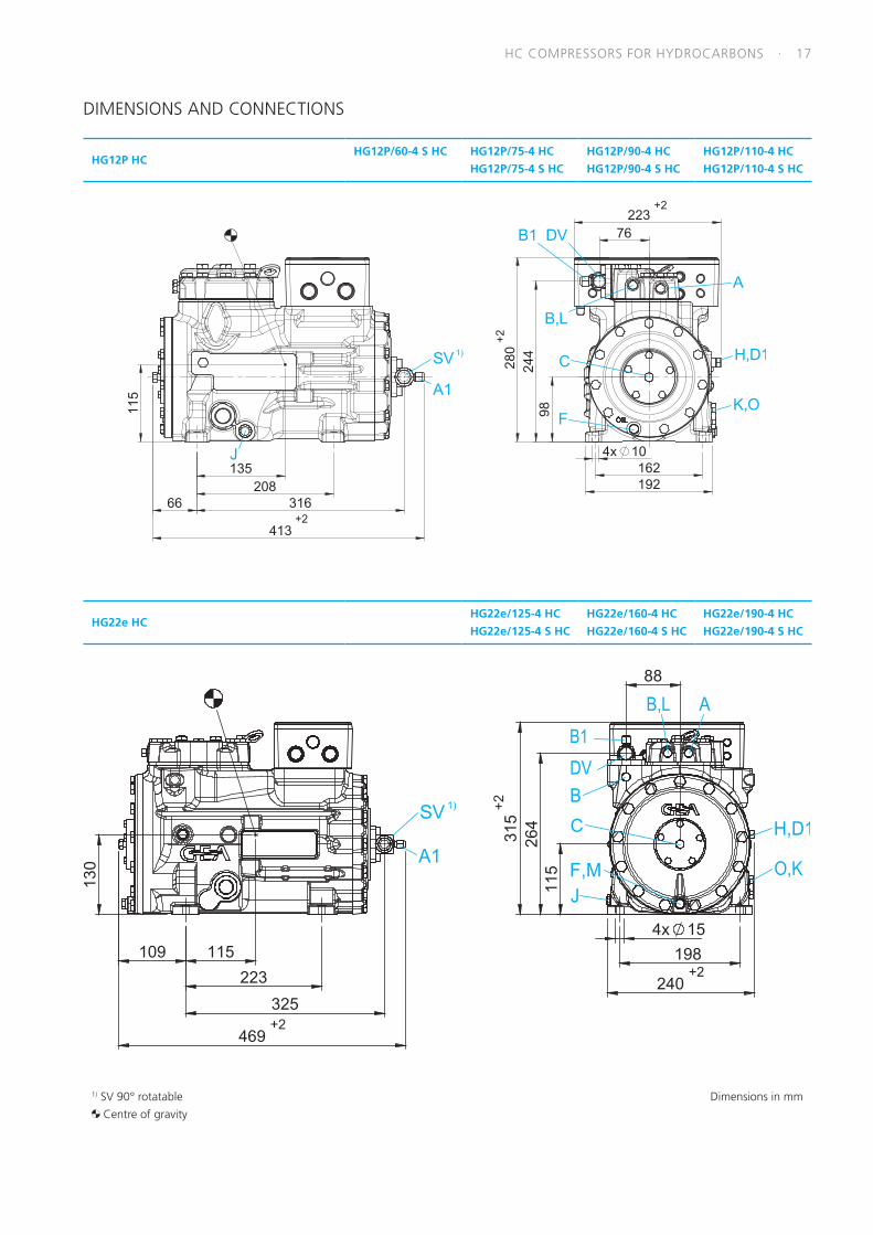
HC COMPRESSORS FOR HYDROCARBONS · 17
HG12P HCHG12P/60-4 S HC HG12P/75-4 HC
HG12P/75-4 S HC
HG12P/90-4 HC
HG12P/90-4 S HC
HG12P/110-4 HC
HG12P/110-4 S HC
413
1)
HG22e HCHG22e/125-4 HC
HG22e/125-4 S HC
HG22e/160-4 HC
HG22e/160-4 S HC
HG22e/190-4 HC
HG22e/190-4 S HC
1)
469
1) SV 90° rotatable
Centre of gravity
Dimensions in mm
DIMENSIONS AND CONNECTIONS
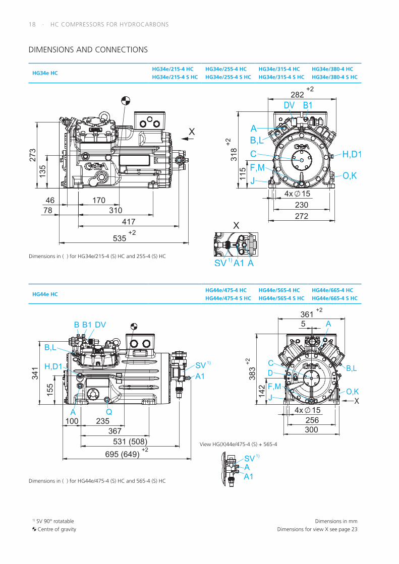
18 · HC COMPRESSORS FOR HYDROCARBONS
HG34e HCHG34e/215-4 HC
HG34e/215-4 S HC
HG34e/255-4 HC
HG34e/255-4 S HC
HG34e/315-4 HC
HG34e/315-4 S HC
HG34e/380-4 HC
HG34e/380-4 S HC
Dimensions in ( ) for HG34e/215-4 (S) HC and 255-4 (S) HC1)
HG44e HCHG44e/475-4 HC
HG44e/475-4 S HC
HG44e/565-4 HC
HG44e/565-4 S HC
HG44e/665-4 HC
HG44e/665-4 S HC
1)
1)
Dimensions in ( ) for HG44e/475-4 (S) HC and 565-4 (S) HC
View HG(X)44e/475-4 (S) + 565-4
1) SV 90° rotatable
Centre of gravity
Dimensions in mm
Dimensions for view X see page 23
DIMENSIONS AND CONNECTIONS
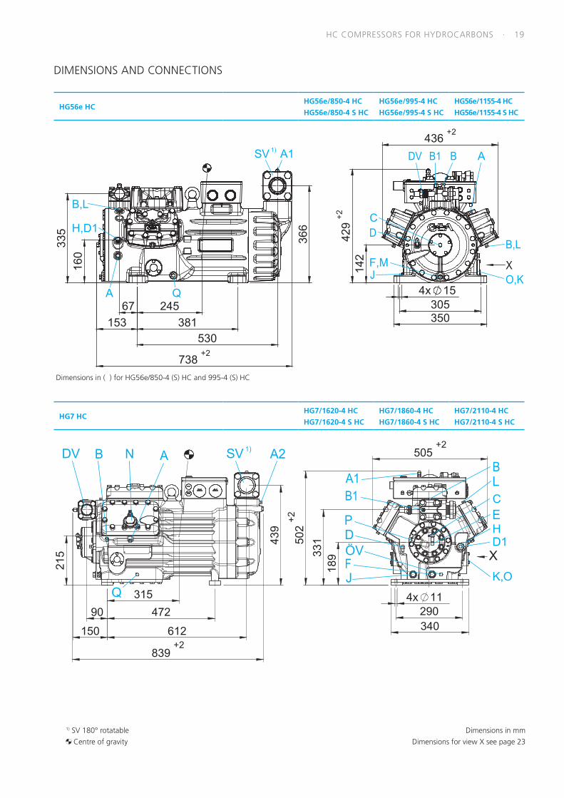
HC COMPRESSORS FOR HYDROCARBONS · 19
HG56e HCHG56e/850-4 HC
HG56e/850-4 S HC
HG56e/995-4 HC
HG56e/995-4 S HC
HG56e/1155-4 HC
HG56e/1155-4 S HC
Dimensions in ( ) for HG56e/850-4 (S) HC and 995-4 (S) HC
1)
HG7 HCHG7/1620-4 HC
HG7/1620-4 S HC
HG7/1860-4 HC
HG7/1860-4 S HC
HG7/2110-4 HC
HG7/2110-4 S HC
HD1
1)
1) SV 180° rotatable
Centre of gravity
Dimensions in mm
Dimensions for view X see page 23
DIMENSIONS AND CONNECTIONS

20 · HC COMPRESSORS FOR HYDROCARBONS
1) SV 180° rotatable
Centre of gravity
Dimensions in mm
Dimensions for view X see page 23
HG8 HC HG8/2470-4 S HCHG8/2830-4 HC
HG8/2830-4 S HC
HG8/3220-4 HC
HG8/3220-4 S HC
1)
View X
Possibility to connect oil level regulator
HG44e...HC, HG56e...HC, HG7...HC, HG8...HC
Three-hole connection for oil level regulator
make ESK, AC+R, CARLY (3x M6, 10 deep)
Three-hole connection for oil level regulator
make TRAXOIL (3 x M6 x 10 deep)
Dimensions in mm
124°
124°
124°
Ø 47,6
124°
DIMENSIONS AND CONNECTIONS
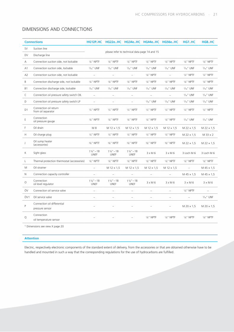
HC COMPRESSORS FOR HYDROCARBONS · 21
Connections HG12P..HC HG22e..HC HG34e..HC HG44e..HC HG56e..HC HG7..HC HG8..HC
SV Suction lineplease refer to technical data page 14 and 15
DV Discharge line
A Connection suction side, not lockable 1/8” NPTF 1/8” NPTF 1/8” NPTF 1/8” NPTF 1/8” NPTF 1/8” NPTF 1/8” NPTF
A1 Connection suction side, lockable 7/16” UNF 7/16” UNF 7/16” UNF 7/16” UNF 7/16” UNF 7/16” UNF 7/16” UNF
A2 Connection suction side, not lockable – – – 1/8” NPTF – 1/4” NPTF 1/4” NPTF
B Connection discharge side, not lockable 1/8” NPTF 1/8” NPTF 1/8” NPTF 1/8” NPTF 1/8” NPTF 1/8” NPTF 1/8” NPTF
B1 Connection discharge side, lockable 7/16” UNF 7/16” UNF 7/16” UNF 7/16” UNF 7/16” UNF 7/16” UNF 7/16” UNF
C Connection oil pressure safety switch OIL – – – – – 7/16” UNF 7/16” UNF
D Connection oil pressure safety switch LP – – – 7/16” UNF 7/16” UNF 7/16” UNF 7/16” UNF
D1Connection oil return from oil separator
1/4” NPTF 1/4” NPTF 1/4” NPTF 1/4” NPTF 1/4” NPTF 1/4” NPTF 1/4” NPTF
EConnectionoil pressure gauge
1/8” NPTF 1/8” NPTF 1/8” NPTF 1/8” NPTF 1/8” NPTF 7/16” UNF 7/16” UNF
F Oil drain M 8 M 12 × 1,5 M 12 × 1,5 M 12 × 1,5 M 12 × 1,5 M 22 × 1,5 M 22 × 1,5
H Oil charge plug 1/4” NPTF 1/4” NPTF 1/4” NPTF 1/4” NPTF 1/4” NPTF M 22 × 1,5 M 33 × 2
JOil sump heater (accessories)
3/8” NPTF 3/8” NPTF 3/8” NPTF 3/8” NPTF 3/8” NPTF M 22 × 1,5 M 22 × 1,5
K Sight glass 11/8” – 18 UNEF
11/8” – 18 UNEF
11/8” – 18 UNEF 3 x M 6 3 x M 6 3 Loch M 6 3 Loch M 6
L Thermal protection thermostat (accessories) 1/8” NPTF 1/8” NPTF 1/8” NPTF 1/8” NPTF 1/8” NPTF 1/8” NPTF 1/8” NPTF
M Oil strainer – M 12 × 1,5 M 12 × 1,5 M 12 × 1,5 M 12 × 1,5 – M 45 × 1,5
N Connection capacity controller – – – – – M 45 × 1,5 M 45 × 1,5
OConnection oil level regulator
11/8” – 18 UNEF
11/8” – 18 UNEF
11/8” – 18 UNEF 3 x M 6 3 x M 6 3 × M 6 3 × M 6
ÖV Connection oil service valve – – – – – 1/4” NPTF –
ÖV1 Oil service valve – – – – – – 7/16” UNF
PConnection oil differential
pressure sensor– – – – – M 20 × 1,5 M 20 × 1,5
QConnection
oil temperature sensor– – – 1/8” NPTF 1/8” NPTF 1/8” NPTF 1/8” NPTF
1) Dimensions see view X page 20
Attention
Electric, respectively electronic components of the standard extent of delivery, from the accessories or that are obtained otherwise have to be
handled and mounted in such a way that the corresponding regulations for the use of hydrocarbons are fulfilled.
DIMENSIONS AND CONNECTIONS
22 · HC COMPRESSORS FOR HYDROCARBONS
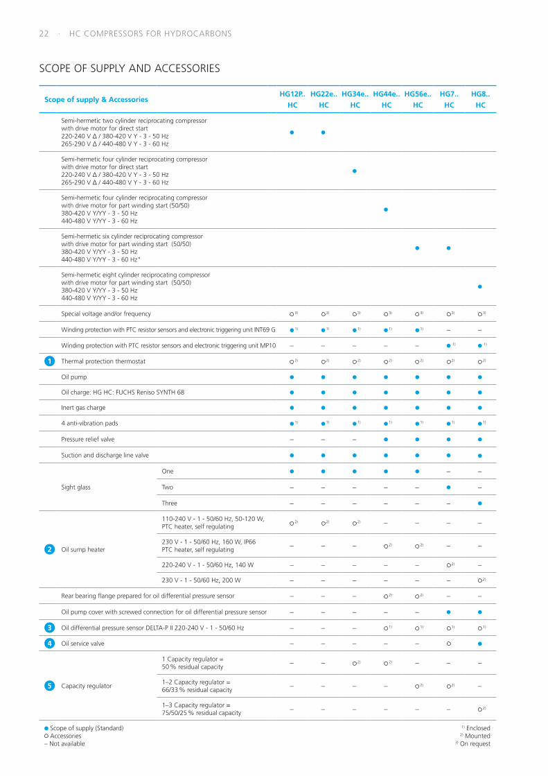
Scope of supply & AccessoriesHG12P..
HC
HG22e..
HC
HG34e..
HC
HG44e..
HC
HG56e..
HC
HG7..
HC
HG8..
HC
Semi-hermetic two cylinder reciprocating compressorwith drive motor for direct start220-240 V Δ / 380-420 V Y - 3 - 50 Hz265-290 V Δ / 440-480 V Y - 3 - 60 Hz
Semi-hermetic four cylinder reciprocating compressorwith drive motor for direct start220-240 V Δ / 380-420 V Y - 3 - 50 Hz265-290 V Δ / 440-480 V Y - 3 - 60 Hz
Semi-hermetic four cylinder reciprocating compressorwith drive motor for part winding start (50/50)380-420 V Y/YY - 3 - 50 Hz440-480 V Y/YY - 3 - 60 Hz
Semi-hermetic six cylinder reciprocating compressorwith drive motor for part winding start (50/50)380-420 V Y/YY - 3 - 50 Hz440-480 V Y/YY - 3 - 60 Hz"
Semi-hermetic eight cylinder reciprocating compressorwith drive motor for part winding start (50/50)380-420 V Y/YY - 3 - 50 Hz440-480 V Y/YY - 3 - 60 Hz
Special voltage and/or frequency 3) 3) 3) 3) 3) 3) 3)
Winding protection with PTC resistor sensors and electronic triggering unit INT69 G 1) 1) 1) 1) 1) – –
Winding protection with PTC resistor sensors and electronic triggering unit MP10 – – – – – 1) 1)
1 Thermal protection thermostat 2) 2) 2) 2) 2) 2) 2)
Oil pump
Oil charge: HG HC: FUCHS Reniso SYNTH 68
Inert gas charge
4 anti-vibration pads 1) 1) 1) 1) 1) 1) 1)
Pressure relief valve – – –
Suction and discharge line valve
Sight glass
One – –
Two – – – – – –
Three – – – – – –
2 Oil sump heater
110-240 V - 1 - 50/60 Hz, 50-120 W,PTC heater, self regulating 2) 2) 2) – – – –
230 V - 1 - 50/60 Hz, 160 W, IP66PTC heater, self regulating – – – 2) 2) – –
220-240 V - 1 - 50/60 Hz, 140 W – – – – – 2) –
230 V - 1 - 50/60 Hz, 200 W – – – – – – 2)
Rear bearing flange prepared for oil differential pressure sensor – – – 2) 2) – –
Oil pump cover with screwed connection for oil differential pressure sensor – – – – –
3 Oil differential pressure sensor DELTA-P II 220-240 V - 1 - 50/60 Hz – – – 1) 1) 1) 1)
4 Oil service valve – – – – –
5 Capacity regulator
1 Capacity regulator = 50 % residual capacity – – 2) 2) – – –
1–2 Capacity regulator = 66/33 % residual capacity – – – – 2) 2) –
1–3 Capacity regulator = 75/50/25 % residual capacity – – – – – – 2)
Scope of supply (Standard) Accessories
– Not available
1) Enclosed 2) Mounted 3) On request
SCOPE OF SUPPLY AND ACCESSORIES

HC COMPRESSORS FOR HYDROCARBONS · 23
Attention
Electric, respectively electronic components of the standard extent of delivery, from the accessories or that are obtained otherwise have to be
handled and mounted in such a way that the corresponding regulations for the use of hydrocarbons are fulfilled.
Scope of supply & AccessoriesHG12P..
HC
HG22e..
HC
HG34e..
HC
HG44e..
HC
HG56e..
HC
HG7..
HC
HG8..
HC
6 Prepared for capacity regulator
1 cylinder cover – – 2) 2) 2) 2) 2)
2 cylinder covers – – – – 2) 2) 2)
3 cylinder covers – – – – – – 2)
7 Oil temperature sensor – – – 2) 2) 2) 2)
8
Start unloader by means of a ESS (Electronic Soft Start)400 V - 3 - 50/60 Hz, IP20, (connection clamps IP00)for installation in switch cabinet
– 1) 1) 1) 1) 1) –
Start unloader 230 V - 1 - 50/60 Hz, IP65, without check valve,including thermal protection thermostat (PTC sensor) – – – – –
9 Connection piece suction and discharge valve in welded construction – – – 3) 3) 3) 3)
10
Additional fan 230 V - 1 - 50 Hz, 97 W, IP44,230- V - 1 - 60 Hz, 128 W,Voltage range ± 10%
1) 1) 1) 1) 1) 1) 1)
11 Intermediate flange for discharge line valve on right or left, seen from oil pump – – – 1) – – –
Intermediate adapter for discharge line valve – – – – –
12 INT69 G Diagnose 115 V / 230 V Ac, 50/60 Hz, IP00 (INT69 G not applicable) – 1) 1) 1) 1) – –
13 DP-Modbus Gateway 115 V / 230 V Ac, 50/60 Hz, IP00 incl. adapter cable – 1) 1) 1) 1) – –
14 Modbus-LAN Gateway 230 V Ac, 50/60 Hz, IP00 – 1) 1) 1) 1) – –
15 USB converter for INT69 G Diagnose – 1) 1) 1) 1) – –
Connection possibility of oil level controller makes ESK, AC+R oder CARLY 4) 4) 4)
Connection possibility of oil level controller make Traxoil 4) 4) 4) 4) 4) 4) 4)
Scope of supply (Standard) Accessories
– Not available
1) Enclosed 2) Mounted 3) On request 4) Only possible with additional adapter
SCOPE OF SUPPLY AND ACCESSORIES
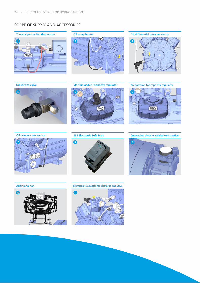
24 · HC COMPRESSORS FOR HYDROCARBONS
ESS Electronic Soft Start
8
Oil service valve
4
Additional fan
10
Oil temperature sensor
7
Connection piece in welded construction
9
Oil differential pressure sensor
3
Intermediate adapter for discharge line valve
11
Start unloader / Capacity regulator
5
Oil sump heater
2
Thermal protection thermostat
1
Preparation for capacity regulator
6
SCOPE OF SUPPLY AND ACCESSORIES

HC COMPRESSORS FOR HYDROCARBONS · 25
INT69 G Diagnose
USB converter
15
DP-Modbus Gateway
13
Modbus-LAN Gateway
14
SCOPE OF SUPPLY AND ACCESSORIES
Technical Data
Unit designation INT69 G (Standard) INT69 G Diagnose
Connection voltage AC 115–230 V - 1- 50/60 Hz ± 10% 3 VA AC 115–230 V - 1- 50/60 Hz ± 10% 3 VA
Relay AC 240 V, 2,5 A, C300 AC 240 V, 2,5 A, C300
Dimensions L/W/H 53 x 33 x 68 mm 50 x 33 x 68 mm
INT69 G MOTOR PROTECTION
PTC sensorsOperating recognition
Interface forUSB / DP-Modbus Gateway
Connectionhot gas sensor
12

26 · COMPRESSOR TRAINING
Many years ago, GEA intensified its commitment in the area of
customer training.
Consequently, we offer an extensive range of attractive training
events, from two-day practitioners‘ workshops in Frickenhausen,
to afterwork workshops throughout Germany – regardless of the
type of training you are interested in.
Those aspects are characteristic of all GEA training activities:
• the captivating way that the training director carries out the
events
• the strong practice orientation of the training events
For additional questions or advice, please contact our training
director:
Peter Spies
Phone +49 7022 945 4-157
Fax +49 7022 945 4-137
Email: [email protected]
You can find the current dates on our homepage:
Learn more about GEA compressors
Because you never stop learning – GEA training & workshops for commerical compressors
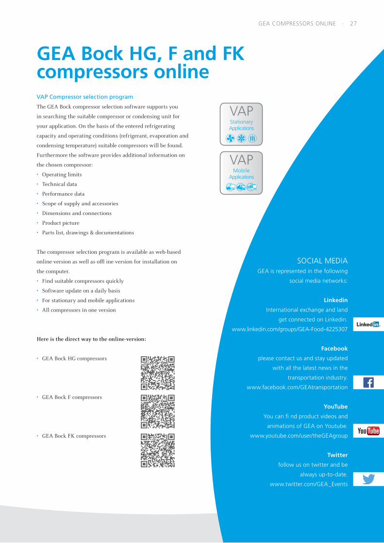
VAP Compressor selection program
The GEA Bock compressor selection software supports you
in searching the suitable compressor or condensing unit for
your application. On the basis of the entered refrigerating
capacity and operating conditions (refrigerant, evaporation and
condensing temperature) suitable compressors will be found.
Furthermore the software provides additional information on
the chosen compressor:
• Operating limits
• Technical data
• Performance data
• Scope of supply and accessories
• Dimensions and connections
• Product picture
• Parts list, drawings & documentations
The compressor selection program is available as web-based
online-version as well as offl ine-version for installation on
the computer.
• Find suitable compressors quickly
• Software update on a daily basis
• For stationary and mobile applications
• All compressors in one version
Here is the direct way to the online-version:
• GEA Bock HG compressors
• GEA Bock F compressors
• GEA Bock FK compressors
SOCIAL MEDIAGEA is represented in the following
social media networks:
International exchange and land
get connected on Linkedin.
www.linkedin.com/groups/GEA-Food-4225307
please contact us and stay updated
with all the latest news in the
transportation industry.
www.facebook.com/GEAtransportation
YouTube
You can fi nd product videos and
animations of GEA on Youtube.
www.youtube.com/user/theGEAgroup
follow us on twitter and be
always up-to-date.
www.twitter.com/GEA_Events
GEA Bock HG, F and FK compressors online
VAPStationaryApplications
VAPMobile
Applications
GEA COMPRESSORS ONLINE · 27
GEA Germany
GEA Bock GmbH
Benzstraße 7
72636 Frickenhausen, Germany
Tel +49 (0)7022 9454-0
Fax +49 (0)7022 9454-137
gea.com 9615
3-07
.201
7
© G
EA B
ock
Gm
bH. A
ll rig
hts
rese
rved
. S
ubje
ct t
o m
odifi
catio
ns. P
rinte
d in
Ger
man
y.
GEA is a global technology company with multi-billion euro sales operations in more than 50 countries.
Founded in 1881 the company is one of the largest providers of innovative equipment and process technology.
GEA is listed in the STOXX® Europe 600 Index.
We live our values.Excellence • Passion • Integrity • Responsibility • GEA-versity