gea searle
TRANSCRIPT

Product range Fresh ideas from Searle
GEA Searle
Engineered efficiency - no matter where or what
2 3
GEA Heat Exchangers - Powered by GEA group
GEA Searle - Making the difference in 2012
2 3
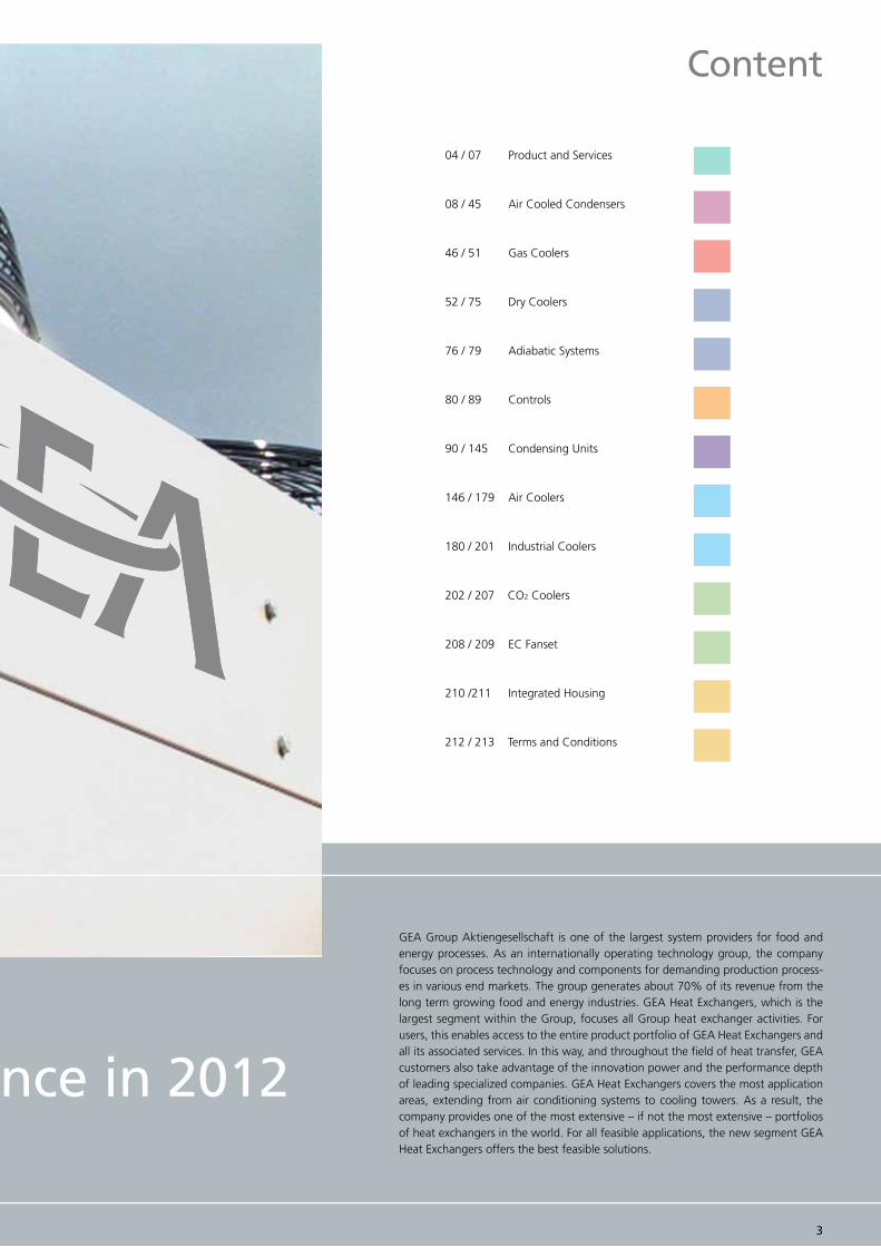
04 / 07 Product and Services
08 / 45 Air Cooled Condensers
46 / 51 Gas Coolers
52 / 75 Dry Coolers
76 / 79 Adiabatic Systems
80 / 89 Controls
90 / 145 Condensing Units
146 / 179 Air Coolers
180 / 201 Industrial Coolers
202 / 207 CO2 Coolers
208 / 209 EC Fanset
210 /211 Integrated Housing
212 / 213 Terms and Conditions
GEA Group Aktiengesellschaft is one of the largest system providers for food and energy processes. As an internationally operating technology group, the company focuses on process technology and components for demanding production process-es in various end markets. The group generates about 70% of its revenue from the long term growing food and energy industries. GEA Heat Exchangers, which is the largest segment within the Group, focuses all Group heat exchanger activities. For users, this enables access to the entire product portfolio of GEA Heat Exchangers and all its associated services. In this way, and throughout the field of heat transfer, GEA customers also take advantage of the innovation power and the performance depth of leading specialized companies. GEA Heat Exchangers covers the most application areas, extending from air conditioning systems to cooling towers. As a result, the company provides one of the most extensive – if not the most extensive – portfolios of heat exchangers in the world. For all feasible applications, the new segment GEA Heat Exchangers offers the best feasible solutions.
GEA Searle - Making the difference in 2012
Content

54
GEA Searle - Products and Services
GEA Searle - Making the difference

54
GEA Searle - Making the difference
Air Coolers
With the increasing importance of energy efficiency, the new GEA Searle coolers utilise fansets which offer significant energy savings over traditional motor assemblies. The KEC & TEC coolers have high efficiency EC fans as standard across the range. All our commercial unit coolers have white powder coated galvanised steel casing (JG and NS are aluminum) and are available in high or low temperature versions, with CO2 and glycol circuiting options. Many of the models in the commercial unit cooler ranges are available ex-stock from your local distributor, with backup stocks held at the UK manu-facturing plant centre.
Air Cooled Condensers
Our range has literally 1000s of models, created through a modular design and variety of fan sizes, offering a greater choice to match your requirements. Our condensers can meet even the most stringent noise restrictions using the latest 6, 8 & 12 pole fansets. In addition, we offer EC technology across the standard range, which offers variable speed control and high efficiency. Due to rising energy costs, efficiency is becoming a key industry issue and is increasingly important on end-user criteria. Our new units use the latest technology to ensure greater energy efficiency. GEA Searle has extensive experience in the design of controls either using the GEA Searle controller or ‘industry standard’ controllers such as Millennium 2 or RDM.
Dry Air Coolers
The range has literally 1000s of models, created through a modular design and variety offan sizes, offering a greater range of solutions to match your requirements. Our Dry Coolers can meet even the most stringent noise restrictions using the latest 6, 8,12 & 16 pole fansets. In addition, we offer EC technology across the standard range, which offers full variable speed control.
Condensing Units
GEA Searle Condensing Units are supplied as standard to a high specification with a complete control package, incorporating: Mains Isolator, Compressor Motor Starter/Overloads or MCB’s for single phase models, Fan speed control & anti-cycle timer, Com-pressor Contactors, Fitted pressure relief valve (PRV), Compressor Crankcase HeatersGEA Searle units range from the NRE with hermetic reciprocating compressors, the NSQ using scroll compressors to the NDQ using the latest digital scroll compressors. There are twin compressor variants of the NSQ and NDQ.
GEA Searle is one of the longest established and principal manufacturers of heat exchange products for the refrigeration and air conditioning industry in Europe. Es-tablished in 1921, GEA Searle boasts a comprehensive range of condensers, coolers and condensing units. GEA Searle products are utilised across many industries. Ap-plications include supermarket cabinets and cold rooms, large scale food freezing plants, food storage and distribution centres, beer cellars, industrial process cooling, combined heat and power installations and air-conditioning equipment for hospitals, offices, schools and museums. In order to guarantee the continued excellence of our products in terms of innovation, design and performance, GEA Searle has invested in one of the most comprehensive Research & Development facilities in the European-refrigeration industry. GEA Searle also undertakes special projects on behalf of other manufacturers, customers and end-users. In our R&D testing facility we are able to test for the following performance characteristics: Duty (kW), Air flow (m3/s), Motor performance, Noise.
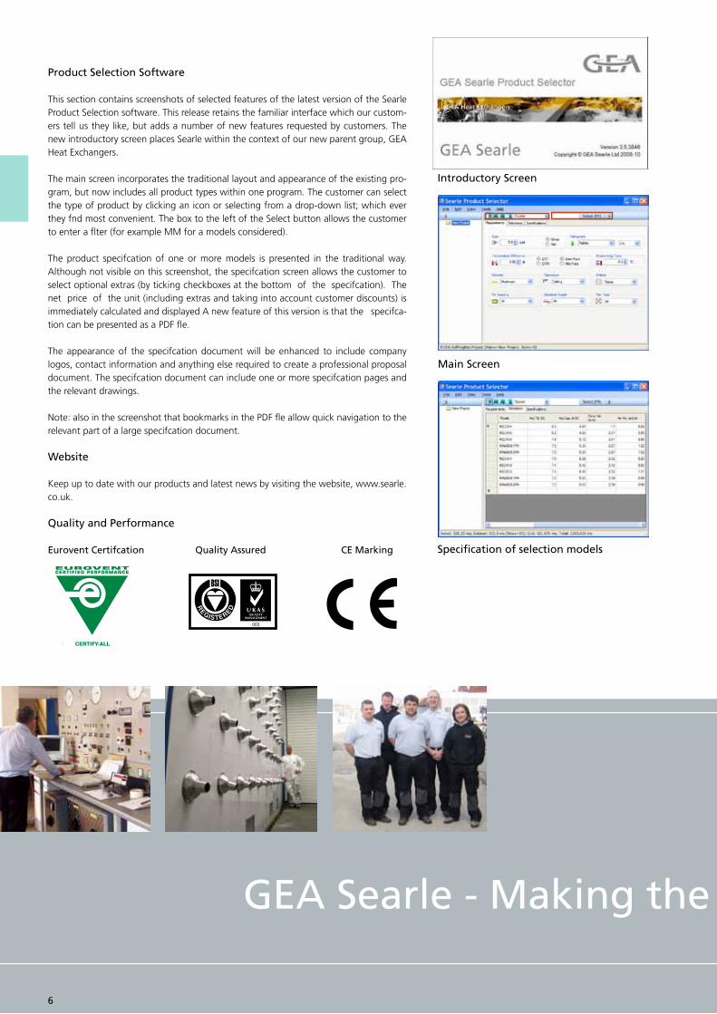
Product Selection Software
This section contains screenshots of selected features of the latest version of the Searle Product Selection software. This release retains the familiar interface which our custom-ers tell us they like, but adds a number of new features requested by customers. The new introductory screen places Searle within the context of our new parent group, GEA Heat Exchangers.
The main screen incorporates the traditional layout and appearance of the existing pro-gram, but now includes all product types within one program. The customer can select the type of product by clicking an icon or selecting from a drop-down list; which ever they fnd most convenient. The box to the left of the Select button allows the customer to enter a flter (for example MM for a models considered).
The product specifcation of one or more models is presented in the traditional way. Although not visible on this screenshot, the specifcation screen allows the customer to select optional extras (by ticking checkboxes at the bottom of the specifcation). The net price of the unit (including extras and taking into account customer discounts) is immediately calculated and displayed A new feature of this version is that the specifca-tion can be presented as a PDF fle.
The appearance of the specifcation document will be enhanced to include company logos, contact information and anything else required to create a professional proposal document. The specifcation document can include one or more specifcation pages and the relevant drawings.
Note: also in the screenshot that bookmarks in the PDF fle allow quick navigation to the relevant part of a large specifcation document.
Website
Keep up to date with our products and latest news by visiting the website, www.searle.co.uk.
Quality and Performance
Eurovent Certifcation Quality Assured CE Marking
Introductory Screen
Main Screen
Specification of selection models
GEA Searle - Making the difference
6

GEA Searle - Products and Services
GEA Searle - Making the difference
76

8
GEA Searle - Air Cooled Condensers
GEA Searle’s new range of condensers means you’ve more choice than ever before, comprising of both flat-bed and V-bank units, arranged in single and double bank configurations, with multiple module lengths. The wide range is suitable for most refrigeration and air conditioning condenser applications. Range benefits: Meet-ing your specification, Assured performance, Designed to be quiet and energy efficient.

98
Control Options
There are various optional GEA Searle control packages available, includ-ing vari-able speed controlled products using Searle inverter control or the latest EC fan control system. The control options include: EC speed control Inverter speed control, Triac speed control, Dual speed step control, Single speed step control. If a speed control method is utilised, Searle recom- mends adding the option of internal motor protection.
Other Options
GEA Searle offers a wide range of accessories and additional options, in-cluding: anti-vibration mounts and leg extensions - to enhance air fow in diffcult loca-tions and Adiabatic cooling System (Please see GEA Searle’s Adiabatic Section for further details or contact your GEA Searle representa-tive).
Vertical Mounting
Units maybe specifed as horizontal (standard) or vertical orientation.Sub-CoolingSub-cooling is achieved by the use of an integrated sub-cooling section which utilises approximately 10% of the coil surface. This pro-vides up to 7K of sub-cooling at the standard rating condition of 15K DT1. Operating below 15K DT1, the amount of sub-cooling is reduced. The total heat of rejection capacity, inclusive of sub-cooling, will be reduced by 5%.
Blygold® Coating
GEA Searle’s specialist coating facility, where a Blygold® coating is applied and cured to protect the fnned coils against harsh environmental condi-tions such as erosion by sand or salt. It provides a barrier and avoids the risk of electrolytic reactions between the two metals involved. The coating contains aluminium, in order to maintain the thermal performance of the coil, resulting in an extension of the lifetime, maximum cooling capacity and reduction of energy costs. The coating is oriented in such a way that it creates a very high chemical resistance at low layer thickness.
Energy Labelling
Energy Labelling is now part of the Eurovent Certify-All scheme. Rating is based on the ratio of nominal duty to power input with banding as in the table below:
Where R= Nominal Capacity Total fan power input
Dewpoint
The capacities shown in this brochure are rated at dew point. This is the pres-sure/temperature condition at which a refrigerant gas begins to condense on the surface. As some refrigerants have signifcant glide (e.g. R407A/ 407C), the saturated gas and saturated liquid temperatures are not necessarily the same. It is important to ensure that all the components of a system are selected using the same rating method whilst the use of mid-point does make selection easier, it is diffcult to measure on site. At the catalogue rating point of 15K DT1, mid point capacities would be approxi-mately 9% higher for R407C than the equivalent dew point fgures shown in the tables.
/
Noise Data
The mean unit sound pressure data at 10m is given for each model in the catalogue and is certifed as part of the Eurovent scheme. Sound power testing and sound pressure calculation are carried out in accor-dance with EN13487. Mean sound pressure levels are for a parallel piped surface surrounding the unit on a refective plane. Power levels and sound spectrum are available on re-quest.
Correction Factors
Multiply the capacity tables by the following factors depending on the DT1 temperature difference:
R507A, R404A
R134a
DT1
8K 20K 17K 15K 12K 10K
0.53 1.33 1.131.00 0.80 0.67
0.49 1.241.050.930.74 0.62
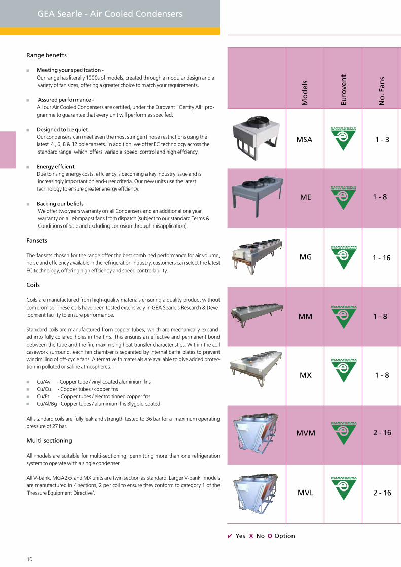
Yes No Option
10 11
GEA Searle - Air Cooled Condensers
Range benefts
Meeting your specifcation - Our range has literally 1000s of models, created through a modular design and a variety of fan sizes, offering a greater choice to match your requirements.
Assured performance - All our Air Cooled Condensers are certifed, under the Eurovent “Certify All” pro- gramme to guarantee that every unit will perform as specifed.
Designed to be quiet - Our condensers can meet even the most stringent noise restrictions using the latest 4 , 6, 8 & 12 pole fansets. In addition, we offer EC technology across the standard range which offers variable speed control and high effciency.
Energy effcient - Due to rising energy costs, effciency is becoming a key industry issue and is increasingly important on end-user criteria. Our new units use the latest technology to ensure greater energy effciency.
Backing our beliefs - We offer two years warranty on all Condensers and an additional one year warranty on all ebmpapst fans from dispatch (subject to our standard Terms & Conditions of Sale and excluding corrosion through misapplication).
Fansets
The fansets chosen for the range offer the best combined performance for air volume, noise and effciency available in the refrigeration industry, customers can select the latest EC technology, offering high effciency and speed controllability.
Coils
Coils are manufactured from high-quality materials ensuring a quality product without compromise. These coils have been tested extensively in GEA Searle’s Research & Deve-lopment facility to ensure performance.
Standard coils are manufactured from copper tubes, which are mechanically expand-ed into fully collared holes in the fins. This ensures an effective and permanent bond between the tube and the fin, maximising heat transfer characteristics. Within the coil casework surround, each fan chamber is separated by internal baffe plates to prevent windmilling of off-cycle fans. Alternative fn materials are available to give added protec-tion in polluted or saline atmospheres: -
Cu/Av - Copper tube / vinyl coated aluminium fns Cu/Cu - Copper tubes / copper fns Cu/Et - Copper tubes / electro tinned copper fns Cu/Al/Bg - Copper tubes / aluminium fns Blygold coated
All standard coils are fully leak and strength tested to 36 bar for a maximum operating pressure of 27 bar.
Multi-sectioning
All models are suitable for multi-sectioning, permitting more than one refrigeration system to operate with a single condenser.
All V-bank, MGA2xx and MX units are twin section as standard. Larger V-bank models are manufactured in 4 sections, 2 per coil to ensure they conform to category 1 of the ‘Pressure Equipment Directive’.
Mod
els
Euro
vent
No.
Fan
s
ME 1 - 8
MSA 1 - 3
MVM 2 - 16
MX 1 - 8
MM 1 - 8
MG 1 - 16
MVL 2 - 16
ME 1 - 8
Mo
del
s
Euro
ven
t
No
. Fan
s
10 11
1 - 8
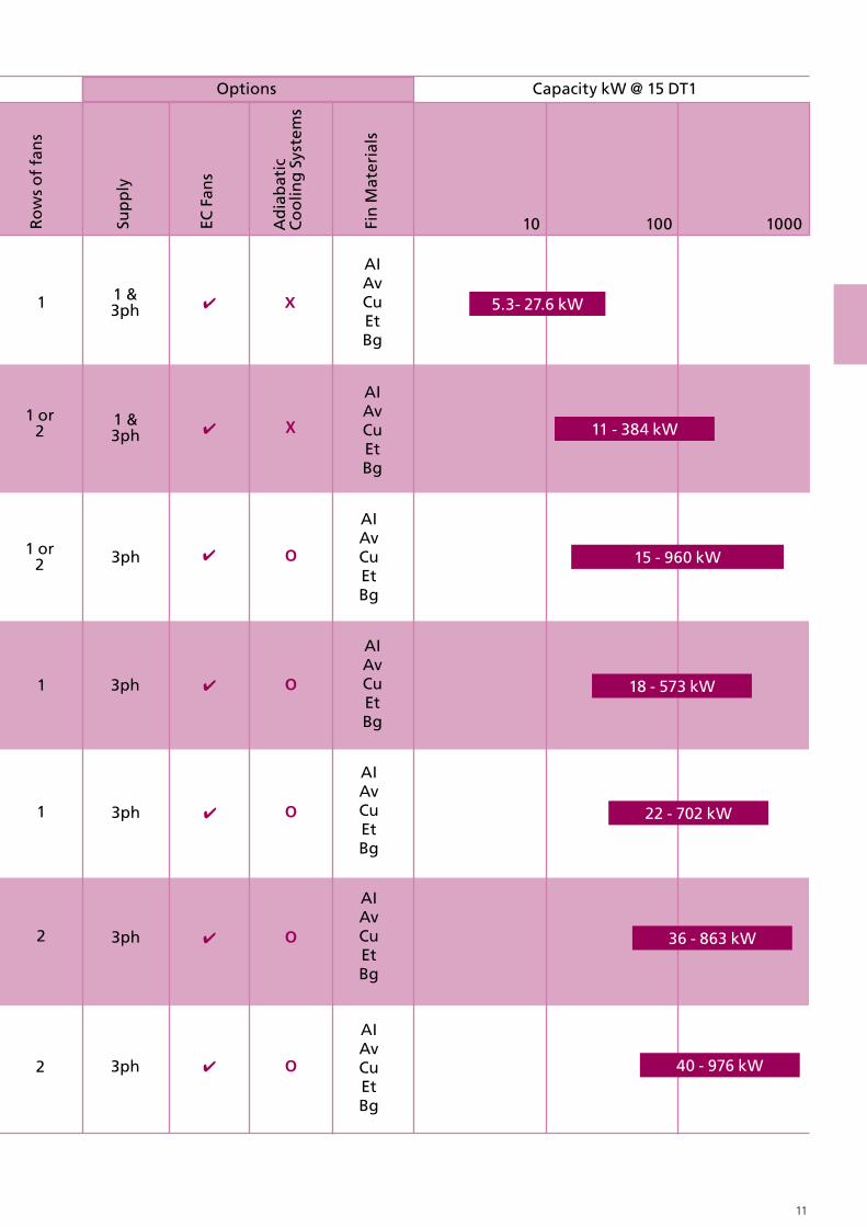
10 100 1000
1 1 &3ph
AIAvCuEtBg
5.3- 27.6 kW
2 3ph 36 - 863 kW
AIAvCuEtBg
1 3ph 22 - 702 kW
AIAvCuEtBg
1 3ph 18 - 573 kW
AIAvCuEtBg
3ph1 or2 15 - 960 kW
AIAvCuEtBg
1 &3ph 11 - 384 kW
1 or2
AIAvCuEtBg
2 3ph 40 - 976 kW
AIAvCuEtBg
Ro
ws
of
fan
s
Sup
ply
EC F
ans
Fin
Mat
eria
ls
Capacity kW @ 15 DT1Options
Ad
iab
atic
C
oo
ling
Sys
tem
s

GEA Searle - MS Air Cooled Condensers
12 13
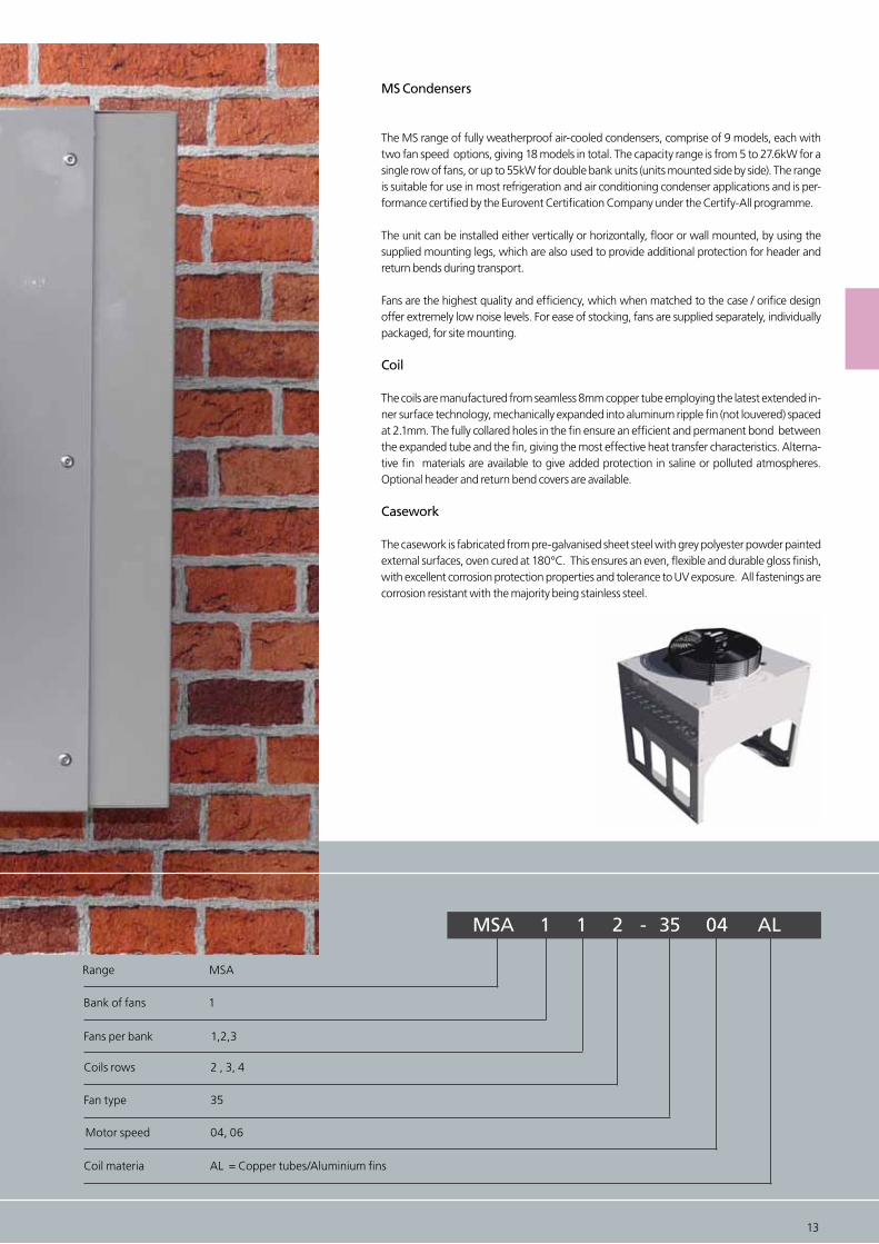
MS Condensers
The MS range of fully weatherproof air-cooled condensers, comprise of 9 models, each with two fan speed options, giving 18 models in total. The capacity range is from 5 to 27.6kW for a single row of fans, or up to 55kW for double bank units (units mounted side by side). The range is suitable for use in most refrigeration and air conditioning condenser applications and is per-formance certified by the Eurovent Certification Company under the Certify-All programme.
The unit can be installed either vertically or horizontally, floor or wall mounted, by using the supplied mounting legs, which are also used to provide additional protection for header and return bends during transport.
Fans are the highest quality and efficiency, which when matched to the case / orifice design offer extremely low noise levels. For ease of stocking, fans are supplied separately, individually packaged, for site mounting.
Coil
The coils are manufactured from seamless 8mm copper tube employing the latest extended in-ner surface technology, mechanically expanded into aluminum ripple fin (not louvered) spaced at 2.1mm. The fully collared holes in the fin ensure an efficient and permanent bond between the expanded tube and the fin, giving the most effective heat transfer characteristics. Alterna-tive fin materials are available to give added protection in saline or polluted atmospheres. Optional header and return bend covers are available.
Casework
The casework is fabricated from pre-galvanised sheet steel with grey polyester powder painted external surfaces, oven cured at 180°C. This ensures an even, flexible and durable gloss finish, with excellent corrosion protection properties and tolerance to UV exposure. All fastenings are corrosion resistant with the majority being stainless steel.
MSA 1 1 2 - 35 04 AL
Range MSA
Fans per bank 1,2,3
Coils rows 2 , 3, 4
Motor speed 04, 06
Coil materia AL = Copper tubes/Aluminium fins
Bank of fans 1
Fan type 35
12 13
14 15
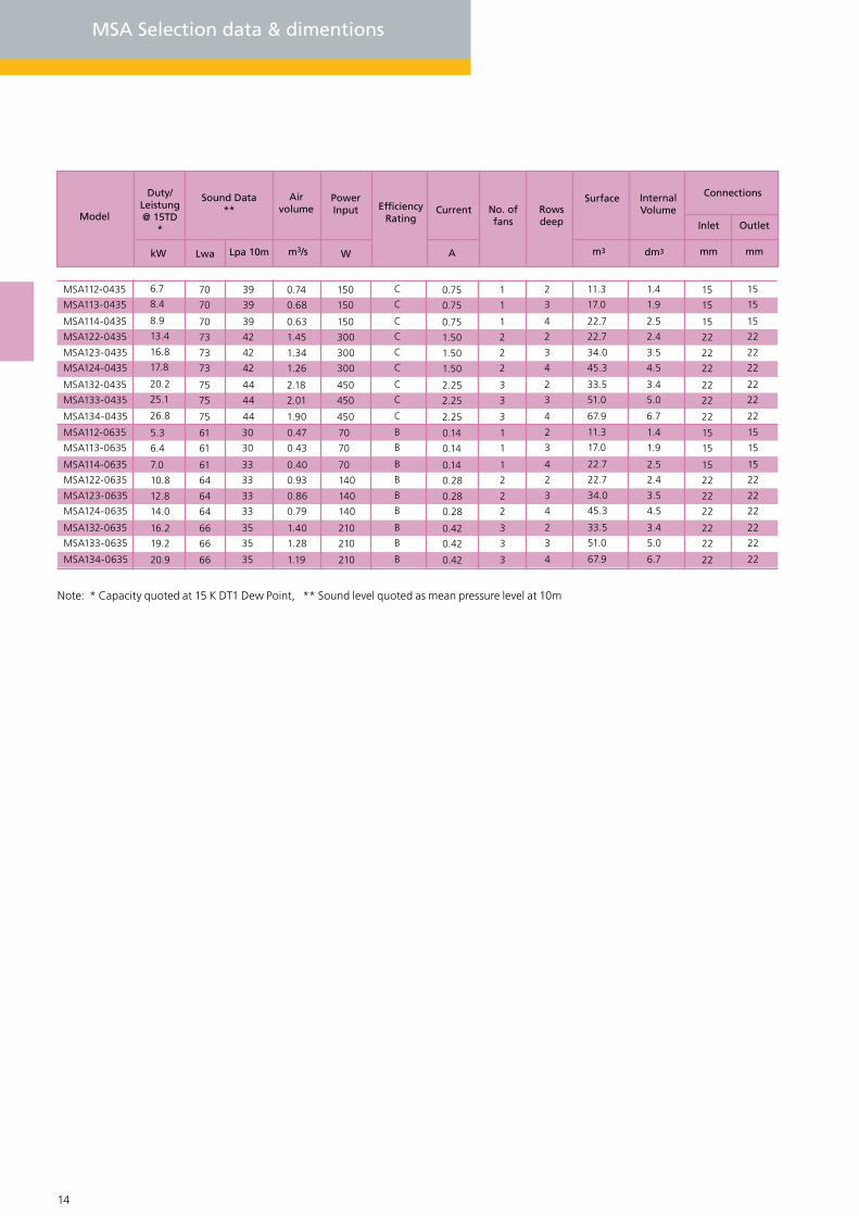
MSA Selection data & dimentions
39
39
39
42
42
42
44
44
44
70
70
70
73
73
73
75
75
75
Lwa Lpa 10m
Inlet
mmkW
6.7
8.4
8.9
13.4
16.8
17.8
20.2
25.1
26.8
W
15
15
15
22
22
22
22
22
22
Outlet
mm
30
30
33
33
33
33
35
35
35
MSA112-0435
MSA113-0435
MSA114-0435
MSA122-0435
MSA123-0435
MSA124-0435
MSA132-0435
MSA133-0435
MSA134-0435
MSA112-0635
MSA113-0635
MSA114-0635
MSA122-0635
MSA123-0635
MSA124-0635
MSA132-0635
MSA133-0635
MSA134-0635
C
C
C
C
C
C
C
C
C
B
B
B
B
B
B
B
B
B
15
15
15
22
22
22
22
22
22
15
15
15
22
22
22
22
22
22
A
0.75
0.75
0.75
1.50
1.50
1.50
2.25
2.25
2.25
0.14
0.14
0.14
0.28
0.28
0.28
0.42
0.42
0.42
61
61
61
64
64
64
66
66
66
11.3
17.0
22.7
22.7
34.0
45.3
33.5
51.0
67.9
m3
11.3
17.0
22.7
22.7
34.0
45.3
33.5
51.0
67.9
0.74
0.68
0.63
1.45
1.34
1.26
2.18
2.01
1.90
m3/s
0.47
0.43
0.40
0.93
0.86
0.79
1.40
1.28
1.19
1
1
1
2
2
2
3
3
3
1
1
1
2
2
2
3
3
3
2
3
4
2
3
4
2
3
4
2
3
4
2
3
4
2
3
4
5.3
6.4
7.0
10.8
12.8
14.0
16.2
19.2
20.9
150
150
150
300
300
300
450
450
450
70
70
70
140
140
140
210
210
210
15
15
15
22
22
22
22
22
22
Note: * Capacity quoted at 15 K DT1 Dew Point, ** Sound level quoted as mean pressure level at 10m
1.4
1.9
2.5
2.4
3.5
4.5
3.4
5.0
6.7
1.4
1.9
2.5
2.4
3.5
4.5
3.4
5.0
6.7
dm3
Model
Duty/ Leistung @ 15TD
*
Internal VolumeRows
deep
Air volume
Power Input CurrentEfficiency
RatingNo. of fans
Sound Data**
Surface Connections

14 15
666.
5
304.
723
3.5
Wall mounted footprintWall mounted operation
225
(32.0)
225
12
1 offset MTG hole(wall mounted only)
225
225
A
530.
3
304.7
A
All units supplied less fans
Horizontal operation & Packed
35
62.5 62.5
1751.2 O/A
1845 Over optional cover
MS 132, 133, 134
538.
2530.31720.0 Casework
Vertical Floor MTG
565.
3
530.
335 304.735
Opt
iona
l hea
der
cove
r (b
oth
ends
)
62.5 62.5
620 Casework
745 Over optional cover
C
62.5 62.5
1170 Casework
1295 Over optional cover
MS 112, 113, 114
644.2 O/A 1201.2 O/A
MS 122,1 23, 124
C
B B
A
Horizontal floor mounted operation footprint
450
A
Horizontal floor mounted operation footprint
12
450 450B
265
5701 15MSA 112
MSA 113
MSA 114
2
3
20
22
24
34
38
41
48
53
58
4
2
3
4
2
3
4
MSA 122
MSA 123
MSA 124
MSA 132
MSA 133
MSA 134
17
19
24
28
32
33
38
44
1
1
2
2
2
3
3
3
570
570
1120
1120
N/A
N/A
N/A
100
100
100
1550
1550
1550
1120
1670
1670
1670
Model Dim ACoil rows
Weight(Less fan)Fans
Weight(Inc fan)Dim B
kg kgmmmm
12

16 17
GEA Searle - ME Air Cooled Condensers
HyBlade®
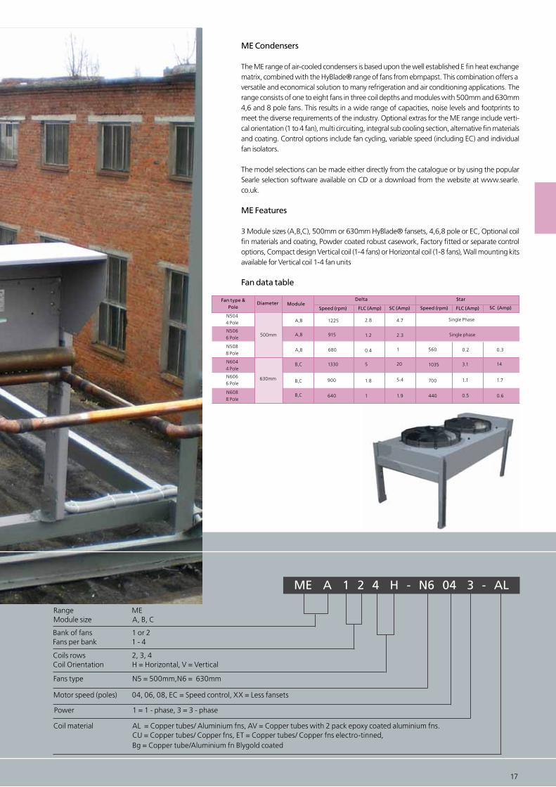
ME Condensers
The ME range of air-cooled condensers is based upon the well established E fin heat exchangematrix, combined with the HyBlade® range of fans from ebmpapst. This combination offers aversatile and economical solution to many refrigeration and air conditioning applications. The range consists of one to eight fans in three coil depths and modules with 500mm and 630mm 4,6 and 8 pole fans. This results in a wide range of capacities, noise levels and footprints to meet the diverse requirements of the industry. Optional extras for the ME range include verti-cal orientation (1 to 4 fan), multi circuiting, integral sub cooling section, alternative fin materials and coating. Control options include fan cycling, variable speed (including EC) and individual fan isolators.
The model selections can be made either directly from the catalogue or by using the popular Searle selection software available on CD or a download from the website at www.searle.co.uk.
ME Features
3 Module sizes (A,B,C), 500mm or 630mm HyBlade® fansets, 4,6,8 pole or EC, Optional coil fin materials and coating, Powder coated robust casework, Factory fitted or separate control options, Compact design Vertical coil (1-4 fans) or Horizontal coil (1-8 fans), Wall mounting kitsavailable for Vertical coil 1-4 fan units
Fan data table
ME A 1 2 4 H - N6 04 3 - AL
Range MEModule size A, B, C
Fans type N5 = 500mm,N6 = 630mm
Power 1 = 1 - phase, 3 = 3 - phase
Coil material AL = Copper tubes/ Aluminium fns, AV = Copper tubes with 2 pack epoxy coated aluminium fns. CU = Copper tubes/ Copper fns, ET = Copper tubes/ Copper fns electro-tinned, Bg = Copper tube/Aluminium fn Blygold coated
Motor speed (poles) 04, 06, 08, EC = Speed control, XX = Less fansets
16 17
A,B
B,C 5 1035 3.1 14
900 1.8 700 1.1 1.7
1 1.9 440 0.5 0.6
0.4 560 0.2 0.3
A,B 2.8
A,B 1.2
1330
680
1225
915
20
5.4
1
4.7
2.3
B,C
B,C
500mm
630mm
640
N5066 Pole
N6044 Pole
N6066 Pole
N6088 Pole
N5044 Pole
N5088 Pole
Fan type &Pole
Diameter ModuleSpeed (rpm)
Delta
FLC (Amp) SC (Amp)
Star
Single Phase
Speed (rpm) FLC (Amp) SC (Amp)
Single phase
Bank of fans 1 or 2Fans per bank 1 - 4
Coils rows 2, 3, 4Coil Orientation H = Horizontal, V = Vertical
18 19
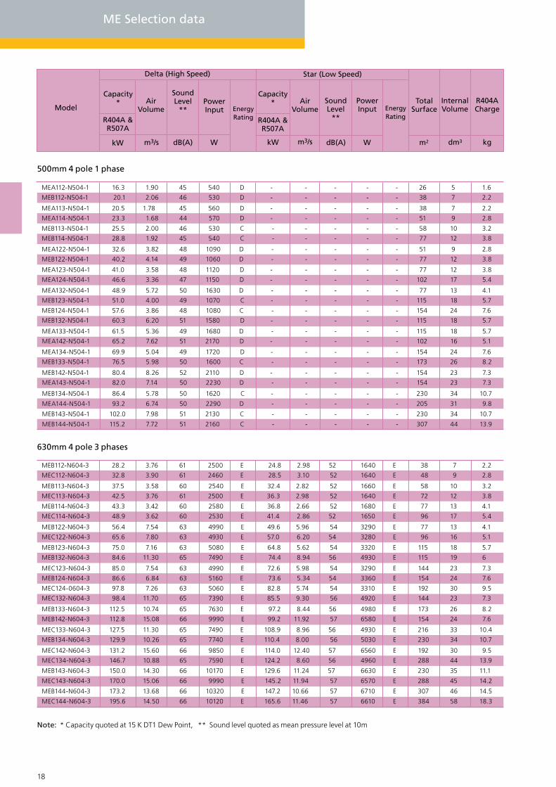
ME Selection data
MEB112-N604-3 28.2 3.76 61 2500 E 24.8 2.98 52 1640 E 38 7 2.2
MEC112-N604-3 32.8 3.90 61 2460 E 28.5 3.10 52 1640 E 48 9 2.8
MEB113-N604-3 37.5 3.58 60 2540 E 32.4 2.82 52 1660 E 58 10 3.2
MEC113-N604-3 42.5 3.76 61 2500 E 36.3 2.98 52 1640 E 72 12 3.8
MEB114-N604-3 43.3 3.42 60 2580 E 36.8 2.66 52 1680 E 77 13 4.1
MEC114-N604-3 48.9 3.62 60 2530 E 41.4 2.86 52 1650 E 96 17 5.4
MEB122-N604-3 56.4 7.54 63 4990 E 49.6 5.96 54 3290 E 77 13 4.1
MEC122-N604-3 65.6 7.80 63 4930 E 57.0 6.20 54 3280 E 96 16 5.1
MEB123-N604-3 75.0 7.16 63 5080 E 64.8 5.62 54 3320 E 115 18 5.7
MEB132-N604-3 84.6 11.30 65 7490 E 74.4 8.94 56 4930 E 115 19 6
MEC123-N604-3 85.0 7.54 63 4990 E 72.6 5.98 54 3290 E 144 23 7.3
MEB124-N604-3 86.6 6.84 63 5160 E 73.6 5.34 54 3360 E 154 24 7.6
MEC124-0604-3 97.8 7.26 63 5060 E 82.8 5.74 54 3310 E 192 30 9.5
MEC132-N604-3 98.4 11.70 65 7390 E 85.5 9.30 56 4920 E 144 23 7.3
MEB133-N604-3 112.5 10.74 65 7630 E 97.2 8.44 56 4980 E 173 26 8.2
MEB142-N604-3 112.8 15.08 66 9990 E 99.2 11.92 57 6580 E 154 24 7.6
MEC133-N604-3 127.5 11.30 65 7490 E 108.9 8.96 56 4930 E 216 33 10.4
MEB134-N604-3 129.9 10.26 65 7740 E 110.4 8.00 56 5030 E 230 34 10.7
MEC142-N604-3 131.2 15.60 66 9850 E 114.0 12.40 57 6560 E 192 30 9.5
MEC134-N604-3 146.7 10.88 65 7590 E 124.2 8.60 56 4960 E 288 44 13.9
MEB143-N604-3 150.0 14.30 66 10170 E 129.6 11.24 57 6630 E 230 35 11.1
MEC143-N604-3 170.0 15.06 66 9990 E 145.2 11.94 57 6570 E 288 45 14.2
MEB144-N604-3 173.2 13.68 66 10320 E 147.2 10.66 57 6710 E 307 46 14.5
MEC144-N604-3 195.6 14.50 66 10120 E 165.6 11.46 57 6610 E 384 58 18.3
500mm 4 pole 1 phase
630mm 4 pole 3 phases
Note: * Capacity quoted at 15 K DT1 Dew Point, ** Sound level quoted as mean pressure level at 10m
Model
Capacity*
R404A &R507A
kW m3/s dB(A) W kW m3/s dB(A) W m2 dm3 kg
AirVolume
SoundLevel
**PowerInput Energy
Rating
Delta (High Speed) Star (Low Speed)
R404A &R507A
AirVolume
PowerInput Energy
Rating
TotalSurface
InternalVolume
R404ACharge
Capacity* Sound
Level**
MEA112-N504-1 16.3 1.90 45 540 D - - - - - 26 5 1.6
MEB112-N504-1 20.1 2.06 46 530 D - - - - - 38 7 2.2
MEA113-N504-1 20.5 1.78 45 560 D - - - - - 38 7 2.2
MEA114-N504-1 23.3 1.68 44 570 D - - - - - 51 9 2.8
MEB113-N504-1 25.5 2.00 46 530 C - - - - - 58 10 3.2
MEB114-N504-1 28.8 1.92 45 540 C - - - - - 77 12 3.8
MEA122-N504-1 32.6 3.82 48 1090 D - - - - - 51 9 2.8
MEB122-N504-1 40.2 4.14 49 1060 D - - - - - 77 12 3.8
MEA123-N504-1 41.0 3.58 48 1120 D - - - - - 77 12 3.8
MEA124-N504-1 46.6 3.36 47 1150 D - - - - - 102 17 5.4
MEA132-N504-1 48.9 5.72 50 1630 D - - - - - 77 13 4.1
MEB123-N504-1 51.0 4.00 49 1070 C - - - - - 115 18 5.7
MEB124-N504-1 57.6 3.86 48 1080 C - - - - - 154 24 7.6
MEB132-N504-1 60.3 6.20 51 1580 D - - - - - 115 18 5.7
MEA133-N504-1 61.5 5.36 49 1680 D - - - - - 115 18 5.7
MEA142-N504-1 65.2 7.62 51 2170 D - - - - - 102 16 5.1
MEA134-N504-1 69.9 5.04 49 1720 D - - - - - 154 24 7.6
MEB133-N504-1 76.5 5.98 50 1600 C - - - - - 173 26 8.2
MEB142-N504-1 80.4 8.26 52 2110 D - - - - - 154 23 7.3
MEA143-N504-1 82.0 7.14 50 2230 D - - - - - 154 23 7.3
MEB134-N504-1 86.4 5.78 50 1620 C - - - - - 230 34 10.7
MEA144-N504-1 93.2 6.74 50 2290 D - - - - - 205 31 9.8
MEB143-N504-1 102.0 7.98 51 2130 C - - - - - 230 34 10.7
MEB144-N504-1 115.2 7.72 51 2160 C - - - - - 307 44 13.9
18 19
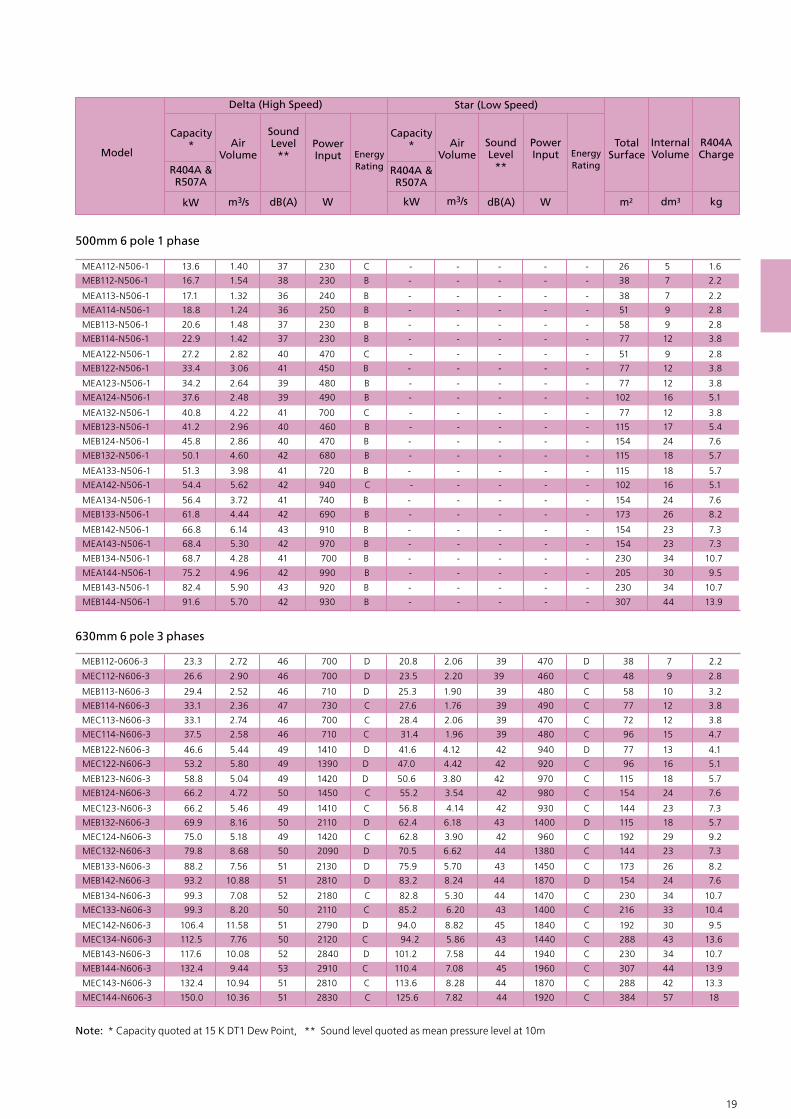
MEB112-0606-3 23.3 2.72 46 700 D 20.8 2.06 39 470 D 38 7 2.2
MEC112-N606-3 26.6 2.90 46 700 D 23.5 2.20 39 460 C 48 9 2.8
MEB113-N606-3 29.4 2.52 46 710 D 25.3 1.90 39 480 C 58 10 3.2
MEB114-N606-3 33.1 2.36 47 730 C 27.6 1.76 39 490 C 77 12 3.8
MEC113-N606-3 33.1 2.74 46 700 C 28.4 2.06 39 470 C 72 12 3.8
MEC114-N606-3 37.5 2.58 46 710 C 31.4 1.96 39 480 C 96 15 4.7
MEB122-N606-3 46.6 5.44 49 1410 D 41.6 4.12 42 940 D 77 13 4.1
MEC122-N606-3 53.2 5.80 49 1390 D 47.0 4.42 42 920 C 96 16 5.1
MEB123-N606-3 58.8 5.04 49 1420 D 50.6 3.80 42 970 C 115 18 5.7
MEB124-N606-3 66.2 4.72 50 1450 C 55.2 3.54 42 980 C 154 24 7.6
MEC123-N606-3 66.2 5.46 49 1410 C 56.8 4.14 42 930 C 144 23 7.3
MEB132-N606-3 69.9 8.16 50 2110 D 62.4 6.18 43 1400 D 115 18 5.7
MEC124-N606-3 75.0 5.18 49 1420 C 62.8 3.90 42 960 C 192 29 9.2
MEC132-N606-3 79.8 8.68 50 2090 D 70.5 6.62 44 1380 C 144 23 7.3
MEB133-N606-3 88.2 7.56 51 2130 D 75.9 5.70 43 1450 C 173 26 8.2
MEB142-N606-3 93.2 10.88 51 2810 D 83.2 8.24 44 1870 D 154 24 7.6
MEB134-N606-3 99.3 7.08 52 2180 C 82.8 5.30 44 1470 C 230 34 10.7
MEC133-N606-3 99.3 8.20 50 2110 C 85.2 6.20 43 1400 C 216 33 10.4
MEC142-N606-3 106.4 11.58 51 2790 D 94.0 8.82 45 1840 C 192 30 9.5
MEC134-N606-3 112.5 7.76 50 2120 C 94.2 5.86 43 1440 C 288 43 13.6
MEB143-N606-3 117.6 10.08 52 2840 D 101.2 7.58 44 1940 C 230 34 10.7
MEB144-N606-3 132.4 9.44 53 2910 C 110.4 7.08 45 1960 C 307 44 13.9
MEC143-N606-3 132.4 10.94 51 2810 C 113.6 8.28 44 1870 C 288 42 13.3
MEC144-N606-3 150.0 10.36 51 2830 C 125.6 7.82 44 1920 C 384 57 18
500mm 6 pole 1 phase
630mm 6 pole 3 phases
MEA112-N506-1 13.6 1.40 37 230 C - - - - - 26 5 1.6
MEB112-N506-1 16.7 1.54 38 230 B - - - - - 38 7 2.2
MEA113-N506-1 17.1 1.32 36 240 B - - - - - 38 7 2.2
MEA114-N506-1 18.8 1.24 36 250 B - - - - - 51 9 2.8
MEB113-N506-1 20.6 1.48 37 230 B - - - - - 58 9 2.8
MEB114-N506-1 22.9 1.42 37 230 B - - - - - 77 12 3.8
MEA122-N506-1 27.2 2.82 40 470 C - - - - - 51 9 2.8
MEB122-N506-1 33.4 3.06 41 450 B - - - - - 77 12 3.8
MEA123-N506-1 34.2 2.64 39 480 B - - - - - 77 12 3.8
MEA124-N506-1 37.6 2.48 39 490 B - - - - - 102 16 5.1
MEA132-N506-1 40.8 4.22 41 700 C - - - - - 77 12 3.8
MEB123-N506-1 41.2 2.96 40 460 B - - - - - 115 17 5.4
MEB124-N506-1 45.8 2.86 40 470 B - - - - - 154 24 7.6
MEB132-N506-1 50.1 4.60 42 680 B - - - - - 115 18 5.7
MEA133-N506-1 51.3 3.98 41 720 B - - - - - 115 18 5.7
MEA142-N506-1 54.4 5.62 42 940 C - - - - - 102 16 5.1
MEA134-N506-1 56.4 3.72 41 740 B - - - - - 154 24 7.6
MEB133-N506-1 61.8 4.44 42 690 B - - - - - 173 26 8.2
MEB142-N506-1 66.8 6.14 43 910 B - - - - - 154 23 7.3
MEA143-N506-1 68.4 5.30 42 970 B - - - - - 154 23 7.3
MEB134-N506-1 68.7 4.28 41 700 B - - - - - 230 34 10.7
MEA144-N506-1 75.2 4.96 42 990 B - - - - - 205 30 9.5
MEB143-N506-1 82.4 5.90 43 920 B - - - - - 230 34 10.7
MEB144-N506-1 91.6 5.70 42 930 B - - - - - 307 44 13.9
Note: * Capacity quoted at 15 K DT1 Dew Point, ** Sound level quoted as mean pressure level at 10m
Model
Capacity*
R404A &R507A
kW m3/s dB(A) W kW m3/s dB(A) W m2 dm3 kg
AirVolume
SoundLevel
**PowerInput Energy
Rating
Delta (High Speed) Star (Low Speed)
R404A &R507A
AirVolume
PowerInput Energy
Rating
TotalSurface
InternalVolume
R404ACharge
Capacity* Sound
Level**
20 21
ME Selection data
Model
Capacity*
R404A &R507A
kW m3/s dB(A) W kW m3/s dB(A) W m2 dm3 kg
AirVolume
SoundLevel
**PowerInput Energy
Rating
Delta (High Speed) Star (Low Speed)
R404A &R507A
AirVolume
PowerInput Energy
Rating
TotalSurface
InternalVolume
R404ACharge
Capacity* Sound
Level**
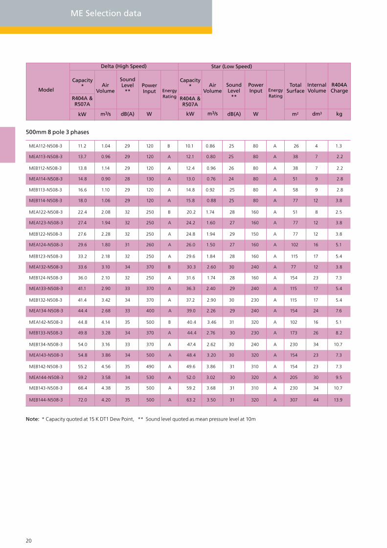
500mm 8 pole 3 phases
MEA112-N508-3 11.2 1.04 29 120 B 10.1 0.86 25 80 A 26 4 1.3
MEA113-N508-3 13.7 0.96 29 120 A 12.1 0.80 25 80 A 38 7 2.2
MEB112-N508-3 13.8 1.14 29 120 A 12.4 0.96 26 80 A 38 7 2.2
MEA114-N508-3 14.8 0.90 28 130 A 13.0 0.76 24 80 A 51 9 2.8
MEB113-N508-3 16.6 1.10 29 120 A 14.8 0.92 25 80 A 58 9 2.8
MEB114-N508-3 18.0 1.06 29 120 A 15.8 0.88 25 80 A 77 12 3.8
MEA122-N508-3 22.4 2.08 32 250 B 20.2 1.74 28 160 A 51 8 2.5
MEA123-N508-3 27.4 1.94 32 250 A 24.2 1.60 27 160 A 77 12 3.8
MEB122-N508-3 27.6 2.28 32 250 A 24.8 1.94 29 150 A 77 12 3.8
MEA124-N508-3 29.6 1.80 31 260 A 26.0 1.50 27 160 A 102 16 5.1
MEB123-N508-3 33.2 2.18 32 250 A 29.6 1.84 28 160 A 115 17 5.4
MEA132-N508-3 33.6 3.10 34 370 B 30.3 2.60 30 240 A 77 12 3.8
MEB124-N508-3 36.0 2.10 32 250 A 31.6 1.74 28 160 A 154 23 7.3
MEA133-N508-3 41.1 2.90 33 370 A 36.3 2.40 29 240 A 115 17 5.4
MEB132-N508-3 41.4 3.42 34 370 A 37.2 2.90 30 230 A 115 17 5.4
MEA134-N508-3 44.4 2.68 33 400 A 39.0 2.26 29 240 A 154 24 7.6
MEA142-N508-3 44.8 4.14 35 500 B 40.4 3.46 31 320 A 102 16 5.1
MEB133-N508-3 49.8 3.28 34 370 A 44.4 2.76 30 230 A 173 26 8.2
MEB134-N508-3 54.0 3.16 33 370 A 47.4 2.62 30 240 A 230 34 10.7
MEA143-N508-3 54.8 3.86 34 500 A 48.4 3.20 30 320 A 154 23 7.3
MEB142-N508-3 55.2 4.56 35 490 A 49.6 3.86 31 310 A 154 23 7.3
MEA144-N508-3 59.2 3.58 34 530 A 52.0 3.02 30 320 A 205 30 9.5
MEB143-N508-3 66.4 4.38 35 500 A 59.2 3.68 31 310 A 230 34 10.7
MEB144-N508-3 72.0 4.20 35 500 A 63.2 3.50 31 320 A 307 44 13.9
Note: * Capacity quoted at 15 K DT1 Dew Point, ** Sound level quoted as mean pressure level at 10m
20 21
Model
Capacity*
R404A &R507A
kW m3/s dB(A) W kW m3/s dB(A) W m2 dm3 kg
AirVolume
SoundLevel
**PowerInput Energy
Rating
Delta (High Speed) Star (Low Speed)
R404A &R507A
AirVolume
PowerInput Energy
Rating
TotalSurface
InternalVolume
R404ACharge
Capacity* Sound
Level**
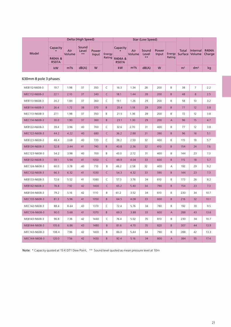
630mm 8 pole 3 phases
MEB112-N608-3 19.7 1.98 37 350 C 16.3 1.34 28 200 B 38 7 2.2
MEC112-N608-3 22.1 2.10 37 340 C 18.1 1.44 28 200 B 48 8 2.5
MEB113-N608-3 24.2 1.84 37 360 C 19.1 1.26 29 200 B 58 10 3.2
MEB114-N608-3 26.4 1.72 38 370 B 20.4 1.18 29 200 B 77 12 3.8
MEC113-N608-3 27.1 1.98 37 350 B 21.5 1.36 28 200 B 72 12 3.8
MEC114-N608-3 30.0 1.90 37 360 B 23.1 1.30 29 200 A 96 15 4.7
MEB122-N608-3 39.4 3.96 40 700 C 32.6 2.70 31 400 B 77 12 3.8
MEC122-N608-3 44.2 4.22 40 680 C 36.2 2.88 31 390 B 96 16 5.1
MEB123-N608-3 48.4 3.68 40 720 C 38.2 2.50 32 400 B 115 18 5.7
MEB124-N608-3 52.8 3.44 41 740 B 40.8 2.36 32 410 B 154 24 7.6
MEC123-N608-3 54.2 3.98 40 700 B 43.0 2.72 31 400 B 144 23 7.3
MEB132-N608-3 59.1 5.94 41 1050 C 48.9 4.04 33 600 B 115 18 5.7
MEC124-N608-3 60.0 3.78 40 710 B 46.2 2.58 32 400 A 192 29 9.2
MEC132-N608-3 66.3 6.32 41 1030 C 54.3 4.32 33 590 B 144 23 7.3
MEB133-N608-3 72.6 5.52 41 1080 C 57.3 3.76 34 610 B 173 26 8.2
MEB142-N608-3 78.8 7.92 42 1400 C 65.2 5.40 34 790 B 154 23 7.3
MEB134-N608-3 79.2 5.16 42 1110 B 61.2 3.52 34 610 B 230 34 10.7
MEC133-N608-3 81.3 5.96 41 1050 B 64.5 4.08 33 600 B 216 32 10.1
MEC142-N608-3 88.4 8.44 43 1370 C 72.4 5.76 34 780 B 192 30 9.5
MEC134-N608-3 90.0 5.68 41 1070 B 69.3 3.88 33 600 A 288 43 13.6
MEB143-N608-3 96.8 7.36 42 1440 C 76.4 5.02 35 810 B 230 34 10.7
MEB144-N608-3 105.6 6.86 43 1480 B 81.6 4.70 35 820 B 307 44 13.9
MEC143-N608-3 108.4 7.96 42 1400 B 86.0 5.44 34 790 B 288 42 13.3
MEC144-N608-3 120.0 7.56 42 1430 B 92.4 5.16 34 800 A 384 55 17.4
Note: * Capacity quoted at 15 K DT1 Dew Point, ** Sound level quoted as mean pressure level at 10m

22 23
ME Model drawings & Dimensions
ME Single bank horizontal unit ME Vertical unit
Optional fan isolator
W (Overall legs)
Optional J/box
D Fixing Centres
772 Fixing centres
H (o
vera
ll ca
sew
ork)
ME Double bank horizontal unit
Optional fan isolator
W (Overall legs)
Optional J/box
D Fixing Centres
1fixing hole 11.0mm x 16.5mmin base of each leg
15
800 42.9
1070
363
288
241
515
A
C
B1 B2
38

22 23
MEA112 79589311 867 898 863 75 85 1.3/8” 7/8”MEA113 79589311 867 898 863 80 97 1.1/8” 7/8”MEA114 79589311 867 898 863 85 107 1.3/8” 7/8”MEA122 1600169821 867 898 863 120 142 1.3/8” 7/8”MEA123 1600169821 867 898 863 130 163 1.3/8” 7/8”MEA124 1600169831 867 898 863 140 184 1.3/8” 7/8”MEA132 2403250131 867 898 863 164 197 1.3/8” 7/8”MEA133 2403250131 867 898 863 183 233 1.5/8” 1.1/8”MEA134 2403250131 867 898 863 195 261 2.1/8” 1.3/8”MEA142 3210330841 867 898 863 209 254 1.5/8” 1.1/8”MEA143 3210330841 867 898 863 229 296 2.1/8” 1.1/8”MEA144 3210330841 867 898 863 249 338 2.1/8” 1.3/8”MEA212 79589312 1695 1726 - 144 164 1.3/8” 7/8”MEA213 79589312 1695 1726 - 154 187 1.1/8” 7/8”MEA214 79589312 1695 1726 - 164 209 1.3/8” 7/8”MEA222 1600169822 1695 1726 - 233 278 1.3/8” 7/8”MEA223 1600169822 1695 1726 - 253 320 1.3/8” 7/8”MEA224 1600169822 1695 1726 - 273 362 1.3/8” 7/8”MEA232 2403250132 1695 1726 - 322 389 1.3/8” 7/8”MEA233 2403250132 1695 1726 - 360 460 1.5/8” 1.1/8”MEA234 2403250132 1695 1726 - 383 517 2.1/8” 1.3/8”MEA242 3210330842 1695 1726 - 413 502 1.5/8” 1.1/8”MEA243 3210330842 1695 1726 - 452 586 2.1/8” 1.1/8”MEA244 3210330842 1695 1726 - 492 670 2.1/8” 1.3/8”MEB112 1195129311 867 898 863 97 113 1.3/8” 7/8”MEB113 1195129311 867 898 863 104 129 1.3/8” 7/8”MEB114 1195129311 867 898 863 113 146 1.3/8” 7/8”MEB122 2403250121 867 898 863 163 196 1.3/8” 7/8”MEB123 2403250121 867 898 863 177 227 1.5/8” 7/8”MEB124 2403250131 867 898 863 192 259 2.1/8” 1.3/8”MEB132 3605370331 867 898 863 230 280 1.5/8” 1.1/8”MEB133 3605370331 867 898 863 252 327 2.1/8” 1.1/8”MEB134 3605370331 867 898 863 274 375 2.1/8” 1.3/8”
MEB212 1195129312 1695 1726 - 188 221 1.3/8” 7/8”MEB213 1195129312 1695 1726 - 203 252 1.1/8” 7/8”MEB214 1195129312 1695 1726 - 219 286 1.3/8” 7/8”MEB222 2403250122 1695 1726 - 319 386 1.3/8” 7/8”MEB223 2403250122 1695 1726 - 349 449 1.5/8” 1.1/8”MEB224 2403250122 1695 1726 - 379 512 2.1/8” 1.3/8”MEB232 3605370332 1695 1726 - 454 554 1.5/8” 1.1/8”MEB233 3605370332 1695 1726 - 498 648 2.1/8” 1.1/8”MEB234 3605370332 1695 1726 - 543 743 2.1/8” 1.3/8”
MEB142 4805490341 867 898 863 322 389 1.5/8” 1.1/8”2403 2403MEB143 4805490341 867 898 863 352 452 2.1/8” 1.3/8”2403 2403MEB144 4805490341 867 898 863 381 515 2.1/8” 1.3/8”2403 2403
MEB242 4805490342 1695 1726 - 632 766 2.1/8” 1.3/8”2403 2403MEB243 4805490342 1695 1726 - 693 892 1.5/8” 1.1/8”2403 2403MEB244 4805490342 1695 1726 - 751 1018 2.1/8” 1.3/8”2403 2403MEC112 1195129311 1070 1101 1066 104 125 1.3/8” 7/8”MEC113 1195129311 1070 1101 1066 114 145 1.3/8” 7/8”MEC114 1195129311 1070 1101 1066 123 165 1.3/8” 7/8”MEC122 2403250121 1070 1101 1066 175 216 1.5/8” 1.1/8”MEC123 2403250121 1070 1101 1066 193 256 2.1/8” 1.1/8”MEC124 2403250131 1070 1101 1066 212 295 2.1/8” 1.3/8”MEC132 3605370331 1070 1101 1066 250 312 2.1/8” 1.1/8”MEC133 3605370331 1070 1101 1066 278 372 2.1/8” 1.3/8”MEC134 3605370331 1070 1101 1066 306 431 2.1/8” 1.3/8”
MEC212 1195129312 2101 2132 - 197 238 1.3/8” 7/8”MEC213 1195129312 2101 2132 - 216 278 1.3/8” 7/8”MEC214 1195129312 2101 2132 - 234 317 1.5/8” 7/8”MEC222 2403250122 2101 2132 - 338 412 2.1/8” 1.1/8”MEC223 2403250122 2101 2132 - 375 500 2.1/8” 1.1/8”MEC224 2403250122 2101 2132 - 412 579 2.1/8” 1.3/8”MEC232 3605370332 2101 2132 - 488 613 2.1/8” 1.1/8”MEC233 3605370332 2101 2132 - 544 731 2.1/8” 1.3/8”MEC234 3605370332 2101 2132 - 499 850 2.1/8” 1.3/8”
MEC142 4805490341 1070 1101 1066 344 427 1.5/8” 1.3/8”2403 2403MEC143 4805490341 1070 1101 1066 381 506 2.1/8” 1.3/8”2403 2403MEC144 4805490341 1070 1101 1066 418 585 2.1/8” 1.3/8”2403 2403
MEC242 4805490342 2101 2132 - 664 830 2.1/8” 1.1/8”2403 2403MEC243 4805490342 2101 2132 - 738 988 2.1/8” 1.3/8”2403 2403MEC244 4805490342 2101 2132 - 812 1145 2.1/8” 1.3/8”2403 2403
A
mm
H
mm
W
mm
D
mm
C
mm
B2
mm
B1
mm kg kgAL/AV CU/ET
Model BanksFans per
bankInlet Outlet
Appox DryWeight.

GEA Searle - MG Air Cooled Condensers
24 25
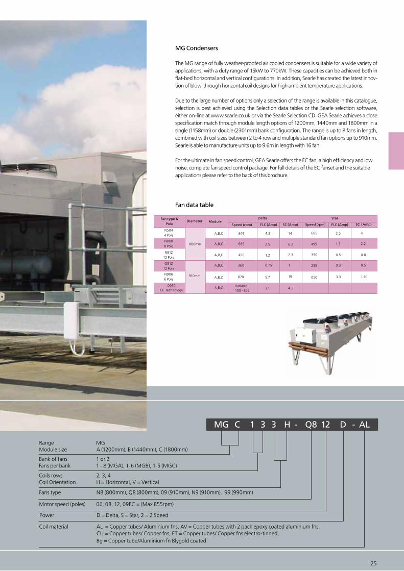
MG Condensers
The MG range of fully weather-proofed air cooled condensers is suitable for a wide variety of applications, with a duty range of 15kW to 770kW. These capacities can be achieved both in flat-bed horizontal and vertical configurations. In addition, Searle has created the latest innov-tion of blow-through horizontal coil designs for high ambient temperature applications.
Due to the large number of options only a selection of the range is available in this catalogue, selection is best achieved using the Selection data tables or the Searle selection software, either on-line at www.searle.co.uk or via the Searle Selection CD. GEA Searle achieves a close specification match through module length options of 1200mm, 1440mm and 1800mm in a single (1158mm) or double (2301mm) bank configuration. The range is up to 8 fans in length, combined with coil sizes between 2 to 4 row and multiple standard fan options up to 910mm. Searle is able to manufacture units up to 9.6m in length with 16 fan.
For the ultimate in fan speed control, GEA Searle offers the EC fan, a high efficiency and lownoise, complete fan speed control package. For full details of the EC fanset and the suitableapplications please refer to the back of this brochure.
Fan data table
0.75 255 0.3 0.5
870 5.7 650 3.3 1.10
3.1 4.3
1.2 350 0.5 0.8
A,B,C 4.3
2.5
360
450
895
665
1
19
2.3
14
6.2
A,B,C
A,B,C
A,B,C
A,B,C
A,B,C
800mm
910mm
Variable100 - 855
N8088 Pole
Q81212 Pole
N9066 Pole
09ECEC Technology
N5044 Pole
N812 12 Pole
Fan type &Pole
Diameter ModuleSpeed (rpm)
Delta
FLC (Amp) SC (Amp)
Star
Speed (rpm) FLC (Amp) SC (Amp)
495 1.3 2.2
685 2.5 4
MG C 1 3 3 H - Q8 12 D - AL
Range MGModule size A (1200mm), B (1440mm), C (1800mm)
Fans type N8 (800mm), Q8 (800mm), 09 (910mm), N9 (910mm), 99 (990mm)
Power D = Delta, S = Star, 2 = 2 Speed
Coil material AL = Copper tubes/ Aluminium fns, AV = Copper tubes with 2 pack epoxy coated aluminium fns. CU = Copper tubes/ Copper fns, ET = Copper tubes/ Copper fns electro-tinned, Bg = Copper tube/Aluminium fn Blygold coated
Motor speed (poles) 06, 08, 12, 09EC = (Max 855rpm)
Bank of fans 1 or 2Fans per bank 1 - 8 (MGA), 1-6 (MGB), 1-5 (MGC)
Coils rows 2, 3, 4Coil Orientation H = Horizontal, V = Vertical
24 25

26 27
MG 910mm 6 pole selection data
MGB112 52.2 52 2170 E 43.7 5.31 45 1490 E 72 17 5.4MGA113 55.5 54 2370 E 45.0 4.15 46 1570 E 89 20 6.3MGC112 60.0 52 2060 E 50.6 5.78 45 1450 D 89 20 6.3MGA114 62.2 56 2420 E 48.5 3.74 47 1590 D 119 26 8.2MGB113 64.1 53 2270 E 51.6 4.67 45 1540 D 107 23 7.3MGB114 69.8 52 2340 E 56.2 4.25 46 1560 D 143 30 9.5MGC113 74.2 52 2160 D 60.8 5.25 45 1500 D 134 28 8.8MGC114 80.8 52 2220 D 65.7 4.85 45 1530 D 179 36 11.4MGA212 90.9 56 4550 E 78.7 9.67 48 3060 E 119 26 8.2MGB212 104.4 55 6510 E 87.3 10.63 48 4490 E 143 33 10.4MGB122 104.8 55 4340 E 87.7 10.63 48 2990 E 143 30 9.5MGA213 110.9 57 4740 E 88.4 8.30 49 3140 E 179 40 12.6MGA123 111.2 57 4740 E 88.5 8.30 49 3140 E 179 36 11.4MGC212 120.0 55 4130 E 101.3 94.0 48 2910 D 179 40 12.6MGA214 124.4 58 4850 E 99.9 7.47 50 3180 D 239 51 16.1MGB213 128.2 56 6830 E 103.2 9.34 48 4620 E 215 46 14.5MGB214 144.3 55 7040 E 114.4 8.50 49 4700 E 286 60 19.0MGB124 145.5 55 4690 D 116.0 8.50 49 3130 D 286 55 17.4MGC213 148.4 55 4320 D 121.7 10.49 48 3000 D 268 56 17.7MGB132 157.5 57 6510 E 131.5 15.94 49 4490 E 215 42 13.3MGC214 166.5 55 4450 D 135.1 9.70 48 3060 D 358 72 22.8MGC124 166.9 55 4450 D 135.4 9.70 48 3060 D 358 70 22.1MGA133 168.9 59 7110 E 135.9 12.46 51 4710 E 268 54 17.1
MGB142 204.0 58 8680 E 168.9 21.25 50 5990 E 286 57 18.0 MGB222 209.6 58 8680 E 175.4 21.25 51 5990 E 286 59 18.6MGB134 211.3 57 7040 D 169.5 12.74 51 4700 D 429 82 25.9MGA223 222.4 60 9490 E 177.0 16.61 52 6290 E 358 72 22.8
MGA143 225.6 60 9490 E 180.7 16.61 52 6290 E 358 69 21.8MGC134 243.2 57 6680 D 197.6 14.54 50 4590 D 537 101 31.9
MGB152 260.5 59 10850 E 216.6 26.57 51 7490 E 358 69 21.8MGA153 281.3 61 11860 E 226.7 20.76 53 7860 E 447 86 27.2
MGB144 282.8 58 9390 D 225.9 16.99 51 6260 D 572 108 34.1MGB224 291.0 58 9390 D 232.1 16.99 52 6260 D 572 110 34.8MGC152 299.9 59 10320 E 253.2 28.88 52 7260 E 448 86 27.2MGB162 313.1 60 13020 E 261.9 31.88 52 8990 E 429 82 25.9 MGB232 314.9 60 13020 E 263.0 31.88 52 8990 E 429 84 26.5MGC144 323.1 58 8910 D 264.6 19.39 50 6120 D 715 133 42.0MGC224 333.9 58 8910 D 270.7 19.39 51 6120 D 715 139 43.9
MGA163 334.1 62 14230 E 265.8 24.91 53 9430 E 537 102 32.2MGA233 337.8 62 14230 E 271.9 24.91 54 9430 E 537 108 34.1
MGB154 351.0 59 11730 E 282.5 21.24 52 7830 D 715 133 42.0MGA182 363.4 62 18220 E 314.8 38.66 54 12260 E 480 91 29.0MGC153 371.1 59 10820 304.2 26.25 51 7520 E 671 117 39.9MGB163 384.7 60 13670 E 309.6 28.01 53 9250 E 644 122 38.4MGA173 388.3 63 16610 315.2 29.06 54 11000 E 627 119 37.4
MGC154 404.1 59 11140 D 328.6 24.24 51 7660 E 894 166 52.2
MGB242 408.1 61 17360 E 337.9 42.51 53 11990 E 572 113 35.7MGB164 419.0 60 14080 E 337.4 25.49 53 9400 E 858 159 50.2
MGB234 430.3 61 14050 D 348.5 25.49 53 9400 D 858 164 51.8MGA183 443.8 64 18980 E 360.3 33.21 55 12580 E 716 135 42.6
MGA243 451.2 63 18980 E 361.4 33.21 55 12580 E 715 139 43.9MGA184 497.6 65 19410 E 388.3 29.94 57 12730 E 954 176 55.6
MGC234 501.2 60 13370 D 406.3 29.09 52 9190 D 1073 201 63.5MGB252 521.0 61 21700 433.2 53.14 54 14980 E 715 138 43.6
MGA253 562.5 64 23720 453.3 41.52 55 15720 E 894 173 54.7
MGB244 576.4 62 18730 464.7 33.98 54 12530 D 1145 217 68.6MGC252 599.9 61 20650 506.3 57.77 54 14530 E 894 172 54.2MGB262 626.1 63 26040 523.8 63.76 55 26940 E 858 165 52.0MGC244 665.2 60 17830 543.7 38.78 53 12250 D 1431 266 84.1
MGA263 668.2 64 28470 E 531.5 49.82 56 18870 E 1073 204 64.5 MGB254 714.9 63 23420 D 580.2 42.48 55 15670 D 1431 266 84.1
MGA282 726.8 65 36440 629.6 77.33 57 24530 E 953 183 58.2MGC253 742.2 61 21640 D 608.4 52.50 54 9020 E 1342 253 80.0MGB263 769.4 63 27340 619.3 56.02 55 18510 E 1280 243 76.8
MGA112 45.4 53 2270 E 39.4 4.83 45 1530 E 60 13 4.16.27
6.835.647.345.226.265.98
13.66
12.546.55
6.86
13.66
11.2711.27
15.00
12.5210.00
11.96
14.00
11.96
20.4913.1013.10
16.9127.3227.32
17.9322.54
28.1834.1519.6422.54
23.91
36.6923.91
40.98
26.1940.98
26.19
33.81
33.81
29.89
34.3050.17
37.57
32.74
39.45
54.64
35.22
35.87
45.08
41.79
45.08
39.29
56.36
68.30
46.96
81.9673.38
52.39
58.7067.63
100.35
75.1568.61
Delta (High speed) Star (Low Speed)
Model
Capacity*
R404A&
R507A
kW Wm3/s dB(A)
Airvolume
Soundlevel**
Powerinput Energy
rating
kW Wm3/s dB(A)
Total surface
R404A Charge
Internalvolume
m2 dm3 kg
Airvolume
Powerinput Energy
rating
Capacity*
Soundlevel **
R404A&
R507A
EEEEEEE
EED
D
E
EE
E
EE
E
DD
ED
DE
EEDE
EE
DE
D
ED
E
DE
D
E
E
E
DE
E
D
E
E
D
E
E
E
EDE
E
DE
ED
E
Note: * Capacity quoted at 15 K DT1 Dew Point, ** Sound level quoted as mean pressure level at 10m
26 27
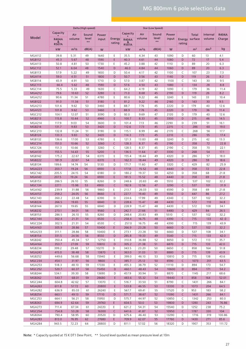
MGA112 39.8 5.31 49 1640 E 35.5 4.34 43 1090 D 60 13 4.1MGB112 45.3 5.67 48 1590 E 40.3 4.61 44 1080 D 72 17 5.4
MGC112 52.1 6.04 48 1540 D 46.0 4.84 44 1060 D 89 20 6.3
MGA113 50.8 4.81 50 1730 E 45.2 3.88 42 1110 D 89 20 6.3
MGA123 101.8 9.62 53 3460 E 88.9 7.76 45 2220 D 179 36 11.4
MGA133 155.5 14.43 55 5200 E 136.5 11.64 47 3330 D 268 54 17.1
MGA143 207.5 19.24 56 6930 E 181.5 15.52 48 4440 D 358 69 21.8
MGA153 259.2 24.05 56 8660 E 227.7 19.40 49 5550 D 447 86 27.2
MGA163 305.9 28.86 57 10400 E 266.9 23.28 50 6660 D 537 102 32.2
MGA213 101.6 9.62 53 3460 E 88.7 7.76 45 2220 D 179 40 12.6
MGA223 203.7 19.24 56 6930 E 177.8 15.52 48 4440 D 358 72 22.8
MGA243 415.0 38.48 58 13870 E 363.0 31.03 51 8880 D 715 139 43.9
MGA253 518.3 48.10 59 17330 E 455.3 38.79 52 11110 D 894 173 54.7
MGA263 611.8 57.72 60 20800 E 533.8 46.55 53 13330 D 1073 204 64.5
MGA273 711.4 67.34 61 24220 E 621.2 54.31 54 15540 D 1252 238 75.2
MGA283 813.0 76.95 62 27680 E 709.9 62.07 55 17760 D 1430 271 85.6
MGB113 57.9 5.22 49 1650 D 50.4 4.17 42 1100 C 107 23 7.3
MGB153 286.5 26.10 55 8260 D 248.6 20.83 49 5510 C 537 102 32.2
MGB213 115.8 10.44 52 4960 E 100.7 8.33 45 3300 D 215 46 14.5
MGB263 694.9 62.64 59 29760 E 604.5 50.0 53 19800 D 1280 243 76.86
MGC143 260.2 22.48 54 6390 D 224.6 17.99 49 4340 C 537 102 32.2
MGC253 664.1 56.21 58 15950 D 575.7 44.97 52 10850 C 1342 253 80.0
MGA114 59.0 4.51 51 1800 D 50.7 3.56 43 1140 D 119 26 8.2
MGA164 353.7 27.09 59 10810 D 305.2 21.38 51 6870 D 715 133 42.0
MGA214 117.9 9.03 54 3600 D 101.4 7.13 46 2290 D 239 51 16.1
MGA284 943.5 72.23 64 28800 D 811.1 57.02 56 18320 D 1907 353 111.72
MGB124 133.3 9.83 52 3420 D 114.3 7.73 45 2210 C 286 55 17.4
MGB134 199.6 14.74 54 5130 D 171.7 11.60 47 3320 C 429 82 25.9
MGB144 267.0 19.65 55 6840 D 228.9 15.47 48 4430 C 572 108 34.1
MGB154 331.5 24.56 56 8550 D 285.8 19.33 49 5540 C 715 133 42.0
MGB214 131.7 9.83 53 3420 D 112.6 7.73 45 2215 C 286 60 19.0
MGB224 266.5 19.65 55 6840 D 228.6 15.47 48 4430 C 572 110 34.8
MGB234 399.2 29.48 57 10270 D 343.5 23.20 50 6650 C 858 164 51.8
MGB244 534.1 39.30 58 13690 D 457.9 30.94 51 8870 C 1145 217 68.6
MGB254 663.1 49.13 59 17110 D 571.7 38.67 52 11090 C 1431 266 84.1
MGC124 151.3 10.66 51 3260 C 128.5 8.37 45 2190 C 358 70 22.1
MGC134 227.1 15.98 53 4900 C 192.9 12.56 47 3290 C 537 101 31.9
MGC144 302.4 21.31 54 6530 C 258.4 16.75 48 4390 C 715 133 42 .0
MGC214 151.0 10.66 52 3260 C 128.3 8.37 45 2190 C 358 72 22.8
MGC224 302.5 21.31 54 6530 C 257.0 16.75 48 4390 C 715 139 43.9
MGC234 454.1 31.97 56 9800 C 385.7 25.12 50 6590 C 1073 201 63.5
MGC244 604.8 42.62 57 13070 C 516.7 33.50 51 8790 C 1431 266 84.1
MGC114 75.5 5.33 49 1630 C 64.2 4.19 42 1090 C 179 36 11.4MGC113 66.4 5.62 48 1590 D 57.6 4.50 43 1080 C 134 28 8.8MGB114 65.9 4.91 50 1710 D 57.0 3.87 42 1100 C 143 30 9.5
MGA212 79.6 10.63 52 3280 E 71.0 8.68 45 2190 D 119 26 8.2
MGC212 104.1 12.07 51 3090 D 92.0 9.69 47 2120 D 179 40 12.6
MGA212 90.6 11.34 51 4780 E 80.6 9.22 46 3240 E 143 33 10.4
MGB122 91.0 11.34 51 3180 E 81.2 9.22 46 2160 D 143 30 9.5
MGC213 132.8 11.24 51 3190 D 115.1 8.99 46 2170 C 268 56 17.7
MGB132 136.6 17.00 53 4780 E 121.3 13.83 48 3240 D 215 42 13.3
MGB142 175.2 22.67 54 6370 E 155.4 18.44 49 4320 D 286 57 18.0MGB222 181.9 22.67 54 6370 E 162.3 18.44 49 4320 D 286 59 18.6
MGC142 205.5 24.15 54 6180 D 180.2 19.37 50 4250 D 358 68 21.8
MGA162 239.9 31.88 56 9860 E 213.7 26.03 50 6590 D 358 69 21.8
MGB232 273.1 34.01 56 9560 E 242.7 27.66 51 6480 D 429 84 26.5MGB153 286.5 26.10 55 8260 D 248.6 20.83 49 5510 C 537 102 32.2
MGA233 311.1 28.86 58 10400 E 273.1 23.28 50 6660 D 537 108 34.1
MGB242 350.4 45.34 57 12750 E 310.8 36.88 52 8650 D 572 113 35.7
MGB252 449.6 56.68 58 15940 E 399.0 46.10 53 10810 D 715 138 43.6
MGC252 520.7 60.37 58 15450 D 460.1 48.43 54 10600 D 894 171 54.2
MGB262 543.7 68.01 59 28680 E 483.6 55.32 54 19440 E 858 164 52.01
MGA282 636.9 85.03 61 26240 E 567.7 69.41 55 17520 D 953 183 58.2
MGC254 754.8 53.28 58 16300 C 641.6 41.87 52 10950 C 1787 330 104MGB264 790.4 58.95 60 20520 D 675.6 46.40 53 13290 C 1716 319 100.86
MG 800mm 6 pole selection data
Note: * Capacity quoted at 15 K DT1 Dew Point, ** Sound level quoted as mean pressure level at 10m
Delta (High speed) Star (Low Speed)
Model
Capacity*
R404A&
R507A
kW Wm3/s dB(A)
Airvolume
Soundlevel**
Powerinput Energy
rating
kW Wm3/s dB(A)
Total surface
R404A Charge
Internalvolume
m2 dm3 kg
Airvolume
Powerinput Energy
rating
Capacity*
Soundlevel **
R404A&
R507A
28 29
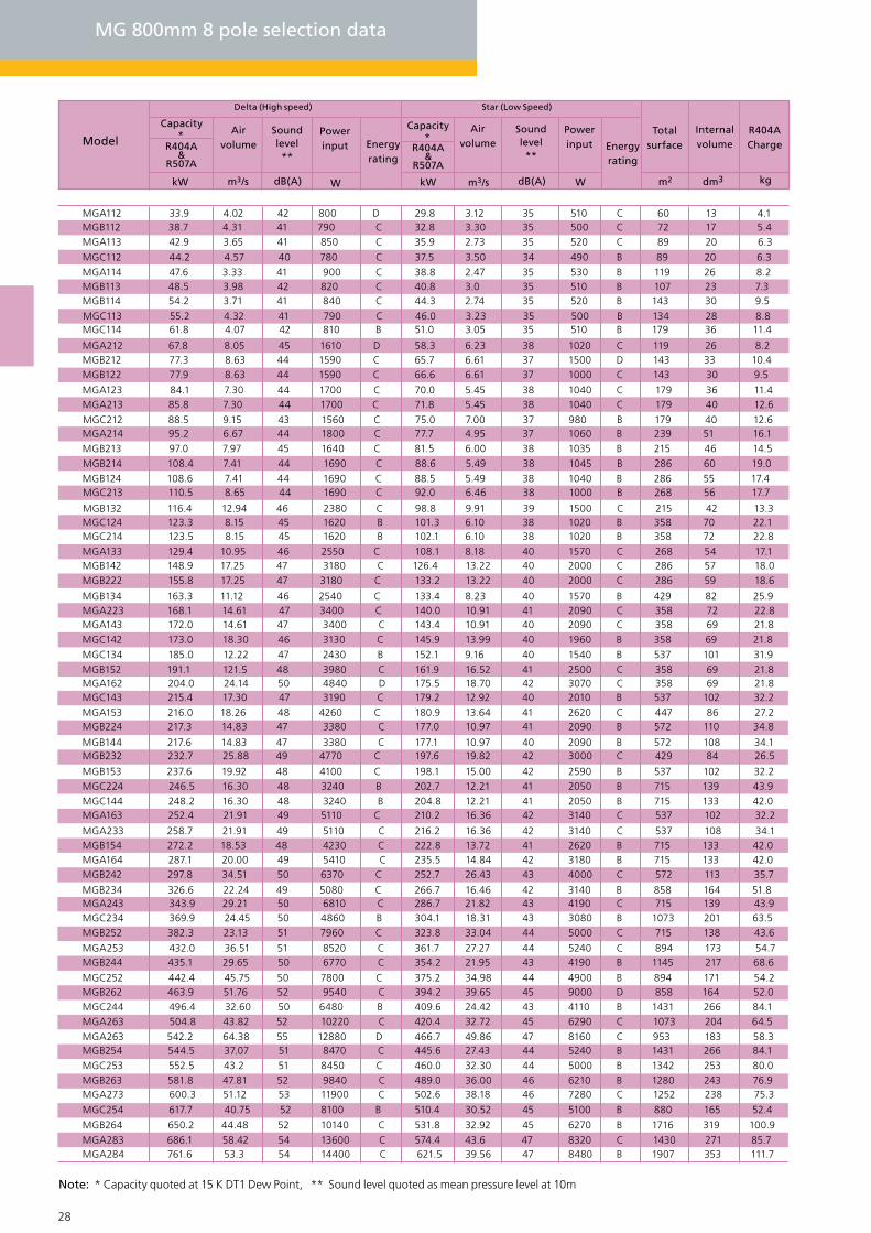
MG 800mm 8 pole selection data
MGA112 33.9 4.02 42 800 D 29.8 3.12 35 510 C 60 13 4.1
MGC212 88.5 9.15 43 1560 C 75.0 7.00 37 980 B 179 40 12.6
MGA113 42.9 3.65 41 850 C 35.9 2.73 35 520 C 89 20 6.3
MGA123 84.1 7.30 44 1700 C 70.0 5.45 38 1040 C 179 36 11.4MGA213 85.8 7.30 44 1700 C 71.8 5.45 38 1040 C 179 40 12.6
MGB113 48.5 3.98 42 820 C 40.8 3.0 35 510 B 107 23 7.3
MGB213 97.0 7.97 45 1640 C 81.5 6.00 38 1035 B 215 46 14.5
MGB263 581.8 47.81 52 9840 C 489.0 36.00 46 6210 B 1280 243 76.9
MGC113 55.2 4.32 41 790 C 46.0 3.23 35 500 B 134 28 8.8
MGC143 215.4 17.30 47 3190 C 179.2 12.92 40 2010 B 537 102 32.2
MGC213 110.5 8.65 44 1690 C 92.0 6.46 38 1000 B 268 56 17.7
MGC253 552.5 43.2 51 8450 C 460.0 32.30 44 5000 B 1342 253 80.0
MGA114 47.6 3.33 41 900 C 38.8 2.47 35 530 B 119 26 8.2
MGA214 95.2 6.67 44 1800 C 77.7 4.95 37 1060 B 239 51 16.1
MGA284 761.6 53.3 54 14400 C 621.5 39.56 47 8480 B 1907 353 111.7
MGB114 54.2 3.71 41 840 C 44.3 2.74 35 520 B 143 30 9.5
MGB124 108.6 7.41 44 1690 C 88.5 5.49 38 1040 B 286 55 17.4
MGB144 217.6 14.83 47 3380 C 177.1 10.97 40 2090 B 572 108 34.1
MGB154 272.2 18.53 48 4230 C 222.8 13.72 41 2620 B 715 133 42.0
MGB214 108.4 7.41 44 1690 C 88.6 5.49 38 1045 B 286 60 19.0
MGB224 217.3 14.83 47 3380 C 177.0 10.97 41 2090 B 572 110 34.8
MGB244 435.1 29.65 50 6770 C 354.2 21.95 43 4190 B 1145 217 68.6
MGB254 544.5 37.07 51 8470 C 445.6 27.43 44 5240 B 1431 266 84.1
MGB264 650.2 44.48 52 10140 C 531.8 32.92 45 6270 B 1716 319 100.9
MGC114 61.8 4.07 42 810 B 51.0 3.05 35 510 B 179 36 11.4
MGC124 123.3 8.15 45 1620 B 101.3 6.10 38 1020 B 358 70 22.1
MGC134 185.0 12.22 47 2430 B 152.1 9.16 40 1540 B 537 101 31.9
MGC144 248.2 16.30 48 3240 B 204.8 12.21 41 2050 B 715 133 42.0
MGC214 123.5 8.15 45 1620 B 102.1 6.10 38 1020 B 358 72 22.8
MGC224 246.5 16.30 48 3240 B 202.7 12.21 41 2050 B 715 139 43.9
MGC234 369.9 24.45 50 4860 B 304.1 18.31 43 3080 B 1073 201 63.5
MGC244 496.4 32.60 50 6480 B 409.6 24.42 43 4110 B 1431 266 84.1
MGC254 617.7 40.75 52 8100 B 510.4 30.52 45 5100 B 880 165 52.4
MGB112 38.7 4.31 41 790 C 32.8 3.30 35 500 C 72 17 5.4
MGC112 44.2 4.57 40 780 C 37.5 3.50 34 490 B 89 20 6.3
MGA212 67.8 8.05 45 1610 D 58.3 6.23 38 1020 C 119 26 8.2MGB212 77.3 8.63 44 1590 C 65.7 6.61 37 1500 D 143 33 10.4MGB122 77.9 8.63 44 1590 C 66.6 6.61 37 1000 C 143 30 9.5
MGC252 442.4 45.75 50 7800 C 375.2 34.98 44 4900 B 894 171 54.2
MGA143 172.0 14.61 47 3400 C 143.4 10.91 40 2090 C 358 69 21.8
MGA153 216.0 18.26 48 4260 C 180.9 13.64 41 2620 C 447 86 27.2
MGA163 252.4 21.91 49 5110 C 210.2 16.36 42 3140 C 537 102 32.2
MGA223 168.1 14.61 47 3400 C 140.0 10.91 41 2090 C 358 72 22.8
MGA233 258.7 21.91 49 5110 C 216.2 16.36 42 3140 C 537 108 34.1
MGA243 343.9 29.21 50 6810 C 286.7 21.82 43 4190 C 715 139 43.9
MGA253 432.0 36.51 51 8520 C 361.7 27.27 44 5240 C 894 173 54.7
MGA263 504.8 43.82 52 10220 C 420.4 32.72 45 6290 C 1073 204 64.5
MGA273 600.3 51.12 53 11900 C 502.6 38.18 46 7280 C 1252 238 75.3
MGA283 686.1 58.42 54 13600 C 574.4 43.6 47 8320 C 1430 271 85.7
MGB153 237.6 19.92 48 4100 C 198.1 15.00 42 2590 B 537 102 32.2
MGB132 116.4 12.94 46 2380 C 98.8 9.91 39 1500 C 215 42 13.3
MGA133 129.4 10.95 46 2550 C 108.1 8.18 40 1570 C 268 54 17.1MGB142 148.9 17.25 47 3180 C 126.4 13.22 40 2000 C 286 57 18.0MGB222 155.8 17.25 47 3180 C 133.2 13.22 40 2000 C 286 59 18.6
MGB134 163.3 11.12 46 2540 C 133.4 8.23 40 1570 B 429 82 25.9
MGC142 173.0 18.30 46 3130 C 145.9 13.99 40 1960 B 358 69 21.8
MGB152 191.1 121.5 48 3980 C 161.9 16.52 41 2500 C 358 69 21.8MGA162 204.0 24.14 50 4840 D 175.5 18.70 42 3070 C 358 69 21.8
MGB232 232.7 25.88 49 4770 C 197.6 19.82 42 3000 C 429 84 26.5
MGA164 287.1 20.00 49 5410 C 235.5 14.84 42 3180 B 715 133 42.0MGB242 297.8 34.51 50 6370 C 252.7 26.43 43 4000 C 572 113 35.7
MGB234 326.6 22.24 49 5080 C 266.7 16.46 42 3140 B 858 164 51.8
MGB252 382.3 23.13 51 7960 C 323.8 33.04 44 5000 C 715 138 43.6
MGB262 463.9 51.76 52 9540 C 394.2 39.65 45 9000 D 858 164 52.0
MGA263 542.2 64.38 55 12880 D 466.7 49.86 47 8160 C 953 183 58.3
Delta (High speed) Star (Low Speed)
Model
Capacity*
R404A&
R507A
kW Wm3/s dB(A)
Airvolume
Soundlevel**
Powerinput Energy
rating
kW Wm3/s dB(A)
Total surface
R404A Charge
Internalvolume
m2 dm3 kg
Airvolume
Powerinput Energy
rating
Capacity*
Soundlevel **
R404A&
R507A
Note: * Capacity quoted at 15 K DT1 Dew Point, ** Sound level quoted as mean pressure level at 10m
28 29
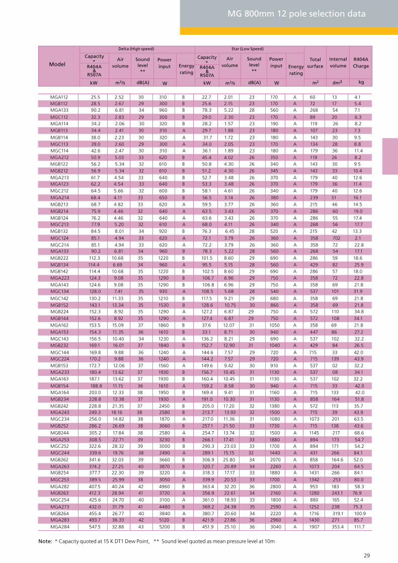
MG 800mm 12 pole selection data
Delta (High speed) Star (Low Speed)
Model
Capacity*
R404A&
R507A
kW Wm3/s dB(A)
Airvolume
Soundlevel**
Powerinput Energy
rating
kW Wm3/s dB(A)
Total surface
R404A Charge
Internalvolume
m2 dm3 kg
Airvolume
Powerinput Energy
rating
Capacity*
Soundlevel **
R404A&
R507A
MGA162 153.5 15.09 37 1860 B 37.6 12.07 31 1050 A 358 69 21.8
MGA212 50.9 5.03 33 620 B 45.4 4.02 26 350 A 119 26 8.2
MGA282 407.5 40.24 42 4960 B 363.4 32.20 36 2800 A 953 183 58.3
MGB112 28.5 2.67 29 300 B 25.6 2.15 23 170 A 72 17 5.4
MGB122 56.2 5.34 32 610 B 50.8 4.30 26 340 A 143 30 9.5
MGB132 84.5 8.01 34 920 B 76.3 6.45 28 520 A 215 42 13.3
MGB142 114.4 10.68 35 1220 B 102.5 8.60 29 690 A 286 57 18.0
MGB212 56.9 5.34 32 610 B 51.2 4.30 26 345 A 143 33 10.4
MGB222 112.3 10.68 35 1220 B 101.5 8.60 29 690 A 286 59 18.6
MGB232 169.1 16.01 37 1840 B 152.7 12.90 31 1040 A 429 84 26.5
MGB242 228.8 21.35 37 2450 B 205.0 17.20 32 1380 A 572 113 35.7
MGB252 286.2 26.69 38 3060 B 257.1 21.50 33 1730 A 715 138 43.6
MGB262 341.6 32.03 39 3660 B 306.9 25.80 34 2070 A 858 164.6 52.0
MGC112 32.3 2.83 29 300 B 29.0 2.30 23 170 A 89 20 6.3
MGC142 130.2 11.33 35 1210 B 117.5 9.21 29 680 A 358 69 21.8
MGC212 64.5 5.66 32 600 B 58.1 4.61 26 340 A 179 40 12.6
MGC252 322.6 28.32 39 3000 B 290.3 23.03 33 1700 A 894 171 54.2
MGA123 62.2 4.54 33 640 B 53.3 3.48 26 370 A 179 36 11.4
MGA133 90.2 6.81 34 960 B 78.3 5.22 28 560 A 268 54 7.1
MGA143 124.6 9.08 35 1290 B 106.8 6.96 29 750 A 358 69 21.8
MGA153 154.3 11.35 36 1610 B 33.1 8.71 30 940 A 447 86 27.2
MGA163 187.1 13.62 37 1930 B 160.4 10.45 31 1130 A 537 102 32.2
MGA213 61.7 4.54 33 640 B 52.7 3.48 26 370 A 179 40 12.6
MGA223 124.3 9.08 35 1290 B 106.7 6.96 29 750 A 358 72 22.8
MGA233 180.4 13.62 37 1930 B 156.7 10.45 31 1130 A 537 08 34.1
MGA243 249.3 18.16 38 2580 B 213.7 13.93 32 1500 A 715 39 43.9
MGA253 308.5 22.71 39 3230 B 266.1 17.41 33 1880 A 894 173 54.7
MGA263 374.2 27.25 40 3870 B 320.7 20.89 34 2260 A 1073 204 64.5
MGA273 432.0 31.79 41 4480 B 369.2 24.38 35 2590 A 1252 238 75.3
MGA283 493.7 36.33 42 5120 B 421.9 27.86 36 2960 A 1430 271 85.7
MGB113 34.4 2.41 30 310 A 29.7 1.88 23 180 A 107 23 7.3
MGB153 172.7 12.06 37 1560 A 149.6 9.42 30 910 A 537 02 32.2
MGB213 68.7 4.82 33 620 A 59.5 3.77 26 360 A 215 46 14.5
MGB263 412.3 28.94 41 3720 A 356.9 22.61 34 2160 A 1280 243.1 76.9
MGC113 39.0 2.60 29 300 A 34.0 2.05 23 170 A 134 28 8.8
MGC143 156.5 10.40 34 1230 A 136.2 8.21 29 690 A 537 102 32.2
MGC213 77.9 5.20 32 610 A 68.0 4.11 26 340 A 268 56 17.7
MGC253 389.5 25.99 38 3050 A 339.9 20.53 33 1700 A 1342 253 80.0
MGA114 34.2 2.06 30 320 B 28.2 1.57 23 190 A 119 26 8.2
MGA164 203.0 12.33 38 1950 B 169.4 9.41 31 1160 A 715 133 42.0
MGA214 68.4 4.11 33 650 B 56.5 3.14 26 380 A 239 51 16.1
MGA284 547.5 32.88 43 5200 B 451.9 25.10 36 3040 A 1907 353.4 111.7
MGB114 38.0 2.23 30 320 A 31.7 1.72 23 180 A 143 30 9.5
MGB124 76.2 4.46 32 640 A 63.6 3.43 26 370 A 286 55 17.4
MGB134 114.4 6.69 34 960 A 95.5 5.15 28 560 A 429 82 25.9
MGB144 152.6 8.92 35 1290 A 127.4 6.87 29 750 A 572 108 34.1
MGB154 188.8 11.15 36 1610 A 159.2 8.58 30 940 A 715 33 42.0
MGB214 75.9 4.46 32 640 A 63.5 3.43 26 370 A 286 60 19.0
MGB224 152.3 8.92 35 1290 A 127.2 6.87 29 750 A 572 110 34.8
MGB234 228.8 13.38 37 1930 A 191.0 10.30 31 1130 A 858 164 51.8
MGB244 305.2 17.84 38 2580 A 254.7 13.74 32 1500 A 1145 217 68.6
MGB254 377.7 22.30 39 3220 A 318.3 17.17 33 1880 A 1431 266 84.1
MGB264 455.4 26.77 40 3840 A 380.7 20.60 34 2220 A 1716 319.1 100.9
MGC114 42.6 2.47 30 310 A 36.1 1.89 23 180 A 179 36 11.4
MGC124 85.1 4.94 33 620 A 72.1 3.79 26 360 A 358 702 2.1
MGC134 128.0 7.41 35 930 A 108.5 5.68 28 540 A 537 101 31.9
MGC144 169.8 9.88 36 1240 A 144.6 7.57 29 720 A 715 33 42.0
MGC214 85.1 4.94 33 620 A 72.2 3.79 26 360 A 358 72 22.8
MGC224 170.2 9.88 36 1240 A 144.2 7.57 29 720 A 715 139 43.9
MGC234 256.0 14.82 38 1870 A 217.0 11.36 31 1080 A 1073 201 63.5
MGC244 339.6 19.76 38 2490 A 289.1 15.15 32 1440 A 431 266 84.1
MGC254 425.6 24.70 40 3100 A 361.0 18.93 33 1800 A 880 165 52.4
MGA133 90.2 6.81 34 960 B 78.3 5.22 28 560 A 268 54 17.1
MGB152 143.1 13.34 35 1530 B 128.6 10.75 30 860 A 358 69 21.8
MGA112 25.5 2.52 30 310 B 22.7 2.01 23 170 A 60 13 4.1
Note: * Capacity quoted at 15 K DT1 Dew Point, ** Sound level quoted as mean pressure level at 10m

30 31
GEA Searle - MG Model drawings & Dimensions
1 fixing hole in base
of each leg 15.0
1 B
ank
2 B
ank
Horizontal unit Vertical unit
Notes: All dimensions in mm. Common junction box will vary in size and position depending on the control option required.
63-05
2301
.0 O/
ALL C
ASEW
ORK
100.
0
25 . 0 25. 0
Optional fanisolator
1078 Fixing centres
Hot Gas
Liquid
CommomJ/Box
1158
Ove
rall
case
wor
k
1200 Fixing centre
Optional fanisolator
Indivdualfan isolator(optional)
4040
500
495
270
2221 Fixing centres
2301 Overall casework
1200 Fixing centres
2301
Ove
rall
case
wor
k
5050100
377 495 270Tranist leg63 - 051
4040
500
495
270
1265
100
50 50
377 495 270
4040
70 215
MG Model drawings & Dimensions
C
B1 B2
A
1158 Overall casework
1 fixing hole in base
of each leg 15.0
1265
Optional fanisolator

30 31
Notes: Total unit dry weight is dependent upon the coil material used (AL/AV = Copper tubes with Aluminium or Copper tubes with 2 pack epoxy coated aluminium fns, CU = Copper tubes with Copper fins or Copper fins electro-tinned).
Model
kg kg kg kg
AL ALCU AL
* 1 Bank * 2 Bank
Total unit Dry weight
Fanbanks
Fansper
bankmm mm mm mm
CB2B1A
MGA_12
1516 2109
1580 1926
1778 2298
1977 2669
1796 2192
2022 2617
1516 1840
1720 2253
1924 2635
1458 1828
1669 2225
1881 2623
740 962 1346 1791
656 804 1177 1473
638 860 1166 1611
574 740 1038 1372
510 621 921 1134
431 579 792 1088
388 499 707 929
346 420 622 777
239 313 435 583
218 274 392 503196 233 350 424
876 1172 1617 2210
790 1013 1447 1892
192 237 347 437
706 854 1278 1574
708 946 1306 1780
640 818 1169 1525
572 691 1034 1279
535 713 991 1346
484 617 889 1156433 522 786 964
372 491 686 924
339 428 618 796
304 363 551 670
210 269 382 501
176 205 314 373
913 1211 1700 2293830 1052 1530 1975745 893 1359 1656
775 1022 1437 1931
705 890 1296 1667
634 758 1154 1401622 827 1161 1556573 721 1047 1344
515 614 834 1132
476 624 881 1178
433 544 797 1019
390
1123
3582
3582
2381
2381
2381
3581
3581
2880
2880
2880
3581
3581
3581
3582
2682
2682
2682
3582
35823582
2862
2862
2862
3582
3582
3582
2982
2982
2982
2382
2382
2382
3542
3542
2341
2341
2341
3521
3521
2821
2821
2821
3541
3541
3541
3542
2642
2642
2642
3542
35423542
5822
5822
2822
3542
3542
3542
2942
2942
2942
23422342
2342
7203
7203
8403
8403
8403
9603
9603
8643
8643
8643
9003
9003
9003
7203
5403
5403
5403
3603
3603
3603
1803
1803
1803
7203
72037203
1443
5763
5763
5763
4323
43234323
2883
2883
2883
1443
1443
7203
7203
7203
6003
6003
6003
48034803
4803
3603
3603
36032403
2403
2403
12031203
120311 or 2
464 712 860
331 430 608 806
304 378 551 699
275 325 494 593
188 238 343 441
174 211 314 388
160 184 285 335
2250 3040
7120
7123
8323
8323
8323
9523
9523
8563
8563
8563
8923
8923
8923
7123
5323
5323
5323
3523
3523
3523
1723
17231723
7123
7123
7123
1363
5683
5683
5683
4243
42434243
2803
2803
2803
1363
1363
7123
7123
7123
5923
5923
5923
47234723
4723
3525
3524
3523
2323
2323
2323
1123
1123
9523358135219603
MGA_13 11 or 2MGA_14 11 or 2
MGA_22 21 or 2
MGA_23 21 or 2
MGA_24 21 or 2
MGA_32 31 or 2
MGA_33 31 or 2MGA_34 31 or 2
MGA_42 41 or 2
MGA_43 41 or 2
MGA_44 41 or 2
MGA_52 51 or 2MGA_53 51 or 2
MGA_54 51 or 2
MGA_62 61 or 2
MGA_63 61 or 2
MGA_64 61 or 2
MGA272 72
MGA273 72
MGA274 72
MGA282 82MGA283 8 2
MGA284 82
MGB_12 11 or 2
MGB_13 11 or 2
MGB_14 11 or 2
MGB_22 21 or 2MGB_23 21 or 2
MGB_24 21 or 2
MGB_32 31 or 2
MGB_33 31 or 2
MGB_34 31 or 2MGB_42 41 or 2
MGB_43 41 or 2
MGB_44 41 or 2
MGB_52 51 or 2
MGB_53 51 or 2
MGB_54 51 or 2
MGB262 62
MGB263 62
MGB264 62MGC_12 11 or 2
MGC_13 11 or 2
MGC_14 11 or 2
MGC_22 21 or 2
MGC_23 21 or 2
MGC_24 21 or 2MGC_32 31 or 2
MGC_33 31 or 2
MGC_34 31 or 2
MGC_42 41 or 2
MGC_43 41 or 2MGC_44 41 or 2
MGC252 52
MGC253 52
MGC254 52
826 1122

MM - MX Air Cooled Condensers
32 33

MM - MX Condensers
The MM and MX ranges of fully weather-proofed air cooled condensers feature a new range of coil module sizes to extend the coil surface to air volume ratio and thereby increase the “airvolume efficiency” factor. The MM series has a duty range of 18kW to 596kW and the MX series has a duty range of 22kW to 754kW.
Both ranges are available in flat-bed horizontal and vertical configurations and have the lat-est innovation of blow-through horizontal design for high temperature applications. The MM range is available in a single width of 1539mm and the MX range is available in a single width of 2301mm, both with module lengths of 1200mm, 1440mm and 1800mm, up to 8 fans and 2 to 4 coil rows.
The full fanset options are available, including the 910mm EC energy efficient fanset, whichenables a highly efficient, very low noise complete fan speed-control package. Full details ofthe EC fanset and ideal application areas can be found in the EC section.
Due to the wide variety of condensers available only a selection of the range is represented in this catalogue. For full selection data either refer to the Selection data tables or use the Searle selection software, either on-line or via the Searle Selection CD.
Fan data table
0.75 255 0.3 0.5
870 5.7 650 3.3 1.10
3.1 4.3
1.2 350 0.5 0.8
A,B,C 4.3
2.5
360
450
895
665
1
19
2.3
14
6.2
A,B,C
A,B,C
A,B,C
A,B,C
A,B,C
800mm
910mm
Variable100 - 855
N8088 Pole
Q81212 Pole
N9066 Pole
09ECEC Technology
N5044 Pole
N812 12 Pole
Fan type &Pole
Diameter ModuleSpeed (rpm)
Delta
FLC (Amp) SC (Amp)
Star
Speed (rpm) FLC (Amp) SC (Amp)
495 1.3 2.2
685 2.5 4
MM A 1 6 2 H - N8 12 D - AL
Range MM - MXModule size A (1200mm), B (1440mm), C (1800mm)
Fans type N8 (800mm), Q8 (800mm), 09 (910mm), N9 (910mm), 99 (990mm)
Power D = Delta, S = Star, 2 = 2 Speed, Variable speed
Coil material AL = Copper tubes/ Aluminium fns, AV = Copper tubes with 2 pack epoxy coated aluminium fns. CU = Copper tubes/ Copper fns, ET = Copper tubes/ Copper fns electro-tinned, Bg = Copper tube/Aluminium fn Blygold coated
Motor speed (poles) 06, 08, 12, 09EC = (Max 855rpm)
Bank of fans 1Fans per bank 1 - 8 (MMA & MXA), 1 - 6 (MMB & MXB), 1-5 (MMC & MXC),
Coils rows 2, 3, 4Coil Orientation H = Horizontal, V = Vertical
32 33
34 35
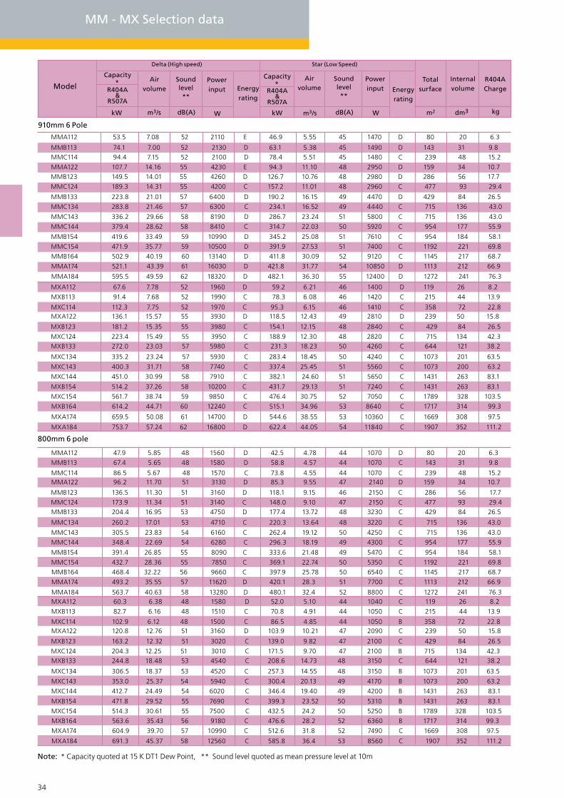
MM - MX Selection data
800mm 6 pole
910mm 6 Pole
MMA112 47.9 5.85 48 1560 D 42.5 4.78 44 1070 D 80 20 6.3
MMB113 67.4 5.65 48 1580 D 58.8 4.57 44 1070 C 143 31 9.8
MMC114 86.5 5.67 48 1570 C 73.8 4.55 44 1070 C 239 48 15.2MMA122 96.2 11.70 51 3130 D 85.3 9.55 47 2140 D 159 34 10.7
MMB123 136.5 11.30 51 3160 D 118.1 9.15 46 2150 C 286 56 17.7
MMC124 173.9 11.34 51 3140 C 148.0 9.10 47 2150 C 477 93 29.4MMB133 204.4 16.95 53 4750 D 177.4 13.72 48 3230 C 429 84 26.5
MMC134 260.2 17.01 53 4710 C 220.3 13.64 48 3220 C 715 136 43.0
MMC143 305.5 23.83 54 6160 C 262.4 19.12 50 4250 C 715 136 43.0
MMC144 348.4 22.69 54 6280 C 296.3 18.19 49 4300 C 954 177 55.9
MMB154 391.4 26.85 55 8090 C 333.6 21.48 49 5470 C 954 184 58.1
MMC154 432.7 28.36 55 7850 C 369.1 22.74 50 5350 C 1192 221 69.8
MMB164 468.4 32.22 56 9660 C 397.9 25.78 50 6540 C 1145 217 68.7
MMA174 493.2 35.55 57 11620 D 420.1 28.3 51 7700 C 1113 212 66.9
MMA184 563.7 40.63 58 13280 D 480.1 32.4 52 8800 C 1272 241 76.3MXA112 60.3 6.38 48 1580 D 52.0 5.10 44 1040 C 119 26 8.2
MXB113 82.7 6.16 48 1510 C 70.8 4.91 44 1050 C 215 44 13.9
MXC114 102.9 6.12 48 1500 C 86.5 4.85 44 1050 B 358 72 22.8MXA122 120.8 12.76 51 3160 D 103.9 10.21 47 2090 C 239 50 15.8
MXB123 163.2 12.32 51 3020 C 139.0 9.82 47 2100 C 429 84 26.5
MXC124 204.3 12.25 51 3010 C 171.5 9.70 47 2100 B 715 134 42.3MXB133 244.8 18.48 53 4540 C 208.6 14.73 48 3150 C 644 121 38.2
MXC134 306.5 18.37 53 4520 C 257.3 14.55 48 3150 B 1073 201 63.5
MXC143 353.0 25.37 54 5940 C 300.4 20.13 49 4170 B 1073 200 63.2
MXC144 412.7 24.49 54 6020 C 346.4 19.40 49 4200 B 1431 263 83.1
MXB154 471.8 29.52 55 7690 C 399.3 23.52 50 5310 B 1431 263 83.1
MXC154 514.3 30.61 55 7500 C 432.5 24.2 50 5250 B 1789 328 103.5
MXB164 563.6 35.43 56 9180 C 476.6 28.2 52 6360 B 1717 314 99.3
MXA174 604.9 39.70 57 10990 C 512.6 31.8 52 7490 C 1669 308 97.5
MXA184 691.3 45.37 58 12560 C 585.8 36.4 53 8560 C 1907 352 111.2
MMA112 53.5 7.08 52 2110 E 46.9 5.55 45 1470 D 80 20 6.3
MMB113 74.1 7.00 52 2130 D 63.1 5.38 45 1490 D 143 31 9.8MMC114 94.4 7.15 52 2100 D 78.4 5.51 45 1480 C 239 48 15.2
MMA122 107.7 14.16 55 4230 E 94.3 11.10 48 2950 D 159 34 10.7MMB123 149.5 14.01 55 4260 D 126.7 10.76 48 2980 D 286 56 17.7
MMC124 189.3 14.31 55 4200 C 157.2 11.01 48 2960 C 477 93 29.4
MMB133 223.8 21.01 57 6400 D 190.2 16.15 49 4470 D 429 84 26.5
MMC134 283.8 21.46 57 6300 C 234.1 16.52 49 4440 C 715 136 43.0
MMC143 336.2 29.66 58 8190 D 286.7 23.24 51 5800 C 715 136 43.0
MMC144 379.4 28.62 58 8410 C 314.7 22.03 50 5920 C 954 177 55.9
MMB154 419.6 33.49 59 10990 D 345.2 25.08 51 7610 C 954 184 58.1
MMC154 471.9 35.77 59 10500 D 391.9 27.53 51 7400 C 1192 221 69.8
MMB164 502.9 40.19 60 13140 D 411.8 30.09 52 9120 C 1145 217 68.7
MMA174 521.1 43.39 61 16030 D 421.8 31.77 54 10850 D 1113 212 66.9
MMA184 595.5 49.59 62 18320 D 482.1 36.30 55 12400 D 1272 241 76.3
MXA112 67.6 7.78 52 1960 D 59.2 6.21 46 1400 D 119 26 8.2
MXB113 91.4 7.68 52 1990 C 78.3 6.08 46 1420 C 215 44 13.9
MXC114 112.3 7.75 52 1970 C 95.3 6.15 46 1410 C 358 72 22.8MXA122 136.1 15.57 55 3930 D 118.5 12.43 49 2810 D 239 50 15.8
MXB123 181.2 15.35 55 3980 C 154.1 12.15 48 2840 C 429 84 26.5
MXC124 223.4 15.49 55 3950 C 188.9 12.30 48 2820 C 715 134 42.3MXB133 272.0 23.03 57 5980 C 231.3 18.23 50 4260 C 644 121 38.2
MXC134 335.2 23.24 57 5930 C 283.4 18.45 50 4240 C 1073 201 63.5
MXC143 400.3 31.71 58 7740 C 337.4 25.45 51 5560 C 1073 200 63.2
MXC144 451.0 30.99 58 7910 C 382.1 24.60 51 5650 C 1431 263 83.1
MXB154 514.2 37.26 58 10200 C 431.7 29.13 51 7240 C 1431 263 83.1
MXC154 561.7 38.74 59 9850 C 476.4 30.75 52 7050 C 1789 328 103.5
MXB164 614.2 44.71 60 12240 C 515.1 34.96 53 8640 C 1717 314 99.3
MXA174 659.5 50.08 61 14700 D 544.6 38.55 53 10360 C 1669 308 97.5
MXA184 753.7 57.24 62 16800 D 622.4 44.05 54 11840 C 1907 352 111.2
Delta (High speed) Star (Low Speed)
Model
Capacity*
R404A&
R507A
kW Wm3/s dB(A)
Airvolume
Soundlevel**
Powerinput Energy
rating
kW Wm3/s dB(A)
Total surface
R404A Charge
Internalvolume
m2 dm3 kg
Airvolume
Powerinput Energy
rating
Capacity*
Soundlevel **
R404A&
R507A
Note: * Capacity quoted at 15 K DT1 Dew Point, ** Sound level quoted as mean pressure level at 10m
34 35
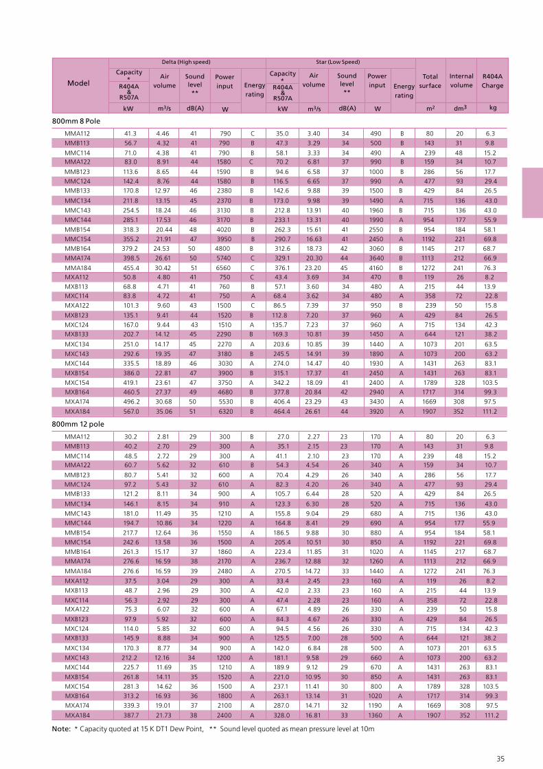
800mm 12 pole
MMA112 41.3 4.46 41 790 C 35.0 3.40 34 490 B 80 20 6.3
MMB113 56.7 4.32 41 790 B 47.3 3.29 34 500 B 143 31 9.8
MMC114 71.0 4.38 41 790 B 58.1 3.33 34 490 A 239 48 15.2MMA122 83.0 8.91 44 1580 C 70.2 6.81 37 990 B 159 34 10.7
MMB123 113.6 8.65 44 1590 B 94.6 6.58 37 1000 B 286 56 17.7
MMC124 142.4 8.76 44 1580 B 116.5 6.65 37 990 A 477 93 29.4MMB133 170.8 12.97 46 2380 B 142.6 9.88 39 1500 B 429 84 26.5
MMC134 211.8 13.15 45 2370 B 173.0 9.98 39 1490 A 715 136 43.0
MMC143 254.5 18.24 46 3130 B 212.8 13.91 40 1960 B 715 136 43.0
MMC144 285.1 17.53 46 3170 B 233.1 13.31 40 1990 A 954 177 55.9
MMB154 318.3 20.44 48 4020 B 262.3 15.61 41 2550 B 954 184 58.1
MMC154 355.2 21.91 47 3950 B 290.7 16.63 41 2450 A 1192 221 69.8
MMB164 379.2 24.53 50 4800 B 312.6 18.73 42 3060 B 1145 217 68.7
MMA174 398.5 26.61 50 5740 C 329.1 20.30 44 3640 B 1113 212 66.9
MMA184 455.4 30.42 51 6560 C 376.1 23.20 45 4160 B 1272 241 76.3MXA112 50.8 4.80 41 750 C 43.4 3.69 34 470 B 119 26 8.2
MXB113 68.8 4.71 41 760 B 57.1 3.60 34 480 A 215 44 13.9MXC114 83.8 4.72 41 750 A 68.4 3.62 34 480 A 358 72 22.8
MXA122 101.3 9.60 43 1500 C 86.5 7.39 37 950 B 239 50 15.8
MXB123 135.1 9.41 44 1520 B 112.8 7.20 37 960 A 429 84 26.5
MXC124 167.0 9.44 43 1510 A 135.7 7.23 37 960 A 715 134 42.3 MXB133 202.7 14.12 45 2290 B 169.3 10.81 39 1450 A 644 121 38.2
MXC134 251.0 14.17 45 2270 A 203.6 10.85 39 1440 A 1073 201 63.5
MXC143 292.6 19.35 47 3180 B 245.5 14.91 39 1890 A 1073 200 63.2
MXC144 335.5 18.89 46 3030 A 274.0 14.47 40 1930 A 1431 263 83.1
MXB154 386.0 22.81 47 3900 B 315.1 17.37 41 2450 A 1431 263 83.1
MXC154 419.1 23.61 47 3750 A 342.2 18.09 41 2400 A 1789 328 103.5
MXB164 460.5 27.37 49 4680 B 377.8 20.84 42 2940 A 1717 314 99.3
MXA174 496.2 30.68 50 5530 B 406.4 23.29 43 3430 A 1669 308 97.5
MMA112 30.2 2.81 29 300 B 27.0 2.27 23 170 A 80 20 6.3
MMB113 40.2 2.70 29 300 A 35.1 2.15 23 170 A 143 31 9.8
MMC114 48.5 2.72 29 300 A 41.1 2.10 23 170 A 239 48 15.2MMA122 60.7 5.62 32 610 B 54.3 4.54 26 340 A 159 34 10.7
MMB123 80.7 5.41 32 600 A 70.4 4.29 26 340 A 286 56 17.7
MMC124 97.2 5.43 32 610 A 82.3 4.20 26 340 A 477 93 29.4MMB133 121.2 8.11 34 900 A 105.7 6.44 28 520 A 429 84 26.5
MMC134 146.1 8.15 34 910 A 123.3 6.30 28 520 A 715 136 43.0
MMC143 181.0 11.49 35 1210 A 155.8 9.04 29 680 A 715 136 43.0
MMC144 194.7 10.86 34 1220 A 164.8 8.41 29 690 A 954 177 55.9
MMB154 217.7 12.64 36 1550 A 186.5 9.88 30 880 A 954 184 58.1
MMC154 242.6 13.58 36 1500 A 205.4 10.51 30 850 A 1192 221 69.8
MMB164 261.3 15.17 37 1860 A 223.4 11.85 31 1020 A 1145 217 68.7
MMA174 276.6 16.59 38 2170 A 236.7 12.88 32 1260 A 1113 212 66.9
MMA184 276.6 16.59 39 2480 A 270.5 14.72 33 1440 A 1272 241 76.3
MXA112 37.5 3.04 29 300 A 33.4 2.45 23 160 A 119 26 8.2
MXB113 48.7 2.96 29 300 A 42.0 2.33 23 160 A 215 44 13.9
MXC114 56.3 2.92 29 300 A 47.4 2.28 23 160 A 358 72 22.8MXA122 75.3 6.07 32 600 A 67.1 4.89 26 330 A 239 50 15.8
MXB123 97.9 5.92 32 600 A 84.3 4.67 26 330 A 429 84 26.5
MXC124 114.0 5.85 32 600 A 94.5 4.56 26 330 A 715 134 42.3MXB133 145.9 8.88 34 900 A 125.5 7.00 28 500 A 644 121 38.2
MXC134 170.3 8.77 34 900 A 142.0 6.84 28 500 A 1073 201 63.5
MXC143 212.2 12.16 34 1200 A 181.1 9.58 29 660 A 1073 200 63.2
MXC144 225.7 11.69 35 1210 A 189.9 9.12 29 670 A 1431 263 83.1
MXB154 261.8 14.11 35 1520 A 221.0 10.95 30 850 A 1431 263 83.1
MXC154 281.3 14.62 36 1500 A 237.1 11.41 30 800 A 1789 328 103.5
MXB164 313.2 16.93 36 1800 A 263.1 13.14 31 1020 A 1717 314 99.3
MXA174 339.3 19.01 37 2100 A 287.0 14.71 32 1190 A 1669 308 97.5
MXA184 387.7 21.73 38 2400 A 328.0 16.81 33 1360 A 1907 352 111.2
MXA184 567.0 35.06 51 6320 B 464.4 26.61 44 3920 A 1907 352 111.2
Delta (High speed) Star (Low Speed)
Model
Capacity*
R404A&
R507A
kW Wm3/s dB(A)
Airvolume
Soundlevel**
Powerinput Energy
rating
kW Wm3/s dB(A)
Total surface
R404A Charge
Internalvolume
m2 dm3 kg
Airvolume
Powerinput Energy
rating
Capacity*
Soundlevel **
R404A&
R507A
Note: * Capacity quoted at 15 K DT1 Dew Point, ** Sound level quoted as mean pressure level at 10m
800mm 8 Pole

36 37
MM - MX Drawings & Dimensions
Notes: All dimensions in mm. Common junction box will vary in size and position depending on the control option required.
MM Horizontal Unit MM Vertical Unit
MX Vertical UnitMX Horizontal Unit
235
40
40
495
70
1 Fixing hole 15.0 in base of each leg
1539 Overall casework
Optional fan isolator
1459 Fixing centres
CommonJ/Box
40
1265
500
495
270
1539
Ove
rall
case
wor
k
50 50
100
1250
2301 Overall casew
ork
50 50
1250
1 Fixing hole 15.0 in base of each leg
2221 Fixing Centres40 40
1265
500
495
270
23010 Overall casework
Optional fan isolator
40B1 B1
C
A
Hot Gas
Liquid
377 270
1150
100
495377 270
1150
Tranist leg63 - 051

36 37
Notes: Total unit dry weight is dependent upon the coil material used (AL/AV = Copper tubes with Aluminium or Copper tubes with 2 pack epoxy coated aluminium fns, CU = Copper tubes with Copper fins or Copper fins electro-tinned).
M_A112
M_A113
M_A114
M_A122
M_A123
M_A124
M_A132
M_A133
M_A134
M_A142
M_A143M_A144
M_A152M_A153
M_A154
M_A162
M_A163
M_A164
M_C143
M_B112
M_B113
M_C134
M_C132
M_C142
M_C133
M_C144
M_C123
M_C114
M_C124
M_C122
M_C113
M_C112
M_B143
M_B152
M_B153M_B154
M_B123
M_B124
M_B134
M_A172
M_A174
M_A182
M_A173
M_A183
M_A184
M_B142
M_B144
M_B162
M_B163
6
6
6
1
1
1
2
22
3
3
34
44
5
5
5
2
3
2
6
6
4
4
8
8
7
8
7
7
5
5
5
4
1
1
2
2
1
2
4
3
4
3
3
1
1
4
M_B164
M_C152M_C153
M_C154 5
5
5
6
1203
35233523
249278
299
352
405
512
618725
724
883
1042
946
11158
1370
11651431
1695
1370
1689
2007
710
1210
838
1967
1606
1594
1093
2653
2230
1962
1805
2332
1589
1974
16561338
1329
388
467
684
1002
547
843
1923
1236
1287
998
1475
401
337
1605
2387
19891592
2349
306413
470527
576661
745748
861
975
918
1060
1201
1073
1244
1414
532
954
600
1434
1230
1120
848
1863
1636
1442
1409
1640
1243
1381
1211
1042
983
314
356
536
706
399
621
1330
902
991
776
1030
311
278
1160
1645
14331222
1638
3523
244287
330
414
500589
583711
839
768
9391111
942
1157
1370
1107
13641621
557
919
657
1723
1172
1189
816
2143
1802
1585
1458
1884
1284
1471
1234
998
999
312
376
504
737
440
620
1338
856
896
691
1021
339
285
1117
1643
13701097
2056
4723
4723
212
237
261
348
396444
482
553
623
636
732
828
778
898
1017
909
1054
1197
457
720
516
1189
1021
938
711
1578
1387
1222
1194
1389
1053
11511009
869
823
273
309
439
578
346
508
1047
700
781
602
799
278249
914
1285
1119955
1358
4723
59235923
5923
7123
7123
7123
11231123
2323
1123
2323
2323
2803
4243
2803
8563
8563
5683
5683
9523
9523
8323
9523
8323
8323
712371237123
5683
1723
1723
3523
3523
1723
3523
7123
5323
7123
5323
5323
1363
1363
7123
8923
89238923
8563
2382
2382
2382
29822982
2982
3582
3582
3582
2880
2880
2862
2862
3581
3581
2381
3581
2381
2381
3582
35823582
2862
3582
2682
3582
2682
2682
3582
1840
18401840
2880
2342
2342
2342
29422942
2942
3542
3542
3542
2821
2821
2822
2822
3541
3541
2341
3541
2341
2341
35423542
3542
2822
3542
2642
3542
2642
2642
3542
3541
35413541
2821
12032403
24032403
3603
3603
3603
4803
4803
4803
60036003
6003
7203
7203
7203
1203
2883
4323
2883
8643
8643
5763
5763
9603
9603
8403
9603
8403
8403
7203
72037203
5763
1803
1803
3603
3603
1803
3603
7203
5403
7203
5403
5403
1443
1443
7203
9003
90039003
8643
M_B114 1 46534639230913631443
M_B122 2 58446545940028032883
M_B132
M_B133 3 102075377563542434323
3 82865062954942434323
Model
MM/MX
Dry weightDry weightFan perbank
mm
B1 CB2
kgkg
AL
kg
CU
kg
CU AL
mm mmmm
A
MM MX
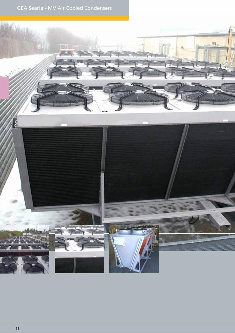
38 39
GEA Searle - MV Air Cooled Condensers

38 39
MV Condensers
The MV range extends the versatility of Searle’s Air cooled condensers into a V-Bank configura-tion with a combination of 3 coil widths and 3 module lengths, 2 fans wide. The available rangehas a duty from 36kW to 1088kW.
GEA Searle achieves a close specification match by offering three module length options of 1200mm, 1440mm or 1800mm across three coil width options in the small footprint V-Bank formation. The MV...M has 2 x 1524mm high coils and the MV...L has 2 x 1905mm high coils with 2 fans wide, both sizes offer the choice of 2 to 8 fans in length. Combined with coil sizes from 2 to 4 row coils and multiple standard fan options up to 910mm, this range of V configra-tion units is comprehensive.
GEA Searle offers an EC fan, a highly efficient and very low noise complete control package. Full details of the EC fan and the best-suited application areas are included within this cata-logue. Due to the large number of options only a selection of the range is available in this catalogue, selection is best achieved using the condenser data tables or the Searle selection software, either on-line at www.searle.co.uk or via the Searle Selection CD.
Fan data table
0.75 255 0.3 0.5
870 5.7 650 3.3 1.10
3.1 4.3
1.2 350 0.5 0.8
A,B,C 4.3
2.5
360
450
895
665
1
19
2.3
14
6.2
A,B,C
A,B,C
A,B,C
A,B,C
A,B,C
800mm
910mm
Variable100 - 855
N8088 Pole
Q81212 Pole
N9066 Pole
09ECEC Technology
N5044 Pole
N812 12 Pole
Fan type &Pole
Diameter ModuleSpeed (rpm)
Delta
FLC (Amp) SC (Amp)
Star
Speed (rpm) FLC (Amp) SC (Amp)
495 1.3 2.2
685 2.5 4
MV A 2 6 2 M - N8 12 D - AL
Range MVModule size A (1200mm), B (1440mm), C (1800mm)
Fans type N8 (800mm), Q8 (800mm), 09 (910mm), N9 (910mm), 99 (990mm), L9 (990mm)
Power D = Delta, S = Star, 2 = 2 Speed, Variable speed
Coil material AL = Copper tubes/ Aluminium fns, AV = Copper tubes with 2 pack epoxy coated aluminium fns. CU = Copper tubes/ Copper fns, ET = Copper tubes/ Copper fns electro-tinned, Bg = Copper tube/Aluminium fn Blygold coated
Motor speed (poles) 06, 08, 12, or EC
Bank of fans 2Fans per bank 1 - 8
Coils rows 2, 3, 4Coil Orientation M = Medium, L = Large
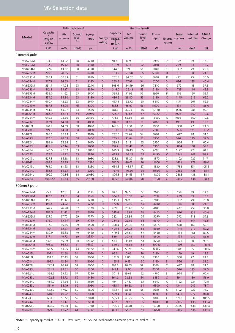
40 41
MV Selection data
800mm 6 pole
910mm 6 pole
MVA212M 104.3 14.02 58 4230 E 91.5 10.9 51 2950 D 159 39 12.3 MVC212M 132.5 15.42 58 3930 D 115.9 12.3 52 2810 D 239 53 16.7 MVB214M 177.6 13.27 58 4390 D 144.8 9.93 51 3040 C 382 79 25.0 MVA222M 209.8 28.05 61 8470 E 183.9 21.98 55 5900 D 318 68 21.5
MVC222M 266.1 30.83 61 7870 D 232.6 24.62 54 5630 D 477 95 30.0 MVA224M 317.5 24.55 61 9160 D 255.6 17.97 54 6200 D 636 128 40.4
MVB232M 351.4 44.28 63 12240 E 308.6 34.99 56 7210 D 572 118 37.3 MVA233M 412.2 39.17 63 13320 D 346.0 29.43 55 9150 D 715 144 45.5 MVB233M 458.0 41.62 63 12800 D 388.8 31.98 55 8950 D 858 168 53.1 MVB234M 534.2 39.80 63 13180 D 436.2 29.80 55 9130 C 1145 219 69.2
MVC234M 600.4 42.52 62 12610 C 493.3 32.72 55 8880 C 1431 261 82.5
MVC243M 687.5 58.75 63 16390 D 585.5 46.02 56 11600 C 1431 272 86.0
MVB244M 714.3 53.07 63 17580 D 581.3 39.73 56 12170 C 1526 285 90.1 MVB254M 886.9 66.34 64 21980 D 726.9 49.66 57 15220 C 1908 350 110.6 MVA264M 949.5 73.66 66 27480 D 771.8 53.93 58 18600 D 1908 350 110.6
MVA212L 117.9 14.90 58 4050 E 104.7 11.80 51 2860 D 199 49 15.5 MVB213L 170.9 14.69 58 4090 D 145.8 11.50 51 2900 C 358 77 24.3 MVC214L 219.2 14.88 58 4050 C 183.8 11.66 51 2880 C 596 121 38.2
MVB222L 265.6 30.83 61 7870 D 232.6 24.62 54 5630 D 477 98 31.0 MVA223L 312.6 28.09 60 8460 D 265.1 21.64 52 5930 D 596 125 39.5 MVB224L 398.6 28.34 61 8410 C 329.8 21.81 53 5920 C 954 191 60.4 MVA233L 471.1 42.14 63 12690 D 397.7 32.47 55 8900 D 894 180 56.9 MVA234L 546.5 40.32 63 13080 D 446.3 30.43 55 9090 C 1192 224 70.8
MVC233L 573.3 45.92 63 11890 C 489.1 36.43 56 8490 C 1341 249 78.7
MVA243L 627.3 56.18 63 16930 D 528.8 43.29 56 11870 D 1192 227 71.7 MVB243L 692.3 58.75 63 16390 D 586.5 46.02 56 11600 C 1431 272 86.0
MVC243L 762.0 61.23 63 15850 C 654.5 48.57 57 11330 C 1788 334 105.5
MVC244L 881.1 59.53 63 16230 C 737.6 46.66 56 11530 C 2385 438 138.4 MVB254L 999.7 70.86 64 21030 C 826.3 54.53 57 14800 C 2385 438 138.4
MVA264L 1088.52 80.63 65 26160 D 895.6 60.86 58 18190 C 2385 438 138.4
MVA212M MVC212M MVB214M MVA222M
MVC222M MVA224M
MVB232M
MVA233M
MVB233M MVB234M
MVC234M MVC243M
MVB244M MVB254M
MVA264M
MVA212L 107.4 12.68 54 3050 D 95.3 10.06 50 2110 C 199 49 15.5 MVB213L 152.2 12.43 54 3080 C 131.9 9.86 50 2120 C 358 77 24.3
MVC214L 195.1 12.54 54 3060 C 165.2 9.93 50 2120 B 596 121 38.2 MVB222L 242.4 26.20 57 6000 D 209.2 20.63 52 4180 C 477 98 31.0 MVA223L 281.5 23.81 56 6300 D 243.1 19.05 51 4300 C 596 125 39.5
MVB224L 354.6 23.92 57 6280 C 301.8 19.08 52 4300 B 954 191 60.4
MVA233L 422.5 35.72 59 9450 D 364.3 28.58 54 6450 C 894 180 56.9 MVA234L 489.0 34.36 59 9650 C 414.1 27.37 53 6540 C 1192 224 70.8 MVC233L 511.0 38.79 59 9050 C 435.4 30.58 54 6300 C 1341 249 78.7
MVA243L 562.2 47.62 60 12600 D 483.7 38.11 55 8610 C 1192 227 71.7
MVB243L 618.8 49.72 59 12330 C 529.4 39.46 55 8500 C 1431 272 86.0 MVC243L 683.0 51.72 59 12070 C 585.1 40.77 55 8400 C 1788 334 105.5 MVC244L 783.5 50.17 59 12260 C 662.6 39.73 55 8480 B 2385 438 138.4 MVB254L 888.7 59.80 60 15710 C 755.9 47.70 56 10750 B 2385 438 138.4 MVA264L 979.2 68.72 61 19310 C 833.8 54.73 56 13090 C 2385 438 138.4
9.6595.7 12.1 50 D214084.954 D 159 39 12.3313010.32120.9 13.10 49 C2092104.354 D 239 53 16.731609.01159.3 11.32 48 C2180135.354 C 382 79 25.0323019.30192.4 24.02 53 D4280170.657 D 318 68 21.56270
29.99321.2 37.75 55 C5290282.159 D 572 118 37.37670
22.05373.7 33.64 53 D6570284.259 D 715 144 45.59750
28.32412.9 35.35 54 C64.70358.459 D 858 168 53.1950027.03480.1 33.97 53 C6560408.359 C 1145 219 69.29710
28.62530.9 35.88 54 C6450449.559 C 1431 261 82.5942039.46617.1 49.72 55 C8500530.159 C 1431 272 86.012330
36.04640.1 45.29 54 C8750543.160 C 1526 285 90.11295045.05798.8 56.62 55 C10940680.9
62C 1908 350 110.616180
16.97288.3 21.42 51 C4410245.457 D 636 128 40.46650
20.63242.7 26.20 53 C4180209.157 D 477 95 30.06320
866.5 64.25
6119970 D 743.6 50.92 55 13250 C 1908 350 110.6
Delta (High speed) Star (Low Speed)
Model
Capacity*
R404A&
R507A
kW Wm3/s dB(A)
Airvolume
Soundlevel**
Powerinput Energy
rating
kW Wm3/s dB(A)
Total surface
R404A Charge
Internalvolume
m2 dm3 kg
Airvolume
Powerinput Energy
rating
Capacity*
Soundlevel **
R404A&
R507A
Note: * Capacity quoted at 15 K DT1 Dew Point, ** Sound level quoted as mean pressure level at 10m

40 41
800mm 8 pole
800mm 12 pole
MVC212M 101.8 9.90 46 1500 C 87.3 7.62 40 950 B 239 53 16.7
MVB214M 129.0 8.44 48 1600 B 106.3 6.44 41 1020 B 382 79 25.0MVA222M 166.0 18.40 50 3160 C 140.3 14.05 43 1980 B 318 68 21.5MVC222M 204.0 19.81 49 3010 C 174.3 15.24 43 1910 B 477 95 30MVA224M 231.5 15.69 51 3310 C 189.8 11.97 44 2080 B 636 128 40.4
MVB232M 274.5 28.68 51 3870 B 234.2 21.96 45 2440 B 572 118 37.3MVA233M 311.3 25.16 53 4830 C 259.4 19.26 45 3070 B 715 144 45.5
MVB233M 345.1 26.78 52 4770 B 288.0 20.38 45 3000 B 858 168 53.1
MVB234M 389.2 25.31 53 4820 B 320.0 19.33 45 3060 B 1145 219 69.2MVC234M 432.3 27.13 52 4750 B 353.0 20.60 45 2990 A 1431 261 82.5MVC243M 514.1 37.64 52 6260 B 430.0 28.71 45 3930 B 1431 272 86.0MVB244M 517.4 33.75 54 6430 B 424.9 25.77 46 4080 B 1526 285 90.1MVB254M 649.5 42.19 54 8040 B 535.2 32.21 47 5110 B 1908 350 110.6
MVA264M 702.9 47.08 55 9950 B 578.8 35.91 48 6240 B 1908 350 110.6MVA212L 92.9 9.63 47 1540 C 79.3 7.38 40 970 B 199 49 15.5
MVB213L 127.9 9.41 47 1560 B 107.0 7.18 40 980 B 358 77 24.3MVC214L 159.6 9.48 47 1550 B 131.4 7.23 40 970 A 596 121 38.2MVB222L 204.2 19.81 49 3010 C 174.8 15.24 43 1910 B 477 98 31.0MVA223L 234.7 18.08 49 3170 B 195.5 13.75 42 1990 B 596 125 39.5MVA224L 264.3 17.11 50 3200 B 216.9 13.05 42 2030 B 795 164 51.8MVA233L 351.4 27.12 52 4760 B 292.0 20.62 45 2990 B 894 180 56.9MVA234L 395.0 25.66 53 4810 B 324.1 19.58 45 3050 B 1192 224 70.8MVC233L 423.1 29.31 51 4560 B 352.9 22.46 44 2890 A 1341 249 78.7MVA243L 466.4 36.16 53 6340 B 387.3 27.49 46 3980 B 1192 227 71.7MVB243L 513.0 37.64 52 6260 B 427.2 28.71 45 3930 B 1431 272 86.0MVC243L 568.9 39.08 52 6080 B 475.9 29.95 45 3860 A 1788 334 105.5MVC244L 640.1 37.92 52 6220 B 523.9 28.93 45 3910 A 2385 438 138.4
MVB254L 727.3 45.22 54 7930 B 594.6 34.33 46 4980 A 2385 438 138.4MVA264L 796.2 51.32 55 9620 B 655.4 39.16 48 6100 B 2385 438 138.4
MVC212M 75.2 6.01 35 600 A 67.0 4.89 29 330 A 239 53 16.7MVB214M 88.0 5.06 35 620 A 76.0 4.12 29 350 A 382 79 25.0MVA222M 121.4 11.12 38 1220 B 108.5 9.07 32 680 A 318 68 21.5MVC222M 150.8 12.02 38 1200 A 134.3 9.79 32 660 A 477 95 30.0MVA224M 160.0 9.48 38 1270 A 138.2 7.67 32 740 A 636 128 40.4MVB232M 201.8 17.38 40 1510 A 180.4 14.23 34 840 A 572 118 37.3
MVA233M 219.8 15.17 40 1860 A 192.7 12.35 34 1060 A 715 144 45.5MVB233M 242.4 16.06 39 1840 A 213.5 13.15 34 1040 A 858 168 53.1MVB234M 264.9 15.17 40 1860 A 228.5 12.36 34 1060 A 1145 219 69.2MVC234M 295.1 16.29 39 1830 A 251.6 13.15 34 1040 A 1431 261 82.5
MVB244M 353.3 20.22 41 2480 A 304.7 16.47 35 1420 A 1526 285 90.1MVC243M 361.9 22.74 40 2430 A 314.8 18.46 34 1360 A 1431 272 86.0MVB254M 439.7 25.28 42 3100 A 380.6 20.59 35 1770 A 1908 350 111.0MVA264M 477.8 28.44 43 3810 A 413.7 23.02 36 2230 A 1908 350 111.0
MVA212L 68.3 5.83 35 600 A 61.2 4.78 29 330 A 199 49 15.5MVB213L 90.2 5.69 35 600 A 78.5 4.61 29 340 A 358 77 24.3MVC214L 107.1 5.69 35 600 A 92.8 4.61 29 340 A 596 121 38.2
MVB222L 150.7 12.02 38 1200 A 134.2 9.79 32 660 A 477 98 31.0MVA223L 165.0 10.84 37 1220 A 144.8 8.87 31 690 A 596 125 40.0MVB224L 196.7 10.86 37 1220 A 167.8 8.76 32 690 A 954 191 60.4
MVA233L 247.3 16.26 39 1830 A 217.8 13.30 34 1030 A 894 180 57.0MVA234L 270.3 15.38 40 1850 A 232.9 12.51 34 1050 A 1192 224 70.8
MVC233L 298.2 17.68 40 1810 A 258.6 14.36 34 1010 A 1341 249 79.0MVA243L 330.5 21.67 40 2450 A 290.0 17.73 35 1380 A 1192 227 72.0
MVB243L 362.5 22.74 40 2430 A 315.9 18.46 34 1360 A 1431 272 86.0MVC243L 396.9 23.57 40 2420 A 344.1 19.15 34 1340 A 1788 334 106.0MVC244L 429.4 22.75 40 2430 A 371.4 18.42 34 1360 A 2385 438 138.4MVB254L 491.6 27.16 41 3060 A 420.4 21.91 35 1730 A 2385 438 138.4
MVA264L 541.1 30.76 42 3700 A 465.8 25.03 36 2110 A 2385 438 138.4
MVA212M 60.0 5.56 35 610 B 54.0 4.54 29 340 A 159 39 12.3
MVA212M 82.7 9.20 47 1580 C 70.0 7.03 40 990 B 159 39 12.3
Delta (High speed) Star (Low Speed)
Model
Capacity*
R404A&
R507A
kW Wm3/s dB(A)
Airvolume
Soundlevel**
Powerinput Energy
rating
kW Wm3/s dB(A)
Total surface
R404A Charge
Internalvolume
m2 dm3 kg
Airvolume
Powerinput Energy
rating
Capacity*
Soundlevel **
R404A&
R507A
Note: * Capacity quoted at 15 K DT1 Dew Point, ** Sound level quoted as mean pressure level at 10m

IndividualFan Isolators
(optional)
225 70
1919Fixing Ctrs
42 43
MV...M Model drawings
MV (M)
282
2234 Overall casework
CommonJ/Box
1882 Lifting Ctrs
2091
Max
O/A
ll
1809
To
F/D
eck
2250 O/All Forklift channel
180.7 350 1188.6 350 180.7
225 2403
2340 Lifting Ctrs
70
IndividualFan Isolators
(optional)
Hot gas inlet
Liquid outlet
1440
Forklift Ctrs2365 Fixing Ctrs19 19
B1
Fixing Ctrs
B2
Fixing Ctrs
B1
Fixing Ctrs
C

282.
0
42 43
MV...L Model drawings
MV (L)
2340.0 L IFTING CTR S
282.
0
928 . 0
225 70
2340 Lifting Ctrs
2403
IndividualFan Isolators
(optional)
Hot Gas in
Liquid out
15.0 Fixings HolesIn base of legs
Reference dims shown
19 19
144
Forklift Ctrs
2365 Fixing Ctrs
2234 Overall casework
1886 Lifting CtrsCommonJ/Box
282
311350928350311
2250 O/All Forklift channel
2449
Max
O/A
ll
2167
To
F/D
eck
IndividualFan Isolators
(optional)
225 70
1919Fixing Ctrs
B1
Fixing Ctrs
B2
Fixing Ctrs
B1
Fixing Ctrs
C
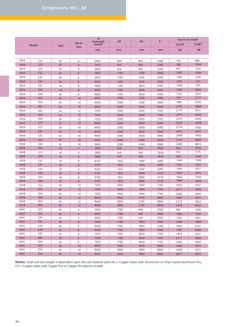
44 45
Dimensions MV...M
Model
Approx dry weight
AL/AV CU/ET
MVA 222223
224
232
233
234
242
243
244
252
253
254
262
263264272
273
274
232
233
234222
223224
232
233
234
242
243244
252
MVA
MVA
MVA
MVA
MVA
MVA
MVA
MVAMVA
MVA
MVA
MVA
MVA
MVA
MVA
MVA
MVA
MVA
MVA
MVA
MVB
MVBMVB
MVB
MVB
MVB
MVB
MVBMVB
MVB
B2
mm mm
C
mm
B1
mm
ACasework
overall
MM
M
M
M
M
M
M
MM
M
M
M
M
MM
M
M
M
M
M
MM
M
M
MM
M
M
M
Size
M
44
6
4
6
6
8
8
108
10
10
12
12
1412
8
8
6
6
6
44
4
16
16
16
14
14
8
No of fans
10
kg kg
253MVB M 10
254262263264MVB
222MVC
223224
232
233234242
243244252253
254MVC M 10
MVC M 10
MVC M 10
MVC M 8
MVC M 8
MVC M 8
MVC M 6
MVC M 6
MVC M 6
MVC M 4
MVC M 4
M 4
M 12
MVB M 12
MVB M 12
MVB
N/AN/A
1200
1200N/A
12002400
12002400
2400
1200
1200
24002400
2400
2400
2400
3400
34002400
3400N/A
1440
N/AN/A
1440
1440
2880
2880
28801400
1400
2720
N/A
1840
1840184036003600
360018001800
1800
N/AN/A
272027201400
23652365
3565
35652365
35654765
59654765
4765
5965
5965
71657165
7165
8365
8365
9565
95658365
95652845
4285
28452845
4285
4285
5725
5725
57257165
7165
3565
8965
8965896571657165
716553655365
5365
35653565
8602860286027165
N/AN/A
1183
1183N/A
11831183
23831183
1183
2383
2383
23832383
2383
2382
2382
2382
23822382
2382N/A
1422
N/AN/A
1422
1422
1422
1422
14222862
2862
1782
3565
3565356517821782
178217821782
1782
17821782
2862286228622862
24032403
3603
36032403
36034803
60034803
4803
6003
6003
72037203
7203
8403
8403
9603
96038403
96032883
4323
28832883
4323
4323
5763
5763
57637203
7203
9003
9003900372037203
720354035403
5403
36033603
3603
8640864086407203M 10
720788
1189
1087857
12921449
18111722
1585
1981
2152
25352377
2173
2535
2774
3170
28983013
830912
1367
1244994
1490
1659
18231986
3443
2073
2277
2977
3545246623822177
197317871633
1480
11921089
987
2978273324872482
8661008
1518
13061149
17311741
21772307
2024
2530
2884
34603036
2612
3048
3542
4049
34834037
10051175
1762
15081345
2017
2010
2689
2350
4614
2512
2936
4075
2721301532602836
241224452127
1809
16311418
1206
4032352330153360
Notes: Total unit dry weight is dependent upon the coil material used (AL = Copper tubes with Aluminium or Vinyl coated aluminium fins, CU = Copper tubes with Copper fins or Copper fins electro-tinned).
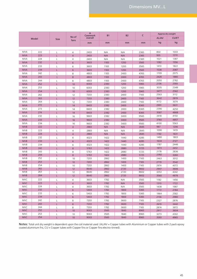
44 45
MVA 222223
224
232
233
234
242
243
244
252
253
254
262
263264272
273
274
232
233
234222
223224
232
233
234
242
243244252
MVA
MVA
MVA
MVA
MVA
MVA
MVA
MVAMVA
MVA
MVA
MVA
MVA
MVA
MVA
MVA
MVA
MVA
MVA
MVA
MVB
MVBMVB
MVB
MVB
MVB
MVB
MVBMVBMVB
LL
L
L
L
L
L
L
LL
L
L
L
L
LL
L
L
L
L
L
LL
L
L
LL
L
L
LL
44
6
4
6
6
8
8
108
10
10
12
12
1412
8
8
6
6
6
44
4
16
16
16
14
14
810
253MVB L 10254262263
264MVB
222MVC L 4223224232
233234
242
243244252
253254MVC L 10
MVC L 10
MVC L 10MVC L 8
MVC L 8
MVC L 8
MVC L 6
MVC L 6
MVC L 6
MVC L 4
MVC L 4
L 12
MVB L 12
MVB L 12
MVB
N/AN/A
1200
1200N/A
12002400
12002400
2400
1200
1200
24002400
2400
2400
2400
3400
34002400
3400N/A
1440
N/AN/A
1440
1440
2880
2880
28801400
1400
2720
N/A
18401840
184036003600
3600
18001800
1800N/AN/A
272027201400
23652365
3565
35652365
35654765
59654765
4765
5965
5965
71657165
7165
8365
8365
9565
95658365
95652845
4285
28452845
4285
4285
5725
5725
57257165
7165
3565
8602
89658965
896571657165
7165
53655365
536535653565
860286027165
N/AN/A
1183
1183N/A
11831183
23831183
1183
2383
2383
23832383
2383
2382
2382
2382
23822382
2382N/A
1422
N/AN/A
1422
1422
1422
1422
14222862
2862
1782
2862
35653565
356517821782
1782
17821782
178217821782
286228622862
24032403
3603
36032403
36034803
60034803
4803
6003
6003
72037203
7203
8403
8403
9603
96038403
96032883
4323
28832883
4323
4323
5763
5763
57637203
7203
3603
90039003
900372037203
7203
54035403
540336033603
8640
864086407203L 10
850935
1410
12821021
15381709
21362050
2428
3035
3477
41723642
2563
2991
2390
3760
34183587
9871090
1634
14801192
1787
1973
21782382
4100
2463
2719
1182
35933273
291728742619
2327
21561964
177214381310
3560
325329472974
10331210
1822
15561387
20872075
25932782
1880
2349
2562
30742819
3112
3631
4250
4857
41504868
12061419
2127
18031631
2446
2412
3260
2836
5563
3012
3542
1456
49654302
360439723442
2876
29802582
218419871722
4878
424236064072
Notes: Total unit dry weight is dependent upon the coil material used (AL/AV = Copper tubes with Aluminium or Copper tubes with 2 pack epoxy coated aluminium fns, CU = Copper tubes with Copper fins or Copper fins electro-tinned).
Model
Approx dry weight
AL/AV CU/ETB2
mm mm
C
mm
B1
mm
ACasework
overallSizeNo of fans
kg kg
Dimensions MV...L

GEA Searle - Gas Coolers
GEA Searle have embraced the re-emergence of Carbon Dioxide as a refriger-ant having worked on many customer collaboration type development projects dating back to 1997. As the technology has developed and the boundaries have been tested and pushed GEA Searle have embraced the opportunities to develop bespoke solutions with the long term view of standardising products for the mass market once the refrigerant and various system designs have been adopted.
46 47

Control Options
There are various optional GEA Searle control packages available, includ-ing vari-able speed controlled products using Searle inverter control or the latest EC fan control system. The control options include: EC speed control Inverter speed control, Triac speed control, Dual speed step control, Single speed step control. If a speed control method is utilised, Searle recom- mends adding the option of internal motor protection.
Blygold® Coating
GEA Searle’s specialist coating facility, where a Blygold® coating is applied and cured to protect the fnned coils against harsh environmental condi-tions such as erosion by sand or salt. It provides a barrier and avoids the risk of electrolytic reactions between the two metals involved. The coating contains aluminium, in order to maintain the thermal performance of the coil, resulting in an extension of the lifetime, maximum cooling capacity and reduction of energy costs. The coating is oriented in such a way that it creates a very high chemical resistance at low layer thickness.
Noise Data
The mean unit sound pressure data at 10m is given for each model in the cata-logue and is certified as part of the Eurovent scheme. Sound power testing and sound pressure calculation are carried out in accordance with EN13487. Mean sound pressure levels are for a parallel piped surface surrounding the unit on a reflective plane. Power levels and sound spectrum are available on request.
Gas Cooler Features
Standard ranges of Gas coolers : ME, MG, MM, MX and MV
Maximum heat exchanger length of 7200mm
Fan sizes from 500mm to 990mm
Speeds from 12 up to 4 pole, with EC variable speed drives
Trans-critical gas cooler in high ambient conditions
Sub-critical condenser in low ambient conditions
Designed with a maximum operating pressure of 120BarG
The fin pack is split to ensure the structural stability of the heat exchanger over a long service life
Copper tubes brazed in to T304L stainless steel headers for longer product life expectancy
46 47

48 49
120 Bar Gas Coolers
Mo
del
s
Euro
ven
t
ME
MVM
MX
MVL
MM
MG
Mo
del
s
ME
Range benefits
Meeting your specification - Our range has literally 1000s of models, created through a modular design and a variety of fan sizes, offering a greater choice to match your requirements.
Designed to be quiet - Our gas coolers can meet even the most stringent noise restrictions using the latest 4 , 6, 8 & 12 pole fansets. In addition, we offer EC technology across the standard range which offers variable speed control and high efficiency.
Backing our beliefs - We offer two years warranty on all gas coolers and an additional one year warranty on all ebmpapst fans from dispatch (subject to our standard Terms & Conditions of Sale and excluding corrosion through misapplication).
Fansets
The fansets chosen for the range offer the best combined performance for air volume, noise and efficiency available in the refrigeration industry, customers can select the latest EC technology, offering high efficiency and speed controllability.
Coils
Coils are manufactured from high-quality materials ensuring a quality product without com-promise. These coils have been tested extensively in Searle’s Research & Development facility to ensure performance.
Standard coils are manufactured from copper tubes, which are mechanically expanded into fully collared holes in the fins. This ensures an effective and permanent bond between the tube and the fin, maximising heat transfer characteristics.
Within the coil casework surround, each fan chamber is separated by internal baffle plates to prevent windmilling of off-cycle fans. Alternative fin materials are available to give added protection in polluted or saline atmospheres: -
Cu/Av - Copper tube / vinyl coated aluminium fins Cu/Cu - Copper tubes / copper fins Cu/Et - Copper tubes / electro tinned copper fins Cu/Al/Bg- Copper tubes / aluminium fins Blygold coated
All standard coils are fully leak and strength tested to 36 bar for a maximum operating pressure of 27 bar.

48 49
No
. Fan
s
1 - 8
Ro
ws
of
Fan
s
Sup
ply
EC F
ans
Ad
iab
atic
Co
olin
gSy
stem
Fin
Mat
eria
ls
Options
2 - 16 2 3ph
AIAvCuEtBg
1 - 8 1 3ph
2 - 16 2 3ph
AIAvCuEtBg
AIAvCuEtBg
1 - 8 1 3ph
AIAvCuEtBg
1 - 16 3ph1 or2
AIAvCuEtBg
1 &3ph
1 or2
AIAvCuEtBg
1 - 8
No
. Fan
s

GEA Searle - MV Air Cooled Condensers
50 51
GEA Searle - Gas Coolers

Gas Coolers
GEA Searle offer a range of gas coolers based upon the standard ranges ME, MG, MM, MX and MV with a maximum heat exchanger length of 7200mm. All ranges have optimised heat exchangers to suit the properties of Carbon Dioxide and are designed to suit the design condi-tions specified. The ranges offer fan sizes from 500mm to 990mm with speeds from 12 up to 4 pole, with EC variable speed drives for many.
Most gas cooler designs are optimised to suit the dual operation expectations i.e. trans-critical gas cooler in high ambient conditions, sub-critical condenser in low ambient conditions.
Whilst the temperatures and pressures involved for trans-critical operation are high, the cool-ing process being single phase is relatively simple and with over 80 years of experience in the design and manufacture of standard and bespoke heat exchangers GEA Searle offer the con-fidence and quality expected.
The gas coolers have been designed with a maximum operating pressure of 120BarG. The coils are pneumatically leak and strength tested to avoid internal contamination. Due to the high discharge temperatures at the start of the cooling process, GEA Searle split the fin pack to ensure the structural stability of the heat exchanger over a long service life.
GEA Searle has tested many material combinations and have standardised on copper tubes brazed in to T304L stainless steel headers to ensure long product life expectancy without the need for regular paint applications. To keep the heat exchangers in lower PED categories GEA Searle split the coils into multiple sections limiting header sizes .
PG A 2 6 2 M - N8 12 D - AL
Range PGModule size A (1200mm), B (1440mm), C (1800mm)
Fans type N8 (800mm), Q8 (800mm), 09 (910mm), N9 (910mm), 99 (990mm), L9 (990mm)
Power D = Delta, S = Star, 2 = 2 Speed, Variable speed
Coil material AL = Copper tubes/ Aluminium fns, AV = Copper tubes with 2 pack epoxy coated aluminium fns. CU = Copper tubes/ Copper fns, ET = Copper tubes/ Copper fns electro-tinned, Bg = Copper tube/Aluminium fn Blygold coated
Motor speed (poles) 06, 08, 12, or EC
Bank of fans 2Fans per bank 1 - 8
Coils rows 2, 3, 4Coil Orientation M = Medium, L = Large
50 51

GEA Searle range of dry air coolers is a modular design of flat-bed and V-bank units arranged in single and double bank configura-tions with multiple module lengths. The new range builds on theexpertise gained from many years at the forefront of dry air cooler technology resulting in the most extensive range of Dry Air Cool-ers created by GEA Searle. The range of GEA Searle dry air cooler combinations enable the closest possible matching to a required specification taking into consideration duty, cost, noise level, size and efficiency (duty/ motor input power).
52 53
GEA Searle - Dry Air Coolers

Control Options
There are various optional GEA Searle control packages available, includ-ing vari-able speed controlled products using Searle inverter control or the latest EC fan control system. The control options include: EC speed control Inverter speed control, Triac speed control, Dual speed step control, Single speed step control. If a speed control method is utilised, Searle recom- mends adding the option of internal motor protection.
Other Options
GEA Searle offers a wide range of accessories and additional options, in-cluding: anti-vibration mounts and leg extensions - to enhance air fow in diffcult loca-tions and Adiabatic cooling System (Please see GEA Searle’s Adiabatic Section for further details or contact your GEA Searle representa-tive).
Vertical Mounting
Units maybe specifed as horizontal (standard) or vertical orientation.
Blygold® Coating
GEA Searle’s specialist coating facility, where a Blygold® coating is applied and cured to protect the fnned coils against harsh environmental condi-tions such as erosion by sand or salt. It provides a barrier and avoids the risk of electrolytic reactions between the two metals involved. The coating contains aluminium, in order to maintain the thermal performance of the coil, resulting in an extension of the lifetime, maximum cooling capacity and reduction of energy costs. The coating is oriented in such a way that it creates a very high chemical resistance at low layer thickness.
The Blygold® concept is a revolutionary product created to prevent corro-sion which will ultimately reduce enery costs.
Energy Labelling
Energy Labelling is now part of the Eurovent Certify-All scheme. Rating is based on the ratio of nominal duty to power input with banding as in the table below:
Where R= Nominal Capacity Total fan power input
Noise Data
The mean unit sound pressure data at 10m is given for each model in the catalogue and is certified as part of the Eurovent scheme. Sound power testing and sound pressure calculation are carried out in accordance with EN13487. Mean sound pressure levels are for a parallel piped surface surrounding the unit on a reflective plane. Power levels and sound spectrum are available on request.
52 53
Low 5<R<70
Medium 30<R<45
Hight <30
Extremely low R>110
Very low 70<R<110
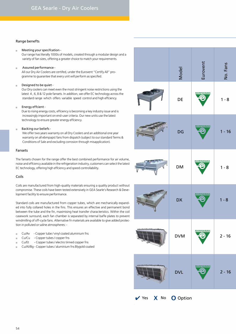
54 55
GEA Searle - Dry Air Coolers
Mo
del
Euro
ven
t
No
. Fan
s
DVL 2 - 16
DVM 2 - 16
DM 1 - 8
DG 1 - 16
DE 1 - 8
DX 1 - 8
Range benefts
Meeting your specifcation - Our range has literally 1000s of models, created through a modular design and a variety of fan sizes, offering a greater choice to match your requirements.
Assured performance - All our Dry Air Coolers are certifed, under the Eurovent “Certify All” pro- gramme to guarantee that every unit will perform as specifed.
Designed to be quiet - Our Dry coolers can meet even the most stringent noise restrictions using the latest 4 , 6, 8 & 12 pole fansets. In addition, we offer EC technology across the standard range which offers variable speed control and high effciency.
Energy effcient - Due to rising energy costs, effciency is becoming a key industry issue and is increasingly important on end-user criteria. Our new units use the latest technology to ensure greater energy effciency.
Backing our beliefs - We offer two years warranty on all Dry Coolers and an additional one year warranty on all ebmpapst fans from dispatch (subject to our standard Terms & Conditions of Sale and excluding corrosion through misapplication).
Fansets
The fansets chosen for the range offer the best combined performance for air volume, noise and effciency available in the refrigeration industry, customers can select the latest EC technology, offering high effciency and speed controllability.
Coils
Coils are manufactured from high-quality materials ensuring a quality product without compromise. These coils have been tested extensively in GEA Searle’s Research & Deve-lopment facility to ensure performance.
Standard coils are manufactured from copper tubes, which are mechanically expand-ed into fully collared holes in the fins. This ensures an effective and permanent bond between the tube and the fin, maximising heat transfer characteristics. Within the coil casework surround, each fan chamber is separated by internal baffe plates to prevent windmilling of off-cycle fans. Alternative fn materials are available to give added protec-tion in polluted or saline atmospheres: -
Cu/Av - Copper tube / vinyl coated aluminium fns Cu/Cu - Copper tubes / copper fns Cu/Et - Copper tubes / electro tinned copper fns Cu/Al/Bg - Copper tubes / aluminium fns Blygold coated
No OptionYes
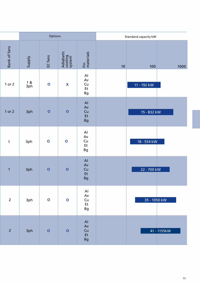
54 55
10 100 1000Ban
k o
f fa
ns
Sup
ply
EC f
ans
Ad
iab
atic
co
olin
gsy
stem
Fin
mat
eria
ls
Standard capacity kWOptions
2 3ph
AIAvCuEtBg
41 - 1155kW
2 3ph
AIAvCuEt Bg
35 - 1050 kW
18 - 554 kW
AIAvCuEtBg
3ph1
3ph
AIAvCuEtBg
15 - 832 kW1 or 2
1 &3ph
AIAvCuEtBg
11 - 192 kW1 or 2
1 3ph
AIAvCuEtBg
22 - 700 kW
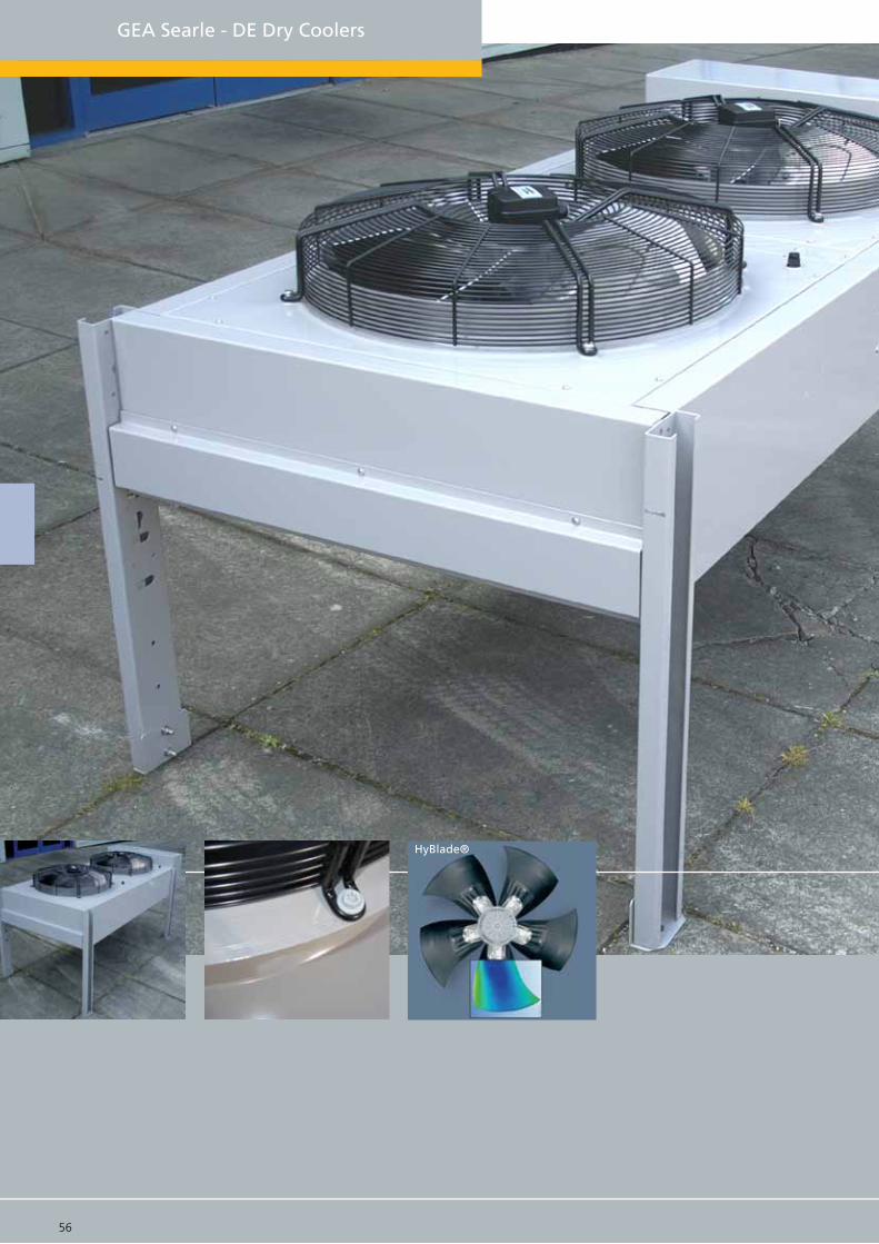
HyBlade®
56 57
GEA Searle - DE Dry Coolers

DE Dry Cooler
The DE range of dry air coolers is based uponthe well established E fin heat exchange matrix, combined with the HyBlade® range of fans from ebmpapst. This combination offers a versatile and economical solution to many refrigeration and air conditioning applications. The range consists of one to eight fans in three coil depths and modules with 500 and 630 mm 4, 6 and 8 pole fans. This results in a wide range of capacities, noise levels and footprints to meet the diverse requirements of the industry.
Optional extras for the DE range include vertical orientation (1 to 4 fan), multi circuiting, alter-native fin materials and coating. Control options include fan cycling, variable speed (including EC) and individual fan isolators. The model selections can be made by using the popular Searle selection software available on CD, as a download from the website or interactively on-line at www.searle.co.uk.
DE Features
3 Module sizes (A,B,C), 500mm or 630mm HyBlade® fansets, 4,6,8 pole or EC, Optional coil fin materials and coating, Powder coated robust casework, Factory fitted or separate control options, Compact design Vertical coil (1-4 fans) or Horizontal coil (1-8 fans), Wall mounting kits available for Vertical coil 1-4 fan units
Fan data table
DE A 1 2 4 H - N6 04 3 - AL
Range DEModule size A, B, C
Fans type N5 = 500mm,N6 = 630mm
Power 1 = 1 - phase, 3 = 3 - phase
Coil material AL = Copper tubes/ Aluminium fns, AV = Copper tubes with 2 pack epoxy coated aluminium fns. CU = Copper tubes/ Copper fns, ET = Copper tubes/ Copper fns electro-tinned, Bg = Copper tube/Aluminium fn Blygold coated
Motor speed (poles) 04, 06, 08, EC = Speed control, XX = Less fansets
A,B
B,C 5 1035 3.1 14
900 1.8 700 1.1 1.7
1 1.9 440 0.5 0.6
0.4 560 0.2 0.3
A,B 2.8
A,B 1.2
1330
680
1225
915
20
5.4
1
4.7
2.3
B,C
B,C
500mm
630mm
640
N5066 Pole
N6044 Pole
N6066 Pole
N6088 Pole
N5044 Pole
N5088 Pole
Fan type &Pole
Diameter ModuleSpeed (rpm)
Delta
FLC (Amp) SC (Amp)
Star
Single Phase
Speed (rpm) FLC (Amp) SC (Amp)
Single phase
Bank of fans 1 or 2Fans per bank 1 - 4
Coils rows 2, 3, 4Coil Orientation H = Horizontal, V = Vertical
56 57

DE Model drawings & Dimensions
58 59
ME Single bank horizontal unit ME Vertical unit
Optional fan isolator
W (Overall legs)
Optional J/box
D Fixing Centres
772 Fixing centres
H (o
vera
ll ca
sew
ork)
ME Double bank horizontal unit
Optional fan isolator
W (Overall legs)
Optional J/box
D Fixing Centres
1fixing hole 11.0mm x 16.5mmin base of each leg
15
800 42.9
1070
363
288
241
515
A
B2
C
B1
38
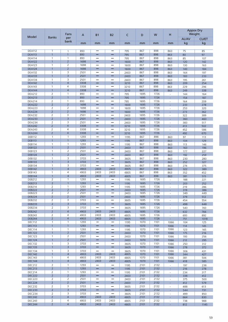
58 59
DEA112DEA113DEA114DEA122DEA123DEA124DEA132DEA133DEA134DEA142DEA143DEA144DEA212DEA213DEA214DEA222DEA223DEA224DEA232DEA233DEA234DEA242DEA243DEA244DEB112DEB113DEB114DEB122DEB123DEB124DEB132DEB133DEB134
DEB212
DEB213DEB214DEB222DEB223DEB224DEB232DEB233DEB234
DEB142DEB143DEB144
DEB242DEB243DEB244DEC112DEC113DEC114DEC122DEC123DEC124DEC132DEC133DEC134
DEC212DEC213DEC214DEC222DEC223DEC224DEC232DEC233DEC234
DEC142DEC143DEC144
DEC242DEC243DEC244
24032403160016001600795795795
480548054805
480548054805
480548054805
480548054805
360536053605240324032403119511951195
360536053605240324032403119511951195
36053605360524032403240311951195
1195
3605360536052403240324031195119511953210321032102403240324031600160016007957957953210321032102403
240324032403
240324032403
240324032403
240324032403
25012501169816981698893893893
490349034903
490349034903
490349034903
490349034903
370337033703250125012501129312931293
370337033703250125012501129312931293
37033703370325012501250112931293
1293
3703370337032501250125011293129312933308330833082501250125011698169816988938938933308330833082501
33222111
444
444
444
444
333222111
333222111
33322211
1
3332221114443332221114443
11111111
111
222
111
222
222222222
111111111
22222222
2
1111111112222222222221111
867867867867867867867867
867867867
169516951695
107010701070
210121012101
210121012101210121012101210121012101
107010701070107010701070107010701070
16951695169516951695169516951695
1695
867867867867867867867867867169516951695169516951695169516951695169516951695867867867867
898898898898898898898898
898898898
172617261726
110111011101
213221322132
213221322132213221322132213221322132
110111011101110111011101110111011101
17261726172617261726172617261726
1726
898898898898898898898898898172617261726172617261726172617261726172617261726898898898898
863863863863863863863863
863863863
---
106610661066
---
---------
106610661066106610661066106610661066
--------
-
863863863863863863863863863
------------
863863863863
183164140130120858075
322352381
632693751
344381418
664738812
499544488412375338234216197
306278250212193175123114104
543498454379349319219203
188
27425223019217716311310497492452413383360322273253233164154144249229209195
240324032403
240324032403
240324032403
240324032403
2331971841631421079785
389452515
7668921018
427506585
8309881145
850731613579500412317278238
431372312295256216165145125
743648554512449386286252
221
375327280259227196146129113670586502517460389362320278209187164338296254261
A
mm
H
mm
W
mm
D
mm
C
mm
B2
mm
B1
mm kg kgAL/AV CU/ET
Model BanksFans per
bank
Appox DryWeight.
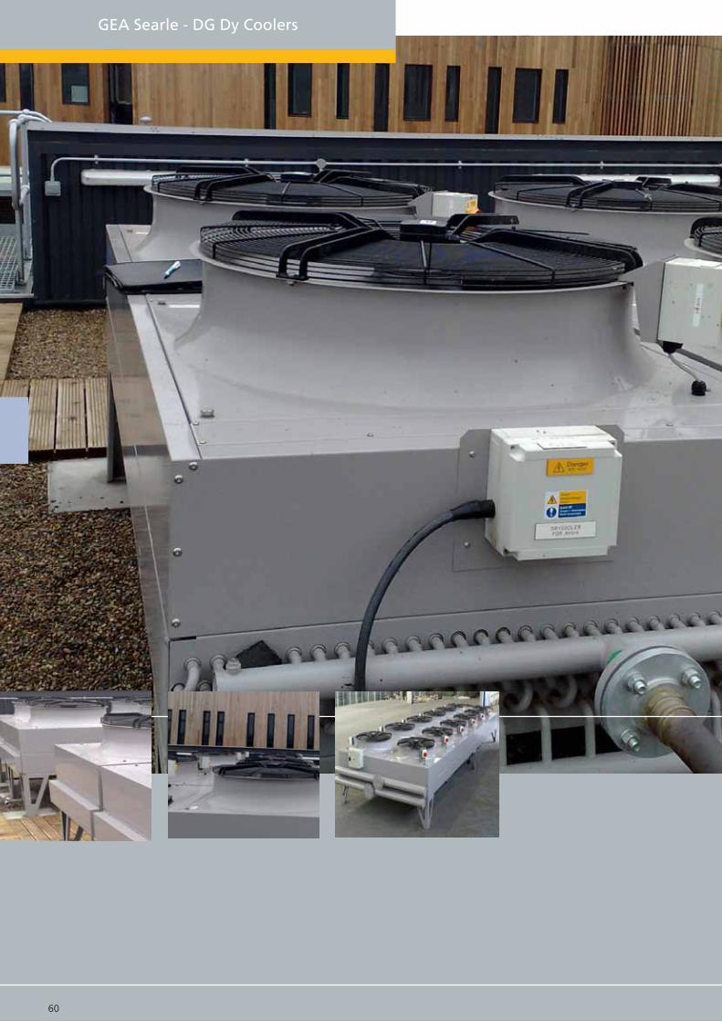
GEA Searle - DG Dy Coolers
60 61

DG Dry Cooler
The DG range of Dry Air Coolers is a comprehensive and versatile range, suitable for a wide variety of applications, with a duty range of 21kW to 617kW. These capacities can be achieved in flat-bed horizontal and vertical configurations. In addition, Searle has created the latest inovation of blow-through horizontal designs for high temperature applications. As with all dry coolers, optimum selection is best achieved using the Searle selection software, either on-line at www.searle.co.uk or via the Searle Selection CD.
GEA Searle achieves a close specification match through module length options of 1200mm, 1440mm and 1800mm in a single (1143mm) or double (2286mm) bank configuration. The range is up to 8 fans in length, combined with coil sizes between 2 to 4 row and multiple stan-dard fan options up to 910mm.
For the ultimate in fan speed control, GEA Searle offers the EC fan, a high efficiency and low noise, complete fan speed control package. For full details of the EC fanset and the suitable applications please refer to the back of this catalouge.
Fan data table
0.75 255 0.3 0.5
870 5.7 650 3.3 1.10
3.1 4.3
1.2 350 0.5 0.8
A,B,C 4.3
2.5
360
450
895
665
1
19
2.3
14
6.2
A,B,C
A,B,C
A,B,C
A,B,C
A,B,C
800mm
910mm
Variable100 - 855
N8088 Pole
Q81212 Pole
N9066 Pole
09ECEC Technology
N5044 Pole
N812 12 Pole
Fan type &Pole
Diameter ModuleSpeed (rpm)
Delta
FLC (Amp) SC (Amp)
Star
Speed (rpm) FLC (Amp) SC (Amp)
495 1.3 2.2
685 2.5 4
DG A 1 6 2 H - N8 12 D - AL
Range DGModule size A (1200mm), B (1440mm), C (1800mm)
Fans type N8 (800mm), Q8 (800mm), 09 (910mm), N9 (910mm)
Power D = Delta, S = Star, 2 = 2 Speed
Coil material AL = Copper tubes/ Aluminium fns, AV = Copper tubes with 2 pack epoxy coated aluminium fns. CU = Copper tubes/ Copper fns, ET = Copper tubes/ Copper fns electro-tinned, Bg = Copper tube/Aluminium fn Blygold coated
Motor speed (poles) 06, 08, 12, 09EC = (Max 855rpm)
Bank of fans 1 or 2Fans per bank 1 - 8 (DGA), 1-6 (DGB), 1-5 (DGC)
Coils rows 2, 3, 4Coil Orientation H = Horizontal, V = Vertical
60 61

62 63
1 fixing hole in baseof each leg 15.0
1 B
ank
2 B
ank
Horizontal unit Vertical unit
Notes: All dimensions in mm. Common junction box will vary in size and position depending on the control option required.
63-05
2301
.0 O/
ALL C
ASEW
ORK
100.
0
25 . 0 25. 0
Optional fanisolator
1078 Fixing centres
Hot Gas
Liquid
CommomJ/Box
1158
Ove
rall
case
wor
k
1200 Fixing centre
Optional fanisolator
Indivdualfan isolator(optional)
4040
500
495
270
2221 Fixing centres
2301 Overall casework
1200 Fixing centres
2301
Ove
rall
case
wor
k
5050100
377 495 270Tranist leg63 - 051
4040
500
495
270
1265
100
50 50
377 495 270
4040
70 215
C
B1 B2
A
1158 Overall casework
1 fixing hole in baseof each leg 15.0
1265
Optional fanisolator
DG Model drawings & Dimensions
B3

62 63
kg kg kg kg
AL ALCU CUmm mm mm mm
CB2B1AModel * 1 Bank * 2 Bank
Total unit dry weightFansper
bankFan
banks
DGA_12
1555 2185
1591 1967
1799 2358
2007 2747
1807 2237
2045 2684
1534 1860
1748 2320
1962 2721
1484 1882
1705 2299
1928 2717
761 972 1377 1851
673 814 1199 1517
659 870 1198 1671
592 750 1064 1420
525 631 931 1170
447 589 816 1131
402 509 727 964
358 430 637 797
251 323 452 608
229 284 406 524206 243 362 441
899 1182 1651 2284
809 1023 1472 1950
1201.6 247 359 456
720 864 1295 1616
728 956 1335 1840
656 828 1191 1573
585 701 1049 1314
551 723 1013 1393
498 627 907 1194444 532 799 992
385 501 705 958
351 438 633 824
314 373 563 691
220.5 279 396 523
184.8 215 324 388
933 1221 1727 2362845 1062 1549 2028756 903 1369 1693
793 1032 1462 1990
719 900 1314 1713
645 768 1164 1434637 837 1182 1605586 731 1063 1383
525 624 944 1160
489 634 899 1216
444 554 811 1050
399
3581
3582
2341
2341
2341
3521
3521
2861
2861
2861
3581
3581
3581
3582
2682
2682
2682
3582
35823582
2862
2862
2862
3582
3582
3582
2982
2982
2982
2382
2382
2382
3541
3542
2341
2341
2341
3521
3521
2821
2821
2821
3541
3541
3541
3542
2642
2642
2642
3542
35423542
2822
2822
2822
3542
3542
3542
2942
2942
2942
23422342
2342
7203
7203
8403
8403
8403
9603
9603
8643
8643
8643
9003
9003
9003
7203
5403
5403
5403
3603
3603
3603
1803
1803
1803
7203
72037203
1443
5763
5763
5763
4323
43234323
2883
2883
2883
1443
1443
7203
7203
7203
6003
6003
6003
48034803
4803
3603
3603
36032403
2403
2403
12031203
120311 or 2
474 721 883
342 440 628 839
314 388 568 727
284 335 508 616
197 248 354 460
183 221 324 405
168 194 294 349
2283 3128
7120
7123
8323
8323
8323
9523
9523
8563
8563
8563
8923
8923
8923
7123
5323
5323
5323
3523
3523
3523
1723
17231723
7123
7123
7123
1363
5683
5683
5683
4243
42434243
2803
2803
2803
1363
1363
7123
7123
7123
5923
5923
5923
47234723
4723
3523
3523
3523
2323
2323
2323
1123
1123
1123
9523352135219603
DGA_13 11 or 2DGA_14 11 or 2
DGA_22 21 or 2
DGA_23 21 or 2
DGA_24 21 or 2
DGA_32 31 or 2
DGA_33 31 or 2DGA_34 31 or 2
DGA_42 41 or 2
DGA_43 41 or 2
DGA_44 41 or 2
DGA_52 51 or 2DGA_53 51 or 2
DGA_54 51 or 2
DGA_62 61 or 2
DGA_63 61 or 2
DGA_64 61 or 2
DGA272 72
DGA273 72
DGA274 72
DGA282 82DGA283 8 2
DGA284 82
DGB_12 11 or 2
DGB_13 11 or 2
DGB_14 11 or 2
DGB_22 21 or 2DGB_23 21 or 2
DGB_24 21 or 2
DGB_32 31 or 2
DGB_33 31 or 2
DGB_34 31 or 2DGB_42 41 or 2
DGB_43 41 or 2
DGB_44 41 or 2
DGB_52 51 or 2
DGB_53 51 or 2
DGB_54 51 or 2
DGB262 62
DGB263 62
DGB264 62DGC_12 11 or 2
DGC_13 11 or 2
DGC_14 11 or 2
DGC_22 21 or 2
DGC_23 21 or 2
DGC_24 21 or 2DGC_32 31 or 2
DGC_33 31 or 2
DGC_34 31 or 2
DGC_42 41 or 2
DGC_43 41 or 2
DGC_44 41 or 2
DGC252 52
DGC253 52
DGC254 52
851 1132
Notes: Total unit dry weight is dependent upon the coil material used (AL/AV = Copper tubes with Aluminium or Copper tubes with 2 pack epoxy coated aluminium fns, CU = Copper tubes with Copper fins or Copper fins electro-tinned).

64 65
GEA Searle - DM/DX Dry Coolers

64 65
DM - DX Dry Cooler
The DM and DX ranges of fully weather-proofed dry coolers feature a new range of coil mod-ule sizes to extend the coil surface to air volume ratio and thereby increase the “air-volume effciency” factor. The DM series has a duty range of 18kW to 596kW and the DX series has a duty range of 22kW to 754kW.
Both ranges are available in fat-bed horizontal and vertical confgurations and have the lat-est innovation of blow-through horizontal units for high temperature applicationswith horizontal air flow. The DM range is available in a single width of 1539mm and the DX range is available in a single width of 2301mm, both with module lengths of 1200mm, 1440mm and 1800mm, up to 8 fans and 2 to 4 coil rows.
The full fanset options are available, including the 910mm EC energy effcient fanset, which enables a highly effcient, very low noise complete fan speed-control package.
Full details of the EC fanset and ideal application areas can be found in the EC section of this catalouge. For full selection data either refer to the Searle selection software, either on-line or via the Searle Selection CD.
Fan data table
0.75 255 0.3 0.5
870 5.7 650 3.3 1.10
3.1 4.3
1.2 350 0.5 0.8
A,B,C 4.3
2.5
360
450
895
665
1
19
2.3
14
6.2
A,B,C
A,B,C
A,B,C
A,B,C
A,B,C
800mm
910mm
Variable100 - 855
N8088 Pole
Q81212 Pole
N9066 Pole
09ECEC Technology
N5044 Pole
N812 12 Pole
Fan type &Pole
Diameter ModuleSpeed (rpm)
Delta
FLC (Amp) SC (Amp)
Star
Speed (rpm) FLC (Amp) SC (Amp)
495 1.3 2.2
685 2.5 4
DM B 1 6 3 H - N8 12 D - AL
Range DM - DXModule size A (1200mm), B (1440mm), C (1800mm)
Fans type N8 (800mm), Q8 (800mm), 09 (910mm), N9 (910mm), 99 (990mm)
Power D = Delta, S = Star, 2 = 2 Speed, Variable speed
Coil material AL = Copper tubes/ Aluminium fns, AV = Copper tubes with 2 pack epoxy coated aluminium fns. CU = Copper tubes/ Copper fns, ET = Copper tubes/ Copper fns electro-tinned, Bg = Copper tube/Aluminium fn Blygold coated
Motor speed (poles) 06, 08, 12, 09EC = (Max 855rpm)
Bank of fans 1Fans per bank 1 - 8 (DMA & DXA), 1 - 6 (DMB & DXB), 1-5 (DMC & DXC),
Coils rows 2, 3, 4Coil Orientation H = Horizontal, V = Vertical
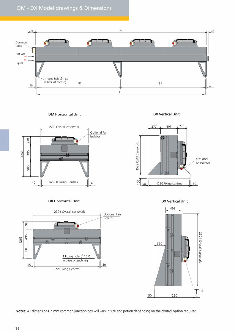
66 67
DM - DX Model drawings & Dimensions
e
Notes: All dimensions in mm common junction box will vary in size and potion depending on the control option required
DM Horizontal Unit DX Vertical Unit
DX Vertical UnitDX Horizontal Unit
1 Fixing hole 15.0 in base of each leg
2221Fixing Centres40 40
1265
500
495
270
2301 Overall caseworkOptional Fan Isolator
1459.0 Fixing Centres40 40
1265
500
495
270
1539 Overall casework
Optional Fan Isolator
495
2301 Overall casew
ork
350
50 501250100
1158
.0 O/
ALL C
ASEW
ORK
1250 Fixing centres50 50100
377 270495
OptionalFan Isolator
1539
O/A
ll C
asew
ork
235
40
70
1 Fixing hole 15.0 in base of each leg
CommonJ/Box
40B1 B1
C
A
Hot Gas
Liquid

66 67
mm
B1 CB2
kgkg
AL
kg
CU
kg
CU AL
mm mmmm
AMode
DM/DX
Dry weightDry weightFans perbank
DM Total unit DX Total unit
D_A112
D_A113
D_A114
D_A122
D_A123
D_A124
D_A132
D_A133
D_A134
D_A142
D_A143
D_A144
D_A152
D_A153
D_A154
D_A162
D_A163
D_A164
D_C143
D_B112
D_B113
D_C134
D_C132
D_C142
D_C133
D_C144
D_C123
D_C114
D_C124
D_C122
D_C113
D_C112
D_B143
D_B152
D_B153
D_B154
D_B123
D_B124
D_B134
D_A172
D_A174
D_A182
D_A173
D_A183
D_B184
D_B142
D_B144
D_B162
D_B163
6
6
6
1
1
1
2
2
2
3
3
3
4
4
4
55
5
2
3
2
6
6
4
4
8
8
7
8
7
7
5
5
5
4
1
1
2
2
1
2
4
3
4
3
3
1
1
4
D_B164
D_C152
D_C153
D_C154 5
5
5
6
1203
3523
245262 300208
234
259
351
402452
492
567
640
653
754
855
802
928
1054
940
1092
1243
466
742
527
1234
1057
970
732
1643
1441
1268
1239
1444
1092
1194
1045
898
850
272310
446
592
349
519
1085
720
805
618
824
278
247
945
1335
1161
988
1411
356
411
518
629741
736
903
1069
964
1187
1409
1189
1468
1745
1399
1734
2068
726
1246
860
2026
1566
1644
1118
2736
2292
2015
1845
2404
1624
2039
1705
1371
1377
392
475
699
1033
559
866
1989
1273
1321
1023
1524
407
339
1655
2472
2054
1637
2427
324
386
464
589714
665
855
1040
822
1133
1380
1088
1401
1708
1285
1661
2030
643
1103
785
1692
1350
1425
930
2694
2202
1934
1700
2364
1494
1777
1445
1144
1160
330428
553
881
519
718
1615
997
1010
773
1228
385
303
1307
1987
1606
1243
2091
277
307
414
474533
580669
757755
874
993
928
1077
1225
1086
1265
1444
539
872
610
1467
1254
1146
860
1906
1668
1469
1429
1677
1260
1414
1236
1058
1002
315
359
543
721
404
632
1366
922
1010
790
1056
312
277
1188
1693
1469
1248
1682
2382
2382
2382
2982
2982
2982
3582
3582
3582
2880
2880
2862
2862
3581
3581
2381
3581
2381
2381
3582
3582
3582
2862
3582
2682
3582
2682
2682
3582
1840
1840
1840
2880
3523
3523
4723
4723
4723
5923
5923
5923
7123
7123
7123
11231123
2323
1123
2323
2323
2803
4243
2803
8563
8563
5683
5683
9523
9523
8323
9523
8323
8323
7123
7123
7123
5683
1723
1723
3523
3523
1723
3523
7123
5323
7123
5323
5323
1363
1363
7123
8923
8923
8923
8563
2342
2342
2342
2942
2942
2942
3542
3542
3542
2821
2821
2822
2822
3541
3541
2341
3541
2341
2341
35423542
3542
2822
3542
2642
3542
2642
2642
3542
3541
3541
3541
2821
1203
2403
24032403
3603
3603
3603
4803
4803
4803
6003
6003
6003
7203
7203
7203
1203
2883
4323
2883
8643
8643
5763
5763
9603
9603
8403
9603
8403
8403
7203
7203
7203
5763
1803
1803
3603
3603
1803
3603
7203
5403
7203
5403
5403
1443
1443
7203
9003
9003
9003
8643
D_B114 1 310 474461 34913631443
D_B122 2 405 593508 46828032883
D_B132D_B133
3
3
561
652
845
1047
711
900
657
765
4243
4243
4323
4323
Notes: Total unit dry weight is dependent upon the coil material used (AL/AV = Copper tubes with Aluminium or Copper tubes with 2 pack epoxy coated aluminium fns, CU = Copper tubes with Copper fins or Copper fins electro-tinned).

68 69
GEA Searle - DV Dry Coolers
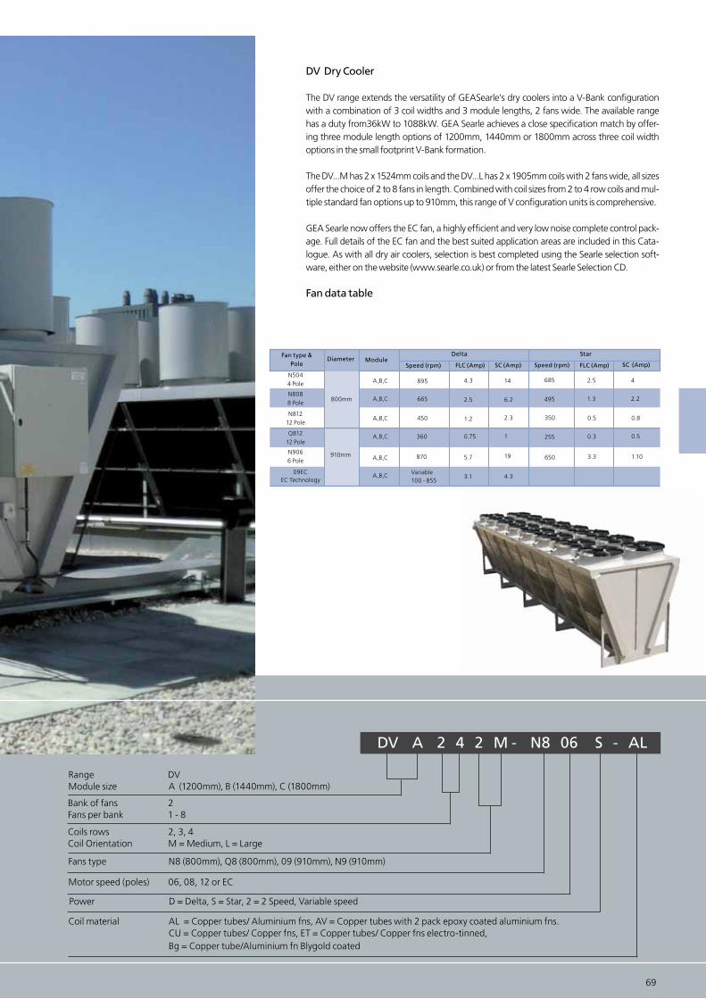
68 69
DV Dry Cooler
The DV range extends the versatility of GEASearle’s dry coolers into a V-Bank configuration with a combination of 3 coil widths and 3 module lengths, 2 fans wide. The available range has a duty from36kW to 1088kW. GEA Searle achieves a close specification match by offer-ing three module length options of 1200mm, 1440mm or 1800mm across three coil width options in the small footprint V-Bank formation.
The DV...M has 2 x 1524mm coils and the DV...L has 2 x 1905mm coils with 2 fans wide, all sizes offer the choice of 2 to 8 fans in length. Combined with coil sizes from 2 to 4 row coils and mul-tiple standard fan options up to 910mm, this range of V configuration units is comprehensive.
GEA Searle now offers the EC fan, a highly efficient and very low noise complete control pack-age. Full details of the EC fan and the best suited application areas are included in this Cata-logue. As with all dry air coolers, selection is best completed using the Searle selection soft-ware, either on the website (www.searle.co.uk) or from the latest Searle Selection CD.
Fan data table
0.75 255 0.3 0.5
870 5.7 650 3.3 1.10
3.1 4.3
1.2 350 0.5 0.8
A,B,C 4.3
2.5
360
450
895
665
1
19
2.3
14
6.2
A,B,C
A,B,C
A,B,C
A,B,C
A,B,C
800mm
910mm
Variable100 - 855
N8088 Pole
Q81212 Pole
N9066 Pole
09ECEC Technology
N5044 Pole
N812 12 Pole
Fan type &Pole
Diameter ModuleSpeed (rpm)
Delta
FLC (Amp) SC (Amp)
Star
Speed (rpm) FLC (Amp) SC (Amp)
495 1.3 2.2
685 2.5 4
DV A 2 4 2 M - N8 06 S - AL
Range DVModule size A (1200mm), B (1440mm), C (1800mm)
Fans type N8 (800mm), Q8 (800mm), 09 (910mm), N9 (910mm)
Power D = Delta, S = Star, 2 = 2 Speed, Variable speed
Coil material AL = Copper tubes/ Aluminium fns, AV = Copper tubes with 2 pack epoxy coated aluminium fns. CU = Copper tubes/ Copper fns, ET = Copper tubes/ Copper fns electro-tinned, Bg = Copper tube/Aluminium fn Blygold coated
Motor speed (poles) 06, 08, 12 or EC
Bank of fans 2Fans per bank 1 - 8
Coils rows 2, 3, 4Coil Orientation M = Medium, L = Large
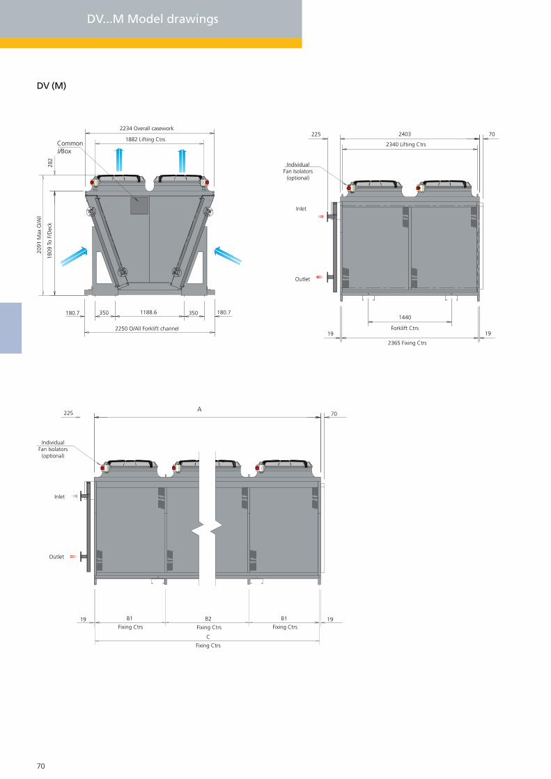
70 71
IndividualFan Isolators
(optional)
225 70
1919Fixing Ctrs
DV...M Model drawings
DV (M)
282
2234 Overall casework
CommonJ/Box
1882 Lifting Ctrs
2091
Max
O/A
ll
1809
To
F/D
eck
2250 O/All Forklift channel
180.7 350 1188.6 350 180.7
225 2403
2340 Lifting Ctrs
70
IndividualFan Isolators
(optional)
Inlet
Outlet
1440
Forklift Ctrs
2365 Fixing Ctrs
19 19
B1
Fixing Ctrs
B2
Fixing Ctrs
B1
Fixing Ctrs
C
A
Inlet
Outlet

70 71
DV...L Model drawings
DV (L)
282.
0
928 . 0
225 70
2340.0 Lifting Ctrs
2403
IndividualFan Isolators
(optional)
19 19
144
Forklift Ctrs
2365 Fixing Ctrs
2234 Overall casework
1886 Lifting CtrsCommonJ/Box
282.
0
311350928350311
2250 O/All Forklift channel
2449
Max
O/A
ll
2167
To
F/D
eck
IndividualFan Isolators
(optional)
225 70
1919Fixing Ctrs
B1
Fixing Ctrs
B2
Fixing Ctrs
B1
Fixing Ctrs
C
282.
0
A
Inlet
Outlet
Inlet
Outlet

72 73
AL/AV CU/ET
DVA 222223
224
232
233
234
242
243
244
252
253
254
262
263264272
273
274
282
283
284222
223224
232
233
234
242
243244
252
DVA
DVA
DVA
DVA
DVA
DVA
DVA
DVADVA
DVA
DVA
DVA
DVA
DVA
DVA
DVA
DVA
DVA
DVA
DVA
DVB
DVBDVB
DVB
DVB
DVB
DVB
DVBDVB
DVB
B2
mm mm
C
mm
B1
mm
MM
M
M
M
M
M
M
MM
M
M
M
M
MM
M
M
M
M
M
MM
M
M
MM
M
M
MM
44
6
4
6
6
8
8
108
10
10
12
12
1412
8
8
6
6
6
44
4
16
16
16
14
14
810
kg kg
253DVB M 10
254262263264DVB
222DVC
223224
232
233234242
243244252253
254DVC M 10
DVC M 10
DVC M 10
DVC M 8
DVC M 8
DVC M 8
DVC M 6
DVC M 6
DVC M 6
DVC M 4
DVC M 4
M 4
M 12
DVB M 12
DVB M 12
DVB
N/AN/A
1200
1200N/A
12002400
12002400
2400
1200
1200
24002400
2400
2400
2400
3400
34002400
3400N/A
1440
N/AN/A
1440
1440
2880
2880
28801400
1400
2720
N/A
1840
1840184036003600
360018001800
1800
N/AN/A
272027201400
23652365
3565
35652365
35654765
59654765
4765
5965
5965
71657165
7165
8365
8365
9565
95658365
95652845
4285
28452845
4285
4285
5725
5725
57257165
7165
3565
8965
8965896571657165
716553655365
5365
35653565
8602860286027165
N/AN/A
1183
1183N/A
11831183
23831183
1183
2383
2383
23832383
2383
2382
2382
2382
23822382
2382N/A
1422
N/AN/A
1422
1422
1422
1422
14222862
2862
1782
3565
3565356517821782
178217821782
1782
17821782
2862286228622862
24032403
3603
36032403
36034803
60034803
4803
6003
6003
72037203
7203
8403
8403
9603
96038403
96032883
4323
28832883
4323
4323
5763
5763
57637203
7203
9003
9003900372037203
720354035403
5403
36033603
3603
8640864086407203M 10
720788
1189
1087857
12921449
18111722
1585
1981
2152
25352377
2173
2535
2774
3170
28983013
830912
1367
1244994
1490
1659
18231986
3443
2073
2277
2977
3545246623822177
197317871633
1480
11921089
987
2978273324872482
8661008
1518
13061149
17311741
21772307
2024
2530
2884
34603036
2612
3048
3542
4049
34834037
10051175
1762
15081345
2017
2010
2689
2350
4614
2512
2936
4075
2721301532602836
241224452127
1809
16311418
1206
4032352330153360
Model
Approx Dry weightACasework
overallSize No. fans
Dimensions DV...M
Notes: Total unit dry weight is dependent upon the coil material used (AL/AV = Copper tubes with Aluminium or Copper tubes with 2 pack epoxy coated aluminium fns, CU = Copper tubes with Copper fins or Copper fins electro-tinned).
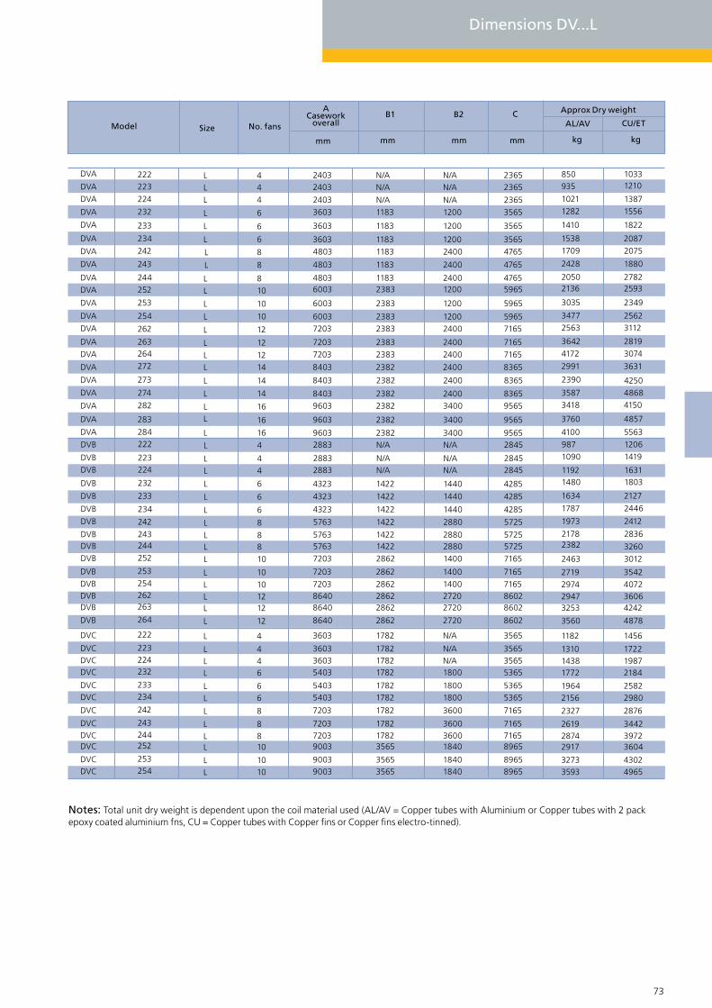
AL/AV CU/ETB2
mm mm
C
mm
B1
mm kg kg
Model
Approx Dry weightACasework
overallSize No. fans
72 73
DVA 222223
224
232
233
234
242
243
244
252
253
254
262
263264272
273
274
282
283
284222
223224
232
233
234
242
243244252
DVA
DVA
DVA
DVA
DVA
DVA
DVA
DVADVA
DVA
DVA
DVA
DVA
DVA
DVA
DVA
DVA
DVA
DVA
DVA
DVB
DVBDVB
DVB
DVB
DVB
DVB
DVBDVBDVB
LL
L
L
L
L
L
L
LL
L
L
L
L
LL
L
L
L
L
L
LL
L
L
LL
L
L
LL
253DVB L254262263
264DVB
222DVC L223224232
233234
242
243244252
253254DVC L
DVC L
DVC LDVC L
DVC L
DVC L
DVC L
DVC L
DVC L
DVC L
DVC L
L
DVB L
DVB L
DVB
N/AN/A
1200
1200N/A
12002400
12002400
2400
1200
1200
24002400
2400
2400
2400
3400
34002400
3400N/A
1440
N/AN/A
1440
1440
2880
2880
28801400
1400
2720
N/A
18401840
184036003600
3600
18001800
1800N/AN/A
272027201400
23652365
3565
35652365
35654765
59654765
4765
5965
5965
71657165
7165
8365
8365
9565
95658365
95652845
4285
28452845
4285
4285
5725
5725
57257165
7165
3565
8602
89658965
896571657165
7165
53655365
536535653565
860286027165
N/AN/A
1183
1183N/A
11831183
23831183
1183
2383
2383
23832383
2383
2382
2382
2382
23822382
2382N/A
1422
N/AN/A
1422
1422
1422
1422
14222862
2862
1782
2862
35653565
356517821782
1782
17821782
178217821782
286228622862
24032403
3603
36032403
36034803
60034803
4803
6003
6003
72037203
7203
8403
8403
9603
96038403
96032883
4323
28832883
4323
4323
5763
5763
57637203
7203
3603
90039003
900372037203
7203
54035403
540336033603
8640
864086407203L
44
6
4
6
6
8
8
108
10
10
12
12
1412
8
8
6
6
6
44
4
16
16
16
14
14
810
10
4
1010
1088
8
66
644
12
121210
850935
1410
12821021
15381709
21362050
2428
3035
3477
41723642
2563
2991
2390
3760
34183587
9871090
1634
14801192
1787
1973
21782382
4100
2463
2719
1182
35933273
291728742619
2327
21561964
177214381310
3560
325329472974
10331210
1822
15561387
20872075
25932782
1880
2349
2562
30742819
3112
3631
4250
4857
41504868
12061419
2127
18031631
2446
2412
3260
2836
5563
3012
3542
1456
49654302
360439723442
2876
29802582
218419871722
4878
424236064072
Dimensions DV...L
Notes: Total unit dry weight is dependent upon the coil material used (AL/AV = Copper tubes with Aluminium or Copper tubes with 2 pack epoxy coated aluminium fns, CU = Copper tubes with Copper fins or Copper fins electro-tinned).

74 75
Installation and Location guidance
Consideration should be given to pipework associated with the installation which can be either an obstruction to air flow or a heat source to the air enteringthe coil. Other adjacent plant either requiring an air supply or dissipating air will affect the air flow onto the unit. The colour of the surface on which the units are mounted and/or surrounding areas can create high solar gains, increasing the entering air temperature considerably. A 5K temperature increase over and above ambient is not unusual. This obviously has a serious effect on the performance.
Adjacent building styles, plant and prevailing winds can often cause air currents, which, in turn, can create down draughts, consequently forcing the discharge air back down into the air intake stream, causing high air entering temperatures and subsequent loss of performance. Vertical units must not be installed when either 16 pole (star/delta) or 12pole (star) connected motors are employed. The reason for this restriction is that an adverse effect of the prevailing wind can overcome the power of the motor, making it impossible to start. When vertical units are to be installed, they should be orientated so that the air flow direction is similar to that of the summer prevailing wind. Also, the coil should be, as far as is practical, shaded from direct sunlight.
Fig 1
Single unit with no restriction within the units length has no limita-tions in use. For dimensions W and L refer to the dimensions table
Fig 2
Parapet wall is not restrictive in this instance provided y>2x.
Solid obstructione.g duct, plant, wall Support plane
Fig 3
Multiple units with no restrictions within a distance equal to the units length have few limitations. However, the distance between units when more than 2 units in line are required is more critical. In this instance, it is worth considering increasing the leg height to give improved air circulation
Fig 4
The dimension 0.15L is critical only if more than one unit is to be installed. If only one unit is installed, it can be located adjacent to the solid wall.
Solid wall
W
L
0.3L 0.15L 0.3L
YX
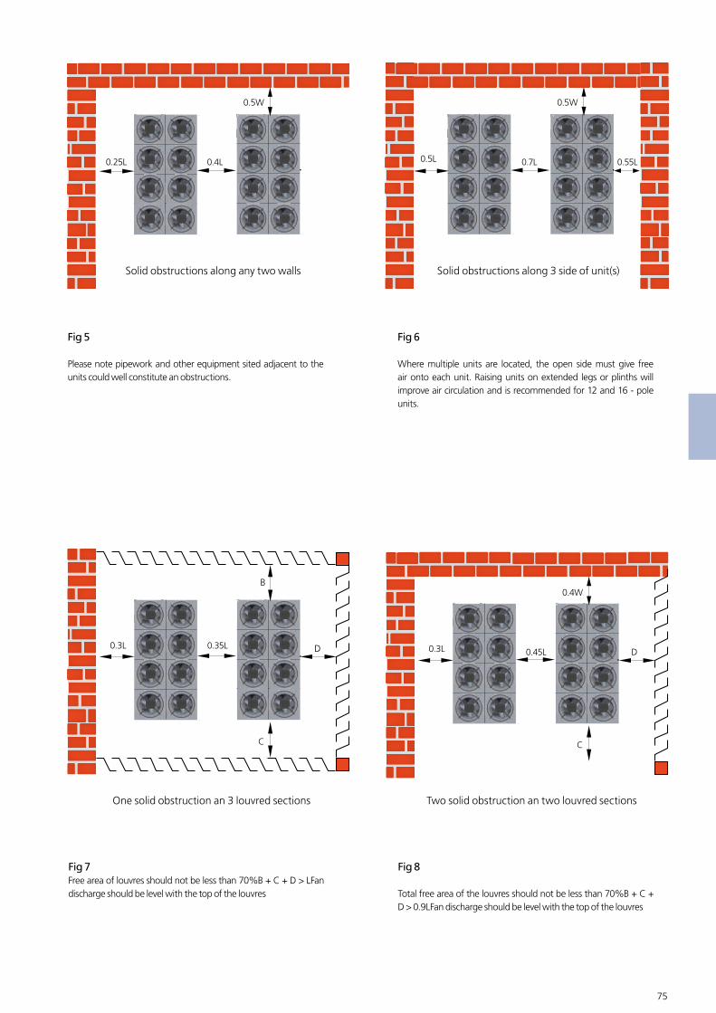
74 75
Fig 5
Please note pipework and other equipment sited adjacent to the units could well constitute an obstructions.
Fig 6
Where multiple units are located, the open side must give free air onto each unit. Raising units on extended legs or plinths will improve air circulation and is recommended for 12 and 16 - pole units.
Solid obstructions along any two walls Solid obstructions along 3 side of unit(s)
Fig 7Free area of louvres should not be less than 70%B + C + D > LFan discharge should be level with the top of the louvres
Fig 8
Total free area of the louvres should not be less than 70%B + C + D > 0.9LFan discharge should be level with the top of the louvres
One solid obstruction an 3 louvred sections Two solid obstruction an two louvred sections
0.35L0.3L D
B
C
0.45L0.3L D
0.4W
C
0.4L0.25L
0.5W
0.7L0.5L
0.5W
0.55L
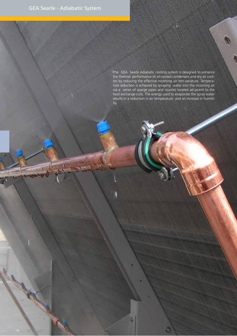
The GEA Searle Adiabatic cooling system is designed to enhance the thermal performance of air-cooled condensers and dry air cool-ers by reducing the effective incoming air tem-perature. Tempera-ture reduction is achieved by spraying water into the incoming air via a series of sparge pipes and nozzles located ad-jacent to the heat exchange coils. The energy used to evaporate the spray water results in a reduction in air temperature and an increase in humid-ity.
GEA Searle - Adiabatic System
76 77

Adiabatic System
The total enthalpy of the air remains the same. On a typical unit ftted with 12 pole fansets operating in an ambient of 32°C db and 40% RH a depression of 80% can be achieved, resulting in an effective incoming air tempera-ture of 24°C Maximum depression on units ftted with 6 pole Delta motors is 60%. For alternative conditions please refer to enclosed tables.
System Description
GEA Searle Adiabatic cooling systems are made up of two principal assem-blies. The adiabatic control box, which can be factory ftted to air-cooled condensers and dry air coolers. The sparge and nozzle assembly is fac-tory ftted to V bank units and supplied loose (for shipment) on fat bed units. These items are also available as a retro ft kit for site upgrades. Three versions of the adia-batic control box are available:
Option 1
Without a pressurisation pump where the supply water pressure, at design fow rate, is not less than 5 bar.
Option 2
A low fow rate pressurisation pump where the supply water pressure, at design fow rate, is not less than 2 bar.
Option 3
A high fow rate pressurisation pump where the supply water pressure, at design fow rate, is not less than 2 bar.
All adiabatic control boxes are ftted with water strainer, mains inlet solenoid valve, vent solenoid valve, pressure regulator and gauge, pressure switch, ultraviolet lamp, scale inhibitor and a 230-volt control panel. The electronic controls are mounted in a polycarbonate box and contain a mains isolator, adiabatic sequence controller and transformer. Water is sprayed into the air stream via a sparge system made of 22mm copper pipe ftted with atomising nozzles and connected together with push fttings. A drain solenoid is ftted to the lowest part of the system.
Applications
Adiabatic systems can be applied to dry air coolers and air cooled condens-ers when there is a reason-able difference between the dry bulb and wet bulb temperatures. The following benefts and features may be achieved when ftting adiabatic systems:
Fluid temperatures lower than the ambient dry bulb when there is suffcient difference between the dry bulb and wet bulb.
Reduction in physical size of plant.
Increasing in capacity on existing dry systems.
Standby - used as emergency capacity on critical applications or upgrades.
A sequence of operation has been developed:
To ensure no free standing water is left in the system when inactive.
Water in the supply pipe fushes the system before high pressure spraying starts.
When water is passed through the ultra-violet lamp the dose of UV radia-tion received is lethal to pathogens - including Legionella - eliminating any health risks. Searle adiabatic cooling systems conform to the design require-ments of ACOP L8 “control of Legionella bacteria in water systems”.
The adiabatic system is normally started from an external volt free signal provided by a capacity control system, BMS or emergency override. The ultraviolet lamp is switched on and the vent and drain solenoids are closed. After a set time delay the main solenoid is opened to fush the system before the pump is started.
The pressure in the system and operation of the ultra-violet lamp are monitored. If the pressure falls below 1 bar or the lamp fails the system will be closed down. The mains solenoid and pump will cycle on and off as the load varies. The ultravio-let lamp and vent/drain solenoids are cycled off at the end of the day’s opera-tion, ensuring the lamp operates at full power and that fushing is not re-peated unnecessarily, no free standing water is left in the system when inactive. At the end of the sequence, the system (downstream of the main sole-noid valve) has been fully drained.
76 77
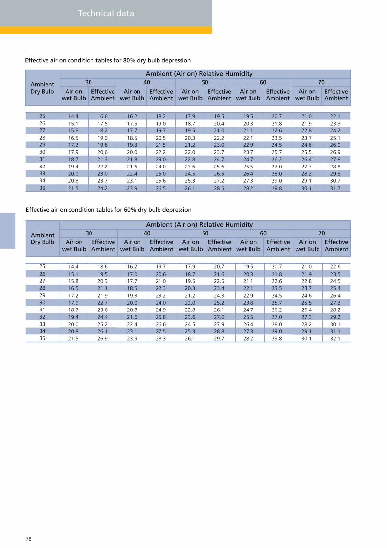
78 79
Effective air on condition tables for 80% dry bulb depression
Effective air on condition tables for 60% dry bulb depression
25 14.4 16.6 16.2 18.2 17.9 19.5 19.5 20.7 21.0 22.123.324.225.126.026.927.828.829.830.731.7
21.922.823.724.625.526.427.328.229.130.1
21.822.623.524.525.726.227.028.029.029.8
20.321.122.122.923.724.725.526.427.328.2
20.421.022.223.023.724.725.626.527.228.5
18.719.520.321.222.022.823.624.525.326.1
19.019.720.521.522.223.024.025.025.626.5
17.517.718.519.320.021.821.622.423.123.9
17.518.219.019.820.621.322.223.023.724.2
15.115.816.517.217.918.719.420.020.821.5
26
353433323130292827
25 14.4 18.6 16.2 19.7 17.9 20.7 19.5 20.7 21.0 22.623.524.525.426.427.328.229.230.131.132.1
21.922.823.724.625.526.427.328.229.130.1
21.822.623.524.525.726.227.028.029.029.8
20.321.122.122.923.824.725.526.427.328.2
21.622.523.424.325.226.127.027.928.829.7
18.719.520.321.222.022.823.624.525.326.1
20.621.022.323.224.024.925.826.627.528.3
17.017.718.519.320.020.821.622.423.123.9
19.520.321.121.922.723.624.425.226.126.9
15.115.816.517.217.918.719.420.020.821.5
26
353433323130292827
AmbientDry Bulb Air on
wet BulbEffectiveAmbient
Air onwet Bulb
EffectiveAmbient
Air onwet Bulb
EffectiveAmbient
Air onwet Bulb
EffectiveAmbient
Air onwet Bulb
EffectiveAmbient
7060504030Ambient (Air on) Relative Humidity
Technical data
AmbientDry Bulb Air on
wet BulbEffectiveAmbient
Air onwet Bulb
EffectiveAmbient
Air onwet Bulb
EffectiveAmbient
Air onwet Bulb
EffectiveAmbient
Air onwet Bulb
EffectiveAmbient
7060504030Ambient (Air on) Relative Humidity

78 79
Control box and pipe schematic
Sparge and nozzle assembly Control box
Downward pointing spray nozzles
Downward pointing spray nozzles
StarinerMains solenoid
0 - 6 Bar pressure regulator
Rest
ricto
r
0 - 6 Bar gauge
Pump
Non return valve
Vent solenoid
UV lamp
22mm ODmain inlet
0 - 6 Bar guage
Lowest free drainingpoint system
Mechanical descaler
PressureSwitch
Drain solenoid

80 81
GEA Searle offers a range of Controls solutions, suitable for the range of Air Cooled Condensers and Dry Air Coolers.These can be supplied fac-tory-ftted with all controls software installed and functioning so that the unit can be simply con-nected up and pow-er supplied. This enables the installation time to be dramatically reduced and avoids problems using 3rd party controls.
GEA Searle - Control options

80 81
Controls options for GEA SearleCondensers and Dry Cooers
Major benefts
Reduced installation costs Latest controls systems installed Factory ftted system
Controls Overview
The new control range is based on a modular form starting with the basic package and the vari-ous control added as extras. Except for very small units and for EC Remote Condensers and DACs, which will be 230V 50/60Hz, the Control will be 24V 50/60Hz.
Control Options
No Controls :- Motor Wiring terminated in a junc-tion box or Isolators, al-lowing either star or delta connections.
FCB ;- Fan Contactor Box (Standard AC Motors)
A single metal IP55 enclosure is used containing the following.
Mains Isolator.
Motor Starter and Contactor per fan as standard
Alternatively to cut costs on double bank units a Motor Starter and Contac-tor per pair of fans is an option. On single bank units each contactor coil is terminated to allow the Customer to provide a signal for each contactor to close. For double bank units, the contactors will be controlled in pairs Further steps can be obtained by applying a 2 Speed Strategy (Star Delta control). This requires 2-3 contactors per fan and is a fairly costly option. Standard practice on a 12-fan unit would 6 stages of Low Speed (“Star”) and 2 stages 6 Fans each of High Speed (“Delta”).
FCT Fan Control Temperature & FCP Fan Control Pressure.
The FCT/FCP will be an addition to the FCB, and provides stand-alone con-trol of the unit.
Up to 8 Stages of step control.
0-10V Analogue output for FSC control.
Up to 2 Temperature Sensors or 2 Pressure Transducers (can be connected).
Dual sensors can be employed in Dual Coil units and either Highest or Average control can be applied.
Alternatively with a single sensor 2 set ponit can be programmed to provide “Winter Free Cooling”activated from a BMS system.

82 83
EC Fansets
EC Fan Sets (Electronic Commutation)
The EC fansets provide a very good Fan Speed Control solution due to the internal electronics within the fanset enabling simple control. EC fan-sets are now the preferred choice for Condenser applications due to the varying load requirements during a normal day-night cycle. How-ever, due to the inherent effciency of EC motors, their use in fuid coolers is now becoming more common.There are various control options, de-pending on the selection of the controller and whether back-up control is required.
Junction Box Termination
3 Phase supply 4 core cable10V, 0-10V Signal, Grnd - cores 2, 3Com, N/O Alarm (close on fault) cores 4 & 5 7 Core screened cable RSA, RSB modbus coms - Cores 6 & 7
Controller options
Main Isolator, and then a MCB for each fan set with the additional options below will be provid-ed. On very large units 1 MCB per par of fans will be provided. The EC technology provides Over-load Protection so only Short Circuit protection is required.
Directly connected Transducer
A “Closed Loop Control “ strategy is applied to one fan set designated as the “Master” and any additional fan sets designated as “Slaves”. This approach requires an external device such as a Laptop to set up the Master and alter the control settings.
Single Controller
There are 3 main options for a single controller:1) Searle sequential controller 2) Millenium 3) RDM
EC FansetsCondensers and Dry Coolers
Fanspeed
?
Speed or noise levelneeds to be separated
No
No
Fan mounted isolator,1 per fan
Motor/Isolator terminalsfor customer wiring
Un-wired Unit Junction boxMotor Switchgears
?
1. IP55 enclosure2. Main isolator3. Motor starter + contactor per fan
Master: SlaveDirectly connected transducer
1. Main isolator2. 1 MCB per fanset3. Master fansets set-up via laptop/PDA
1. Pressure switches/thermostats2. Controllers/transducers
Unit provided with terminals for 0-10V signal
No
1. 8 stage step control2. 0-11V output for EC3. Noise level setting option4. 2 auxiliary stage (Adiabatic)
Searle Controller(FCP/FCT)
Industry Standard controller(like millenium & RDM)
1. Monitor transducer2. 0-11V in parallel to all fansets3. Set paramenters via controller front panel
Yes
Isolators?
Yes
Junction box termination 3Ph (4 core)0-10v,Ground (core 2, 3)Com, N/O Alam (core 4, 5)RSA, RSB - RS 485 (core 6, 7)
FCBFan contactor
Externalcontroller
Basiccontrol
FSCBackup
?
Yes
Yes
Backup Control

82 83
AC Fansets
All operate in a similar manner by reading a transducer input and apply-ing a 0-10V signal in parallel to all fansets. The GEA searle controlleral-lows operating limits to be set in terms of noise level. Fansets can be preset to have an upper speed limit so as not to exceed specifed noise requirements.
Backup Control
Backup control can be provided for any FSC strat-egy and can take the form of Pressure switches or thermostats for small condensers or DACs and extra controllers and transducers for larger units. This requirement is becoming more common.
AC Fanset
FSC Fan Speed Control (Temperature or Pressure) The Inverter and FCB will be contained in one enclosure. Inverter Control will change the applied frequency to the motor; the Inverter can be pro-grammed to employ an inbuilt PID control strategy, which can also shut down the fans when they are not required to run. Alternatively an external signal from a controller such as the RDM Varipac can be used this would allow easy connection to a network for monitoring purposes. For all EBM fan sets it is mandatory for Sinusoidal Filtering to be used. Also Consider EC fansets as an alternative they are generally more effcient and cost effec-tive.
Motor/Isolator terminalsfor customer wiring
AC FansetsCondensers and Dry Coolers
Fan mounted isolator,1 per fan
No
Un-wired Unit Junction box
NoFans switched via remote volt free contacts
1. IP55 enclosure2. Main isolator3. Motor starter + contactor per fan
1. Step control-up to 8 stages2. Additional to FCB3. Up to 2 temperature sensors4. 0-10V Analogue output available
1. Step control-up to 8 stages2. Additional to FCB3. Up to 2 temperature sensors4. 0-10V Analogue output available
1. Pressure switches/thermostats2. Controllers
1. EMC wiring required2. Non-noise sensitive applications3. Triacs approved by motor supplier
1. One enclosure containing FCB + Inverter2. Sinusoidal filter required with EMB fanset
Junction Box Termination wired for Star or Delta
connection
FCBFan Contactor Box
FanControl
?
Fan Speed
Control(FSC)?
FSCBackup
?
FCTFan Control Tempature
Triac Control
Inverter control
FCPFan Control Pressure
Yes
Yes
Yes
Yes
Isolators?
Motor Switchgears
?
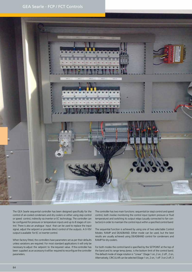
84 85
GEA Searle - FCP / FCT Controls
The GEA Searle sequential controller has been designed specifically for the control of air-cooled condensers and dry coolers or either using step control or speed control, indirectly via inverter or EC technology. The controller can be configured for pressure or temperature inputs and up to 8 stages of con-trol. There is also an analogue input that can be used to replace the input signal, adjust the setpoint or provide direct control of the outputs. A 0-10V output is available for EC or inverter control.
When factory fitted, the controllers have parameters set as per their defaults unless variations are required. For most standard applications it will only be necessary to adjust the setpoint to the required value. If the controller has been supplied as an accessory it will be required to reconfigure the controller parameters.
The controller has two main functions: sequential (or step) control and speed control, both involve monitoring the control input (system pressure or fluid temperature) and switching its output relays (usually connected to fan con-tactors) in order to maintain the control input within a specified control band
The sequential function is achieved by using one of two selectable Control Modes: RAMP and DEADBAND. Either mode can be used, but the best results are usually achieved using DEADBAND control for condensers and RAMP for dry coolers.
For both modes the control band is specified by the SETPOINT at the top of the band and its range temp./press. is the bottom limit of the control band. The default mode of stage rotation is “Linear” (Stage 1 on, 2 on, 2 off , 2 on, Alternatively, CIRCULAR can be selected (Stage 1 on, 2 on, 1 off 3 on 2 off, 3
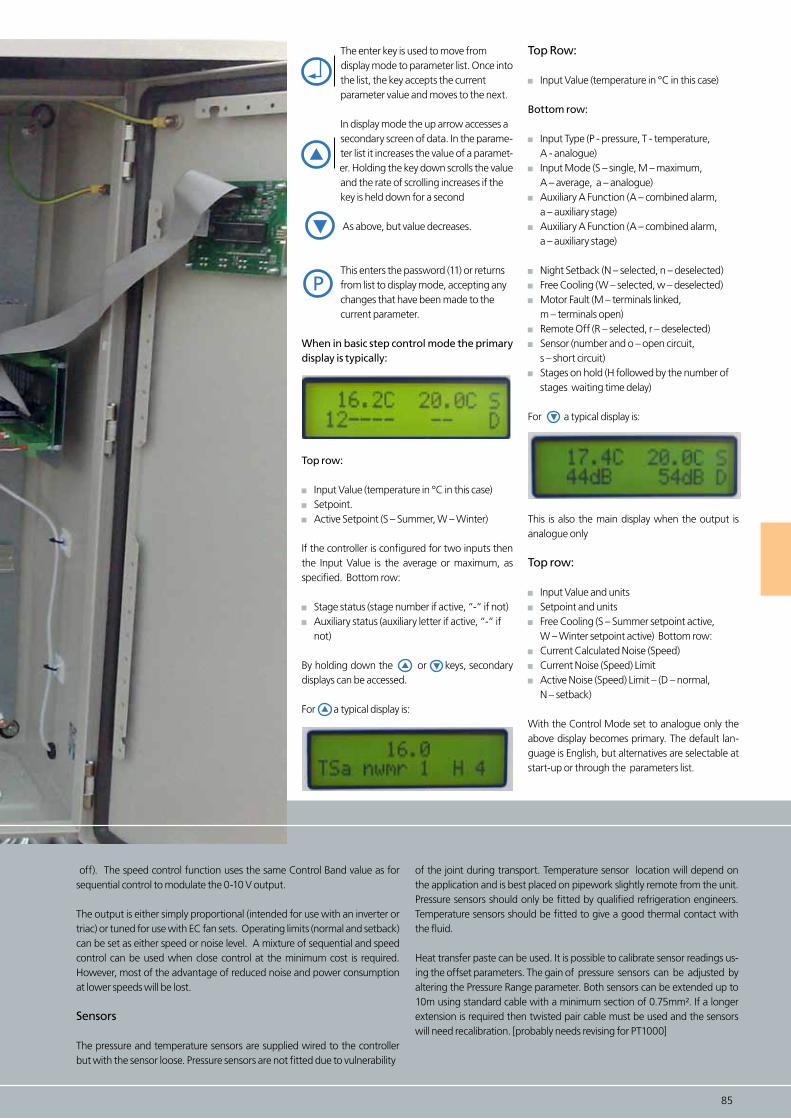
The enter key is used to move from display mode to parameter list. Once into the list, the key accepts the current parameter value and moves to the next.
In display mode the up arrow accesses a secondary screen of data. In the parame- ter list it increases the value of a paramet- er. Holding the key down scrolls the value and the rate of scrolling increases if the key is held down for a second
As above, but value decreases.
This enters the password (11) or returns from list to display mode, accepting any changes that have been made to the current parameter.
When in basic step control mode the primary display is typically:
Top row:
Input Value (temperature in °C in this case) Setpoint. Active Setpoint (S – Summer, W – Winter)
If the controller is configured for two inputs then the Input Value is the average or maximum, as specified. Bottom row:
Stage status (stage number if active, “-“ if not) Auxiliary status (auxiliary letter if active, “-“ if not)
By holding down the or keys, secondary displays can be accessed.
For a typical display is:
84 85
off). The speed control function uses the same Control Band value as for sequential control to modulate the 0-10 V output.
The output is either simply proportional (intended for use with an inverter or triac) or tuned for use with EC fan sets. Operating limits (normal and setback) can be set as either speed or noise level. A mixture of sequential and speed control can be used when close control at the minimum cost is required. However, most of the advantage of reduced noise and power consumption at lower speeds will be lost.
Sensors
The pressure and temperature sensors are supplied wired to the controller but with the sensor loose. Pressure sensors are not fitted due to vulnerability
P
Top Row:
Input Value (temperature in °C in this case)
Bottom row:
Input Type (P - pressure, T - temperature, A - analogue) Input Mode (S – single, M – maximum, A – average, a – analogue) Auxiliary A Function (A – combined alarm, a – auxiliary stage) Auxiliary A Function (A – combined alarm, a – auxiliary stage) Night Setback (N – selected, n – deselected) Free Cooling (W – selected, w – deselected) Motor Fault (M – terminals linked, m – terminals open) Remote Off (R – selected, r – deselected) Sensor (number and o – open circuit, s – short circuit) Stages on hold (H followed by the number of stages waiting time delay)
For a typical display is:
This is also the main display when the output is analogue only
Top row:
Input Value and units Setpoint and units Free Cooling (S – Summer setpoint active, W – Winter setpoint active) Bottom row: Current Calculated Noise (Speed) Current Noise (Speed) Limit Active Noise (Speed) Limit – (D – normal, N – setback)
With the Control Mode set to analogue only the above display becomes primary. The default lan-guage is English, but alternatives are selectable at start-up or through the parameters list.
of the joint during transport. Temperature sensor location will depend on the application and is best placed on pipework slightly remote from the unit. Pressure sensors should only be fitted by qualified refrigeration engineers. Temperature sensors should be fitted to give a good thermal contact with the fluid.
Heat transfer paste can be used. It is possible to calibrate sensor readings us-ing the offset parameters. The gain of pressure sensors can be adjusted by altering the Pressure Range parameter. Both sensors can be extended up to 10m using standard cable with a minimum section of 0.75mm². If a longer extension is required then twisted pair cable must be used and the sensors will need recalibration. [probably needs revising for PT1000]

The Millenium controller is a versatile programmable logic controller, which Searle has adopted as either a main or backup controller. Using proprietary software, the controller can be used in a variety of applications and is easily setup via the front programming port, with simple front controls.
The controller will start to run the fans at just above the Set Point and will ramp up the speed to the Set Back Speed as the pressure increases. The Con-trol Band determines the rate at which the speed increases. With the default settings the Fan Sets begin to run at just above 12 bar and rise to 50% speed at 13.5 bar (3 bar Control Band). The controller then will allow the pressure to drift up to the High Pressure Full Speed value (default of 20bar), when the controller will ramp the fans to full speed.
The Fan Sets will continue to run at full speed until the pressure falls to the top end of the control band where the controller will resume the set back speed control. When the controller is employed as a Backup controller the display will indicate that it is disabled under normal operation.
86 87
GEA Searle - Millenium Controller

Note: 1) HP Override is only applicable in dual controller applications. 2) Transducer offset will not be updated until “OK” is pressed.
When the controller is used in Backup applications:- Backup can be forced by pressing “A”&”B” simulta-neously. Reset to primary Control can be achieved by pressing “A”&”ESC” simultaneously.
86 87
press and hold toaccess parameters
press to navigate parameters pages
press to exit parameters pages
press and hold toaccess parameters or confirm setting
press to select and raise valuepress to select
and lower value
Programming port
45%). Press and hold down “OK & “B” for 5 Sec-onds. The controller will remain in this mode. To exit this feature press “B” & “ESC”.
Press and hold down “A” until the first set of parameters appears.
Use the “+” &”-“ buttons until the parameter required is highlighted then press “OK” and the parameter will lash. Use “+” or “-“ to adjust the reading then press “OK” to confirm the setting.
Use the “+” &”-“ again buttons until the parameter required is highlighted and repeat. Press “B” to move to the next Menu page and repeat step 2 as necessary.
Press “ESC” at any time to return to exit parameters.
When the controller is employed as a Backup con-troller the display will indicate that it is disabled under normal operation. The controller monitors the discharge Pressure and will assume control when the HP Override value is exceeded (default 21 bar), and will remain in control until manually reset. Should the Pressure Transducer signal fail this will be indicated on the display and the Fan Sets will run at the Fault Speed, if the controller is enabled.
Dry Testing
The Fan Sets can be run without Pressure in the Condenser by selecting the Test Mode (Default
First Parameter page
Second Parameter page
COND Set PNT
COND CNTL BND
HP Override P
COND Backup Del
CONDTX offset
Setback Speed
HP Full Speed
Fault Speed
8.0
0.5
9.0
10
10
10
10
10
22.0
8.0
22.0
300
10.0
100
22.0
100
12.0
3.0
21.0
20
0
50
20.0
45
BAR
BAR
BAR
SECS
BAR
%
%
Control Band
High Pressure Override setting
Delay Time For Backup to start
Transducer Calibration
Normal Maximum speed
High Pressure Full Speed
TX Fail and Dry Test Speed
Condenser Set Point
Parameter Min Max Def RemarksUnit
Note: Dry cooler Version now available
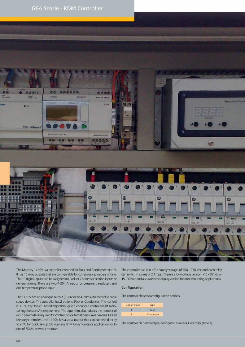
88 89
The Mercury 11-10V is a controller intended for Pack and Condenser control. It has 10 relay outputs that are configurable for compressors, loaders or fans. The 10 digital inputs can be assigned for Pack or Condenser section inputs or general alarms. There are two 4-20mA inputs for pressure transducers and one temperature probe input.
The 11-10V has an analogue output (0-10V dc or 4-20mA) to control variable speed devices. The controller has 2 options, Pack or Condenser. The control is a “Fuzzy logic” based algorithm, giving enhanced control whilst main-taining the starts/hr requirement. The algorithm also reduces the number of input parameters required for control; only a target pressure is needed. Like all Mercury controllers, the 11-10V has a serial output that can connect directly to a PC for quick set-up (PC running RDM Communicator application) or to one of RDMs’ network modules.
The controller can run off a supply voltage of 100 - 250 Vac and each relay can switch in excess of 2 Amps. There is a low voltage version : -10 - 35 Vdc or 15 - 30 Vac and also a remote display version for door mounting applications.
Configuration
The controller has two configuration options
The controller is delivered pre-configured as a Pack Controller (Type 1)
GEA Searle - RDM Controller
Display Value Type
1 Pack
2 Condenser
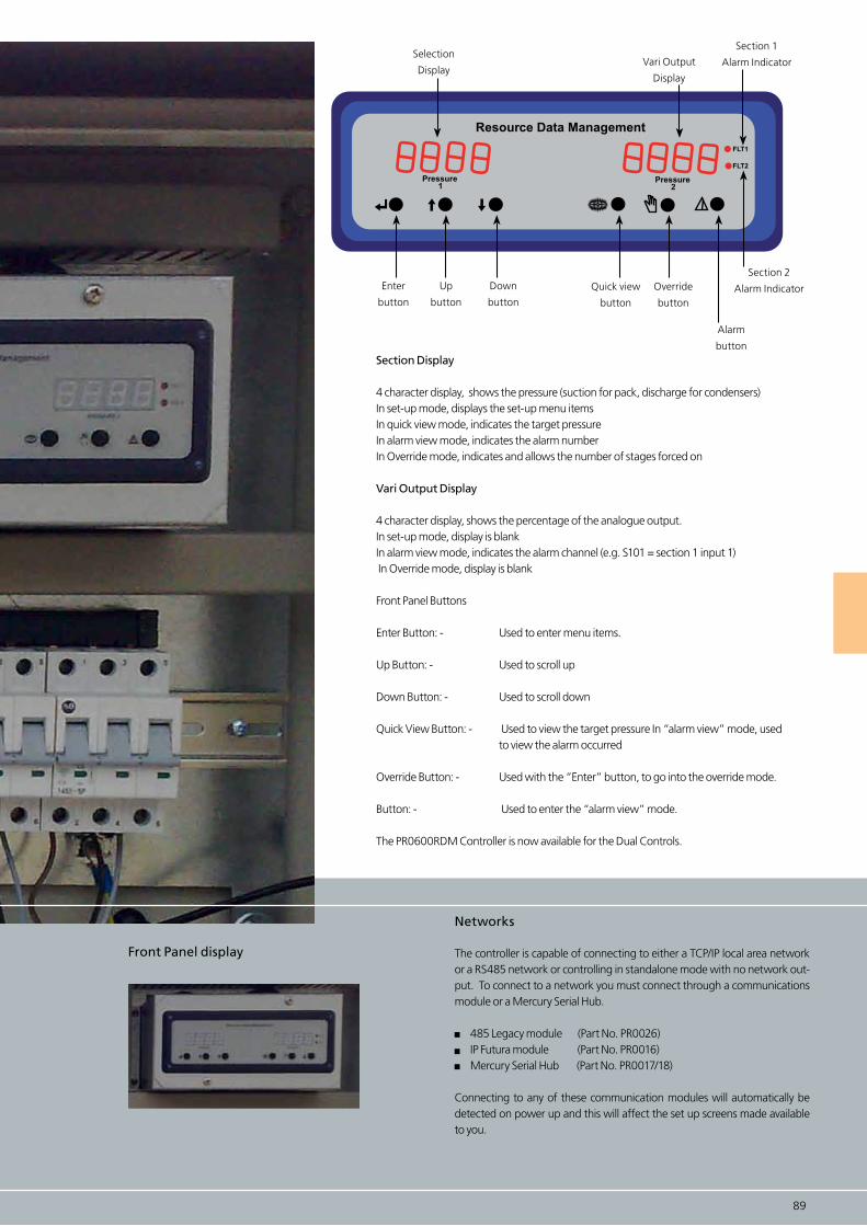
88 89
Front Panel display
Networks
The controller is capable of connecting to either a TCP/IP local area network or a RS485 network or controlling in standalone mode with no network out-put. To connect to a network you must connect through a communications module or a Mercury Serial Hub.
485 Legacy module (Part No. PR0026) IP Futura module (Part No. PR0016) Mercury Serial Hub (Part No. PR0017/18)
Connecting to any of these communication modules will automatically be detected on power up and this will affect the set up screens made available to you.
Resource Data Management
Pressure 1
Pressure 2
FLT1
FLT2
Vari Output
Display
Section 1
Alarm Indicator
Down
button
Quick view
button
Override
button
Alarm
button
Selection
Display
Section 2
Alarm IndicatorUp
button
Enter
button
Section Display
4 character display, shows the pressure (suction for pack, discharge for condensers) In set-up mode, displays the set-up menu items In quick view mode, indicates the target pressure In alarm view mode, indicates the alarm number In Override mode, indicates and allows the number of stages forced on
Vari Output Display
4 character display, shows the percentage of the analogue output. In set-up mode, display is blank In alarm view mode, indicates the alarm channel (e.g. S101 = section 1 input 1) In Override mode, display is blank
Front Panel Buttons
Enter Button: - Used to enter menu items.
Up Button: - Used to scroll up
Down Button: - Used to scroll down
Quick View Button: - Used to view the target pressure In “alarm view” mode, used to view the alarm occurred
Override Button: - Used with the “Enter” button, to go into the override mode.
Button: - Used to enter the “alarm view” mode.
The PR0600RDM Controller is now available for the Dual Controls.

90 91
GEA Searle’s new range of Condensing units means you’ve more choice than ever before, comprising both Scroll and Reciprocating Compressor units, arranged in single and multiple compressor con-figurations, with varying condenser and control options. The wide range is suitable for high and low temperature refrigeration and air conditioning applications.
GEA Searle - Condensing Units
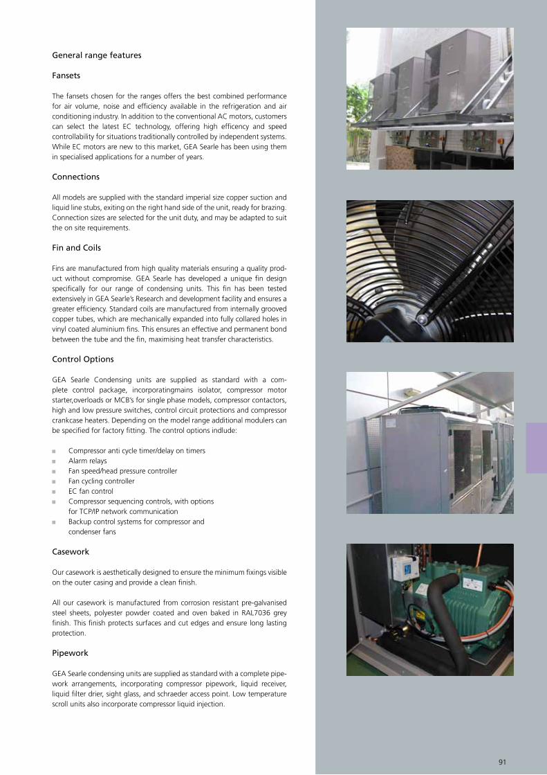
90 91
General range features
Fansets
The fansets chosen for the ranges offers the best combined performance for air volume, noise and efficiency available in the refrigeration and air conditioning industry. In addition to the conventional AC motors, customerscan select the latest EC technology, offering high efficency and speed controllability for situations traditionally controlled by independent systems. While EC motors are new to this market, GEA Searle has been using them in specialised applications for a number of years.
Connections
All models are supplied with the standard imperial size copper suction and liquid line stubs, exiting on the right hand side of the unit, ready for brazing.Connection sizes are selected for the unit duty, and may be adapted to suit the on site requirements.
Fin and Coils
Fins are manufactured from high quality materials ensuring a quality prod-uct without compromise. GEA Searle has developed a unique fin design specifically for our range of condensing units. This fin has been tested extensively in GEA Searle’s Research and development facility and ensures a greater efficiency. Standard coils are manufactured from internally grooved copper tubes, which are mechanically expanded into fully collared holes in vinyl coated aluminium fins. This ensures an effective and permanent bond between the tube and the fin, maximising heat transfer characteristics.
Control Options
GEA Searle Condensing units are supplied as standard with a com-plete control package, incorporatingmains isolator, compressor motor starter,overloads or MCB’s for single phase models, compressor contactors, high and low pressure switches, control circuit protections and compressor crankcase heaters. Depending on the model range additional modulers can be specified for factory fitting. The control options indlude:
Compressor anti cycle timer/delay on timers Alarm relays Fan speed/head pressure controller Fan cycling controller EC fan control Compressor sequencing controls, with options for TCP/IP network communication Backup control systems for compressor and condenser fans
Casework
Our casework is aesthetically designed to ensure the minimum fixings visible on the outer casing and provide a clean finish.
All our casework is manufactured from corrosion resistant pre-galvanised steel sheets, polyester powder coated and oven baked in RAL7036 grey finish. This finish protects surfaces and cut edges and ensure long lasting protection.
Pipework
GEA Searle condensing units are supplied as standard with a complete pipe-work arrangements, incorporating compressor pipework, liquid receiver, liquid filter drier, sight glass, and schraeder access point. Low temperature scroll units also incorporate compressor liquid injection.

Single, Twin and Multiple Compressor Condensing Units
Scroll, Reciprocating and Digital Compressor
Standard product range or configure to customer specification
High Specification
GEA Searle Condensing Units are supplied as standard with acomplete control package, incorporating:
Mains Isolator
Compressor Motor Starter/Overloads or MCB’s for single phase models
Compressor Contactors
High and Low pressure switches
Controls Circuit protection
Fitted pressure relief valve (PRV)
Compressor Crankcase Heaters. Depending on the model range additional control modules can be specified for factory fitting.
Quality Assured
Searle is a quality assured company to ISO 9001:2000 encom-passing performance testing, manufacturing systems and Inspection Procedures.
Backing our beliefs
We are so confident in our product that we offer two years warranty on all condensing units. (subject to standard Terms & Conditions of Sale and excluding corrosion through misap-plication).
92 93
GEA Searle - Condensing Units
Yes No Option Optimum Good Satisfactory
Mo
del
Co
mp
ress
or
typ
e
Co
mp
ress
o Q
uan
tity
Sin
gle
Ph
ase/
3 P
has
e
Co
nd
ense
r Fa
ns
Fearures
HCU2-3HT/LT
3ph
6pl/8pl
12pl/EC
NDQ
N2DQ
1
23ph 6pl/
EC
NBQ 1 6pl3ph
1 4pl
6pl/EC
1&3ph
NRE
NRQ
4pl
6pl1 1&3ph
N2CQ 2 3ph 6pl/EC
NSE
NSQ
Scroll
DigitalScroll
Recip
Scroll
Scroll
Recip
ScrollFa
n s
pee
d c
on
tro
ller
Aco
ust
ic In
sula
tio
n
Oil
sep
arat
or
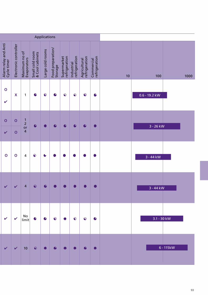
92 93
10 100 1000Elec
tro
nic
co
ntr
olle
r
Max
imu
m n
o o
fEv
apo
rato
rs
Sup
erm
arke
tre
frig
erat
ion
Applications
6 - 115kW
3.1 - 30 kW
3 - 44 kW
3 - 26 kW
0.6 - 19.2 kW
3 - 44 kW
1
Ala
rm r
elay
an
d A
nti
Cyc
le t
imer
Larg
e co
ld r
oo
ms
Foo
d p
rep
arat
ion
/St
ora
ge
Smal
l co
ld r
oo
m&
Co
ol c
abin
ets
Ind
ust
rial
re
frig
erat
ion
Ag
ricu
ltu
ral
refr
iger
atio
n
Co
mm
erci
al
refr
iger
atio
n
12or4
4
4
Nolimit
10

94 95
GEA Searle - NRE Condensing Unit
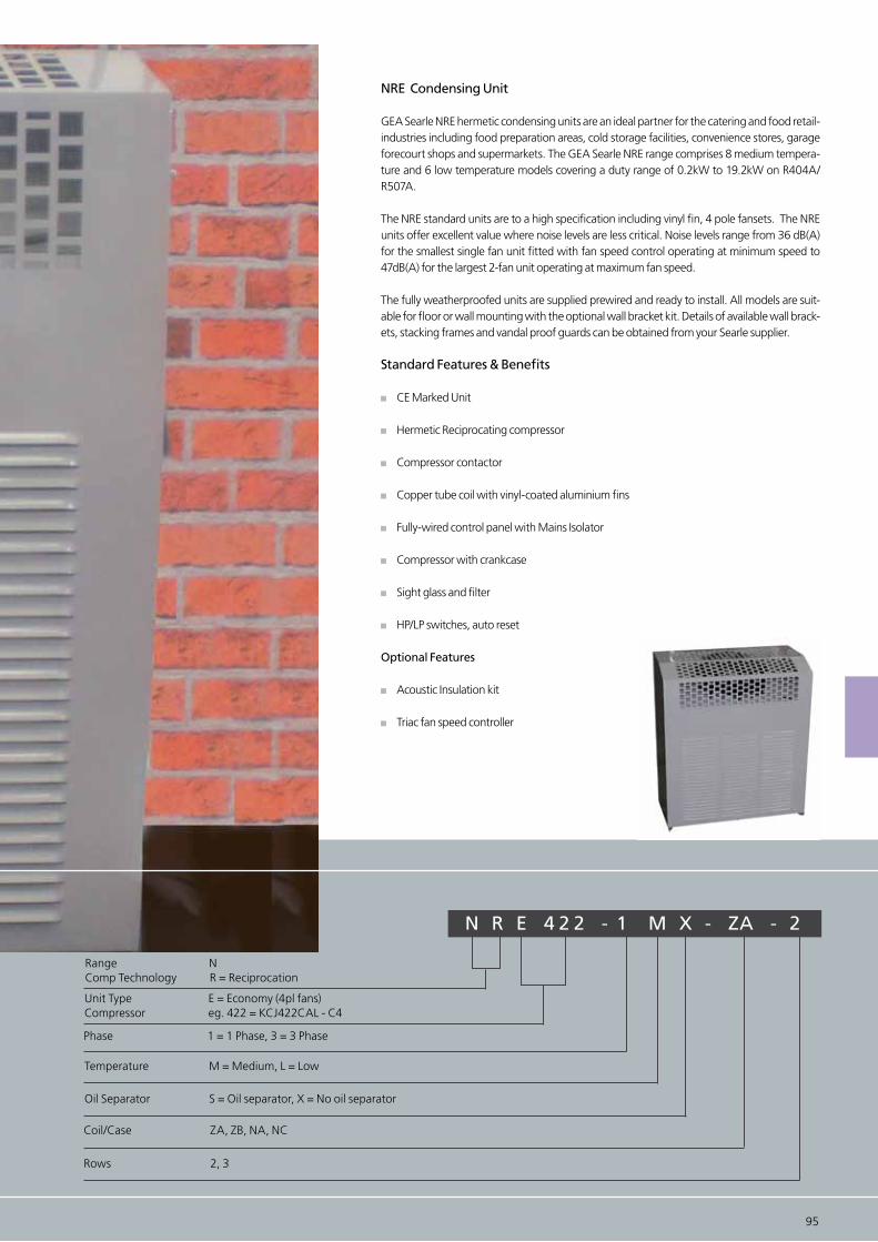
94 95
NRE Condensing Unit
GEA Searle NRE hermetic condensing units are an ideal partner for the catering and food retail-industries including food preparation areas, cold storage facilities, convenience stores, garage forecourt shops and supermarkets. The GEA Searle NRE range comprises 8 medium tempera-ture and 6 low temperature models covering a duty range of 0.2kW to 19.2kW on R404A/ R507A.
The NRE standard units are to a high specification including vinyl fin, 4 pole fansets. The NRE units offer excellent value where noise levels are less critical. Noise levels range from 36 dB(A) for the smallest single fan unit fitted with fan speed control operating at minimum speed to 47dB(A) for the largest 2-fan unit operating at maximum fan speed.
The fully weatherproofed units are supplied prewired and ready to install. All models are suit-able for floor or wall mounting with the optional wall bracket kit. Details of available wall brack-ets, stacking frames and vandal proof guards can be obtained from your Searle supplier.
Standard Features & Benefits
CE Marked Unit
Hermetic Reciprocating compressor
Compressor contactor
Copper tube coil with vinyl-coated aluminium fins
Fully-wired control panel with Mains Isolator
Compressor with crankcase
Sight glass and filter
HP/LP switches, auto reset
Optional Features
Acoustic Insulation kit
Triac fan speed controller
N R E 4 2 2 - 1 M X - ZA - 2
Range NComp Technology R = Reciprocation
Oil Separator S = Oil separator, X = No oil separator
Coil/Case ZA, ZB, NA, NC
Unit Type E = Economy (4pl fans)Compressor eg. 422 = KCJ422CAL - C4
Phase 1 = 1 Phase, 3 = 3 Phase
Rows 2, 3
Temperature M = Medium, L = Low
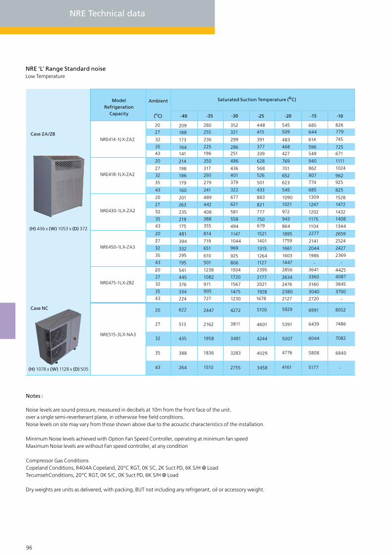
96 97
NRE ‘L’ Range Standard noiseLow Temperature
20
27
32
-10-15-20-25-30-35-40
3543
20
27
32
35
43
20
27
32
35
43
20
(oC)
Saturated Suction Temperature (oC)ModelRefrigeration
Capacity
Ambient
355
27
32
35
43 501
NRE414-1LX-ZA2
NRE418-1LX-ZA2
NRE430-1LX-ZA2
NRE450-1LX-ZA3
NRE475-1LX-ZB2
NRE515-3LX-NA3
20
27
32
35
NRE Technical data
43
20
27
32
35
43
209
188
173
164141
214
198
186
179
160
201
263
235
219
175
481
394
332295
195
622
513
435
388
264
541
445
376
334
224
280
255
236
225196
350
317
293
279
241
489
442
408
388
814
719
651
610
2447
2162
1958
1836
1510
1238
1082
971
905
727
352
321
299
286251
486
436
401
379
322
677
621
581
558
494
1147
1044
969
925
806
4272
3811
3481
3283
2755
1934
1720
1567
1475
1230
448415
391
377
339
628
568
526
501
433
883
821
777
750679
1521
1401
1315
12641127
5100
4601
4244
4029
3458
2395
2177
2021
19281678
545509
483
468427
769
701
652
623
545
10901021
972
943
864
1759
1661
1603
1447
1895
5929
5391
5007
4776
4161
2856
2634
2476
2380
2127
685644
614
596549
940
862
807
774
685
1309
1247
1202
1175
1104
2277
2141
2044
1986
-
6991
6439
6044
5808
5177
3641
3360
3160
3040
2720
826779
745
725671
1111
1024
962925
825
1528
1472
1432
1408
1344
2659
2524
2427
2369
-
8052
7486
7082
6840
-
44254087
3845
3700
-
Notes :
Noise levels are sound pressure, measured in decibels at 10m from the front face of the unit.over a single semi-reverberant plane, in otherwise free field conditions.Noise levels on site may vary from those shown above due to the acoustic characteristics of the installation.
Minimum Noise levels achieved with Option Fan Speed Controller, operating at minimum fan speedMaximum Noise levels are without Fan speed controller, at any condition
Compressor Gas ConditionsCopeland Conditions, R404A Copeland, 20°C RGT, 0K SC, 2K Suct PD, 6K S/H @ LoadTecumsehConditions, 20°C RGT, 0K S/C, 0K Suct PD, 6K S/H @ Load
Dry weights are units as delivered, with packing, BUT not including any refrigerant, oil or accessory weight.
Case ZA/ZB
(H) 436 x (W) 1053 x (D) 372
Case NC
(H) 1078 x (W) 1128 x (D) 505

96 97
FLC LRA
(A) (A)
Compressor
FLC LRA
(A) (A) inches inches (L) (kg)
DryWeight
Max* Min*
dB(A)*
Sound Levels
1/2”
1/2”
5/8”
5/8”
2.60
2.60
2.60
2.60
5/8” 2.60
16.0
14.0
30.0
50.0
72.0
45.0
ZA
ZA
ZA
ZA
ZB
NC
1 x 254
1 x 254
1 x 254
1 x 254
1 x 315
1 x 400
0.6
0.6
0.6
0.6
0.5
1.0
1.7
1.7
1.7
1.7
1.5
2.1
3/8”
3/8”
3/8”
3/8”
3/8”
3/8” 7/8” 2.40
55
56
67
71
79
111
40
40
40
40
42
47
36
36
36
36
37
43
LiquidSuction
CaseSize
DrawingNumber of Fans and Diameter
Connection Sizes LiquidReceiver
Fansets (230V/1ph/50Hz)
3.5
5.8
6.6
3.4
13.0
8.0
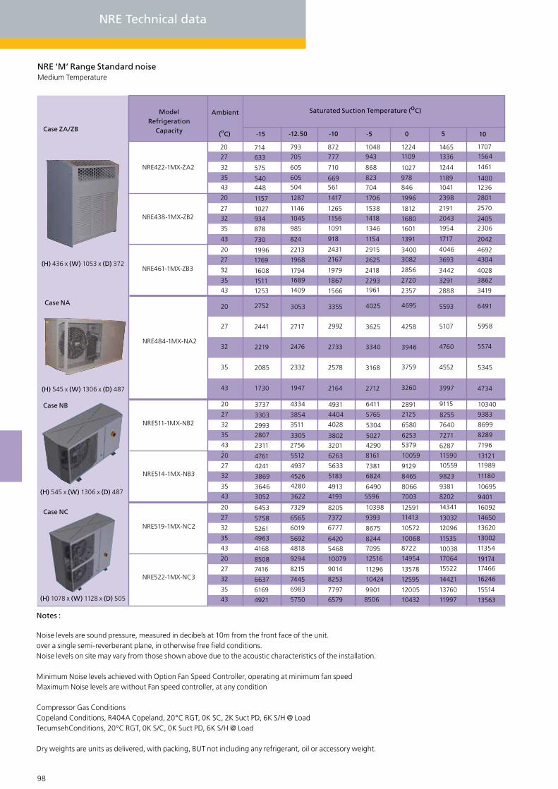
20
27
32
35
43
NRE511-1MX-NB2
NRE514-1MX-NB3
20
27
32
35
43
3737
3303
29932807
2311
4761
4241
3869
3646
3052
4931
4404
4028
3802
3201
6263
5633
5183
4913
4193
6411
5765
5304
50274290
8161
7381
6824
64905596
2125
6580
6253
5379
2891
10059
9129
8465
8066
7003
9115
8255
7640
7271
628711590
10559
9823
9381
8202
10340
9383
8699
8289
7196
1312111989
11180
10695
9401
98 99
NRE ‘M’ Range Standard noiseMedium Temperature
20
27
32
1050-5-10-12.50-15
3543
20
27
32
35
43
20
27
32
35
43
20
(oC)
Saturated Suction Temperature (oC)ModelRefrigeration
Capacity
Ambient
27
32
35
43
NRE422-1MX-ZA2
NRE438-1MX-ZB2
NRE461-1MX-ZB3
NRE519-1MX-NC2
NRE522-1MX-NC3
NRE484-1MX-NA2
20
27
32
35
43
20
27
32
35
43
714
633
575
540448
1157
1027
934
878
730
1996
1769
1608
1511
1253
6453
5758
52614963
4168
2752
2441
2219
2085
1730
8508
7416
6637
6169
4921
2756
4334
3854
3511
3305
5512
4937
4526
4280
3622
1409
4818
793
705
605
605504
1287
1146
1045
985
824
2213
1968
17941689
7329
6565
6019
5692
3053
2717
2476
2332
1947
9294
8215
7445
6983
5750
872
777
710
669561
1417
1265
1156
1091
918
2431
2167
1979
1867
1566
8205
7372
6777
6420
5468
3355
2992
2733
2578
2164
10079
9014
8253
7797
6579
1048943
868
823
704
1706
1538
1418
1346
1154
2915
2625
2418
22931961
10398
9393
8675
82447095
4025
3625
3340
3168
2712
12516
11296
10424
99018506
12241109
1027
978846
1996
1812
1680
1601
1391
34003082
2856
2720
2357
11413
10572
10068
8722
12591
4695
4258
3946
3759
3260
14954
13578
12595
12005
10432
14651336
1244
11891041
2398
2191
2043
1954
1717
4046
3693
3442
3291
2888
14341
13032
12096
11535
10038
5593
5107
4760
4552
3997
17064
15522
14421
13760
11997
17071564
1461
14001236
2801
2570
24052306
2042
4692
4304
4028
3862
3419
16092
14650
13620
13002
11354
6491
5958
5574
5345
4734
1917417466
16246
15514
13563
Notes :
Noise levels are sound pressure, measured in decibels at 10m from the front face of the unit.over a single semi-reverberant plane, in otherwise free field conditions.Noise levels on site may vary from those shown above due to the acoustic characteristics of the installation.
Minimum Noise levels achieved with Option Fan Speed Controller, operating at minimum fan speedMaximum Noise levels are without Fan speed controller, at any condition
Compressor Gas ConditionsCopeland Conditions, R404A Copeland, 20°C RGT, 0K SC, 2K Suct PD, 6K S/H @ LoadTecumsehConditions, 20°C RGT, 0K S/C, 0K Suct PD, 6K S/H @ Load
Dry weights are units as delivered, with packing, BUT not including any refrigerant, oil or accessory weight.
NRE Technical data
Case ZA/ZB
(H) 436 x (W) 1053 x (D) 372
Case NC
(H) 1078 x (W) 1128 x (D) 505
Case NB
(H) 545 x (W) 1306 x (D) 487
Case NA
(H) 545 x (W) 1306 x (D) 487

98 99
FLC LRA
(A) (A)
Compressor
FLC LRA
(A) (A) inches inches (L) (kg)
DryWeight
Max* Min*
dB(A)*
Sound Levels
1/2”
1/2”
5/8”
5/8”
2.6
2.6
2.6
2.6
7/8” 6.4
16.0
24.0
25.0
37.0
75.0
104.0
ZA
ZB
ZB
NA
NB
NC
1 x 254
1 x 315
1 x 2315
1 x 400
1 x 450
1 x 400
0.6
0.5
0.5
1.0
1.6
2.0
1.7
1.5
1.5
2.1
3.5
4.2
3/8”
3/8”
3/8”
3/8”
1/2”
1/2” 7/8” 6.4
64
69
70
99
125
146
40
42
42
47
48
50
36
37
37
43
43
46
LiquidSuction
CaseSize
DrawingNumber of Fans and Diameter
Connection Sizes LiquidReceiver
Fansets (230V/1ph/50Hz)
5.0
6.0
11.5
3.4
13.5
19.0
85.0 NC 1 x 400 2.0 4.2 1/2” 7/8” 6.4 141 50 4617.0
7/8” 6.454.0 NB 1 x 450 1.6 3.5 1/2” 113 48 439.5
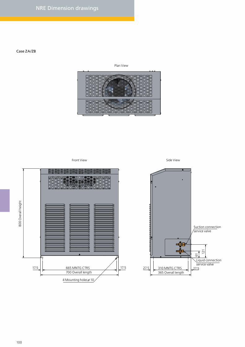
NRE Dimension drawings
Case ZA/ZB
Plan View
Front View Side View
800
Ove
rall
heig
ht
17.5 665 MNTG CTRS700 Overall length
4 Mounting holes 10
17.5 310 MNTG CTRS365 Overall length
27.527.5
Liquid connectionservice valve
Suction connectionservice valve
121
61
100 101

100 101
Knock out inbase for customer electrical supply
Knock out inbase for customer electrical supply
Site glass viewing port
Knock out in rear panel of uint for customer
electrical supply
Case NB & NC
Case NB Front View and End view
749 Mounting centres
505
Ove
rall
wid
th47
5 M
ount
ing
cent
res
196
Suction connection Liquid connection
View of connection details on rear of unit
36138
672
Ove
r all
hieg
ht
184
1128 Overall length
Door inter locked isolator
460 Overall length
505
80
161
58
Case NC Front View and End view
1078
Ove
r all
hieg
ht
1128 Overall length
Door inter locked isolator
460 Overall length
505
80
161
59

102 103
GEA Searle - NSE/NSQ Condensing Unit
1. Vinyl coated aluminium coil as standard
2. Condenser fanset
3. Motor starter
4. Compressor contactor
5. LP switch
6. Anti recycle timer alarm relay
7. Acoustic insulation
8. Compressor
1
2
5
4
3
6
7
8

102 103
NSE - NSQ Single Scroll Condensing unit
GEA Searle NSE - NSQ scroll condensing units are an ideal partner for the catering and food retail industries including food preparation areas, cold storage facilities, convenience stores, garage forecourt shops and supermarkets. The GEA Searle NSE - NSQ range comprises eleven medium temperature and nine low temperature base models covering a duty range of 1.5kW to 47kW on R404A/ R507 and R407C. Different options are available for each base unit to match the condenser and fanset selection to exact requirements.
The NSQ standard units are to a high specification including vinyl fin, 6 pole fansets and acous-tic insulation. The NSE units offer excellent value where noise levels are less critical. Noise levels range from 28 dB(A) for the smallest single fan unit fitted with fan speed control operating at minimum speed to 56 dB(A) for the largest four-fan unit operating at maximum fan speed. The fully weatherproofed units are supplied prewired and ready to install. All models are suitable for floor or wall mounting with the optional wall bracket kit.
The smaller capacity units may be wall mounted or, where floor space is at a premium, double stacked. Details of available wall brackets, stacking frames and vandal proof guards can be obtained from your Searle supplier.
Standard Features & Benefits
CE Marked Unit, Compliant scroll compressor, Compressor motor starter with short cir-cuit and overload protection, Compressor contactor, Copper tube coil with vinyl-coated aluminium fins, Fully-wired control panel with Mains Isolator, Compressor with cran-case heater, Sight glass and filter, HP/LP switches auto reset.
Options
Pressure activated fan speed control kit*, Start delay and anti-recycle timer* Volt-free contact for alarm signal*, Acoustic Insulation Kit*
* included as standard on NSQ models
Oil separator, EC Fans and controller, Wall bracket, Vandal Proof Cage, Con-denser coils with copper fin.
N S Q 45 - 3 M X - C 3 F I - V O
Range NComp Technology S = Scroll
Unit Type Q = Quiet (6pl fans), E = Economy (4pl fans)Compressor eg. 45 = ZB45, 18 = ZF18
Opitional Extras O = Evaporator contactor, S = Solenoid valve, G = Evap. Contactor + Sol. valve
Phase 1 = 1 Phase, 3 = 3 PhaseTemperature M = Medium, L = Low
Oil separator S = Oil separator, X = N0 oil separator, V = EVI CompressorCoil/Case A, B, C, D, E
Rows 2,3Control package F = Fan speed controller, W = Fan speed controller + Anti cycle timer + Alarm relay T = Anti cycle timer + Alarm relay, E = Electronic Controller + EC FansAcoustic insulation I = InsulationFin material C = Copper, V = Vinyl coated aluminium
Standard specification Option

104 105
NSE - NCE Single scroll condensing unit
NSE ‘L’ Range Standard noiseLow Temperature
27
32
35
-10-15-20-25-30-35-40
4327
32
35
43
27
32
35
43
27
32
35
43
(oC)
Saturated Suction Temperature (oC)Model Ambient
3130
27
32
35
43 3346
NSE9-3LX-A
NSE11-3LX-A
NSE13-3LX-A
NSE15-3LX-A
NSE18-3LX-A
1663
1560
1498
13342074
1936
1854
1633
2322
2190
2110
1899
2801
2611
2497
2194
3448
32113068
2688
2119
1985
1904
16902620
2445
2340
2060
2956
2760
2643
2329
3520
3276
2739
4316
4013
3831
2574
2409
2310
20463167
2955
2827
2487
3591
3331
3175
2760
4240
3941
3762
-
5183
4815
4594
-
31492940
2815
2481
3827
3566
3409
2992
4358
4035
3841
3323
5106
47244494
-
6256
5800
5527 -
37243471
3320
29164486
4177
3992
3498
5126
4738
45063887
5972
5506
5227
7330
6786
6460
-
-
44624157
3974
34875327
4954
4730
4133
6055
5606
5337
4618
6980
6430
6099
-
8601
7953
7564
-
51994843
4629
40596168
5730
5468
47676984
6473
6167
5350
7987
7353
6972
-
9871
9120
8669
-
NCE ‘L’ Range Standard noiseLow Temperature
27
32
35
43
27
32
35
43
27
32
35
43
7938
27
32
35
43 -
NCE24-3LX-D
NCE33-3LX-D
NCE40-3LX-D
NCE48-3LX-D
4375
4062
3875
3374
5211
4877
4676
4140
7080
6574
6270
5461
7763
71646805
5847
5592
5213
4986
4379
7158
6652
6349
5539
8962
8322
6914
9916
9119
8642
6810
6364
6096
5383
9105
8428
8021
6938
10843
10069
9605
-
12068
11075
10478
-
8318
7764
7431
6545
11074
10236
9734
8393
13025
1206711493
-
14356
13155
12434 -
9826
9164
8766
7707
13044
12045
114469847
15206
14065
13380
16644
15235
14390
-
-
11713
10905
10420
9127
15263
14114
13424
11585
17748
16386
15568
-
19198
17596
16634
-
13601
12646
12074
1054717481
16182
15402
13323
20289
18707
17757
-
21753
19956
18879
-
Performance data in Watts rated at 20oC Return Gas Temperature, 0K Sub Cooling
Case A
(H) 570 x (W) 1128 x (D) 505
Case D
(H) 1192 x (W) 1160 x (D) 600

104 105
FLC LRA
(A) (A)
Compressor
FLC LRA
(A) (A) inches inches (L) (kg)
DryWeight
Max* Min*
dB(A)*
Sound Levels
3/8”
3/8”
3/8”
1/2”
6.2
6.2
6.2
6.2
40
46
52
74
A
A
A
A
1 x 400 4pl
1 x 400 4pl
1 x 400 4pl
1 x 400 4pl
1.0
1.0
1.0
1.0
2.12
2.12
2.12
2.12
7/8”
7/8”
7/8”
7/8”
123
124
134
141
48
48
48
48
43
43
43
44
LiquidSuction
CaseSize
DrawingNumber of Fans and Diameter
Connection Sizes LiquidReceiver
Fansets (230V/1ph/50Hz)
7.0
8.0
12.0
6.0
3/8” 6.264 A 1 x 400 4pl 1.0 2.12 7/8” 135 48 4410.0
5/8”
5/8”
5/8”
18.0
18.0
18.0
99
134
187
A
A
A
2 x 450 4pl
2 x 450 4pl
2 x 450 4pl
3.1
3.1
3.1
6.9
6.9
6.9
1 1/8”
1 1/8”
1 5/8”
161
162
191
53
53
53
46
46
46
16.1
23.0
30.6
5/8” 18.0159 A 2 x 450 4pl 3.1 6.9 1 1/8” 182 53 4626.0
* Noise levels in dB(A) at 10m from the front face of the unit, min. noise levels with fan speed control at minimum speed
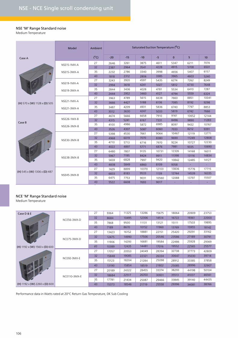
106 107
NSE - NCE Single scroll condensing unit
NSE ‘M’ Range Standard noiseMedium Temperature
27
32
35
1050-5-10-15-20
4327
32
35
43
27
32
35
43
27
32
35
43
(oC)
Saturated Suction Temperature (oC)Model Ambient
4986
27
32
35
43 4897
NSE15-1MX-A
NSE19-1MX-A
NSE21-1MX-A
NSE26-1MX-B
NSE30-3MX-B
2646
2387
2232
18183243
2994
2844
2444
3963
3666
3487
3012
4674
4315
4100
3526
5398
49684710
4022
3261
2964
2786
23123920
3618
3436
2952
4789
4427
4209
3630
5666
5241
4307
4530
6019
5713
3875
3541
3340
28064597
4241
4028
3460
5615
5188
4931
4247
6658
6167
5872
5087
7661
7070
6716
5771
46114228
3998
3385
5435
5027
4781
4127
6638
6136
5836
5033
7910
73316985
6060
9064
8380
79706876
53474915
4656
39656274
5812
5534
4794
7660
7085
67405819
9161
8496
8097
10467
9690
9224
7981
7033
62115708
5407
46037262
6730
6410
5559
8851
8192
7797
6742
10652
9890
9432
8212
12119
11249
10727
9335
70746501
6157
52408249
7648
7287
632410041
9298
8853
7666
12144
11283
10767
9391
13771
12808
12230
10690
27
32
35
43
6828
27
32
35
43 6608
NSE38-3MX-B
NSE45-3MX-B
6480
5967
5659
4838
7429
68336475
5522
7807
7195
5849
8899
8183
7753
9135
8424
7997
6860
10370
9533
9031
7693
10731
99119420
8109
12103
1139
105609017
12326
11398
10842
13836
12744
12088
-
9358
14168
13116
12485
-
15776
14539
13797
-
16011
14834
14127
-
17715
16335
15507
-
NSE15-3MX-A
NSE19-3MX-A
NSE21-3MX-A
NSE26-3MX-B
NCE ‘M’ Range Standard noiseMedium Temperature
27
32
35
43
27
32
35
43
27
32
35
43
27
32
35
43
NCE56-3MX-D
NCE75-3MX-D
NCE92-3MX-E
NCE110-3MX-E
9364
8684
7868
7189
13423
12475
11906
10389
17057
15848
15123
13190
20189
18684
17781
15373
18204
18546
11325
10495
9500
8670
16152
14990
14293
12435
20553
19085
15854
24322
22517
21434
13286
12306
11131
10152
18881
17506
16681
14481
24049
22321
21284
18519
28455
26350
25087
21719
15675
14514
13121
11960
22151
20546
19584
17016
28394
26334
25098
21802
33374
30931
29466
25558
18064
16722
15111
13769
25420
23586
22486
19552
32738
30647
28912
38293
35513
33845
29396
25085
20909
19361
17503
15955
29291
27189
25928
22565
37773
35030
33385
28996
44198
41037
39140
34081
23753
22000
19895
18142
33162
30791
29369
25577
42809
39714
37858
32907
50104
46561
44435
38766
Performance data in Watts rated at 20oC Return Gas Temperature, 0K Sub Cooling
Case A
(H) 570 x (W) 1128 x (D) 505
Case B
(H) 545 x (W) 1306 x (D) 487
Case D & E
(H) 1192 x (W) 1560 x (D) 600
(H) 1192 x (W) 2260 x (D) 600
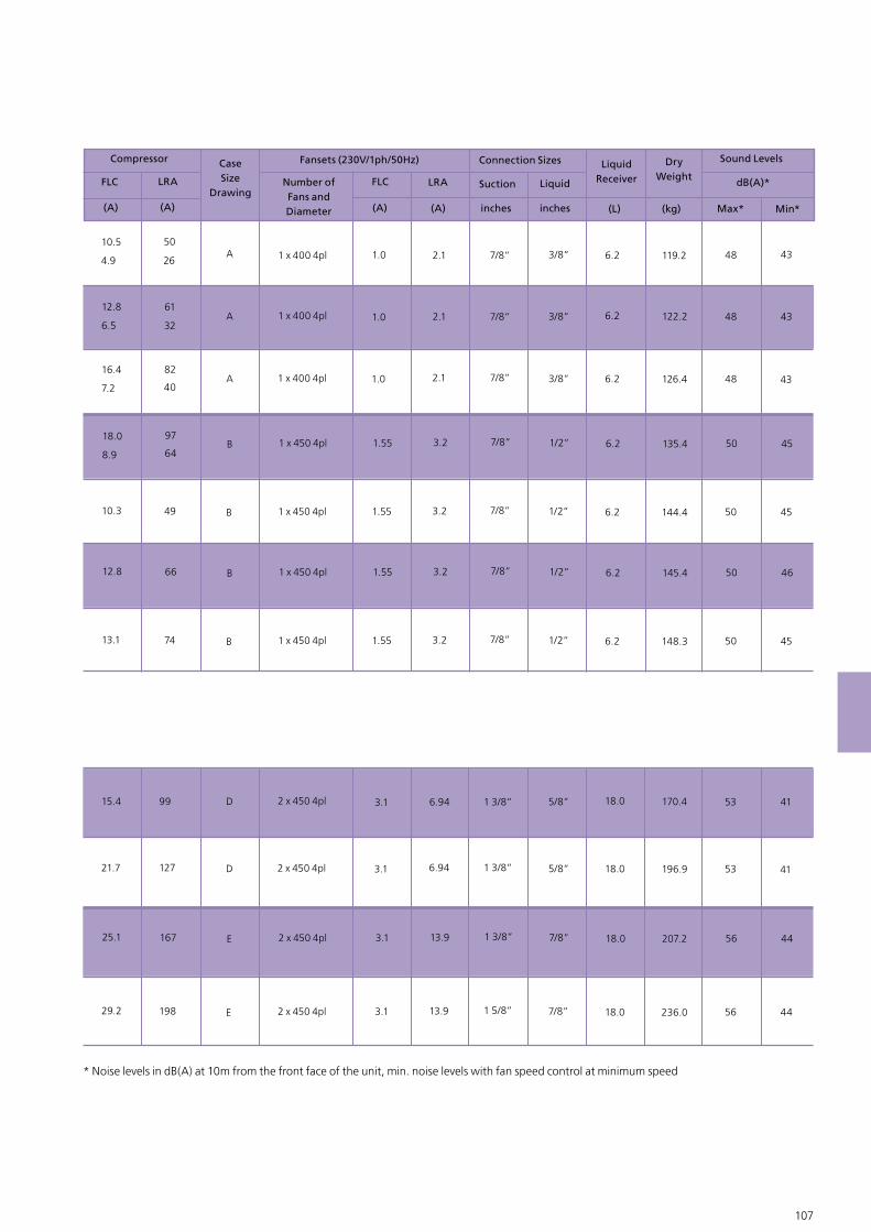
106 107
FLC LRA
(A) (A)
Compressor
FLC LRA
(A) (A) inches inches (L) (kg)
DryWeight
Max* Min*
dB(A)*
Sound Levels
3/8”
3/8”
3/8”
1/2”
6.2
6.2
6.2
6.2
50
61
82
49
A
A
A
B
1 x 400 4pl
1 x 400 4pl
1 x 400 4pl
1 x 450 4pl
1.0
1.0
1.0
1.55
2.1
2.1
2.1
3.2
7/8”
7/8”
7/8”
7/8”
119.2
122.2
126.4
144.4
48
48
48
50
43
43
43
45
LiquidSuction
CaseSize
DrawingNumber of Fans and Diameter
Connection Sizes LiquidReceiver
Fansets (230V/1ph/50Hz)
12.8
16.4
10.3
10.5
1/2” 6.297
B 1 x 450 4pl 1.55 3.2 7/8” 135.4 50 4518.0
1/2” 6.274 B 1 x 450 4pl 1.55 3.2 7/8” 148.3 50 4513.1
1/2” 6.266 B 1 x 450 4pl 1.55 3.2 7/8” 145.4 50 4612.8
5/8”
5/8”
7/8”
18.0
18.0
18.0
99
127
198
D
D
E
2 x 450 4pl
2 x 450 4pl
2 x 450 4pl
3.1
3.1
3.1
6.94
6.94
13.9
1 3/8”
1 3/8”
1 5/8”
170.4
196.9
236.0
53
53
56
41
41
44
15.4
21.7
29.2
7/8” 18.0167 E 2 x 450 4pl 3.1 13.9 1 3/8” 207.2 56 4425.1
* Noise levels in dB(A) at 10m from the front face of the unit, min. noise levels with fan speed control at minimum speed
6.5
7.2
4.9
8.9
26
32
40
64
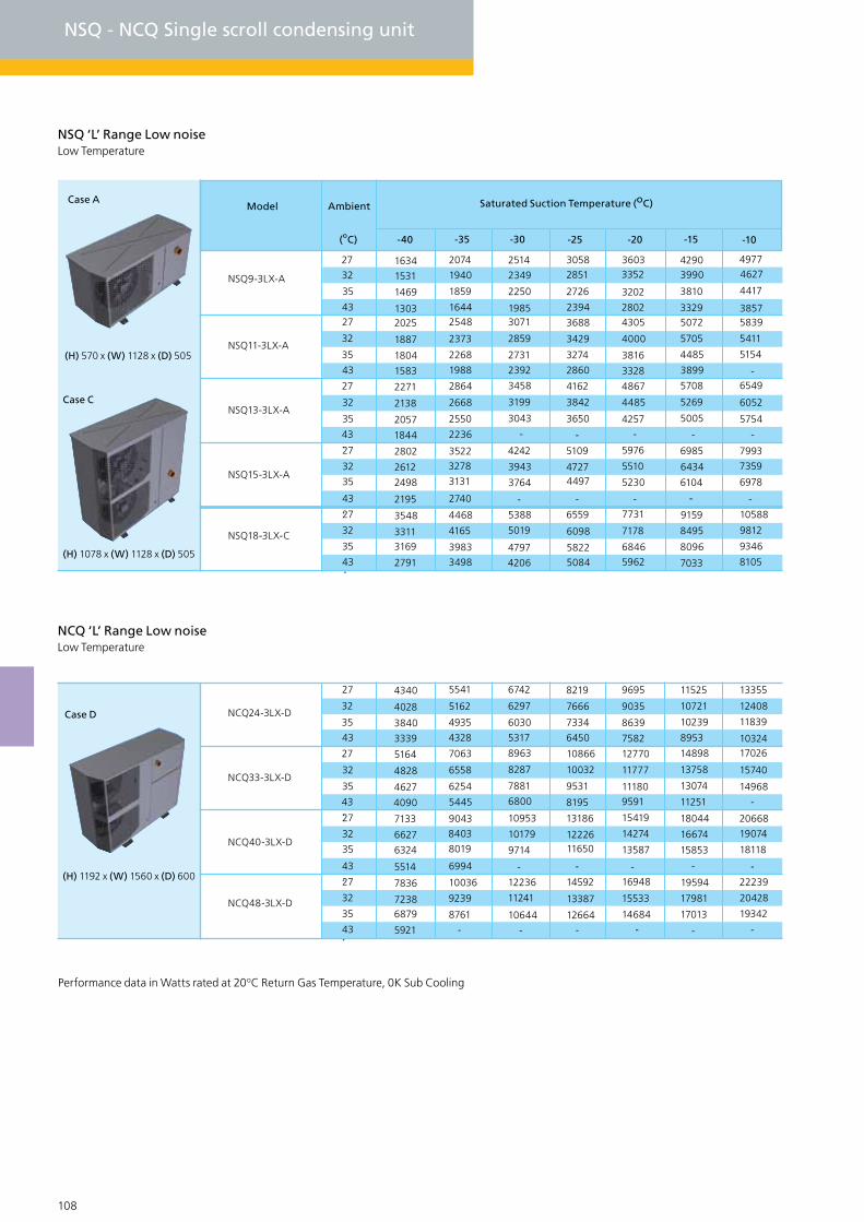
108 109
NSQ - NCQ Single scroll condensing unit
NSQ ‘L’ Range Low noiseLow Temperature
27
32
35
-10-15-20-25-30-35-40
4327
32
35
43
27
32
35
43
27
32
35
43
(oC)
Saturated Suction Temperature (oC)Model Ambient
3131
27
32
35
43 3498
NSQ9-3LX-A
NSQ11-3LX-A
NSQ13-3LX-A
NSQ15-3LX-A
NSQ18-3LX-C
1634
1531
1469
13032025
1887
1804
1583
2271
2138
2057
1844
2802
2612
2498
2195
3548
33113169
2791
2074
1940
1859
16442548
2373
2268
1988
2864
2668
2550
2236
3522
3278
2740
4468
4165
3983
2514
2349
2250
19853071
2859
2731
2392
3458
3199
3043
-
4242
3943
3764
-
5388
5019
4797
4206
30582851
2726
2394
3688
3429
3274
2860
4162
3842
3650
-
5109
47274497
-
6559
6098
58225084
36033352
3202
28024305
4000
3816
3328
4867
4485
4257 -
5976
5510
5230
7731
7178
6846
5962
-
42903990
3810
33295072
5705
4485
3899
5708
5269
5005
-
6985
6434
6104
-
9159
8495
8096
7033
49774627
4417
38575839
5411
5154
-6549
6052
5754
-
7993
7359
6978
-
10588
9812
9346
8105
NCQ ‘L’ Range Low noiseLow Temperature
27
32
35
43
27
32
35
43
27
32
35
43
8019
27
32
35
43 -
NCQ24-3LX-D
NCQ33-3LX-D
NCQ40-3LX-D
NCQ48-3LX-D
4340
4028
3840
3339
5164
4828
4627
4090
7133
6627
6324
5514
7836
72386879
5921
5541
5162
4935
4328
7063
6558
6254
5445
9043
8403
6994
10036
9239
8761
6742
6297
6030
5317
8963
8287
7881
6800
10953
10179
9714
-
12236
11241
10644
-
8219
7666
7334
6450
10866
10032
9531
8195
13186
1222611650
-
14592
13387
12664 -
9695
9035
8639
7582
12770
11777
111809591
15419
14274
13587
16948
15533
14684
-
-
11525
10721
10239
8953
14898
13758
13074
11251
18044
16674
15853
-
19594
17981
17013
-
13355
12408
11839
1032417026
15740
14968
-
20668
19074
18118
-
22239
20428
19342
-
Performance data in Watts rated at 20oC Return Gas Temperature, 0K Sub Cooling
Case A
Case C
(H) 1078 x (W) 1128 x (D) 505
(H) 570 x (W) 1128 x (D) 505
Case D
(H) 1192 x (W) 1560 x (D) 600
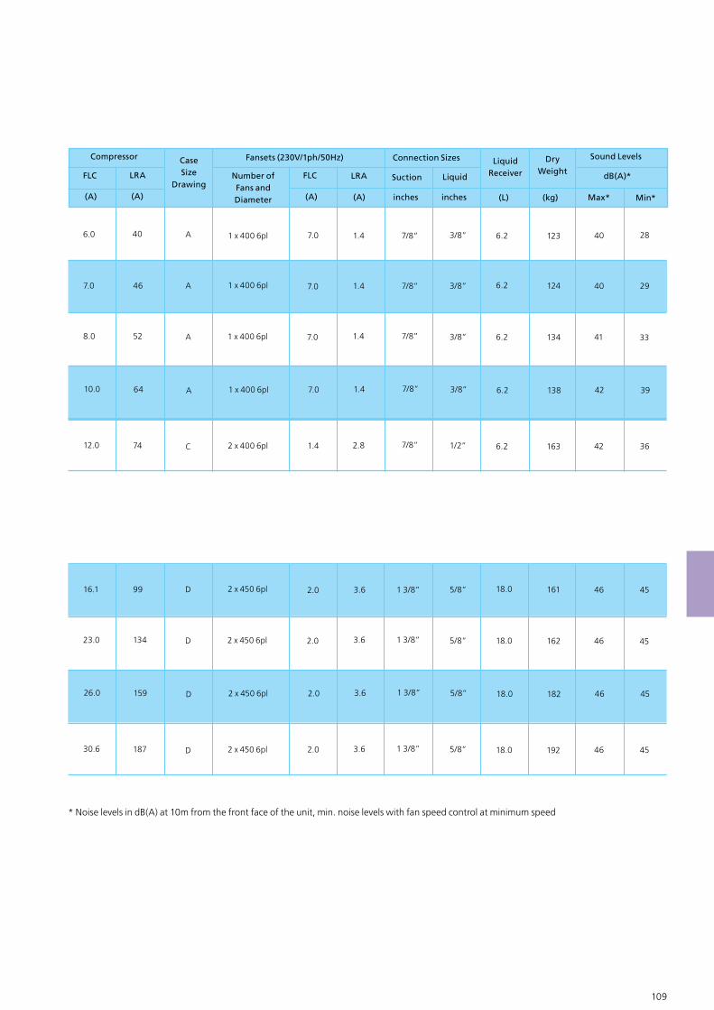
108 109
FLC LRA
(A) (A)
Compressor
FLC LRA
(A) (A) inches inches (L) (kg)
DryWeight
Max* Min*
dB(A)*
Sound Levels
3/8”
3/8”
3/8”
1/2”
6.2
6.2
6.2
6.2
40
46
52
74
A
A
A
C
1 x 400 6pl
1 x 400 6pl
1 x 400 6pl
2 x 400 6pl
7.0
7.0
7.0
1.4
1.4
1.4
1.4
2.8
7/8”
7/8”
7/8”
7/8”
123
124
134
163
40
40
41
42
28
29
33
36
LiquidSuction
CaseSize
DrawingNumber of Fans and Diameter
Connection Sizes LiquidReceiver
Fansets (230V/1ph/50Hz)
7.0
8.0
12.0
6.0
3/8” 6.264 A 1 x 400 6pl 7.0 1.4 7/8” 138 42 3910.0
5/8”
5/8”
5/8”
18.0
18.0
18.0
99
134
187
D
D
D
2 x 450 6pl
2 x 450 6pl
2 x 450 6pl
2.0
2.0
2.0
3.6
3.6
3.6
1 3/8”
1 3/8”
1 3/8”
161
162
192
46
46
46
45
45
45
16.1
23.0
30.6
5/8” 18.0159 D 2 x 450 6pl 2.0 3.6 1 3/8” 182 46 4526.0
* Noise levels in dB(A) at 10m from the front face of the unit, min. noise levels with fan speed control at minimum speed
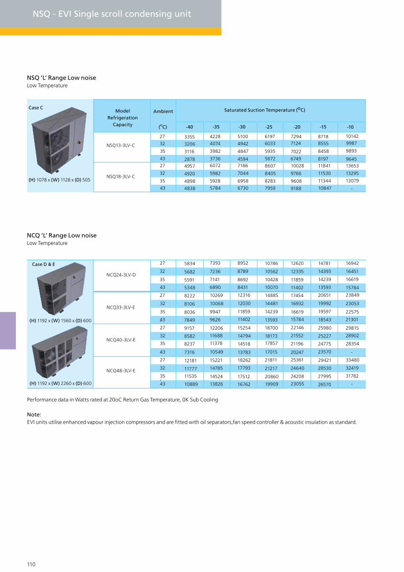
110 111
NSQ - EVI Single scroll condensing unit
NSQ ‘L’ Range Low noiseLow Temperature
27
32
35
-10-15-20-25-30-35-40
4327
32
35
43
(oC)
Saturated Suction Temperature (oC)ModelRefrigeration
Capacity
Ambient
NSQ13-3LV-C
NSQ18-3LV-C
3355
3206
3116
28784957
4920
4898
4838
4228
4074
3982
37366072
5982
5928
5784
5100
4942
4847
45947186
7044
6958
6730
61976033
5935
5672
8607
8405
8283
7959
72947124
7022
674910028
9766
9608
9188
87188555
8458
819711841
11530
11344
10847
101429987
9893
964513653
13295
13079
-
NCQ ‘L’ Range Low noiseLow Temperature
27
32
35
43
27
32
35
43
27
32
35
43
11378
27
32
35
43 13826
NCQ24-3LV-D
NCQ33-3LV-E
NCQ40-3LV-E
NCQ48-3LV-E
5834
5682
5591
5348
8222
8106
8036
7849
9157
8582
8237
7316
12181
11777
11535
10889
7393
7236
7141
6890
10269
10068
9947
9626
12206
11688
10549
15221
14785
14524
8952
8789
8692
8431
12316
12030
11859
11402
15254
14794
14518
13783
18262
17793
17512
16762
10786
10562
10428
10070
14885
14481
14239
13593
18700
18173
17857
17015
21811
21217
20860
19909
12620
12335
11859
11402
17454
16932
16619
15784
22146
21552
21196
25361
24640
24208
23055
20247
14781
14393
14239
13593
20651
19992
19597
18543
25980
25227
24775
23570
29421
28530
27995
26570
16942
16451
16619
15784
23849
23053
22575
21301
29815
28902
28354
-
33480
32419
31782
-
Performance data in Watts rated at 20oC Return Gas Temperature, 0K Sub Cooling
Note:EVI units utilise enhanced vapour injection compressors and are fitted with oil separators,fan speed controller & acoustic insulation as standard.
Case D & E
(H) 1192 x (W) 1560 x (D) 600
(H) 1192 x (W) 2260 x (D) 600
Case C
(H) 1078 x (W) 1128 x (D) 505

110 111
FLC LRA
(A) (A)
Compressor
FLC LRA
(A) (A) inches inches (L) (kg)
DryWeight
Max* Min*
dB(A)*
Sound Levels
1/2”
1/2”
6.2
6.2
51.5
74
C
C
2 x 400 6pl
2 x 400 6pl
1.4
1.4
2.8
2.8
7/8”
7/8”
168
174
42
42
36
36
LiquidSuction
CaseSize
DrawingNumber of Fans and Diameter
Connection Sizes LiquidReceiver
Fansets (230V/1ph/50Hz)
12.0
8.0
5/8”
7/8”
7/8”
18.0
18.0
18.0
99
127
198
D
E
E
2 x 450 6pl
2 x 450 6pl
2 x 450 6pl
2.0
4.0
4.0
3.5
7.2
7.2
1 3/8”
1 3/8”
1 5/8”
179
208
247
46
47
47
45
45
45
16.1
22.3
30.6
7/8” 18.0167 E 2 x 450 6pl 4.0 7.2 1 3/8” 218 47 4525.1
* Noise levels in dB(A) at 10m from the front face of the unit, min. noise levels with fan speed control at minimum speed
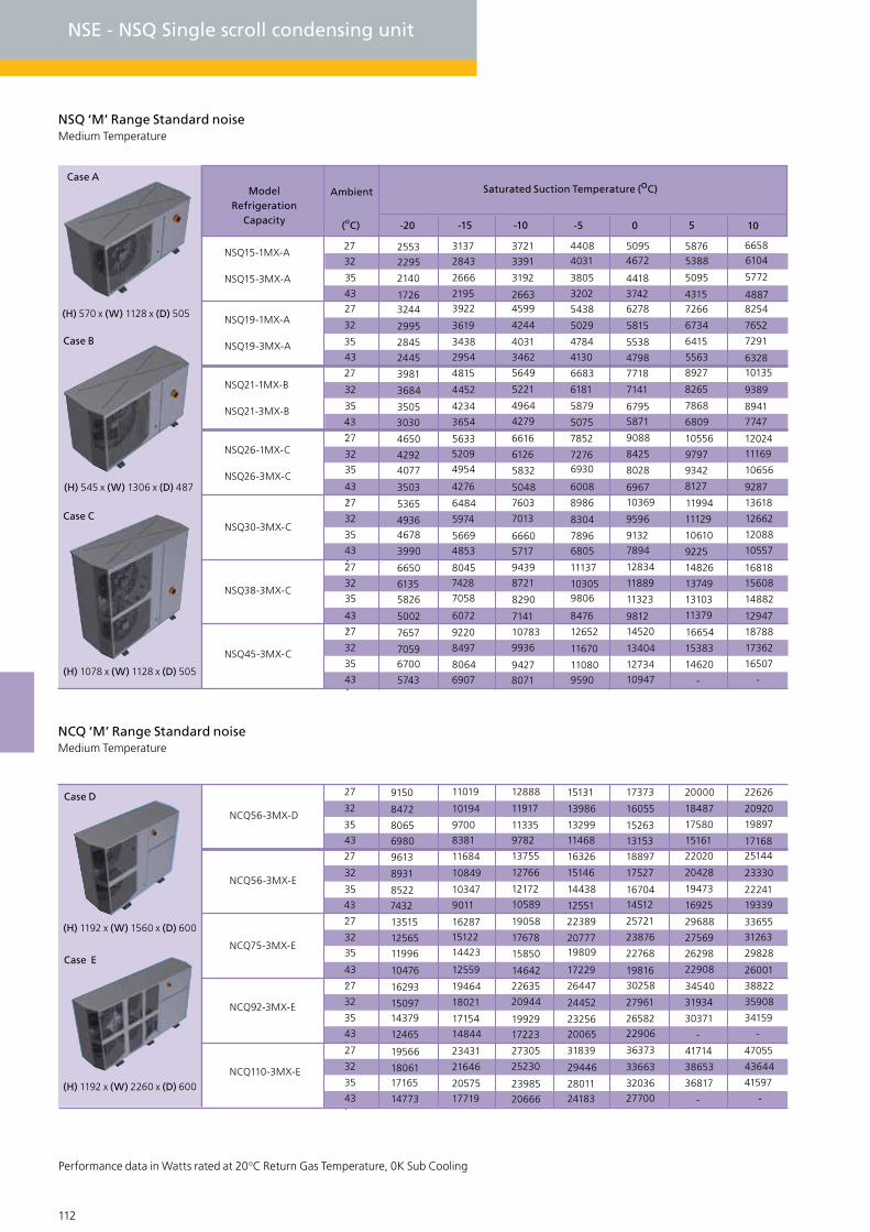
27
32
35
43
NCQ110-3MX-E
19566
1806117165
14773 17719
23431
21646
20575
27305
25230
23985
20666
31839
29446
2801124183
36373
33663
32036
27700
41714
38653
36817
-
47055
43644
41597
-
112 113
NSE - NSQ Single scroll condensing unit
NSQ ‘M’ Range Standard noiseMedium Temperature
27
32
35
1050-5-10-15-20
4327
32
35
43
27
32
35
43
27
32
35
43
(oC)
Saturated Suction Temperature (oC)ModelRefrigeration
Capacity
Ambient
4954
27
32
35
43 4853
NSQ15-1MX-A
NSQ19-1MX-A
NSQ21-1MX-B
NSQ26-1MX-C
NSQ30-3MX-C
2553
2295
2140
17263244
2995
2845
2445
3981
3684
3505
3030
4650
4292
4077
3503
5365
49364678
3990
3137
2843
2666
21953922
3619
3438
2954
4815
4452
4234
3654
5633
5209
4276
6484
5974
5669
3721
3391
3192
26634599
4244
4031
3462
5649
5221
4964
4279
6616
6126
5832
5048
7603
7013
6660
5717
44084031
3805
3202
5438
5029
4784
4130
6683
6181
5879
5075
7852
72766930
6008
8986
8304
78966805
50954672
4418
37426278
5815
5538
4798
7718
7141
67955871
9088
8425
8028
10369
9596
9132
7894
6967
58765388
5095
43157266
6734
6415
5563
8927
8265
7868
6809
10556
9797
9342
8127
11994
11129
10610
9225
66586104
5772
48878254
7652
7291
632810135
9389
8941
7747
12024
11169
10656
9287
13618
12662
12088
10557
27
32
35
43
7058
27
32
35
43 6907
NSQ38-3MX-C
NSQ45-3MX-C
6650
6135
5826
5002
7657
70596700
5743
8045
7428
6072
9220
8497
8064
9439
8721
8290
7141
10783
9936
9427
8071
11137
103059806
8476
12652
11670
110809590
12834
11889
11323
14520
13404
12734
10947
9812
14826
13749
13103
11379
16654
15383
14620
-
16818
15608
14882
12947
18788
17362
16507
-
NSQ15-3MX-A
NSQ19-3MX-A
NSQ21-3MX-B
NSQ26-3MX-C
NCQ ‘M’ Range Standard noiseMedium Temperature
27
32
35
43
27
32
35
43
27
32
35
43
27
32
35
43
NCQ56-3MX-D
NCQ56-3MX-E
NCQ75-3MX-E
NCQ92-3MX-E
9150
8472
8065
6980
9613
8931
8522
7432
13515
12565
11996
10476
16293
1509714379
12465
14423
14844
11019
10194
9700
8381
11684
10849
10347
9011
16287
15122
12559
19464
18021
17154
12888
11917
11335
9782
13755
12766
12172
10589
19058
17678
15850
14642
22635
20944
19929
17223
15131
13986
13299
11468
16326
15146
14438
12551
22389
2077719809
17229
26447
24452
2325620065
17373
16055
15263
13153
18897
17527
1670414512
25721
23876
22768
30258
27961
26582
22906
19816
20000
18487
17580
15161
22020
20428
19473
16925
29688
27569
26298
22908
34540
31934
30371
-
22626
20920
19897
1716825144
23330
22241
19339
33655
31263
29828
26001
38822
35908
34159
-
Performance data in Watts rated at 20oC Return Gas Temperature, 0K Sub Cooling
Case D
(H) 1192 x (W) 1560 x (D) 600
(H) 1192 x (W) 2260 x (D) 600
Case E
Case C
(H) 1078 x (W) 1128 x (D) 505
Case A
(H) 570 x (W) 1128 x (D) 505
Case B
(H) 545 x (W) 1306 x (D) 487
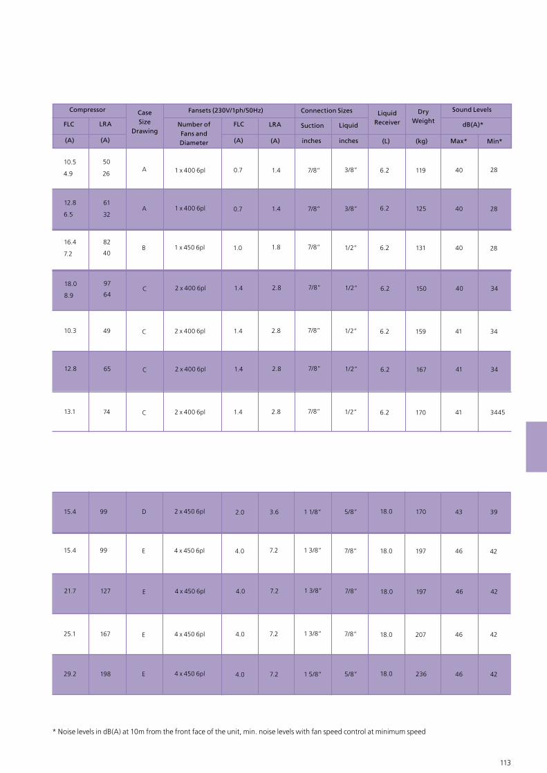
5/8” 18.0198 E 4 x 450 6pl 4.0 7.2 1 5/8” 236 46 4229.2
112 113
FLC LRA
(A) (A)
Compressor
FLC LRA
(A) (A) inches inches (L) (kg)
DryWeight
Max* Min*
dB(A)*
Sound Levels
3/8”
3/8”
1/2”
1/2”
6.2
6.2
6.2
6.2
50
61
82
49
A
A
B
C
1 x 400 6pl
1 x 400 6pl
1 x 450 6pl
2 x 400 6pl
0.7
0.7
1.0
1.4
1.4
1.4
1.8
2.8
7/8”
7/8”
7/8”
7/8”
119
125
131
159
40
40
40
41
28
28
28
34
LiquidSuction
CaseSize
DrawingNumber of Fans and Diameter
Connection Sizes LiquidReceiver
Fansets (230V/1ph/50Hz)
12.8
16.4
10.3
10.5
1/2” 6.297
C 2 x 400 6pl 1.4 2.8 7/8” 150 40 3418.0
1/2” 6.274 C 2 x 400 6pl 1.4 2.8 7/8” 170 41 344513.1
1/2” 6.265 C 2 x 400 6pl 1.4 2.8 7/8” 167 41 3412.8
5/8”
7/8”
7/8”
18.0
18.0
18.0
99
99
167
D
E
E
2 x 450 6pl
4 x 450 6pl
4 x 450 6pl
2.0
4.0
4.0
3.6
7.2
7.2
1 1/8”
1 3/8”
1 3/8”
170
197
207
43
46
46
39
42
42
15.4
15.4
25.1
7/8” 18.0127 E 4 x 450 6pl 4.0 7.2 1 3/8” 197 46 4221.7
* Noise levels in dB(A) at 10m from the front face of the unit, min. noise levels with fan speed control at minimum speed
6.5
7.2
4.9
8.9
26
32
40
64
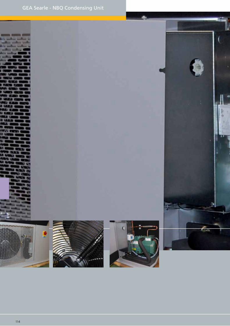
114 115
GEA Searle - NBQ Condensing Unit
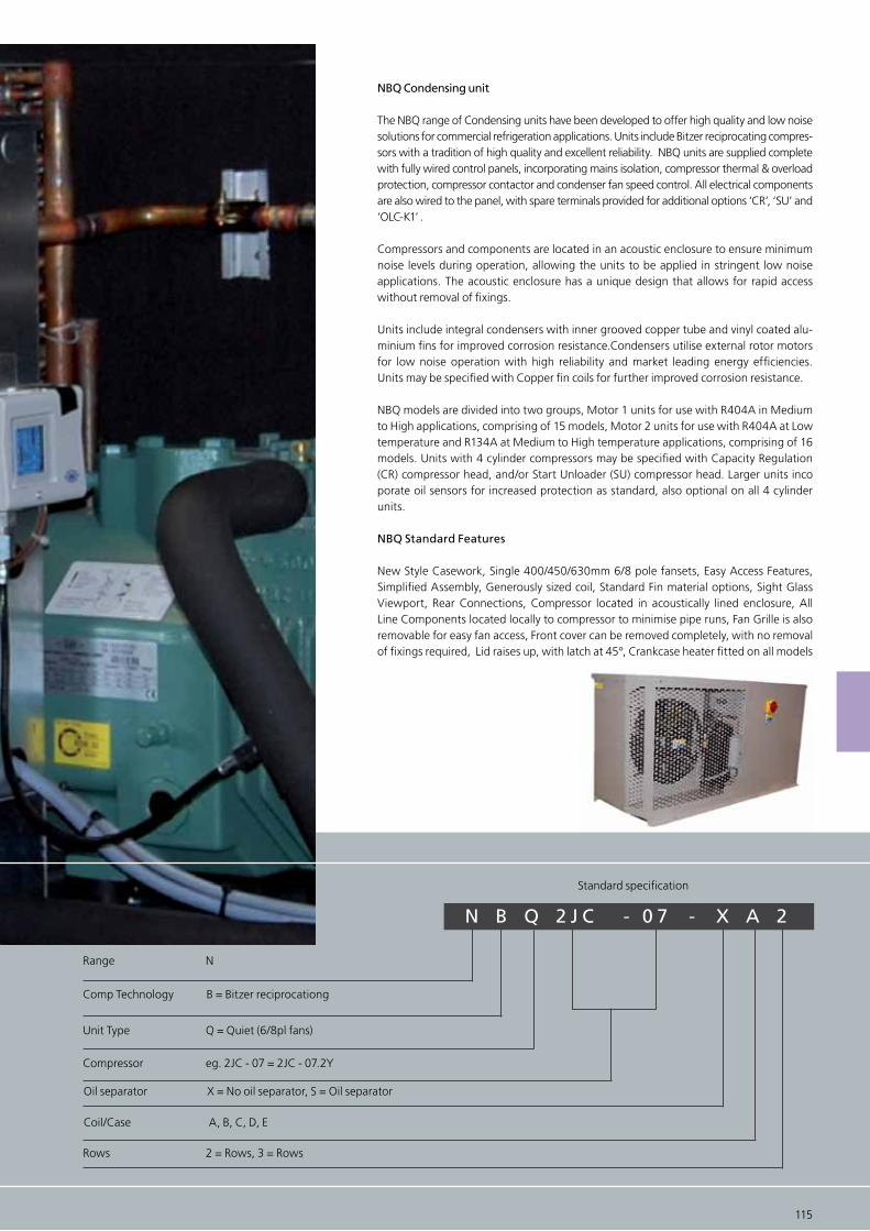
NBQ Condensing unit
The NBQ range of Condensing units have been developed to offer high quality and low noise solutions for commercial refrigeration applications. Units include Bitzer reciprocating compres-sors with a tradition of high quality and excellent reliability. NBQ units are supplied complete with fully wired control panels, incorporating mains isolation, compressor thermal & overload protection, compressor contactor and condenser fan speed control. All electrical components are also wired to the panel, with spare terminals provided for additional options ‘CR’, ‘SU’ and ‘OLC-K1’ .
Compressors and components are located in an acoustic enclosure to ensure minimum noise levels during operation, allowing the units to be applied in stringent low noise applications. The acoustic enclosure has a unique design that allows for rapid access without removal of fixings.
Units include integral condensers with inner grooved copper tube and vinyl coated alu-minium fins for improved corrosion resistance.Condensers utilise external rotor motors for low noise operation with high reliability and market leading energy efficiencies. Units may be specified with Copper fin coils for further improved corrosion resistance.
NBQ models are divided into two groups, Motor 1 units for use with R404A in Medium to High applications, comprising of 15 models, Motor 2 units for use with R404A at Low temperature and R134A at Medium to High temperature applications, comprising of 16 models. Units with 4 cylinder compressors may be specified with Capacity Regulation (CR) compressor head, and/or Start Unloader (SU) compressor head. Larger units inco porate oil sensors for increased protection as standard, also optional on all 4 cylinder units.
NBQ Standard Features
New Style Casework, Single 400/450/630mm 6/8 pole fansets, Easy Access Features, Simplified Assembly, Generously sized coil, Standard Fin material options, Sight Glass Viewport, Rear Connections, Compressor located in acoustically lined enclosure, All Line Components located locally to compressor to minimise pipe runs, Fan Grille is also removable for easy fan access, Front cover can be removed completely, with no removal of fixings required, Lid raises up, with latch at 45°, Crankcase heater fitted on all models
N B Q 2 J C - 0 7 - X A 2
Range N
Comp Technology B = Bitzer reciprocationg
Rows 2 = Rows, 3 = Rows
Unit Type Q = Quiet (6/8pl fans)
Compressor eg. 2JC - 07 = 2JC - 07.2Y
Oil separator X = No oil separator, S = Oil separator
Coil/Case A, B, C, D, E
114 115
Standard specification
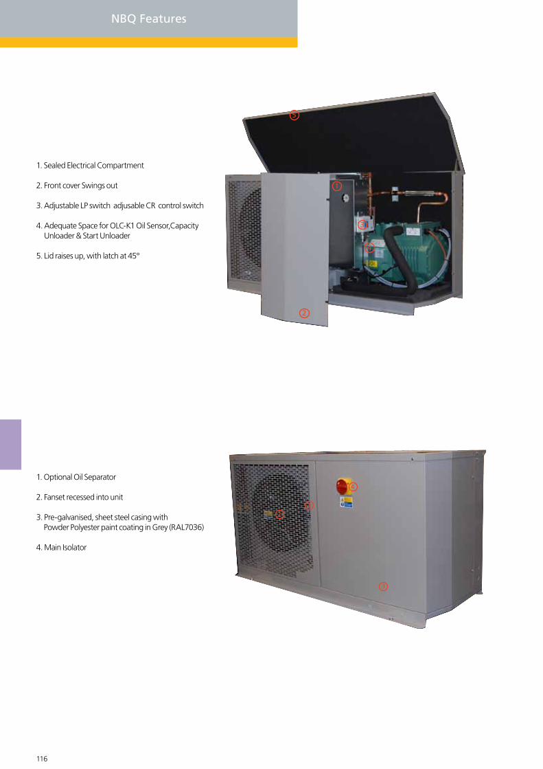
116 117
NBQ Features
1. Sealed Electrical Compartment
2. Front cover Swings out
3. Adjustable LP switch adjusable CR control switch
4. Adequate Space for OLC-K1 Oil Sensor,Capacity Unloader & Start Unloader
5. Lid raises up, with latch at 45°
1
2
5
4
3
1. Optional Oil Separator
2. Fanset recessed into unit
3. Pre-galvanised, sheet steel casing with Powder Polyester paint coating in Grey (RAL7036)
4. Main Isolator
12
3
4
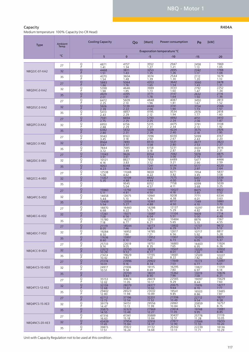
116 117
Unit with Capacity Regulation not to be used at this condition.
Capacity R404AMedium temperature 100% Capacity (no CR Head)
-15-10-505
Cooling Capacity
°C
NBQ4EC-6-XD2
NBQ4DC-7-XD2
NBQ4FC-5-XD2
NBQ2DC-3-XB3
NBQ2EC-3-XB2
NBQ2CC-4-XB3
NBQ2GC-2-XA2
NBQ2FC-3-XA2
NBQ2HC-2-XA2
NBQ2JC-07-XA2
NBQ4CC-9-XD3
NBQ4VCS-10-XD3
NBQ4TCS-12-XE2
NBQ4NCS-20-XE3
NBQ4PCS-15-XE3
35
32
35
27
32
35
27
32
27
32
35
27
32
35
27
32
35
27
27
32
35
27
32
35
27
32
35
27
32
35
27
32
35
27
32
35
27
32
35
27
32
35
27
32
35
QPQPQPQPQPQPQPQPQPQPQPQPQPQPQPQPQPQPQPQPQPQPQPQPQPQPQPQPQPQPQPQPQPQPQPQPQPQPQPQPQPQPQPQPQP
Type Ambient Temp.
Qo [Watt]
Power consumption
Pe [kW]
-20
Evaporation temperature °C
48711.4144681.5140701.5458831.8653981.9849292.0164722.2559262.3954132.4375912.7569502.8863822.8093433.4585643.6778443.72110433.91101214.1692634.23125385.06114575.35
159605.11146585.44134095.54188706.68172617.08157807.18211198.05192848.50176368.60257339.742357210.292161410.422727410.012491710.51
3515312.023215912.682940212.804271213.733917914.473587514.554731616.634343917.453981517.51
41571.3438111.4336041.4850641.7646461.8543951.9156092.1051392.2248572.2966942.2561562.2958322.3181633.1874903.3770853.4996263.6188273.8383483.96110484.62101094.8895455.04137924.81126755.10120045.27164606.22150716.56142376.77185447.46169527.86159978.10226199.05207509.53196299.83239969.16219369.58207009.843067411.052807911.612652311.943719612.543415113.133232313.484134115.183795415.843592216.24
35521.2732531.3530741.3943531.6539891.7337711.7848481.9644402.0641952.1257932.2553152.3150282.3670962.9265103.0861583.1883543.3476583.5272413.6396594.2288424.4483524.57119104.50109414.74103614.88142985.75130876.04123616.21161736.87147857.21139527.41197518.35181298.77171559.02209228.34191158.69180318.902661910.172437710.622303210.893220111.522955611.992796912.273588913.843291614.373113214.68
19691.0517881.0816791.1024781.3122521.3421161.3628131.5225661.5724181.6034101.8731081.9229261.9541672.2038232.2736162.3148752.5144662.5942202.6458373.0853393.1950393.2569223.5263343.6359803.7084584.3677144.4872674.5596725.1388175.2883055.37119246.26109326.48103376.62124976.01113596.14106766.21156297.60142777.77
182178.58167578.75158818.852111910.051925510.201813610.29
134657.87
24581.1322421.1721121.2030601.4327921.4726321.5034501.6731541.7329761.7741512.0637912.1335752.1850992.4346772.5344242.5959782.7954772.9051772.9770543.4564573.5960993.6884753.8577714.0173494.10102974.8294095.0088765.10117375.71107175.92101066.05144036.95132207.24125097.42151736.77138276.97130197.08190978.44174768.70
227129.54208599.79197489.952577811.282356611.552223911.71
165038.86
29471.2126951.2625441.3036421.5433331.6031471.6440871.8137411.9035341.9448922.2444752.3442242.4060302.6755312.8052312.8770823.0664893.2161343.2982713.8275754.0071584.11100274.1892084.3887174.50121375.29111045.51104845.65138026.29126176.56119076.73168837.65155078.01146818.22178497.53162957.80153627.96225659.29206759.64
2720610.492496110.842361411.053043712.512787712.902634213.13
195419.85
NBQ - Motor 1

118 119
NBQ - Motor 2
NBQ4FC-3-XD2
NBQ4EC-4-XD2
NBQ2CC-3-XA3
NBQ2EC-2-XA3
NBQ2FC-2-XA2
NBQ2DC-2-XA3
NBQ2HC-1-XA2
NBQ2GC-2-XA2
NBQ2JC-07-XA2
NBQ2KC-05-XA2
NBQ4DC-5-XD2
NBQ4CC-6-XD3
NBQ4VCS-6-XD3
NBQ4PCS-10-XD3
NBQ4TCS-8-XD3
35
32
35
27
32
35
27
32
27
32
35
27
32
35
27
32
35
27
27
32
35
27
32
35
27
32
35
27
32
35
27
32
35
27
32
35
27
32
35
27
32
35
27
32
35
Capacity R404ALow temperature
Unit with Capacity Regulation not to be used at this condition.
NBQ4NCS-12-XD3
27
32
35
QPQPQP
QPQPQPQPQPQPQPQPQPQPQPQPQPQPQPQPQPQPQPQPQPQPQPQPQPQPQPQPQPQPQPQPQPQPQPQPQPQPQPQPQPQPQPQPQP
22630.9020600.9419370.9729471.2126951.2625441.3035811.5432711.6030851.6440871.8137411.9035341.9448552.2844292.3841742.4458752.6953832.8150882.8865843.1560073.2956613.3776723.9569974.1265934.2399614.3191494.4986624.60119575.22109215.44102995.57139386.38127226.65119936.81168397.65154488.00146128.22177377.83161918.10152648.26204499.701863910.021755410.222268711.372066811.751945711.982466113.642242814.05
1811210.411646810.621548110.75
14740.8113310.8312460.8519691.0517881.0816791.1024361.2922121.3220781.3428131.5225661.5724181.6034021.8930951.9429111.9841172.1937632.2535502.2946612.5342432.6039922.6555303.1250433.2347513.3068773.6162983.7159513.7683534.3176134.4371694.5098545.2389825.3884595.47119046.25108916.47102836.60125276.22114036.36
146607.63133357.80125407.91164038.77149208.97140319.09
107286.44
121397.70109657.73102617.75
8640.707680.707110.6912080.8910820.8910070.8915301.0613701.0512751.0517931.2416221.2515191.2622161.5020011.5218721.5326781.7424311.7622831.7730521.9827551.9925762.0036722.4033342.4431312.4744282.9340232.9537802.9654153.4249033.4545963.4764494.0958454.1454824.1778354.8871234.9866965.0481714.777384.80
96755.8187425.8581825.88108926.5898446.5992156.60
69114.82
151259.06137169.18128719.25
11690.7610500.769780.7715880.9714350.9813430.9919831.1817911.1916761.1923031.3820941.4119691.4328091.6925481.7323911.7533971.9730972.0129172.0338562.2534992.3032842.3346012.7641882.8439412.8856523.2751603.3348653.3668843.8662583.9458833.9881514.6674134.7669704.8298705.5690075.7284895.82103495.5093935.58
121686.72110386.83103616.89136477.68123827.78116237.84
88205.63
2138712.031944812.341828412.53
18690.8616950.8915920.9124581.1322421.1721121.2030081.4227411.4625811.4934501.6731541.7329761.7741282.0837622.1635422.2149962.4445732.5343192.5856232.8451252.9548263.0166013.5460203.6856723.7684193.9677244.1073074.18101554.7692674.9387345.03118965.81108526.01102266.14143726.95131697.24124487.41151327.03137977.23129967.35175548.67159878.91150479.061954510.071779410.361674410.53
6410.635620.615140.609250.798180.787540.7711850.9410500.929690.9114051.0912611.0911751.0917511.3015701.3114621.3221161.5319081.5317831.5324171.7221661.7120161.7029192.0826362.09
34932.5731532.5729492.5742732.9838462.9735892.9751073.5346023.5442993.5562434.2356444.2652854.2964444.0957864.07
76724.8769034.6764414.5585965.6176855.54
53924.06
96186.5285966.45
-35-30-25-20-15-10
Cooling Capacity
°C
Type Ambient Temp.
Qo [Watt]
Power consumption
Pe [kW]
Evaporation temperature °C
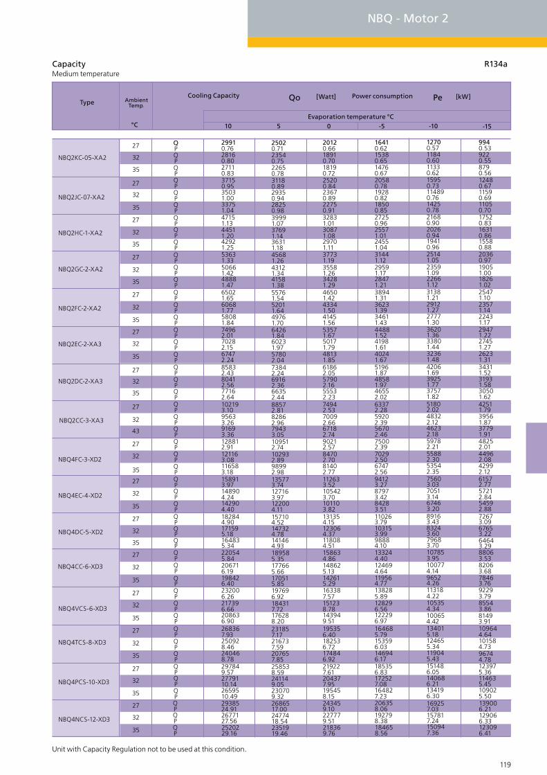
118 119
NBQ4FC-3-XD2
NBQ4EC-4-XD2
NBQ2CC-3-XA3
NBQ2EC-2-XA3
NBQ2FC-2-XA2
NBQ2DC-2-XA3
NBQ2HC-1-XA2
NBQ2GC-2-XA2
NBQ2JC-07-XA2
NBQ2KC-05-XA2
NBQ4DC-5-XD2
NBQ4CC-6-XD3
NBQ4VCS-6-XD3
NBQ4PCS-10-XD3
NBQ4TCS-8-XD3
35
32
35
27
32
43
27
32
27
32
35
27
32
35
27
32
35
27
27
32
35
27
32
35
27
32
35
27
32
35
27
32
35
27
32
35
27
32
35
27
32
35
27
32
35
Capacity R134aMedium temperature
-15-10-50510
Cooling Capacity
°C
Type Ambient Temp.
Qo [Watt]
Power consumption
Pe [kW]
Evaporation temperature °C
Unit with Capacity Regulation not to be used at this condition.
NBQ4NCS-12-XD3
27
32
35
QPQPQP
QPQPQPQPQPQPQPQPQPQPQPQPQPQPQPQPQPQPQPQPQPQPQPQPQPQPQPQPQPQPQPQPQPQPQPQPQPQPQPQPQPQPQPQPQP
25020.7123540.7522650.7831180.8929350.9428250.9839991.0737691.1436311.1845681.2643121.3441581.3855761.5452011.6449761.7064261.8460231.9757802.0473842.2469162.3666352.4488572.8182862.9679433.05109512.74102932.8998992.98135773.74127163.97122004.11157104.52147324.78141464.93189585.35177665.66170515.85197696.92184317.72176288.20231857.17216737.59207657.85258538.59241149.05230709.322686517.002477418.542351919.46
20120.6618910.7018190.7225200.8423670.8922750.9132831.0130871.0829701.1137731.1935581.2634281.2946501.4243341.5041451.5653571.6750171.7948131.8561862.0557902.1655532.2374942.5370092.6667182.7490212.5784702.7081402.77112633.52105423.70101103.82131354.15123064.37118084.51158634.86148625.13142615.29163387.57151238.78143949.51195356.40182536.72174846.92219227.61204377.95195458.15243459.10227779.51218369.76
2938524.912677127.562520229.16
29910.7628160.8027110.8337150.9535031.0033751.0447151.134451
42921.2553631.3350661.4248881.4765021.6560681.7758081.8474962.0170282.1567472.2485832.4380412.5677162.64102193.1095633.2691693.36128812.91121163.08116583.18158913.97148904.24142904.40182844.90171595.18164835.34220545.84206716.19198426.40232006.26217396.66208636.90268367.93250928.46240468.78297849.572779110.142659510.49
1.20
139006.21129066.33123096.41
9940.539220.558790.5612480.6711590.6911050.7017520.8316310.8615580.8820360.9719051.0018261.0225471.1023571.1422431.1729471.2227451.2726231.3134311.5231931.5830501.6242511.7939561.8737791.9148252.0144962.0842992.1261572.7757212.8454592.8872673.0967653.2264643.2988063.5382063.6878463.7692293.7985543.86
109644.64101584.7396744.78123975.36114635.45109025.50
81493.91
206358.06192798.38184658.56
16410.6215380.6514760.6720580.7819280.8218500.8527250.9625571.0124551.0431441.1229591.1728471.2138941.3136231.3934611.4344881.5241981.6140241.6751961.8748581.9746552.0263372.2859202.3956702.4675002.3970292.5067472.5694123.2787973.4284283.51110263.79103153.9998884.10133244.40124694.64119564.77138285.89128296.56122296.97164685.79153596.03146946.17185356.83172527.08164827.23
12700.5711840.6011330.6215950.73114890.7614250.7821680.9020260.9419410.9625141.0523591.0922661.1231381.2129121.2727771.3036201.3633801.4432361.4842061.6939251.7737571.8251802.0248322.1246232.1859782.2155882.3053542.3575603.0370513.1467463.2089163.4383243.6079683.70107853.95100774.1496524.26113184.22105354.34
134015.18124655.34119045.43151486.05140686.21134196.30
100654.42
169257.03157817.24150947.36
NBQ - Motor 2
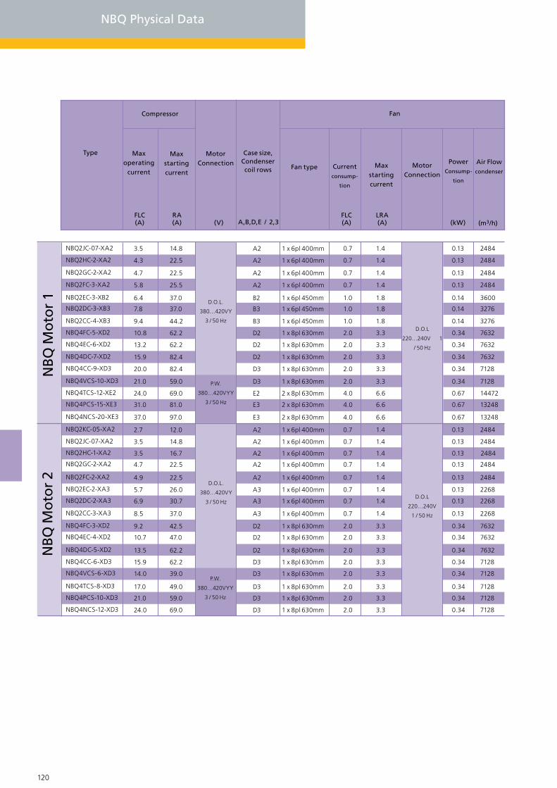
120 121
NBQ Physical Data
Max operating
current
Type
FLC(A)
Max starting current
RA(A)
Compressor
Case size,Condenser coil rows
A,B,D,E / 2,3
Fan type Current
consump-
tion
FLC(A)
Fan
Max starting current
LRA(A)
Power Consump-
tion
Air Flow condenser
(kW)
3.5
4.3
4.7
5.8
6.4
7.8
9.4
10.8
13.2
15.9
20.0
21.0
24.0
31.0
37.0
2.7
3.5
3.5
4.7
4.9
5.7
6.9
8.5
9.2
10.7
13.5
15.9
14.0
17.0
21.0
24.0
NBQ2JC-07-XA2
NBQ2HC-2-XA2
NBQ2GC-2-XA2
NBQ2FC-3-XA2
NBQ2EC-3-XB2
NBQ2DC-3-XB3
NBQ2CC-4-XB3
NBQ4FC-5-XD2
NBQ4EC-6-XD2
NBQ4DC-7-XD2
NBQ4CC-9-XD3
NBQ4VCS-10-XD3
NBQ4TCS-12-XE2
NBQ4PCS-15-XE3
NBQ4NCS-20-XE3
NBQ2KC-05-XA2
NBQ2JC-07-XA2
NBQ2HC-1-XA2
NBQ2GC-2-XA2
NBQ2FC-2-XA2
NBQ2EC-2-XA3
NBQ2DC-2-XA3
NBQ2CC-3-XA3
NBQ4FC-3-XD2
NBQ4EC-4-XD2
NBQ4DC-5-XD2
NBQ4CC-6-XD3
NBQ4VCS-6-XD3
NBQ4TCS-8-XD3
NBQ4PCS-10-XD3
NBQ4NCS-12-XD3
NB
Q M
oto
r 1
NB
Q M
oto
r 2
14.8
22.5
22.5
25.5
37.0
37.0
44.2
62.2
62.2
82.4
82.4
59.0
69.0
81.0
97.0
12.0
14.8
16.7
22.5
22.5
26.0
30.7
37.0
42.5
47.0
62.2
62.2
39.0
49.0
59.0
69.0
A2
A2
A2
A2
B2
B3
B3
D2
D2
D2
D3
D3
E2
E3
E3
A2
A2
A2
A2
A2
A3
A3
A3
D2
D2
D2
D3
D3
D3
D3
D3
1 x 6pl 400mm
1 x 6pl 400mm
1 x 6pl 400mm
1 x 6pl 400mm
1 x 6pl 450mm
1 x 6pl 450mm
1 x 6pl 450mm
1 x 8pl 630mm
1 x 8pl 630mm
1 x 8pl 630mm
1 x 8pl 630mm
1 x 8pl 630mm
2 x 8pl 630mm
2 x 8pl 630mm
2 x 8pl 630mm
1 x 6pl 400mm
1 x 6pl 400mm
1 x 6pl 400mm
1 x 6pl 400mm
1 x 6pl 400mm
1 x 6pl 400mm
1 x 6pl 400mm
1 x 6pl 400mm
1 x 8pl 630mm
1 x 8pl 630mm
1 x 8pl 630mm
1 x 8pl 630mm
1 x 8pl 630mm
1 x 8pl 630mm
1 x 8pl 630mm
1 x 8pl 630mm
0.7
0.7
0.7
0.7
1.0
1.0
1.0
2.0
2.0
2.0
2.0
2.0
4.0
4.0
4.0
0.7
0.7
0.7
0.7
0.7
0.7
0.7
0.7
2.0
2.0
2.0
2.0
2.0
2.0
2.0
2.0
1.4
1.4
1.4
1.4
1.8
1.8
1.8
3.3
3.3
3.3
3.3
3.3
6.6
6.6
6.6
1.4
1.4
1.4
1.4
1.4
1.4
1.4
1.4
3.3
3.3
3.3
3.3
3.3
3.3
3.3
3.3
0.13
0.13
0.13
0.13
0.14
0.14
0.14
0.34
0.34
0.34
0.34
0.34
0.67
0.67
0.67
0.13
0.13
0.13
0.13
0.13
0.13
0.13
0.13
0.34
0.34
0.34
0.34
0.34
0.34
0.34
0.34
2484
2484
2484
2484
3600
3276
3276
7632
7632
7632
7128
7128
14472
13248
13248
2484
2484
2484
2484
2484
2268
2268
2268
7632
7632
7632
7128
7128
7128
7128
7128
(m3/h)
Motor Connection
(V)
D.O.L.
380…420VY
3 / 50 Hz
P.W.
380…420VYY
3 / 50 Hz
D.O.L.
380…420VY
3 / 50 Hz
P.W.
380…420VYY
3 / 50 Hz
D.O.L
220…240V 1
/ 50 Hz
D.O.L
220…240V
1 / 50 Hz
Motor Connection

120 121
Suction valve
Inch
Connections
Refrigerant Outlet
Inch
Total volume
(L)
Receiver
Maximum refrigerant charge
R134a(kg)
R404A / R507A(kg)
Weight (Stand) Sound Levels
(kg) Max* Min*
dB(A)*
6.2
6.2
6.2
6.2
6.2
6.2
6.2
18.0
18.0
18.0
18.0
18.0
18.0
18.0
18.0
6.2
6.2
6.2
6.2
6.2
6.2
6.2
6.2
18.0
18.0
18.0
18.0
18.0
18.0
18.0
18.0
5.7
5.7
5.7
5.7
5.7
5.7
5.7
16.6
16.6
16.6
16.6
16.6
16.6
16.6
16.6
5.7
5.7
5.7
5.7
5.7
5.7
5.7
5.7
16.6
16.6
16.6
16.6
16.6
16.6
16.6
16.6
5.0
5.0
5.0
5.0
5.0
5.0
5.0
14.4
14.4
14.4
14.4
14.4
14.4
14.4
14.4
5.0
5.0
5.0
5.0
5.0
5.0
5.0
5.0
14.4
14.4
14.4
14.4
14.4
14.4
14.4
14.4
136
138
138
140
172
172
172
224
224
225
282
330
342
343
351
136
136
137
138
138
164
164
166
220
222
224
282
323
325
330
332
38
38
39
39
40
40
40
44
44
44
45
45
48
48
48
38
38
38
39
39
39
39
39
44
44
44
45
45
45
45
45
32
32
33
33
36
36
36
40
41
41
42
42
44
45
45
32
32
32
33
33
33
33
33
40
41
41
42
42
42
42
42
Max noise levels are with Condenser fan/s at maximum speed and compressor fully loaded,
Unit Weights are net dry weights without packing or refrigerant, also not including additional options (Oil separator / SU Head / CR Head)
Type
NBQ2JC-07-XA2
NBQ2HC-2-XA2
NBQ2GC-2-XA2
NBQ2FC-3-XA2
NBQ2EC-3-XB2
NBQ2DC-3-XB3
NBQ2CC-4-XB3
NBQ4FC-5-XD2
NBQ4EC-6-XD2
NBQ4DC-7-XD2
NBQ4CC-9-XD3
NBQ4VCS-10-XD3
NBQ4TCS-12-XE2
NBQ4PCS-15-XE3
NBQ4NCS-20-XE3
NBQ2KC-05-XA2
NBQ2JC-07-XA2
NBQ2HC-1-XA2
NBQ2GC-2-XA2
NBQ2FC-2-XA2
NBQ2EC-2-XA3
NBQ2DC-2-XA3
NBQ2CC-3-XA3
NBQ4FC-3-XD2
NBQ4EC-4-XD2
NBQ4DC-5-XD2
NBQ4CC-6-XD3
NBQ4VCS-6-XD3
NBQ4TCS-8-XD3
NBQ4PCS-10-XD3
NBQ4NCS-12-XD3
5/8”
5/8”
5/8”
5/8”
7/8”
7/8”
7/8”
7/8”
1 1/8”
1 1/8”
1 1/8”
1 1/8”
1 3/8”
1 5/8”
1 5/8”
5/8”
5/8”
5/8”
5/8”
5/8”
7/8”
7/8”
7/8”
7/8”
1 1/8”
1 1/8”
1 1/8”
1 1/8”
1 3/8”
1 3/8”
1 3/8”
3/8”
3/8”
3/8”
3/8”
1/2”
1/2”
1/2”
5/8”
5/8”
7/8”
7/8”
7/8”
7/8”
7/8”
7/8”
3/8”
3/8”
3/8”
3/8”
3/8”
3/8”
3/8”
3/8”
5/8”
5/8”
5/8”
5/8”
7/8”
7/8”
7/8”
7/8”
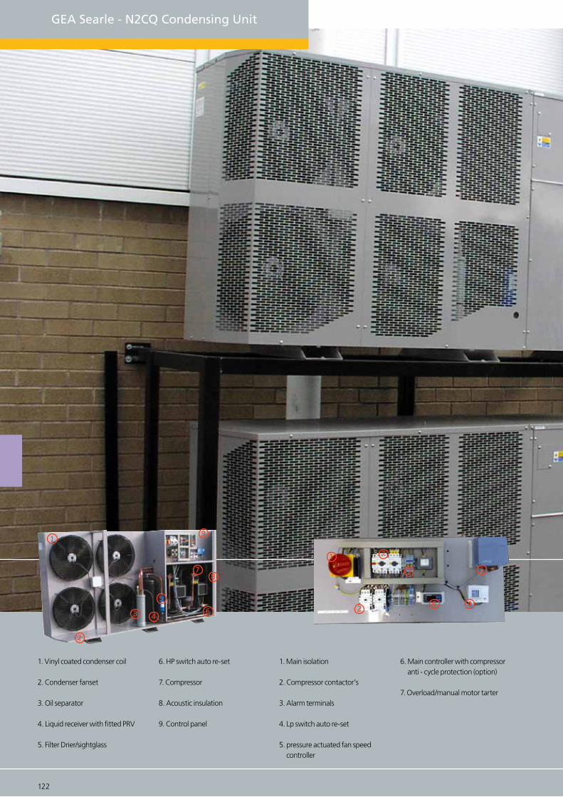
GEA Searle - N2CQ Condensing Unit
6. HP switch auto re-set
7. Compressor
8. Acoustic insulation
9. Control panel
7
122 123
1. Vinyl coated condenser coil
2. Condenser fanset
3. Oil separator
4. Liquid receiver with fitted PRV
5. Filter Drier/sightglass
1
2
3 4
5
6
78
9
6. Main controller with compressor anti - cycle protection (option)
7. Overload/manual motor tarter
1. Main isolation
2. Compressor contactor’s
3. Alarm terminals
4. Lp switch auto re-set
5. pressure actuated fan speed controller
1
2
3
4
5
6
7

N2CQ Condensing unit
GEA Searle N2CQ twin scroll compressor condensing units compliment the NSQ range by ex-tending the range through the use of two scroll compressors. The twin compressor configura-tion provides capacity control in steps of 100% and 50% to suit projects with a variable refrig-eration load. This makes the N2CQ the flexible option for larger convenience stores, garage forecourts and small supermarkets.
The N2CQ range comprises seven low temperature and eight medium temperature models us-ing refrigerants R404A/R507 and R407C. The low temperature models (-40 °C to -10°C) cover a capacity range of 4.03 kW to 19.6 kW while the medium temperature units (-20°C to +10°C) range from 7.27 kW to 23.28 kW.
N2CQ Standard Features
CE Marked Unit, Weatherproof housing with separate, acoustically lined compressor compartment, Concealed, low noise condenser fans, Copper tube coil with vinyl-coatedaluminium fins, Capacity control 100-50-0%, Fully-wired control panel with Mains Iso-lator, Low ambient fan speed control (FSC), Liquid receiver with fitted pressure relief valve, Compressor motor starter with short circuit and overload protection.
Twin scroll compressors including contactors (with liquid injection and oil management system on low temperature ‘LS’ models), Volt-free contact for alarm signal (relay), HP/LP switch auto reset, Sight glass and filter drier, Rotalock service valves on compressorsand receiver, Oil separator, Electronic Step Controller
Options
Copper fin coil, Fully crated packing
N 2C Q 112 - 3 M X - C 3 F I - V
Range NComp Technology 2C = Twin Scroll compressor
Unit Type Q = Quiet (6pl)Compressor eg. 112 =2xZB56, 22 = 2xZF11
Opitional Extras V = Vinyl coated aluminium, C = Copper fin, O = Evaporator contactor, S = Solenoid valve, G = Evap. Contactor + Sol. valve
Phase 3 = 3 PhaseTemperature M = Medium, L = Low
Oil separator S = Oil separator, X = N0 oil separator, V = EVI CompressorCoil/Case D, E
Rows 2,3Control package F = Fan speed controller, W = Fan speed controller + Anti cycle timer + Alarm relay T = Anti cycle timer + Alarm relay, E = Electronic Controller + EC Fans
Acoustic insulation I = Insulation
Standard specification Options
122 123

124 125
N2CQ Twin scroll condensing unit
N2CQ ‘L’ Range Low noise twin compressorLow Temperature
27
32
35
-10-15-20-25-30-35-40
4327
32
35
43
27
32
35
43
27
32
35
43
(oC)
Saturated Suction Temperature (oC)Model Ambient
6566
27
32
35
43 6785
N2CQ18-3LS-D
N2CQ22-3LS-D
N2CQ26-3LS-D
N2CQ30-3LS-D
N2CQ36-3LS-D
3362
3157
3034
27064207
3932
3768
3329
4707
4444
4286
3865
5796
5419
5193
4590
6957
64836198
5439
4293
4026
3865
34375331
4981
4771
4211
6028
5636
5401
4775
7346
6859
5786
8724
8118
7755
5225
4895
4697
41686456
6030
5775
5093
7349
6829
6517
5685
8896
8299
7940
6983
10492
9754
9312
8132
64135994
5742
5072
7829
7305
6991
6152
8965
8314
7924
6883
10855
100829618
8380
12697
11782
112339769
76017093
6788
59759202
8580
8207
7212
10581
9800
93318081
12814
11865
11295
14903
13810
13155
11407
9777
91438528
8159
717610982
10227
9773
8564
12559
11649
11103
9647
15165
14031
13352
11539
17537
16232
15449
13360
106859964
9531
837612762
11873
11340
991714536
13498
12875
11214
17515
16198
15408
13300
20172
18654
17743
-
27
32
35
43
9910
27
32
35
43 10965
N2CQ48-3LS-E
N2CQ66-3LS-E
8708
8083
7707
6706
10364
96949292
8219
11123
10365
8696
14201
13189
12583
13538
12647
12112
10686
18037
16685
15873
13710
16515
1540814744
12974
21895
20224
1922116546
19492
18170
17377
25754
23763
22568
19381
15261
23196
21584
20618
18040
30079
27792
26420
22761
26899
24999
23859
20818
34404
31822
30272
-
N2CQ ‘L’ EVI Low noise twin compressorLow Temperature
27
32
35
43
27
32
35
43
27
32
35
43
27
32
35
43
N2CQ26-3LV-D
N2CQ36-3LV-E
N2CQ48-3LV-E
N2CQ66-3LV-E
6634
6333
6153
5671
9920
9846
9801
9682
11684
11381
11199
10715
16226
15982
15836
-
14304
-
8364
8054
7868
7372
12161
11982
11874
11587
14806
14492
13802
20075
19660
19410
10093
9774
9583
9073
14401
14117
13947
13493
17928
17604
17409
16889
23924
23337
22985
-
12264
11933
11735
11205
17264
16860
16618
15971
21613
21166
20898
20182
28577
27754
27261
-
14435
14092
13887
13338
20127
19603
19288
18450
25298
24728
24387
33230
32171
31536
-
23476
17268
16940
16743
16743
16217
23779
23159
22787
29653
28878
28413
27173
38836
37514
36720
-
20100
19787
19599
-
27432
26715
26285
25138
34008
33027
32439
-
44442
42856
41904
-
Performance data in Watts rated at 20oC Return Gas Temperature, 0K Sub Cooling
Case A
(H) 570 x (W) 1128 x (D) 505
Case B
(H) 545 x (W) 1306 x (D) 487
Case D & E
(H) 1192 x (W) 1560 x (D) 600
(H) 1192 x (W) 2260 x (D) 600

124 125
FLC LRA
(A) (A)
Compressor
FLC LRA
(A) (A) inches inches (L) (kg)
DryWeight
Max* Min*
dB(A)*
Sound Levels
5/8”
5/8”
5/8”
5/8”
18.0
18.0
18.0
18.0
2 x 40
2 x 46
2 x 52
2 x 74
D
D
D
D
2 x 400 6pl
2 x 400 6pl
2 x 400 6pl
2 x 450 6pl
2.0
2.0
2.0
2.0
3.6
3.6
3.6
3.6
1 1/8”
1 1/8”
1 3/8”
1 3/8”
218
220
241
255
42
42
42
42
38
38
38
38
LiquidSuction
CaseSize
DrawingNumber of Fans and Diameter
Connection Sizes LiquidReceiver
Fansets (230V/1ph/50Hz)
2 x 7.0
2 x 8.0
2 x 12.0
2 x 6.0
5/8” 18.02 x 64 D 2 x 450 6pl 2.0 3.6 1 3/8” 251 42 382 x 10.0
7/8” 18.02 x 134 E 4 x 450 6pl 4.0 7.2 1 5/8” 435 45 412 x 22.3
7/8” 18.02 x 99 E 4 x 450 6pl 4.0 7.2 1 5/8” 435 45 412 x 16.1
5/8”
7/8”
7/8”
18.0
18.0
18.0
2 x 51.5
2 x 74.5
2 x 127
D
E
E
2 x 450 6pl
4 x 450 6pl
4 x 450 6pl
2.0
4.0
4.0
3.6
7.2
7.2
1 3/8”
1 3/8”
1 5/8”
241
305
435
42
45
45
38
41
44
2 x 8.0
2 x 12.0
2 x 22.3
7/8” 18.02 x 99 E 4 x 450 6pl 4.0 7.2 1 5/8” 435 45 442 x 16.1
* Noise levels in dB(A) at 10m from the front face of the unit, min. noise levels with fan speed control at minimum speed
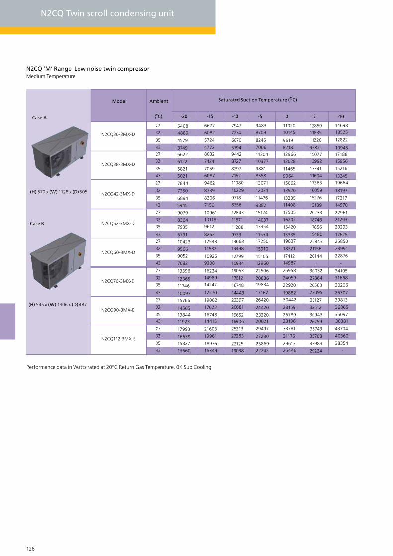
126 127
N2CQ Twin scroll condensing unit
N2CQ ‘M’ Range Low noise twin compressorMedium Temperature
27
32
35
-10 50-5-10-15-20
4327
32
35
43
27
32
35
43
27
32
35
43
(oC)
Saturated Suction Temperature (oC)Model Ambient
9612
27
32
35
43 9308
N2CQ30-3MX-D
N2CQ38-3MX-D
N2CQ42-3MX-D
N2CQ52-3MX-D
N2CQ60-3MX-D
5408
4889
4579
37496622
6122
5821
5021
7844
7250
6894
5945
9079
8364
7935
6791
10423
95669052
7682
6677
6082
5724
47728032
7424
7059
6087
9462
8739
8306
7150
10961
10118
8262
12543
11532
10925
7947
7274
6870
57949442
8727
8297
7152
11080
10229
9718
8356
12843
11871
11288
9733
14663
13498
12799
10934
94838709
8245
7006
11204
10377
9881
8558
13071
12074
11476
9882
15174
1403713354
11534
17250
15910
1510512960
1102010145
9619
821812966
12028
11465
9964
15062
13920
1323511408
17505
16202
15420
19837
18321
17412
14987
13335
1285911835
11220
958215077
13992
13341
11604
17363
16059
15276
13189
20233
18748
17856
15480
22843
21156
20144
-
1469813525
12822
1094517188
15956
15216
1324519664
18197
17317
14970
22961
21293
20293
17625
25850
23991
22876
-
27
32
35
43
14247
27
32
35
43 14415
N2CQ76-3MX-E
N2CQ90-3MX-E
13396
12365
11746
10097
15766
1456513844
11923
16224
14989
12270
19082
17623
16748
19053
17612
16748
14443
22397
20681
19652
16906
22506
2083619834
17162
26420
24420
2322020021
25958
24059
22920
30442
28159
26789
23136
19882
30032
27864
26563
23095
35127
32512
30943
26759
34105
31668
30206
26307
39813
36865
35097
30381
Case A
(H) 570 x (W) 1128 x (D) 505
Case B
(H) 545 x (W) 1306 x (D) 487
27
32
35
43 16349
N2CQ112-3MX-E
17993
1663915827
13660
21603
19961
18976
25213
23283
22125
19038
29497
27230
2586922242
33781
31176
29613
25446
38743
35768
33983
29224
43704
40360
38354
-
Performance data in Watts rated at 20oC Return Gas Temperature, 0K Sub Cooling

126 127
FLC LRA
(A) (A)
Compressor
FLC LRA
(A) (A) inches inches (L) (kg)
DryWeight
Max* Min*
dB(A)*
Sound Levels
5/8”
5/8”
5/8”
5/8”
18.0
18.0
18.0
18.0
2 x 26
2 x 32
2 x 40
2 x 49.3
D
D
D
D
2 x 450 6pl
2 x 450 6pl
2 x 450 6pl
2 x 450 6pl
2.0
2.0
2.0
2.0
3.6
3.6
3.6
3.6
1 1/8”
1 1/8”
1 1/8”
1 3/8”
203
209
220
240
42
42
42
42
38
38
38
38
LiquidSuction
CaseSize
DrawingNumber of Fans and Diameter
Connection Sizes LiquidReceiver
Fansets (230V/1ph/50Hz)
2 x 6.5
2 x 7.2
2 x 10.3
2 x 4.9
5/8” 18.02 x 46 D 2 x 450 6pl 2.0 3.6 1 3/8” 222 42 382 x 8.85
7/8” 18.02 x 74 E 4 x 450 6pl 4.0 7.2 1 3/8” 295 45 412 x 12.1
7/8” 18.02 x 65.5 E 4 x 450 6pl 4.0 7.2 1 3/8” 273 45 412 x 12.8
7/8” 18.02 x 99 E 4 x 450 6pl 4.0 7.2 1 5/8” 426 45 412 x 15.4
* Noise levels in dB(A) at 10m from the front face of the unit, min. noise levels with fan speed control at minimum speed

128 129
GEA Searle - NDQ/N2DQ Condensing Unit
1. Main controller with compressor anti-cycle protection
2. Main isolation
3. Overload/manual motor starter
4. Alarm terminals
5. Compressor contactor
1. Vinyl coated condenser coil
2. Condenser fanset
3. Control panel
4. Liquid receiver with fitted PRV
5. Compressor
6. Acoustic insulation
1
2 34
5
6
2
3
1
4
5
1. Vinyl coated condenser coil
2. Condenser fanset
3. Oil separator
4. Liquid receiver with fitted PRV
5. Filter drier/sightglass
6. Compressor
1
2
7. Acoustic insulation
8. Control panel
3 45
6
7
8

128 129
NDQ - N2DQ Condensing unit
GEA Searle NDQ and N2DQ Digital condensing units are the latest addition to the Searle range. They feature the new scroll digital compressor which precisely matches the refrigeration load to provide significant energy savings. The N2DQ is the twin compressor choice, with 1 digital scroll and 1 normal scroll compressor.
The NDQ comprises three models and N2DQ range comprises five models using refrigerants R404A/R507 and R407C. The low temperature models (-40 °C to -10°C) cover a capacity range of 6.22 kW to 12.22 kW while the medium temperature units (-20°C to +10°C) range from 7.19 kW to 20.7 kW.
N2CQ Standard Features
CE Marked Unit, Weatherproof housing with separate acoustically lined compressor compartment, Concealed, low noise condenser fans, Copper tube coil with vinyl-coatedaluminium fins, Capacity control 100-10-0% for NDQ, 100-5-0% for N2DQ, Fully-wired control panel with mains isolator, Electronic step controller, Low ambient fan speed con-trol, MCB protected crankcase heaters.
Twin scroll compressors (with liquid injection and oil management system on low tem-perature ‘LS’ models), Compressor motor starter with short circuit and overload protec-tion, Compressor contactors, Compressor start delay and anti-recycle timer integrated into step control, Volt-free contact for alarm signal, HP/LP switch auto reset, Sight glass and filter drier, Liquid receiver with fitted pressure relief valve, Rotalock service valves on compressors and receiver, Oil level sight glass.
N D Q 30 - 3 M X - C
Range N
Comp Technology D = Single Digital Scroll, 2D =Twin Digital Scroll
Coil/Case C, D, E
Unit Type Q = Quiet (6)
Compressor eg. 30, 45, 60Phase 3 = 3 Phase
Temperature M = Medium, L = Low,
Oil Separator S = Oil separator, X = No oil separator, V = EVI
7. Acoustic insulation
8. Control panel
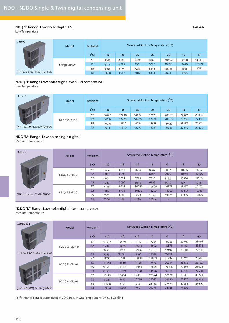
130 131
NDQ - N2DQ Single & Twin digital condensing unit
NDQ ‘L’ Range Low noise digital EVI R404ALow Temperature
27
32
35
-10-15-20-25-30-35-40
43
(oC)
Saturated Suction Temperature (oC)Model Ambient
NDQ18-3LV-C
5146
5119
5103
5060
6311
6225
6174
6037
7476
7331
7245
7014
89688765
8643
8318
1045910198
10041
9623
1238812078
11893
11398
1431613959
13744
-
N2DQ ‘L’ Range Low noise digital twin EVI compressor Low Temperature
27
32
35
-10-15-20-25-30-35-40
43
(oC)
Saturated Suction Temperature (oC)Model Ambient
N2DQ36-3LV-E
10108
10044
10006
9904
12400
12225
12120
11840
14692
14405
14234
13776
1762517221
16978
16331
2055920036
19722
18886
2432723708
23337
22346
2809627380
26951
25806
NDQ ‘M’ Range Low noise single digitalMedium Temperature
27
32
35
-10 50-5-10-15-20
4327
32
35
43
(oC)
Saturated Suction Temperature (oC)Model Ambient
NDQ30-3MX-C
NDQ45-3MX-C
5454
5077
4851
42477188
6812
6587
5986
6556
6098
5824
50958914
8472
8208
7501
7654
7119
6798
594210640
10133
9828
9016
89878364
7990
6993
12806
12220
11869
10932
103209609
9182
804514972
14308
13909
-
1185611054
10574
929117577
16813
16355
-
1339212500
11965
1053720182
19318
18800
-
N2DQ ‘M’ Range Low noise digital twin compressorMedium Temperature
27
32
35
-10 50-5-10-15-20
4327
32
35
43
27
32
35
43
(oC)
Saturated Suction Temperature (oC)Model Ambient
N2DQ60-3MX-D
N2DQ60-3MX-E
N2DQ90-3MX-E
10537
9734
9253
796911154
10343
9856
8558
15216
14237
13650
12084
12640
11684
11110
957913511
12536
11950
10389
18654
17477
16771
14888
14743
13633
12966
1119015868
14728
14044
12220
22091
20716
19891
17691
1728416002
15233
13182
18803
17472
16674
14546
26344
24743
23783
21221
1982518371
17499
1517321737
20217
19304
16871
30597
28770
2767424751
2274521122
20148
-25212
23489
22456
19700
35660
33557
32295
28929
2566623872
22796
-28686
26762
25608
2253040723
38343
36915
-
Performance data in Watts rated at 20oC Return Gas Temperature, 0K Sub Cooling
(H) 1192 x (W) 2260 x (D) 600
Case E
Case C
(H) 1078 x (W) 1128 x (D) 505
Case D & E
(H) 1192 x (W) 1560 x (D) 600
(H) 1192 x (W) 2260 x (D) 600
Case C
(H) 1078 x (W) 1128 x (D) 505
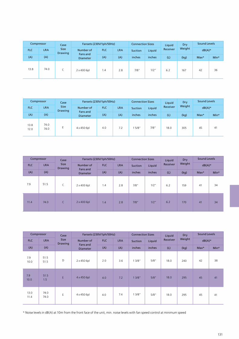
130 131
FLC LRA
(A) (A)
Compressor
FLC LRA
(A) (A) inches inches (L) (kg)
DryWeight
Max* Min*
dB(A)*
Sound Levels
1/2” 6.274.0 C 2 x 400 6pl 1.4 2.8 7/8” 167 42 36
LiquidSuction
CaseSize
DrawingNumber of Fans and Diameter
Connection Sizes LiquidReceiver
Fansets (230V/1ph/50Hz)
13.8
FLC LRA
(A) (A)
Compressor
FLC LRA
(A) (A) inches inches (L) (kg)
DryWeight
Max* Min*
dB(A)*
Sound Levels
7/8” 18.074.074.0 E 4 x 450 6pl 4.0 7.2 1 5/8” 305 45 41
LiquidSuction
CaseSize
DrawingNumber of Fans and Diameter
Connection Sizes LiquidReceiver
Fansets (230V/1ph/50Hz)
13.812.0
FLC LRA
(A) (A)
Compressor
FLC LRA
(A) (A) inches inches (L) (kg)
DryWeight
Max* Min*
dB(A)*
Sound Levels
1/2”
1/2”
6.2
6.2
51.5
74.0
C
C
2 x 400 6pl
2 x 400 6pl
1.4
1.4
2.8
2.8
7/8”
7/8”
159
170
41
41
34
34
LiquidSuction
CaseSize
DrawingNumber of Fans and Diameter
Connection Sizes LiquidReceiver
Fansets (230V/1ph/50Hz)
11.4
7.9
FLC LRA
(A) (A)
Compressor
FLC LRA
(A) (A) inches inches (L) (kg)
DryWeight
Max* Min*
dB(A)*
Sound Levels
5/8”
5/8”
5/8”
18.0
18.0
18.0
51.551.5
51.51.5
74.074.0
D
E
E
2 x 450 6pl
4 x 450 6pl
4 x 450 6pl
2.0
4.0
4.0
3.6
7.2
7.4
1 3/8”
1 3/8”
1 3/8”
240
295
295
42
45
45
38
41
41
LiquidSuction
CaseSize
DrawingNumber of Fans and Diameter
Connection Sizes LiquidReceiver
Fansets (230V/1ph/50Hz)
7.910.0
13.011.4
7.910.0
* Noise levels in dB(A) at 10m from the front face of the unit, min. noise levels with fan speed control at minimum speed
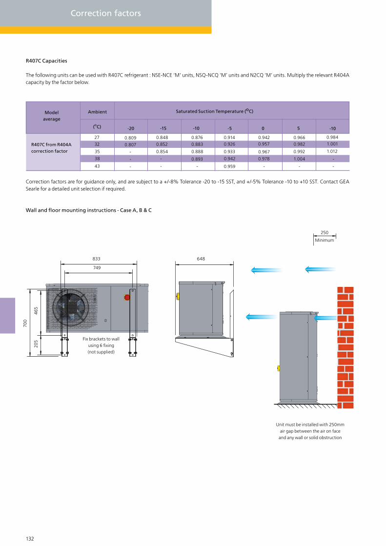
132 133
Correction factors
R407C Capacities
The following units can be used with R407C refrigerant : NSE-NCE ‘M’ units, NSQ-NCQ ‘M’ units and N2CQ ‘M’ units. Multiply the relevant R404A capacity by the factor below.
-10 50-5-10-15-20
27
32
35
38
43
(oC)
Saturated Suction Temperature (oC)Ambient
0.809
0.807
-
-
-
0.848
0.852
0.854
-
-
0.876
0.883
0.888
0.893
-
0.9140.926
0.933
0.942
0.959
0.9420.957
0.967
0.978
-
0.9660.982
0.992
1.004
-
0.9841.001
1.012
-
-
Modelaverage
R407C from R404Acorrection factor
Correction factors are for guidance only, and are subject to a +/-8% Tolerance -20 to -15 SST, and +/-5% Tolerance -10 to +10 SST. Contact GEA Searle for a detailed unit selection if required.
Wall and floor mounting instructions - Case A, B & C
833 648
205
749
465
700
Fix brackets to wallusing 6 fixing (not supplied)
Unit must be installed with 250mm air gap between the air on face
and any wall or solid obstruction
250
Minimum
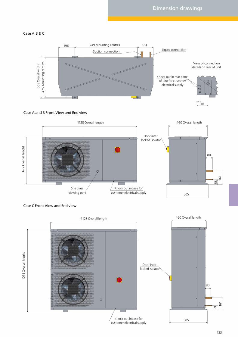
132 133
Dimension drawings
Knock out inbase for customer electrical supply
Site glass viewing port
Knock out in rear panel of uint for customer
electrical supply
Case A,B & C
Case A and B Front View and End view
749 Mounting centres
505
Ove
rall
wid
th47
5 M
ount
ing
cent
res
196
Suction connection Liquid connection
View of connection details on rear of unit
36138
672
Ove
r all
hieg
ht
184
1128 Overall length
Door inter locked isolator
460 Overall length
505
80
161
58
Case C Front View and End view
Knock out inbase for customer electrical supply
1078
Ove
r all
hieg
ht
1128 Overall length
Door inter locked isolator
460 Overall length
505
80
161
59

134 135
Dimension drawings
Case D
810 Fixing centres
600
Ove
rall
wid
th
570
Fix
ing
cent
res
1560 Overall length
4 Mounting holesfor M8 fixing bolts
15.0
375 375
15.0
1192
Ove
rall
heig
ht
Control access
Compressor access
Sight glass viewing port
465
483
180
80
Liquid
Suction

134 135
Case E
465
483
180
80
Liquid
Suction
380
2260 Overall length
750 Fixing centres 750 Fixing centres 380
6 Mounting holesfor M8 fixing bolts
Control access
Compressor access
Sight glass viewing port 80
1192
Ove
rall
heig
ht
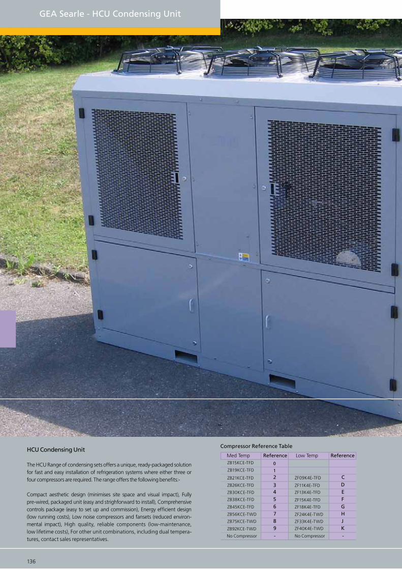
136 137
GEA Searle - HCU Condensing Unit
ZB15KCE-TFD
ZB30KCE-TFD
ZB26KCE-TFD
ZB21KCE-TFD
ZB19KCE-TFD
ZB92KCE-TWD
ZB75KCE-TWD
ZB56KCE-TWD
ZB45KCE-TFD
ZB38KCE-TFD
No Compressor
ZF13K4E-TFD
ZF11K4E-TFD
ZF09K4E-TFD
ZF40K4E-TWD
ZF33K4E-TWD
ZF24K4E-TWD
ZF18K4E-TFD
ZF15K4E-TFD
No Compressor
0
9876543
21
- -
KJHGFEDC
Med Temp Reference Low Temp ReferenceHCU Condensing Unit
The HCU Range of condensing sets offers a unique, ready-packaged solution for fast and easy installation of refrigeration systems where either three or four compressors are required. The range offers the following benefits:-
Compact aesthetic design (minimises site space and visual impact), Fully pre-wired, packaged unit (easy and strighforward to install), Comprehensive controls package (easy to set up and commission), Energy efficient design (low running costs), Low noise compressors and fansets (reduced environ-mental impact), High quality, reliable components (low-maintenance, low lifetime costs), For other unit combinations, including dual tempera-tures, contact sales representatives.
Compressor Reference Table

136 137
HCU 5 5 E E - V 2 08 - L
Compressor No 1 reference
Compressor No 2 reference
L = Left R = Right (Pipe connections viewed from front (compressor door side of unit)
Compressor No 3 reference)
Compressor No 4 reference (Refer to compressor reference table)Air Flow - V = Vertical H = Horizontal R = Recirculatory
No of fans
Motor Poles 12, 08 or 06
Various combinations of 3 or 4 Copeland Compliant scroll compressors for low or high temperature applications.
Compressor rotalock valves for quick and easy maintenance.
In-built oil management system - high pressure combined coalescing separator/ reservoir with individual oil level regulators.
Oil separator shut-off valves for easy filter replacement.
Spare separator filter supplied loose with unit. Crankcase heaters as standard.
Vibration eliminators on compressor suction and discharge lines.
Suction line ball valve and filter with replaceable core.
Liquid line replaceable core drier with fitted core and replacement.
Liquid line three-way valve enabling filter bypass for easy core change.
Electrical controls
Control components located in easily accessible separate front enclosure.
24V control system.
Modulating fan speed control maintains head pressure in low ambient temperatures. Compressor contactors and thermal overload, incorporating short circuit protection, and individual compressor isolation.
Individual compressor short cycle prevention function.
Mains isolator and system HP/LP switch (manual/ auto).
Overview
Suitable for use with R404A , R507 and R407C on medium temperature units (other refrigerants on application).
Two or three fans (two fans only on 12 - pole) 6, 8 or 12-pole motors for low-noise operation.
Choice of three air-flow configurations for siting units internally or externally.
Condenser coil with vinyl coated aluminium fins for extended life. Optional copper fin coil.
Integral liquid sub-cooling section to enhance performance.
Removable doors and access panels for easy maintenance.
35 litre liquid receiver with fitted PRV. Options for Twin PRV, Twin burst disc, sightglass, low level indicator.
Rotalock valves on all compressors and receivers for easy maintenance.
Fully weatherproof, grey gloss painted, pre-galvanized steel casing.
Acoustically lined compressor housing for minimal noise break-out.
CE marked and manufactured under B EN ISO 9001 Quality Assurance.
Units can be supplied with left or right handed connections.
Forklift channels for ease of lifting.
Compressor and System
Integral, separate acoustically lined compressor housing with forced extraction cooling.
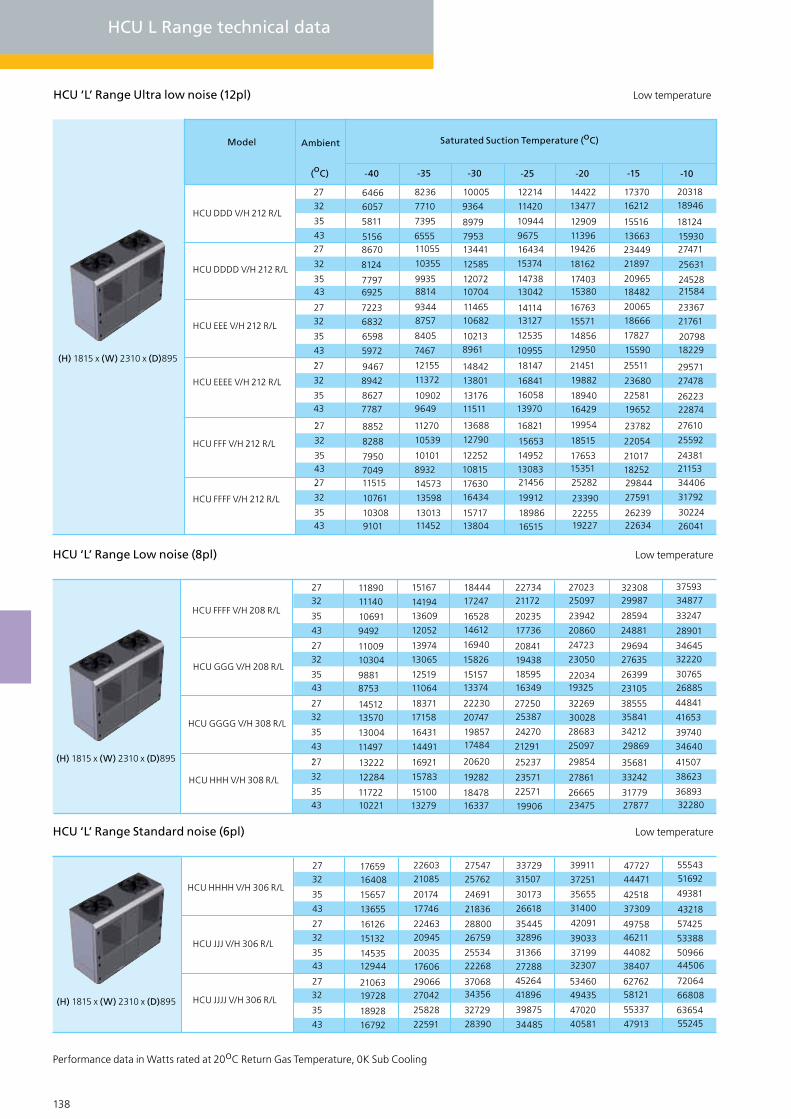
138 139
HCU L Range technical data
HCU ‘L’ Range Ultra low noise (12pl) Low temperature
HCU ‘L’ Range Low noise (8pl) Low temperature
HCU ‘L’ Range Standard noise (6pl) Low temperature
Performance data in Watts rated at 20oC Return Gas Temperature, 0K Sub Cooling
HCU FFFF V/H 208 R/L
HCU GGG V/H 208 R/L
HCU GGGG V/H 308 R/L
HCU HHH V/H 308 R/L
2732
35
43
2732
3543
2732
35
43
27
32
3543
16921
15167
14194
13609
12052
13974
13065
1251911064
18371
17158
16431
14491
15783
1510013279
1844417247
1652814612
16940
15826
1515713374
22230
20747
1985717484
20620
19282
1847816337
2273421172
20235
17736
20841
19438
1859516349
2725025387
24270
21291
25237
23571
22571
19906
2702325097
23942
20860
24723
23050
2203419325
32269
30028
28683
25097
29854
27861
2666523475
3230829987
28594
24881
29694
27635
26399
23105
3855535841
34212
29869
35681
33242
3177927877
3759334877
33247
28901
3464532220
30765
44841
41653
39740
34640
41507
38623
3689332280
11890
11140
10691
9492
11009
10304
98818753
1451213570
13004
11497
13222
12284
1172210221
26885
HCU HHHH V/H 306 R/L
HCU JJJ V/H 306 R/L
HCU JJJJ V/H 306 R/L
2732
35
43
2732
3543
2732
35
43
22603
21085
20174
17746
2246320945
20035
17606
2906627042
25828
22591
27547
25762
24691
21836
28800
26759
2553422268
3706834356
32729
28390
33729
31507
30173
26618
3544532896
31366
27288
45264
41896
39875
34485
39911
37251
35655
31400
42091
39033
3719932307
53460
49435
47020
40581
4772744471
42518
37309
4975846211
44082
38407
6276258121
55337
47913
5554351692
49381
43218
57425
53388
5096644506
72064
66808
6365455245
1765916408
15657
13655
16126
15132
1453512944
2106319728
18928
16792
HCU DDD V/H 212 R/L
HCU DDDD V/H 212 R/L
HCU EEE V/H 212 R/L
HCU EEEE V/H 212 R/L
27
32
35
-10-15-20-25-30-35-40
4327
32
3543
2732
35
43
27
32
3543
(oC)
Saturated Suction Temperature (oC)Model Ambient
6466
6057
5811
51568670
8124
77976925
7223
6832
6598
5972
9467
8942
8627
7787
8236
7710
7395
655511055
10355
99358814
9344
8757
8405
7467
12155
11372
109029649
10005
9364
8979
795313441
12585
1207210704
1146510682
102138961
14842
13801
1317611511
12214
11420
10944
9675
16434
15374
1473813042
1411413127
12535
10955
18147
16841
16058
13970
14422
13477
12909
1139619426
18162
1740315380
16763
15571
14856
12950
21451
19882
18940
1737016212
15516
13663
23449
21897
2096518482
20065
18666
17827
15590
25511
23680
22581
19652
2031818946
18124
1593027471
25631
2452821584
23367
21761
2079818229
29571
27478
2622322874
HCU FFF V/H 212 R/L
27
32
3543
8852 11270 13688 16821 19954 23782 27610
25592
2438121153
22054
21017
18252
18515
1765315351
15653
14952
13083
12790
12252
10815
10539
10101
8932
8288
7950
7049
16429
HCU FFFF V/H 212 R/L
27
32
3543
14573
13598
1301311452
1763016434
1571713804
21456
19912
18986
16515
25282
23390
2225519227
29844
27591
2623922634
34406
31792
30224
26041
11515
10761
103089101
(H) 1815 x (W) 2310 x (D)895
(H) 1815 x (W) 2310 x (D)895
(H) 1815 x (W) 2310 x (D)895
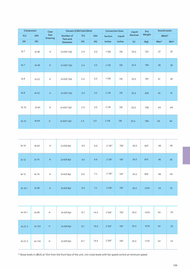
138 139
3x 12
4x 12
3x 16.1
4x 64
3x 74
4x 74
3x 99
H
H
H
H
2x 630 8pl
2x 630 8pl
3x 630 8pl
3x 630 8pl
4.0
4.0
6.0
6.0
6.6
6.6
7.2
7.2
2 1/8”
2 1/8”
2 1/8”
2 5/8”
7/8”
7/8”
7/8”
7/8”
35.0
35.0
35.0
35.0
847
810
855
1079
48
46
48
54
46
42
44
53
4x 10
3x 22.3
4x 22.3
4x 99
3x 134
4x 134
H
H
H
3x 630 6pl
3x 630 6pl
3x 630 6pl
8.7
8.7
8.7
14.4
14.4
14.4
2 5/8”
2 5/8”
2 5/8”
7/8”
7/8”
7/8”
35.0
35.0
35.0
1079
1079
1179
54
54
54
53
53
53
4x 16.1
* Noise levels in dB(A) at 10m from the front face of the unit, min noise levels with fan speed control at minimum speed
FLC LRA
(A) (A)
Compressor
FLC LRA
(A) (A) inches inches (L) (kg)
DryWeight
Max* Min*
dB(A)*
Sound Levels
4x 7
3x 8
4x 8
3x 46
4x 46
3x 52
4x 52
H
H
H
H
2x 630 12pl
2x 630 12pl
2x 630 12pl
2x 630 12pl
2.4
2.4
2.4
2.4
3.0
3.0
3.0
3.0
1 5/8
2 1/8
1 5/8
2 1/8
7/8
7/8
7/8
7/8
35.0
35.0
35.0
35.0
757
790
787
830
37
38
41
42
35
36
40
41
3x 7
3x 10 3x 64 H 2x 630 12pl 2.4 3.0 2 1/8 7/8 35.0 790 44 44
4x 10 4x 64 H 2x 630 12pl 2.4 3.0 2 1/8 7/8 35.0 790 44 44
LiquidSuction
CaseSize
DrawingNumber of Fans and Diameter
Connection Sizes LiquidReceiver
Fansets (230V/1ph/50Hz)

140 141
HCU 333 V/H 212 R/L
27
32
35
1050-5-10-15-20
43
(oC)
Saturated Suction Temperature (oC)Model Ambient
13932
12855
12210
10491
16871
15599
14836
12800
19813
18343
17461
15109
23508
21780
20744
17979
35971
33408
31871
27770
27203
25217
24026
20849
31587
29313
27948
24310
HCU ‘M’ Range Ultra low noise (12pl) Medium temperature R404A
HCU ‘M’ Range Low noise (8pl) Medium temperature
Performance data in Watts rated at 20oC Return Gas Temperature, 0K Sub Cooling
HCU 6666 V/H 306 R/L
HCU 777 V/H 306 R/L
HCU 7777 V/H 306 R/L
HCU 888 V/H 306 R/L
27
32
35
43
27
32
3543
32021 38861 45700 54062 8214562424 72285
66973
63786
55288
64311
59604
56779
60177 69751 80878 92004 104622 11724050604
46859
44612
38621
108462
103195
-
96750
92027
-
85038
80859
-
74727
71037
61197
64416
61216
52680
55638
52914
45651
49247
8018574128
70494
60804
85874
79655
75923
65972
57805
55033
47642
55385
51318
4887842371
6963864358
61191
52743
74733
69289
66023
57313
76142
72540
62934
73237
67889
6468056124
90731
83898
79798
68865
97015
90020
85823
-
50025
47603
4114347959
44449
4234336728
60640
56057
53308
45977
65241
60468
57605
49969
42246
40173
34645
40532
37580
3580831084
5164147757
45426
39211
55748
51647
49187
42625
35929
34171
29480
34492
31994
3049626500
4414340844
38865
33587
47773
44303
42222
36670
29613
28168
24316
28451
26409
2518421916
3664533932
32304
27963
39798
36959
35256
30715
27
32
35
43
27
32
3543
HCU 8888 V/H 306 R/L
2732
35
43
22823 26837 31921 4916337004 4308440014
38172
33261
38959
36253
34628
32205 37792 44591 51390 59376 67362
62519
59613
51865
55065
52479
45582
47611
45344
39298
41265
39270
33948
34919
33195
28598
29738
28258
24312
30298
18809
29056 53952 6128334160 40391 46621
43161
41085
35549
58163
53696
51015
43866
37366
35552
30713
50672
46743
44386
38099
31571
30018
25876
43181
3979137756
32331
56794
54101
46918
75267
69557
66131
-
49978
47593
41234
66715
61626
5857350431
26859
25541
22026
36919
3402732291
27664
17374
16513
14217
16852
15555
14777
12702
21754
20031
18998
16242
20413
18863
1793315454
26617
24557
23321
20026
23952
22147
21064
18176
30656
2826226826
22996
49095
45593
43492
37888
46339
43039
41059
35779
34331
32728
28451
33418
31018
29578
25737
42353
39230
37356
32358
39923
37044
35316
30709
45697
43617
38071
44500
41487
3967934858
55838
5195749628
43418
52755
49035
46802
40849
29600
28208
24495
28791
26690
2543022070
36641
33894
32246
27851
34543
32016
30499
26455
24869
23688
20539
24163
22363
21282
18402
30928
28558
27136
23345
29163
26987
25682
22201
21122
20101
17378
20507
18959
18030
15552
26341
24295
23067
19793
24788
22925
21808
18828
HCU 3333 V/H 208 R/L
HCU 444 V/H 208 R/L
HCU 4444 V/H 208 R/L
HCU 555 V/H 208 R/L
27
32
35
43
27
32
35
43
27
32
35
43
27
32
35
43
HCU 5555 V/H 308 R/L
27
32
35
43
HCU 666 V/H 308 R/L
HCU 6666 V/H 308 R/L
27
32
35
43
2732
35
43
HCU ‘M’ Range Standard noise (6pl) Medium temperature
HCU L Range technical data
(H) 1815 x (W) 2310 x (D)895
(H) 1815 x (W) 2310 x (D)895
(H) 1815 x (W) 2310 x (D)895
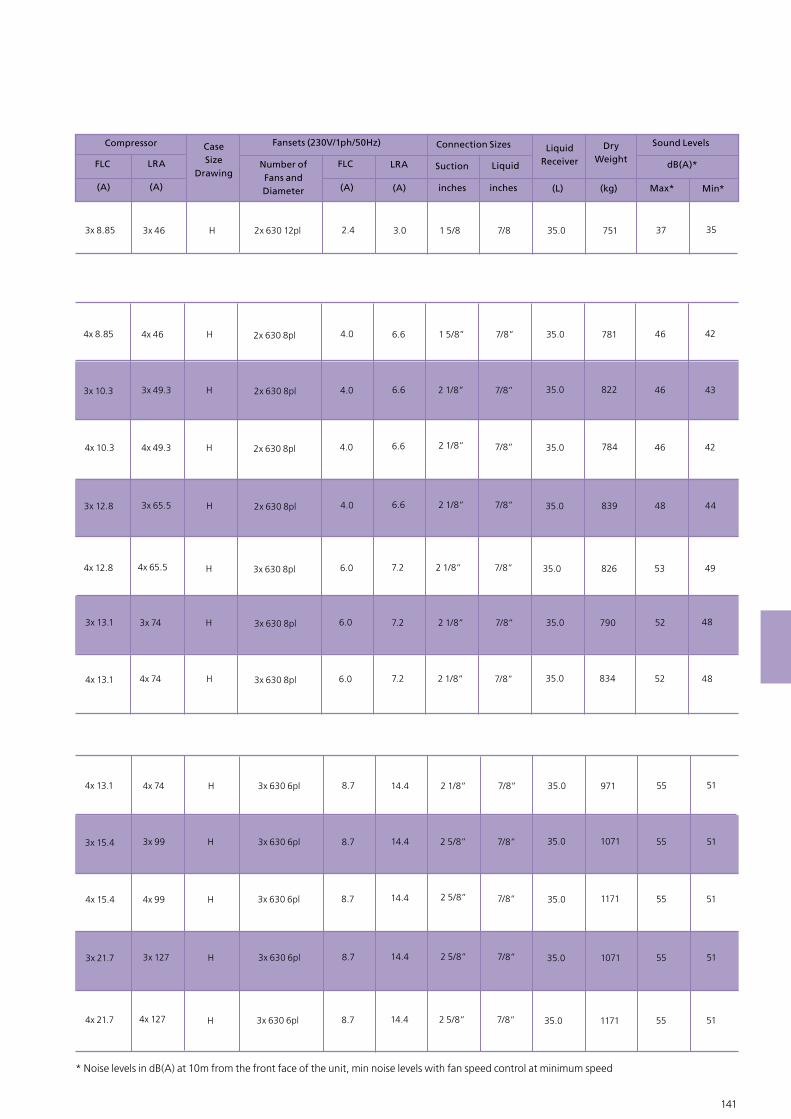
140 141
* Noise levels in dB(A) at 10m from the front face of the unit, min noise levels with fan speed control at minimum speed
3x 10.3
4x 10.3
3x 12.8
4x 46
3x 49.3
4x 49.3
3x 65.5
H
H
H
H
4.0
4.0
4.0
4.0
6.6
6.6
6.6
6.6
1 5/8”
2 1/8”
2 1/8”
2 1/8”
7/8”
7/8”
7/8”
7/8”
35.0
35.0
35.0
35.0
781
822
784
839
46
46
46
48
42
43
42
44
4x 8.85
4x 12.8 4x 65.5 H 6.0 7.2 2 1/8” 7/8” 35.0 826 53 49
4x 13.1
3x 74
4x 74
H
H
6.0
6.0
7.2
7.2
2 1/8”
2 1/8”
7/8”
7/8”
35.0
35.0
790
834
52
52
48
48
3x 13.1
2x 630 8pl
2x 630 8pl
2x 630 8pl
2x 630 8pl
3x 630 8pl
3x 630 8pl
3x 630 8pl
3x 15.4
4x 15.4
3x 21.7
4x 74
3x 99
4x 99
3x 127
H
H
H
H
3x 630 6pl
3x 630 6pl
3x 630 6pl
3x 630 6pl
8.7
8.7
8.7
8.7
14.4
14.4
14.4
14.4
2 1/8”
2 5/8”
2 5/8”
2 5/8”
7/8”
7/8”
7/8”
7/8”
35.0
35.0
35.0
35.0
971
1071
1171
1071
55
55
55
55
51
51
51
51
4x 13.1
4x 21.7 4x 127 H 3x 630 6pl 8.7 14.4 2 5/8” 7/8” 35.0 1171 55 51
2x 630 12pl
Physical data
FLC LRA
(A) (A)
Compressor
FLC LRA
(A) (A)
Fansets (230V/1ph/50Hz)
inches inches (L) (kg)
DryWeight
Max* Min*
dB(A)*
Sound Levels
3x 46 H 2.4 3.0 1 5/8 7/8 35.0 751 37 353x 8.85
LiquidSuction
CaseSize
DrawingNumber of Fans and Diameter
Connection Sizes LiquidReceiver
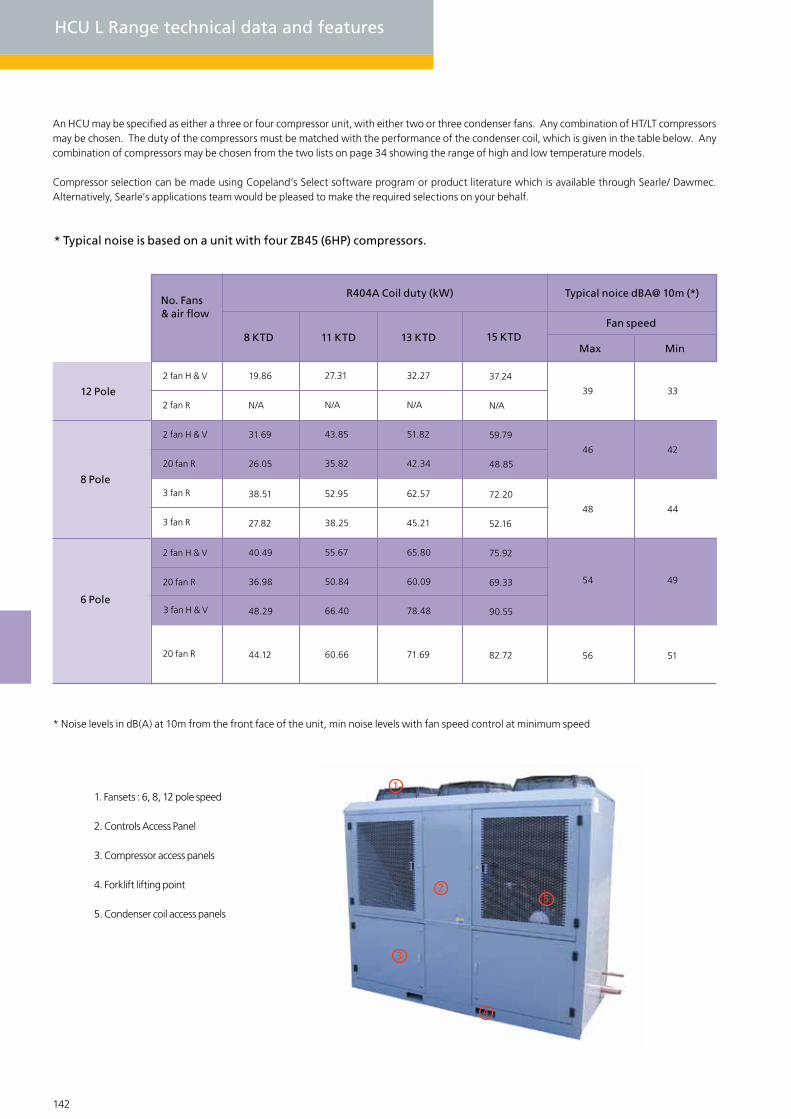
142 143
An HCU may be specified as either a three or four compressor unit, with either two or three condenser fans. Any combination of HT/LT compressors may be chosen. The duty of the compressors must be matched with the performance of the condenser coil, which is given in the table below. Any combination of compressors may be chosen from the two lists on page 34 showing the range of high and low temperature models.
Compressor selection can be made using Copeland’s Select software program or product literature which is available through Searle/ Dawmec. Alternatively, Searle’s applications team would be pleased to make the required selections on your behalf.
* Typical noise is based on a unit with four ZB45 (6HP) compressors.
* Noise levels in dB(A) at 10m from the front face of the unit, min noise levels with fan speed control at minimum speed
HCU L Range technical data and features
2 fan H & V
2 fan R
2 fan H & V
20 fan R
3 fan R
3 fan R
2 fan H & V
20 fan R
3 fan H & V
20 fan R
19.86
N/A
31.69
26.05
38.51
27.82
40.49
36.98
48.29
44.12
27.31
N/A
43.85
35.82
52.95
38.25
55.67
50.84
66.40
60.66
32.27
N/A
51.82
42.34
62.57
45.21
65.80
60.09
78.48
71.69
37.24
N/A
59.79
48.85
72.20
52.16
75.92
69.33
90.55
82.72
39
46
48
54
56
33
42
44
49
51
12 Pole
8 Pole
6 Pole
No. Fans & air flow
8 KTD 11 KTD 13 KTD 15 KTDMax Min
Fan speed
Typical noice dBA@ 10m (*)R404A Coil duty (kW)
1
2
3
4
5
1. Fansets : 6, 8, 12 pole speed
2. Controls Access Panel
3. Compressor access panels
4. Forklift lifting point
5. Condenser coil access panels

142 143
1
2
3
1
2
1. Suction and discharge vibration eliminators
2. Multiple scroll compressors including rotalock valves
1. Individual compressor oil return shut-off valves
2. Individual compressor oil float regulators
3. High pressure combined coalescing separator/ reservoir complete with replaceable filter
1. Receiver outlet rotalock valves
2. 35 litre liquid receiver
3.3-way valve for filter bypass for ease of core changes
4. Liquid line sight glass
1. Compressor step controller
2. Compressor overloads/ manual motor starters
3. Compressor contactors
4. Fault relays
5. 24 volt transformer
6. Mains isolator complete with 100amp auxillary connection for customer use
1
23
4
1
2
3
4
5
6

144 145
HCU - Horizontal air flow 2 & 3 fan models
630 1050 fan centres 630
2310 O/All length
22
150
22
150
180180 540 Fork lift gap
2256 Mounting centres
2300 Base length
Suction 2 connection
Liquid out connection
Suction 1 connectionLH unit connection positions
RH unit connection positions
896 Overall width
1375
Fan
cen
tre
heig
ht
1815
Ove
rall
heig
ht
322
252
170
843 Mounting centres
889 Base length2323
430 725 fan centres 430
2310 O/All length
22
150
22
150
180180 540 Fork lift gap
2256 Mounting centres
2300 Base length
Suction 2 connection
Liquid out connection
Suction 1 connectionLH unit connection positions
RH unit connection positions
896 Overall width
1375
Fan
cen
tre
heig
ht
1815
Ove
rall
heig
ht
322
252
170
843 Mounting centres
889 Base length
2323
725 fan centres
HCU Dimension drawings
H
4 MNTG holes O 12.00
4 MNTG holes O 12.00
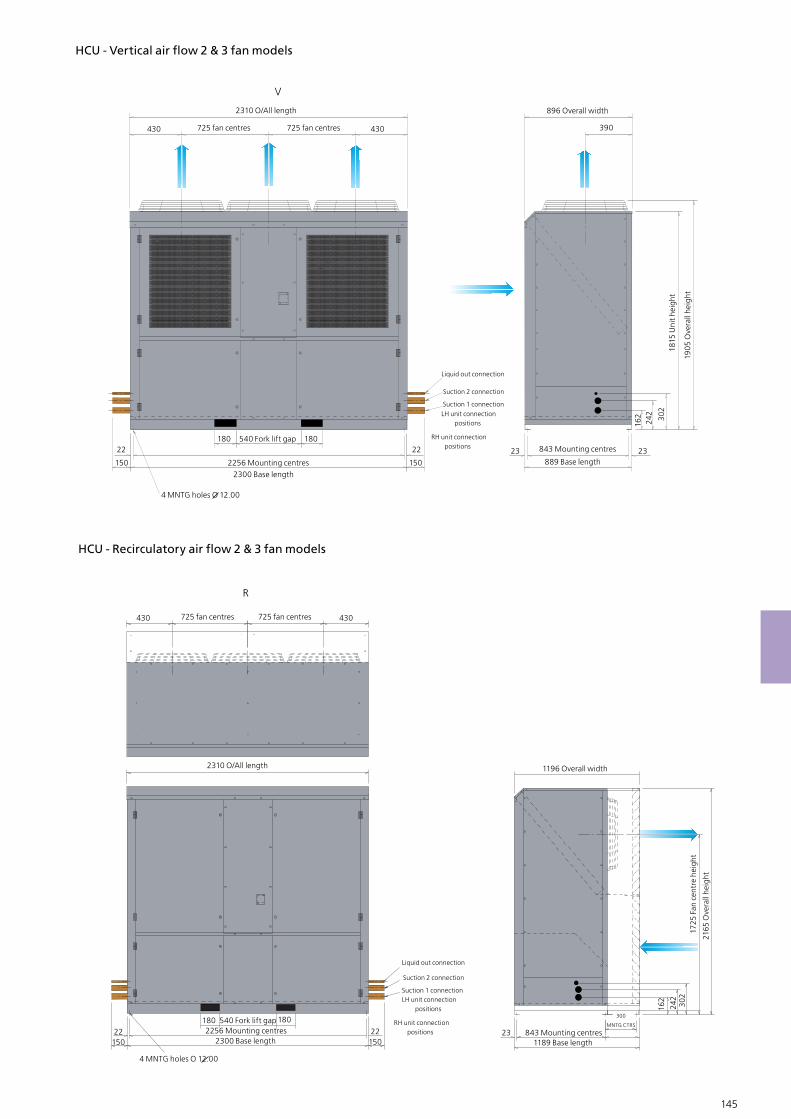
144 145
HCU - Vertical air flow 2 & 3 fan models
V
430 725 fan centres 430
2310 O/All length
22
150
22
150
180180 540 Fork lift gap
2256 Mounting centres2300 Base length
Suction 2 connection
Liquid out connection
Suction 1 connectionLH unit connection positions
RH unit connection positions
725 fan centres
4 MNTG holes O 12.00
896 Overall width
1815
Uni
t hei
ght
1905
Ove
rall
heig
ht
302
242
162
843 Mounting centres
889 Base length2323
390
2310 O/All length
22150
180180 540 Fork lift gap2256 Mounting centres
2300 Base length
Suction 2 connection
Liquid out connection
Suction 1 connectionLH unit connection positions
RH unit connection positions
4 MNTG holes O 12.00
1196 Overall width
1725
Fan
cen
tre
heig
ht
2165
Ove
rall
heig
ht
302
242
162
843 Mounting centres1189 Base length
300
MNTG CTRS
2322150
430 725 fan centres 430725 fan centres
R
HCU - Recirculatory air flow 2 & 3 fan models
GEA Searle’s wide range of commercial unit coolers guarantee the continued excellence of our product range on terms of innovation, design and performance to offer the ideal cooler at a competitive price. They are the 1st choice product for their proven design and reliability, the range comes with many benefits which is often uti-lised across many industries the applications include small and large cold rooms and cabinets, warehouses, food nstorage and prepara-tion rooms, freezers and blast freezing.
GEA Searle - Commercial Air Coolers
146 147

General range features
Motors & Fansets
GEA Searle selects the optimum combination of motors and fans to deliver the best performance for the cooler size and application range. All motors and fansets are verified for power input and air volume in our Research & Development department. Specific motor data details are provided in the relevant section for each cooler type.
EC
EC fansets offer the optimum in energy efficient performance combined with low noise levels and high reliability. The KEC Cooler range uses EC fan-sets as standard making it the most energy efficient cooler product availa-ble. Energy usage can be less than 50% of that of similar products, resulting in a product with a reduced payback period. Additional benefits include;-
Internal motor protection Long service life High efficiency across the full operating range
For more information on EC fansets please see the back of this catalogue Energy Efficient Fansets”
Casework
The standard GEA Searle cooler casework is white powder coated, oven cured at 180oC to provide a hard durable finish. The JG, KLe and NS cool-ers are manufactured using aluminium casework, while the TEC, LDF, KEC, KMe and DSR all utilise galvanised steel casing.
Blygold Coating (Optional)
GEA Searle has installed a purpose built coating facility to apply the Blygold coil protection coating to any size of coil. Blygold with stands almost all chemical vapour exposure conditions and is ideal for the following applica-tion areas :-
Corrosive environments Aggressive industrial areas
The duties presented in the specification tables are nominal. Tests are coducted in accordance with EN 328 under dry conditions which allows peformance to stabiilise and permits measurement over a prolonged period. The wet catalogue capacities are calculated from the dry capacities using the ratios given in the Eurovent Standard 7/C/001.
*Dew point capacity factors for refrigerants with high glide apply only at the nominal rating condition. Mid point factors can be used for all condi-tions. Refrigerant Charge Densities based on 25% of the internal volume being liquid.
146 147
Refrigeration R404A R134a R507A R407CR407A
Capacity factor (dew point, DT1)
Capacity factor (mid point, DT1)
Refrigerant charge density (kg/dm3)
1.00
0.97
0.312
0.91
0.91
0.338
0.97
0.97
0.313
1.18*
0.91
0.332
135*
1.01
0.332

148 149
Range benefits
The GEA Searle range of commercial unit coolers combine versatility and aesthetic design with consistent performance to offer the ideal cooler at a competitive price. They are typically the 1st choice product for the following applications due to their proven design and reliability :-
Cold rooms Food storage Food preparation Cool cabinets
GEA Searle coolers are approved for many supermarkets across the world and are used extensively in convenience stores, commercial refrigeration applications and many industrial & agricultural projects.
Selection software
Due to the large number of models available and the range of alternative refrigerants, selection of the optimum cooler is best performed using the latest Searle Selection Soft-ware. The software can be obtained either as a CD, direct from your GEA Searle repre-sentative or dowloaded from the GEA Searle website, where it is also possible to view all brochures and installation & maintenance data.
Energy efficient
With the increasing importance of energy efficiency as part of the selection criteria, the new GEA Searle coolers utilise fansets which offer significant energy savings over traditional motor assemblies. The KEC cooler has high efficiency EC fans as standard across the range.
Assured performance
All our commercial unit coolers where applicable are certified under the Eurovent “ Certify All” programme to guarantee that every unit will perform as specified.
Availability
Many of the models in the commercial unit cooler ranges are available ex-stock from your local distributor, with backup stocks held at the UK manufacturing plant centre.
Backing our beliefs
We offer 24 months warranty on all products in the range, with 24 months warranty on all KEC coolers (subject to standard Terms & Conditions of Sale and excluding corrosion through misapplication).
Commercial Air Coolers
Mo
del
s
Co
nfi
gu
rati
on
Euro
ven
t
JG
TEC*
LDF
NS
KEC*
KMe
DSR*
1 - 3
1 - 3
1 - 3
1 - 4
1 - 3
1 - 4
1 - 4
No
fan
s
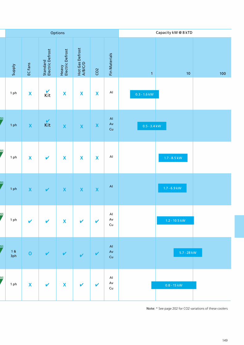
148 149
Sup
ply
Ho
t G
as D
efro
stA
/B/C
/D
EC F
ans
Stan
dar
dEl
ectr
ic D
efro
st
CO
2
1 10 100
1 ph
1 &3ph
Capacity kW @ 8 kTD
0.8 - 15 kW
0.3 - 1.6 kWAI
AI
AI
Av
Cu
Options
Hea
vyEl
ectr
ic D
efro
st
Fin
Mat
eria
ls
AI
AI
Av
Cu
AI
Av
Cu
AI
Av
Cu
1 ph
1 ph
1 ph
1 ph
1 ph
Kit
Kit 0.5 - 3.4 kW
1.7 - 8.5 kW
1.2 - 10.5 kW
5.7 - 28 kW
1.7 - 6.9 kW
Note: * See page 202 for CO2 variations of these coolers

150 151
GEA Searle - JG Air Coolers
JG Unit Coolers
The JG range of eight, cost-effective, small ‘blow through’ unit coolers suitable for both high and low temperature applications. Its ultra low-profile design makes it ideal for use in areas such as reach-in and walk-in cold cabinets and small cold rooms. With an evaporating range of +10°C to - 40°C, the JG range offers nominal capacities from 0.33kW to 1.64kW (R404A at 8K DT1) and will op-erate with low ozone depletion factor refrigerants R404A, R134a, and R507A.
Casework
The casework is aluminium, electrostatically powder painted and
cured at 180°C to ensure an even, flexible and durable white gloss finish. Motors and fans are secured to the fan plate, which can be lowered to provide access to all refrigeration piping, electrical connections and components. An inner drain-tray is fitted to prevent sweating and improve condensate drainage.
Coils
Coils are manufactured from 3/8” OD copper tube (internally grooved to provide an extended inner surface) and aluminium fins. Tubes are mechani-cally expanded to provide a tight interference fit between the aluminium fin collar and the copper tube, giving excellent heat transfer characteristics. Finspacing is 4.3mm. Models 1 to 5 have a single circuit and are suitable for use with an internally equalised expansion valve. Models 6, 7 and 8 have
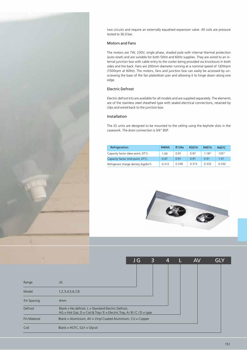
150 151
two circuits and require an externally equalised expansion valve. All coils are pressure tested to 36.0 bar.
Motors and Fans
The motors are 7W, 230V, single phase, shaded pole with internal thermal protection (auto reset) and are suitable for both 50Hz and 60Hz supplies. They are wired to an in-ternal junction box with cable entry to the cooler being provided via knockouts in both sides and the back. Fans are 200mm diameter running at a nominal speed of 1200rpm (1500rpm at 60Hz). The motors, fans and junction box can easily be accessed by un-screwing the base of the fan plate/drain pan and allowing it to hinge down along one edge.
Electric Defrost
Electric defrost kits are available for all models and are supplied separately. The elements are of the stainless steel sheathed type with sealed electrical connections, retained by clips and wired back to the junction box.
Installation
The JG units are designed to be mounted to the ceiling using the keyhole slots in the casework. The drain connection is 3/4” BSP.
J G 3 4 L AV GLY
Fin Material Blank = Aluminium, AV = Vinyl Coated Aluminium, CU = Copper
Coil Blank = HCFC, GLY = Glycol
Fin Spacing 4mm
Defrost Blank = No defrost, L = Standard Electric Defrost, HG = Hot Gas, D = Coil & Tray / E = Electric Tray, A / B / C / D = type
Refrigeration R404A R134a R507A R407CR407A
Capacity factor (dew point, DT1)
Capacity factor (mid point, DT1)
Refrigerant charge density (kg/dm3)
1.00
0.97
0.312
0.91
0.91
0.338
0.97
0.97
0.313
1.18*
0.91
0.332
135*
1.01
0.332
Range JG
Model 1,2,3,4,5,6,7,8

152 153
JG Selection data & Dimensions
Model
JG1JG2
JG3
JG4
JG5
JG6
JG7
JG8
330520
660
800
1000
1210
1360
1640
300470
600
730
910
1100
1240
1490
11
1
1
2
2
3
3
0.0950.081
0.087
0.078
0.159
0.135
0.230
0.205
2.53.0
3.0
3.0
4.0
3.5
4.5
4.0
5049
49
49
52
52
54
54
3838
38
38
76
76
114
114
0.250.25
0.25
0.25
0.50
0.50
0.75
0.75
0.811.63
2.31
3.47
3.05
4.57
4.10
6.14
0.2640.527
0.707
1.060
0.901
1.350
1.174
1.760
90180
240
360
300
460
400
600
275550
700
700
900
900
1000
1000
W W
No.fans
R404A R134a
Capacity (dew point) 8k DT1 Fan/Motor Specifications 230V - 1ph - 50Hz
m3/s m dB (A) W A m2 dm3 gms W
Air volume
Air throw(***)
Noise level(**)
Total PowerInput
TotalFLC
SurfaceArea
Internalvolume
Approx.Ref.
charge
Electricdefrost
Coil Data
Notes:
Rating conditions:The duties shown in this catalogue are at EN 328 Standard Condition 2 (-8oC saturated suction temperature, 0oC air entering). For data on refrigerants not shown, please contact your supplier.
* DT1 is the difference between the entering air temperature and the saturated suction temperature at the outlet of the cooler. ** Noise levels are based on free feld conditions at a distance of 3m. Actual noise levels will depend upon cold store construction, store loading and the number of coolers installed. *** Terminal air velocity 0.25m/s, free air conditions at 10oC. Air throw cannot be considered on absolute value because many factors have a substantial effect on the distance achieved. Total Power Input at Standard Condition 2 (-8oC saturated suction temperature, 0oC air entering).
Options and Spares
Defrost kit for JG1
Defrost kit for JG2
Defrost kit for JG3 & 4
Defrost kit for JG5 & 6
Defrost kit for JG7 & 8
Fan/motor assembly
Fan guard
Drain connection 3/4“ BSPGasket for drain connection
Part Number JG1 JG2 JG3 JG4 JG5 JG6 JG7 JG8Description
G1 - E1
G2 - E1
G3/4 - E1
G5/6 - E1
G7/8 - E1
231 - 920 - 028
244 - 116 - 001
261 - 763 - 006261 - 763 - 007
1
-
-
-
-
1
1
11
-
1
-
-
-
1
1
11
-
-
1
-
-
1
1
11
-
-
1
-
-
1
1
11
-
-
-
1
-
2
2
11
-
-
-
1
-
2
2
11
-
-
-
-
1
3
3
11
-
-
-
-
1
3
3
11
R404A/507AR134a
Rating Conditions
The duties shown in this catalogue are at EN 328 Standard Condition 2 (-8°C saturated suction temperature,0°C air entering).
Correction factors
are provided for calculating duties at other conditions and with alternative refrigerants. Correction Factors (multipy capacity
JG Cooler DT1 - WET

1121335
564
1128
335 335
127
152 153
52558
127
266532
JG 1, 2
JG 3, 4
69058
348.5
697
574
JG 5, 6
86858
437.5875
376 376
127
58
JG 7, 8
JG1JG2
JG3
JG4
JG5
JG6
JG7
JG8
11
1
1
2
2
3
3
4.75.1
6.4
7.2
8.5
9.6
11.5
13.0
3/8”3/8”
3/8”
3/8”
3/8”
3/8”
3/8”
3/8”
3/8”3/8”
3/8”
3/8”
3/8”
1/2”
1/2”
1/2”
3/4”3/4”
3/4”
3/4”
3/4”
3/4”
3/4”
3/4”
Model No. of fansApprox
Dry weight
Refrigeration connections Drainconnection
BSPInlet Outlet
399.2
127
420
59
170 197.6
84
7.5
4.0
20

154 155
GEA Searle - TEC Air Coolers

154 155
TEC Unit Cooler
TEC is a range of nine small ‘blow through’ unit coolers using high efficiency EC fans as stan-dard, providing a significant reduction in energy consumption and therefore running costs. With a wide operating range + 10 °C to -40 °C, the coolers are suitable for both high, medium and low temperature applications in areas such as reach-in and walk - in cold cabinets, small cold rooms and similar situations. Nominal capacities are from 0.52kW to 3.4kW (Standard Condition 2) when used with low ozone depletion refrigerants such as R134a, R404A and R507A.
The TEC range, with 1, 2 or 3 fan configurations, can be either ceiling mounted or wall mount-ed (by using the optional wall mounting kit). The pleasing aesthetic design of the coolers, man-ufactured in galvanised steel and finished with oven cured white epoxy powder paint, comple-ments the working environment as well as providing rigidity and excellent corrosion resistance. The fansets are secured to the hinged fan plate, which can be lowered to provide access to all refrigeration piping and electrical connections and components.
The EC fans are high efficiency, having a power input of only 20W, a 67% saving on the TG shaded pole motor. Motors are suitable for 230V, single phase, 50 / 60 Hz supply, and have internal thermal protection. Fans are pre-wired to an internal junction box with cable entry to the cooler being provided via one of several knock-outs.
Coils are manufactured from 3/8” OD copper tube (internally grooved to provide an extended inner surface) and aluminium fins of type ‘E’. The copper tube is mechanically extended to pro-vide a tight interference fit between the aluminium fin collar and the copper tube, thus giving excellent heat transfer characteristics. The units are available in two fin spacing’s 3.6mm (7 fpi) and 5.1mm (5 fpi). Models TEC1, TEC2 and TEC3 have a single circuit and are suitable for use with an internally equalised expansion valve. Models TEC3.5 to TEC8 are multi - circuited and require an externally equalised expansion valve. All coils are pressure tested to 35.8 bar.
Supply frequency Blank/ Leerfeld = 50Hz, 60 = 60Hz
Fin Material Aluminium
Model 1,2,3,3.5,4,5,6,7,8
Fin Spacing 5 FPI (5.1mm), 7 FPI (3.6mm)
Range TEC
TEC 4 - 5 60

156 157
Notes:
* Capacity quoted at Standard Condition 2 (-8°C saturated suction temperature, 0°C air entering). Total Power Input at Standard Condition 2
For further information please contact your sale repersentative or refer to the selction software online at www.searle .co.uk
7 FP
I (3.
6mm
)5
FPI (
5.1m
m)
TEC1-7TEC2-7TEC3-7TEC3.5-7TEC4-7TEC5-7TEC6-7TEC7-7TEC8-7TEC1-5TEC2-5TEC3-5TEC3.5-5TEC4-5TEC5-5TEC6-5TEC7-5TEC8-5
0.570.891.041.251.722.042.293.023.40.520.841.001.151.611.892.142.763.18
0.520.810.951.141.571.862.082.753.090.470.770.911.051.471.721.952.512.89
540490550590950108010801620173058052058062010101120121016901810
4.54.55.05.05.05.55.56.06.04.54.55.05.05.05.55.56.06.0
202020204040406060202020204040406060
1.52.94.15.45.47.39.710141.12.23.14.14.15.47.37.710
1 x 2751 x 5501 x 7001 x 9001 x 9001 x 10001 x 10001 x 14001 x 14001 x 2751 x 5501 x 7001 x 9001 x 9001 x 10001 x 10001 x 14001 x 1400
0.3950.791.061.351.351.762.342.423.230.3950.791.061.351.351.762.342.423.23
W
Model
R404A
Fanset and Motor
Air throw/(***)
Noise level(**)Power Input
Total surface
area
Internal Volume Ceiling
mountWall
mount
Capacity kW SC2
R134a
m3/h
515050505352515453514950505351495452
2 x 2502 x 2502 x 3252 x 4252 x 4252 x 5752 x 6752 x 10302 x 10302 x 2502 x 2502 x 3252 x 4252 x 4252 x 5752 x 6752 x 10302 x 1030
Optional electric defrost
W
Air volume
m W dBA m2 dm3
TEC Selection data & Dimensions
R404A/507AR134a
TEC Cooler DT1 - WET
Correction Factors
(multipy capacity byappropriate correction factor to give performance at chosen condi-tions)
Rating Conditions
The duties shown in this catalogue are at EN 328 Standard Condition 2 (-8oC saturated suction temperature, 0oC air entering). For data on refrigerants not shown, please contact your supplier.

156 157
TEC1TEC2TEC3TEC3.5TEC4TEC5TEC6TEC7TEC8
111122233
5255256908658651120112015281528
375375375375375375375375375
120120120120120120120120120
550550550550550550550550550
453 (x4)453 (x4)618 (x4)793 (x4)793 (x4)524 (x6)524 (x6)728 (x6)728 (x6)
180180180180180180230180230
Model
A B C
mm
X MinED
No.of
fans
3/83/83/81/21/21/25/87/87/8
10mm 10mm10mm12mm12mm12mm15mm22mm22mm
InletOutlet
Connections
7.38.29.812.013.716.418.524.026.9
Approxdry
weightInchesInches
3/8 3/83/81/21/21/25/87/87/8
mmmm
10mm 10mm10mm12mm12mm12mm15mm22mm22mm
Options - Part numbers of options supplied separately
Part type/ Description TEC1 TEC2 TEC3 TEC3.5/4 TEC4 TEC5 TEC6 TEC7 TEC8
Def
rost
kit
s Ceiling Mounting
Wall Mounting
Wall mounting kits
T2 LTKIT
WT1/2 PAN
WT1/2LTKIT
T3 LTKIT
WT3 PAN
WT3 LTKIT
T3.5/4
WT3.5/4 PAN
WT3.5/4
T5/6LTKIT
WT5 PAN
WT5 LTKIT
WT6 PAN
WT6 LTKIT
T7/8LTKIT
WT7 PAN
WT7/8
WT8 PAN
A
E
A
D
D
B
180C
32
X
7.5
4.0
20
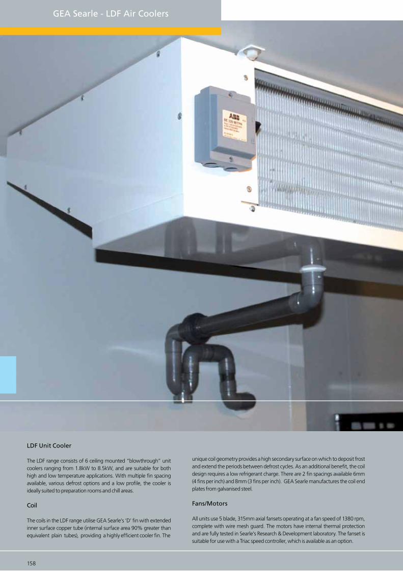
158 159
GEA Searle - LDF Air Coolers
LDF Unit Cooler
The LDF range consists of 6 ceiling mounted “blowthrough” unit coolers ranging from 1.8kW to 8.5kW, and are suitable for both high and low temperature applications. With multiple fin spacing available, various defrost options and a low profile, the cooler is ideally suited to preparation rooms and chill areas.
Coil
The coils in the LDF range utilise GEA Searle’s ‘D’ fin with extended inner surface copper tube (internal surface area 90% greater than equivalent plain tubes), providing a highly efficient cooler fin. The
unique coil geometry provides a high secondary surface on which to deposit frost and extend the periods between defrost cycles. As an additional benefit, the coil design requires a low refrigerant charge. There are 2 fin spacings available 6mm (4 fins per inch) and 8mm (3 fins per inch). GEA Searle manufactures the coil end plates from galvanised steel.
Fans/Motors
All units use 5 blade, 315mm axial fansets operating at a fan speed of 1380 rpm, complete with wire mesh guard. The motors have internal thermal protection and are fully tested in Searle’s Research & Development laboratory. The fanset is suitable for use with a Triac speed controller, which is available as an option.
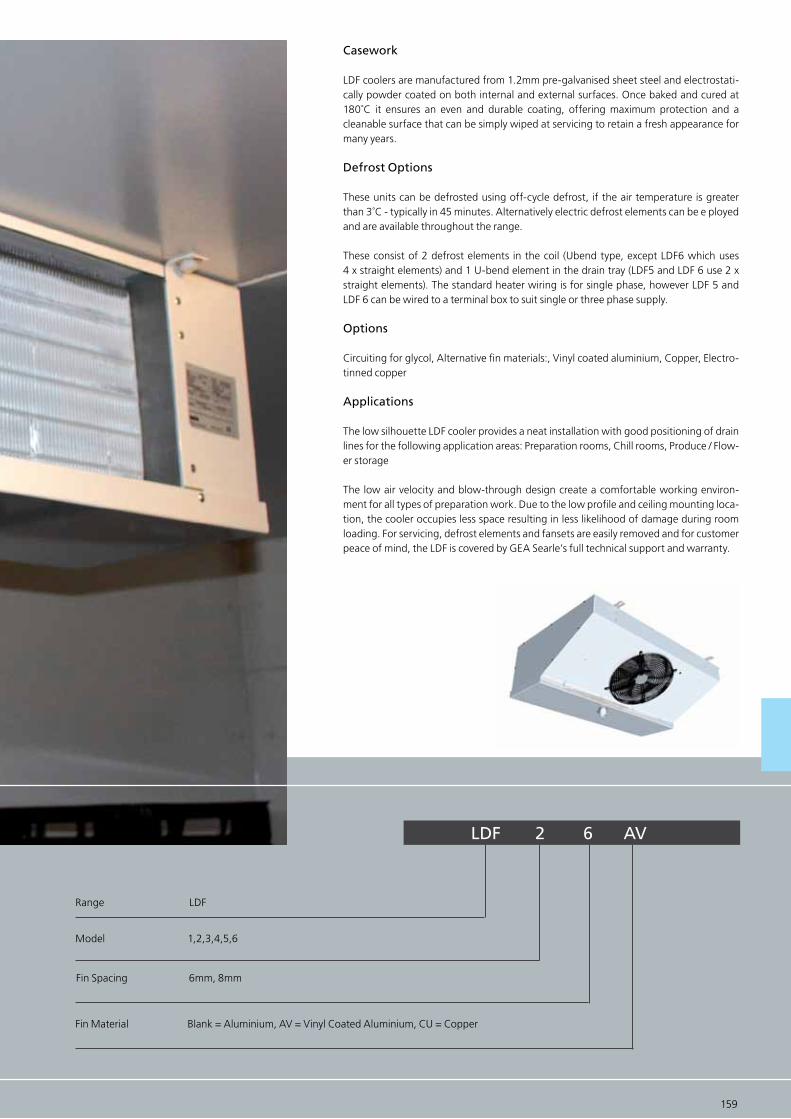
158 159
Casework
LDF coolers are manufactured from 1.2mm pre-galvanised sheet steel and electrostati-cally powder coated on both internal and external surfaces. Once baked and cured at 180˚C it ensures an even and durable coating, offering maximum protection and a cleanable surface that can be simply wiped at servicing to retain a fresh appearance for many years.
Defrost Options
These units can be defrosted using off-cycle defrost, if the air temperature is greater than 3˚C - typically in 45 minutes. Alternatively electric defrost elements can be e ployed and are available throughout the range.
These consist of 2 defrost elements in the coil (Ubend type, except LDF6 which uses 4 x straight elements) and 1 U-bend element in the drain tray (LDF5 and LDF 6 use 2 x straight elements). The standard heater wiring is for single phase, however LDF 5 and LDF 6 can be wired to a terminal box to suit single or three phase supply.
Options
Circuiting for glycol, Alternative fin materials:, Vinyl coated aluminium, Copper, Electro-tinned copper
Applications
The low silhouette LDF cooler provides a neat installation with good positioning of drain lines for the following application areas: Preparation rooms, Chill rooms, Produce / Flow-er storage
The low air velocity and blow-through design create a comfortable working environ-ment for all types of preparation work. Due to the low profile and ceiling mounting loca-tion, the cooler occupies less space resulting in less likelihood of damage during room loading. For servicing, defrost elements and fansets are easily removed and for customer peace of mind, the LDF is covered by GEA Searle’s full technical support and warranty.
LDF 2 6 AV
Fin Material Blank = Aluminium, AV = Vinyl Coated Aluminium, CU = Copper
Fin Spacing 6mm, 8mm
Range LDF
Model 1,2,3,4,5,6

160 161
LDF Selection data & Dimensions
Notes:
Rating Conditions* Capacity factors for refrigerants with high glide apply only at the nominal rating condition. Refrigerant charge densities are based on 25% ofthe internal volume being liquid The duties shown in this catalogue are at EN 328 Standard Condition 2 (-8°C saturated suction temperature, 0°C air entering). Correctionfactors are provided for calculating duties at other conditions and with alternative refrigerants.** Noise levels are based on free field conditions at a distance of 3m. Actual noise levels will depend upon cold store construction, store loading and the number of coolers installed.*** Terminal air velocity 0.25m/s, free air conditions at 10°C. Air throw cannot be considered on absolute value because many factors have a substantial effect on the distance achieved. Total Power Input at Standard Condition 2 (-8°C saturated suction temperature, 0°C air entering).
1 - 62 - 63 - 64 - 65 - 66 - 61 - 82 - 83 - 84 - 85 - 86 - 8
2.292.814.635.627.028.481.842.343.764.775.707.18
2.082.564.215.126.397.721.682.133.424.345.196.53
112233112233
0.420.390.840.781.261.170.440.410.880.821.331.23
545457575959545457575959
0.570.571.141.141.711.170.570.571.141.141.171.71
2.243.354.186.276.129.182.243.354.186.276.129.18
8.3912.5916.7825.1725.1737.766.469.6912.9219.3819.3829.07
Model R404A Air volume
Noise level(**)
Total power input
TotalF.L.C
Surfacearea
Electricdefrost
R134a
m m
120120240240360360120120240240360360
159015903180318048004800159015903180318048002480
Internalvolume
W
Numberof
fans
m3/s dBA A m2
Refrigeration R404A R507A R134a R407CR407A
Capacity factor (dew point, DT1)
Capacity factor (mid point, DT1)
Refrigerant charge density (kg/dm3)
1.00
-
0.312
0.97
-
0.338
0.91
-
0.313
1.18
0.91
0.332
1.35
1.01
0.332
R404A/507AR134a
Correction factors
(multipy capacity by appropriate correction factor to give performance at chosen conditions)
LDF Cooler DT1 - WET
kW* kW*
3.153.153.153.153.153.153.153.153.153.153.153.15
rpm
138013801380138013801380138013801380138013801380
Fandiameter
Fanspeed
131315151616131315151616
Air throw(***)
m W dm2
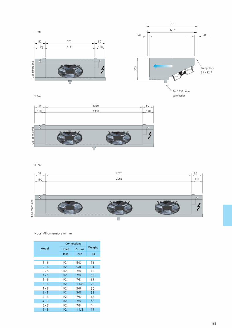
160 161
701
667
50 50
303
3/4“ BSP drain
connection
Fixing slots
25 x 12.7
675
715
50 50
Coi
l con
ns e
nd
130 130
1 Fan
1350
1390
50 50
Coi
l con
ns e
nd
130 130
2 Fan
2025
2065
50 50
Coi
l con
ns e
nd
130 130
3 Fan
Model
Inch
WeightInlet
Connections
Outlet
Inch kg
1 - 62 - 63 - 64 - 65 - 66 - 61 - 82 - 83 - 84 - 85 - 86 - 8
1/21/21/21/21/21/21/21/21/21/21/21/2
313448536673303347526572
5/85/87/87/87/81 1/85/85/87/87/87/81 1/8
Note: All dimensions in mm

162 163
GEA Searle - NS Air Coolers
NS Unit Cooler
This low profile range of NS unit coolers continues the GEA Searle philosophy of energy efficient product design. With a capacity range from 1.69 kW up to 6.93kW and 6mm fin spacing, these coolers are suitable for both high and low temperature applica-tions. The heat exchanger incorporates Searle’D’ fin with extended inner surface copper tube whichhas proved very popular since its introduction.
Its unique coil geometry is highly efficient and provides a high sec-ondary surface on which to deposit frost and extend initiation times between defrost cycles. The range is certified for its performance by Eurovent (see below) and the capacities listed are inaccordance with its strict rules.
Casework
All the coolers are constructed from aluminumsheet panels to form a rigid but lightweight structure. To enable the unit to be lifted directly into place the drain tray is constructed from pregalvanized steel. There are key hole slots in the top plate to allow the cooler to be fitted flush to the ceiling thereby limiting the op-portunities for bacterial growth. The end covers are secured by only two screws, thus making removal quick and easy for installation and service needs.
.Coils
Standard (Cu/Al) coils are manufactured from copper tube (with extended inner surface)mechanically expanded into aluminum fins. The fin shave metric fin spacing of 6mm, this equates to approximately 4 fins per inch. All coils are tested to 35.8 bar using dry air down to -40˚C dew point.
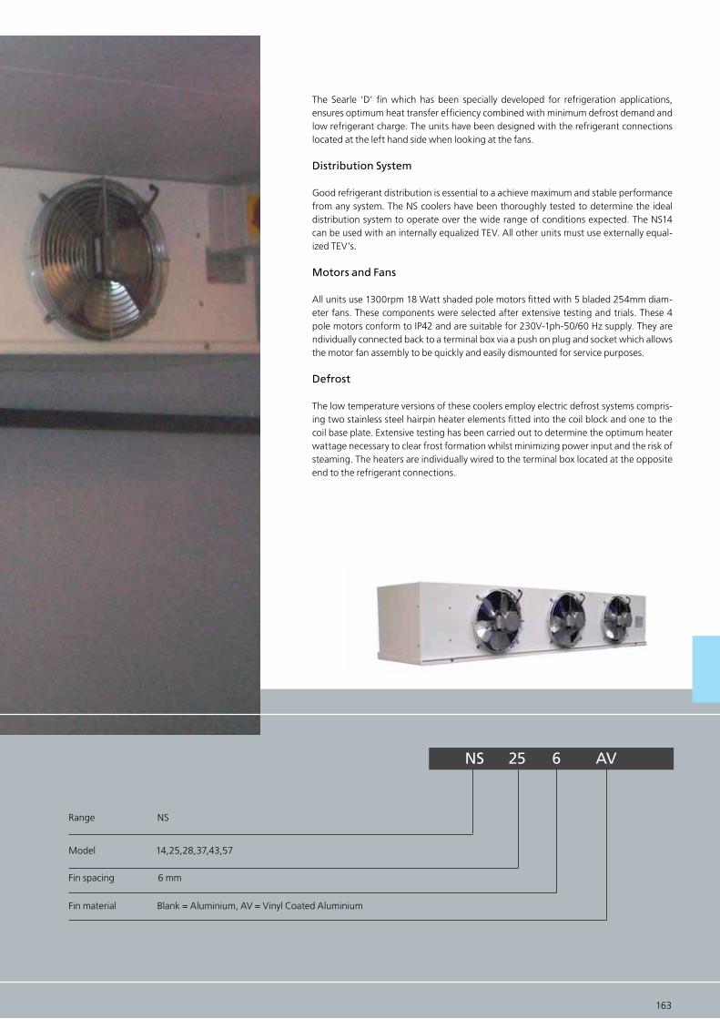
162 163
The Searle ‘D’ fin which has been specially developed for refrigeration applications, ensures optimum heat transfer efficiency combined with minimum defrost demand and low refrigerant charge. The units have been designed with the refrigerant connections located at the left hand side when looking at the fans.
Distribution System
Good refrigerant distribution is essential to a achieve maximum and stable performance from any system. The NS coolers have been thoroughly tested to determine the ideal distribution system to operate over the wide range of conditions expected. The NS14 can be used with an internally equalized TEV. All other units must use externally equal-ized TEV’s.
Motors and Fans
All units use 1300rpm 18 Watt shaded pole motors fitted with 5 bladed 254mm diam-eter fans. These components were selected after extensive testing and trials. These 4 pole motors conform to IP42 and are suitable for 230V-1ph-50/60 Hz supply. They are ndividually connected back to a terminal box via a push on plug and socket which allows the motor fan assembly to be quickly and easily dismounted for service purposes.
Defrost
The low temperature versions of these coolers employ electric defrost systems compris-ing two stainless steel hairpin heater elements fitted into the coil block and one to the coil base plate. Extensive testing has been carried out to determine the optimum heater wattage necessary to clear frost formation whilst minimizing power input and the risk of steaming. The heaters are individually wired to the terminal box located at the opposite end to the refrigerant connections.
NS 25 6 AV
Range NS
Model 14,25,28,37,43,57
Fin spacing 6 mm
Fin material Blank = Aluminium, AV = Vinyl Coated Aluminium
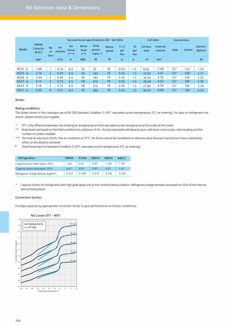
164 165
NS Selection data & Dimensions
Notes:
Rating conditions:The duties shown in this catalogue are at EN 328 Standard Condition 2 (-8°C saturated suction temperature, 0°C air entering). For data on refrigerants not shown, please contact your supplier.
* DT1 is the difference between the entering air temperature and the saturated suction temperature at the outlet of the cooler.** Noise levels are based on free field conditions at a distance of 3m. Actual noise levels will depend upon cold store construction, store loading and the number of coolers installed.*** Terminal air velocity 0.25m/s, free air conditions at 10°C. Air throw cannot be considered on absolute value because many factors have a substantial effect on the distance achieved. Total Power Input at Standard Condition 2 (-8°C saturated suction temperature, 0°C air entering).
* Capacity factors for refrigerants with high glide apply only at the nominal rating condition. Refrigerant charge densities are based on 25% of the internal volume being liquid.
NS14 - 6NS25 - 6NS28 - 6NS37 - 6NS43 - 6NS57 - 6
1.692.743.444.135.186.93
0.240.500.490.750.730.97
6.06.56.06.56.06.0
181818181818
1.51.51.51.51.51.5
1/2“1/2“1/2“1/2“1/2“1/2“
2.483.014.524.526.568.60
1/2“5/8“5/8“7/8“7/8“7/8“
Model
R404ACatacity
@ SC2
Air volume
Noise level(**)
Total power input
InletSurface
areaElectricdefrost
Noof
fans
9.0212.0218.0418.0427.0636.07
1.292.212.253.183.244.23
Internalvolume
WdBA m2
Refrigeration R404A R134a R507A R407CR407A
Capacity factor (dew point, DT1)
Capacity factor (mid point, DT1)
Refrigerant charge density (kg/dm3)
1.00
0.97
0.312
0.91
0.91
0.338
0.97
0.97
0.313
1.18*
0.91
0.332
1.35*
1.01
0.332
R404A/507AR134a
Correction factors
(multipy capacity by appropriate correction factor to give performance at chosen conditions)
NS Cooler DT1 - WET
kW*
535656585859
A
70140140210210280
OutletMotorspeed
0.550.550.550.550.550.55
F.L.C perfan
AW dm2
122334
m3/s
Fan and motor specifications 230 - 1ph 50Hz
Air throw(***)
m W
SC perfan
Coil data Connections
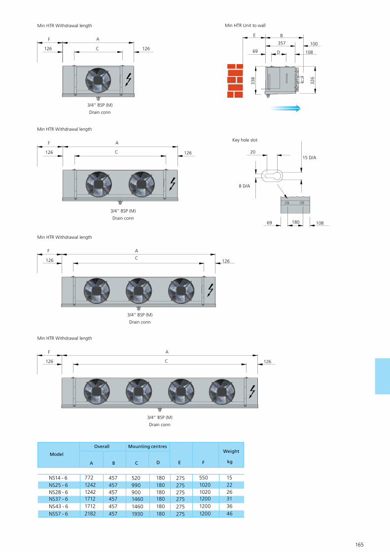
164 165
Model
A
Mounting centresOverall
B C
NS14 - 6NS25 - 6NS28 - 6NS37 - 6NS43 - 6NS57 - 6
152226313646
457457457457457457
520990900146014601930
55010201020120012001200
180180180180180180
275275275275275275
77212421242171217122182
Weight
kgD E F
F A
126126 C
3/4” BSP (M)
Drain conn
Min HTR Withdrawal length
Min HTR Withdrawal length
F A
126126 C
3/4” BSP (M)
Drain conn
Min HTR Withdrawal length
F A
126126 C
3/4” BSP (M)
Drain conn
Min HTR Withdrawal length
F A
126126 C
3/4” BSP (M)
Drain conn
E B
100
69
357
D
338
326
108
Min HTR Unit to wall
Key hole slot
20
180
15 D/A
69 108
8 D/A
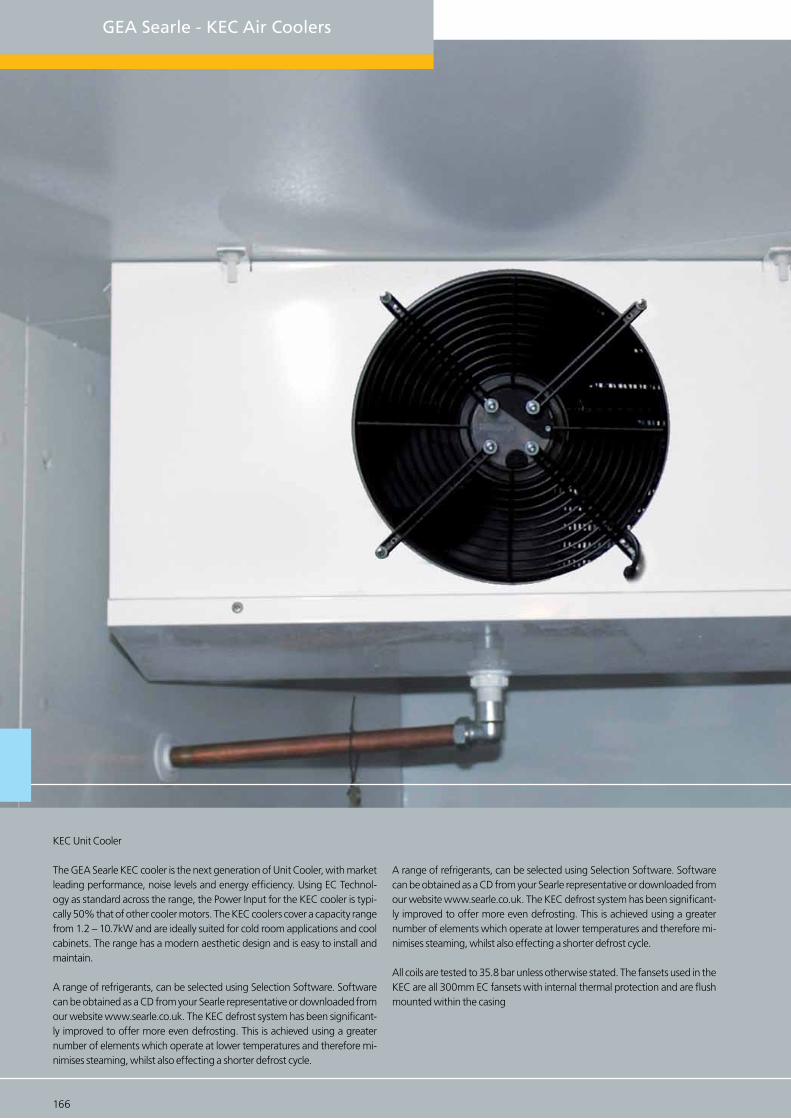
166 167
GEA Searle - KEC Air Coolers
KEC Unit Cooler
The GEA Searle KEC cooler is the next generation of Unit Cooler, with market leading performance, noise levels and energy efficiency. Using EC Technol-ogy as standard across the range, the Power Input for the KEC cooler is typi-cally 50% that of other cooler motors. The KEC coolers cover a capacity range from 1.2 – 10.7kW and are ideally suited for cold room applications and cool cabinets. The range has a modern aesthetic design and is easy to install and maintain.
A range of refrigerants, can be selected using Selection Software. Software can be obtained as a CD from your Searle representative or downloaded from our website www.searle.co.uk. The KEC defrost system has been significant-ly improved to offer more even defrosting. This is achieved using a greater number of elements which operate at lower temperatures and therefore mi-nimises steaming, whilst also effecting a shorter defrost cycle.
A range of refrigerants, can be selected using Selection Software. Software can be obtained as a CD from your Searle representative or downloaded from our website www.searle.co.uk. The KEC defrost system has been significant-ly improved to offer more even defrosting. This is achieved using a greater number of elements which operate at lower temperatures and therefore mi-nimises steaming, whilst also effecting a shorter defrost cycle.
All coils are tested to 35.8 bar unless otherwise stated. The fansets used in the KEC are all 300mm EC fansets with internal thermal protection and are flush mounted within the casing
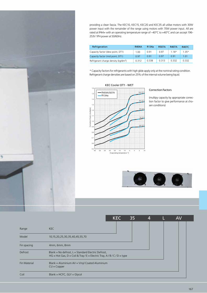
providing a clean fascia. The KEC10, KEC15, KEC20 and KEC35 all utilise motors with 30W power input with the remainder of the range using motors with 70W power input. All are rated at IP44+ with an operating temperature range of –40°C to +40°C and can accept 196-253V 1PH power at 50/60Hz.
* Capacity factors for refrigerants with high glide apply only at the nominal rating condition.Refrigerant charge densities are based on 25% of the internal volume being liquid.
166 167
R404A/507AR134a
KEC Cooler DT1 - WET
Correction Factors
(multipy capacity by appropriate correc-tion factor to give performance at cho-sen conditions)
Refrigeration R404A R134a R507A R407CR407A
Capacity factor (dew point, DT1)
Capacity factor (mid point, DT1)
Refrigerant charge density (kg/dm3)
1.00
0.97
0.312
0.91
0.91
0.338
0.97
0.97
0.313
1.18*
0.91
0.332
1.35*
1.01
0.332
KEC 35 4 L AV
Range KEC
Model 10,15,20,25,30,35,40,45,55,70
Coil Blank = HCFC, GLY = Glycol
Fin spacing 4mm, 6mm, 8mm
Defrost Blank = No defrost, L = Standard Electric Defrost, HG = Hot Gas, D = Coil & Tray / E = Electric Tray, A / B / C / D = type
Fin Material Blank = Aluminium AV = Vinyl Coated Aluminium CU = Copper

168 169
KEC Selection data & Dimensions
Notes:Rating conditions:The duties shown in this catalogue are at EN 328 Standard Condition 2 (-8°C saturated suction temperature, 0°C air entering). For data on refrigerants not shown, please contact your supplier.
* DT1 is the difference between the entering air temperature and the saturated suction temperature at the outlet of the cooler.** Noise levels are based on free field conditions at a distance of 3m. Actual noise levels will depend upon cold store construction, store loading and the number of coolers installed.*** Terminal air velocity 0.25m/s, free air conditions at 10°C. Air throw cannot be considered on absolute value because many factors have a substantial effect on the distance achieved. Total Power Input at Standard Condition 2 (-8°C saturated suction temperature, 0°C air entering).
ModelR507A R407C
Airvolume
Dry weightR404A
Connections
Inletkg
Totalsurface
area
Internalvolume
dm3 Outlet
Capacity kW 8K DT1 (SC2)*
R134a
m2
Ref charge
Coil data
1.601.952.282.913.624.435.676.788.5310.191.301.671.932.313.073.744.495.79
6.798.711.131.471.691.992.673.203.865.155.837.73
1.501.832.142.733.394.165.316.368.009.561.221.571.812.172.883.504.215.43
6.378.171.061.381.581.872.503.003.624.835.477.25
8.510.013.713.720.524.924.937.437.456.05.86.89.49.414.117.017.025.6
25.638.34.45.27.27.210.813.113.119.719.729.5
0.450.610.840.841.231.411.412.082.023.000.450.610.840.841.231.411.412.08
2.023.000.450.610.840.841.231.411.412.082.023.00
1/2“1/2“1/2“1/2“1/2“1/2“1/2“1/2“1/2“1/2“1/2“1/2“1/2“1/2“1/2“1/2“1/2“1/2“
1/2“1/2“1/2“1/2“1/2“1/2“1/2“1/2“1/2“1/2“1/2“1/2“
1/2“1/2“5/8“5/8“7/8“7/8“7/8“7/8“7/8“7/8“1/2“1/2“5/8“5/8“7/8“7/8“7/8“7/8“
7/8“7/8“1/2“1/2“5/8“5/8“7/8“7/8“7/8“7/8“7/8“7/8“
272833333547475367742728333335474753
677427283333354747536774
1.962.392.803.574.445.446.958.3210.4612.511.592.052.372.833.764.585.517.10
8.1010.691.391.812.072.453.273.934.746.327.159.48
0.280.280.290.420.400.580.830.811.251.210.310.310.320.430.420.630.850.83
1.281.250.320.320.330.440.430.650.860.861.311.29
1.41.92.62.63.84.44.46.46.39.31.41.92.52.63.84.34.46.4
6.39.31.41.92.52.53.84.34.36.46.39.3
1.652.012.353.003.734.575.846.998.7910.511.341.721.992.383.163.854.635.97
7.008.981.171.521.742.062.753.303.985.316.017.97
KEC10-4KEC15-4KEC20-4KEC25-4KEC30-4KEC35-4KEC40-4KEC45-4KEC55-4KEC70-4KEC10-6KEC15-6KEC20-6KEC25-6KEC30-6KEC35-6KEC40-6KEC45-6KEC55-6KEC70-6
KEC10-8KEC15-8KEC20-8KEC25-8KEC30-8KEC35-8KEC40-8KEC45-8KEC55-8KEC70-8
kg
4mm
6mm
8mm
Model Speed
m
Airthrow
***
StandardNo of fans Coil Pan
A
Totalpower +
F.L.C Ampsper fan
A
Fan and Motor specification
rpm dB(A)
SC Amps per fan
Electric defrost
Total
KEC10KEC15KEC20KEC25KEC30KEC35KEC40KEC45KEC55KEC70
1111122233
1370137013701750175013701750175017501750
16161622221622222222
Noiselevel**
W
230V - 1ph-50/60Hz 230V-1ph-50/60Hz
WWW
44444452524755555757
333333777766154154231231
0.350.350.350.700.700.350.700.700.700.70
0.50.50.51.01.00.51.01.01.01.0
68068092092092016001600160024002400
34034046046046080080080012001200
1020102013801380138024002400240036003600
m2/s

KEC35 - 45
Heater removal600mm (either end)
1326 O/A length1300 Casework
133 133
1“D/Conn377.5 377.5
48
1305 Drain pan
168 169
KEC 10 - 15
Heater removal500mm (either end)
726 O/A length
700 Casework
133 133
1“D/Conn
352.5 352.5
48
705 Drain pan
KEC 20 - 30
Heater removal600mm (either end)
876 O/A length
850 Casework
133 133
1“D/Conn
427.5 427.5
48
855 Drain pan
442 Casework 275 min
393
412
461
O/A
Hei
gth
460 Drain pan
25
30
1517.5
46
Hanging braket
Co
il co
nn
s en
d
653 653
550
Heater removal600mm (either end)
KEC55 - 701826 O/A length
1800 Casework
133 133
1“D/Conn48
1805 Drain pan
427.5 427.5475 475
Note
Maintenance access require both ends of unit
All dimensions in mm

170 171
GEA Searle - KMe Air Coolers
KMe Unit Cooler
The KMe range of coolers is ideally suited to largecold rooms and small ware-houses where an efficient solution is required. The KMe can also be used for industrial food processing and agricultural applications.
To find the optimum model from the range it is recommened to use the Sear-le Selection Software. The KMe utilises the unique GEA Searle ‘D’ fin which has been specifically developed for refrigeration applications. The ‘D’ fin uti-lises ½” outside diameter tube with extended inner surface – ‘rifle bore’ – to maximise performance. It balances the requirements of high efficiency heat transfer with the need to have secondary surface on which to deposit frost and maximise the periods between defrosts. All coils are tested to 35.8 bar and have a maximum operating pressure of 20.7 bar unless otherwise stated.
KMe Options
EC Fansets
Air streamer – to extend the air throw of the standard 400mm fanset
Forkguard – a guard system to prevent accidental damage from forklift trucks or similar when siting the cooler at low level.
Axial fans – for significantly increased air throw or for external pressure of 120Pa.
Peripheral Heaters – available in conjunction with axial fans, recommended for applications below 0°C.

170 171
Fan plate Heaters
Heavy Electric Defrost – comprises of additional coil block heaters to increase the total de-frost load by approximately 40%
Fan Plate Heaters – to prevent fan blade contact with frost build up at low tempera-tures.
R404A/507AR134a
KMe Cooler DT1 - WET
Refrigeration R404A R134a R507A R407CR407A
Capacity factor (dew point, DT1)
Capacity factor (mid point, DT1)
Refrigerant charge density (kg/dm3)
1.00
0.97
0.312
0.91
0.91
0.338
0.97
0.97
0.313
1.18*
0.91
0.332
1.35*
1.01
0.332
* Capacity factors for refrigerants with high glide apply only at the nominal rating condi-tion. Refrigerant charge densities are based on 25% of the internal volume being liquid.
Correction Factors
(multipy capacity by appropriate cor-rection factor to give performance at chosen conditions.
KMe 140 - 6 L - AV - 3PH - EC
Range KEC
Model 50, 60, 80, 95, 115, 140, 175
Electrical Supply Blank = 1PH, 3PH = 3PH
Fin spacing 4mm, 6mm, 8mm
Defrost Blank = No Defrost, L = Standard Electric , L2 = Heavy Duty Electric HG = Hot Gas, D = Coil & Tray / E = Electric Tray, A / B / C / D = type
Fin Material Blank = Aluminium AV = Vinyl coated Aluminium CU = Copper
Fanset Options Blank = Standard 400mm fanset , Ax = Axial, EC = EC Fanset

172 173
KMe Selection data & Dimensions
ModelR507A R407C
Airvolume
Dry weightR404A
Connections
Inletkg
Totalsurface
area
Internalvolume
dm3 Outlet
Capacity kW 8K DT1 (SC2)*
R134a
m2
Ref charge
Coil data
7.148.4411.8414.3417.8621.6227.086.017.239.4512.1314.1818.1423.145.536.618.3211.12
12.5516.6721.25
6.707.9211.1113.4516.7520.2825.415.646.788.8611.3813.3017.0221.715.196.207.8110.43
11.7815.6419.94
37.856.050.475.675.6113.4134.425.938.334.551.851.877.792.119.929.526.539.8
39.859.770.8
2.12.92.63.93.85.66.62.12.92.63.93.85.66.62.12.92.63.9
3.85.66.6
1/2“5/8“5/8“5/8“7/8“7/8“7/8“1/2“5/8“5/8“5/8“7/8“7/8“7/8“1/2“5/8“5/8“5/8“
7/8“7/8“7/8“
1 1/8“1 1/8“1 1/8“1 1/8“1 3/8“1 3/8“1 3/8“1 1/8“1 1/8“1 1/8“1 1/8“1 3/8“1 3/8“1 3/8“1 1/8“1 1/8“1 1/8“1 1/8“
1 3/8“1 3/8“1 3/8“
851121291391701952178310912613516619021284110127136
167191212
8.7610.3514.5317.5921.9126.5333.227.388.8711.5914.8817.4022.2528.397.709.1911.5815.47
17.4723.2129.58
0.890.961.891.782.832.683.450.981.012.001.953.002.933.861.021.032.052.04
3.073.064.06
6.79.58.412.512.218.421.66.79.58.412.512.218.421.66.79.58.412.5
12.218.421.6
7.368.7012.2114.7818.4122.2927.926.207.459.7412.5014.6218.7023.865.706.818.5811.46
12.9417.1921.91
KMe50-4KMe60-4KMe80-4KMe95-4KMe115-4KMe140-4KMe175-4KMe50-6KMe60-6KMe80-6KMe95-6KMe115-6KMe140-6KMe175-6KMe50-8KMe60-8KMe80-8KMe95-8KMe115-8KMe140-8
KMe175-8
kg
4mm
6mm
8mm
m2/s
Notes:Rating conditions:The duties shown in this catalogue are at EN 328 Standard Condition 2 (-8°C saturated suction temperature, 0°C air entering). For data on refrigerants not shown, please contact your supplier.
* DT1 is the difference between the entering air temperature and the saturated suction temperature at the outlet of the cooler.** Noise levels are based on free field conditions at a distance of 3m. Actual noise levels will depend upon cold store construction, store loading and the number of coolers installed.*** Terminal air velocity 0.25m/s, free air conditions at 10°C. Air throw cannot be considered on absolute value because many factors have a substantial effect on the distance achieved. Total Power Input at Standard Condition 2 (-8°C saturated suction temperature, 0°C air entering).
Model Speed
4mmm
Air throw std/thrower
***
StandardNo of fans
Coil Pan
A
Totalpower
+
F.L.C Amps
per fan
A
Fan and Motor specification
rpm dB(A)
SC Amps
per fan
Electric defrost
Total
1111122
1410141014101410141014101410
17/2619/2919/2917/2619/2917/2617/26
Noiselevel**
W
230V - 1ph-50Hz 40V - 3ph
WWW
60606363656566
1.051.051.051.051.051.051.05
795120015901590240024002820
2385360048304830720072008460
2650400054005400800080009400
795120015901590240024002820
KMe50KMe60KMe80KMe95KMe115KMe140KMe175
400400400400400400400
Diameter
mm
19/2922/3422/3419/2922/3419/2919/29
8mmm
200200400400600600800
3.33.33.33.33.33.33.3
0.650.650.650.650.650.650.65
200200400400600600800
Totalpower
+
A
F.L.C Amps
per fan
A
SC Amps
per fan
W
2.62.62.62.62.62.62.6
1590240032403240480048005640
Heavy duty
Total
W
Coil
W
400V - 3ph-50Hz
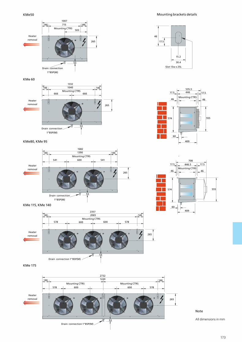
172 173
KMe50
1007
715
Mounting CTRS503
146 146
53
265
Heater
removal
Drain connection
1“BSP(M)
KMe 60
KMe80, KMe 95
KMe 115, KMe 140
KMe 175
Heater
removal
53Drain connection
1“BSP(M)
13321040
Mounting CTRS666
146 146
265
666
Heater
removal
53Drain connection
1“BSP(M)
16821390
Mounting CTRS
541
146 146
265
541 600
Heater
removal
53
Drain connection 1“BSP(M)
23572065
Mounting CTRS600
146 146
265
578 600
Heater
removal
53
27321220
Mounting CTRS
600
146 146
265
578 600
Drain connection 1“BSP(M)
578
578
Mounting CTRS
Mounting brackets details
30.4
46
15.2
Slot 13w x 25L
17.5
44617.5
46
535.5
46
17.5
555574
60
409
Mounting CTRS
Mounting CTRS
17.5
46
708
46
17.5
555574
60
409
446.5
Note
All dimensions in mm
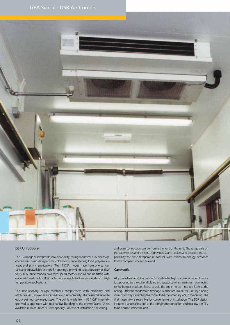
GEA Searle - DSR Air Coolers
DSR Unit Cooler
The DSR range of low profile, low air velocity, ceiling mounted, dual discharge coolers has been designed for cold rooms, laboratories, food preparation areas and similar applications. The 11 DSR models have from one to four fans and are available in three fin spacings, providing capacities from 0.8kW to 15.1kW. Nine models have two speed motors and all can be fitted with optional speed control.DSR coolers are available for low temperature or high temperature applications.
The revolutionary design combines compactness with efficiency and attractiveness, as well as accessibility and serviceability. The casework is white epoxy painted galvanised steel. The coil is made from 1/2” O/D internally grooved copper tube with mechanical bonding to the proven Searle ‘D’ fin available in 3mm, 4mm or 6mm spacing. For ease of installation, the wiring
and drain connection can be from either end of the unit. The range calls on the experiences and designs of previous Searle coolers and provides the op-portunity for close temperature control, with minimum energy demands from a compact, unobtrusive unit.
Casework
All external metalwork is finished in a white high gloss epoxy powder. The coil is supported by the coil end plates and supports which are in turn connected to the hanger brackets. These enable the cooler to be mounted flush to the ceiling. Efficient condensate drainage is achieved inside the unit by sloping inner drain trays, enabling the cooler to be mounted square to the ceiling. The drain assembly is reversible for convenience of installation. The DSR design includes a space allocation at the refrigerant connection end to allow the TEV to be housed inside the unit.
174 175

Corrosion Protection
The rigid case structure is fabricated from galvanised sheet steel. Paint is applied to external surfaces in GEA Searle’s modern electrostatic powder paint plant then baked and cured at 180°C, ensuring an even, flexible and durable finish.
Coils
The coil block comprises 1/2” diameter copper tubes with an extended inner surface ensuring maximum heat transfer efficiency and minimum refrigerant charge. The tubes are mechanical-ly expanded to form a tight interference fit into the collars of the aluminium fins. This efficient design reduces the cooler’s physical size thus maximising storage capacity. Standard coils are tested to 35.8 bar before they leave the factory.
Coil Options:
Cu/AL - Copper tubes with Aluminium fins, Cu/AV - Copper tubes with vinyl-coated, Alumini-um fins (3mm and 4mm fin spacing), Coils circuited for glycol.
Specification
Motors and Fans
All DSR units utilise internally protected single phase squirrel cage motors of a totally enclosed, air cooled, permanent capacitor type in an IP44 enclosure. They are individu-ally wired via plug and socket connectors and cable trays back to a robust junction box, where an electrical bridging facility is provided. High or low speed operation (excluding DSR 100 & 116) is obtained by connecting the electrical supply to the appropriate ter-minals. The motors on the DSR 100 & 116 are suitable for speed control via an optional Searle Triac controller
Models DSR 12 to DSR 83 use a 305mm propellertype five-bladed fan with a fractional dual speed 25W motor. A pitch of 24° is supplied for 50Hz applications and 20° for 60Hz. Models DSR 100 and DSR 116 are fitted with four-bladed 305mm fans and 70W single speed motors, running at 4-pole speed. A pitch of 32° is supplied for 50Hz ap-plications and 26° for 60Hz.
Speed Control on DSR 100 & DSR 116 Speed control on DSR models 100 & 116 can be utilised to tailor air velocities to suit various applications - e.g to minimise possible pe sonnel discomfort caused by airflow or noise. To achieve lower speeds on the single speed 70 Watt motors found on DSR100 and 116 models, Searle offers a manually oper-ated, Triac type speed controller which must be ordered separately. Performances for atypical speed of 800rpm are given in the Selection data.
For other speeds, air flow and thermal performance are approximately proportional to speed. Operation at any speed between 600 rpm and maximum is approved.
DSR 42 -4 L
Range DSR
Model 12,19,22,36,42,51,62,68,83,100,116
Frequency Blank = 50Hz, 60 = 60Hz
Fin spacing 3mm, 4mm, 6mm
Defrost Blank = No defrost, L = Standard Electric Defrost
Fin Material Blank = Aluminium AV = Vinyl Coated Aluminium
174 175
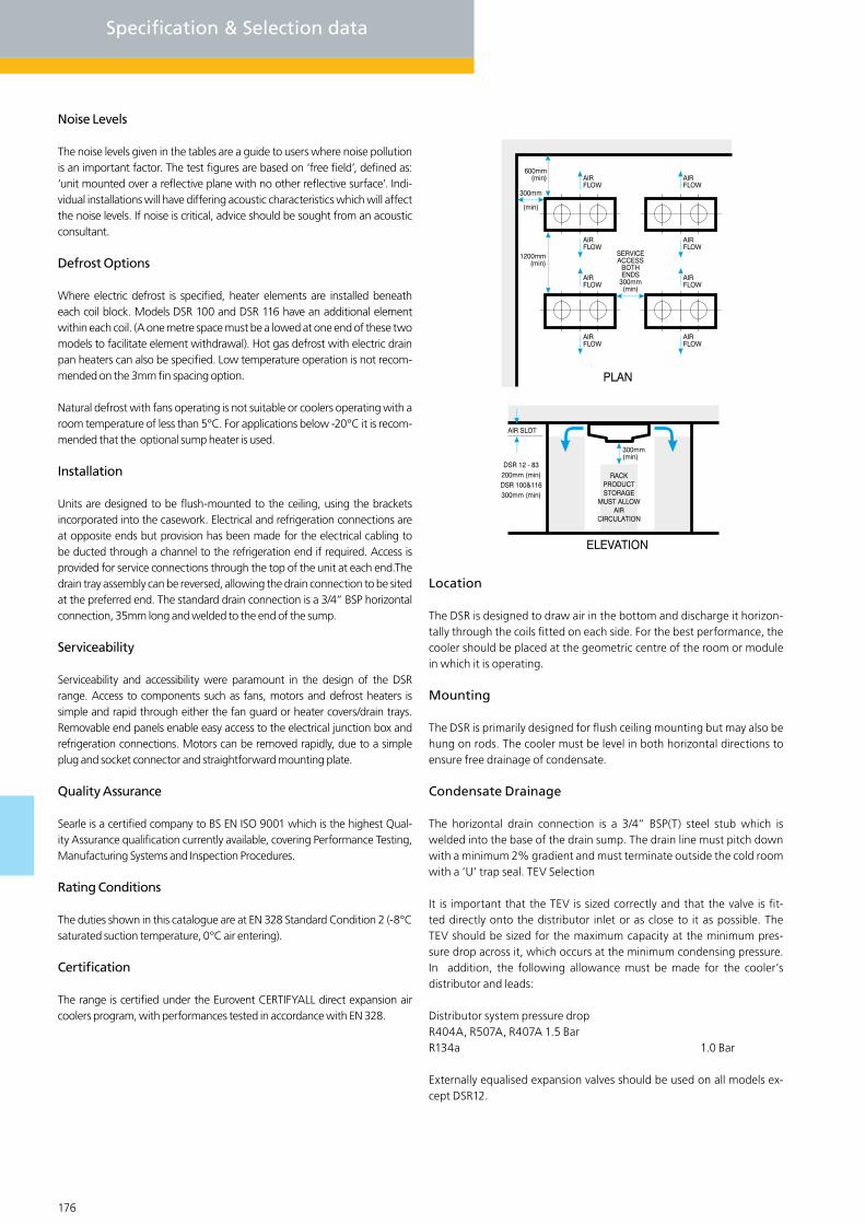
176 177
Noise Levels
The noise levels given in the tables are a guide to users where noise pollution is an important factor. The test figures are based on ‘free field’, defined as: ‘unit mounted over a reflective plane with no other reflective surface’. Indi-vidual installations will have differing acoustic characteristics which will affect the noise levels. If noise is critical, advice should be sought from an acoustic consultant.
Defrost Options
Where electric defrost is specified, heater elements are installed beneath each coil block. Models DSR 100 and DSR 116 have an additional element within each coil. (A one metre space must be a lowed at one end of these two models to facilitate element withdrawal). Hot gas defrost with electric drain pan heaters can also be specified. Low temperature operation is not recom-mended on the 3mm fin spacing option.
Natural defrost with fans operating is not suitable or coolers operating with a room temperature of less than 5°C. For applications below -20°C it is recom-mended that the optional sump heater is used.
Installation
Units are designed to be flush-mounted to the ceiling, using the brackets incorporated into the casework. Electrical and refrigeration connections are at opposite ends but provision has been made for the electrical cabling to be ducted through a channel to the refrigeration end if required. Access is provided for service connections through the top of the unit at each end.The drain tray assembly can be reversed, allowing the drain connection to be sited at the preferred end. The standard drain connection is a 3/4” BSP horizontal connection, 35mm long and welded to the end of the sump.
Serviceability
Serviceability and accessibility were paramount in the design of the DSR range. Access to components such as fans, motors and defrost heaters is simple and rapid through either the fan guard or heater covers/drain trays. Removable end panels enable easy access to the electrical junction box and refrigeration connections. Motors can be removed rapidly, due to a simple plug and socket connector and straightforward mounting plate.
Quality Assurance
Searle is a certified company to BS EN ISO 9001 which is the highest Qual-ity Assurance qualification currently available, covering Performance Testing, Manufacturing Systems and Inspection Procedures.
Rating Conditions
The duties shown in this catalogue are at EN 328 Standard Condition 2 (-8°C saturated suction temperature, 0°C air entering).
Certification
The range is certified under the Eurovent CERTIFYALL direct expansion air coolers program, with performances tested in accordance with EN 328.
Location
The DSR is designed to draw air in the bottom and discharge it horizon-tally through the coils fitted on each side. For the best performance, the cooler should be placed at the geometric centre of the room or module in which it is operating.
Mounting
The DSR is primarily designed for flush ceiling mounting but may also be hung on rods. The cooler must be level in both horizontal directions to ensure free drainage of condensate.
Condensate Drainage
The horizontal drain connection is a 3/4” BSP(T) steel stub which is welded into the base of the drain sump. The drain line must pitch down with a minimum 2% gradient and must terminate outside the cold room with a ‘U’ trap seal. TEV Selection
It is important that the TEV is sized correctly and that the valve is fit-ted directly onto the distributor inlet or as close to it as possible. The TEV should be sized for the maximum capacity at the minimum pres-sure drop across it, which occurs at the minimum condensing pressure. In addition, the following allowance must be made for the cooler’s distributor and leads:
Distributor system pressure dropR404A, R507A, R407A 1.5 BarR134a 1.0 Bar
Externally equalised expansion valves should be used on all models ex-cept DSR12.
Specification & Selection data
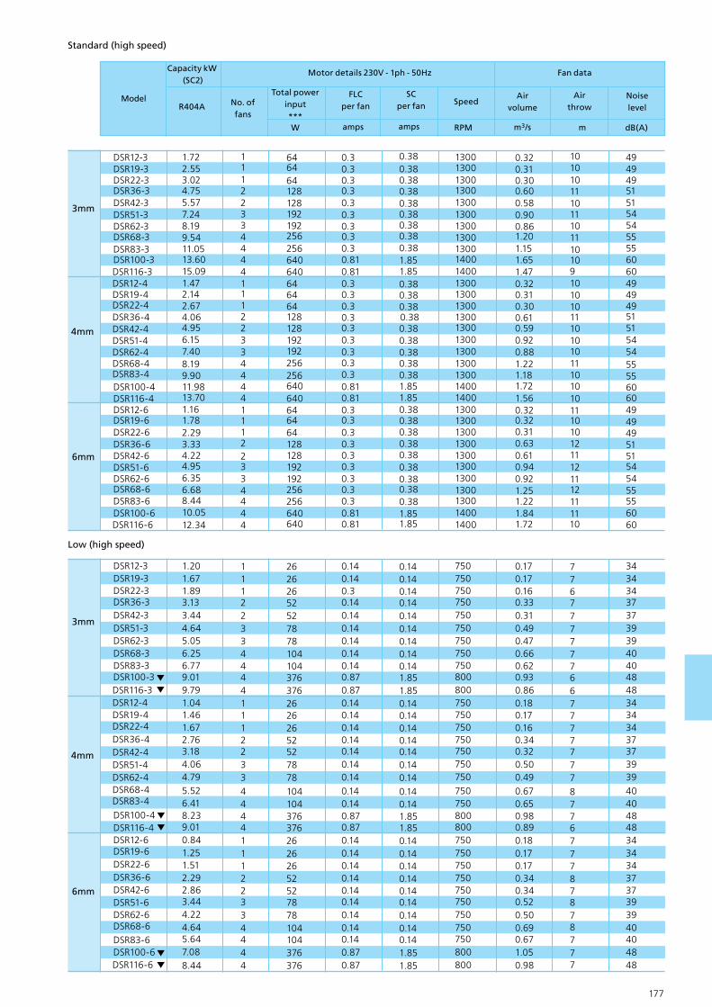
176 177
3mm
4mm
6mm
111223344441112233444411122334444
646464128128192192256256640640646464128128192192256256640640646464128128192192256256640640
130013001300130013001300130013001300140014001300130013001300130013001300130013001400140013001300130013001300130013001300130014001400
10101011101110111010910101011101010111010101110101211121112111110
494949515154545555606049494951515454555560604949495151545455556060
0.30.30.30.30.30.30.30.30.30.810.810.30.30.30.30.30.30.30.30.30.810.810.30.30.30.30.30.30.30.30.30.810.81
0.380.380.380.380.380.380.380.380.381.851.850.380.380.380.380.380.380.380.380.381.851.850.380.380.380.380.380.380.380.380.381.851.85
0.320.310.300.600.580.900.861.201.151.651.470.320.310.300.610.590.920.881.221.181.721.560.320.320.310.630.610.940.921.251.221.841.72
DSR12-3DSR19-3DSR22-3DSR36-3DSR42-3DSR51-3DSR62-3DSR68-3DSR83-3DSR100-3DSR116-3DSR12-4DSR19-4DSR22-4DSR36-4DSR42-4DSR51-4DSR62-4DSR68-4DSR83-4DSR100-4DSR116-4DSR12-6DSR19-6DSR22-6DSR36-6DSR42-6DSR51-6DSR62-6DSR68-6DSR83-6DSR100-6DSR116-6
1.722.553.024.755.577.248.199.5411.0513.6015.091.472.142.674.064.956.157.408.199.9011.9813.701.161.782.293.334.224.956.356.688.4410.0512.34
3mm
4mm
6mm
111223344441112233444411122334444
262626525278781041043763762626265252787810410437637626262652527878104104376376
750750750750750750750750750800800750750750750750750750750750800800750750750750750750750750750800800
776777777667777777877677787878777
343434373739394040484834343437373939404048483434343737393940404848
0.140.140.30.140.140.140.140.140.140.870.870.140.140.140.140.140.140.140.140.140.870.870.140.140.140.140.140.140.140.140.140.870.87
0.140.140.140.140.140.140.140.140.141.851.850.140.140.140.140.140.140.140.140.141.851.850.140.140.140.140.140.140.140.140.141.851.85
0.170.170.160.330.310.490.470.660.620.930.860.180.170.160.340.320.500.490.670.650.980.890.180.170.170.340.340.520.500.690.671.050.98
DSR12-3DSR19-3DSR22-3DSR36-3DSR42-3DSR51-3DSR62-3DSR68-3DSR83-3DSR100-3DSR116-3DSR12-4DSR19-4DSR22-4DSR36-4DSR42-4DSR51-4DSR62-4DSR68-4DSR83-4DSR100-4DSR116-4DSR12-6DSR19-6DSR22-6DSR36-6DSR42-6DSR51-6DSR62-6DSR68-6DSR83-6DSR100-6DSR116-6
1.201.671.893.133.444.645.056.256.779.019.791.041.461.672.763.184.064.795.526.418.239.010.841.251.512.292.863.444.224.645.647.088.44
ModelTotal power
input ***
FLCper fan
NoiselevelR404A
Airthrow
m3/s
SCper fan Speed
RPM m
Capacity kW (SC2)
No. of fans
amps
Air volume
Motor details 230V - 1ph - 50Hz
dB(A)ampsW
Fan data
Standard (high speed)
Low (high speed)

178 179
Selection data & Dimensions
6.8514.0
21.0
25.037.037.056.050.075.0
75.0112.0
4.709.40
14.017.026.026.038.034.0
51.051.077.0
1/2“1/2“
1/2“1/2“1/2“1/2“1/2“1/2“1/2“5/8“5/8“
1.581.58
1.58
2.852.854.274.275.705.707.677.67
1.252.503.754.226.346.149.228.0712.1012.1018.14
0.360.721.071.211.821.762.642.313.47
3.475.20
1/2“5/8“5/8“7/8“7/8“7/8“1 1/8“1 1/8“
1 1/8“1 3/8“1 3/8“
DSR12DSR19DSR22DSR36DSR42DSR51DSR62DSR68DSR83DSR100DSR116
9.0018.0027.0033.049.049.074.066.098.098.0148.0
Model Total surface area m2
Defrost230V
(4/6mm only)
kg
Imternalvolume
Approx. refcharge
dm3 Inlet4mm
Connections
Coil data
Outlet3mm kW6mm
R404A/507AR134a
KMe Cooler DT1 - WET
Refrigeration R404A R134a R507A R407CR407A
Capacity factor (dew point, DT1)
Capacity factor (mid point, DT1)
Refrigerant charge density (kg/dm3)
1.00
0.97
0.312
0.91
0.91
0.338
0.97
0.97
0.313
1.18*
0.91
0.332
1.35*
1.01
0.332
* Dew point capacity factors for refrigeration with high glide apply only at the nominal rating condi-tion. Mid point factors can be used for all conditions. Refrigerant Charge Densities based on 25% of the internal volume being liquid
Correction Factors
(multipy capacity by appropriate correction factor to give performance at chosen conditions.
Capacity
The duties presented in the specification tables are nominal capacities for operational (or “wet”) conditions. They have been calculated from the tested ‘dry‘ conditions, co duct-ed in accordance with EN 328, using ratios as specified by Eurovent Standard 7/C/001 which are shown. Tests are conducted under dry conditions wich allows performance to stabilise and permits measurements over a prolonged period. Please note that these ratios are already included in the performance data.
Standard
condition
Air temp./
Evap. temp
Relative
humidityRatio
SC1
SC2
SC3
SC4
10OC / OC
0OC / -8OC
-18OC / OC
-25OC / -31OC
85%
85%
95%
95%
1.35
1.15
1.05
1.00

178 179
266266266
266266266266266266
351351
580580
58010301030153015301015 x 2
1015 x 21015 x 21015 x 2
5357
618188107118136150161181
5256
58
7883102111130141152167
445445445445445445445445445530530
550550550100010001500150020002000
20002000
5256597985104113132
144155172
DSR12DSR19DSR22DSR36DSR42DSR51DSR62DSR68DSR83DSR100DSR116
87087087013201320182018202320232023202320
ModelLength
E
Depth+ tray
Fin length
D 3mmB
Weight (kg)
4mmA 6mmC
DepthFixing
centres
End view
Side view
16.5 916 Mounting centres10 x 25 mounting slot
910
50Liquid inlet outlet
16.5 C Mounting centers C Mounting centers
E Fin lengthE Fin length
A
B
Drain conn.3/4“ BSP
35
62
54
1“ BSP (M) drain connection
Centre support DSR 68, 83, 100 and 116 only

GEA Searle’s range of industrial cooling products, offer a wide range of solutions for industrial refrigeration, both standard and special. In addition, GEA Searle also offer unmatched technical sup-port and excellent manufacturing capabilities and capacity. Based on many years experience in these market places, GEA Searle can combine these resources to work with customers in designing and manufacturing bespoke solutions to meet any industrial applica-tion.
GEA Searle - Industrial Air Coolers
180 181

General range features
Motors & Fansets
GEA Searle selects the optimum combination of motors and fans to deliver the best performance for the cooler size and application range. All motors and fansets are verified for power input and air volume in our Research & Development department. Specific motor data details are provided in the relevant section for each cooler type.
Casework
The LSR , SM and FM coolers are manufactured using galvanised sheet case work, white or grey power coated, oven cured at 180 oc to provide a gard durable finish.
Blygold Coating (Optional)
GEA Searle has installed a purpose built coating facility to apply the Blygold coil protection coating to any size of coil. Blygold withstands almost all chemical vapour exposure conditions and is ideal for the following applica-tion areas :-
Corrosive environments Aggressive industrial areas
The duties presented in the specification tables are nominal capacities for operational (or ‘wet’) conditions. They have been calculated from the tested ‘dry’ conditions, conducted in accordance with EN 328, using ratios as specified by Eurovent Standard 7/C/001. Tests are conducted under dry conditions which allows performance to stabillise and permits measurement over a prolonged period. Please note that these ratios are already included in the performance data.
*Dew point capacity factors for refrigerants withb high glide apply only at the nominal rating condition. Mid point factors can be used for all condi-tions. Refrigerant Charge Densities based on 25% of the internal volume being liquid.
Refrigeration R404A R134a R507A R407CR407A
Capacity factor (dew point, DT1)
Capacity factor (mid point, DT1)
Refrigerant charge density (kg/dm3)
1.00
0.97
0.312
0.91
0.91
0.338
0.97
0.97
0.313
1.18*
0.91
0.332
135*
1.01
0.332
180 181

182 183
GEA Searle - LSR Industrial Coolers
General
The LSR range of dual discharge coolers has been developed to meet the de-mands of general cold storage along with those associated with food produc-tion and preparation halls. The range is divided into 3 main sections based upon fan speed.
Refrigerant and Coil
Capacity data is shown for R404A, with correction factors provided for other common refrigerants. For refrigerants and fluids not shown, including am-monia and water/glycol mixes, please consult your supplier. The ‘D’ fin when fitted with extended inner surface tubes delivers high performance with com-petitive pricing. Within the catalogue we offer 4 and 6mm fin pitch variants, for other fin spacing’s please consult your supplier.
LSR Industrial Cooler
Features
Versatile range of dual discharge coolers.
Ideallly suited to production/preparation stores.
Robust construction, designed to withstand demanding applications.
Easy access via hinged drainpan’s and fan plate(s) for maintenance and cleaning.
Fin design provides high surface area for frost build-up. Minimal refrigerant charge.

182 183
Fans / Motors and Noise levels
The 4 pole (nominal 1340rpm) high speed, high velocity and higher noise level units are sui able for all temperatures although it should be noted that when operating above 0°C there is a high likelihood of moisture carryover. The 6 pole (nominal 930rpm) mid speed, velocity and noise units are suitable for all temperatures and offer the best compromise between noise and performance. The 8 pole (nominal 680rpm) offers the lowest noise, lowest speed, air velocity and noise and is particularly suited to production/ preparation halls where operators work for prolonged periods.
Noise levels are quoted at a distance of 3m from the unit at an angle of 45° to the horizon-tal within a free field condition. The figures are supplied as a guide only, showing compara-tive noise levels between models and fan selections. If the application was noise sensitive we would advise the appointment of an independent noise consultant.
Air Throws and Pump Circulation
Air throws quoted within this catalogue are based on a terminal velocity of 0.25m/s in ideal conditions. Store layout, cooler location and discharge orientation can affect the air throw. Please refer to your supplier for further information. For Pump Circulation arranged as bottom feed for pump rates between 3:1 and 5:1. For other pump rates please refer to your supplier.
Defrost Options
Electric defrost coil and draintray Stainless steel heater elements with hermetically sealed terminals are pre-wired to a common junction box. Hot gas coil, electric draintray (HGEA, HGEB, HGEC, HGED) Incorporating four circuiting options all with electric heat-er rods within the draintray. Hot gas coil and draintray (HGDA, HGDB, HGDC, HGDD) Generally as above but units are supplied with a hot gas tube matrix within the draintray.
LSR 12 1 - 4 4D - 4 - EL CU/ALRange LSR
Height of case 12 tube high
Fan speed 4D, 6D, 8D
No. of fans 1, 2, 3, 4
Coil depth 4, 6No. of rows
Fin spacing 4mm, 6mm
R404A/507AR134a
LSR Cooler DT1 - WETOptions
Additional options available include double skinned and insulated drainpans, and isolator per fan.
Rating Conditions
The duties shown in this catalogue areat Eurovent Standard 7/C/001, Standard Condition 2 - (-8°C saturated suction temp. (dew point), 0°C air entering). Ca-pacities are based on DT1 the difference between the entering air temperature and the saturated suction temperature at the outlet of the cooler.
Coil materials Cu/Al = Copper, Aluminium fin, Cu/Av = Copper tube, vinyl coated Aluminium fin (4mm only) Cu/Cu = Copper tube, copper fin, Cu/ET = Copper tube, copper fin electro - tinned
Defrost El = Electric defrost in coil and drain tray, HGEA,B,C,D = hot gas coil, electric drain tray defrost, HGDA,B = hot gas coil and drain tray defrost, HGDC = hot gas coil and drain tray defrost, HGDD = hot gas coil and drain tray defrost,

184 185
4 pole high speed (low temperature, evaporating below -10oc)
LSR1
21-4
4-4
DLS
R121
-64
-4D
LSR1
22-4
4-4
DLS
R122
-64
-4D
LSR1
23-4
4-4
DLS
R123
-64
-4D
LSR1
24-4
4-4
DLS
R124
-64
-4D
LSR1
21-4
6-4
DLS
R121
-66
-4D
LSR1
22-4
6-4
DLS
R122
-66
-4D
LSR1
23-4
6-4
D
LSR1
23-6
6-4
DLS
R124
-46
-4D
LSR1
24-6
6-4
D
12.7
14.6
25.4
29.7
38.2
44.
5151
.059
.3
10.9
13.4
21.5
27.3
32.2
40.9
42.9
54.6
1 1 2 2 3 3 4 4 1 1 2 2 3 3 4 4
700
700
140
014
00
210
021
00
280
028
00
700
700
140
014
00
210
0
210
028
00
280
0
1.50
1.50
1.50
1.50
1.50
1.50
1.50
1.50
1.50
1.50
1.50
1.50
1.50
1.50
1.50
1.50
5.0
5.0
5.0
5.0
5.0
5.0
5.0
5.0
5.0
5.0
5.0
5.0
5.0
5.0
5.0
5.0
1340
1340
1340
1340
1340
1340
1340
1340
1340
1340
1340
1340
1340
1340
1340
1340
1.93
1.78
3.86
3.55
5.78
5.33
7.71
7.10
2.15
2.07
4.29
4.13
6.43
6.20
8.57
8.27
11 9 11 9 11 9 11 9 13 11 13 11 13 11 13 11
59 59 62 62 64
64
65 65 59 59 62 62 64
64
65 65
1/2“
1/2“
1/3“
5/8“
5/8“
5/8“
7/8“
7/8“
1/2“
1/2“
1/2“
5/8“
5/8“
5/8“
7/8“
7/8“
1 1/
8“1
1/8“
1 1/
8“1
1/8“
1 1/
8“1
1/8“
1 1/
8“1
1/8“
1 1/
8“1
1/8“
1 1/
8“1
1/8“
1 1/
8“
1 1/
8“1
1/8“
1 1/
8“
9.5
13.9
17.5
26.3
25.7
38.6
32.6
48.
8
9.5
13.9
17.5
26.3
25.7
38.6
32.6
48.
8
50 76 101
151
151
227
207
303
35 52 69 103
103
155
138
207
3.2
3.2
6.4
6.4
9.5
9.5
12.7
12.7
3.2
3.2
6.4
6.4
9.5
9.5
12.7
12.7
1.6
1.6
3.2
3.2
4.8
4.8
6.4
6.4
1.6
1.6
3.2
3.2
4.8
4.8
6.4
6.4
4mm 6mm
Fin
sp
acin
gM
od
el
Cap
acit
yR
404A
kWW
Am
ps
Am
ps
RPM
m3/s
md
B(A
)d
m3
m2
kWkW
No
. of
fan
s
Mo
tor
det
ails
40
0V -
3ph
- 50
Hz
FLC
per
fan
SCp
er f
anSp
eed
Tota
lp
ow
erin
pu
t
Air
volu
me
Air
thro
wN
ois
ele
vel
@3m
Fan
dat
a (5
00m
m d
imet
er)
Co
nn
ecti
on
s
Inle
t(2
off
)O
utl
et(2
off
)
Inte
rnal
volu
me
Surf
ace
area
Co
ilTr
ay
Def
rost
hea
ter
load
s at
20
0V
No
te: 4
pol
e co
oler
s ca
n be
use
d in
hig
h te
mpe
ratu
re a
pplic
atio
ns, h
owev
er d
ue to
the
high
air
velo
city
wat
er c
arry
ove
r may
occ
ur.
Ref
rig
erat
ion
R40
4AR
407A
R50
7AR
407C
R13
4a
Cap
acity
fac
tor
(dew
poi
nt, D
T1)
Refr
iger
ant
char
ge d
ensi
ty (k
g/dm
3 )
1.00
0.31
2
1.18
*
0.33
2
0.97
0.31
3
1.91
0.33
8
135*
0.33
2
* C
apac
ity
fact
ors
for r
efrig
eran
ts w
ith h
igh
glid
e ap
ply
only
at t
he n
omin
al ra
ting
cond
ition
. Ref
riger
ant
char
ge d
esiti
es a
re b
ased
on
25%
of t
he in
tern
al v
olum
e be
ing
liqui
d.

184 185
LSR1
21-4
4-6
DLS
R121
-64
-6D
LSR1
22-4
4-6
DLS
R122
-64
-6D
LSR1
23-4
4-6
DLS
R123
-64
-6D
LSR1
24-4
4-6
DLS
R124
-64
-6D
LSR1
21-4
6-6
DLS
R121
-66
-6D
LSR1
22-4
6-6
DLS
R122
-66
-6D
LSR1
23-4
6-6
D
LSR1
23-6
6-6
DLS
R124
-46
-6D
LSR1
24-6
6-6
D
9.5
10.6
19.1
21.3
28.6
32.0
38.1
42.7
8.4
10.2
16.6
20.7
25.0
31.1
33.2
41.4
1 1 2 2 3 3 4 4 1 1 2 2 3 3 4 4
250
250
500
500
750
750
100
010
00
250
250
500
500
750
750
100
010
00
0.75
0.75
0.75
0.75
0.75
0.75
0.75
0.75
0.75
0.75
0.75
0.75
0.75
0.75
0.75
0.75
930
930
930
930
930
930
930
930
930
930
930
930
930
930
930
930
1.30
1.17
2.60
2.34
3.88
3.51
5.18
4.69
1.45
1.40
2.89
2.79
4.33
4.18
5.77
5.57
1.65
1.65
1.65
1.65
1.65
1.65
1.65
1.65
1.65
1.65
1.65
1.65
1.65
1.65
1.65
1.65
8 6 8 6 8 6 8 6 10 9 10 9 10 9 10 9
50 50 53 53 55 55 56 56 50 50 53 53 55 55 56 56
1/2“
1/2“
1/3“
5/8“
5/8“
5/8“
7/8“
7/8“
1/2“
1/2“
1/2“
5/8“
5/8“
5/8“
7/8“
7/8“
1 1/
8“1
1/8“
1 1/
8“1
1/8“
1 1/
8“1
1/8“
1 1/
8“1
1/8“
1 1/
8“1
1/8“
1 1/
8“1
1/8“
1 1/
8“
1 1/
8“1
1/8“
1 1/
8“
9.5
13.9
17.5
26.3
25.7
38.6
32.6
48.
8
9.5
13.9
17.5
26.3
25.7
38.6
32.6
48.
8
50 76 101
151
151
227
207
303
35 52 69 103
103
155
138
207
3.2
3.2
6.4
6.4
9.5
9.5
12.7
12.7
3.2
3.2
6.4
6.4
9.5
9.5
12.7
12.7
1.6
1.6
3.2
3.2
4.8
4.8
6.4
6.4
1.6
1.6
3.2
3.2
4.8
4.8
6.4
6.4
4mm 6mm
Fin
sp
acin
gM
od
el
Cap
acit
yR
404A
kWW
Am
ps
Am
ps
RPM
m3/s
md
B(A
)d
m3
m2
kWkW
No
. of
fan
s
Mo
tor
det
ails
40
0V -
3ph
- 50
Hz
FLC
per
fan
SCp
er f
anSp
eed
Tota
lp
ow
erin
pu
t
Air
volu
me
Air
thro
wN
ois
ele
vel
@3m
Fan
dat
a (5
00m
m d
imet
er)
Co
nn
ecti
on
s
Inle
t(2
off
)O
utl
et(2
off
)
Inte
rnal
volu
me
Surf
ace
area
Co
ilTr
ay
Def
rost
hea
ter
load
s at
20
0V
Ref
rig
erat
ion
R40
4AR
407A
R50
7AR
407C
R13
4a
Cap
acity
fac
tor
(dew
poi
nt, D
T1)
Refr
iger
ant
char
ge d
ensi
ty (k
g/dm
3 )
1.00
0.31
2
1.18
*
0.33
2
0.97
0.31
3
1.91
0.33
8
135*
0.33
2
* C
apac
ity
fact
ors
for r
efrig
eran
ts w
ith h
igh
glid
e ap
ply
only
at t
he n
omin
al ra
ting
cond
ition
. Ref
riger
ant
char
ge d
esiti
es a
re b
ased
on
25%
of t
he in
tern
al v
olum
e be
ing
liqui
d.
6 pole high speed (High and low temperatures)

186 187
LSR1
21-4
4-8
DLS
R121
-64
-8D
LSR1
22-4
4-8
DLS
R122
-64
-8D
LSR1
23-4
4-8
DLS
R123
-64
-8D
LSR1
24-4
4-8
DLS
R124
-64
-8D
LSR1
21-4
6-8
DLS
R121
-66
-8D
LSR1
22-4
6-8
DLS
R122
-66
-8D
LSR1
23-4
6-8
D
LSR1
23-6
6-8
DLS
R124
-46
-8D
LSR1
24-6
6-8
D
7.6
8.2
15.1
16.5
22.6
24.7
30.2
32.9
6.5
8.0
13.1
16.1
19.7
24.1
26.3
32.2
1 1 2 2 3 3 4 4 1 1 2 2 3 3 4 4
130
130
260
260
390
390
520
520
130
130
260
260
390
390
520
520
0.43
0.43
0.43
0.43
0.43
0.43
0.43
0.43
0.43
0.43
0.43
0.43
0.43
0.43
0.43
0.43
680
680
680
680
680
680
680
680
680
680
680
680
680
680
680
680
0.94
0.8
41.
871.
682.
802.
532.
743.
37
1.07
1.03
2.14
2.06
3.21
3.09
4.28
4.13
1.4
1.4
1.4
1.4
1.4
1.4
1.4
1.4
1.4
1.4
1.4
1.4
1.4
1.4
1.4
1.4
7 6 7 6 7 6 7 6 7 6 7 6 7 6 7 6
44
44
47 47 49 49 50 50 44
44 47 47 49 49 50 50
1/2“
1/2“
1/3“
5/8“
5/8“
5/8“
7/8“
7/8“
1/2“
1/2“
1/2“
5/8“
5/8“
5/8“
7/8“
7/8“
1 1/
8“1
1/8“
1 1/
8“1
1/8“
1 1/
8“1
1/8“
1 1/
8“1
1/8“
1 1/
8“1
1/8“
1 1/
8“1
1/8“
1 1/
8“
1 1/
8“1
1/8“
1 1/
8“
9.5
13.9
17.5
26.3
25.7
38.6
32.6
48.
8
9.5
13.9
17.5
26.3
25.7
38.6
32.6
48.
8
50 76 101
151
151
227
207
303
35 52 69 103
103
155
138
207
3.2
3.2
6.4
6.4
9.5
9.5
12.7
12.7
3.2
3.2
6.4
6.4
9.5
9.5
12.7
12.7
1.6
1.6
3.2
3.2
4.8
4.8
6.4
6.4
1.6
1.6
3.2
3.2
4.8
4.8
6.4
6.4
4mm 6mm
Fin
sp
acin
gM
od
el
Cap
acit
yR
404A
kWW
Am
ps
Am
ps
RPM
m3/s
md
B(A
)d
m3
m2
kWkW
No
. of
fan
s
Mo
tor
det
ails
40
0V -
3ph
- 50
Hz
FLC
per
fan
SCp
er f
anSp
eed
Tota
lp
ow
erin
pu
t
Air
volu
me
Air
thro
wN
ois
ele
vel
@3m
Fan
dat
a (5
00m
m d
imet
er)
Co
nn
ecti
on
s
Inle
t(2
off
)O
utl
et(2
off
)
Inte
rnal
volu
me
Surf
ace
area
Co
ilTr
ay
Def
rost
hea
ter
load
s at
20
0V
Ref
rig
erat
ion
R40
4AR
407A
R50
7AR
407C
R13
4a
Cap
acity
fac
tor
(dew
poi
nt, D
T1)
Refr
iger
ant
char
ge d
ensi
ty (k
g/dm
3 )
1.00
0.31
2
1.18
*
0.33
2
0.97
0.31
3
1.91
0.33
8
135*
0.33
2
* C
apac
ity
fact
ors
for r
efrig
eran
ts w
ith h
igh
glid
e ap
ply
only
at t
he n
omin
al ra
ting
cond
ition
. Ref
riger
ant
char
ge d
esiti
es a
re b
ased
on
25%
of t
he in
tern
al v
olum
e be
ing
liqui
d.
8 pole high speed (High and low temperatures)

186 187
Dimensions and Weights
LSR 121
1080
750 Fixing centres
20 Fixing holes
165165
570
580
1.1/2“ drain connection
1397 Over spash guard
1369 Over hangers
1319 Fixing centres
LSR 122
LSR 123
LSR 124
1755
1425 Fixing centres
20 Fixing holes
165165
570
580
1.1/2“ drain connection
Coil conns end
Coil conns end
Coil conns end
Coil conns end
2430
2100 Fixing centres
20 Fixing holes
165165
570
590
1.1/2“ drain connection
3105
1387 Fixing centres
20 Fixing holes
165165
570
600
1.1/2“ drain connection
1387 Fixing centres
1448 Over open drain pans
Removableaccess panels
both ends
Removableaccess panels
both ends
877 Required space
1297 Required space
LSR121-44LSR121-64LSR122-44LSR122-64LSR123-44LSR123-64LSR124-44LSR124-64
LSR121-46LSR121-66LSR122-46LSR122-66LSR123-46
LSR123-66LSR124-46LSR124-66
108200105326180200237266
301341175192230
256292326
140277130446232277314382
405496216254291
348374446
ModelCu/Al
weight(kg)
Cu/Cuweight
(kg)

188 189
GEA Searle - FM Industrial Coolers
Structural, one-piece draintray allows units to be lifted, fully-assembled, from underneath.
Fin design provides high secondary surface extending operating times between defrosts.
Minimal refrigerant charge.
General
The FM range is versatile with a large number of configurations. This cata-logue layout allows quick and easy selection of the correct unit for each application. The range is divided into 4 heights; the FM20, FM24, FM30 and the FM36, with up to 4 fans and 3 coil depths.
FM Industrial Cooler
Features
Versatile range of floor mounted coolers.
Robust construction, designed to withstand demanding applications
Capacities can be achieved with many choices of size, fin spacing and air volume.
Easy access for maintenance and cleaning.
Double-skinned, insulated draintray assists defrost in low temperature applications and prevents condensation in high temperature applications.

188 189
Data is shown for 4, 6 and 8mm fin spacing. As a rough guide for 12mm fin spacing multi-ply 8mm duty figures by 0.8. The discharge of the cooler can be vertical or horizontal.
Refrigerant
Capacity data is shown for R404A, with cor-rection factors provided for other common refrigerants. For refrigerants and fluids not shown, including ammonia and water/glycol mixes, please consult your supplier.
Coil
The ‘S’ fin featured in this cooler has been designed to offer a large secondary cool-ing surface which is beneficial for industrial refrigeration applications. Frost can build over a larger surface, reducing the number of de-frost cycles, and allowing the cooler to oper-ate efficiently for longer periods. This will lead to reduced ongoing energy costs. In addition, the relatively low internal coil volume results in reduced refrigerant charge.
Fans/Motors
Ducted axial fans with 125Pa of external static pressure are standard, other pressure require-ments can be designed on application. Stan-dard fans are supplied with 4 pole, nominal 1440rpm fan speeds, for working areas with noise restrictions please consult our applica-tions department.
Noise Levels
Noise levels are quoted at a distance of 3m from the unit at an angle of 45° to the horizon-tal within a free field condition. The figures are supplied as a guide only, showing comparative noise levels between models and fan selec-tions. If the application is noise sensitive we would advise the appointment of an indepen-dent noise consultant.
FM 20 1 - 6 6 - A AV EL CU/ALRange FM
Height of case Tubes high = 20, 24, 30, 36
Discharge V = Vertical, H = Horizontalorientation
No. of fans 1, 2, 3, 4
No. of rows 4, 6,8Fin spacing 4mm, 6mm, 8mm
Fan/Motor type Ducted Axial AA, AB, AC, AD
Coil materials Cu/Al = Copper, Aluminium fin, Cu/Av = Copper tube, vinyl coated Aluminium fin (4mm only) Cu/Cu = Copper tube, copper fin, Cu/ET = Copper tube, copper fin electro - tinned St/Al = Stainless Steel tube, aluminium fin
Defrost El = Electric defrost in coil and drain tray, HGEA,B,C,D = hot gas coil, electric drain tray defrost, HGDA,B = hot gas coil and drain tray defrost, HGDC = hot gas coil and drain tray defrost, HGDD = hot gas coil and drain tray defrost,
Air Throws
Air throws quoted within this catalogue are based on a terminal velocity of 0.25m/s in ideal condi-tions. Store layout, cooler location and discharge orientation can affect the air throw. Please refer to your supplier for further information.
Pump Circulation
Arranged as bottom feed for pump rates be-tween 3:1 and 5:1. For other pump rates please refer to your supplier.
Location
Incorrect unit location will adversely affect unit performance and air throw. For advice on unit lo-cation, please contact your supplier.
Defrost
Electric defrost coil and draintray Stainlesssteel heater elements with hermetically sealed ter-minals are pre-wired to a common junction box.
Hot gas coil, electric draintray (HGEA, HGEB, HGEC, HGED) Incorporating four circuiting op-tions all with electric heater rods within the drain-tray.
Hot gas coil and draintray (HGDA, HGDB, HGDC, HGDD) Generally as above but units are supplied with a hot gas tube matrix within the draintray.
Peripheral Heaters Recommended for use on all ducted axial fan options when operating below freezing, with horizontal discharge.
Options
A full range of turning cowls (for vertical discharge units no external static pressure) and air operated dampers are available. Othe options may be avail-able please consult our applications department for further details.

190 191
4mm, 6mm and 8mm specification
FM201-44-AAFM201-64-AAFM202-44-AAFM202-64-AAFM203-44-AAFM203-64-AAFM241-44-ABFM241-64-AB
FM242-46-ABFM242-66-ABFM243-46-ABFM243-66-ABFM302-46-AC
FM302-66-ACFM303-46-ACFM303-66-AC
FM304-44-ACFM304-64-ACFM362-64-ADFM363-64-ADFM363-64-ADFM363-84-ADFM364-64-ADFM364-84-AD
2632526480972935
58718810774
92111138
147183118132177197234265
kW
ModelCapacity
Airvolumeat 125Pa
m3/s
Surface area
m2
Section
4.54.29.18.413.612.64.84.5
9.58.914.313.412.0
11.618.017.5
24.023.315.415.023.122.530.830.0
137.5206.3275.0412.5412.5618.8165.0247.5
330.0495.1495.1742.6412.5
618.8618.8928.2
825.11237.6742.6990.11113.91485.21485.21980.2
11111211
11122
222
22223233
5/8“5/8“3/4“3/4“3/4“2 x 3/4“5/8“5/8“
3/4“3/4“3/4“2 x 3/4“2 x 5/8“
2 x 3/4“2 x 3/4“2 x 3/4“
2 x 3/4“2 x 3/4“2 x 3/4“2 x 3/4“3 x 3/4“2 x 3/4“3 x 3/4“3 x 3/4“
Inlet
Inchs Inchs
Outlet
1 3/8“1 3/8“1 3/8“1 5/8“2 1/4“2 x1 5 /8“1 3/8“1 3/8“
1 5/8“1 5/8“2 1/8“2 x 1 5/8“2 x 1 3/8“
2 x 1 3/8“2 x 1 5/8“2 x 1 5/8“
2 x 1 5/8“2 x 2 1/8“2 x 1 5/8“2 x 1 5/8“3 x 1 5/8“2 x 2 1/8“3 x 2 1/8“3 x 2 1/8“
dm3
Internalvolume
kW
Defrostpower
dm3
Soundpowerlevel
dm3
Soundpressure
level
Airthrow
m
26384972711063146
59878512874
109107158
140208130172191254252336
1012192429361012
1924293619
292943
3858344550676790
9494979799999494
97979999101
101103103
104104103103105105106106
7777808082827777
8080828284
848686
8787868688888989
5147514751475451
5451545155
505550
5550524952495249
FM201-66-AAFM201-86-AAFM202-66-AAFM202-86-AAFM203-66-AAFM203-86-AAFM241-66-ABFM241-86-AB
FM242-66-ABFM242-86-ABFM243-66-ABFM243-86-ABFM302-66-AC
FM302-86-ACFM303-66-ACFM303-86-AC
FM304-66-ACFM304-86-ACFM362-66-ADFM363-86-ADFM363-66-ADFM363-86-ADFM364-66-ADFM364-86-AD
2630536179912933
58678810174
86112129
15017394111142166190222
kW
ModelCapacity
Airvolumeat 125Pa
m3/s
Surface area
m2
Section
4.44.38.98.613.312.84.74.5
9.49.014.113.512.0
11.618.017.5
24.023.315.815.523.723.331.631.1
140.0186.8280.0373.7420.1560.5168.0224.2
336.1448.4504.1672.6420.4
560.5630.6840.8
840.81121.1504.5672.6756.71009.01009.01345.3
11111211
11122
222
22223233
5/8“5/8“3/4“3/4“3/4“2 x 3/4“5/8“5/8“
3/4“3/4“2 x 3/4“2 x 3/4“2 x 3/4“
2 x 3/4“2 x 3/4“2 x 3/4“
2 x 3/4“3 x 3/4“2 x 3/4“2 x 3/4“3 x 3/4“2 x 3/4“3 x 3/4“3 x 3/4“
Inlet
Inchs Inchs
Outlet
1 3/8“1 3/8“1 3/8“1 5/8“2 x 1 3/8“1 3 /8“1 3/8“1 3/8“
1 5/8“1 5/8“2 x 1 3/8“2 x 1 3/8“2 x 1 3/8“
2 x 1 3/8“2 x 1 5/8“2 x 1 5/8“
2 x 1 5/8“3 x 2 1/8“2 x 1 5/8“2 x 1 5/8“3 x 1 5/8“2 x 2 1/8“3 x1 5/8“3 x 1 5/8“
dm3
Internalvolume
kW
Defrostpower
dm3
Soundpowerlevel
dm3
Soundpressure
level
Airthrow
m
385072951061414661
87115128171109
144158209
208276130172191254252336
1012192429361012
1924293619
292943
3858344550676790
9494979799999494
97979999101
101103103
104104103103105105106106
7777808082827777
8080828284
848686
8787868688888989
5048504850485451
5451545154
525452
5452565456545654
4mm
6mm

190 191
FM201-68-AAFM201-88-AAFM202-68-AAFM202-88-AAFM203-68-AAFM203-88-AAFM241-68-ABFM241-88-AB
FM242-68-ABFM242-88-ABFM243-68-ABFM243-88-ABFM302-68-AC
FM302-88-ACFM303-68-ACFM303-88-AC
FM304-68-ACFM304-88-ACFM362-68-ADFM363-88-ADFM363-68-ADFM363-88-ADFM364-68-ADFM364-88-AD
2226455266792429
4958738762
7393110
1241457893118140157187
kW
ModelCapacity
Airvolumeat 125Pa
m3/s
Surface area
m2
Section
4.634.459.238.8913.8613.344.804.67
9.609.3414.4014.0112.21
12.0018.3218.00
24.4224.0015.9515.7723.9223.6531.8931.53
107.1142.8214.1285.5321.2428.3128.5171.3
257.0342.6385.4513.9321.2
428.3481.8642.4
642.4856.6385.4513.9578.2770.9770.91027.9
11111211
11122
222
22223233
5/8“5/8“3/4“3/4“2 x 3/4“3/4“5/8“3/4“
3/4“3/4“2 x 3/4“2 x 3/4“2 x 3/4“
2 x 3/4“2 x 3/4“2 x 3/4“
2 x 3/4“2 x 3/4“2 x 3/4“2 x 3/4“3 x 3/4“2 x 3/4“3 x 3/4“3 x 3/4“
Inlet
Inchs Inchs
Outlet
1 3/8“1 3/8“1 3/8“1 5/8“2 x1 5 /8“2 1 /8“1 1/8“1 3/8“
1 5/8“1 5/8“2 x 1 3/8“2 x 1 3/8“2 x 1 3/8“
2 x 1 3/8“2 x 1 3/8“2 x 1 5/8“
2 x 1 5/8“2 x1 5/8“2 x 1 5/8“2 x 1 5/8“2 x 1 5/8“2 x 2 1/8“3 x 1 5/8“3 x 1 5/8“
dm3
Internalvolume
kW
Defrostpower
dm3
Soundpowerlevel
dm3
Soundpressure
level
Airthrow
m
385072951061414661
87115128171109
144158209
208276130172191254252336
1214242936431214
2429364329
384358
5877344550676790
9494979799999494
97979999101
101103103
104104103103105105106106
7777808082827777
8080828284
848686
8787868688888989
5250525052505553
5553555356
565654
5654585658565856
8mm
R404A/507AR134a
FM Cooler DT1 - WET
Refrigeration R404A R134a R507A R407CR407A
Capacity factor (dew point, DT1)
Capacity factor (mid point, DT1)
Refrigerant charge density (kg/dm3)
1.00
0.97
0.312
0.91
0.91
0.338
0.97
0.97
0.313
1.18*
0.91
0.332
135*
1.01
0.332
Modules FM--1 FM--2 FM--3 FM--4
Defrost Defrost
Defrost loads include drain pan power as below.
Peripheral heater load (where fitted) for ducted axial fan sets 800mm diameter = 630W, 900mm diameter = 710W per fan
Correction factors
* Capacity factors for refrigerants with high glide apply only at the nomi-nal rating condition.Refrigerant charges densities are based on 25% of the internal volume being liquid.
Fan data
General
notesAll data for 400V, 3 phase, 50Hz supply.Noise levels are quoted at a distance of 3m from the units (free feld).Capacities are nominal, based on DT1 dew point and stated at Eurovent standardcondition 2 (-8oC saturated suction temp, 0oC air entering).
Drainpan 1.6 3.2 4.8 6.4
Fanset Diameter Pole FLC/SC R407A
800mm
800mm
800mm
4 pole
4 pole
4 pole
5.8/30A
5.8/30A
5.8/30A
3.3
3.3
3.3
AA
AB
AC
AD 800mm 4 pole 9.4/55A 5.3

192 193
FM dimensions - Vertical
1200
MNTG CRS1150
1080
Opening40 40
4040
40
530
open
ing
740
300
50
Vertical discharge withspigot attachment option
Air operated damper &crowl extension (defrost units)
Heaterremoval
1000 Min
Heaterremoval
2000 Min
Heaterremoval
2000 Min
Heaterremoval
2000 Min
1875Mesh guard fittedon all coils
740
2“ BSP (M)Drain conn
2“ BSP (M)Drain conn
2“ BSP (M)Drain conn
2“ BSP (M)Drain conn
1575MNTG CRS 16mm
MTG hole
150
412
A
B
3150
740
1425MNTG CRS 16mm
MTG hole
150
412
AB
MNTG CRS1425
Pow
er s
uppl
y in
put
Rfrig
. con
nect
ions
Pow
er s
uppl
y in
put
Rfrig
. con
nect
ions
4425
740
1425MNTG CRS 16mm
MTG hole
150
412
AB
MNTG CRS1275
Pow
er s
uppl
y in
put
Rfrig
. con
nect
ions
MNTG CRS1425
5700
740
1425MNTG CRS 16mm
MTG hole
150
412
AB
MNTG CRS1275
Pow
er s
uppl
y in
put
Rfrig
. con
nect
ions
MNTG CRS1275
MNTG CRS1425
Model Dim A Dim B
FM20 1016 1969FM24 1219 2173FM30 1524 2477FM36 1829 2782

192 193
FM dimensions - Horizontal
.
Heaterremoval
2000 Min
2“ BSP (M)Drain conn 16mm
MTG hole
5700
1220
1425MNTG CRS
150
412
AB
MNTG CRS1275
Pow
er s
uppl
y in
put
Rfrig
. con
nect
ions
MNTG CRS1275
MNTG CRS1425
.
Heaterremoval
2000 Min
2“ BSP (M)Drain conn 16mm
MTG hole
4425
1220
1425MNTG CRS
150
412
AB
MNTG CRS1275
Pow
er s
uppl
y in
put
Rfrig
. con
nect
ions
MNTG CRS1275
Heaterremoval
2000 Min
2150
1220
150
412
AB
MNTG CRS1425
Pow
er s
uppl
y in
put
Rfrig
. con
nect
ions
MNTG CRS1425 16mm
MTG hole
2“ BSP (M)Drain conn
1150 1150 1575
1220
150
412
AB
MNTG CRS
16mmMTG hole
1200 1200 1875C 50
Heaterremoval
1000 Min
Air operated damper &
guard (defrost units)
2“ BSP (M)Drain conn
Model Dim A Dim B
FM20 1016 1468FM24 1219 1671FM30 1524 1976FM36 1829 2281
Dim C
595595573573
Mo
del
201-
4x20
1-6x
201-
8x
Wei
ght
Cu/
Al
(kg)
Cu/
Al
451
502
488
565
525
627
241-
4x24
1-6x
241-
8x30
1-4x
301-
6x30
1-8x
489
550
533
625
578
700
556
633
612
726
667
820
361-
4x36
1-6x
361-
8x
612
704
679
816
745
929
202-
4x20
2-6x
202-
8x
686
788
759
911
832
1035
242-
4x24
2-6x
242-
8x
742
864
830
1013
917
1161
302-
4x30
2-6x
302-
8x
849
1001
958
1187
1067
1161
362-
4x36
2-6x
362-
8x
933
1116
1064
1338
1195
1561
Mo
del
203-
4x20
3-6x
203-
8x
Wei
ght
Cu/
Al
(kg)
Cu/
Al
921
1073
1029
1258
1138
1443
243-
4x24
3-6x
243-
8x30
3-4x
303-
6x30
3-8x
996
1179
1126
1401
1256
1622
1141
1370
1304
1647
1467
1924
363-
4x36
3-6x
361-
8x
1253
1528
1449
1861
1644
2193
204-
4x20
4-6x
204-
8x
1156
1359
1300
1605
1444
1035
244-
4x24
4-6x
244-
8x
1249
1493
1422
1789
1595
2084
304-
4x30
4-6x
304-
8x
1433
1739
1650
2108
1866
2477
364-
4x36
4-6x
364-
8x
1574
1940
1833
2383
2093
2826

194 195
GEA Searle - SM Industrial Coolers
Fin design provides high surface area for frost build-up.Minimal refrigerant charge.
Double-skinned, insulated draintray assists defrost in low temperature applications and prevents condensation in high temperature applications.
General
The SM range has been designed to be as versatile as possible, whilst allow-ing unit selections to be easily made. The following specification pages have been laid out to ease the selection process. Unit sizes and coils have been matched with differentfan/ motor combinations to broadly meet two com-mon operatingconditions:.
SM Industrial Cooler
Features
Versatile range of floor mounted coolers.
Robust construction, designed to withstand demanding applications.
Capacities can be achieved with many choices of size, fin spacing and air volume.
Can be flush-mounted to ceiling.
Easy access for maintenance and cleaning. Structural, one-piece draintray allows units to be lifted, fully-assembled, from underneath.

194 195
1. High temperature applications such as storerooms and occupied areas.These units, with either propeller or ducted axial fans, feature low face velocities, low noise and high effi-ciency. These fans have also been selected to ensure that there is no water carry-over.
2. Low temperature applications such as cold storage or blast freezing in generally unoccu-pied areas. These units, with ducted axial fans, feature high face velocities and high air throws where low noise levels are not required. These units offer greater duty for a given size than high temperature units.
The choice of particular units is not restricted to these operating conditions, but greater care will need to be taken in the application of units outside the given conditions. For example, water carry-over could occur when oper-ating ‘low temperature’ units in certain high temperature applications. The range is divided into 4 heights; the SM16, SM20, SM24 and the SM30, with up to 4 fans - either propeller or ducted axial - and 3 coil depths. Data is shown for 4, 6 and 8mm fin spacing. For 12mm fin spacing multiply 8mm duty figures by 0.8.
Refrigerant
Capacity data is shown for R404A, with correction factors provided for other com-mon refrigerants. For refrigerants and fluids not shown, including ammonia and water/glycol mixes, please consult your supplier.
Coil
The ‘S’ fin featured in this cooler has been designed to offer a large secondary cool-ing surface which is beneficial in certain applications. Frost can build over a larger surface, reducing thenumber of defrost cycles, and allowing the cooler to operate efficiently for longer periods.
SM 16 1 - 4 4 - AA EL CU/ALRange SM
Height of case Tubes high = 16, 20, 24, 30
Fan/Motor type Ducted axial = AA, AB, AC, AD
No. of fans 1, 2, 3, 4
Coil depth 4, 6,8(No of rows)
Fin spacing 4mm, 6mm, 8mm
Coil materials Cu/Al = Copper, Aluminium fin, Cu/Av = Copper tube, vinyl coated Aluminium fin (4mm only) Cu/Cu = Copper tube, copper fin, Cu/ET = Copper tube, copper fin electro - tinned St/Al = Stainless Steel tube, aluminium fin
Defrost El = Electric defrost in coil and drain tray, HGEA,B,C,D = hot gas coil, electric drain tray defrost, HGDA,B = hot gas coil and drain tray defrost, HGDC = hot gas coil and drain tray defrost, HGDD = hot gas coil and drain tray defrost,
This will lead to reduced on going energy costs. In addition, the relatively low inter-nal coil volume results in reduced refrigerant charge.
Fan/Motors
Propeller or ducted axial fans with varying facevelocities and airthrows are offered to provide optimum performance in the two broad oper-ating conditions outlined in ‘General’ above.
Air Throws
Arranged as bottom feed for pump rates between 3:1 and 5:1. For other pump rates please refer to your supplier.
Location
Air throws quoted within this catalogue are base on a terminal velocity of 0.25m/s in ideal conditions. Store layout, cooler location and type of fan can affect the air throw. Please refer to your supplier for further information.
Noise Levels
Noise levels are quoted at a distance of 3m from the unit at an angle of 45° to the horizon-tal within a free field condition. The figures are supplied as a guide only, showing comparative noise levels between models and fan selec-tions. If the application is noise sensitive we would advise the appointment of an indepen-dent noise consultant.
Pump Circulation
Arranged as bottom feed for pump rates be-tween 3:1 and 5:1.For other pump rates please refer to your supplier.

196 197
R404A/507AR134a
SM Cooler DT1 - WET
Refrigeration R404A R134a R507A R407CR407A
Capacity factor (dew point, DT1)
Capacity factor (mid point, DT1)
Refrigerant charge density (kg/dm3)
1.00
0.97
0.312
0.91
0.91
0.338
0.97
0.97
0.313
1.18*
0.91
0.332
135*
1.01
0.332
Modules FM--1 FM--2 FM--3 FM--4
Defrost Defrost
Defrost loads include drain pan power as below.
Peripheral heater load (where fitted) for ducted axial fan sets 800mm diameter = 630W, 900mm diameter = 710W per fan
Correction factors
* Capacity factors for refrigerants with high glide apply only at the nomi-nal rating condition.Refrigerant charges densities are based on 25% of the internal volume being liquid.
Fan data
General
notesAll data for 400V, 3 phase, 50Hz supply.Noise levels are quoted at a distance of 3m from the units (free feld).Capacities are nominal, based on DT1 dew point and stated at Eurovent standardcondition 2 (-8oC saturated suction temp, 0oC air entering).
Correction Factors (multipy capacity by appropriate correction factor to give performance at chosen conditions)
Drainpan 1.6 3.2 4.8 6.4
Fanset Diameter Pole FLC/SC R407A
800mm
800mm
800mm
4 pole
4 pole
4 pole
5.8/30A
5.8/30A
5.8/30A
3.3
3.3
3.3
AA
AB
AC
AD 800mm 4 pole 9.4/55A 5.3
Location
Incorrect unit location will adversely affect unit performance and air throw. Units should be adequately spaced from walls to ensure even air coverage over the coil block. For advice on unit location, please contact your supplier.
Defrost
Electric defrost coil and draintray Stainless steel heater elements with hermetically sealedterminals are pre-wired to a com-mon junction box.
Hot gas coil, electric draintray (HGEA, HGEB, HGEC, HGED) Incorporating four circuiting options all with electric heater rods within the draintray.
Hot gas coil and draintray (HGDA, HGDB, HGDC, HGDD) Generally as above but units are supplied with a hot gas tube matrix within the draintray. Fan Plate Heaters. For high latent load applications, fan plate heaters are available as an option on propeller fan units.
Specification
Peripheral Heaters recommended for use on all ducted axial fan options when operating below freezing.
Rating Conditions and Correction Factors
The duties shown in this catalogue are at Eurovent Standard 7/C/001, Standard Condition 2 - (-8°C saturated suction temp. (dewpoint), 0°C air entering). Capacities are based on DT1 the difference between the entering air temperature and the satu-rated suction temperature at the outlet of the cooler.

196 197
4mm Specification
High/low temperatureLow face velocity, low capacity, low air throw, compact unit
SM161-44SM161-64SM162-44SM162-64SM163-44
SM201-44SM201-64SM202-44
SM202-64SM203-44SM203-64SM242-44SM242-64
SM243-44SM243-64SM244-44
SM244-64SM302-44SM302-64SM303-44SM303-64SM304-44SM304-64
Model
P1
Dia. = 630mm
6 pole
FLC/SC =
1.8/5.4A
input = 810W
P1
Dia. = 630mm
6 pole
FLC/SC =
1.8/5.4A
input = 810W
SM163-64
18.021.035.6 43.054.063.821.4 25.2
42.750.364.476.0
-
---
--------
2.562.405.104.827.667.223.243.04
6.486.089.729.14
-
---
--------
1817181719172019
20192019
-
---
-------
- 2 x 3/4“
Air entering -25 OC to + 20 OCPropeller
Fan / Motor
R404A
capacity
kW m3/s
Air
volume
Air
throw
m dB(A)
Noise
59 5962 62 64 64 5959
62626464
-
---
-------
-
A1
Dia. = 630mm
6 pole
FLC/SC =
1.8/6.3A
input = 680W
A2
Dia. = 710mm
6 pole
FLC/SC =
1.8/6.3A
input = 620W
18.822.237.0 44.856.467.021.4 25.6
43.051.065.272.654.8
63.882.697.2
108.6131.161.273.492.2109.8123.1147.2
2.722.565.445.128.187.682.846.04
5.669.068.507.707.22
11.6010.8415.40
14.448.18
7.8012.2611.6816.3415.5815.58
3533353335333432
3432343239
363936
39364139413941
39
Air entering -25 OC to + 20 OCDucted Axial
Fan / Motor
R404A
capacity
kW m3/s
Air
volume
Air
throw
m dB(A)
Noise
58 5861 61 63 63 6060
6363656566
666868
69696666686869
69
A4
Dia. = 800mm
8 pole
FLC/SC =
2.7/6.8A
input = 950W
A4
Dia. = 800mm
8 pole
FLC/SC =
2.7/6.8A
input = 950W
1 3/8“1 3/8“1 5/8“ 1 5/8“2 1/8“2 1/8“1 3/8“ 1 3/8“
2 1/8“2 1/8“2 1/8“2 1/8“2 1/8“
2 1/8“2 1/8“2 5/8“
2 5/8“2 x 2 1/8“2 1/8“2 1/8“2 x 2 1/8“2 x 2 1/8“2 x 2 1/8“2 x 2 1/8“
1/2“ 5/8“5/8“5/8“1 1/8“ 1 1/8“ 5/8“5/8“
5/8“1 1/8“1 1/8“1 1/8“1 1/8“
1 1/8“1 1/8“1 5/8“
1 5/8“2 x 1 1/8“1 1/8“1 1/8“2 x 7/8“2 x 1 1/8“2 x 1 1/8“2 x 1 1/8“
110 165220330330495137206
275412412619330
495495742
660990412419619928825
1237
20 3038 5857 84 2638
49727110659
8785128
11416674109107158140
208
7 10141922291012
1924293619
242936
38481929294338
58
Suction
Connections
Liquidm2 dm3 kW
Low temperatureHigh face velocity, high capacity, high air throw, compact unit
SM161-44SM161-64SM162-44SM162-64SM163-44
SM201-44SM201-64SM202-44
SM202-64SM203-44SM203-64SM242-44SM242-64
SM243-44SM243-64SM244-44
SM244-64SM302-44SM302-64SM303-44SM303-64SM304-44SM304-64
Model
A3
Dia. = 630mm
4 pole
FLC/SC =
3.8/14A
input = 1800W
A5
Dia. = 800mm
6 pole
FLC/SC =
3.6/15A
input = 2000W
SM163-64
Air entering -35 OC to 0 OCPropeller
Fan / Motor
R404Acapacity
kW m3/s
Airvolume
Airthrow
m dB(A)
Noise
22.828.0 45.6 56.068.4 84.4 29.836.4
59.473.290.4 109.8 67.2
81.6101.2123.0
132.2162.283.899.8126.5150.7165.6199.0
3.763.587.52 7.1411.2810.725.044.66
10.089.3215.1013.9610.74
10.0816.1615.4
21.4820.1413.3812.2220.0818.3426.7824.44
4846444648465147
5147514754
515451
54515449544954
49
69 6972 72 74 74 7171
7272747472
727474
757578 78 797981
81
1 5/8“1 5/8“2 1/8“ 2 1/8“2 1/8“2 1/8“1 5/8“ 1 5/8“
2 1/8“2 1/8“2 5/8“2 x 2 1/8“2 1/8“
2 1/8“2 1/8“2 x 2 1/8“
2 x 2 1/8“2 x 2 1/8“2 1/8“2 x 2 1/8“2 x 2 1/8“2 x 2 1/8“2 x 2 1/8“2 x 2 5/8“
5/8“ 5/8“7/8“1 1/8“1 1/8“ 1 1/8“ 5/8“5/8“
1 1/8“1 1/8“1 1/8“2 x 1 1/8“1 1/8“
1 1/8“1 1/8“2 x 1 1/8“
2 x 1 1/8“2 x 1 1/8“1 1/8“2 x 1 1/8“2 x 1 1/8“2 x 1 1/8“2 x 1 1/8“2 x 1 1/8“
110 165220330330495137206
275412412619330
495495742
660990412419619928825
1237
20 3038 5857 84 2638
49727110659
8785128
11416674109107158140
208
7 10141922291012
1924293619
242936
38481929294338
58
Suction
Connections
Liquidm2 dm3 kW
Surfacearea
Internalvolume
Defrostpower
A5
Dia. = 800mm
6 pole
FLC/SC =
3.6/15A
input = 2000W
A6
Dia. = 1000mm
6 pole
FLC/SC =
5.8/24A
input = 2500W
Surfacearea
Internalvolume
Defrostpower

SM304-86
198 199
6mm Specification
High/low temperatureLow face velocity, low capacity, low air throw, compact unit
SM161-46SM161-66SM161-86SM162-66SM162-86
SM163-44SM201-66SM201-86
SM202-66SM202-86SM203-66SM203-86SM242-66
SM242-86SM243-66SM243-86
SM244-66SM244-86SM302-66 SM302-86SM303-66SM303-86SM304-66
Model
P1
Dia. = 630mm
6 pole
FLC/SC = 1.4/5A
input = 650W
P1
Dia. = 630mm
6 pole
FLC/SC = 1.4/5A
input = 650W
SM163-64
18.018.6
- 37.4
-56.2
- 21.9
-44.0
-66.0
-
---
--------
2.702.56
-5.10
-7.66
-3.14
-6.28
-9.42
-
---
--------
1918
-18
-18
-21
-21
-21
-
---
-------
- 2 x 3/4“
Air entering -25 OC to + 20 OC
Propeller
Fan / Motor
R404A
capacity
kW m3/s
Air
volume
Air
throw
m dB(A)
Noise
59 59
- 62
- 64
-59
-62
-64
-
---
-------
-
A1
Dia. = 630mm
6 pole
FLC/SC =
1.8/6.3A
input = 680W
A2
Dia. = 710mm
6 pole
FLC/SC =
1.8/6.3A
input = 620W
2.882.722.565.445.128.187.682.98
2.885.945.768.928.64
7.707.3211.60
11.0215.4014.648.187.8812.2611.8816.34
37 35333533353334
3334 333433
393739
37393741404140
41
Air entering -25 OC to + 20 OC Ducted Axial
Fan / Motor
R404A
capacity
kW m3/s
Air
volume
Air
throw
m dB(A)
Noise
58 5858 61 61 63 6360
6063636565
666668
68696666666868
69
A4
Dia. = 800mm
8 pole
FLC/SC =
2.7/6.8A
input = 950W
A4
Dia. = 800mm
8 pole
FLC/SC =
2.7/6.8A
input = 950W
1 3/8“1 3/8“1 3/8“ 1 5/8“2 1/8“2 1/8“2 1/8“ 1 3/8“
1 5/8“2 1/8“2 1/8“2 1/8“2 1/8“
2 1/8“2 1/8“2 1/8“
2 x 2 1/8“2 x 2 1/8“2 x 2 1/8“2 1/8“2 1/8“2 x 2 1/8“2 x 2 1/8“2 x 2 1/8“
1/2“ 5/8“5/8“5/8“7/8“ 1 1/8“ 1 1/8“5/8“
5/8“7/8“1 1/8“1 1/8“1 1/8“
1 1/8“1 1/8“1 1/8“
2 x 1 1/8“2 x 1 1/8“2 x 1 1/8“1 1/8“1 1/8“2 x 1 1/8“2 x 1 1/8“2 x 1 1/8“
75112149224299336448140
187280374420561
336448505
673673897420561631841
841
20 30405777 84 11238
507296106140
87115127
168166221109144158210
208
7 10121924293912
1424293643
242936
43485829384358
58
Suction
Connections
Liquidm2 dm3 kW
Low temperatureHigh face velocity, high capacity, high air throw, compact unit
Model
A3
Dia. = 630mm
4 pole
FLC/SC =
3.8/14A
input = 1800W
A5
Dia. = 800mm
6 pole
FLC/SC =
3.6/15A
input = 2000W
Air entering -35 OC to 0 OCPropeller
Fan / Motor
R404Acapacity
kW m3/s
Airvolume
Airthrow
m dB(A)
Noise
17.823.2 26.8 46.852.8 70.2 80.830.8
34.861.871.093.0 105.8
69.279.0104.0
118.4139.2154.286.097.8130.0146.0173.7
3.863.623.527.247.0610.8610.584.94
4.769.889.5014.8214.26
10.6410.1615.96
15.3021.2820.3413.2012.5219.7818.8226.38
5046454645464550
4850485048
545154
52545153515351
53
69 6969 72 7274 7471
7172727472
727274
74757578 787979
81
1 5/8“1 5/8“1 5/8“ 2 1/8“2 1/8“2 1/8“2 1/8“1 5/8“
1 5/8“2 1/8“2 1/8“2 x 2 1/8“25/8“
2 1/8“2 1/8“2 x 2 1/8“
2 x 2 1/8“2 x 2 1/8“2 x 2 1/8“2 x 2 1/8“2 x 2 1/8“2 x 2 1/8“2 x 2 1/8“2 x 2 5/8“
5/8“ 5/8“5/8“1 1/8“1 1/8“ 1 1/8“ 1 1/8“5/8“
5/8“1 1/8“1 1/8“2 x 1 1/8“1 1/8“
1 1/8“1 1/8“2 x 1 1/8“
2 x 1 1/8“2 x 1 1/8“2 x 1 1/8“2 x 7/8“2 x 1 1/8“2 x 1 1/8“2 x 1 1/8“2 x 1 1/8“
Suction
Connections
Liquidm2 dm3 kW
Surfacearea
Internalvolume
Defrostpower
A5
Dia. = 800mm
6 pole
FLC/SC =
3.6/15A
input = 2000W
A6
Dia. = 1000mm
6 pole
FLC/SC =
5.8/24A
input = 2500W
Surfacearea
Internalvolume
Defrostpower
- - - -
15.4 19.421.4 39.043.258.665.0 22.2
24.844.649.447.074.0
57.063.285.8
95.8114.4126.463.471.496.0107.4127.7142.6 15.78 40 69 2 x 2 1/8“ 2 x 1 1/8“ 1121 276 77SM304-86
191.0 25.02 51 81 2 x 2 5/8“
SM161-46SM161-66SM161-86SM162-66SM162-86
SM163-44SM201-66SM201-86
SM202-66SM202-86SM203-66SM203-86SM242-66
SM242-86SM243-66SM243-86
SM244-66SM244-86SM302-66 SM302-86SM303-66SM303-86SM304-66
SM163-64
75112149224299336448140
187280374420561
336448505
673673897420561631841
841
20 30405777 84 11238
507296106140
87115127
168166221109144158210
208
7 10121924293912
1424293643
242936
43485829384358
582 x 1 1/8“ 1121 276 77

198 199
8mm Specification
SM304-88
High/low temperatureLow face velocity, low capacity, low air throw, compact unit
SM161-48SM161-68SM161-88SM162-68SM162-88
SM163-48SM201-68SM201-88
SM202-68SM202-88SM203-68SM203-88SM242-68
SM242-88SM243-68SM243-88
SM244-68SM244-88SM302-68 SM302-88SM303-68SM303-88SM304-68
Model
P1
Dia. = 630mm
6 pole
FLC/SC = 1.4/5A
input = 650W
P1
Dia. = 630mm
6 pole
FLC/SC = 1.4/5A
input = 650W
SM163-68
12.215.8
- 31.8
-48.0
- 18.7
-37.4
-56.7
-
---
--------
2.702.60
-5.20
-7.80
-3.20
-6.40
-9.60
-
---
--------
1918
-18
-18
-21
-21
-21
-
---
-------
- 2 x 3/4“
Air entering -25 OC to + 20 OC Propeller
Fan / Motor
R404A
capacity
kW m3/s
Air
volume
Air
throw
m dB(A)
Noise
59 59
- 62
- 64
-59
-62
-64
-
---
-------
-
A1
Dia. = 630mm
6 pole
FLC/SC =
1.8/6.3A
input = 680W
A2
Dia. = 710mm
6 pole
FLC/SC =
1.8/6.3A
input = 620W
2.882.782.685.565.348.348.023.02
2.926.045.869.068.78
7.887.7011.88
11.6015.7815.408.368.1812.5412.2616.72
37 36343634363434
3334 333433
403940
39403942414241
42
Air entering -25 OC to + 20 OC Ducted Axial
Fan / Motor
R404A
capacity
kW m3/s
Air
volume
Air
throw
m dB(A)
Noise
58 5858 61 61 63 6360
6063636565
666668
68696666666868
69
A4
Dia. = 800mm
8 pole
FLC/SC =
2.7/6.8A
input = 950W
A4
Dia. = 800mm
8 pole
FLC/SC =
2.7/6.8A
input = 950W
1 3/8“1 3/8“1 3/8“ 1 5/8“2 1/8“2 1/8“2 1/8“ 1 3/8“
1 5/8“2 1/8“2 1/8“2 1/8“2 1/8“
2 1/8“2 1/8“2 1/8“
2 x 2 1/8“2 x 2 1/8“2 x 2 1/8“2 1/8“2 1/8“2 x 2 1/8“2 x 2 1/8“2 x 2 1/8“
1/2“ 5/8“5/8“5/8“7/8“ 1 1/8“ 1 1/8“5/8“
5/8“7/8“1 1/8“1 1/8“1 1/8“
1 1/8“1 1/8“1 1/8“
2 x 7/8“2 x 1 1/8“2 x 1 1/8“1 1/8“1 1/8“2 x 7/8“2 x 1 1/8“2 x 1 1/8“
5786114171228257343107
143214286321428
257343386
514514685321428422643
643
20 30405777 84 11238
507296106140
87115127
168166221109144158210
208
7 10121924293912
1424293643
242936
43485829384358
58
Suction
Connections
Liquidm2 dm3 kW
Low temperatureHigh face velocity, high capacity, high air throw, compact unit
Model
A3
Dia. = 630mm
4 pole
FLC/SC =
3.8/14A
input = 1800W
A5
Dia. = 800mm
6 pole
FLC/SC =
3.6/15A
input = 2000W
Air entering -35 OC to 0 OCPropeller
Fan / Motor
R404Acapacity
kW m3/s
Airvolume
Airthrow
m dB(A)
Noise
15.220.0 24.0 40.048.060.072.226.2
30.652.862.678.493.6
57.669.686.4
104.8118.5135.672.887.0110.2131.1148.4
3.943.803.727.627.4211.4211.145.14
4.9410.269.8815.4014.82
10.8410.5416.24
15.8621.6621.1013.6813.1020..5619.7027.36
5149484948494852
5052505250
555355
53555355535553
55
696969 72 7274 7471
7172727474
727274
74757578 787979
81
13/8“1 5/8“1 5/8“ 2 1/8“2 1/8“2 1/8“2 1/8“1 5/8“
1 5/8“2 1/8“2 1/8“2 x 2 1/8“25/8“
2 1/8“2 1/8“2 x 2 1/8“
2 x 2 1/8“2 x 2 1/8“2 x 2 1/8“2 x 2 1/8“2 x 2 1/8“2 x 2 1/8“2 x 2 1/8“2 x 2 5/8“
1/2“ 5/8“5/8“7/8“1 1/8“ 1 1/8“ 1 1/8“5/8“
5/8“1 1/8“1 1/8“2 x 1 1/8“1 1/8“
1 1/8“1 1/8“2 x 1 1/8“
2 x 1 1/8“2 x 1 1/8“2 x 1 1/8“2 x 7/8“2 x 1 1/8“2 x 1 1/8“2 x 1 1/8“2 x 1 1/8“
Suction
Connections
Liquidm2 dm3 kW
Surfacearea
Internalvolume
Defrostpower
A5
Dia. = 800mm
6 pole
FLC/SC =
3.6/15A
input = 2000W
A6
Dia. = 1000mm
6 pole
FLC/SC =
5.8/24A
input = 2500W
Surfacearea
Internalvolume
Defrostpower
- - - -
12.8 16.619.2 33.238.250.058.2 18.8
20.037.644.257.266.0
48.656.473.6
86.097.4113.455.063.882.494.2108.2127.6 16.34 41 69 2 x 2 1/8“ 2 x 1 1/8“ 857 276 77SM304-88
169.1 26.20 53 81 2 x 2 5/8“
SM161-48SM161-68SM161-88SM162-68SM162-88
SM163-88SM201-68SM201-88
SM202-68SM202-88SM203-68SM203-88SM242-68
SM242-88SM243-66SM243-88
SM244-68SM244-88SM302-68 SM302-88SM303-68SM303-88SM304-68
SM163-68
5786114171228257343107
143214286321428
257343386
514514685321428428643
643
20 30405777 84 11238
507296106140
87115127
168166221109144158210
208
7 10121924293912
1424293643
242936
43485829384358
582 x 1 1/8“ 857 276 77

200 201
Dimensions and Weights
750
700MTG CTRS
ECeiling MTDBase MTD
B
844
Base MTD CTRS
Aerofoil fan
459max
151.5
Prop fan
21 Mounting hole
1775
1355MTG CTRS
Heater removal
1000 min
210
2“ BSP (M)drain conn
1355
Base MTD CTRS15mm baseMTG hole
Heater removal
2000 min
21 Mounting hole
A
A
3050
1315MTG CTRS
210
2“ BSP (M)drain conn
1315
Base MTD CTRS15mm baseMTG hole
1315MTG CTRS
Refr
ig c
onne
ctio
n
Refr
ig c
onne
ctio
n
1315
Base MTD CTRS
Heater removal
2000 min
21 Mounting hole
A
4325
1315MTG CTRS
210
2“ BSP (M)drain conn
1315
Base MTD CTRS15mm baseMTG hole
1315MTG CTRS
Refr
ig c
onne
ctio
n
1315
Base MTD CTRS
1315
Base MTD CTRS
1315MTG CTRS
Heater removal
2000 min
21 Mounting hole
A
5600
1315MTG CTRS
210
2“ BSP (M)drain conn
1275
Base MTD CTRS15mm baseMTG hole
1275MTG CTRS
Refr
ig c
onne
ctio
n
1315
Base MTD CTRS
1275
Base MTD CTRS
1275MTG CTRS
1315MTG CTRS
1315
Base MTD CTRS

200 201
161 - 4x161 - 6x161 - 8x201 - 4x201 - 6x201 - 8x162 - 4x162 - 6x162 - 8x202 - 4x202 - 6x202 - 8x242 - 4x242 - 6x242 - 8x302 - 4x302 - 6x302 - 8x163 - 4x163 - 6x163 - 8x
203 - 4x203 - 6x203 - 8x243 - 4x243 - 6x243 - 8x303 - 4x303 - 6x303 - 8x244 - 4x244 - 6x244 - 8x304 - 4x304 - 6x304 - 8x
Note: Weights are maximums, based on 4mm fin spacing
ModelCase
height in rows
16
20
16
20
24
30
16
20
24
30
24
30
16
20
16
20
24
30
16
20
24
30
24
30
No. of fans
468468468468468468468
468468468468468
No. of Rows
Unit height ceiling
mounted
Unit height base
mounted
Unit weightCu/Al
Unit weightCu/Cu
(A) mm (B) mm kg kg
970
1173
970
1173
1376
1681
992
1195
1398
1703
1398
1703
1141
1344
1141
1344
1547
1852
1141
1344
1547
1852
1547
1852
218248251258296299378436442448520535504591607618727739538625635
6427507737148448728831045106492610991139114813651389
259309
-309372
-459558
-545673
-626774
-765956
-661808
-
795979
-10981119
-11131389
-11701466
-11201822
-

GEA Searle offers an expanded range of CO2 unit coolers for commercial and retail refrigeration applications. The coolers have been optimised to meet the diverse requirements of the developing CO2 system designs; variables include transcritical, subcritical and standing pressures. GEA Searle have designed a “one size fits all” specification to apply to our most popular ranges. The cooler ranges detailed within this brochure are hy-brid versions of our tried and tested TEC, KEC, KME and DSR coolers. Whilst the coil technology employed is different the overall dimensions and electrical load-ings remain as per our standard (non CO2) ranges.
GEA Searle - Industrial Air Coolers
202 203
GEA Searle - CO2 Coolers - 75 Bar

Coils
Maximum operating pressure 75 BarG with aluminium fins as standard. Other fin materials and coatings are available upon request. Flow direction arrows added to connections to reduce on site confusion with the smaller pipe sizes and single circuit (non distributor) coils.
Defrost
Option for electric coil and tray. Quality Assurance
GEA Searle is a quality assured under the BSEN ISO 9001 encompassing Perfor-mance Testing, Manufacturing Systems and Inspection Procedures. The coolers are covered by Searle’s full technical support and 24 months warranty.
202 203
1 10 100
Capacity kW @ 8 KDT1Options
Mo
del
s
No
fan
s
EC F
ans
Sup
ply
Co
nfi
gu
rati
on
1.2 - 10.7
5.8 - 28
0.8 - 15
1 ph
1 &3ph
1 ph
1 ph
Stan
dar
d
Elec
tric
Def
rost
Kit
1 - 3
1 - 4
1 - 4
1 - 3
KEC
KMC
DSC
TEC 0.5- 3.4
DesignationKE C X 30 L
Range KE, KM, DS, TE
CO2 C
Type X = Direct Expansion, P = Pump Circulation
Model Various
Defrost Blank = No Defrost, L = Electric
General Notes:
1 Capacities shown at SC2 conditions i.e. 8KDT1, -8ºC evaporation temperature 2 Air throws based upon terminal velocity of 0.25m/s. 3 Fan power is total fan power for the unit.
4 HS - High speed, LS - Low speed
5 Noise levels quoted @3m 45º directivity within free field conditions
6 designates units which have a low circuit loading. Refer to your supplier for selections below -15°C evaporating temperature.
1
1
1
1
1
T1
T1
T1
5KDT
6KDT
7KDT
8KDT
9KDT
10 K D
11 K D
12K D*
Factors apply to all CO2 Coolers
Evaporating Temperature oC
Co
rrec
tio
n F
acto
r (m
ult
iplie
r)

204 205
Model
K E C X 1 0 K E C X 1 5
K E C X 3 5K E C X 3 0K E C X 2 5K E C X 2 0
K E C X 4 0
Direct expansion - CX
Pump cirulation - CP
K E C X 5 5K E C X 4 5
K E C X 7 0
CapacitykW
Air Vol.m3/s
Surfacem2
Int. Vol.dm3
WeightAL - kg inlet outlet
Conn SizeAir Throw
m
1.261.501.862.403.053.63
6.104.40
9.047.09
0.280.280.290.420.400.58
0.810.83
1.211.25
5.055.056.946.9410.4112.62
18.9412.62
28.4018.94
223344
64
96
293035353851
5951
8373
3/8”3/8”3/8”3/8”3/8”3/8”
1/2”3/8”
1/2”1/2”
5/8”5/8”5/8”5/8”5/8”5/8”
5/8”5/8”
5/8”5/8”
161616222216
2222
2222
Model
K E C P 1 0 K E C P 1 5
K E C P 3 5K E C P 3 0K E C P 2 5K E C P 2 0
K E C P 4 0
K E C P 5 5K E C P 4 5
K E C P 7 0
CapacitykW
Air Vol.m3/s
Surfacem2
Int. Vol.dm3
WeightAL - kg inlet outlet
Conn SizeAir Throw
m
1.621.852.172.853.514.27
7.005.36
10.378.38
0.280.280.290.420.400.58
0.810.83
1.211.25
5.055.056.946.9410.4112.62
18.9412.62
28.4018.94
223344
64
96
293035353851
5951
8373
3/8”3/8”3/8”3/8”3/8”3/8”
5/8”3/8”
5/8”5/8”
5/8”5/8”5/8”5/8”5/8”5/8”
7/8”5/8”
7/8”7/8”
161616222216
2222
2222
Model
K E C * 1 0K E C * 1 5
K E C * 3 5K E C * 3 0K E C * 2 5K E C * 2 0
K E C * 4 0
K E C * 5 5K E C * 4 5
K E C * 7 0
Lengthmm
Heightmm
Widthmm
7267268768768761326
13261326
18261826
461461461461461461
461461
461461
524524524524524524
524524
524524
Dimensions
Model
K E C * 1 0K E C * 1 5
K E C * 3 5K E C * 3 0K E C * 2 5K E C * 2 0
K E C * 4 0
K E C * 5 5K E C * 4 5
K E C * 7 0
Qty Diamm
Speedrpm
PowerW
Noise
111112
22
33
300300300300300300
300300
300300
137013701370175017501370
17501750
17501750
303030707060
140140
210210
0.350.350.350.700.700.35
0.700.70
0.700.70
0.50.50.51.01.00.5
1.01.0
1.01.0
444444525247
5555
5757
Fan Detail
dB(A)@3m
SCA
FLCA
H
W
Fan & Noise Data
Dimensions and Defrost Data
Defrost
0.680.680.920.920.921.60
1.601.60
2.402.40
CoilkW
TraykW
0.340.340.460.460.460.80
0.800.80
1.201.20
Note: See general notes on page 203, HS = High speed, LS = Low speed
Note: Power per unit currents per motor
L
KEC Evaporator range

204 205
Model
K M C X 5 0 K M C X 6 0
K M C X 1 4 0 K M C X 1 1 5 K M C X 9 5 K M C X 8 0
K M C X 1 7 5
Direct expansion - CX
Pump cirulation - CP
CapacitykW
Air Vol.m3/s
Surfacem2
Int. Vol.dm3
WeightAL - kg inlet outlet
Conn SizeAir Throw
m
6.367.6510.0812.9215.1219.5324.57
0.890.961.891.782.832.683.45
18.2627.0524.3536.5236.5254.7864.92
69811111719
91120137150181212237
1/2”1/2”1/2”1/2”1/2”5/8”5/8”
5/8”5/8”5/8”5/8”5/8”7/8”7/8”
17191917191717
Model Lengthmm
Heightmm
Widthmm
1007133216821682235723572732
575575575575575575575
536536536536536536536
Dimensions
Model
K M C P 5 0 K M C P 6 0
K M C P 1 4 0 K M C P 1 1 5 K M C P 9 5 K M C P 8 0
K M C P 1 7 5
CapacitykW
Air Vol.m3/s
Surfacem2
Int. Vol.dm3
WeightAL - kg inlet outlet
Conn SizeAir Throw
m
7.408.6512.0214.9218.0322.4928.38
0.890.961.891.782.832.683.45
18.2627.0524.3536.5236.5254.7864.92
69812111720
91120137150181212237
5/8”5/8”5/8”7/8”7/8”7/8”7/8”
7/8”7/8”7/8”1 1/8”1 1/8”1 1/8”1 1/8”
17191917191717
Model
K M C * 5 0 K M C * 6 0
K M C * 1 4 0 K M C * 1 1 5 K M C * 9 5 K M C * 8 0
K M C * 1 7 5
400V - 3ph - 50Hz
1122334
400400400400400400400
190190380380570570760
1.051.051.051.051.051.051.05
4.54.54.54.54.54.54.5
0.650.650.650.650.650.650.65
60606363656566
Qty Diamm
Speedrpm
PowerW SC
AFLCA
SCA
FLCA
230V - 1ph - 50Hz
Fan Detail
2.752.752.752.752.752.752.75
K M C * 5 0 K M C * 6 0
K M C * 1 4 0 K M C * 1 1 5 K M C * 9 5 K M C * 8 0
K M C * 1 7 5
1410141014101410141014101410
Noise
dB(A)@3m
Fan & Noise Data
Dimensions Defrost Data
1.592.403.183.184.804.805.64
0.801.201.591.592.402.402.82
Defrost
CoilkW
TraykW
H
LW
Note: See general notes on page 203, High speed, LS = Low speed
Note: Power per unit currents per motor
KMC Evaporator range

206 207
Note: See general notes on page 203, HS = High speed, LS = Low speed
D S C X 1 1 6
Direct expansion - CX
Model
D S C X 1 2 D S C X 1 9
D S C X 5 1 D S C X 4 2 D S C X 3 6 D S C X 2 2
D S C X 6 2
D S C X 8 3 D S C X 6 8
D S C X 1 0 0
Capacity Surface
m2
Weight
AL - kg inlet outlet
Conn Size Air Throw
0.941.922.473.604.775.80
7.627.02
11.179.61
13.06
0.681.211.522.312.953.78
5.164.61
7.516.00
8.64
0.320.310.300.610.590.92
1.220.88
1.721.18
1.56
233465
78
1110
16
5358628290109
139121
166154
189
3/8”3/8”3/8”1/2”1/2”1/2”
1/2”1/2”
1/2”1/2”
1/2”
5/8”5/8”5/8”5/8”5/8”5/8”
5/8”5/8”
5/8”5/8”
5/8”
111111121112
1211
1111
11
HS - kW LS - kW
Air Vol
2.985.958.9310.8216.2316.23
21.6424.35
36.0732.46
54.10
HS - m3/s LS - m3/s
Int. Vol
dm3 HS - m LS - m
0.180.170.160.340.320.50
0.670.49
0.980.65
0.89
777878
87
77
7
Pump cirulation - CP
D S C P 1 1 6
Model
D S C P 1 2 D S C P 1 9
D S C P 5 1 D S C P 4 2 D S C P 3 6 D S C P 2 2
D S C P 6 2
D S C P 8 3 D S C P 6 8
D S C P 1 0 0
Capacity Surface
m2
Weight
AL - kg inlet outlet
Conn Size Air Throw
0.320.310.300.610.590.92
1.220.88
1.721.18
1.56
233465
78
1110
16
5358628290109
139121
166154
189
3/8”3/8”3/8”5/8”5/8”5/8”
5/8”5/8”
5/8”5/8”
5/8”
5/8”5/8”5/8”7/8”7/8”7/8”
7/8”7/8”
7/8”7/8”
7/8”
111111121112
1211
1111
11
HS - kW LS - kW
Air Vol
2.985.958.9310.8216.2316.23
21.6424.35
36.0732.46
54.10
HS - m3/s LS - m3/s
Int. Vol
dm3 HS - m LS - m
0.180.170.160.340.320.50
0.670.49
0.980.65
0.89
777878
87
77
7
ModelLS - Low Speed
Qty Diamm
Speedrpm
HS/LSPower
WSCA
FLCA
SCA
FLCA
HS - High Speed
Fan Detail
D S C * 1 1 6
D S C * 1 2 D S C * 1 9
D S C * 5 1 D S C * 4 2 D S C * 3 6 D S C * 2 2
D S C * 6 2
D S C * 8 3 D S C * 6 8
D S C * 1 0 0
Model Lengthmm
Heightmm
Widthmm
Dimensions
D S C * 1 1 6
D S C * 1 2 D S C * 1 9
D S C * 5 1 D S C * 4 2 D S C * 3 6 D S C * 2 2
D S C * 6 2
D S C * 8 3 D S C * 6 8
D S C * 1 0 0
PowerW
11122334444
305305305305305305305305305305305
1300/7501300/7501300/7501300/7501300/7501300/7501300/7501300/7501300/7501400/8001400/800
646464128128192192256256640640
0.300.300.300.300.300.300.300.300.300.810.81
0.40.40.40.40.40.40.40.40.41.91.9
26262652527878104104376376
0.140.140.140.140.140.140.140.140.140.870.87
0.140.140.140.140.140.140.140.140.141.981.98
4949495151545455556060
3434343737393940404848
870870870132013201820
2320 1820
2320 23202320
266266266266266266
266266
266351351
910910910910910910
910 910
910910 910
1.182.262.784.315.386.74
8.928.02
12.8710.81
14.74
0.831.411.662.713.234.25
5.785.03
8.416.57
9.34
Noise
dB(A)@3m
dB(A)@3m
Fan & Noise Data
Dimensions Defrost Data
0.000.000.00
0.000.002.002.00
0.000.000.000.00
1.58
5.705.705.675.67
1.581.582.852.854.274.27
Defrost
CoilkW
TraykW
H
LW
Note: Power per unit currents per motor
DSC Evaporator range

206 207
Note: See general notes on page 203, HS = High speed, LS = Low speed
Model
T E C X 1 T E C X 2
T E C X 5 T E C X 4 T E C X 3 . 5 T E C X 3
T E C X 6
Direct expansion - CX
T E C X 8 T E C X 7
CapacitykW
Air Vol.m3/s
Surfacem2
Int. Vol.dm3
WeightAL - kg inlet outlet
Conn SizeAir Throw
m
0.340.660.841.001.371.81
2.862.22
3.30
0.160.140.160.170.280.31
0.470.34
0.50
1.072.133.023.993.995.36
7.577.14
10.10
112222
33
4
8911141519
2721
31
3/8”3/8”3/8”3/8”3/8”3/8”
3/8”3/8”
3/8”
5/8”5/8”5/8”5/8”5/8”5/8”
5/8”5/8”
5/8”
444445
55
5
Model Lengthmm
Heightmm
Widthmm
5255256908658651120
15301120
1530
180180180180180180
180230
230
375375375375375375
375375
375
Dimensions
H
Model
111122
32
3
230230230230230230
230230
230
140014001400140014001400
14001400
1400
62626262124124
186124
186
0.480.480.480.480.480.48
0.480.48
0.48
0.70.70.70.70.70.7
0.70.7
0.7
575556565957
6055
58
Pump cirulation - CP
Model
T E C P 1 T E C P 2
T E C P 5 T E C P 4 T E C P 3 . 5 T E C P 3
T E C P 6
T E C P 8 T E C P 7
CapacitykW
Air Vol.m3/s
Surfacem2
Int. Vol.dm3
WeightAL - kg inlet outlet
Conn SizeAir Throw
m
0.500.841.021.191.752.17
3.352.56
3.82
0.160.140.160.170.280.31
0.470.34
0.50
1.072.133.023.993.995.36
7.577.14
10.10
112222
33
4
8911141519
2721
31
3/8”3/8”3/8”3/8”3/8”3/8”
3/8”3/8”
3/8”
5/8”5/8”5/8”5/8”5/8”5/8”
5/8”5/8”
5/8”
444445
55
5
T G C * 1 T G C * 2
T G C * 5 T G C * 4 T G C * 3 . 5 T G C * 3
T G C * 6
T G C * 8 T G C * 7
T E C * 1 T E C * 2
T E C * 5 T E C * 4 T E C * 3 . 5 T E C * 3
T E C * 6
T E C * 8 T E C * 7
Qty Diamm
Speedrpm
PowerW
NoiseFan Detail
dB(A)@3m
SCA
FLCA
Fan & Noise Data
Dimensions Defrost Data
2755507009009001000
14001000
1400
Defrost
CoilkW
TraykW
2 x 2502 x 2502 x 3252 x 4252 x 4252 x 575
2 x 10302 x 675
2 x 1030
W
L
Note: Power per unit currents per motor
TEC Evaporator range

GEA Searle - New generation EC fans and motors
EC technology plays an integral role in GEA Searle’s Condensers and Dry coolers providing effective capacity control whilst retaining high energy efficiency and low noise levels, all at a competitive price. These speed control fansets can provide significant benefits over alternative motors and are ideally suited to the following application areas:- , Commercial refrigeration, Building HVAC, Industrial refrigeration Process Cooling, Power Generation and Convenience Stores
GEA Searle - New generation EC fans and motors
208 209

Searle has the technical expertise to advise and select products for any applica-tion where energy efficiency, low-noise and cost-effective solutions are required.
What is Ec Technology?
EC (Electronically Commutated) technology is a tried and tested technology which has been utilised by Searle for a number of years. The motors used in EC fansets are simply brush-less DC motors with characteristics similar to a “shunt”
time; the new generation of EC motors use commutation electronics to sense the rotor position and switch supply. As switching is undertaken electronically with no physical contacts there is no wear and so reliability is increased.
High Energy-saving potential
The cost of energy has nearly tripled in recent years and is predicted to rise in the future. Rising energy costs means energy efficiency is becoming a key industry issue and is rising in importance on end-user criteria. A GEA Searle unit equipped with EC technology has a high energy-saving rating, which in turn, translates into lower running costs.
The energy savings gained by relying on EC technology translates into short pay-back times when measured against the initial procurement costs. Moreover, the maintenance-free and exceptionally high service life results in additional big sav-ings.
High efficiency and low noise
The EC motor has a high efficiency at every speed. At nominal speed, there is energy saving of around 10% when compared to conventional AC options. At reduced speed the saving is substantially more pronounced. Where noise levels are a key consideration, a unit with EC technology helps by reducing perceived noise when compared to a similar unit with step control.
Fail-safe safety
Refrigeration plants operate 24 hours a day, therefore, both energy costs and fail-safety are crucial factors. EC motors are equipped with several fail-safe fea-tures helping to ensure disruption is minimal in the event of a failure.
Models Eurovent No. FansBank
of fans Supply EC FansAdiabaticCoolingSystem
DX/MX
DE/ME
DG/MG
DM/MM
DVM/
MVM
DVL/
MVL
1 - 8
1 - 8
1 - 16
1 - 8
2 - 16
2 - 16
1
1 or 2
1 or 2
1
2
2
3ph
1 &3ph
3ph
3ph
3ph
3ph
FinMaterials
AI, AvCu, Et, Bg
208 209
motor. Unlike the conventional motors where an AC current in the stator induces the magnetic field in the rotor, EC motors use permanent magnets, so the current in the stator is used solely to generate the torque not secondary magnetic fields Therefore, with fewer losses the EC motor is inherently more efficient than the AC motor. Conventional DC motors use brush-es to switch the supply and these wear over
Each motor is fitted with an individual power unit, unlike tradi-tional units with a single inverter. Should an EC fan inverter fail the other fans on the unit will remain fully functioning and in most cases compensate for the loss of one fan. In addition each fanset has internal motor protection. The Adantages of EC Fansets
Reduced energy usage and low operating cost, providing short pay-back periods
Continuous speed control across the full operating range Low noise compared to a similar unit fitted with step control High efficiency across the full operational range
High efficiency across the full operational range to an asynchronous motor and 3 year warranty
Operation at peak load via the overspeed function is pre-programmed into the control system
Night-time set back - at night, operation at extremely low noise can be achieved through step-less speed control
Built in fail-safe features, including individual integrated electronics, self-regulating motors and internal motor protection
Power input lost as heat is reduced by 1/3 compared to a conventional AC motor
Integrated protective features; Phase failure detection; Over-current and temperature
Simple or complex control strategy possible
Networked and bus-linked installations are easy to realise (RS485)
Simple to connect to AC mains supply
AI, AvCu, Et, Bg
AI, AvCu, Et, Bg
AI, AvCu, Et, Bg
AI, AvCu, Et, Bg
AI, AvCu, Et, Bg

GEA Searle - New generation EC fans and motors
GEA Searle offers a wide range of Condensers to satisfy the require-ments of many refrigeration applications. There are literally 1000s of models, created through a modular design and variety of fan sizes. A recent development is to provide Condenserswith an Integrated Hous-ing to enable the compressors and controls to be sited close to the Condenser and supply a complete“turnkey” solution. This option also reduces pipe runs and significantly improves the turnaround time for the installation and commissioning.
GEA Searle - Integrated housing
210 211

Housing
The GEA Searle housings are manufactured from galvanised steel, which is then powder coated and oven cured to provide a hard and durable finish. When sup-plied as part of an Integrated Condenser Housing, they are mounted on a base channel, suitable for crane-lifting. Additional housing features include :-
Lockable front doors Door stays to keep doors fixed open Acoustic lining Forced air circulation using centrifugal fans Cable glands (where applicable) Rain shield
Condensers
The full range of MG, MM, MX condensers are available for use with integral housings.This brochure indicates the standard models that have proven the most popular. The Condensers are available with 6, 8, 12 pole or EC fansets and with a variety of fin materials, dependant on the siting of the condenser. The fin material options available are :-
Cu tube / Aluminium fin Cu tube / Vinyl coated aluminium fin Cu tube / Aluminium Magnesium alloy fin Cu tube / BlygoldTM coated fin Cu tube / Copper fin Cu tube / Electro-tinned copper fin
Condenser Selection
Due to the large number of models in the Condenser range, selection of the opti-mum model is best performed using the Searle Selection Software, available on a CD, or to download from the website at www.searle.co.uk Alternatively you can use the selection software interactively on-line.
EC Fans
EC fans are a popular and efficient choice for Condenser applications due to their efficient performance and simple control. The M Condenser range uses the 910mm EC fan, which can be supplied with a control system and optional backup control, or simply wired to a control box for connection to the customer’s own control system.
Fan Isolators
The fan motors can be supplied with adjacent individual fan isolators.
Controls
GEA Searle is able to supply all Condensers with controls, for both AC and EC fan motors. These can include an optional backup system. Remote R PH Housing For the occasions where an Integrated Condenser Housing is not suitable, GEA Searle can supply a separate RPH Housing unit, which has all the features of the standard housing, but supplied as a remote unit for siting elsewhere. The RPH Housings are available in 4 sizes :-
2300mm x 800mm 2700mm x 800mm 2300mm x 1200mm 2700mm x 1200mm
Compressor Frame
The Integrated Condenser Housings have been designed for use with both scroll and semi-hermetic compressors, which are best mounted on separate Compres-sor Frames. These frames can be simply lifted into place once complete. This enables full access to the compressors during manufacture and also allows for assembly of these items to take place remotely from the Condenser + Housing or at a suppliers location.
210 211

GEA Searle - New generation EC fans and motorsGEA Searle - Terms and Conditions
212 213
1. GENERAL
Special attention is drawn to the Warranty.
The following words shall have the following meanings in these Conditions.
(a) The “Buyer” is the person firm or company with whom the Seller has entered into the Contract.
(b) The “Conditions” shall mean the terms and conditions set out below. (c) The “Contract” is the agreement (as referred to in clause
2) to supply particular Goods. (d) The “Goods” are the goods sold by the Seller to the Buyer. (e) The “Seller” is GEA Searle LTD.
(f) “Warranty” shall mean the warranty to be given to the Buyer pursuant to clause 14. (g) In “Writing” is any memorandum or letter
signed on behalf of the Seller by a duly authorised representative. In the case of a letter sent to the Buyer the Seller shall be entitled to
assume that its terms are agreed unless notified to the contrary in writing within 7 days.
2. THE CONTRACT
(a) The Goods are sold subject to the Conditions which shall supersede all other terms and conditions, representations or undertak-
ings made by the Buyer or the Seller or otherwise and nothing said or written during the course of negotiationsbetween the Buyer
and Seller shall have contractual or other legal effect unless agreed in accordance with the Conditions. (b) The Contract shall not be
varied unless the Seller expressly agrees the variation in Writing or the Conditions expressly provide otherwise. (c) The giving of any
delivery instructions, the acceptance of or payment for the Goods or any conduct in confirmation of the transaction hereby contem-
plated shall constitute unqualified acceptance by the Buyer of the Conditions. d) The buyer can only cancel the contract with written
consent of the seller. Cancellation chargers may be imposed.
3. PRICE
Unless otherwise agreed in Writing the price of the Goods shall be calculated in accordance with the Seller’s price list in force at the
date of delivery of the Goods.
4. PAYMENT
(a) Payment is due by the end of the month following the month during which risk passed to the Buyer, unless other terms have been
agreed in Writing. These terms of payment must be strictly observed. If the Buyer is in breach of the Contract then all payments
shall become immediately due and payable. (b) If any sum due hereunder or any other sum due to the Seller is not paid in full by the
due date or if before such date the Seller believes that the Buyer is unable or unwilling to make such payment in full then the Seller
shall have the right either to suspend delivery of the Goods pending payment of such sums or to terminate the Contract forthwith. (c)
Interest shall be payable by the Buyer from the date by which payment should have been made till the date of payment (both before
and after judgement) on the unpaid amount on a daily basis at the rate of 4% per annum above the base lending rate of Lloyds TSB
Bank Plc from time to time in force unless otherwise specified. (d) The Buyer shall not be entitled to withhold payment of all or any of
the purchase price while any claim in relation to the Goods or other dispute is being investigated by the Seller and without limitation
no deduction shall be made by the Buyer in respect of any set-off or counter-claim howsoever arising.
5. DELIVERY
(a) The place of and the date of delivery shall be as agreed between the Buyer and the Seller. However the date for delivery is the
Seller’s best estimate based on present information and subject to sub-clause (b) below The Seller shall not be liable for delay in deliv-
ery in any circumstances whatsoever (even if caused by the negligence of the Seller its servants or agents) nor for any loss, damage or
expense which the Buyer may suffer by reason of such delay. (c) If the date of delivery is important to the Buyer the Seller is prepared
to provide a definite date of delivery provided that the date and a limit on the Seller’s liability under this sub-clause have both been
agreed in Writing as a variation to the Contract.
6. RISK, ACCEPTANCE AND IN STORAGE
(a) The risk in the Goods shall pass to the Buyer on the sooner of the Buyer paying the price in full or the Buyer taking delivery of the
Goods or the Seller notifying the Buyer that the Goods are ready for delivery and the Buyer having failed to take delivery of the Goods
for whatever reason. (b) Without limitation after risk has passed to the Buyer if the Goods or any item there of are lost, damaged or
destroyed from any cause whatsoever (including the negligence of the Seller, its servants or agents) whether or not the Goods are
still in the possession of the Seller then the Buyer shall remain liable to pay the price of the Goods in full and if the Seller repairs the
Goods the Buyer shall pay the reasonable cost of repairing the Goods. (c) Any change in Delivery Time or the collection date agreed
upon between the Seller and the Buyer following the award of the contract or the placing of the order for the Goods by the Buyer will
not alter the Seller’s production scheduling operations and the Seller shall be entitled, for Goods actually completed and stored by
the Seller for delivery or collection after the end of the Delivery Period originally agreed upon, to a storge levey charge equal to zero
decimal five percent (0.5%) of the contract value of the Goods so stored for each week of storage commenced untill said Goods have
actually been delivered or collected provided howerver that no such storage charge shall be owed by the Buyer if the delay in delivery
or collection is due to any reason for which the seller is liable. (d) The seller may in some instances waiver the storage charge if the
buyer shall agree to be invoiced and pay for the goods.
7. TITLE TO THE GOODS
(a) Property in the Goods shall not pass to the Buyer until the Buyer has paid to the Seller the whole of the price of the Goods in full
and any other payments due from the Buyer. (b) Until the payments referred to in sub-clause (a) above have been made in full the
Buyer shall hold the Goods as fiduciary agent for the Seller and shall mark the Goods with an indication that they remain the Seller’s
property, and they shall be kept separate and identifiable from any other products in the Buyer’s possession and shall be returned to
the Seller upon request and all the incidence associated with a fiduciary relationship shall apply. (c) Without prejudice to any of the
Seller’s other remedies the Seller shall have the right with or without prior notice at any time to retake possession of the whole or
any part of the Goods (and for that purpose shall be granted an irrevocable licence to go upon any premises occupied by the Buyer or
which the Buyer is entitled access to) and to dismantle the Goods or detach the Goods from any items in which they may have been
incorporated. (d) The Buyer shall indemnify the Seller against all costs and liabilities which the Seller incurs in retaking possession of
the Goods (or any part thereof) or in exercising any of its rights under this Clause including without limitation any liability in respect
of any damage (including damage caused to such premises in such retaking of possession and removal of goods) which it was not
reasonably practicable to avoid. (e) If any of the Goods supplied by the Seller are incorporated or used as material for other goods
before title has passed to the Buyer the property in the whole of such goods shall be and remain with the Seller until such payment
has been made. Any sale of such goods by the Buyer shall take place upon the basis that the buyer shall hold on trust for the seller
with effect from the date of receipt of the sale proceeds by the Buyer such proportion of those proceeds as is equal to the outstanding
price payable by the buyer to the Seller for the Goods.
8. ACCEPTANCE OF GOODS
Unless the Seller is notified to the contrary in writing within 10 days of the date of actual delivery the Goods shall be deemed to have
been accepted by the Buyer as being in good condition and in accordance with the Contract.
9. FORCE MAJEURE
(a) Without prejudice to the other terms of the Conditions the Seller shall not be liable if manufacture or delivery or installation is
prevented, hindered or delayed by reason of strikes, sit-ins, trade disputes, lock-outs or any other actual or threatened industrial ac-
tion or by difficulty in obtaining labour, plant, materials or bought in components or by breakdown of plant or machinery (including
transport) or by interruption of power supplies, or by fire or by legal action by a third party (whether or not any of the aforesaid are
caused by the negligence of the Seller, its servants or agents) or by reason of any circumstances outside the Seller’s control which shall
include, but not be limited to national emergency, war, civil riot, intervention by Government and all other cases of force majeure.
(b) If the manufacture or delivery of the full quantity of Goods due under the Contract is prevented, hindered or delayed by reason
of any circumstances within sub-clause (a) for a period greater than 3 months after the agreed delivery date then both the Seller and
the Buyer shall be released from their respective obligations in respect of any goods which have not been delivered by that time.
10. PACKING
(a) Where specified in the Seller’s sales literature the cost of the Goods will include the cost of packaging. Such packaging shall be
non-returnable and suitable for the protection of the Goods under normal transport conditions and for dry indoor storage in tem-
perate climates for up to 3 months from the date of such delivery provided that the packaging is not damaged or disturbed. (b) All
other goods will (unless otherwise agreed in Writing) be delivered by the Seller without packaging. Where the Seller so agrees the
packaging will be as agreed and if not specified will be non-returnable and suitable for the protection of the Goods under normal
transport conditions and for dry indoor storage in temperate climates for up to 3 months from the date of such delivery provided that
the packaging is not damaged or disturbed. The Seller shall be entitled to make an additional charge as agreed with the Buyer or (if
no charge has been agreed) a reasonable charge for packaging. The additional charge will be payable by the Buyer at the same time
and on the same terms as the price of the Goods.
11. TRADE NAMES AND TRADE TERMS
(a) The Buyer undertakes not to hold himself out in any circumstances or in any manner whatsoever as having authority to sell, service,
maintain or deal with the Goods as agent or dealer or other authorised representative of the Seller. (b) In particular and without
prejudice to the provisions of sub-clause (a) the Buyer undertakes not to use or reproduce any trade name or registered trade mark of
the Seller on goods, premises, vehicles, letter headings and other stationery, sales literature or in any way whatsoever and not to do
or authorise to be done any infringing act to which the Trade Marks Act 1994 applies. (c) The Buyer’s undertakings under this Clause
are conditions of this Contract so that any breach thereof shall entitle the Seller to terminate the Contract and to recover damages in
respect of all loss, damage and expense occasioned thereby. The Seller at its option shall be entitled to recover the profit made by the
Buyer during the period of the breach from sales, servicing, maintenance and other dealings with goods manufactured by the Seller.
(d) Notwithstanding the terms of the Conditions no document purporting to authorise the Buyer to do any act which would otherwise
be a breach of the Buyer’s undertakings under this Clause or purporting to consent thereto on behalf of the Seller shall be binding on
the Seller unless it is a formal licence agreement bearing the Seller’s corporate seal.
12. DRAWINGS, PRINTS AND SPECIFICATIONS
(a) Any technical drawings, prints and specifications supplied by the Seller under or in connection with a quotation or the Contract
shall remain the property of the Seller who shall reserve the copyright, design right and any registered design right therein. The Buyer
shall not copy them or communicate their contents to any third party without the Seller’s consent (which consent shall not be unrea-
sonably withheld) and shall comply with the Seller’s reasonable requirements as to their use, return and otherwise. (b) The property
in the design of the Goods shall (subject to any existing rights of any third party or the Buyer in any design or invention incorporated
or used in the design of Goods) remain the exclusive property of the Seller and neither the buyer not any agent contractor or other
person authorised by the Buyer nor any other person, firm or company shall at any time make use of the design or any part thereof. (c)
The Seller gives no warranty or indemnity in respect of any actual or alleged infringement of any patents, registered designs, design
copyright, or any other industrial property right relating to the Goods.
13. DESCRIPTION OF GOODS
(a) Illustrations, photographs, descriptions (including descriptions relating to technical performance, capacity, output, consumption
and dimensions) and general literature relating to the Goods are intended as a general guide only and such material shall not form
part of the Contract. The Goods will not necessarily correspond in all respects with the goods shown in those illustrations and photo-
graphs or such descriptions or general literature. Without limitation the Seller reserves the right to make without notice to the Buyer
any improvement or alteration in the material, specification, dimensions or design of the Goods which it thinks reasonable or desirable
or which it is required to make by law and such improvement or alteration shall be deemed to have been accepted by the Buyer and the
Seller as a variation to the Contract. (b) The Seller can provide goods which are suitable to meet the Buyer’s purpose or which will meet
specified technical performance provided that the Buyer provides written details of its requirements and obtains the Seller’s advice
(as to which goods will be suitable) in Writing. Unless the Seller has agreed in Writing to provide equipment for a specified purpose
or of a specified technical performance the Buyer shall be deemed to have selected the Goods without having made its purpose or
requirements known to the Seller.
14 WARRANTY
(a) Subject to clause 16 the Seller warrants to the Buyer that as from the date of supply and for a period of twenty four months from
date of dispatch (as to which the Seller’s determination is final) the Seller will free of charge replace or repair any part or parts thereof
proved to the Seller’s satisfaction to be defective owing to faults in workmanship of the Seller or materials comprised in the Goods. All
labour, travel and carriage costs involved in effecting such replacements or repairs will be borne by the Buyer. (b) If the Buyer requires
a warranty greater than that set out above any such warranty to be effective must be in writing and signed by either the Secretary
or a Director of the Seller and shall in any event be limited to the amount that the Seller can recover under the product liability insur-
ance policies held by the Seller at the date of the Contract. (b) If the Buyer requires a warranty greater than that set out above any
such warranty to be effective must be in writing and signed by either the Secretary or a Director of the Seller and shall in any event
be limited to the amount that the Seller can recover under the product liability insurance policies held by the Seller at the date of the
Contract. (c) Save as expressed in this Clause the Seller shall be under no liability for any personal consequential or other loss or dam-
age of whatsoever kind or howsoever caused as a result of any goods supplied or work done being defective or not in accordance with
any order or as a result of anything done or omitted in connection with any work done or omitted to be done by the Seller including
any breach by the Seller of any fundamental term of any order and the Seller’s liability under this Clause shall be in lieu of and to the
exclusion of any liability, condition, guarantee, warranty, term undertaking or representation whether express or implied, statutory or
otherwise and shall in any event be limited to the value of the Goods to which any claim relates or the amount received by the Seller
in relation to the Goods under any product liability insurance held by the Seller at the date of the Contract. (d) Nothing contained in
the Clause shall exclude:-
(i) any liability for breach of the Seller’s implied undertakings as to title
(ii) where the Buyer deals as a consumer (as defined by the Unfair Contract Terms Act 1977) any liability for breach of the Seller’s
implied undertakings as to conformity of goods with description or sample or as to their quality or fitness for a particular purpose.
(iii) any liability arising from the Seller’s negligence causing death or personal injury.
15. EXCLUSIONS
The Warranty shall not apply to:-
(a) Any defect which in the opinion of the Seller arises by reason of misuse, misapplication, neglect or accident occurring after risk
has passed to the Buyer. (b) Any defect not notified to the Seller or its authorised distributors or dealers within 5 working days of the
Buyer having become aware of such defect. (c) Any equipment which shall in the opinion of the Seller have been improperly installed,
serviced, repaired or altered (other than by the Seller) or in or to which any part not manufactured or sold by the Seller has been fitted.
(d) Goods not of the Seller’s manufacture in which case the Buyer is entitled only to such benefit as the Seller may receive under any
warranty given in respect thereof. (e) Any equipment on which service has been carried out by anyone other than the Seller or any ap-
proved service agent. (f) Any equipment installed or situated outside Great Britain, Isle of Man, Northern Ireland, Eire and the Channel
Islands without the Seller’s consent in Writing.
16. TERMINATION OF THE CONTRACT
If the Buyer becomes insolvent or goes into bankruptcy, receivership, administration or liquidation or enters into any voluntary ar-
rangement with its creditors or commits a breach of the Contract or any other contract with the Seller or has any process of distress
or execution levied upon its goods or the Seller reasonably considers that any of the above events is likely to occur then the Seller may
forthwith on written notice to the Buyer terminate the Contract without incurring any liability to the Buyer and without prejudice to
the Seller’s right to recover the Price and / or damages for any breach of the Contract by the Buyer.
17. MISCELLANEOUS
(a) The Contract is between the Seller and the Buyer as principals and is not assignable without the Seller’s consent.
(b) Each of the Clauses and sub-clauses of the Conditions shall be construed as separate and severable.
(c) None of the provisions of any of the clauses or sub-clauses of the Conditions shall in any way limit any of the other clauses or sub-
clauses of the Conditions. (d) The law governing the Contract shall be the law of England. Any disputes arising out of or in connection
with the Contract shall be submitted to the jurisdiction of the English Courts, except that the Seller may elect and be entitled to pro-
ceed in Scotland or Northern Ireland or any foreign jurisdiction wherever proceedings may lawfully be brought against the Buyer. (e)
The Buyer recognises that the Conditions and (without limitation) the limitations of liability contained in the Conditions are reasonable
in that the prices quoted by the Seller are dependent upon such limitations being incorporated in the Contract and because greater
liability can be accepted if expressly agreed in Writing in accordance with the Conditions. (f) Any notice may be served by either party
on the other by leaving it at or sending it by post or facsimile to the address of the party contained in the Contract. Such notice shall
be deemed to be served if by hand when delivered if by facsimile when sent and if by first class post two working days after posting.

212 213
GEA Searle - Warranty Procedure
For products and services supplied directly by Searle or Dawmec, you should follow the procedure outlined below. For products supplied via a wholesaler,distributor or agent, your warranty agreement is with them and therefore you should supply the same information as outlined below to your contact.
Warranty Procedure
This warranty applies to all units detailed in this price list and, unless otherwise stated in product literature or specific contracts, provides for a manufacturer’sguarantee of twenty four months from date of dispatch against faults in workmanship or materials.
When submitting a warranty claim the following information is required:
Customer’s original reference number job / order number.GEA Searle’s job number / advice note number.Type of unit and serial number.Date of installation.Details of defect.
when providing details of the defect, please give as much information as possible, ie.
Was the unit satisfactory on delivery?Frequency of fault (continuous / intermittent)Is the unit leaking ? (+ location of leak)Items manufactured by GEA Searle :
No work should be undertaken to resolve the problem either by the customer or a 3rd party until approved by Searle – failure to do so could invalidatethe warranty.
The item may be replaced or rectified if the guarantee claim is valid.For items that have been installed, GEA Searle have the right to decide if rectification on site is suitable and who should undertake the work or whether to return / replace the unit(s). For items where Searle decides to replace, the original faulty item must be returned. All items which are returned will be inspected.
If the guarantee claim is not valid the customer will be advised and further instructions requested, either to return the item or to issue an official order to replace or rectify the item.
If you require a replacement product the buyer will be asked to supply a purchase order, when the unit has been returned and evaluated,the buyer will be notified by GEA Searle if the claim is valid.
Items NOT manufactured by GEA Searle:
The item will be replaced and the customer will be invoicedThe item will be returned to the supplier for evaluation.If the claim is valid the credit received from the supplier will be passed on to the customer.Items supplied by Dawmec
The item will be replaced and the customer will be invoicedThe item will be returned to the supplier for evaluation.If the claim is valid the credit received from the supplier will be passed on to the customer.

Engineered efficiency - no matter where or what
We reserve the right to change in whole or part, the specification detailed in this brochure without prior notice and, when necessary to achieve continuous production, to use alternative
competitive designs of sub contract components made by various manufacturers.
Issue No. 2 product Catalogue 2012
GEA Heat Echangers
GEA Searle Ltd20 Davis Way, Newgate Lane, Fareham, PO14 1ARTel. + 44 (0) 1329 823344, Fax + 44 (0) 1329 [email protected], www.searle.co.uk