gear tooth rooth fatigue behaviour.pdf
TRANSCRIPT

187
ADVANCED ENGINEERING 1st Year (2007) – Volume 2
GEAR TOOTH ROOTH FATIGUE BEHAVIOUR
Jelaska, D. & Podrug, S.
Abstract: A numerical model for determination the gear tooth root fatigue behaviour is presented. Two cases are being explored, first in which gear tooth was loaded with normal pulsating force acting at the highest point of single tooth contact, and second in which the fact that in actual gear operation the magnitude as well as the position of the force changes as the gear rotates through the mesh is taken into account. The fatigue process leading to tooth breakage is divided into crack initiation and crack propagation period. The critical plane damage model has been used to determine the number of stress cycles required for the fatigue crack initiation. The critical plane methods predict not only fatigue crack initiation life, but also the initiated crack direction, which makes a good starting point for further fatigue crack propagation studies. Finite element method and linear elastic fracture mechanics theories are then used for the further simulation of the fatigue crack growth under a moving load. Moving load produces a non-proportional load history in a gear's tooth root. Consequently, the maximum tangential stress theory will predict a unique kink angle for each load increment, but herein crack’s trajectory is computed at the end of the load cycle. An approach that accounts for fatigue crack closure effects is developed to propagate crack under non-proportional load. The total number of stress cycles for the final failure to occur is then a sum of stress cycles required for the fatigue crack initiation and number of loading cycles for crack propagation from the initial to the critical length. Although some influences (non-homogeneous material, traveling of dislocations, etc.) were not taken into account in the computational simulations, the presented model seems to be very suitable for determination of service life of gears because numerical procedures used here are much faster and cheaper if compared with the experimental testing. Keywords: moving force; critical plane; fatigue life; crack path 1 INTRODUCTION
The classical standardized procedures, e.g. [1,2,3], for the approximate determination of load capacity of gear tooth root are commonly based on the comparison of the maximum tooth-root stress with the permissible bending stress. Their determination depends on a number of different coefficients that allow for proper consideration of real working conditions (additional internal and external dynamic forces, contact area of engaging gears, gear’s material, surface roughness, etc.). The classical procedures are exclusively based on the experimental testing of the reference gears and they consider only the final stage of the fatigue process in the gear tooth root, i.e. the occurrence of final failure.
However, the complete process of fatigue failure of mechanical elements may be divided into the following stages after [4,5,6]: (1) microcrack nucleation; (2) short crack growth; (3) long crack growth; and (4) occurrence of final failure. In engineering applications the first two stages are usually termed as “crack initiation period”, while long crack growth is termed as “crack propagation period”. An exact definition of the

188
transition from initiation to propagation period is usually not possible. However, the crack initiation period generally account for most of the service life, especially in high-cycle fatigue, see Fig. 1. The total number of stress cycles N can than be determined from the number of stress cycles Ni required for the fatigue crack initiation and the number of stress cycles Np required for a crack to propagate from the initial to the critical crack length, when the final failure can be expected to occur:
i pN N N= + (1)
Wöhler curve
crack initiation
NFL
ΔσFL
σU
log N
log σ
Nq 1/4
NpNi
Fig. 1. Schematic representation of the service life of components
2 CRACK INITIATION ASSESSMENT
The model for the fatigue crack initiation is based on the continuum mechanics approach, were it is assumed that the material is homogeneous and isotropic, i.e. without imperfections or damages. The critical plane damage model, Socie and Bannantine [4], has been used to determine the number of stress cycles required for the fatigue crack initiation. Critical plane approaches are based upon the physical observation that fatigue cracks initiate and grow on certain material planes, called critical planes, the orientation of which is determined by both stresses and strains at the critical location. Depending upon strain amplitude, material type and state of stress, materials generally form one of two types of cracks – shear cracks or tensile cracks.
The following tensile based damage model has been found to be superior in correlating fatigue lives for materials whose damage development was tensile dominated:
( ) ( ) ( )i i i
22f
t max a i f f i
'2 ' ' 2b b cd N N
E+σ
= σ ε = + σ ε (2)
where dt is tensile damage parameter. The following shear based damage model has been found to be superior for
materials whose damage development was shear dominated:
( ) ( )0i 0imax fs a i f i
t
'1 2 ' 2b cd k N NR G
⎛ ⎞σ τ= γ + = + γ⎜ ⎟
⎝ ⎠ (3)
where ds is shear damage parameter.

189
The critical plane for tensile model is identified as the plane for which the tensile damage parameter has maximal value, and similarly, in the shear model, the critical plane is the plane for which the shear damage parameter is maximal.
In this paper, the uniformly distributed load on the tooth flank is assumed which enables usage of two-dimensional finite element mesh reducing the solution time, and simplifying the evaluation.
The crack initiation and propagation was analyzed on the gear wheel with basic data given in Table 1.
Title Symbol Value Number of teeth 1 z1 11 Number of teeth 2 z2 39 Module m, mm 4,5 Overlap factor 1 x1 0,526 Overlap factor 2 x2 0,0593 Gear width 1 b1, mm 32,5 Gear width 2 b2, mm 28 mm Flank angle of tool αn 240
Radial clearance factor *c 0,35 Relative radius of curvature of tool tooth *
fρ 0,25 Outer diameter teeth with shortened head
Tab. 1. Basic data of a studied gear
11b12
13
14
567891011
4b
1
2
3
4a
0
15
A-1
B-1
D-1
E-1
AB
D
E
A+1
D+1E+1
B+1
Fig. 2. Load model to determine the stress cycle
According to Pehan et al. [7], it is appropriate to assume plane strain conditions if the gear width is six times greater than the gear module, so for studied gear wheel eight-node plane-strain isoparametric elements were used.

190
During the contact of the teeth pair the load move along the each tooth flank and so changes its direction and intensity. In order to investigate the influence of moving load on the gear root stress amplitude, the analysis is divided in sixteen separated load cases: Four of them take the force act on the tooth ahead (0 to 3) and four of them take the force acts on the tooth after (12 to 15) the analyzed tooth; in six cases the entire load acts on the analyzed tooth (5-10), and in two cases the load is distributed on the two teeth in contact (4 and 11) (Fig. 2).
The tooth root stress cycles are obtained and presented in diagram (Fig. 3a) for three distinctive points of the tooth root curve (Fig. 3b). By analyzing the stress cycle in tooth root, it becomes obvious that stress has always the maximum value when load acts in the highest point of the single tooth contact (HPSTC). It follows that the maximum value of the tensile damage parameter will be at the point of the maximum main stress of the plane perpendicular to the root curve surface. Also, the maximum value of the shear damage parameter will be in the plane inclined at 45o regarding to the plane of the maximum main stress.
Fig.3. a) Stress cycles in three distinctive points obtained for movimg force
Fig.3. b) Three distinctive points of the tooth root curve

191
The gear is made of high strength alloy steel 42CrMo4 with parameters given in Table 2.
42 Cr Mo 4 – AISI 4142 E, MPa 206000 n' 0,14 k 1 G, MPa 80000 K' 2259 τf', MPa 1051
ν 0,3 σf', MPa 1820 b0i -0,08 Rm ,MPa 1000 bi -0,08 γf' 1,13 Rt, MPa 800 εf' 0,65 c0i -0,76 σD, MPa 550 ci -0,76 σe,D 700
ΔKth, MPa mm 269 C, ( )mm
ciklus× MPa mmm −⋅ 173,31 10
KIc, MPa mm 2620 m 4,16
Tab. 2. Material parameters It is known from the practical applications that the fatigue failures on gears are
usually nucleated at the surface and so surface conditions become an extremely important factor influencing fatigue strength. The surface finish correction factor Csur, depends on surface roughness and tensile strength of the material, is presented and taken from MSC/FATIGUE [8]. Using this assumption the real service life of gears may now be reduced in regard to the appropriate value of Csur:
Dr D surCσ = σ (4)
changing the fatigue strength exponent:
( )
Dr
fi
D
ln
ln 2b
N
σ′σ
= (5)
Lives to crack initiation at critical point (Fig. 4b) of the gear tooth root are obtained for stresses and strains assessed by Finite Element Method (FEM), and corrected by Hoffman-Seeger method [9]. The results are presented by diagram in Fig. 4a.
Fig. 4. a) Crack initiation lives for various surface roughness

192
Fig. 4. b) Critical location and critical planes
3 FATIGUE CRACK PROPAGATION The application of the linear elastic fracture mechanics (LEFM) to fatigue is based upon the assumption that the fatigue crack growth rate, da/dN, is a function of the stress intensity range ΔK = Kmax−Kmin, where a is a crack length and N is a number of load cycles. In this study the simple Paris equation is used to describe the crack growth rate:
[ ]d ( )d
ma C K aN
= Δ (6)
This equation indicates that the required number of loading cycles Np for a crack to propagate from the initial length a0 to the critical crack length ac can be explicitly determined, if C, m and ΔK(a) are known. C and m are the material parameters and can be obtained experimentally, usually by means of a three point bending test as to the standard procedure ASTM [10]. For simple cases the dependence between the stress intensity factor and the crack length K = f(a) can be determined using the methodology given by ASTM [10]. For more complicated geometry and loading cases it is necessary to use alternative methods. In this work the FEM in the framework of the program package FRANC2D [11], has been used for simulation of the fatigue crack growth. The determination of the stress intensity factor (SIF) mode I and mode II is based on a J integral technique, Raju and Shivakumar [12].
The computational procedure is based on incremental crack extensions, where the size of the crack increment is prescribed in advance. In order to predict the crack extension angle the maximum tensile stress criterion (MTS), Erdogan and Sih [13] is used. In this criterion it is proposed that crack propagates from the crack tip in a radial direction in the plane perpendicular to the direction of greatest tension (maximum tangential tensile stress). The predicted crack propagation angle can be calculated by:
21 I I
0II II
12 tan 84
K KK K
−⎡ ⎤⎛ ⎞⎢ ⎥θ = ⋅ ± +⎜ ⎟⎢ ⎥⎝ ⎠⎣ ⎦
(7)
193
The equivalent SIF is then: 2 0 0 0
eq I IIcos cos 3 sin2 2 2
K K Kθ θ θ⎛ ⎞= −⎜ ⎟⎝ ⎠
(8)
A new local remeshing around the new crack tip is then required. The procedure is repeated until the equivalent SIF reaches the critical value Kc, when the complete tooth fracture is expected. Following the above procedure, one can numerically determine the functional relationship K=f(a).
In this paper, the stress intensity range in Paris equation is replaced by the effective stress intensity range:
eff max cl min cl
eff max min min cl
for K , for K ,
K K K KK K K K
Δ = − ≤
Δ = − > (9)
where Kcl is SIF when closure occurs. Effective range of SIF is calculated using Budiansky and Hutchinson model [15] for
plasticity induced crack closure, and influence of oxide induced crack closure, and roughness induced crack closure is taken into account by the concept of the partial crack closure, Kujawski [16]:
( )eff max21 1 2 1 1 1K K g
⎧ ⎫⎡ ⎤⎪ ⎪⎛ ⎞Δ = − − − ξ + −⎨ ⎬⎜ ⎟⎢ ⎥π⎝ ⎠⎪ ⎪⎣ ⎦⎩ ⎭ (10)
where g is a transition function: max
th1
eKKg
⎛ ⎞− −⎜ ⎟⎜ ⎟
⎝ ⎠= , (11)
and ξ is normalized crack-wake plasticity, and it is estimated by fitting results [15] with 4th order polynomial:
2 3 40,8561 0,0205 0,1438 0,2802 0,3007R R R Rξ = + + + − (12) where R is load ratio, Kmin/Kmax.
Two gear models are being explored: first in which gear tooth was loaded with normal pulsating force acting at the HPSTC, and second one in which the fact that in actual gear operation the magnitude as well as the position of the force changes as the gear rotates through the mesh is taken into account.
The threshold crack length a0 below which LEFM is not valid, i.e. transition point between initiation and propagation period, may be estimated approximately as Ostash et al. [18]:
2th,eff
0D
Ka
⎛ ⎞= ⎜ ⎟
σ⎝ ⎠ (13)
Using material parameters (Table 2) and equations (10) and (13), the initial crack length is estimated to be 200 μm. Since crack increment size need to be prescribed in advance, according to procedure given in Denda and Dong [19] crack increment size is taken to be 0,2 mm.
After performing numerical simulation of crack propagation for case in which gear tooth was loaded with normal pulsating force acting at the HPSTC, crack propagation path and number of loading cycles for the crack propagation to the critical length is estimated.

194
For moving force model, a quasi static numerical simulation method is presented in which the gear tooth engagement is broken down into multiple load steps and analyzed separately after Lewicki et al. [20].
As mentioned above, the analysis is divided in sixteen separated load cases (j = 0 to 15) (Fig. 2). The initial crack is placed in the critical location on critical plane, and SIF history over one load cycle is computed. The moving load on the gear tooth is non-proportional, since the ratio of KII to KI changes during the load cycle. Consequently, the maximum tangential stress theory (7) will predict a unique kink angle for each load increment, but herein crack’s trajectory is computed at the end of the load cycle.
The procedure is as follows: (1) For load step from j-1 to j crack extension angle can be calculated according to MTS criterion (7):
( )( )
( )
( )
( )
2
I max I max1,
II max II max
1 12arctan 84 4
j jj j
j j
K K
K K−
⎡ ⎤⎛ ⎞⎢ ⎥⎜ ⎟θ = ± +⎢ ⎥⎜ ⎟⎝ ⎠⎢ ⎥⎣ ⎦
, (14)
where KI(jmax) and KII(jmax) are SIFs for a load case which produce larger SIF mode I on corresponding interval. (2) By means of calculated extension angles, combined stress intensity factor for j
th load case can be calculated (8):
( )( )
( )( )
( )( )1, 1, 1,2
eq I IIcos cos 3 sin2 2 2j j j j j j
j j jK K K− − −θ θ θ⎛ ⎞= −⎜ ⎟⎜ ⎟
⎝ ⎠ . (15)
(3) Among them maximal Keq,max need to be found (which there is always when load is in HPSTC), in order to calculate SIF when closure occurs:
( )cl eq, max21 2 1 1 1K K g⎡ ⎤⎛ ⎞= − − ξ + −⎜ ⎟⎢ ⎥π⎝ ⎠⎣ ⎦
. (16)
(4) From Paris equation crack extension after one load cycle is:
( )c eq, max cldm
a C K K= − . (17)
(5) Since crack propagates only when Keq(j) > Kcl, so for those load steps crack extension is calculated. The amount of extension between load steps is proportional to the ratio of the change in equivalent SIF to the effective SIF
( )( ) ( )
( )eq eq 1
c1,eq, max cl
d2
j jj j
K Ka da
K K−
−
−=
−. (18)
(6) In order to ensure that entire cycle part from crack opening to the crack closure participate in crack extension, the intersection between Kcl and Keq(j) curves need to be determined. When load step for which eq( -1) cl eq( )j jK K K< < is determined, then
eq( -1) cljK K= , respectively when load step for which eq( -1) cl eq( )j jK K K> > is determined, then
eq( ) cljK K= . As result after one load cycle crack trajectory is obtained, and is schematically presented in Fig. 5, assuming the load cycle has been discretized into four steps.

195
(7) The final crack trajectory is approximated by a straight line from the initial crack tip location to the final crack growth location. The straight line approximation has length dac, and its orientation is defined by the final angle θf:
( ) ( )
( ) ( )
1,
1,
1,f
1,
d sinarctan
d cosj j
j j
j j
j j
a
a−
−
−
−
θθ =
θ∑∑
(19)
Fig. 5. Schematic of crack extension after one load cycle
Fig. 6. Comparison of crack paths for: A – force acting at HPSTC, B – force moves along tooth flank
196
Since crack extension over one load cycle is too small to update geometry model, the crack will be extended in θf direction with previously determined crack increment size of 0,2 mm. Finally, the crack path and number of loading cycles for the crack propagation to the critical length are estimated.
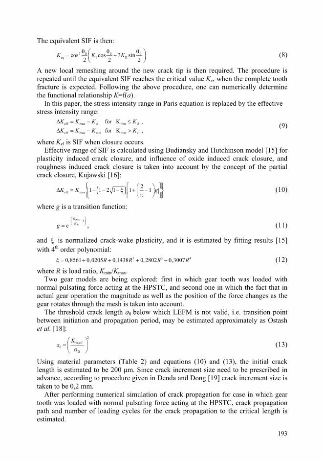
Differences in crack paths for two gear models are shown in Fig. 6a, and differences in number of loading cycles for the crack propagation to the critical length are shown in Fig. 6b.
Fig. 7. Comparison of fatigue lives
4 CONCLUSIONS The numerical model used to predict the crack initiation life in tooth root is based on the critical plane methods as the most recent and numerically most demanded method for this purpose. The fact that in actual gear operation the magnitude as well as the position of the force changes as the gear rotates through the mesh, is taken into account. In such a way, a more realistic stress cycle in gear tooth root is obtained. It resulted in significantly more exact assessments of the gear crack initiation life, and consequently in the entire fatigue life. It is reasonable, because the tensile damage parameter comprehends the amplitude of normal deformation, and the shear damage parameter comprehends the amplitude of shear deformation. Consequently, by neglecting the part of compression region stress cycle, which behave if dealing with load in the highest point of the single tooth contact, the significant error takes rise, especially in thin-rim spur gears. Beside they predict the crack initiation life, the critical plane methods predict also the initiated crack direction, which is a good base for a further analyzes of crack propagation.

197
By so completed numerical procedure, the predictions of fatigue lives and crack paths in regard to the gear tooth root stresses are obtained, which are significantly closer to experimental results then existing methods (Fig. 8).
Fig. 8. Computed service life of treated gear wheel and comparison with the available experimental results [22]
References [1] DIN 3990 Teil 3, Tragfähigkeitsberechnung von Stinräden, Berechnung der Zahnfußtrag-
fähigkeit, Beut Verlag GMBH, Berlin, (1987). [2] AGMA 6033/2-AXX, Standard for Marine Gear Units: Part 2, Rating, (1992). [3] ISO 6336, Calculation of Load Capacity of Spur and Helical Gears, International Stan-
dard, (1993). [4] Socie, D., Bannantine, J., Bulk Deformation Damage Models, Materials Science and
Engineering, A103, 3-13 (1988). [5] Shang, D. G., Yao, W. X. and Wang, D. J., "A new approach to the determination of
fatigue crack initiation size", Int. J. Fatigue, 20, 683-687 (1998). [6] Glodez, S., Flasker, J. and Ren, Z., "A new model for the numerical determination of pitt-
ing resistance of gear teeth flanks", Fatigue Fract. Engng Mater. Struct., 20, 71-83 (1997). [7] Pehan, S., Hellen, T.K., Flašker, J., Glodež, S., Numerical Methods for Determining
Stress Intensity Factors vs Crack Depth in Gear Tooth Roots, International Journal of Fatigue, 19 (10), 677-685 (1997).
[8] MSC/FATIGUE User's Manual, (1999). [9] Hoffmann, M., Seeger, T., A Generalized Method for Estimating Multiaxial Elastic-
Plastic Notch Stresses and Strains, parts 1 and 2, Journal of Engineering Materials and Technology, Transactions of the ASME, 107, 250-260 (1985).
198
[10] ASTM E 399-80, American standard. [11] FRANC2D, User’s Guide, Version 2.7, Cornell University, (2000). [12] Raju, I.S., Shivakumar, K.N., An Equivalent Domain Integral Method in the Two-
Dimensional Analysis of Mixed Mode Crack Problems, Engineering Fracture Mechanics, 37(4), 707-725, (1990).
[13] Erdogan, F., Sih, G.C., On the Crack Extension in Plates under Plane Loading and Transverse Shear, J Basic Eng D, 85, 519-525, (1963).
[15] Budiansky, B., Hutchinson, J.W., Analysis of Closure in Fatigue Crack Growth, Journal of Applied Mechanics, 45, 267-276 (1978).
[16] Kujawski, D., Enhanced Model of Partial Crack Closure for Correlation of R – Ratio Effects in Aluminum Alloys, International Journal of Fatigue, 23, 95-102 (2001).
[18] Ostash, O.P., Panasyuk, V.V., Kostyk, E.M., Assessment of the Period to Fatigue Macrocrack Initiation Near Stress Concentrators by Means of Strain Parameters, Fatigue Fract Engng Mater Struct, 22, 687-696 (1999).
[19] Denda, M., Dong, Y.F., Analytical Formulas for a 2-D Crack tip Singular Boundary Element for Rectilinear Cracks and Crack Growth Analysis, Engineering Analysis with Boundary Elements, 23, 35-49, (1999).
[20] Lewicki, D.G., Spievak, L.E., Handschuh, R.F., Consideration of Moving Tooth Load in Gear Crack Propagation Predictions, NASA/TM-2000-210227 (2000).
Author: Jelaska, Damir, Professor; Podrug, Srdjan, Assistant professor; University of Split, FESB, Croatia