gears and how their world is changing - c&s · pdf filegears –and how their world is...
TRANSCRIPT

Neville W. Sachs, P.E. (c) 2014
1
Gears – and How
Their World is
Changingby
Neville W. Sachs, P.E.
Neville W. Sachs, P.E., PLLC

Neville W. Sachs, P.E. (c) 2014
2
The Plan
• Discuss the more important terms
• Explain some types of gears and their
operation
• Describe some basic gear metallurgy and
what’s changing in gear design
• Show how they fail
• Ask some questions to see if you’re learning
anything.
My thanks to The Falk Corporation (now a division of
Rexnord) for some of the pictures and lots of education.

Neville W. Sachs, P.E. (c) 2014
3
Gear Tooth TerminologyCircular Pitch
Tip or Top Land
ADDENDUM
DEDENDUM
Active Profile
Pitch Circleor
Pitch Diameter
Root FilletRoot Clearance
Diametral Pitch (DP) = # of teeth/Pitch Diameter
PINION - the driving unit (usually smaller)GEAR or BULL GEAR - the driven unit (usually larger)
This is an involute tooth shape.
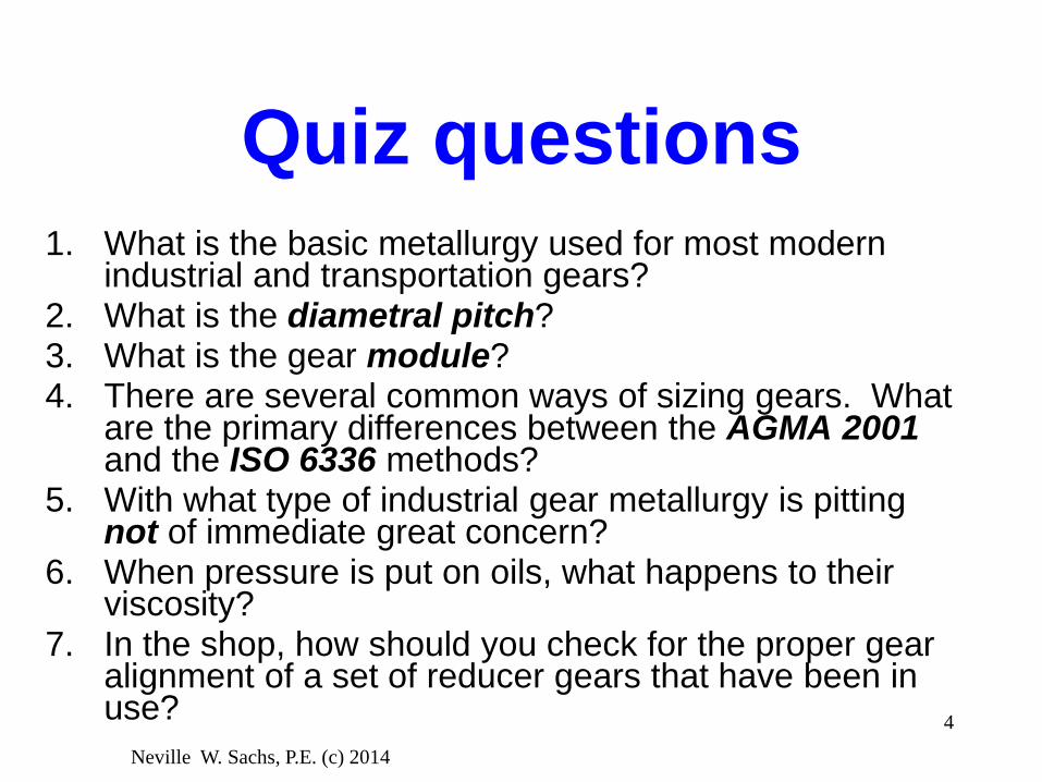
Quiz questions1. What is the basic metallurgy used for most modern
industrial and transportation gears?2. What is the diametral pitch? 3. What is the gear module?4. There are several common ways of sizing gears. What
are the primary differences between the AGMA 2001and the ISO 6336 methods?
5. With what type of industrial gear metallurgy is pitting not of immediate great concern?
6. When pressure is put on oils, what happens to their viscosity?
7. In the shop, how should you check for the proper gear alignment of a set of reducer gears that have been in use?
Neville W. Sachs, P.E. (c) 2014
4

The “gear module”Module is the metric term used for tooth size.
Larger module = larger tooth
Diametral pitch is the imperial term for tooth size.
Larger diametral pitch = smaller tooth
Module = p/π where p = circular pitch
Diametral pitch = number of teeth/pitch diameter (pd)
Neville W. Sachs, P.E. (c) 2014
5
Circular Pitch (p)
Pitch Diameter (pd)

Neville W. Sachs, P.E. (c) 2014
6
Stress on a Gear Tooth
The tooth is loaded and stressed by:
– Sliding contact causing surface fatigue damage
– Rolling contact Hertzian fatigue damage
– Bending, like a cantilever beam, that always
results in deformation and can cause breakage
Driver
- +Compression
on the unloaded side
Tensionon the contact side
Hertzian Fatigue(contact fatigue on both teeth)
-+
Surface Fatigue(only in the contact areas in tension)

Neville W. Sachs, P.E. (c) 2014
7
Tooth Contacts
• Tooth contact involves both rolling and sliding
• Understanding the action of this contact is a key to
understanding how and why gears wear.
• With involute teeth, the teeth tend to slide early in their
contact with the relative proportion of rolling increasing
until, at the pitch line the contact is pure rolling. As the teeth
go out of mesh the sliding proportion continually increases.
RollingSliding

Neville W. Sachs, P.E. (c) 2014
8
Three Stages of Contact
Gear tooth contact showing the varying rolling and sliding directions
Initial Contact
At the Pitch Line
Just before Disengagement
RollingSliding
RollingSliding
RollingSliding
none
Contact Point Action
Driver
Driver
Driver

Gear Design
Looking at the stresses shown on the
earlier slides, we see that when a gear is
designed simultaneous bending, rolling,
and sliding forces have to be considered.
In addition, the design has to plan for the
appropriate durability rating.
Neville W. Sachs, P.E. (c) 2014
9

Neville W. Sachs, P.E. (c) 2014
10
Gear Dedendum Wear
On the dedendum of the driving tooth, as the driven tooth
slides downward, the driving tooth surface is subjected to
tension, surface fatigue results, and the tooth wears. At
the same time, where the driven tooth addendum surface
is in compression, fatigue can not occur.
Driver
- +Compression
on the unloaded side
Tensionon the contact side
Hertzian Fatigue(contact fatigue on both teeth)
-+
Surface Fatigue(only in the contact areas in tension)

Design Standards
• The standards have changed about every 15 or so years
• Currently AGMA 2001 and ISO 6336 are in wide use. (AGMA = American Gear Manufacturers Association
ISO = International Organization for Standardization)
• Both allow for wear, bending and pitting resistance with equation modifiers that are similar, but not identical.
• AGMA is basically experienced-based while the ISO standard is more academically-based.
• AGMA ratings are more conservative.
• API (American Petroleum Institute) has a series of standards developed from the AGMA standards specifically for refinery and processing facilities.
Neville W. Sachs, P.E. (c) 2014
11

Design Standards• The original North American design standard was the
Lewis Equation:
Wt = (S x F x Y)/Dp
Neville W. Sachs, P.E. (c) 2014
12
Wt = transmitted load in pounds (or N)S = 1/3 tensile strengthF = Face widthY = Lewis form factor – based on the
pressure angle and # of teethDp = diametral pitch
Gear
Pressure Angle
PitchDiameters
• Pressure angle is very important.
Larger pressure angle results in
stubbier, stronger teeth, but almost
always more sliding and a little lower
efficiency.
• The tendency has been to go to
smaller teeth to improve wear rates.

Neville W. Sachs, P.E. (c) 2014
13
Common GearsStraight Cut Spur Gear
Original, noisy
Helical Smoother, but thrust loaded
Herringbone
Both correct for thrust problems
Double Helical
Original, noisy
and rough
Helical and double helical gears have multiple teeth in mesh at one time, resulting in smoother and quieter operation than
spur gears.
Most gears that look
like this are actually
double helical

Neville W. Sachs, P.E. (c) 2014
14
Some Other Common
Gears• Bevel - similar to a spur gear but
designed for a right angle drive, tends to be rough and noisy.
• Spiral Bevel - teeth are at an
angle so more than one is in mesh, similar to a helical gear
• Hypoid - a variation on spiral
bevel with the pinion centerline moved.
• Worm - unlike involute gears in
that the action only involves sliding

Worm Gears
• Usually used in high reduction applications.
• Worm gear and worm wheel contact action is
pure sliding with no rolling.
• Many lubricants used on spur and helical
gears are not suitable for worm gears both
because the sliding action results in an
extreme example of boundary lubrication and
because some common EP additives attack
the bronze worm wheels.
Neville W. Sachs, P.E. (c) 2014
15

How does a Lubricant
Prevent Wear?
• This sketch shows a greatly magnified view of two parts separated by a lubricant film. The separation is important because the greater the distance, the less the parts contact each other and less wear occurs. The Greek symbol lambda, λ, is usually used to denote the relative film thickness.
• λ is a result of the viscosity, relative speed, and the shape (relative roughness) of the parts.
Part One Surface
Part Two Surface
Ratio of the two dimensions = λ

Rolling Element Contact
and LubricationRolling element bearings and gears
in general industrial equipment
Pressures - As high as 2 GPa in the contact areas
Clearance - In the range of 0.25 to 0.51 µm
Most Important Lubricant Properties -Viscosity, Cleanliness
Action - Inlet zone viscosity transformation supports clearance
Element
Load
Exit RegionLubricant
Inlet
Travel
Hertzian Fatigue Zone(Film thickness ≈ 0.00004”)

How Pressure Affects
Viscosity
40 60 80 100 120
10
100
1000
10000
20 0
100000
140
Pressure (1000 psi)
Honey
Ab
so
lute
vis
co
sit
y (
cP
)
Antifreeze
Pressure – Viscosity Relationship for a light Mineral Oil
ASME Research Committee on Lubrication – Volume 11 (1953)

How does a Lubricant
Prevent Wear?Part One Surface
Part Two Surface
Ratio of the two dimensions = λ
Part One Surface
Part Two Surface
Ratio of the two dimensions = λ
In recent years improving the surface finish (superfinishing)has enabled gear tooth contact stresses to almost double
without having pitting.

Neville W. Sachs, P.E. (c) 2014
20
Lubricant
Films and
Wear
• Hydrodynamic Lubrication - full
separation of the two mating parts
- low wear - usually on medium to
high speed gears
• Boundary Lubrication - with thin
to non-existent films and metal-to-
metal contact, additives are critical.
(low speed and very heavily
loaded gears)
• Mixed (elastohydrodynamic) –
bearings and many plant gearing
applications fall in this category
Re
lati
ve
We
ar
Ra
te
Relative Film Thickness
Mixed
Hydrodynamic
Boundary (Elastohydrodynamic)

Neville W. Sachs, P.E. (c) 2014
21
Changing
Lubricant
Films and
Wear
• Newer synthetic lubricants (PAO,
POE, PAG, PIB) with higher
pressure-viscosity coefficients are
effecting better lubrication with
improved films, less heat
generation, and higher efficiency.
• Newer additives are improving the
boundary lubrication of low speed
gears resulting in higher contact
stresses without scuffing failure. (Scuffing is adhesive wear. Another term
that is used is galling.)
Rel
ativ
e W
ear
Rat
e
Relative Film Thickness
Mixed
Hydrodynamic
Boundary
(Elastohydrodynamic)

Neville W. Sachs, P.E. (c) 2014
22
Stress causes Elastic
Deformation
During Operation the Teeth Deform
• The gear rim and hub also deform to some
extent
• Changing loads will change this deformation
and the contact patterns

Quiz questions1. What is the basic metallurgy used for most modern
industrial and transportation gears?2. What is the diametral pitch? 3. What is the gear module?4. There are several common ways of sizing gears. What
are the primary differences between the AGMA 2001and the ISO 6336 methods?
5. With what type of industrial gear metallurgy is pitting not of immediate great concern?
6. When pressure is put on oils, what happens to their viscosity?
7. In the shop, how should you check for the proper gear alignment of a set of reducer gears that have been in use?
Neville W. Sachs, P.E. (c) 2014
23

Neville W. Sachs, P.E. (c) 2014
24
Gear Inspection Steps
1. With a bright light (and possibly a magnifying glass)
look at both the active and inactive sides of the teeth,
very carefully noting the contact patterns
2. Rotate the gears to see if the contact patterns and
surface conditions are consistent
3. Determine the tooth metallurgy
4. Decide if the wear or damage is acceptable
Gears are designed for strength and for durability

Neville W. Sachs, P.E. (c) 2014
25
Q. Why are the contact patterns
important?
1. Both root and contact stresses will vary substantially
with the accuracy of the meshing pattern.
2. Contact on the inactive flank (unloaded tooth side) from
driving forces will cause a huge increase in stresses.
– With very good lighting, start by looking carefully at the active
flank contact all the way around the gear. (Does it vary?)
– Then look at the back (inactive side) of the teeth.
A. They show us the actual loads
(forces) on the gear teeth.

Neville W. Sachs, P.E. (c) 2014
26
Look at the Active ProfileLoad Intensity vs. visible Contact Pattern for three applications
Mesh Pattern
RelativeContact Stress
Ideal Stressfor Perfect Contact
0
1
2
3
4 Actual Stress for Contact thatEnds at Tooth Edge
Actual Stress for Contact thatEnds at Mid-tooth
Don’t forget to rotate the gear to see how the
pattern varies.

A problem with contact
patterns
• As reducer marketing becomes more competitive,
gear housings have become lighter.
• What can happen to gear alignment as that lighter
housing sees the same magnitude stress as an
older heavier housing?
Neville W. Sachs, P.E. (c) 2014
27

Neville W. Sachs, P.E. (c) 2014
28
Understanding Gear
Design Loads
Ideally the load should
be absolutely constant
But there are always
variations and peak
stress is critical
Str
ess A
mp
litu
de
Time
Average tooth stress needed to rotate gear
10
20
30
Average tooth stress needed to rotate gear
Actual tooth loads
Peak tooth stress
Str
ess A
mp
litu
de
Time
10
20
30

Neville W. Sachs, P.E. (c) 2014
29
Load Variations
Average tooth stress = 14
Peak tooth stress = 18
Str
ess A
mp
litu
de
Time
10
20
Actual tooth loadsPeak tooth stress = 23
Str
ess A
mp
litu
de
Time
10
20
30
Look at the difference in peak loads with these identical
gears! Same average load, but the upper one is much
more highly stressed and will only last half as long.
Neville W. Sachs, P.E. (c) 2014
30
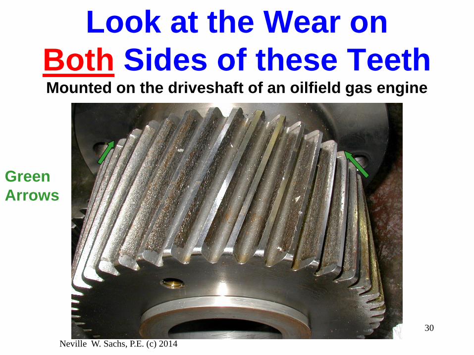
Look at the Wear on
Both Sides of these TeethMounted on the driveshaft of an oilfield gas engine
Green
Arrows
Neville W. Sachs, P.E. (c) 2014
31
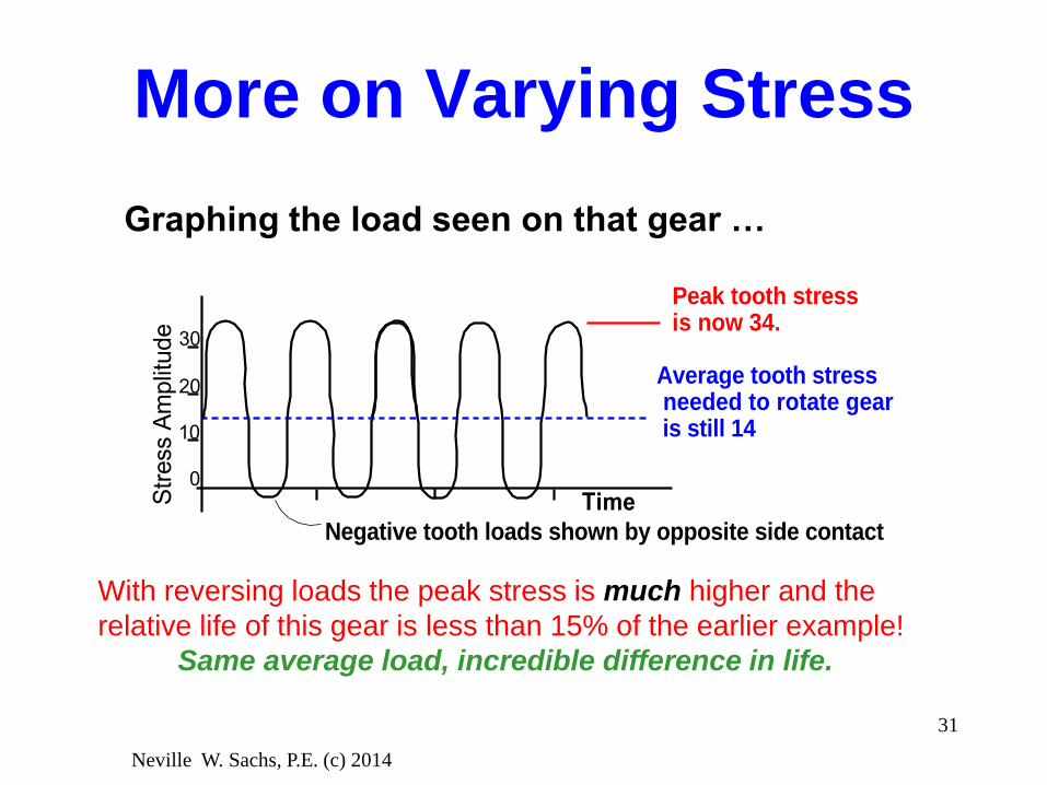
More on Varying Stress
With reversing loads the peak stress is much higher and the
relative life of this gear is less than 15% of the earlier example!
Same average load, incredible difference in life.
Negative tooth loads shown by opposite side contact
Average tooth stress needed to rotate gear is still 14
Peak tooth stressis now 34.
Str
ess A
mplit
ude
Time
10
20
30
0
Graphing the load seen on that gear …

Neville W. Sachs, P.E. (c) 2014
32
Some Sources of
Load Variations• Coupling Misalignment
• Gear Misalignment
• Input Torque Changes
• Pinion and Gear Eccentricity
• Machining Errors
• Torsional Vibration and Resonances

Neville W. Sachs, P.E. (c) 2014
33
Tooth Alignment is
Critical
With Hertzian fatigue stresses, the fatigue life is a
function of 1/load3.33+. As the tooth misalignment
becomes worse, the life decreases rapidly.
Mesh Pattern
RelativeContact Stress
Ideal Stressfor Perfect Contact
0
1
2
3
4 Actual Stress for Contact thatEnds at Tooth Edge
Actual Stress for Contact thatEnds at Mid-tooth

Neville W. Sachs, P.E. (c) 2014
34
Some Gear Materials• Wood
• Bronze
• Cast Iron
• A Variety of Steels -
Hardened and Unhardened
• Plastics
• …

Neville W. Sachs, P.E. (c) 2014
35
Steel Gears - with VERY
Different Metallurgies
Case Hardening - may be from furnace, flame, induction, … The case may be carburized, nitrided, carbonitrided, ...
CASE or SURFACE HARDENED TOOTH
THROUGH-HARDENED TOOTH
Hard Case - usually between HRc 42 and HRc 60
Soft Core
Same hardness throughout(May or may not be hardened)
Commonly – case at HRC
55-60 and core at HRC
30-40
Almost always
below HRC 40
Neville W. Sachs, P.E. (c) 2014
36
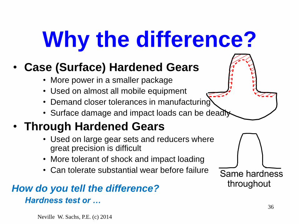
Why the difference?• Case (Surface) Hardened Gears
• More power in a smaller package
• Used on almost all mobile equipment
• Demand closer tolerances in manufacturing
• Surface damage and impact loads can be deadly
• Through Hardened Gears• Used on large gear sets and reducers where
great precision is difficult
• More tolerant of shock and impact loading
• Can tolerate substantial wear before failure Same hardness throughout
How do you tell the difference?Hardness test or …

Neville W. Sachs, P.E. (c) 2014
37
North American Reducer Gear
Metallurgy – changes over the years
• Essentially every fixed reducer made before 1960 had through hardened gears. (Cars and trucks have had case hardened gears since the 1930’s.)
• Starting in the early 1960’s small reducers, less than 40 hp, because of the changes in the rebuilt European gear industry, have used case hardened gears and an occasional large reducer also had case hardened pinions.
• By the early 1980’s, many 200 hp reducers had surface hardened gears.
• Today, essentially everything 1000 hp and smaller has case hardened gears.

Neville W. Sachs, P.E. (c) 2014
38
What Affects Gear
Life?• Load
• Load Distribution (Alignment)
• Materials
• Temperature
• Lubricant Film Thickness
• Gear Tooth Geometry, Finish, and
Hardness
Neville W. Sachs, P.E. (c) 2014
39
Pitting and pitting
resistance• The result of Hertzian fatigue loads.
• Acceptable only on through hardened gears.
– Three basic types - corrective, destructive, and normal dedendum wear
• Harder gear materials are more resistant to pitting.
• Pitting is frequently a disaster warning on surface (case) hardened gears – because the core is much weaker than the case.

Neville W. Sachs, P.E. (c) 2014
40
Three Types of Pitting• Corrective - “break-in” that eventually
reduces wear rates. (The corrective pitting
rate decreases with time.)
• Normal dedendum wear - the result of
millions of fatigue cycles.
• Destructive - severe fatigue loading that
continually worsens and rapidly destroys the
teeth.
They all really just define the different wear rates.

Neville W. Sachs, P.E. (c) 2014
41
Where Pitting is
usually FoundADDENDUM
PITCH LINE
DEDENDUMPITCH CIRCLE
Corrective Pittin
g or
Destructive Pitting
Normal Dedendum Wear
Active profile!

Neville W. Sachs, P.E. (c) 2014
42
Corrective vs.
Destructive PittingP
itting S
everity
Time (generally a few weeks)
Corrective
DestructiveBut all pitting is wear
and the question should
be “How long do the
gears have to last”?
Neville W. Sachs, P.E. (c) 2014
43
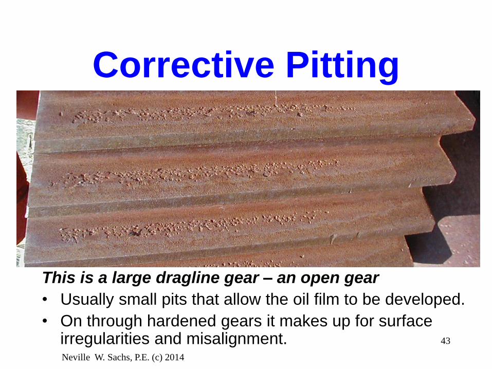
Corrective Pitting
This is a large dragline gear – an open gear
• Usually small pits that allow the oil film to be developed.
• On through hardened gears it makes up for surface irregularities and misalignment.

Corrective Pitting
Neville W. Sachs, P.E. (c) 2014
44
Oil spray pipe
Usually small pits that allow the oil film to be developed.On through hardened gears it makes up for surface irregularities and misalignment.

Neville W. Sachs, P.E. (c) 2014
45
Normal Wear -
Dedendum PittingCompressor drive gear
after 10 years at 1800
rpm.
Yes, it will whine but
does it have to be
changed? What would
you do?

Normal dedendum wear of a
through hardened gear
Neville W. Sachs, P.E. (c) 2014
46

Neville W. Sachs, P.E. (c) 2014
47
Destructive Pitting
Can’t develop a lubricant film. As a result the gear wears
rapidly and gets progressively rougher and noisier.
A Falk photo.

Neville W. Sachs, P.E. (c) 2014
48
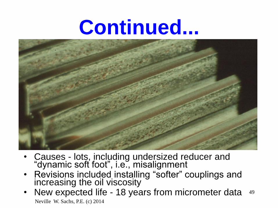
Corrective
Pitting
Example
Double reduction reducer
with corrective pitting on
low speed gear. Original
gears only lasted three
years.
Neville W. Sachs, P.E. (c) 2014
49
Continued...
• Causes - lots, including undersized reducer and “dynamic soft foot”, i.e., misalignment
• Revisions included installing “softer” couplings and increasing the oil viscosity
• New expected life - 18 years from micrometer data

Neville W. Sachs, P.E. (c) 2014
50
Monitoring normal dedendum wear
on through-hardened gears

Neville W. Sachs, P.E. (c) 2014
51
Monitoring normal dedendum wear
on through-hardened gears
Set the depth about 10% below the pitch
line and periodically measure the tooth
width with a gear tooth micrometer.
This allows you to do predictive
maintenance and monitor the effects of
changes in lubrication and operation!

Neville W. Sachs, P.E. (c) 2014
52
Alignment Disaster
A. The choice is either broken teeth or rapid wear
B. Don’t forget the two basic metallurgies

Neville W. Sachs, P.E. (c) 2014
53
More on Alignment
When we started working on gears, with open gear
sets, 1/2 tooth contact was OK. Later we realized the
how important good alignment is.
Now, on running gears, we use an infrared scanner
and try for no more than a 100 F difference across the
face of the pinion.
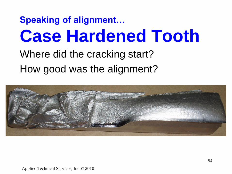
Speaking of alignment…
Case Hardened ToothWhere did the cracking start?
How good was the alignment?
Applied Technical Services, Inc.© 2010
54

Neville W. Sachs, P.E. (c) 2014
55
Surface (Case)
Hardened GearsMicropitting - from heavy loads, hydraulic action, and
Hertzian fatigue
Neville W. Sachs, P.E. (c) 2014
56
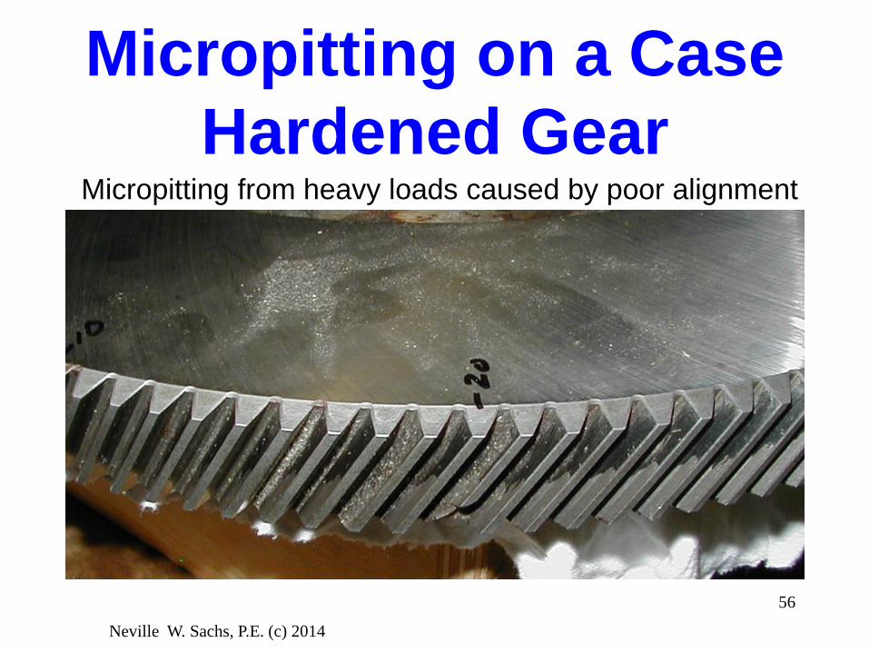
Micropitting on a Case
Hardened GearMicropitting from heavy loads caused by poor alignment

Uniform Micropitting Bands


Applied Technical Services, Inc.© 2010
59
Rippling of a Case
Hardened Gear
Can you see the distorted reflection of the camera?

Applied Technical Services, Inc.© 2010
60
Case Hardened Gears
Rippling that has progressed to pitting and
serious spalling

Neville W. Sachs, P.E. (c) 2014
61
Comparison Review
• Through Hardened - Tough, good impact
resistance, relatively tolerant of poor
lubrication and abuse, corrective pitting can
improve contact pattern, larger gear to handle
the same loads.
• Surface Hardened - More power in same
package, requires very good alignment and
lubrication, pitting is a sign of excessive loads
and can be a danger warning.

Neville W. Sachs, P.E. (c) 2014
62
Overload resulting in
Rolling (Plastic Flow)

Neville W. Sachs, P.E. (c) 2014
63
Case Crushing from
Overload

Neville W. Sachs, P.E. (c) 2014
64
This large spall indicates a
metallurgical problem

Neville W. Sachs, P.E. (c) 2014
65
Manufacturing Problemwith an intermediate Pinion Gear

Neville W. Sachs, P.E. (c) 2014
66
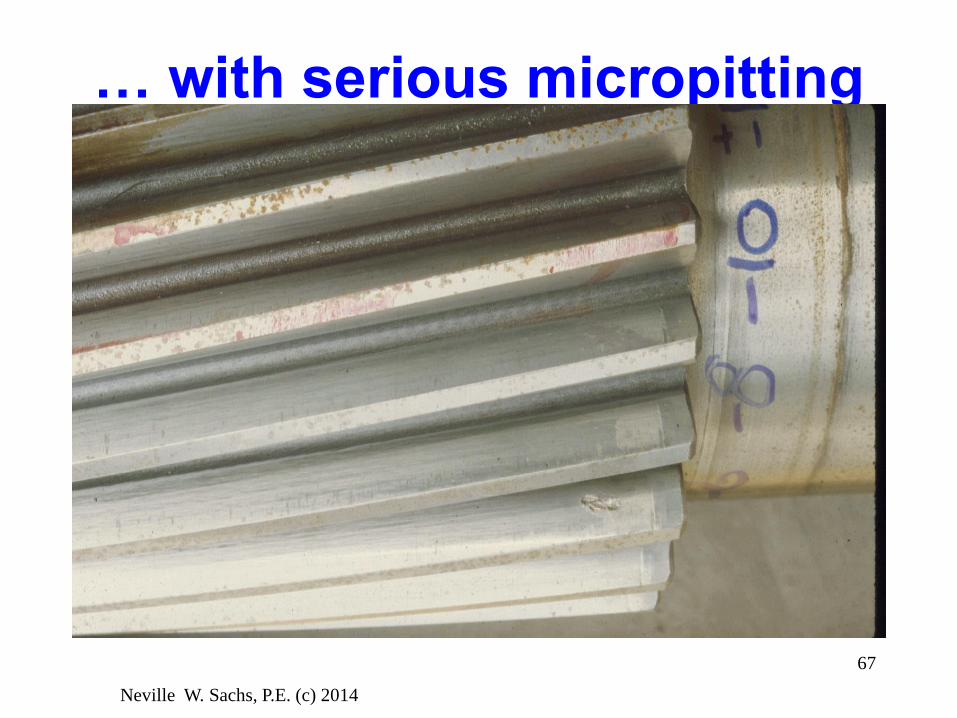
Misalignment
Neville W. Sachs, P.E. (c) 2014
67
… with serious micropitting

Quiz questions1. What is the basic metallurgy used for most modern
industrial and transportation gears?2. What is the diametral pitch? 3. What is the gear module?4. There are several common ways of sizing gears. What
are the primary differences between the AGMA 2001and the ISO 6336 methods?
5. With what type of industrial gear metallurgy is pitting not of immediate great concern?
6. When pressure is put on oils, what happens to their viscosity?
7. In the shop, how should you check for the proper gear alignment of a set of gears in a reducer that has been in use?
Neville W. Sachs, P.E. (c) 2014
68

Neville W. Sachs, P.E. (c) 2014
69
Thank you for
listening!
Any questions??