general catalog of pneumatic/ fluid transport tubing
TRANSCRIPT

Tubing, Fitting and CHEMIFIT
TM
Tubing, Fittingand CHEMIFITTM
General Catalog of Pneumatic/Fluid Transport Tubing
B-TU-17-E

Safety NoteThis Safety Note provides indications on the correct use of the product in order to prevent harm to people and property. The indications are classified into three categories, “danger”, “warning”, and “caution”, depending on the level of potential harm due to improper use. Each category contains important instructions on safety that should be followed in addition to the latest ISO 4414(*1), JIS B 8370(*2), ISO 4413 (*3), and JIS B 8361 (*4).
(*1) ISO 4414 Pneumatic fluid power…Recommendations for the application of equipment to transmission and control systems.
(*2) JIS B 8370 Pneumatic System General Rules
(*3) ISO 4413 Hydraulic fluid power…General rules for the application of equipment to transmission and control systems.
(*4) JIS B 8361 Hydraulic System General Rules
* Specifications in this catalog are subject to change without notice.* Secondary use of information in this catalog for copy, distribution and sale without permission is prohibited.
Common handling instructions for products in catalog
For more safety information, please read the handling instructions carefully. A safety note for each product is also given on its product page and instruction page.
Nitta Corporation is not liable for damage caused intentionally and unintentionally by customers, damage due to products other than Nitta’s including software failure, and damage due to natural disasters.
Nitta Corporation is not liable for damage due to usage that is not explained or specified in this catalog and instruction manual.
Nitta Corporation is not liable for damage without any clear record of its liability even if the damage occurred after the customer contacts Nitta.
Nitta Corporation is not liable for collateral damage such as loss of business income and business termination due to using Nitta’s products or due to inability to use our products.
Exclusion of Liability
DANGERWhere inappropriate use of this equipment may cause death or severe injury and where immediate warning of a dangeroussituation is mandated.
WARNINGWhere inappropriate use of this equipment may cause death or severe injury.
CAUTIONWhere inappropriate use of this equipment may cause minor injury.
1
2
3
4

INDEXCommon Handling Instructions
Index: Index of All Products P.2
Combination List of Tubing and Fitting (Working temperature range) P.8
Tubing Products P.10 Handling instructions INDEX
Tubing Polyurethane tubing/Nylon tubing
Flexible fluorocarbon resin bilayer tubing/Flame-resistant tubing/Antistatic tubing
Shape-keeping tubing/Polybutene tubing
Clean tubing Clean, Antistatic tubing/Polyolefin tubing/Fluorocarbon resin tubing
Processed tubing Polyurethane coil tubing/Polyurethane multi-line tubing/Nylon coil tubing/Multi-pack tubing
Tubing Fitting Products P.34 Handling instructions INDEX
PushOne series PushOne A series/PushOne A series(mini type)
PushOne E series/PushOne E series (brass body type)
QuickSeal series Insertion type (brass)/Insertion type (stainless)/Insertless type
DK tubing dedicated type/Nylon coil tubing dedicated type
Chemifit series Chemifit C1 series/Chemifit C1S series
Chemifit CSE series/Chemifit CP series
Bamboo-shoot series Barb type
Control Switch and Detachable Products P.134 Handling instructions INDEX Chemifit C1 speed controller/Compact speed controller/Speed controller
Ball valve/Throttle valve/Miniature valve
Valve built-in connector/Q.D.C 101 series/Q.D.C 103 series
Jigs, Tools and Accessories P.158 INDEX Tube cutter/FW tubing outer cover peeling cutter/FWU tubing outer cover peeling cutter
Spatter cap/Off tool/Tube reel
Air balancer/Tool balancer
Technical Information P.162 INDEX Speed controller flow characteristics/Effective sectional area/Negative-pressure performance list/Instruction manual
Reference P.188 INDEX TES Tubing Technology Data/Applied standard list/Screw standard list/UL-94 standard flame test/Table of full scale tubing and
screw/Unit conversion table/
Chemical resistance specification table/
Product Number Index P.205
Tub
ing
Cle
an
tub
ing
Pu
sh
On
efi
ttin
gQ
uic
kS
ea
lfi
ttin
gB
amb
oo
-sh
oo
t fi
ttin
gC
ontr
ol s
witc
h/D
etac
habl
ese
ries
Cle
an f
itti
ng
/C
hem
ifit
Jig
/To
ol/
Accesso
ryR
efer
ence
Pro
cess
edtu
bin
gTe
chn
ical
info
rmat
ion

Tub
ing
Cle
an
tub
ing
Pu
sh
On
efi
ttin
gQ
uic
kS
ea
lfi
ttin
gB
amb
oo
-sh
oo
t fi
ttin
gC
ontr
ol s
witc
h/D
etac
habl
ese
ries
Cle
an f
itti
ng
/C
hem
ifit
Jig
/To
ol/
Accesso
ryR
efer
ence
Pro
cess
edtu
bin
gTe
chn
ical
info
rmat
ion
Polyurethane Tubing
P.12 P.13 P.14
Nylon Tubing
P.15 P.16 P.17
Flexible Fluorocarbon Resin Bilayer Tubing
P.18
Flame-resistant Tubing
P.20
P.21 P.22
Antistatic Tubing
P.23
Shape-keeping Tubing Polybutene Tubing
P.24
P.24
For general air pressureWell balanced be- tween flexibility and
pressure-resistance performance
For general air pressureUsable in higher air
pressure range than U2
For general air pressure(Ultra flexible)High workability
with low bending stress
For general air pressure (electrically conductive)Conductive
polyurethane elastomer for spark prevention
For retaining shapePiping shape is keptEasy construction
compared to copper
For food processing machinesSuitable for high
temperature antimicrobi-al cleaning of food processing machines
Compliant with the 370th notification of Ministry of Health and Welfare, Japan
For multi purpose pipingHigh oil resistance
and chemical resistance
For coating (flexible)Bilayer structure of inner (special
fluorocarbon resin) and outer (special nylon resin) layers
High flexibility
Flame-resistant Tubing
P.19
For spot welding piping (flexible)High flame resistance (Compliant with
V-0 of UL94 standard) Improves work efficiency with excellent
flexibility, abrasion resistance, and sliding properties while requiring no peeling during pipe installation
For spot welding pipingHigh flame
resistance (Compliant with V-0 of UL94 standard)
High flexibility
For spot welding piping(bilayer)High flame
resistance (Compliant with V-0 of UL94 standard)
Bilayer structure with flame-resistant resin inner and outer layers
For spot welding piping (flexible)High flame resistance
(Compliant with V-0 of UL94 standard)
Bilayer structure with polyurethane tubing inner layer, high flexibility
Soft nylonHigh workability
with low bending stress
Hard (unplasti-cized) nylon Unplasticized nylon
2
Tubing
U2 U1 U5
N2 N5 N1
TESTES FUKFUK
FS FW FWU
UE DKDK PBPB

Tub
ing
Cle
an
tub
ing
Pu
sh
On
efi
ttin
gQ
uic
kS
ea
lfi
ttin
gB
amb
oo
-sh
oo
t fi
ttin
gC
ontr
ol s
witc
h/D
etac
habl
ese
ries
Cle
an f
itti
ng
/C
hem
ifit
Jig
/To
ol/
Accesso
ryR
efer
ence
Pro
cess
edtu
bin
gTe
chn
ical
info
rmat
ion
For clean, heat-resis-tant, cold-resistant, chemical-resistant usePFA resin tubing with high
chemical resistanceProduced, end-sealed,
heat-sealed for shipping in a cleanroom
For clean, heat-resis-tant, cold-resistant, chemical-resistant useFEP resin tubing with high
chemical resistanceProduced, end-sealed,
heat-sealed for shipping in a cleanroom
Fluorocarbon Resin Tubing
P.28 P.29
For clean pipingSurface resistivity of
1011Ω/sp or lower Does not allow dust to gather
No contamination with particles
Can be used with clean air and fluorine-based refrigerants
Polyurethane coilCoil tubing for general air
pressure
Polyurethanemulti-lineMulti-core welding tubing for
general air pressure
Nylon coilSingle core nylon coil tubing
with strong elasticity
Bundled tubingProcessed tubing for multi
piping (Made to order)
Clean, Antistatic Tubing
P.25
For clean pipingSuitable for fluids
such as clean air, N2 gas, pure water and various chemical liquids
Environment-friend-ly eco tubing
Produced, end-sealed, heat-sealed for shipping in a cleanroom
For clean piping (flexible)Suitable for fluids such
as clean air, N2 gas, pure water and various chemical liquids
Environment-friendly eco tubing
Produced, end-sealed, heat-sealed for shipping in a cleanroom
High workability with low bending stress
Polyolefin Resin Tubing
P.26P.27
Polyurethane Coil Tubing
P.30
Multi-line Tubing
P.31
Nylon Coil Tubing
P.32
Multi-pack Tubing
P.33
3
Clean Tubing
Processed Tubing
TATA TPTP
ES PL PN
UCUSCUMC
S 1213
UCUSCUMC
UMLUML
S 1213

Tub
ing
Cle
an
tub
ing
Pu
sh
On
efi
ttin
gQ
uic
kS
ea
lfi
ttin
gB
amb
oo
-sh
oo
t fi
ttin
gC
ontr
ol s
witc
h/D
etac
habl
ese
ries
Cle
an f
itti
ng
/C
hem
ifit
Jig
/To
ol/
Accesso
ryR
efer
ence
Pro
cess
edtu
bin
gTe
chn
ical
info
rmat
ion
PushOneTM A Series
P.36
P.50
PushOneTM E Series
P.56
P.72
QuickSeal Series
P.76 P.88 P.94
QuickSeal Series
P.102P.98
For general air pressurePushOne
connectionHigh flame
resistance (Compliant with V-0 of UL94 standard)
Electroless nickel plated
For general air pressurePushOne
connectionFlame retardance
(Compliant with V-0 of UL94 standard)
Electroless nickel plated
For multi-pur-pose pipingScrew-in typeHigh sealing
performanceOnly connector is
sealed
For general air pressureScrew-in type
For general air pressureScrew-in type
For multi-pur-pose pipingScrew-in typeHigh sealing
performanceMade of SUS304
For general air pressureScrew-in typeFor large flow
volume
For general air pressurePushOne
connectionElectrically
conductive if combined with UE tubing
High flame resistance (Compliant with V-0 of UL94 standard)
For general air pressurePushOne
connectionCompactElectroless nickel
plated
4
PushOneTM Series
QuickSeal Series
Brass body type
Insertion type (brass)
Insertion type (stainless)
DK tubingdedicated type
Nylon coil tubingdedicated type
Insertless type
Brass body type
Mini type
Insertion type (brass)
Insertion type (stainless)
DK tubingdedicated type
Insertless type
Nylon coil tubingdedicated type

Tub
ing
Cle
an
tub
ing
Pu
sh
On
efi
ttin
gQ
uic
kS
ea
lfi
ttin
gB
amb
oo
-sh
oo
t fi
ttin
gC
ontr
ol s
witc
h/D
etac
habl
ese
ries
Cle
an f
itti
ng
/C
hem
ifit
Jig
/To
ol/
Accesso
ryR
efer
ence
Pro
cess
edtu
bin
gTe
chn
ical
info
rmat
ion
ChemifitTM C1 Series ChemifitTM C1S Series
P.104P.112
P.118
ChemifitTM CSE Series ChemifitTM CP Series
P.126
Bamboo-shoot Series
P.132
For clean air, pure water, chemical liquid piping Made in oil-free processPushOne connectionNonmetal liquid-contact
surfaceHigh performance, free of
dust and contaminationDouble clean package
Bamboo-shoot fittingBamboo-shoot typeSealing-processed R threadVarious shape combinations
available
For clean air, pure water, chemical liquid piping Threaded fitting made of
polypropylene resinMade in oil-free processHighly smooth inner surfaceHigh performance, free of
dust and contamination
For clean air, pure water, chemical liquid piping Screw-in type fitting made of
SUS316High workability of tubing
with assembly nutUniform workability for
connecting tubingNo rotation of tubing when
tightening nutMade in oil-free processHigh sealing performanceNo need for additional
tightening of assembly nut
For clean air, pure water, chemical liquid piping Made in oil-free processPushOne connectionSUS304 screw Double clean packageHigh performance, free of
dust and contamination
5
ChemifitTM Series
Bamboo-shoot Series
Barb type
Oil-free processing, clean wrapping and clean packageUltrasonic cleaning with no oil and fat used for assembling in a cleanroom.
Work process in a cleanroom
Cleaning
Shipping
Ultrasonic cleaningPackaging in small bag
Heat sealing
Packaging in large bag
Zipper sealingDry Assembling or setting
Packaging in presentation box or outer case

Tub
ing
Cle
an
tub
ing
Pu
sh
On
efi
ttin
gQ
uic
kS
ea
lfi
ttin
gB
amb
oo
-sh
oo
t fi
ttin
gC
ontr
ol s
witc
h/D
etac
habl
ese
ries
Cle
an f
itti
ng
/C
hem
ifit
Jig
/To
ol/
Accesso
ryR
efer
ence
Pro
cess
edtu
bin
gTe
chn
ical
info
rmat
ion
Control Series
Control Series
Compact Speed Controller
Speed Controller
P.138
P.140
Control Series
P.136
Switch Series
ChemifitTM C1 Speed Controller
Ball Valve
P.143
Control Series
Throttle Valve Miniature Valve
P.146 P.148
Detachable Series
Q.D.C 101 Q.D.C 103
P.152 P.155
Detachable Series
Valve Built-in Connector
P.151
Smaller than the convention-al model
PushOne connectionElectroless nickel platedSealing-processed R thread
Suitable for environment (atmosphere) that requires chemical resistance
PushOne connection Inline type (ESU) allows
central control on piping line
PushOne connection Inline type (ASU) allows
central control on piping lineElectroless nickel plated
Enables compact pipingPushOne connectionPosition of handle can be
changedNickel plated
Fine control of flow rate Inline type (ANU) allows
central control on piping linePushOne connectionElectroless nickel plated
Opening/Closing inside valbe by detaching tubing
PushOne connectionElectroless nickel plated
Easy flow rate controlPushOne connection for
millimeter size type (quick seal type for inch size type)
Compact coupler for air pressurePush-To-Connect typeAutomatic opening/closing
valve inside the couplerPushOne fitting integrated
types available
Micro coupler for air and oil pressurePush-To-Connect typeAutomatic opening/closing
valve inside the couplerSmaller than 101 seriesElectroless nickel plated
6
Control Switch and Detachable Series

Tub
ing
Cle
an
tub
ing
Pu
sh
On
efi
ttin
gQ
uic
kS
ea
lfi
ttin
gB
amb
oo
-sh
oo
t fi
ttin
gC
ontr
ol s
witc
h/D
etac
habl
ese
ries
Cle
an f
itti
ng
/C
hem
ifit
Jig
/To
ol/
Accesso
ryR
efer
ence
Pro
cess
edtu
bin
gTe
chn
ical
info
rmat
ion
Tube Cutter
P.159
Hose Cutter
P.159
FW/FWU Tubing Outer Cover Peeling Cutter
P.160 P.160
Spatter Cap
P.161
Off Tool
P.161
Tube Reel
P.161
P.159
Compact, handy-to-carry, lightweight tube cutter
The blade is replaceable. It comes with three spare blades
Can cut tubes of up to 16mm diameter
Highly durable nipper-type tube cutter
Can cut tubes of up to 13mm diameter
Easy peeling of FW tubing outer cover
Easy peeling of FWU tubing outer cover
Highly durable nipper-type tube cutter
Can cut tubes of up to 20mm diameter
Protects PushOne connecting part from spatter (hot wasted metal), etc
CCP can be attached after connecting tubing
Easy removal of PushOne fitting from tubing
Easy handlingRecycled
polypropylene resin used
7
Jigs, Tools and Accessories
TC04
TC02TC03
CP•CPFW•CPPCP•CPFW•CPP EOTEOT PTRPTR
TC02UTC03U
TC01 HC03

8
A series
Combination List of Tubing and Fitting (Working temperature range)See “Chemical resistance specification table” at the end of this catalog if a chemical is contained in fluid or atmosphere. Proper usage should be judged based on your use condition data.Before using the tubing and fitting in combination, read the handling instructions of each product carefully.
(*1) If spatter (hot wasted metal) is likely to cling to the connection part of tubing, use a brass tubing instead of a nylon one.(*2) This is a combination of clean and general types. When using them together in a clean environment, be aware of how this could lower the clearliness level.(*3) Use a brass body type of connector and internal connector to keep fittings and the tubing electrically conductive.(*4) Use water-based paint, or aliphatic or aromatic carbon hydride solvent. Contact us for other types of fluid.
−20∼+80
−20∼+80
−20∼+80 −20∼+80
−20∼+80
−20∼+80
−20∼+80
−20∼+80
−20∼+80
−20∼+80
−20∼+80
−20∼+80
−20∼+80
−20∼+80
−20~+80
−20∼+80
−20∼+80
−20∼+80
−20∼+80(∗2)
−20∼+80(∗2)
−20∼+80(∗2)
−20∼+80(∗2)
−20∼+80(∗2)
−20∼+80(∗2)
−20∼+80(∗2)
−20∼+80(∗2)
−20∼+80(∗2)
−20∼+80(∗2)
0∼+40
0∼+40
0∼+40
0∼+40(∗2)
0∼+40(∗2)
0∼+40(∗2)
0∼+40(∗2)
−20∼+80
0∼+40
0∼+40
0∼+40
0∼+40
0∼+40
−20∼+80
−20∼+80
−20∼+80
−20∼+80 −40∼+80
−40∼+80
0∼+50
0∼+50
0∼+50
0∼+70
0∼+70
0∼+70
−40∼+80
−40∼+80 −40∼+100
−40∼+80 −40∼+100
−40∼+80 −40∼+100
−40∼+80 −40∼+100
−40∼+80 −40∼+100
−40∼+80 −40∼+100
0∼+40
−40∼+60
−40∼+100
−40∼+100
−40∼+80
−40∼+100
−40∼+100
−40∼+80
−10∼+80 −10∼+90
0∼+70 0∼+90
−0∼+70(∗1)
−0∼+50(∗1)
−40∼+80(∗2)
−40∼+80(∗2)
−40∼+100(∗2)
0∼+70(∗2)
0∼+70(∗2)
0∼+100(∗2)
0∼+70(∗2) 0∼+80(∗2)
−40∼+80
−40∼+80
−40∼+80
−40∼+80
−40∼+80(∗2)
−40∼+80(∗1)
−40∼+80(∗1)
−40∼+80
0∼+70(∗2)
−40∼+80(∗2)
−40∼+100(∗1)
−20∼+80(∗3)
−20∼+80
−20∼+80
−20∼+80
−20∼+80
−20∼+80
−20∼+80
−20∼+80
−20∼+80
−20∼+80(∗2)
−20∼+80(∗2)
−20∼+80(∗2)
−20∼+80(∗2)
0∼+40
0∼+40
0∼+40
0∼+40(∗2)
0∼+40(∗2)
0∼+40(∗2)
0∼+40(∗2)
−20∼+80
0∼+40
0∼+40
0∼+40
0∼+40
0∼+40
−20∼+80(∗3) −20∼+80(∗3) −20∼+80(∗3)
U2
U1
Polyurethanetubing
UE
U5
N5
N2Nylontubing
N1
TES
DK
PB
FS
FW
Flexiblefluorocarbonresin tubing
Shape-keeping tubing
Polybutenetubing
Flame-resistanttubing
FWU
PL
PN
TA
Polyolefin resintubing
Fluorocarbonresin
tubingTP
UC
USCPolyurethaneprocessed
tubing UMC
UML
SNylon coiltubing
Air
Water
Air
Water
Air
Air
Air
Water
General operating oil
Air
Water
General operating oil
Air
Water
General operating oil
Air
Water
Air
Air
Water
Air
Water
Air
Water
Air
Water
Air (Clean air)
Water (pure water)
Air (Clean air)
Water (pure water)
Air (Clean air)
Water (pure water)
Air (Clean air)
Air
Air
Air
Air
Air
Water (pure water)
Water-based paint (∗4)
PushOne seriesSeries
Fittingtype
Tubing type
Product
Fluid
E series Insertion type (brass) Insertlesstype
Insertiontype
(SUS304)
DKfittings
Nylon coilfittings
Barbtypemini type Brass body type
Nylon sleeve Brass sleeve
QuickSeal series Bamboo-shoot series
0∼+70(∗1)
−40∼+80
−40∼+80
0∼+50
0∼+50
0∼+50
0∼+70
0∼+70
−40∼+80
−40∼+80
−40∼+80
−40∼+80
−40∼+80
−40∼+80
−40∼+80
0∼+70
0∼+40
−40∼+80
−10∼+80
0∼+70
−40∼+80
−40∼+80(∗2)
−40∼+80(∗2)
0∼+70(∗2)
0∼+70(∗2)
0∼+70(∗2)
−40∼+80
−40∼+80
−40∼+80
−40∼+80
−40∼+80(∗2)
0∼+70(∗2)
−40∼+80(∗2)
0∼+70
0∼+50
−40∼+80
−40∼+80
−40∼+80
ESAntistatic tubing Air (Clean air) −40∼+80(∗2)
Fluorine-basedinert fluid −40∼+50(∗2)
0∼+70
−20∼+80 −20∼+80
0∼+40
−40∼+80(∗1)−20∼+80
0∼+40FUK
Air
Water 0∼+60(∗1)
−40∼+80
0∼+60
Tub
ing
Tub
ing
Cle
an t
ub
ing
Cle
an
tub
ing
Pu
sh
On
efi
ttin
gQ
uic
kS
ea
lfi
ttin
gB
amb
oo
-sh
oo
t fi
ttin
gC
ontr
ol s
witc
h/D
etac
habl
ese
ries
Cle
an f
itti
ng
/C
hem
ifit
Jig
/To
ol/
Accesso
ryR
efer
ence
Pro
cess
edtu
bin
g
Pro
cess
ed t
ub
ing
Tech
nic
alin
form
atio
n

9
−20∼+80
−20∼+80
−20∼+80
−20∼+80
0∼+80
0∼+80
0∼+80
−60∼+80
−60∼+80
−65∼+260
−40∼+80(∗2)
−40∼+80(∗2)
−40∼+80(∗2)
−40∼+80(∗2)
0∼+80
0∼+80
0∼+100
−20∼+80
−20∼+80
−20∼+80
0∼+80
+5∼+60
+5∼+60
+5∼+60
+5∼+60
+5∼+60
+5∼+60
+5∼+60
+5∼+60
+5∼+60(∗2)
+5∼+60(∗2)
0∼+800∼+80
−20∼+80(∗2)
−20∼+80(∗2) −40∼+80(∗2)
−40∼+80(∗2)
−40∼+60(∗2)
−40∼+60(∗2)
−40∼+100(∗2)
−10∼+90(∗2)
0∼+70(∗2)
0∼+90(∗2)
0∼+40(∗2)
0∼+50(∗2)
0∼+50(∗2)
−20∼+80
−20∼+80
−20∼+80
−20∼+80
0∼+80
0∼+80
0∼+80
0∼+80
−20∼+80(∗2)
−20∼+80(∗2)
0∼+50(∗2)
0∼+50(∗2)
0∼+50(∗2)
0∼+50(∗2)
−20∼+80
−20∼+80
−20∼+80
−20∼+80
−20∼+80
−20∼+80
−20∼+80
−20∼+80
−20∼+80(∗2)
−20∼+80(∗2)
−20∼+80(∗2)
−20∼+80(∗2)
0∼+40
0∼+40
0∼+40
−0∼+40(∗2)
−0∼+40(∗2)
−0∼+40(∗2)
−0∼+40(∗2)
−20∼+80
0∼+40
0∼+40
0∼+40
0∼+40
0∼+40U2
U1
UE
U5
N5
N2
N1
TES
DK
PB
FS
FW
FWU
PL
PN
TA
TP
UC
USC
UMC
UML
S
Air
Water
Air
Water
Air
Air
Air
Water
General operating oil
Air
Water
General operating oil
Air
Water
General operating oil
Air
Water
Air
Air
Water
Air
Water
Air
Water
Air
Water
Air (Clean air)
Water (pure water)
Air (Clean air)
Water (pure water)
Air (Clean air)
Water (pure water)
Air (Clean air)
Air
Air
Air
Air
Air
Water (pure water)
Water-based paint (∗4)
Fittingtype
Tubingtype
Product
Fluid
C1 series C1S series CSE series CP seriesCompact
speedcontroller PushOne type QuickSeal type
Clean fitting, Chemifit series Control switch, detachable series
+5∼+60
+5∼+60
+5∼+60
+5∼+60
+5∼+60
+5∼+60
Chemifit C1speed
controller
+5∼+60
+5∼+60
+5∼+60
+5∼+60
+5∼+60
+5∼+60
+5∼+60
+5∼+60
+5∼+60
+5∼+60(∗2)
+5∼+60(∗2)
+5∼+60(∗2)
+5∼+60(∗2)
+5∼+60(∗2)
+5∼+60(∗2)
Speedcontroller
Ball valve
−20∼+80
−20∼+80
−20∼+80
−20∼+80
−20∼+80
−20∼+80
−20∼+80
−20∼+80
−20∼+80(∗2)
−20∼+80(∗2)
−20∼+80(∗2)
−20∼+80(∗2)
0∼+40
0∼+40
0∼+40
−0∼+40(∗2)
−0∼+40(∗2)
−0∼+40(∗2)
−0∼+40(∗2)
−20∼+80
0∼+40
0∼+40
0∼+40
0∼+40
0∼+40
−20∼+80
−20∼+80
−20∼+80
−20∼+80
−20∼+80
−20∼+80
−20∼+80
−20∼+80
−20∼+80(∗2)
−20∼+80(∗2)
−20∼+80(∗2)
−20∼+80(∗2)
0∼+40
0∼+40
0∼+40
−0∼+40(∗2)
−0∼+40(∗2)
−0∼+40(∗2)
−0∼+40(∗2)
−20∼+80
0∼+40
0∼+40
0∼+40
0∼+40
0∼+40
−20∼+80
−20∼+80
−20∼+80
−20∼+80(∗2)
−20∼+80(∗2)
−20∼+80(∗2)
−0∼+40(∗2)
−0∼+40(∗2)
−0∼+40(∗2)
−20∼+80
0∼+40
0∼+40
0∼+40
−10∼+80
0∼+40
0∼+40
Throttlevalve
Miniature valve
Series
−50∼+80ES
−50∼+50
Air (Clean air)
Fluorine-basedinert fluid
+5∼+60 −20∼+80
0∼+40FUK
Air
Water
+5∼+60 −20∼+80
0∼+40
−20∼+80
0∼+40
−40∼+80(∗2)
0∼+60(∗2)
Tub
ing
Cle
an
tub
ing
Pu
sh
On
efi
ttin
gQ
uic
kS
ea
lfi
ttin
gB
amb
oo
-sh
oo
t fi
ttin
gC
ontr
ol s
witc
h/D
etac
habl
ese
ries
Cle
an f
itti
ng
/C
hem
ifit
Jig
/To
ol/
Accesso
ryR
efer
ence
Pro
cess
edtu
bin
gTe
chn
ical
info
rmat
ion

10
Before Selection DANGER•Cannot use for machines or equipment for life support.•To use for machines or equipment that require extremely high safety, measures have to be taken to prevent danger with in the event tubes pulls out, bursts or leaks.
WARNING•Please contact us before using our products under conditions other than those specified in the catalog.•Please contact us before using our products for equipment, machines, various types of vehicles, and passenger aircraft, for leisure equipment passenger transport, for medical equipment that would cause human harm in case the specifications are not properly followed, and for machines in contact with food or drinking water.
Selection WARNING•Please check that our products are used under the “use conditions” specified in the catalog.•Do not use our products when a caustic or flammable gas is used as the fluid or is in the environment. CAUTION•Do not use our products in places where excessive vibration or impact may occur.•If use conditions differ between the tubing and the fitting, use them under the lower specified conditions.•For Nitta’s tubing products, use fitting products that Nitta specifies or JIS B 8381-1995 on-spec products.•When water is used as the operating fluid, the tubing material might degrade depending on the additive. Contact us for details.•The ultraviolet rays in direct sunlight and fluorescent light could enhance degradation and shorten the life of the tubing.•When a chemical is used in fluid or the environment, see “Chemical resistance specification table”.•When spatter (hot wasted metal) is likely to stick to the tubing, use flame-resistant products only. Otherwise the spatter may cause a fire.•The maximum working pressure of a tubing varies with working temperature. See “Relation between the working temperature and the maximum working pressure.”
Installation WARNING•Fix tubes in place when installing them in a situation where unexpected disconnection of the tubing and connector could cause harm to people or property.
CAUTION•Instructions for connecting tubes are provided in a separate document. Please read it and follow the installation instructions.•Nitta only guarantees products fabricated by designated companies.•Prevent damage to tubes, e.g. entanglement or abrasion. It could cause flattening, destruction, and disconnection.•Install tubes so as to prevent loads such as tension, torsion, rotation, and bending with a radius smaller than the minimum bending radius.•Do not bend a tubing, which might cause “fatigue destruction” at the break point even below the maximum working pressure.•When the connection part of a tubing is dirty, clean the surface.•Do not use tubes if they are dented or damaged.•Check for any changes in the outer and inner diameters of tubes due to inner pressure or heat before you re-connect them to fittings. Replace any tubes that are affected.
Usage WARNING•Nitta’s products should be handled only by designers who have sufficient knowledge of equipment, instruments and systems in which our products are to be installed, or by persons responsible for determining specifications. Test and analysis should be conducted if necessary. The designers or the responsible persons are liable for the performance and the safety of the equipment, instruments and systems.
CAUTION•When water is used as fluid, do not allow it to freeze.•Do not touch a tubing at pressurization. Improperly treating or touching a tubing at pressurization may lead to danger from unexpected breakage or leakage of fluid.
•Do not touch a tubing when the operating fluid is hot. Doing so may cause burns.
Storage CAUTION•When storing unused products, make sure to keep them in a clean place to prevent dust. When fine particles such as dust enter the inside of tubing products or the connected equipment, they may cause problems.
•Keep products in a dry place below 40°C avoiding direct sunlight. In particular, if nylon tubes and flame-resistant tubes are stored for a long period in a high-temperature high-humidity environment, white powder extract sometimes appears through the plasticizer on their surface, although it does not affect tubing performance.
•Do not use tubing products that have been stored for more than one year after production.•The packaging of clean tubes should be opened just before use. Store the tubes in a box in a clean place in a dust-free environment.
Maintenance and Inspection CAUTION•Before handling or removing Nitta’s products, be sure to check the safety by shutting off the power supply, stopping the pressure supply, evacuating pressurized air in the pipe, and terminating the operation of equipment, instruments, and systems.
•Please be sure to make periodic inspections. Confirm that there is no degradation such as outer damage, corrosion, and abrasion and replace any damaged piping.
Disposal CAUTION•Dispose of unnecessary products as industrial waste or have them disposed of by a waste disposal firm. In particular, incineration of products containing fluorocarbon may generate a toxic pyrolysis gas.
TubingTubingHandling instructions for tubing products
Safety NoteThis Safety Note provides indications on the correct use of the product in order to prevent harm to people and property. The indications are classified into three categories, “danger”, “warning”, and “caution”, depending on the level of potential harm due to improper use. Each category contains important instructions on safety that should be followed in addition to the latest ISO 4414(*1), JIS B 8370(*2), ISO 4413 (*3), and JIS B 8361 (*4).(*1) ISO 4414 Pneumatic fluid power…Recommendations for the application of equipment to transmission and control systems.(*2) JIS B 8370 Pneumatic System General Rules(*3) ISO 4413 Hydraulic fluid power…General rules for the application of equipment to transmission and control systems.(*4) JIS B 8361 Hydraulic System General Rules
DANGER Where inappropriate use of this equipment may cause death or severe injury and where immediate warning of a dangerous situation is mandated.
WARNING Where inappropriate use of this equipment may cause death or severe injury.
CAUTION Where inappropriate use of this equipment may cause minor injury.
Tub
ing
Cle
an
tub
ing
Pu
sh
On
efi
ttin
gQ
uic
kS
ea
lfi
ttin
gB
amb
oo
-sh
oo
t fi
ttin
gC
ontr
ol s
witc
h/D
etac
habl
ese
ries
Cle
an f
itti
ng
/C
hem
ifit
Jig
/To
ol/
Accesso
ryR
efer
ence
Pro
cess
edtu
bin
gTe
chn
ical
info
rmat
ion

11
TubingINDEX
Polybutene Tubing
For food processing machines
Clean, Antistatic Tubing
Prevention of dielectric breakdown
Polyurethane Tubing
Nylon Tubing
Antistatic Tubing
Polyolefin Resin Tubing Fluorocarbon Resin Tubing
For retaining shape Tubing
Flexible Fluorocarbon Resin Bilayer Tubing
Flame-resistant Tubing
For general air pressure For general air pressure (high pressure type) For general air pressure (ultra flexible)
For multi purpose piping Soft nylon Hard (unplasticized) nylon For coating (flexible and abrasion resistant)
For spot welding piping(flexible)
For general air pressure (electrically conductive) Shape keeping
For spot welding piping For spot welding piping (bilayer) For spot welding piping (flexible)
For clean piping (flexible) For clean piping (flexible)
Polyurethane coil Polyurethane multi-line tubing Nylon coil Bundled
For clean, heat-resistant, cold-resistant, chemical-resistant use For clean, heat-resistant, cold-resistant, chemical-resistant use
Polyurethane Coil Tubing Multi-line Tubing Nylon Coil Tubing Multi-pack Tubing
TA(PFA) TP(FEP)
P.25
PBPB ESES
U1U2 U5
N5N2 N1
FS
TESTES
DKUE
PNPL
UCUSCUMC
TA(PFA) TP(FEP)
FW FWU
UML S 12001213
UML S 12001213
P.12 P.13 P.14
P.15 P.16 P.17 P.18P.18
FUKFUK
P.19 P.20 P.21 P.22
P.23 P.24 P.24
P.26 P.27 P.28 P.29
P.30 P.31 P.32 P.33
Tub
ing
Cle
an
tub
ing
Pu
sh
On
efi
ttin
gQ
uic
kS
ea
lfi
ttin
gB
amb
oo
-sh
oo
t fi
ttin
gC
ontr
ol s
witc
h/D
etac
habl
ese
ries
Cle
an f
itti
ng
/C
hem
ifit
Jig
/To
ol/
Accesso
ryR
efer
ence
Pro
cess
edtu
bin
gTe
chn
ical
info
rmat
ion

12
Tub
ing
Cle
an
tub
ing
Pu
sh
On
efi
ttin
gQ
uic
kS
ea
lfi
ttin
gB
amb
oo
-sh
oo
t fi
ttin
gC
ontr
ol s
witc
h/D
etac
habl
ese
ries
Cle
an f
itti
ng
/C
hem
ifit
Jig
/To
ol/
Accesso
ryR
efer
ence
Pro
cess
edtu
bin
gTe
chn
ical
info
rmat
ion
The maximum working pressure varies with the working temperature (environmental temperature). For use at an abnormal temperature, always check the maximum working pressure change in the graph below and keep the pressure within the indicated range.
Caution: Using tubes at a pressure outside the range may cause accidents or damage, for which Nitta is not liable.
U2-4-3×2
U2-4-4×2.5
U2-4-6×4
U2-4-8×5
U2-4-10×6.5
U2-4-12×8
U2-4-16×12
3×2
4×2.5
6×4
8×5
10×6.5
12×8
16×12
Type
Min.bendingradius(mm)
Weight(g/m)
Max.workingpressure
(MPa at 20°C)
Standard color (color symbol)ClearblueClearRedGreenBlueYellowWhiteBlack
BK WH YL BU GN RE CL CBU
(Air)0.8
(Water)0.6
10
10
15
23
30
35
50
5
9
19
35
52
72
103
Outer diameter×
Inner diameter(mm)
U2
Well balanced between flexibility and pressure-resistant performance, and high workability. Most suitable for general air pressure piping usage.
Ether polyurethane resin is used to prevent degradation by water or mold under high temperature and high humidity.
Coil processing and welding can be performed on request.
20M, 100M U2-4-16×12: 50M only
100
90
80
70
60
50
40
30
20
10
50
Working temperature(°C)
Max
imum
wor
king
pre
ssur
e ch
ange
(%)
6030 4010 20-10 0-20 70 80-30-40
Millimeter size type (Group 4)
Inch size type (Group 1)
Product number table Operating fluid, working temperature range
−101.294kPa
Negative pressure performance
Standard length
Relation between the working temperature and the maximum working pressure
Product number example
Features
Handling instructions
Polyurethane Tubing
For general air pressure
U2-1-3/16
U2-1-1/4
U2-1-5/16
U2-1-3/8
U2-1-1/2
4.76×3.48
6.35×4.57
7.94×5.90
9.53×6.99
12.70×9.56
13
20
27
28
35
10
18
26
39
65
Standard color (color symbol)
ClearRedGreenBlueYellowBlack
BK YL BU GN RE CL
(Air)0.6
(Water)0.4
Operating fluid
Air
Water
Working temperature range
Weight(g/m)
Caution:
Caution:
When water is used as the operating fluid, the tubing material might degrade depending on the additive. Contact us for details.
When water is used as the operating fluid, keep the surge pressure below the maximum working pressure. Also, do not allow the water to freeze.
See page 10 for common instructions for tubing products.
Applicable fittings
Reference
PushOne A series PushOne A seriesMini type PushOne E series PushOne E series
Brass body typeQuickSeal series
Insertion type (brass)QuickSeal series
Insertion type (stainless) Chemifit C1 series Chemifit C1S series
Chemifit CSE series
Applicable fittings Related products and product introductionVarious
processed tubesCompact
Speed controller Ball valve Q.D.C. 101 series
(*1) Combinatory use of U2 tubing and Chemifit series mixes general and clean type performances. When using them together in a clean environment, be aware of how this could lower the cleanliness level.
∗1∗1
∗1
Type
Min.bendingradius(mm)
Max.workingpressure
(MPa at 20°C)
Outer diameter ×
Inner diameter(mm)
U2 - 4 - 6×4 - BK - 100M
Tubing name
Group (4: millimeter, 1: inch)
Tubing color symbol
Size (millimeter: outer × inner, inch: outer)
Standard length (20M, 50M, 100M)
0°C∼+50°C
−40°C∼+80°C
Chemical resistance specification table ·····P.198Effective sectional area ···P.168Negative-pressure performance list ·······P.169

13
Tub
ing
Cle
an
tub
ing
Pu
sh
On
efi
ttin
gQ
uic
kS
ea
lfi
ttin
gB
amb
oo
-sh
oo
t fi
ttin
gC
ontr
ol s
witc
h/D
etac
habl
ese
ries
Cle
an f
itti
ng
/C
hem
ifit
Jig
/To
ol/
Accesso
ryR
efer
ence
Pro
cess
edtu
bin
gTe
chn
ical
info
rmat
ion
CompactSpeed controller
100
90
80
70
60
50
40
30
20
10
50
Working temperature(°C)
Max
imum
wor
king
pre
ssur
e ch
ange
(%)
6030 4010 20-10 0-20 70 80-30-40
Polyurethane Tubing
Chemifit CSE series
Applicable fittings Related products and product introductionBall valve Q.D.C. 101 series
(*1) Combinatory use of U1 tubing and Chemifit series mixes general and clean type performances. When using them together in a clean environment, be aware of how this could lower the cleanliness level.
Applicable fittingsPushOne A series PushOne A series
Mini type PushOne E series PushOne E seriesBrass body type
QuickSeal seriesInsertion type (brass)
QuickSeal seriesInsertion type (stainless) Chemifit C1 series Chemifit C1S series
∗1∗1
Caution:
Caution:
When water is used as the operating fluid, the tubing material might degrade depending on the additive. Contact us for details.
When water is used as the operating fluid, keep the surge pressure below the maximum working pressure. Also, do not allow the water to freeze.
See page 10 for common instructions for tubing products.
U1 - 4 - 6×4 - BK - 100M
Tubing name
Group (4: millimeter)
Tubing color symbol
Size (millimeter: outer × inner)
Standard length (20M, 100M)
The maximum working pressure varies with the working temperature (environmental temperature). For use at an abnormal temperature, always check the maximum working pressure change in the graph below and keep the pressure within the indicated range.
Caution: Using tubes at a pressure outside the range may cause accidents or damage, for which Nitta is not liable.
Operating fluid, working temperature range
−101.294kPa
Negative pressure performance
Relation between the working temperature and the maximum working pressure
Operating fluid
Air
Water
Working temperature range
0°C∼+50°C
−40°C∼+80°C
Reference
U1-4-4×2.5
U1-4-6×4
U1-4-8×5
U1-4-10×6.5
U1-4-12×8
Type Weight(g/m)
4×2.5
6×4
8×5
10×6.5
12×8
10
15
23
30
35
9
19
36
53
73
(Air)1.2
(Water)0.9
Standard color (color symbol)
RedGreenBlueYellowWhiteBlack
BK WH YL BU GN RE
U1
Usable in higher air-pressure range than U2 tubing.Ether polyurethane resin is used to prevent degradation by water or mold under
high temperature and high humidity.Coil processing and welding can be performed on request.
20M, 100M
Millimeter size type (Group 4)
Product number table
Standard length
Product number example
Features
For general air pressure (high pressure type)
Min.bendingradius(mm)
Max.workingpressure
(MPa at 20°C)
Outer diameter×
Inner diameter(mm)
Handling instructions
∗1
∗1 ∗1
Chemical resistance specification table ·····P.198Effective sectional area ···P.168Negative-pressure performance list ·······P.169

14
Tub
ing
Cle
an
tub
ing
Pu
sh
On
efi
ttin
gQ
uic
kS
ea
lfi
ttin
gB
amb
oo
-sh
oo
t fi
ttin
gC
ontr
ol s
witc
h/D
etac
habl
ese
ries
Cle
an f
itti
ng
/C
hem
ifit
Jig
/To
ol/
Accesso
ryR
efer
ence
Pro
cess
edtu
bin
gTe
chn
ical
info
rmat
ion
20M, 100M
Millimeter size type (Group 4)
Product number table
Standard length
Product number example
Features
U5-4-3.5×2
U5-4-4×2.5
U5-4-6×4
3.5×2
4×2.5
6×4
Type
Min.bendingradius(mm)
Weight(g/m)
Standard color (color symbol)Clearyellow
Clearred
Cleargreen
ClearblueClearYellow
brownBlack
BK BYL CL CBU CGN CRE CYL
0.4
7
10
15
8
9
19
Max.workingpressure
(MPa at 20°C)
Outer diameter×
Inner diameter(mm)
Operating fluid, working temperature range
−101.294kPa
Negative pressure performance
Handling instructions
Operating fluid
Air
Working temperature range
−40°C∼+80°C
Applicable fittingsPushOne A series PushOne E series PushOne E series
Brass body typeQuickSeal series
Insertion type (brass)QuickSeal series
Insertion type (stainless) Chemifit CSE seriesBamboo-shootfitting series Barb type
Related products and product introductionBall valve Q.D.C. 101 series
(*1) Combinatory use of U5 tubing and Chemifit series mixes general and clean type performances. When using them together in a clean environment, be aware of how this could lower the cleanliness level.
∗1
CompactSpeed controller
U5Polyurethane Tubing
For general air pressure (ultra flexible)
The lowest bending stress among polyurethane tubes ensures high workability.Ether polyurethane resin is used to prevent degradation by water or mold under
high temperature and high humidity.Usable for barb fittings (bamboo-shoot fittings).
U5 - 4 - 6×4 - BK - 100M
Tubing name
Group (4: millimeter)
Tubing color symbol
Size (millimeter: outer × inner)
Standard length (20M, 100M)
The maximum working pressure varies with the working temperature (environmental temperature). For use at an abnormal temperature, always check the maximum working pressure change in the graph below and keep the pressure within the indicated range.
Caution: Using tubes at a pressure outside the range may cause accidents or damage, for which Nitta is not liable.
Relation between the working temperatureand the maximum working pressure
100
90
80
70
60
50
40
30
20
10
50
Working temperature(°C)
Max
imum
wor
king
pre
ssur
e ch
ange
(%)
6030 4010 20-10 0-20 70 80-30-40
See page 10 for common instructions for tubing products.
Caution:Water should not be used for operating fluid because of possible hydrolysis.
ReferenceChemical resistance specification table ·····P.198Effective sectional area ···P.168Negative-pressure performance list ·······P.169

15
Tub
ing
Cle
an
tub
ing
Pu
sh
On
efi
ttin
gQ
uic
kS
ea
lfi
ttin
gB
amb
oo
-sh
oo
t fi
ttin
gC
ontr
ol s
witc
h/D
etac
habl
ese
ries
Cle
an f
itti
ng
/C
hem
ifit
Jig
/To
ol/
Accesso
ryR
efer
ence
Pro
cess
edtu
bin
gTe
chn
ical
info
rmat
ion
N2
20M, 100M
Product number table
Standard length
Product number example
Features
For multi-purpose piping
Millimeter size type (Group 4)
N2-4-4×2
N2-4-4×2.5
N2-4-4×3
N2-4-6×4
N2-4-6×4.5
N2-4-8×6
N2-4-10×7.5
N2-4-10×8
N2-4-12×9
N2-4-16×13
4×2
4×2.5
4×3
6×4
6×4.5
8×6
10×7.5
10×8
12×9
16×13
5.0
3.3
2.0
3.0
2.0
1.6
2.0
1.6
TypeMin.
bendingradius(mm)
Weight(g/m)
Standard color (color symbol)RedGreenBlueYellowBlack
BK MW YL BU GN RE
10
15
20
35
45
100
11
8
6
17
13
23
35
29
51
70
Max.workingpressure
(MPa at 20°C)
Outer diameter×
Inner diameter(mm)
N2-1-1/8
N2-1-3/16
N2-1-1/4
N2-1-5/16
N2-1-3/8
N2-1-1/2
N2-1-5/8
3.18×2.25
4.76×3.48
6.35×4.57
7.94×5.90
9.53×6.99
12.70×9.56
15.88×11.10
13
16
23
29
45
140
2.3
4
9
16
23
35
58
107
N2-2-1/8
N2-2-3/16
N2-2-1/4
N2-2-5/16
N2-2-3/8
N2-2-1/2
3.18×1.60
4.76×2.42
6.35×3.21
7.94×4.02
9.53×4.81
12.70×6.40
MilkywhiteBlackBK MW
7
12
13
19
26
4.8
6
14
25
39
56
99
Inch size type (Group 1)
Inch size type (Group 2) –High pressure type–
Use fittings of insertion type (Group 2) in QuickSeal series.
Operating fluid, working temperature range
Negative pressure performance
Handling instructions
Operating fluid
Air
Water
Working temperature range
−40°C∼+100°C
0°C∼+70°C
General operating oil −40°C∼+100°C
Applicable fittingsPushOne A series
PushOne A seriesMini type PushOne E series PushOne E series
Brass body typeQuickSeal series
Insertion type (brass)QuickSeal series
Insertion type (stainless)QuickSeal seriesInsertless type
Related products and product introductionBall valve Q.D.C. 101 series Multi-pack tubingNylon coil tubing
Contact us for other operating fluids.
Flexible fluorocarbonresin bilayer tubing
CompactSpeed controller
Nylon Tubing
High oil resistance and chemical resistance.
Group 2 type endures up to 4.8MPa (at 20°C).High abrasion resistance.
−101.294kPa
The maximum working pressure varies with the working temperature (environmental temperature). For use at an abnormal temperature, always check the maximum working pressure change in the graph below and keep the pressure within the indicated range.
Caution: Using tubes at a pressure outside the range may cause accidents or damage, for which Nitta is not liable.
Relation between the working temperatureand the maximum working pressure
Caution:
Caution:
When water is used as the operating fluid, the tubing material might degrade depending on the additive. Contact us for details.
When water is used as the operating fluid, keep the surge pressure below the maximum working pressure. Also, do not allow the water to freeze.
See page 10 for common instructions for tubing products.
N2 - 4 - 6×4 - BK - 100M
Tubing nameGroup (4: millimeter, 1: inch, 2: inch [high pressure type])
Tubing color symbolSize (millimeter: outer × inner, inch: outer)
Standard length (20M, 100M)
Milkywhite
TypeMin.
bendingradius(mm)
Weight(g/m)
Standard color (color symbol)
Standard color (color symbol)
RedGreenBlueYellowBlackBK MW YL BU GN RE
Max.workingpressure
(MPa at 20°C)
Outer diameter×
Inner diameter(mm)
TypeMin.
bendingradius(mm)
Weight(g/m)
Max.workingpressure
(MPa at 20°C)
Outer diameter×
Inner diameter(mm)
Milkywhite
Reference
80 9060 7040 50 10020 300 10-20 -10-40 -30
100
90
80
70
60
50
40
30
20
10
Working temperature(°C)
Max
imum
wor
king
pre
ssur
e ch
ange
(%)
Chemical resistance specification table ·····P.198Effective sectional area ···P.168Negative-pressure performance list ·······P.169

16
Tub
ing
Cle
an
tub
ing
Pu
sh
On
efi
ttin
gQ
uic
kS
ea
lfi
ttin
gB
amb
oo
-sh
oo
t fi
ttin
gC
ontr
ol s
witc
h/D
etac
habl
ese
ries
Cle
an f
itti
ng
/C
hem
ifit
Jig
/To
ol/
Accesso
ryR
efer
ence
Pro
cess
edtu
bin
gTe
chn
ical
info
rmat
ion
N5
Most flexible nylon tubing.High abrasion resistance.High oil resistance and chemical resistance.
20M, 100M
Millimeter size type (Group 4)
Inch size type (Group 1)
Product number table
Standard length
Product number example
Features
Soft nylon
Nylon Tubing
N5-4-4×2
N5-4-4×2.5
N5-4-4×3
N5-4-6×4
N5-4-6×4.5
N5-4-8×6
N5-4-10×7.5
N5-4-10×8
N5-4-12×9
N5-4-16×13
4×2
4×2.5
4×3
6×4
6×4.5
8×6
10×7.5
10×8
12×9
16×13
Type
Min.bendingradius(mm)
Weight(g/m)
Max.workingpressure
(MPa at 20°C)
Standard color (color symbol)
RedGreenBlueYellowMilky whiteBlack
BK MW YL BU GN RE
10
15
20
35
45
100
1.8
1.2
0.7
1.1
0.7
0.6
0.7
0.6
11
8
6
17
13
23
35
29
51
70
Outer diameter×
Inner diameter(mm)
N5-1-3/16
N5-1-1/4
N5-1-5/16
N5-1-3/8
N5-1-1/2
4.76×3.48
6.35×4.57
7.94×5.90
9.53×6.99
12.70×9.56
Type
Standard color (color symbol)
Milky whiteBlack
BK MW
16.0
23.0
29.0
45.0
0.8
9.0
16.0
23.0
35.0
58.0
Min.bendingradius(mm)
Weight(g/m)
Max.workingpressure
(MPa at 20°C)
Outer diameter×
Inner diameter(mm)
Operating fluid, working temperature range
Operating fluid
Air
Water
Working temperature range
−40°C∼+100°C
0°C∼+50°C
General operating oil −40°C∼+100°C
−101.294kPa
Negative pressure performance
Applicable fittingsPushOne A series PushOne E series
Brass body typeQuickSeal series
Insertion type (brass)QuickSeal series
Insertion type (stainless)QuickSeal series Insertless type
Related products and product introductionBall valve Q.D.C. 101 series Multi-pack tubing
Contact us for other operating fluids.
CompactSpeed controller
N5 - 4 - 6×4 - BK - 100M
Tubing name
Group (4: millimeter, 1: inch)
Tubing color symbol
Size (millimeter: outer × inner, inch: outer)
Standard length (20M, 100M)
The maximum working pressure varies with the working temperature (environmental temperature). For use at an abnormal temperature, always check the maximum working pressure change in the graph below and keep the pressure within the indicated range.
Caution: Using tubes at a pressure outside the range may cause accidents or damage, for which Nitta is not liable.
Relation between the working temperature and the maximum working pressure
Working temperature(°C)
Max
imum
wor
king
pre
ssur
e ch
ange
(%)
Handling instructions
Caution:
Caution:
When water is used as the operating fluid, the tubing material might degrade depending on the additive. Contact us for details.
When water is used as the operating fluid, keep the surge pressure below the maximum working pressure. Also, do not allow the water to freeze.
See page 10 for common instructions for tubing products.
100
90
80
70
60
50
40
30
20
10
80 9060 7040 50 10020 300 10-20 -10-40 -30
PushOne A seriesMini type PushOne E series
ReferenceChemical resistance specification table ·····P.198Effective sectional area ···P.168Negative-pressure performance list ·······P.169

17
Tub
ing
Cle
an
tub
ing
Pu
sh
On
efi
ttin
gQ
uic
kS
ea
lfi
ttin
gB
amb
oo
-sh
oo
t fi
ttin
gC
ontr
ol s
witc
h/D
etac
habl
ese
ries
Cle
an f
itti
ng
/C
hem
ifit
Jig
/To
ol/
Accesso
ryR
efer
ence
Pro
cess
edtu
bin
gTe
chn
ical
info
rmat
ion
N1
100% unplasticized nylon resin tubing.Suitable for high pressure application.Usable at a high temperature (up to 120°C).
20M, 100M
Millimeter size type (Group 4)
Product number table
Standard length
Product number example
Features
Hard (unplasticized) nylon
Nylon Tubing
Inch size type (Group 1)
N1-1-1/4 6.35×4.57
Standard color (color symbol)
Milky whiteBlack
BK MW
23.04.0 16.0
N1-4-6×4
N1-4-8×6
6×4
8×6
Type
Min.bendingradius(mm)
Weight(g/m)
Max.workingpressure
(MPa at 20°C)
Standard color (color symbol)
Milky whiteBlack
BK MW
20.0
30.0
5.0
3.3
17.0
23.0
Outer diameter×
Inner diameter(mm)
1201101009080706050403020100-10-20-30-40
Applicable fittingsPushOne A series PushOne E series
Brass body typeQuickSeal series
Insertion type (brass)QuickSeal series
Insertion type (stainless)QuickSeal series Insertless type
Related products and product introductionVarious bending
processingContact us for 2- and 3-dimensional bending processing.
N1 - 4 - 6×4 - BK - 100M
Tubing name
Group (4: millimeter, 1: inch)
Tubing color symbol
Size (millimeter: outer × inner, inch: outer)
Standard length (20M, 100M)
Operating fluid, working temperature range
Operating fluid
Air
Water
Working temperature range
−40°C∼+120°C
0°C∼+70°C
General operating oil −40°C∼+120°C
−101.294kPa
Negative pressure performance
Contact us for other operating fluids.
The maximum working pressure varies with the working temperature (environmental temperature). For use at an abnormal temperature, always check the maximum working pressure change in the graph below and keep the pressure within the indicated range.
Caution: Using tubes at a pressure outside the range may cause accidents or damage, for which Nitta is not liable.
Relation between the working temperature and the maximum working pressure
Type
Min.bendingradius(mm)
Weight(g/m)
Max.workingpressure
(MPa at 20°C)
Outer diameter×
Inner diameter(mm)
Working temperature(°C)
Max
imum
wor
king
pre
ssur
e ch
ange
(%) 100
90
80
70
60
50
40
30
20
10
Handling instructions
Caution:
Caution:
When water is used as the operating fluid, the tubing material might degrade depending on the additive. Contact us for details.
When water is used as the operating fluid, keep the surge pressure below the maximum working pressure. Also, do not allow the water to freeze.
See page 10 for common instructions for tubing products.
PushOne A seriesMini type PushOne E series
ReferenceChemical resistance specification table ·····P.198Effective sectional area ···P.168Negative-pressure performance list ·······P.169

18
Tub
ing
Cle
an
tub
ing
Pu
sh
On
efi
ttin
gQ
uic
kS
ea
lfi
ttin
gB
amb
oo
-sh
oo
t fi
ttin
gC
ontr
ol s
witc
h/D
etac
habl
ese
ries
Cle
an f
itti
ng
/C
hem
ifit
Jig
/To
ol/
Accesso
ryR
efer
ence
Pro
cess
edtu
bin
gTe
chn
ical
info
rmat
ion
TES
Bilayer structure of inner (special fluorocarbon resin) and outer (special nylon resin) layers.
Super flexible and suitable for movable piping for robots.Highly smooth and highly chemical resistant inner surface, and highly abrasion
resistant outer surface.The translucent tubing enables the fluid to be seen.
20M, 100M
Product number table
Standard length
Product number example
Structure diagram
Features
For coating (flexible, abrasion resistant)
Flexible Fluorocarbon Resin Bilayer Tubing
100
90
80
70
60
50
40
30
20
10
80 9060 7040 50 10020 300 10-20 -10-40 -30
Operating fluid, working temperature range
Operating fluid
Air
Water
Working temperature range
−40°C∼+100°C
0°C∼+70°C
Water-based paint (∗) 0°C∼+40°C
Special fluorocarbon resin
Special nylon resin
Applicable fittingsQuickSeal series
Insertion type (brass)QuickSeal series
Insertion type (stainless) Chemifit CSE series
∗1
(*1) Combinatory use of TES tubing and Chemifit series mixes general and clean type performances. When using them together in a clean environment, be aware of how this could lower the cleanliness level.
Contact us for other operating fluids.(∗) Water-based paint, or aliphatic or aromatic carbon hydride solvent.
TES - 4 - 6×4 - CWH - 100M
Tubing name
Group (4:millimeter, 1: inch)
Tubing color symbol
Size (millimeter: outer × inner, inch: outer)
Standard length (20M, 100M)
Reference
−101.294kPa
Negative pressure performance
The maximum working pressure varies with the working temperature (environmental temperature). For use at an abnormal temperature, always check the maximum working pressure change in the graph below and keep the pressure within the indicated range.
Caution: Using tubes at a pressure outside the range may cause accidents or damage, for which Nitta is not liable.
Relation between the working temperature and the maximum working pressure
Working temperature(°C)
Max
imum
wor
king
pre
ssur
e ch
ange
(%)
Handling instructions
Caution:
Caution:
When water is used as the operating fluid, the tubing material might degrade depending on the additive. Contact us for details.
See page 10 for common instructions for tubing products.
When water is used as the operating fluid, keep the surge pressure below the maximum working pressure. Also, do not allow the water to freeze.
Millimeter size type (Group 4)
TES-4-4×2.5
TES-4-6×4
TES-4-8×6
TES-4-10×8
4×2.5
6×4
8×6
10×8
Type
Min.bendingradius(mm)
Weight(g/m)
Max.workingpressure
(MPa at 20°C)
Standard color (color symbol)
Translucent
CWH
15
20
35
50
1.8
1.8
1.5
1.1
9
18
26
33
Outer diameter×
Inner diameter(mm)
Inch size type (Group 1)
TES-1-1/4
TES-1-3/8
TES-1-1/2
06.35×4.57
9.53×6.99
12.70×9.56
Type
Min.bendingradius(mm)
Weight(g/m)
Max.workingpressure
(MPa at 20°C)
Standard color (color symbol)
Translucent
CWH
25
40
55
1.4
18
37
61
Outer diameter×
Inner diameter(mm)
TES TubingTechnology Data ·········P.189Chemical resistancespecification table ·······P.189Effective sectional area ·····P.168Negative-pressureperformance list ··········P.169
∗ Made to Order
∗
∗
∗

19
Tub
ing
Cle
an
tub
ing
Pu
sh
On
efi
ttin
gQ
uic
kS
ea
lfi
ttin
gB
amb
oo
-sh
oo
t fi
ttin
gC
ontr
ol s
witc
h/D
etac
habl
ese
ries
Cle
an f
itti
ng
/C
hem
ifit
Jig
/To
ol/
Accesso
ryR
efer
ence
Pro
cess
edtu
bin
gTe
chn
ical
info
rmat
ion
PushOne E series Chemifit CSE series
Ben
ding
load
(N
)
Am
ount
of w
ear
(cm
3 )
Max
imum
wor
king
pre
ssur
e ch
ange
(%)
(*1) When QuickSeal series fittings are used on a spatter-resistant line, replace the nylon sleeve with a brass sleeve.(*2) Combinatory use of FUK tubing and Chemifit series mixes general and clean type performances. When using them together in a clean environment, be aware of how this could lower the cleanliness level.
∗2∗1
The maximum working pressure varies with the working temperature (environmental temperature). For use at an abnormal temperature, always check the maximum working pressure change in the graph below and keep the pressure with in the indicated range.
Caution: Using tubes at a pressure outside the range may cause accidents or damage, for which Nitta is not liable.
Relation between the working temperatureand the maximum working pressure
QuickSeal seriesInsertion type(brass)
Spatter Cap
PushOne A series
Effective sectional area ···P.168
FUK - 4 - 12×8 - WH - 100M
Tubing name
Group (4:millimeter)
Tubing color symbol
Size(millimeter : outer × inner)
Standard length (20M,100M)
FUK
A double-layer structure which adopts a flame-retardant resin (equivalent to UL-94 standard V-0) for the outer layer and an ether-based polyurethane resin for the inner layer.
Excellent in flexibility, abrasion resistance and sliding properties.With no need to peel off the outer layer, it requires less effort in pipe installation.Our line-up of products with increased inner diameters contributes to the
increase in flow volume.
Product number table
Standard length
Product number example
Flexibility data Abrasion resistance
Features
For spot welding piping (flexible)
Millimeter size type (Group 4)
Flame-resistant Tubing
∗1 The applicable fittings are only the ones in PushOne series.
FUK-4-6×4
FUK-4-8×5
FUK-4-10×6.5
FUK-4-10×7
FUK-4-12×8
FUK-4-12×8.5
6×4
8×5
10×6.5
10×7
12×8
12×8.5
TypeMin.
bendingradius(mm)
Weight(g/m)
19
37
54
48
74
67
RedGreenBlueYellowWhiteBlack
BK WH YL BU GN RE LGN
(Air)0.8
(Water)0.7
(Air)0.7(Water)0.6
(Air)0.8(Water)0.7
(Air)0.7(Water)0.6
20
20
25
35
35
40
Outer diameter×
Inner diameter(mm)
Max. workingpressure
(Mpa at 20°C)Pink
PK
- -
- -- -
Lightgreen
20M, 100M
∗1
∗1
Operating fluid, working temperature range
Handing instructions
Operating fluid
Air
Water
Working temperature range
−40°C∼+80°C
0°C∼+60°C
Caution: When water is used as the operating fluid, the tubing material might degrade depending on the additive. Contact us for details.
Caution: When water is used as the operating fluid, keep the surge pressure below the maximum working pressure. Also, do not allow the water to freeze.
Applicable fittings
Related products and product introduction Reference
See page 10 for common Instructions for tubingproducts.
[Nitta Method]
Comparison with tubing diameter φ 12 mm
40
35
30
25
20
15
10
5
00 50
Bending radius(mm)100
FUKFSUrethane-based combustion tubing
0.043
0.019 0.019
0.04
0.05
0.03
0.02
0.01
0FUK FS Urethane-based
combustion tubing[Nitta Method]
Standard color (color symbol)
100
90
80
70
60
50
40
30
20
10
50
Working temperature(°C)
6030 4010 20-10 0-20 70 80-30-40

20
Tub
ing
Cle
an
tub
ing
Pu
sh
On
efi
ttin
gQ
uic
kS
ea
lfi
ttin
gB
amb
oo
-sh
oo
t fi
ttin
gC
ontr
ol s
witc
h/D
etac
habl
ese
ries
Cle
an f
itti
ng
/C
hem
ifit
Jig
/To
ol/
Accesso
ryR
efer
ence
Pro
cess
edtu
bin
gTe
chn
ical
info
rmat
ion
PushOne A series PushOne E series PushOne E seriesBrass body type
QuickSeal seriesInsertion type (brass)
FS
Tubes which utilize a flame-retardant resin (equivalent to UL-94 standard V-0).Our line-up of products with increased inner diameters contributes to the
increase in flow volume.Markings along the tubing as an insertion length indicator.
Product number table
Standard length
Product number example
Features
For spot welding piping
Millimeter size type (Group 4)
Flame-resistant Tubing
∗1 Insertion type fittings of QuickSeal series cannot be used for FS tubing because of different inner diameters.∗2 Made to Order
100
90
80
70
60
50
40
30
20
10
90 10070 8050 6030 4010 20-10 0-30 -20-40
FS-4-4×2.5
FS-4-6×4
FS-4-8×5
FS-4-8×5.5
FS-4-10×6.5
FS-4-10×7
FS-4-12×8
FS-4-12×8.5
FS-4-16×12
4×2.5
6×4
8×5
8×5.5
10×6.5
10×7
12×8
12×8.5
16×12
Type
Min.bendingradius(mm)
Weight(g/m)
Max.workingpressure
(MPa at 20°C)
Standard color (color symbol)
White Yellow Blue Green Red PinkBlack
BK WH YL BU GN RE LCM LGN
1.0
1.2
0.9
1.0
0.9
1.0
0.9
0.7
10
15
15
20
20
25
30
30
80
10
21
40
36
60
55
82
77
106
Outer diameter×
Inner diameter(mm) PK
20M, 100M FS-4-16x12: 50M only
∗1
∗1
∗1∗2
∗2 ∗2
∗2 ∗2
Insertion length markings
Markings along the tubing as an insertion length indicator.
Operating fluid, working temperature range
Operating fluid
Air
Water
Working temperature range
−40°C∼+100°C
0°C∼+70°C
Applicable fittings
Related products and product introduction(∗1) When QuickSeal series fittings are used on a spatter-resistant line, replace the nylon sleeve with a brass sleeve.
Spatter cap
FS - 4 - 6×4 - BK - 100M
Tubing name
Group (4: millimeter)
Tubing color symbol
Size (millimeter: outer × inner)
Standard length (20M, 50M, 100M)
Reference
−101.294kPa
Negative pressure performance
The maximum working pressure varies with the working temperature (environmental temperature). For use at an abnormal temperature, always check the maximum working pressure change in the graph below and keep the pressure within the indicated range.
Caution: Using tubes at a pressure outside the range may cause accidents or damage, for which Nitta is not liable.
Relation between the working temperature and the maximum working pressure
Working temperature(°C)
Max
imum
wor
king
pre
ssur
e ch
ange
(%)
Handling instructions
Caution:
Caution:
When water is used as the operating fluid, the tubing material might degrade depending on the additive. Contact us for details.
When water is used as the operating fluid, keep the surge pressure below the maximum working pressure. Also, do not allow the water to freeze.
See page 10 for common instructions for tubing products.
Light cream
Light green
Flame test of UL-94standard ················P.195Effective sectional area ···P.168Negative-pressureperformance list ·······P.169
∗1

21
Tub
ing
Cle
an
tub
ing
Pu
sh
On
efi
ttin
gQ
uic
kS
ea
lfi
ttin
gB
amb
oo
-sh
oo
t fi
ttin
gC
ontr
ol s
witc
h/D
etac
habl
ese
ries
Cle
an f
itti
ng
/C
hem
ifit
Jig
/To
ol/
Accesso
ryR
efer
ence
Pro
cess
edtu
bin
gTe
chn
ical
info
rmat
ion
PushOne A series PushOne E series PushOne E seriesBrass body type
QuickSeal seriesInsertion type (brass)
FW
A double-layer structure with a flame-retardant resin (equivalent to UL-94 standard V-0) for inner and outer layers.
Markings along the tubing as an insertion length indicator.
20M, 100M FW-4-12x9: 50M only
Millimeter size type (Group 4)
Product number table
Standard length
Features
For spot welding piping (bilayer)
Caution: Before using FW tubes, peel off outer covers. Use Nitta’s special cutter (TC02, TC03) to peel off covers.
100
90
80
70
60
50
40
30
20
10
80706050403020100-10-20-30-40
Flame-resistant Tubing
Insertion length markings
Markings along the tubing as an insertion length indicator.
Product number example
Operating fluid, working temperature range
Operating fluid
Air
Water
Working temperature range
−40°C∼+80°C
0°C~+70°C
Applicable fittings
Related products and product introduction
FW-4-6×4
FW-4-8×6
FW-4-10×7.5
FW-4-12×9
6×4
8×6
10×7.5
12×9
Type
Min.bendingradius(mm)
Weight(g/m)
Max.workingpressure(MPa at 20°C)
Standard color (color symbol)Inner tubing
Outer cover
PinkRedGreenBlueYellow
Inner
tubin
gB
lack
YL BU GN RE LGN PK
1.0
0.8
14
23
27
31
49
65
89
116
Outer diameter×
Inner diameter(mm)
1.0
1.0
1.0
1.0
Outer cover
Coverthickness White
WH
Black
BK
Lightgreen
GWH
Greenishwhite
Outer cover peeling cutter
(∗1) When QuickSeal series fittings are used on a spatter-resistant line, replace the nylon sleeve with a brass sleeve.
Spatter cap
FW - 4 - 6×4 - BK - 100M
Tubing name
Group (4: millimeter)
Tubing color symbol
Size (millimeter: outer × inner)
Standard length(20M, 50M, 100M)
Reference
−101.294kPa
Negative pressure performance
The maximum working pressure varies with the working temperature (environmental temperature). For use at an abnormal temperature, always check the maximum working pressure change in the graph below and keep the pressure within the indicated range.
Caution: Using tubes at a pressure outside the range may cause accidents or damage, for which Nitta is not liable.
Relation between the working temperature and the maximum working pressure
Working temperature(°C)
Max
imum
wor
king
pre
ssur
e ch
ange
(%)
Handling instructions
Caution:
Caution:
When water is used as the operating fluid, the tubing material might degrade depending on the additive. Contact us for details.
When water is used as the operating fluid, keep the surge pressure below the maximum working pressure. Also, do not allow the water to freeze.
See page 10 for common instructions for tubing products.
UL-94 standardflame test ···············P.195Effective sectional area ···P.168Negative-pressureperformance list ········P.169
∗1

22
Tub
ing
Cle
an
tub
ing
Pu
sh
On
efi
ttin
gQ
uic
kS
ea
lfi
ttin
gB
amb
oo
-sh
oo
t fi
ttin
gC
ontr
ol s
witc
h/D
etac
habl
ese
ries
Cle
an f
itti
ng
/C
hem
ifit
Jig
/To
ol/
Accesso
ryR
efer
ence
Pro
cess
edtu
bin
gTe
chn
ical
info
rmat
ion
FWU
Tubes with higher flexibility than FW, with a double-layer structure which utilizes a flame-retardant resin (equivalent to UL-94 standard V-0) for the outer layer and an ether-based polyurethane resin for the inner layer.
Markings along the tubing as an insertion length indicator.
Millimeter size type (Group 4)
Product number table
Features
For spot welding piping (flexible)
FWU-4-6×4
FWU-4-8×5
FWU-4-10×6.5
FWU-4-12×8
6×4
8×5
10×6.5
12×8
Type
Min.bendingradius(mm)
Weight(g/m)
Max.workingpressure(MPa at 20°C)
Standard color (color symbol)Inner tubing
Outer cover
PinkYellowGreenBlue
Inne
r tub
ing
Bla
ck
BU GN YL
Red
RE LGN PK
0.9
0.6
14
20
30
35
50
73
98
126
Outer diameter×
Inner diameter(mm)
1.0
1.0
1.0
1.0
Outer cover
Coverthickness Black
BK
Lightgreen
GWH
Greenishwhite
100
90
80
70
60
50
40
30
20
10
80706050403020100-10-20-30-40
Product number example
Applicable fittings
Related products and product introductionOuter cover peeling cutter
(∗1) When QuickSeal series fittings are used on a spatter-resistant line, replace the nylon sleeve with a brass sleeve.
Spatter cap
Flame-resistant Tubing
Caution Before using FWU tubes, peel off outer covers. Use Nitta’s special cutter (TC02, TC03) to peel off covers.
20M, 100M FWU-4-12x8: 50M only
Standard length
FWU - 4 - 6×4 - BK - 100M
Tubing name
Group (4: millimeter)
Tubing color symbol
Size (millimeter: outer × inner)
Standardt length(20M, 50M, 100M)
Insertion length markings
Markings along the tubing as an insertion length indicator.
Handling instructions
Caution:
Caution:
When water is used as the operating fluid, the tubing material might degrade depending on the additive. Contact us for details.
When water is used as the operating fluid, keep the surge pressure below the maximum working pressure. Also, do not allow the water to freeze.
See page 10 for common instructions for tubing products.
Working temperature(°C)
Max
imum
wor
king
pre
ssur
e ch
ange
(%)
Operating fluid, working temperature range
Operating fluid
Air
Water
Working temperature range
−40°C∼+80°C
0°C~+50°C
−101.294kPa
Negative pressure performance
The maximum working pressure varies with the working temperature (environmental temperature). For use at an abnormal temperature, always check the maximum working pressure change in the graph below and keep the pressure within the indicated range.
Caution: Using tubes at a pressure outside the range may cause accidents or damage, for which Nitta is not liable.
Relation between the working temperature and the maximum working pressure
Reference
PushOne A series PushOne E series PushOne E seriesBrass body type
QuickSeal seriesInsertion type (brass)
UL-94 standardflame test ···············P.195Effective sectional area ····P.168Negative-pressure performance list ········P.169
∗1

23
Tub
ing
Cle
an
tub
ing
Pu
sh
On
efi
ttin
gQ
uic
kS
ea
lfi
ttin
gB
amb
oo
-sh
oo
t fi
ttin
gC
ontr
ol s
witc
h/D
etac
habl
ese
ries
Cle
an f
itti
ng
/C
hem
ifit
Jig
/To
ol/
Accesso
ryR
efer
ence
Pro
cess
edtu
bin
gTe
chn
ical
info
rmat
ion
UE
Conductive polyurethane elastomer is used to prevent build-up of electrostatic charge that could result in sparks. (Surface resistance 105-103Ω)
Super flexible.
20M, 100M
Millimeter size type (Group 4)
Product number table
Standard length
Product number example
Features
For general air pressure (electrically conductive)
UE-4-4×2.5
UE-4-6×4
UE-4-8×5
UE-4-10×6.5
UE-4-12×8
4×2.5
6×4
8×5
10×6.5
12×8
Type
Min.bendingradius(mm)
Weight(g/m)
Standard color (color symbol)
Black
BK
10
15
23
30
35
0.8
10
20
39
57
79
Max.workingpressure
(MPa at 20°C)
Outer diameter×
Inner diameter(mm)
100
90
80
70
60
50
40
30
20
10
50 6030 4010 20-10 0-20 70 80-30-40
Operating fluid, working temperature range
Operating fluid
Air
Working temperature range
−40°C∼+80°C
Surface resistance (Ω /sq)
−101.294kPa
Negative pressure performance
Applicable fittingsQuickSeal series
Insertion type (stainless) Chemifit CSE series
∗2
Antistatic Tubing
Charged materialCharge irremovable
Intermediate regionEffective antistatic
Charge-free materialCharge removable
N2 tubing (nylon resin)
PL tubing (polyolefin resin)
UE tubing (conductive polyurethane resin)
ES tubing
TA tubing (fluorocarbon resin)
U2 tubing (polyurethane resin)
UE - 4 - 6×4 - BK - 100M
Tubing name
Group (4: millimeter)
Tubing color symbol
Size (millimeter: outer × inner)
Standard length (20M, 100M)
(∗1) When a PushOne series is used with a UE tubing, choose a metal type of body including a connector and an internal connector or a brass body type from the PushOne E series to maintain electric conductivity between the tubing and the fittings.
(∗2) Combinatory use of UE tubing and Chemifit series mixes general and clean type performances. When using them together in a clean environment, be aware of how this could lower the cleanliness level.
The maximum working pressure varies with the working temperature (environmental temperature). For use at an abnormal temperature, always check the maximum working pressure change in the graph below and keep the pressure within the indicated range.
Caution: Using tubes at a pressure outside the range may cause accidents or damage, for which Nitta is not liable.
Relation between the working temperature and the maximum working pressure
Working temperature(°C)
Max
imum
wor
king
pre
ssur
e ch
ange
(%)
Handling instructions
Caution:When the PushOne series is used with a UE tubing, choose a metal type of body including a connector and an internal connector or a brass body type from the PushOne E series to maintain electric conductivity between the tubing and the fittings.
See page 10 for common instructions for tubing products.
Reference
PushOne A seriesPushOne A series
Mini type PushOne E series PushOne E seriesBrass body type
QuickSeal seriesInsertion type (brass)
Effective sectional area ····P.168Negative-pressureperformance list ········P.169
∗1∗1∗1

24
Tub
ing
Cle
an
tub
ing
Pu
sh
On
efi
ttin
gQ
uic
kS
ea
lfi
ttin
gB
amb
oo
-sh
oo
t fi
ttin
gC
ontr
ol s
witc
h/D
etac
habl
ese
ries
Cle
an f
itti
ng
/C
hem
ifit
Jig
/To
ol/
Accesso
ryR
efer
ence
Pro
cess
edtu
bin
gTe
chn
ical
info
rmat
ion
Shape-keeping Tubing
Operating fluid, working temperature range
Negative pressure performance
Handling instructions
Reference
Relation between the working temperature and the maximum working pressure
PB
Suitable for piping that requires high temperature antimicrobial cleaning of food processing machines.
Compliant with the MHLW Ministerial Notification No.201(2006), MHW Ministerial Notification No.370(1959), Japan.
Inch size type (Group 1)
For food processing machines
Polybutene Tubing
PB-1-1/4
PB-1-3/8
PB-1-1/2
6.35×4.57
9.53×6.99
12.70×9.56
Type
Min.bendingradius(mm)
Weight(g/m)
Standard color (color symbol)
Milky white
MW
25
30
40
1.1
14
30
50
Max.workingpressure
(MPa at 20°C)
Outer diameter×
Inner diameter(mm)
100
90
80
70
60
50
40
30
20
10
50 6030 4010 20-10 0 70 80 90
PB- 1 - 1/4 - MW - 100M
Tubing name
Group (1: inch)
Tubing color symbol
Size (inch: outer)
Standard length (20M, 100M)
Operating fluid
Air
Water
Working temperature range
−10°C∼+90°C
0°C~+90°C
The maximum working pressure varies with the working temperature (environmental temperature). For use at an abnormal temperature, always check the maximum working pressure change in the graph below and keep the pressure within the indicated range.
Caution: Using tubes at a pressure outside the range may cause accidents or damage, for which Nitta is not liable.
Working temperature(°C)
Max
imum
wor
king
pre
ssur
e ch
ange
(%)
Caution:
Caution:
When water is used as the operating fluid, the tubing material might degrade depending on the additive. Contact us for details.
When water is used as the operating fluid, keep the surge pressure below the maximum working pressure. Also, do not allow the water to freeze.
See page 10 for common instructions for tubing products.
(*1) Combinatory use of PB tubing and Chemifit series mixes general and clean type performances. When using them together in a clean environment, be aware of how this could lower the cleanliness level.
The maximum working pressure of DK tubing does not decrease by temperature as far as within the working temperature (environment temperature) range.
Caution:DK tubing cannot be used for movable applications.
See page 10 for common instructions for tubing products.
QuickSeal series DK tubing dedicated type ....P.98
QuickSeal series Insertion type (brass), QuickSeal series Insertion type (stainless)Chemifit CSE series.*1
DK
Aluminum is used for the inner layer for maintaining the shape. Suitable for fixed piping.
Better workability compared to copper piping if DK fittings are used. Tubing end processing is not necessary.
Millimeter size type (Group 4)
For retaining shape and fixed piping in absence of clamp
Type
Min.bendingradius(mm)
Weight(g/m)
Standard color (color symbol)
Black
BK
Max.workingpressure
(MPa at 20°C)
Outer diameter×
Inner diameter(mm)
1300-6
1300-10
6×4
10×6.8
20
401.0
21
47
(Black)High-density polyethylene
(Clear)Adhesion layer
(Silver)Aluminum
1300 - 6 - BK - 100M
Tubing name
Size (millimeter: outer)
Tubing color symbol
Standard length (20M, 100M)
(Clear)Special polymer coating
Operating fluid
Air
Working temperature range
−40°C∼+60°C
−101.294kPa
−101.294kPa
Effective cross areaNegative-pressure performance list
P.168P.169
Chemical resistance specification table ....P.198 Effective sectional area ....P.168 Negative-pressure performance list ....P.169
Features
Structure diagram
Product number table
Applicable fittings
Product number table
Product number example
Handling instructions
Negative pressure performance
Reference
Relation between the working temperature and the maximum working pressure
Operating fluid, working temperature range
Applicable fittings
Features
Product number example
∗ Made to Order
∗
∗
∗

25
Tub
ing
Cle
an
tub
ing
Pu
sh
On
efi
ttin
gQ
uic
kS
ea
lfi
ttin
gB
amb
oo
-sh
oo
t fi
ttin
gC
ontr
ol s
witc
h/D
etac
habl
ese
ries
Cle
an f
itti
ng
/C
hem
ifit
Jig
/To
ol/
Accesso
ryR
efer
ence
Pro
cess
edtu
bin
gTe
chn
ical
info
rmat
ion
Handing instructions
Caution:When water is used as the operating fluid, keep the surge pressure below the maximum working pressure. Also, do not allow the water to freeze.
See page 10 for common Instructions for tubing products.
100
90
80
70
60
50
40
30
20
10
-50
Working temperature(°C)
Maxi
mum
work
ing p
ress
ure
change(%
)
-40 -30 -20 -10 0 10 20 30 40 50 60 70 80
Caution: Using tubes at a pressure outside the range may cause accidents or damage, for which Nitta is not liable.
The maximum working pressure varies with the working temperature (environmental temperature).For use at an abnormal temperature, always check the maximum working pressure change in the graph below and keep the pressure with in the indicated range.
Relation between the working temperatureand the maximum working pressure
ES
With antistatic performance of surface resistivity 1011 Ω/sq or lower, it does not allow dust to gather.
There is no bleed-out of conductive agent, and no environmental pollution with particles and other debris.
Excellent resistance to fluorine-based inert fluids.
Millimeter size type (Group 4) Inch size type (Group 1)
Product number table
Product number example
Features
Prevention of dielectric breakdown
ES-4-4×2.5
ES-4-6×4
ES-4-8×6
ES-4-10×8
ES-4-12×9
ES-1-1/2
Type
Min.bendingradius(mm)
Weight(g/m)
Standard color (color symbol)
White
WH
0.7
0.5
0.6
0.5
15
25
35
60
50
10
19
26
33
60
66
Max.workingpressure
(MPa at 20°C)
Outer diameter×
Inner diameter(mm)
*Please contact us for other sizes.
Clean, Antistatic Tubing
ES−4−6×4−WH−20M
Tubing name
Group (4:millimeter, 1: inch)
Tubing color symbol
Size (millimeter: outer x inner, inch: outer)
Standard Length (20M)
Operating fluid, working temperature range
Operating fluid
Air (clean air)Fluorine-based
inert fluid
Working temperature range
−50°C~+80°C
−50°C~+50°C
Contact us for various chemical liquids.See "Combination List of Tubing and Fitting" on page 8.
20M
Standard length
4×2.5
6×4
8×6
10×8
12×9
12.70×9.56
QuickSeal seriesInsertion type(stainless) Chemifit CSE series
(*1) Combinatory use of ES tubing and QuickSeal series mixes general and clean type performances. When using them together in a clean environment, be aware of how this could lower the cleanliness level.
∗1
*Only 20 m products are available.
Applicable fittings Reference
Clean-consciousproduct
Chemical resistance specification table ·····P.198Effective sectional area ···P.168
Reference data (surface resistivity (Ω/sq))
Charged materialCharge irremovable
Intermediate regionEffective antistatic
Charge-free materialCharge removable
N2 tubing (nylon resin)
PL tubing (polyolefin resin) UE tubing
(conductive polyurethane resin)
ES tubing
TA tubing (fluorocarbon resin)
U2 tubing (polyurethane resin)

26
Tub
ing
Cle
an
tub
ing
Pu
sh
On
efi
ttin
gQ
uic
kS
ea
lfi
ttin
gB
amb
oo
-sh
oo
t fi
ttin
gC
ontr
ol s
witc
h/D
etac
habl
ese
ries
Cle
an f
itti
ng
/C
hem
ifit
Jig
/To
ol/
Accesso
ryR
efer
ence
Pro
cess
edtu
bin
gTe
chn
ical
info
rmat
ion
PushOne A seriesMini type PushOne E seriesPushOne A series QuickSeal series
Insertion type (brass)Chemifit CP series
PL
A clean tubing suitable for equipment and applications with fluids such as clean air, N2 gas, pure water and various chemical liquids.
Environment-friendly eco tubing. When burned at 750°C, PL tubing generates only carbon dioxide gas, no nitrogen oxides (NOx), no sulfur oxides (SOx), and absolutely no dioxin.
Produced, end-sealed, heat-sealed for shipping in a cleanroom.Made of special polyolefin resin with high water barrier performance and flexibilityLow cost compared to fluorocarbon resin tubes.Compliant with the MHLW Ministerial Notification No.201(2006), MHW Ministerial
Notification No.370(1959), Japan.
20M, 100M
Millimeter size type (Group 4)
Inch size type (Group 1)
Product number table
Operating fluid, working temperature range
−101.294kPa
Negative pressure performance
Standard lengthProduct number example
Features
For clean piping (flexible)
Operating fluid
Air (clean air)
Water (pure water)
Working temperature range
−60°C~+80°C
0°C~+80°C
Polyolefin Resin Tubing
PL-4-4×2
PL-4-6×4
PL-4-8×6
PL-4-10×7.5
PL-4-10×8
PL-4-12×9
4×2
6×4
8×6
10×7.5
10×8
12×9
Type
Min.bendingradius(mm)
Weight(g/m)
Standard color (color symbol)
YellowRed GreenBlueMilky white
MW BU GNRE YL
1.5
1.0
0.7
0.5
0.7
15
25
35
45
55
10
15
20
30
25
45
Black
BK
Max.workingpressure
(MPa at 20°C)
Outer diameter×
Inner diameter(mm)
PL-1-1/4
PL-1-3/8
PL-1-1/2
6.35×4.57
9.53×6.99
12.70×9.56
Standard color (color symbol)
YellowRed GreenBlueMilky white
MW BU GNRE YL
0.7
30
40
55
14
30
50
Black
BK
Inch size type (Group 5)
100
90
80
70
60
50
40
30
20
10
-60 -40 -20 0 20 40 60 80-50 -30 -10 10 30 50 70PL-5-3.18×2 3.18×2
Type
Min.bendingradius(mm)
Weight(g/m)
Standard color (color symbol)
Milky white
MW
0.9 7 4
Max.workingpressure
(MPa at 20°C)
Outer diameter×
Inner diameter(mm)
1/8
Outer diameter
Contact us for various chemical liquids.See “Combination List of Tubing and Fitting”on page 8.
Applicable fittings
QuickSeal seriesInsertion type (stainless)
Chemifit C1 series Chemifit C1S series Chemifit CSE series
Applicable fittings Related products and product introduction
Applicable fittings for Group 5 are Chemifit C1 series and Chemifit C1S series with the same outer diameter.
Chemifit C1Speed controller
∗1
Clean-consciousproduct
Type
Min.bendingradius(mm)
Weight(g/m)
Max.workingpressure
(MPa at 20°C)
Outer diameter×
Inner diameter(mm)
PL - 4 - 6×4 - BK - 100M
Tubing name
Group (4: millimeter, 1: inch, 5: inch)
Tubing color symbol
Size (millimeter: outer x inner, inch: outer)
Standard length (20M, 100M)
Reference
The maximum working pressure varies with the working temperature (environmental temperature). For use at an abnormal temperature, always check the maximum working pressure change in the graph below and keep the pressure within the indicated range.
Caution: Using tubes at a pressure outside the range may cause accidents or damage, for which Nitta is not liable.
Relation between the working temperature and the maximum working pressure
Working temperature(°C)
Max
imum
wor
king
pre
ssur
e ch
ange
(%)
Handling instructions
Caution:
Caution:
When water is used as the operating fluid, the tubing material might degrade depending on the additive. Contact us for details.
When water is used as the operating fluid, keep the surge pressure below the maximum working pressure. Also, do not allow the water to freeze.
See page 10 for common instructions for tubing products.
(*1) Combinatory use of PL tubing and PushOne series / QuickSeal series mixes general and clean type performances. When using them together in a clean environment, be aware of how this could lower the cleanliness level.
Chemical resistance specification table ·····P.198Effective sectional area ···P.168Negative-pressure performance list ·······P.169
∗1 ∗1 ∗1 ∗1

27
Tub
ing
Cle
an
tub
ing
Pu
sh
On
efi
ttin
gQ
uic
kS
ea
lfi
ttin
gB
amb
oo
-sh
oo
t fi
ttin
gC
ontr
ol s
witc
h/D
etac
habl
ese
ries
Cle
an f
itti
ng
/C
hem
ifit
Jig
/To
ol/
Accesso
ryR
efer
ence
Pro
cess
edtu
bin
gTe
chn
ical
info
rmat
ion
PushOne E series
20M, 100M
PushOne A seriesChemifit CP series QuickSeal seriesInsertion type (brass)
QuickSeal seriesInsertion type (stainless)∗1
Clean-consciousproduct
PN
A clean tubing suitable for equipment and applications with fluids such as clean air, N2 gas, pure water and various chemical liquids.
Environment-friendly eco tubing. When burned at 750°C, PL tubing generates only carbon dioxide gas, no nitrogen oxides (NOx), no sulfur oxides (SOx), and absolutely no dioxin.
Produced, end-sealed, heat-sealed for shipping in a cleanroom.Made of special polyolefin resin with high water barrier performance and higher
flexibility than PL tubes.Low cost compared to fluorocarbon resin tubes.Compliant with the MHLW Ministerial Notification No.201(2006), MHW Ministerial
Notification No.370(1959), Japan.
Millimeter size type (Group 4)
Product number table
Features
For clean piping (Super flexible)
Polyolefin Resin Tubing
100
90
80
70
60
50
40
30
20
10
806040200-20-40-60 70503010-10-30-50
PN-4-3×2
PN-4-4×2.5
PN-4-6×4
PN-4-8×5
PN-4-10×6.5
PN-4-12×8
3×2
4×2.5
6×4
8×5
10×6.5
12×8
Type
Min.bendingradius(mm)
Weight(g/m)
Standard color (color symbol)Clear
yellowClearred
Cleargreen
Clearblue
Milkywhite
MW
Black
BK CBU CGNCRE CYL
0.7
Max.workingpressure
(MPa at 20°C)
Outer diameter×
Inner diameter(mm)
Contact us for various chemical liquids.See “Combination List of Tubing and Fitting”on page 8.
∗ Made to Order
Applicable fittingsChemifit C1 series Chemifit C1S series Chemifit CSE series
Applicable fittings Related products and product introductionChemifit C1
Speed controller
Reference
PN - 4 - 6×4 - MW - 100M
Tubing name
Group (4: millimeter, 1: inch)
Tubing color symbol
Size (millimeter: outer x inner, inch: outer)
Standard length (20M, 100M)
Operating fluid, working temperature range
−101.294kPa
Negative pressure performance
Operating fluid
Air (clean air)
Water (pure water)
Working temperature range
−60°C~+80°C
0°C~+80°C
The maximum working pressure varies with the working temperature (environmental temperature). For use at an abnormal temperature, always check the maximum working pressure change in the graph below and keep the pressure within the indicated range.
Caution: Using tubes at a pressure outside the range may cause accidents or damage, for which Nitta is not liable.
Relation between the working temperature and the maximum working pressure
Working temperature(°C)
Max
imum
wor
king
pre
ssur
e ch
ange
(%)
Handling instructions
Caution:
Caution:
When water is used as the operating fluid, the tubing material might degrade depending on the additive. Contact us for details.
When water is used as the operating fluid, keep the surge pressure below the maximum working pressure. Also, do not allow the water to freeze.
See page 10 for common instructions for tubing products.
(*1) Combinatory use of PN tubing and PushOne series / QuickSeal series mixes general and clean type performances. When using them together in a clean environment, be aware of how this could lower the cleanliness level.
7
10
20
30
40
4
7
14
28
41
57
Inch size type (Group 1)
PN-1-1/4
PN-1-3/8
PN-1-1/2
6.35×4.57
9.53×6.99
12.70×9.56
Type
Min.bendingradius(mm)
Weight(g/m)
Standard color (color symbol)Clear
yellowClearred
Cleargreen
Clearblue
Milkywhite
MW
Black
BK CBU CGNCRE CYL
0.5
Max.workingpressure
(MPa at 20°C)
Outer diameter×
Inner diameter(mm)
∗ Made to Order
20
30
50
14
30
50
Chemical resistance specification table ·····P.198Effective sectional area ···P.168Negative-pressure performance list ·······P.169
∗1 ∗1 ∗1 ∗1
PushOne A seriesMini type
∗
∗
∗
∗
∗
∗
∗ ∗
∗
∗
∗
∗ ∗∗ ∗ ∗ ∗
∗ ∗∗ ∗ ∗ ∗
∗ ∗∗ ∗ ∗ ∗
Standard length
Product number example

28
Tub
ing
Cle
an
tub
ing
Pu
sh
On
efi
ttin
gQ
uic
kS
ea
lfi
ttin
gB
amb
oo
-sh
oo
t fi
ttin
gC
ontr
ol s
witc
h/D
etac
habl
ese
ries
Cle
an f
itti
ng
/C
hem
ifit
Jig
/To
ol/
Accesso
ryR
efer
ence
Pro
cess
edtu
bin
gTe
chn
ical
info
rmat
ion
QuickSeal seriesInsertion type (stainless)∗1
TA
PFA (copolymer of tetrafluoroethylene – perfluoroalkyl vinyl ether) resin tubing with high chemical resistance.
Produced, end-sealed, heat-sealed for shipping in a cleanroom.Easy cleaning with little remaining fluid inside.Less aged deterioration and high weather resistance.Usable in ozone environment.Usable for clean fittings of Chemifit CSE series.Compliant with the MHLW Ministerial Notification No.201(2006), MHW Ministerial
Notification No.370(1959), Japan.
Millimeter size type (Group 4)
Inch size type (Group 1)
Product number table
Product number example
Features
For clean, heat-resistant, cold-resistant, chemical-resistant use
Inch size type (Group 5)
Fluorocarbon Resin Tubing
TA-4-3×2
TA-4-4×2
TA-4-4×3
TA-4-6×4
TA-4-8×6
TA-4-10×8
TA-4-12×9
TA-4-12×10
TA-4-14×12
TA-4-17×14
TA-4-19×16
TA-4-24×20
TA-4-25×22
∗
∗
∗
∗
∗
∗
3×2
4×2
4×3
6×4
8×6
10×8
12×9
12×10
14×12
17×14
19×16
24×20
25×22
TypeMin.
bendingradius(mm)
Weight(g/m)
Standard color (color symbol)
Translucent
CWH
1.5
2.5
0.9
1.6
1.1
0.8
1.1
0.7
0.6
0.7
0.6
0.5
20
25
30
30
50
70
70
100
150
300
400
500
600
8.5
20
12
34
47
61
106
74
89
159
179
300
240
Max.workingpressure
(MPa at 20°C)
Outer diameter×
Inner diameter(mm)
TypeMin.
bendingradius(mm)
Weight(g/m)
Standard color (color symbol)
Translucent
Max.workingpressure
(MPa at 20°C)
Outer diameter×
Inner diameter(mm)
TypeMin.
bendingradius(mm)
Weight(g/m)
Outerdiameter
Standard color (color symbol)
Translucent
Max.workingpressure
(MPa at 20°C)
Outer diameter×
Inner diameter(mm)
∗Made to Order
Different inner diameter from Group 1
TA-1-1/4
TA-1-3/8
TA-1-1/2
6.35×4.57
9.53×6.99
12.70×9.56
CWH
1.1
1.1
1.1
30
50
60
33
71
118
TA-5-3.18×2
TA-5-6.35×3.96
TA-5-9.53×6.35
TA-5-12.7×9.53
TA-5-19.1×15.9
TA-5-25.4×22.2
3.18×2
6.35×3.96
9.53×6.35
12.70×9.53
19.10×15.9
25.40×22.2
CWH
1.5
1.7
1.5
1.1
0.6
0.5
7
45
60
90
400
600
10
42
86
120
186
240
1/8
1/4
3/8
1/2
3/4
1
100
90
80
70
60
50
40
30
20
10
-60 -40 -20 0 20 40 60 80 100 120 140 160 180 200 220 240 260
Applicable fittings for Group 5 are Chemifit C1 series and Chemifit C1S series with the same outer diameter.∗Made to Order
20M, 100M TA-4- 14×12, 17×14, 19×16, 24×20, 25×22 and TA-5- 19.1×15.9, 25.4×22.2: 20M only
Standard length
Applicable fittings
Applicable fittings Related products and product introductionVarious bending
processing
∗2
Chemifit C1Speed controller
Products with high-graded PFA material are available on request. Contact us for details.
Clean-consciousproduct
TA - 4 - 6×4 - CWH - 100M
Tubing nameGroup (4: millimeter, 1: inch, 5: inch)
Tubing color symbolSize (millimeter: outer × inner, inch: outer)
Standard length (20M, 100M)
Chemifit C1 series Chemifit C1S series Chemifit CSE series Chemifit CP series
Operating fluid, working temperature range
−101.294kPa
Negative pressure performance
Operating fluid
Air (clean air)
Water (pure water)
Working temperature range
−65°C~+260°C
0°C~+100°C
Contact us for various chemical liquids.See “Combination List of Tubing and Fitting”on page 8.
The maximum working pressure varies with the working temperature (environmental temperature). For use at an abnormal temperature, always check the maximum working pressure change in the graph below and keep the pressure within the indicated range.
Caution: Using tubes at a pressure outside the range may cause accidents or damage, for which Nitta is not liable.
Relation between the working temperature and the maximum working pressure
Working temperature(°C)
Max
imum
wor
king
pre
ssur
e ch
ange
(%)
Handling instructions
Caution:When water is used as the operating fluid, keep the surge pressure below the maximum working pressure. Also, do not allow the water to freeze.
See page 10 for common instructions for tubing products.
(*1) Combinatory use of TA tubing and PushOne series / QuickSeal series mixes general and clean type performances. When using them together in a clean environment, be aware of how this could lower the cleanliness level.(*2) Contact us for specifications.
PushOne A series
QuickSeal seriesInsertion type (brass)
PushOne A seriesMini type PushOne E series PushOne E series
Brass body type
ReferenceChemical resistancespecification table ·····P.198Effective sectional area ···P.168Negative-pressureperformance list ·······P.169
∗1
∗1∗1∗1 ∗1

29
Tub
ing
Cle
an
tub
ing
Pu
sh
On
efi
ttin
gQ
uic
kS
ea
lfi
ttin
gB
amb
oo
-sh
oo
t fi
ttin
gC
ontr
ol s
witc
h/D
etac
habl
ese
ries
Cle
an f
itti
ng
/C
hem
ifit
Jig
/To
ol/
Accesso
ryR
efer
ence
Pro
cess
edtu
bin
gTe
chn
ical
info
rmat
ion
TP
FEP (copolymer of tetrafluoroethylene – hexafluoropropylene) resin tubing with high chemical resistance.
Produced, end-sealed, heat-sealed for shipping in a cleanroom.Easy cleaning with extremely little remaining fluid inside.Usable for clean fittings of Chemifit C1 series.Less aged deterioration and high weather resistance.Usable in ozone environment.Compliant with the MHLW Ministerial Notification No.201(2006), MHW Ministerial
Notification No.370(1959), Japan.
Millimeter size type (Group 4)
Product number table
Product number example
Features
For clean, heat-resistant, cold-resistant, chemical-resistant use
Fluorocarbon Resin Tubing
TP-4-4×2
TP-4-4×2.5
TP-4-6×4
TP-4-8×6
TP-4-10×8
TP-4-12×9
TP-4-12×10
TP-4-14×12
TP-4-21×18
4×2
4×2.5
6×4
8×6
10×8
12×9
12×10
14×12
21×18
Type
Min.bendingradius(mm)
Weight(g/m)
Standard color (color symbol)
Translucent
CWH
2.5
1.7
1.6
1.1
0.8
1.1
0.7
0.6
0.6
15
30
25
40
60
90
150
500
20
17
34
47
61
106
74
89
200
Max.workingpressure
(MPa at 20°C)
Outer diameter×
Inner diameter(mm)
∗Made to Order
Inch size type (Group 1)
TP-1-3/16
TP-1-1/4
TP-1-5/16
TP-1-3/8
TP-1-1/2
4.76×3.48
6.35×4.57
7.94×5.90
9.53×6.99
12.70×9.56
Type
Min.bendingradius(mm)
Weight(g/m)
Standard color (color symbol)
Translucent
CWH
1.1
20
30
40
50
60
18
33
48
71
118
Max.workingpressure
(MPa at 20°C)
Outer diameter×
Inner diameter(mm)
100
90
80
70
60
50
40
30
20
10
-60 -40 -20 0 20 40 60 80 100 120 140 160 180 200
20M, 100M TP-4-14×12, TP-4-21×18: 20M only
Standard length
Applicable fittingsChemifit C1 series Chemifit C1S series
Applicable fittings Related products and product introduction
Chemifit CP series
QuickSeal seriesInsertion type (stainless)
Various bendingprocessing
∗2∗1
Chemifit C1Speed controller
Flexible fluorocarbonresin bilayer tubing
Clean-consciousproduct
TP - 4 - 6×4 - CWH - 100M
Tubing name
Group (4: millimeter, 1: inch)
Tubing color symbol
Size (millimeter: outer × inner, inch: outer)
Standard length(20M, 100M)
Operating fluid, working temperature range
−101.294kPa
Negative pressure performance
Operating fluid
Air (clean air)
Water (pure water)
Working temperature range
−65°C~+200°C
0°C~+100°C
Contact us for various chemical liquids.See “Combination List of Tubing and Fitting”on page 8.
The maximum working pressure varies with the working temperature (environmental temperature). For use at an abnormal temperature, always check the maximum working pressure change in the graph below and keep the pressure within the indicated range.
Caution: Using tubes at a pressure outside the range may cause accidents or damage, for which Nitta is not liable.
Relation between the working temperature and the maximum working pressure
Working temperature(°C)
Max
imum
wor
king
pre
ssur
e ch
ange
(%)
Handling instructions
Caution:When water is used as the operating fluid, keep the surge pressure below the maximum working pressure. Also, do not allow the water to freeze.
See page 10 for common instructions for tubing products.
(*1) Combinatory use of TP tubing and PushOne series / QuickSeal series mixes general and clean type performances. When using them together in a clean environment, be aware of how this could lower the cleanliness level.(*2) Contact us for specifications.
∗
∗
Reference
PushOne A series QuickSeal seriesInsertion type (brass)
PushOne E seriesBrass body type
PushOne A seriesMini type PushOne E series
Chemical resistance specification table ·····P.198Effective sectional area ···P.168Negative-pressure performance list ·······P.169
∗1∗1∗1∗1 ∗1

30
Tub
ing
Cle
an
ub
ing
Pu
sh
On
efi
ttin
gQ
uic
kS
ea
lfi
ttin
gB
amb
oo
-sh
oo
t fi
ttin
gC
ontr
ol s
witc
h/D
etac
habl
ese
ries
Cle
an f
itti
ng
/C
hem
ifit
Jig
/To
ol/
Accesso
ryR
efer
ence
Pro
cess
edtu
bin
gTe
chn
ical
info
rmat
ion
UC/USC/UMCPolyurethane tubes of type U2 in coiled form.USC has a smaller coil diameter than UC.UMC is a coil tubing with multiple tubes welded for multi piping.
Standard products
Operating fluid, working temperature range
Features
Polyurethane Coil Tubing
Operating fluid
Air
Working temperature range
−40°C~+80°C
100
90
80
70
60
50
40
30
20
10
50 6030 4010 20-10 0-20 70 80-30-40
Nominal lengths
A B
C
B
A: Total length of coiled partB: Length of straight partC: Outer coil diameter
UC
UC-6
UC-8
UC-10
Weight(g/m)
Coilingdirection
Productnumber
Max.stretchable
length(m)
Max.workingpressure
(MPa at 20°C) Blue
Standardcolor
6×4
8×5
10×6.5
80
170
240
A B C
240 35
42
52
Right2.50.8200300
Coil size (mm)Outer diameter×
Inner diameter(mm)
Weight(g/m)
Coilingdirection
Productnumber
Max.stretchable
length(m)
Max.workingpressure
(MPa at 20°C) Blue
StandardcolorCoil size (mm)Outer diameter
× Inner diameter
(mm)
Weight(g/m)
Standard colorcombination
Productnumber
Max.stretchable
length(m)
Max.workingpressure
(MPa at 20°C)
Coil size (mm)Outer diameter×
Inner diameter(mm)
Other tubing colors are available on request.
USC-4
USC-6
USC-8
USC-10
4×2.5
6×4
8×5
10×6.5
24
54
106
172
A B C
230 18
24
31
40
Left100360
0.8
1.5
2.0
Other tubing colors are available on request.
USC (small coil diameter type)
UMC (multi-coil type)
UMC602
UMC603
UMC604
UMC606
UMC802
UMC803
114
120
260
270
230
245
A B C
1.5
1.0
1.5
1.0
1.5
1.0
ABAB
ABAB
2
3
4
6
2
3
Numberof tubes
Other tubing colors are available on request.
6×4
8×5
100350
40
49
56
0.8
−101.294kPa
Negative pressure performance
Applicable fittings
Related products and product introduction
*1
The maximum working pressure varies with the working temperature (environmental temperature). For use at an abnormal temperature, always check the maximum working pressure change in the graph below and keep the pressure within the indicated range.
Caution: Using tubes at a pressure outside the range may cause accidents or damage, for which Nitta is not liable.
Relation between the working temperature and the maximum working pressure
Working temperature(°C)
Max
imum
wor
king
pre
ssur
e ch
ange
(%)
See page 10 for common instructions for tubing products.
QuickSeal seriesInsertion type (stainless) Chemifit CSE series
Tool balancer
(*1) Combinatory use of polyurethane coil tubing and Chemifit series mixes general and clean type performances. When using them together in a clean environment, be aware of how this could lower the cleanliness level.
QuickSeal seriesInsertion type (brass)

31
Tub
ing
Cle
an
tub
ing
Pu
sh
On
efi
ttin
gQ
uic
kS
ea
lfi
ttin
gB
amb
oo
-sh
oo
t fi
ttin
gC
ontr
ol s
witc
h/D
etac
habl
ese
ries
Cle
an f
itti
ng
/C
hem
ifit
Jig
/To
ol/
Accesso
ryR
efer
ence
Pro
cess
edtu
bin
gTe
chn
ical
info
rmat
ion
Polyurethane Multi-line Tubing
UMLMultiple Polyurethane tubes of type U2 are welded together.
5M
Product number table
Standard length
Features
UML-404
UML-406
UML-604
UML-606
4×2.5
6×4
8×5
0.8
10
15
25
18
27
36
54
38
57
76
114
70
105
23
UML-402A
B
A
B
A
B
A
B
A
B
A
B
UML-403
UML-602
UML-603
UML-802
UML-803
100
90
80
70
60
50
40
30
20
10
50 6030 4010 20-10 0-20 70 80-30-40
Applicable fittingsQuickSeal series
Insertion type (stainless) Chemifit CSE series
∗1
Operating fluid, working temperature range
Operating fluid
Air
Working temperature range
−40°C~+80°C
−101.294kPa
Negative pressure performance
The maximum working pressure varies with the working temperature (environmental temperature). For use at an abnormal temperature, always check the maximum working pressure change in the graph below and keep the pressure within the indicated range.
Caution: Using tubes at a pressure outside the range may cause accidents or damage, for which Nitta is not liable.
Relation between the working temperature and the maximum working pressure
Working temperature(°C)
Max
imum
wor
king
pre
ssur
e ch
ange
(%)
See page 10 for common instructions for tubing products.
Millimeter size type
Productnumber
Outer diameter×
Inner diameter(mm)
Max.workingpressure
(MPa at 20°C)
Min.bendingradius
Weight(g/m)
Standard colorcombination
(*1) Combinatory use of polyurethane multiline tubing and Chemifit series mixes general and clean type performances. When using them together in a clean environment, be aware of how this could lower the cleanliness level.
QuickSeal seriesInsertion type (brass)

32
Tub
ing
Cle
an
tub
ing
Pu
sh
On
efi
ttin
gQ
uic
kS
ea
lfi
ttin
gB
amb
oo
-sh
oo
t fi
ttin
gC
ontr
ol s
witc
h/D
etac
habl
ese
ries
Cle
an f
itti
ng
/C
hem
ifit
Jig
/To
ol/
Accesso
ryR
efer
ence
Pro
cess
edtu
bin
gTe
chn
ical
info
rmat
ion
S1/4-OR-30M
Tubing name
Tubing color symbol
Standard length (30M tubing coiled)
SCoil tubing with strong elasticity easily returns from stretched form. High pressure resistance and heat resistance.
Standard products
Product number example
Features
Nylon Coil Tubing
100
90
80
70
60
50
40
30
20
10
80 9060 7040 50 10020 300 10-20 -10-40 -30
Nylon coil tubing with dedicated fittings attached
S3/16-OR-30M
S1/4-OR-30M
S3/8-OR-30M
S1/2-OR-30M
S3/4-OR-30M
5.95×4.76
7.85×6.35
11.80×9.53
15.87×12.70
22.80×19.05
0.38
0.60
1.25
2.55
3.80
21
20
19
18
19.5
1170
1120
1210
1090
690
55
75
105
155
360
1.2
Standard color(color symbol)
Applicable fittingsQuickSeal series Nylon
coil tubing dedicated type
Related products and product introductionQ.D.C. 101 series
Original length of tubing is 30M before being coiled.
Productnumber
Outer diameter×
Inner diameter(mm)
Max.stretchable
length(mm)
Outer coildiameter
(mm)
Length ofcoil part
Max.workingpressure
(MPa at 20°C)
Weight(g/m) Orange(OR)
Operating fluid, working temperature range
Operating fluid
Air
Working temperature range
−40°C~+100°C
−101.294kPa
Negative pressure performance
The maximum working pressure varies with the working temperature (environmental temperature). For use at an abnormal temperature, always check the maximum working pressure change in the graph below and keep the pressure within the indicated range.
Caution: Using tubes at a pressure outside the range may cause accidents or damage, for which Nitta is not liable.
Relation between the working temperature and the maximum working pressure
Working temperature(°C)
Max
imum
wor
king
pre
ssur
e ch
ange
(%)
See page 10 for common instructions for tubing products.

33
Tub
ing
Cle
an
tub
ing
Pu
sh
On
efi
ttin
gQ
uic
kS
ea
lfi
ttin
gB
amb
oo
-sh
oo
t fi
ttin
gC
ontr
ol s
witc
h/D
etac
habl
ese
ries
Cle
an f
itti
ng
/C
hem
ifit
Jig
/To
ol/
Accesso
ryR
efer
ence
Pro
cess
edtu
bin
gTe
chn
ical
info
rmat
ion
Structure diagram
1213Processed tubing for multi piping of up to 19 nylon tubes (N2 tubes) of φ6
bundled together.
95M
Product number table (Made to order)
Minimum length for order
Features
Multi-pack Tubing
Air
Working temperature range
−40°C~+100°C
Operating fluid
Tubing
Tape PVC cover
N2-4-6×4 (Color: Choose from standard colors of N2 tubing)
1213-0602
1213-0603
1213-0604
1213-0605
1213-0607
1213-0608
1213-0610
1213-0612
1213-0614
1213-0619
Productnumber
Weight(g/m)
2
3
4
5
7
8
10
12
14
19
Max.outer diameter
(mm)
Max.bundle
sectional area(mm2)
Number oftubes
Coverthickness
(mm)
Min.bendingradius(mm)
Max. allowable
tensile strength(N)
16
16
20
22
22
25
28
28
31
34
1.6
Max.workingpressure
(MPa at20°C)
3.0
40
40
60
60
75
95
100
110
130
150
400
500
600
750
850
1050
1150
1350
1500
1900
122
165
208
251
326
369
443
518
592
765
130
173
194
230
267
298
348
390
443
567
100
90
80
70
60
50
40
30
20
10
80 9060 7040 50 10020 300 10-20 -10-40 -30
Applicable fittingsPushOne A series PushOne E seriesPushOne A series
Mini typePushOne E seriesBrass body type
QuickSeal seriesInsertion type (brass)
QuickSeal seriesInsertion type (stainless)
QuickSeal series Insertless type
(Made to order)
Operating fluid, working temperature range
−101.294kPa
Negative pressure performance
The maximum working pressure varies with the working temperature (environmental temperature). For use at an abnormal temperature, always check the maximum working pressure change in the graph below and keep the pressure within the indicated range.
Caution: Using tubes at a pressure outside the range may cause accidents or damage, for which Nitta is not liable.
Relation between the working temperature and the maximum working pressure
Working temperature(°C)
Max
imum
wor
king
pre
ssur
e ch
ange
(%)
See page 10 for common instructions for tubing products.

Tu
bin
gC
lea
ntu
bin
gP
us
hO
ne
fitt
ing
Qu
ick
Sea
lfi
ttin
gB
amb
oo
-sh
oo
t fi
ttin
gC
ontr
ol s
witc
h/D
etac
habl
ese
ries
Cle
an f
itti
ng
/C
hem
ifit
Jig
/To
ol/
Accesso
ryR
efer
ence
Pro
cess
edtu
bin
gTe
chn
ical
info
rmat
ion
Before Selection DANGER•Cannot use for machines or equipment for life support.•To use for machines or equipment that require extremely high safety, measures have to be taken to prevent danger in the event tubing pulls out, bursts or leaks.
WARNING•Please contact us before using our products under conditions other than those specified in the catalog.•Please contact us when using our products for equipment, machines, various types of vehicles, and passenger aircraft, for leisure machines or passenger transport, for medical equipment that would cause human harm in case the specifications are not properly followed, and for machines in contact with food or drinking water.
When Selecting WARNING•Please check that our products are used under the “use conditions” specified in the catalog.•Do not use our products when a caustic or flammable gas is used as the fluid or is in the environment.
CAUTION•Do not use our products in places where excessive vibration or impact may occur.•If use conditions differ between tubing and fittings, use them under the lower specified conditions.•For Nitta’s fitting products, use tubing products that Nitta specifies or JIS B 8381-1995 on-spec products.•When a chemical is used in fluid or the environment, see “Chemical resistance specification table”. Contact us for chemical resistance of plating.•When spatter (hot wasted metal) is likely to cling to fittings, use flame-resistant products only. Otherwise spatter may cause fire.•The maximum operating pressure varies for Chemifit C1 series, Chemifit C1S series and Chemifit CP series depending on the operating temperature. See "Relation between the working temperature and the maximum working pressure" when selecting.
Installation WARNING•Fix tubes in place when installing them in a situation where unexpected disconnection of the tubing and connector could cause harm to people or property.
CAUTION•Instruction for connecting fittings provide in a separate document. Please read it and follow the instructions to install.•Do not throw or drop fittings. The impact may cause internal damage even if no outer damage is found.•Because the connection part of the fitting may swell or crack depending on the material, check the strength of the part when connecting.•Fittings with a sealing processed thread may swell due to the action of an operating fluid such as organic solvent, allowing fluid leakage from the thread part.•Avoid sharply bending the piping near the tubing insertion port of fittings. Keep the tubing straight for twice as long as the tubing diameter from the insertion port.
•Do not use a fitting with a damaged thread or a damaged tubing insertion port. Before using re-usable products, always check that they are undamaged.•Nitta only guarantees products fabricated by designated companies.•Please do not install with tension applied on the tubing or a torsional or bending load applied on the fittings.•When using water as the operating fluid for PushOne series, Chemifit C1 series and Chemifit C1S series, avoid installing to a place where assembly could be moved.•You cannot re-use sleeves of the QuickSeal series. Replace them with new sleeves each time you detach.•You cannot re-use the sleeve and the nut of the Chemifit CP series. Replace them with a new sleeve each time you detach.•Please do not use the product in an environment where foreign materials may enter the product or come into contact with its internal parts. Doing so may result in damage or leakage.
•Please do not use the products in a manner where the screw side or the tubing insertion opening side is rotated or oscillated repeatedly.
Usage WARNING•Nitta’s products should be handled only by designers who have sufficient knowledge of equipment, instruments and systems in which our products are to be installed, or by persons responsible for determining specifications. Test and analysis should be conducted if necessary. The designers or the responsible persons are liable for the performance and the safety of the equipment, instruments and systems.
CAUTION•When water is used as fluid, do not allow it to freeze.•Do not touch a tubing at pressurization. Improperly treating or touching a tubing at pressurization may lead to danger from unexpected breakage or leakage of fluid.
•Do not touch a tubing when the operating fluid is hot. Doing so may cause burns.
Storage CAUTION•When storing unused products, make sure to keep them in a clean place to prevent dust. When fine particles such as dust enter the inside of tubing products or the connected equipment, they may cause problems.
•Keep tubing products in a dry place below 40°C avoiding direct sunlight. •Do not use tubing products that have been stored for more than one year after production.•The packaging of clean tubes should be opened just before use. Store the tubes in a box in a clean place in a dust-free environment.
Maintenance and Inspection CAUTION•Before handling or removing Nitta’s products, be sure to check the safety by shutting off power supply, stopping pressure supply, evacuating pressurized air in the pipe, and terminating the operation of equipment, instruments, and systems.
•Please be sure to make periodic inspections. Confirm that there is no degradation such as outer damage, corrosion, and abrasion and replace any damaged piping.
•When using QuickSeal and Chemifit CP series continuously for a long time, or when using them continuously at a high temperature within the working temperature range, tighten their nuts periodically. Also if using a fitting with a resin thread, tighten the thread periodically.
Disposal CAUTION•Dispose of unnecessary products as industrial waste or have them disposed of by a waste disposal firm. In particular, incineration of products containing fluorocarbon may generate a toxic pyrolysis gas.
Safety NoteThis Safety Note provides indications on the correct use of the product in order to prevent harm to people and property. The indications are classified into three categories, “danger”, “warning”, and “caution”, depending on the level of potential harm due to improper use. Each category contains important instructions on safety that should be followed in addition to the latest ISO 4414(*1), JIS B 8370(*2), ISO 4413 (*3), and JIS B 8361 (*4).(*1) ISO 4414 Pneumatic fluid power…Recommendations for the application of equipment to transmission and control systems.(*2) JIS B 8370 Pneumatic System General Rules(*3) ISO 4413 Hydraulic fluid power…General rules for the application of equipment to transmission and control systems.(*4) JIS B 8361 Hydraulic System General Rules
DANGER Where inappropriate use of this equipment may cause death or severe injury and where immediate warning of a dangerous situation is mandated.
WARNING Where inappropriate use of this equipment may cause death or severe injury.
CAUTION Where inappropriate use of this equipment may cause minor injury.
34
Handling instructions for fitting products
FITTINGFITTING

Tu
bin
gC
lea
ntu
bin
gP
us
hO
ne
fitt
ing
Qu
ick
Sea
lfi
ttin
gB
amb
oo
-sh
oo
t fi
ttin
gC
ontr
ol s
witc
h/D
etac
habl
ese
ries
Cle
an f
itti
ng
/C
hem
ifit
Jig
/To
ol/
Accesso
ryR
efer
ence
Pro
cess
edtu
bin
gTe
chn
ical
info
rmat
ion
35
FITTINGINDEX
Nylon coil tubing dedicatedtype
DK tubing dedicatedtype
PushOneTM A Series
PushOneTM E Series
ChemifitTM C1 Series ChemifitTM C1S Series ChemifitTM CSE Series
Bamboo-shoot Series
QuickSeal Series
QuickSeal Series
For general air pressure For general air pressure
For general air pressure For general air pressure
For multi-purpose piping For multi-purpose piping For general air pressure
For general air pressure For general air pressure
For clean air, pure water, chemical liquid piping
ChemifitTM CP Series
For clean air, pure water, chemical liquid piping For clean air, pure water, chemical liquid piping For clean air, pure water, chemical liquid piping
Bamboo-shoot fitting
P.118
Barb typeBarb type
Brassbody typeBrassbody type
Insertion type(brass)Insertion type(brass)
Insertion type(stainless)Insertion type(stainless)
Insertless typeInsertless type
Nylon coil tubing dedicatedtype
P.104 P.112P.104
P.132P.132
P.88P.88
P.102P.102
DK tubing dedicatedtype
P.98
P.112
P.94
P.126P.126
Mini type
P.36 P.50
P.76
P.56P.56 P.72
P.118

Tub
ing
Cle
an
tub
ing
Pu
sh
On
efi
ttin
gQ
uic
kS
ea
lfi
ttin
gB
amb
oo
-sh
oo
t fi
ttin
gC
ontr
ol s
witc
h/D
etac
habl
ese
ries
Cle
an f
itti
ng
/C
hem
ifit
Jig
/To
ol/
Accesso
ryR
efer
ence
Pro
cess
edtu
bin
gTe
chn
ical
info
rmat
ion
AL 6 - R1/8
ShapeApplicable tube outer diameter
Thread size
Handling instructions
Operating fluid, working temperature range
Pressure condition
Applicable tubing
Product number example
Cross-sectional structure diagram
Features
Polyurethane tubing
U2 U1 U5
Nylon tubing
N2 N5 N1
Flame-resistant tubing
FS FW FWU FUK
Antistatic tubing
UE
Polyolefin resin tubing
PL PN
Fluorocarbon resin tubing
TA TP
Related products and product introductionSpeed controller Ball valve Miniature valve Valve built-in connector Q.D.C 101 series Spatter cap
PushOneTM A Series
PushOneTM connection of tubingThe tubes can be connected without using a jig or tools.
Electroless nickel platedPrevents degradation of surface and dissolution of copper ions in fluid.
White body illuminative to working environmentFlame-resistant resin (compliant with V-0 of UL94 standard)
Made of flame-resistant resin PBT. High self-extinguishing performance is compliant with V-0 of UL94 standard. Usable under an environment with spatters.
Sealing-processed R threadSealing tape is not required.
Maximum working pressure:1.0MPaNegative pressure performance:
−99.975kPa
Reference
PushOneTMSeries
PushOneTM fittings for general air pressure (flame-resistant)
When the working conditions of tubes and fittings differ, use them under the lower specified conditions.
When water is used as the operating fluid, confirm that there is no water leakage damage to equipment and instruments due to construction failure.
When water is used as the operating fluid, do not allow it to freeze.
Do not bend the pipe sharply near the tubing insertion port of the fitting. Keep the tubing straight for twice as long as the tubing diameter from the insertion port.
Caution:
Caution:
Caution:
Caution:
Instruction manual ·······P.170UL-94 standard flame test ···························P.195Effective sectional area ··P.168Negative-pressure performance list ··········P.169
Operating fluid Working temperature range
Air
Water
See “Combination List of Tubing and Fitting” on page 8.
(*1) When the PushOne A series is used with a UE tubing, choose a metal body type including a connector anda hexagonal socket to maintain conductivity between the tubing and the fittings.
(*2) Combinatory use of PL, PN, TA or TP tubing and PushOne A series mixes general and clean type performances. When using them together in a clean environment, be aware of how this could lower the cleanliness level.
0°C∼+40°C
−20°C∼+80°C
See page 34 for the common handling instructions for fittings.
36
*2*2*1
Body (flame-resistant PBT resin) Tubing seal (special NBR)
Back ring (electroless nickel plated zinc alloy)
Lock ring (stainless)
Collar (electroless nickel plated zinc alloy)
Release sleeve (flame-resistant PBT resin)
Tubing
O ring (special NBR)
Adapter(electroless nickel plated brass)
Sealing processed (fluorocarbon resin coating)
Except M5 thread

Tub
ing
Cle
an
tub
ing
Pu
sh
On
efi
ttin
gQ
uic
kS
ea
lfi
ttin
gB
amb
oo
-sh
oo
t fi
ttin
gC
ontr
ol s
witc
h/D
etac
habl
ese
ries
Cle
an f
itti
ng
/C
hem
ifit
Jig
/To
ol/
Accesso
ryR
efer
ence
Pro
cess
edtu
bin
gTe
chn
ical
info
rmat
ion
PushOneTM A SeriesShape list
ConnectorAC
Hexagon socket connectorAC*-*A
Internal connectorAFC
90 degree internal elbowAFL
90 degree long elbowALL
45 degree elbowA45L
Universal elbowALB
90 degree branch elbowALY
Universal branch elbowALYB
Double universal elbowALWB
Triple universal elbowALTB
TeeAT
Service teeAST
Y jointAY
Union connectorAUC
90 degree union elbowAUL
90 degree branch union elbowAULY
Union teeAUT
Y unionAYB
Double Y unionAUWY
Panel touch connectorAPC
Internal panel touch connectorAPFC
90 degree panel touch elbowAPL
ReducerAR
Adapter elbowAAL
Y plugAYA
Manifold A typeAMA
Manifold B typeAMB
Tubing capACC
Blank plugBC
NippleEN
37
90 degree elbowAL

Tub
ing
Cle
an
tub
ing
Pu
sh
On
efi
ttin
gQ
uic
kS
ea
lfi
ttin
gB
amb
oo
-sh
oo
t fi
ttin
gC
ontr
ol s
witc
h/D
etac
habl
ese
ries
Cle
an f
itti
ng
/C
hem
ifit
Jig
/To
ol/
Accesso
ryR
efer
ence
Pro
cess
edtu
bin
gTe
chn
ical
info
rmat
ion
Connector
Millimeter size typeHexagon socket connector
Millimeter size typeInternal connector
*
AC4-M5A
AC4-R1/8A
AC6-M5A
AC6-R1/8A
AC6-R1/4A
AC8-R1/8A
AC8-R1/4A
AC10-R1/4A
AC10-R3/8A
4
4
6
6
6
8
8
10
10
19.4
19.4
24.2
21.2
24.2
26.2
25.2
28.1
29.1
4.0
8.0
4.0
8.0
11.0
8.0
11.0
11.0
12.0
—
—
—
—
—
—
—
—
—
5.0
7.0
18.0
8.0
17.0
12.0
15.0
19.0
28.0
13
13
15
15
15
16
16
19
19
2.0
2.5
4.0
4.0
4.0
5.0
5.0
6.0
6.0
9.8
9.8
11.8
11.8
13.8
13.8
13.8
16.8
16.8
2.0
2.5
2.0
4.0
4.0
5.0
5.0
6.0
6.0
M5×0.8
R1/8
M5×0.8
R1/8
R1/4
R1/8
R1/4
R1/4
R3/8
AFC4-R1/8
AFC6-R1/8
AFC6-R1/4
AFC8-R1/4
AFC8-R3/8
AFC10-R1/4
AFC10-R3/8
AFC10-R1/2
AFC12-R1/4
AFC12-R3/8
AFC12-R1/2
4
6
6
8
8
10
10
10
12
12
12
RC1/8
RC1/8
RC1/4
RC1/4
RC3/8
RC1/4
RC3/8
RC1/2
RC1/4
RC3/8
RC1/2
23.9
24.8
29.3
30.9
31.4
33.9
34.4
38.4
34.8
35.3
39.3
8.7
8.7
13.0
13.0
13.5
13.0
13.5
17.5
13.0
13.5
17.5
13
15
15
16
16
19
19
19
20
20
20
14.0×15.4
14.0×15.4
17.0×18.5
17.0×18.5
22.0×24.5
17.0×18.5
22.0×24.5
24.0×26.5
19.0×21.0
22.0×24.5
24.0×26.5
10.0
12.0
12.0
13.9
13.9
16.9
16.9
16.9
19.0
19.0
19.0
3.0
5.0
5.0
7.0
7.0
9.0
9.0
9.0
10.0
11.0
11.0
16.0
17.0
26.0
28.0
45.0
34.0
50.0
56.0
43.0
50.0
58.0
4.0
10.5
10.5
25.0
26.0
40.0
40.0
40.0
45.0
50.0
50.0
Applicabletubing outerdiameter
(mm)
TThread
size(M,R)
FTubing insertion
length(mm)
hWidth
across flat(mm)
Weight
(g)
Effective sectional
area(mm2)
Product number D
(mm)
d1
(mm)
L
(mm)
A
(mm)
Applicabletubing outer
diameter(mm)
TThread
size(RC)
FTubing insertion
length(mm)
H×φWidth across flat
(mm)
Weight
(g)
Effective sectional
area(mm2)
Product number D
(mm)
Min. inner
diameter(mm)
L
(mm)
A
(mm)
Millimeter size type
AC4-M5
AC4-R1/8
AC4-R1/4
AC6-M5
AC6-M6
AC6-R1/8
AC6-R1/4
AC6-R3/8
AC8-R1/8
AC8-R1/4
AC8-R3/8
AC10-R1/8
AC10-R1/4
AC10-R3/8
AC10-R1/2
AC12-R1/4
AC12-R3/8
AC12-R1/2
AC16-R3/8
AC16-R1/2
4
4
4
6
6
6
6
6
8
8
8
10
10
10
10
12
12
12
16
16
M5×0.8
R1/8
R1/4
M5×0.8
M6×1.0
R1/8
R1/4
R3/8
R1/8
R1/4
R3/8
R1/8
R1/4
R3/8
R1/2
R1/4
R3/8
R1/2
R3/8
R1/2
22.4
19.4
22.4
24.2
25.2
21.2
24.2
25.2
26.2
25.2
26.2
30.1
28.1
29.1
32.1
34.0
30.0
33.0
41.6
43.6
4.0
8.0
11.0
4.0
5.0
8.0
11.0
12.0
8.0
11.0
12.0
8.0
11.0
12.0
15.0
11.0
12.0
15.0
12.0
15.0
13
13
13
15
15
15
15
15
16
16
16
19
19
19
19
20
20
20
27
27
10.0×11.0
10.0×11.0
14.0×15.4
12.0×13.0
12.0×13.0
12.0×13.0
14.0×15.4
17.0×18.5
14.0×15.4
14.0×15.4
17.0×18.5
17.0×18.5
17.0×18.5
17.0×18.5
22.0×24.5
19.0×21.0
19.0×21.0
22.0×24.5
24.0×26.5
24.0×26.5
2.0
2.5
2.5
2.0
3.0
4.0
4.0
4.0
5.0
6.0
6.0
5.0
8.0
8.0
8.0
8.0
10.0
10.0
10.0
12.0
6.0
7.0
17.0
9.0
10.0
9.0
18.0
32.0
14.0
16.0
29.0
24.0
21.0
29.0
61.0
32.0
31.0
58.0
68.0
83.0
Applicabletubing outer
diameter(mm)
TThread
size(M,R)
FTubing insertion
length(mm)
H×φWidth across flat
(mm)
Weight
(g)
Effective sectional
area(mm2)
Product number d1
(mm)
L
(mm)
A
(mm)
3.0
4.0
4.0
3.5
4.5
10.5
10.5
10.5
20.0
25.0
26.0
25.0
40.0
40.0
40.0
45.0
50.0
50.0
77.0
110.5
*Made to order
38
PushOneTMA Series
φD
FA
LH×φ
T
M5:φ8
,M6:φ9
M thread
φd1
A
with gasket
T
M thread
FT
T
AL
F
h
AL
φDφD
φd1
φ8 φd1
F
φd1
T
LA H×φ

Tub
ing
Cle
an
tub
ing
Pu
sh
On
efi
ttin
gQ
uic
kS
ea
lfi
ttin
gB
amb
oo
-sh
oo
t fi
ttin
gC
ontr
ol s
witc
h/D
etac
habl
ese
ries
Cle
an f
itti
ng
/C
hem
ifit
Jig
/To
ol/
Accesso
ryR
efer
ence
Pro
cess
edtu
bin
gTe
chn
ical
info
rmat
ion
Millimeter size type90 degree elbow
Millimeter size type90 degree internal elbow
AL4-M5-Z2
AL4-R1/8-Z2
AL4-R1/4-Z2
AL6-M5-Z2
AL6-M6
AL6-R1/8-Z2
AL6-R1/4-Z2
AL6-R3/8-Z2
AL8-R1/8-Z2
AL8-R1/4-Z2
AL8-R3/8-Z2
AL10-R1/8-Z2
AL10-R1/4-Z2
AL10-R3/8-Z2
AL10-R1/2-Z2
AL12-R1/4-Z2
AL12-R3/8-Z2
AL12-R1/2-Z2
AL16-R3/8
AL16-R1/2
4
4
4
6
6
6
6
6
8
8
8
10
10
10
10
12
12
12
16
16
M5×0.8
R1/8
R1/4
M5×0.8
M6×1.0
R1/8
R1/4
R3/8
R1/8
R1/4
R3/8
R1/8
R1/4
R3/8
R1/2
R1/4
R3/8
R1/2
R3/8
R1/2
17.2
17.2
17.2
18.5
18.5
18.5
18.5
18.5
20.7
20.7
20.7
24.7
24.7
24.7
24.7
26.3
26.3
26.3
34.9
34.9
4.0
8.0
12.0
4.0
5.0
8.0
12.0
12.0
8.0
12.0
12.0
8.0
12.0
12.0
16.0
12.0
12.0
16.0
12.0
15.0
13
13
13
15
15
15
15
15
16
16
16
19
19
19
19
20
20
20
27
27
10.0×11.0
10.0×11.0
14.0×15.4
12.0×13.0
12.0×13.0
12.0×13.0
14.0×15.4
17.0×18.5
14.0×15.4
14.0×15.4
17.0×18.5
17.0×18.5
17.0×18.5
17.0×18.5
22.0×24.5
19.0×21.0
19.0×21.0
22.0×24.5
24.0×27.0
24.0×27.0
9.8
9.8
9.8
12.6
12.6
12.6
12.6
12.6
14.6
14.6
14.6
17.5
17.5
17.5
17.5
20.0
20.0
20.0
28.0
28.0
2.0
3.0
3.0
2.0
3.0
5.0
5.0
5.0
5.0
7.0
7.0
5.0
8.0
9.0
9.0
8.0
11.0
11.0
11.0
12.0
6.0
10.0
19.0
10.0
11.0
12.0
17.0
27.0
16.0
19.0
28.0
23.0
25.0
30.0
53.0
31.0
32.0
53.0
70.0
84.0
18.3
22.7
24.4
22.2
22.7
25.2
25.8
26.8
26.2
30.2
27.8
29.2
32.4
34.2
34.3
35.0
33.5
36.5
45.0
48.0
22.7
22.7
24.9
25.0
25.0
25.0
26.2
27.8
28.4
28.4
30.0
33.9
33.9
33.9
36.9
36.8
36.8
38.6
48.4
48.4
23.2
27.6
29.3
28.5
29.0
31.5
32.1
33.1
33.5
37.5
35.1
38.0
41.1
43.0
43.0
45.0
43.5
46.5
59.0
62.0
2.0
5.0
5.0
2.0
3.0
5.0
7.0
11.0
5.0
8.0
9.0
5.0
8.0
11.0
12.0
8.0
11.0
12.0
11.0
12.0
3.0
4.0
4.0
3.5
4.5
12.0
12.0
12.0
18.5
23.0
23.0
22.0
38.0
37.0
37.0
42.0
46.0
46.0
70.0
93.0
*Made to order
*
AFL4-R1/8
AFL6-R1/8
AFL6-R1/4
AFL6-R3/8
AFL8-R1/8
AFL8-R1/4
AFL8-R3/8
AFL10-R1/4
AFL10-R3/8
AFL12-R3/8
AFL12-R1/2
4
6
6
6
8
8
8
10
10
12
12
RC1/8
RC1/8
RC1/4
RC3/8
RC1/8
RC1/4
RC3/8
RC1/4
RC3/8
RC3/8
RC1/2
17.2
18.5
18.5
18.5
20.7
20.7
20.7
24.7
24.7
26.3
26.3
21.7
24.2
28.2
28.7
25.2
29.2
29.7
32.2
33.7
36.2
39.2
24.9
26.2
27.8
30.8
28.4
30.0
33.0
33.9
36.9
38.6
39.6
26.6
30.5
34.5
35.0
32.5
36.5
37.0
41.0
42.5
46.2
49.2
8.0
8.0
12.0
12.5
8.0
12.0
12.5
12.0
12.5
12.5
15.5
13
15
15
15
16
16
16
19
19
20
20
14.0×15.4
14.0×15.4
17.0×18.5
22.0×24.5
14.0×15.4
17.0×18.5
22.0×24.5
17.0×18.5
22.0×24.5
22.0×24.5
24.0×26.5
9.8
12.6
12.6
12.6
14.6
14.6
14.6
17.5
17.5
20.0
20.0
3.0
5.0
5.0
5.0
7.0
7.0
7.0
9.0
9.0
10.0
10.0
—
—
—
—
—
—
—
—
—
—
—
13.0
15.0
23.0
37.0
17.0
25.0
38.0
29.0
45.0
49.0
54.0
Applicabletubing outerdiameter(mm)
TThread
size(M,R)
FTubing
insertionlength(mm)
Min. inner
diameter(mm)
H×φWidth
across flat(mm)
Weight
(g)
Effective sectional
area(mm2)
Product number D
(mm)
d1
(mm)
L2
(mm)
L1
(mm)
L3
(mm)
L4
(mm)
A
(mm)
Applicabletubing outerdiameter(mm)
TThread
size(RC)
FTubing
insertionlength(mm)
H×φWidth
across flat(mm)
Weight
(g)
Effective sectional
area(mm2)
Product number D
(mm)
Min. inner
diameter(mm)
L1
(mm)
L2
(mm)
L3
(mm)
L4
(mm)
A
(mm)
39
PushOneTMA Series
T
L3
L1F
φD
AL 2
L4
H×φ
M5:φ8,M6:φ9
with gasket
M thread
φd1
A
T
φD
L3
L1
F
L4L2
φd1
T
H×φ
A

Tub
ing
Cle
an
tub
ing
Pu
sh
On
efi
ttin
gQ
uic
kS
ea
lfi
ttin
gB
amb
oo
-sh
oo
t fi
ttin
gC
ontr
ol s
witc
h/D
etac
habl
ese
ries
Cle
an f
itti
ng
/C
hem
ifit
Jig
/To
ol/
Accesso
ryR
efer
ence
Pro
cess
edtu
bin
gTe
chn
ical
info
rmat
ion
Millimeter size type45 degree elbow
Millimeter size type90 degree long elbow
ALL4-M5-Z2
ALL4-R1/8-Z2
ALL4-R1/4-Z2
ALL6-M5-Z2
ALL6-R1/8-Z2
ALL6-R1/4-Z2
ALL6-R3/8-Z2
ALL8-R1/8-Z2
ALL8-R1/4-Z2
ALL8-R3/8-Z2
ALL10-R1/8-Z2
ALL10-R1/4-Z2
ALL10-R3/8-Z2
ALL10-R1/2-Z2
ALL12-R1/4-Z2
ALL12-R3/8-Z2
ALL12-R1/2-Z2
4
4
4
6
6
6
6
8
8
8
10
10
10
10
12
12
12
M5×0.8
R1/8
R1/4
M5×0.8
R1/8
R1/4
R3/8
R1/8
R1/4
R3/8
R1/8
R1/4
R3/8
R1/2
R1/4
R3/8
R1/2
17.2
17.2
17.2
18.5
18.5
18.5
18.5
20.7
20.7
20.7
24.7
24.7
24.7
24.7
26.3
26.3
26.3
4.0
8.0
12.0
4.0
8.0
12.0
12.0
8.0
12.0
12.0
8.0
12.0
12.0
16.0
12.0
12.0
16.0
13
13
13
15
15
15
15
16
16
16
19
19
19
19
20
20
20
10.0×11.0
10.0×11.0
14.0×15.4
12.0×13.0
12.0×13.0
14.0×15.4
17.0×18.5
14.0×15.4
14.0×15.4
17.0×18.5
17.0×18.5
17.0×18.5
17.0×18.5
22.0×24.5
19.0×21.0
19.0×21.0
22.0×24.5
9.8
9.8
9.8
12.6
12.6
12.6
12.6
14.6
14.6
14.6
17.5
17.5
17.5
17.5
20.0
20.0
20.0
2.0
3.0
3.0
2.0
5.0
5.0
5.0
5.0
7.0
7.0
5.0
8.0
9.0
9.0
8.0
11.0
11.0
14.0
15.0
34.0
23.0
23.0
34.0
54.0
33.0
33.0
55.0
55.0
55.0
52.0
106.0
75.0
73.0
114.0
29.9
32.4
36.4
34.7
37.2
41.2
42.2
40.2
44.2
45.2
46.2
50.2
51.2
55.2
55.2
56.2
60.2
22.7
22.7
24.9
25.0
25.0
26.2
27.8
28.4
28.4
30.0
33.9
33.9
33.9
36.9
36.8
36.8
38.6
34.8
37.3
41.3
41.0
43.5
47.5
48.5
47.5
51.5
52.5
55.0
59.0
60.0
64.0
65.2
66.2
70.2
2.0
5.0
5.0
2.0
5.0
7.0
11.0
5.0
8.0
9.0
5.0
8.0
11.0
12.0
8.0
11.0
12.0
3.0
4.0
4.0
3.5
12.0
12.0
12.0
18.5
23.0
23.0
22.0
38.0
37.0
37.0
42.0
46.0
46.0
A45L4-M5
A45L4-R1/8
A45L4-R1/4
A45L6-M5
A45L6-R1/8
A45L6-R1/4
A45L6-R3/8
A45L8-R1/8
A45L8-R1/4
A45L8-R3/8
A45L10-R1/8
A45L10-R1/4
A45L10-R3/8
A45L10-R1/2
A45L12-R1/4
A45L12-R3/8
A45L12-R1/2
4
4
4
6
6
6
6
8
8
8
10
10
10
10
12
12
12
M5×0.8
R1/8
R1/4
M5×0.8
R1/8
R1/4
R3/8
R1/8
R1/4
R3/8
R1/8
R1/4
R3/8
R1/2
R1/4
R3/8
R1/2
19.7
19.7
21.9
22.4
22.4
23.6
25.2
25.5
25.5
27.0
30.0
30.0
30.0
33.0
33.5
33.5
35.3
34.4
36.9
40.9
38.6
41.1
45.1
46.1
44.0
48.0
49.0
50.0
54.0
55.0
59.0
58.7
59.7
63.7
4.0
8.0
11.0
4.0
8.0
11.0
12.0
8.0
11.0
12.0
8.0
11.0
12.0
15.0
11.0
12.0
15.0
13
13
13
15
15
15
15
16
16
16
19
19
19
19
20
20
20
10.0×11.0
10.0×11.0
14.0×15.4
12.0×13.0
12.0×13.0
14.0×15.4
17.0×18.5
14.0×15.4
14.0×15.4
17.0×18.5
17.0×18.5
17.0×18.5
17.0×18.5
22.0×24.5
19.0×21.0
19.0×21.0
22.0×24.5
9.8
9.8
9.8
12.6
12.6
12.6
12.6
14.6
14.6
14.6
17.5
17.5
17.5
17.5
20.0
20.0
20.0
2.0
5.0
7.0
2.0
5.0
7.0
9.0
5.0
7.0
9.0
5.0
7.0
9.0
12.0
7.0
9.0
12.0
2.0
3.0
3.0
2.0
5.0
5.0
5.0
5.0
7.0
7.0
5.0
7.0
9.0
9.0
7.0
9.0
10.0
7.0
9.0
16.0
10.0
12.0
18.0
26.0
15.0
20.0
28.0
22.0
27.0
33.0
52.0
34.0
40.0
57.0
3.0
4.0
4.0
3.5
12.0
12.0
12.0
18.5
23.0
23.0
22.0
34.5
37.0
38.5
43.0
47.0
47.0
Applicabletubing outerdiameter(mm)
TThread
size(M,R)
FTubing
insertionlength(mm)
H×φWidth
across flat(mm)
Weight
(g)
Effectivesectional
area(mm2)
Product number D
(mm)
d1
(mm)
Min.inner
diameter(mm)
L1
(mm)
L2
(mm)
L3
(mm)
L4
(mm)
A
(mm)
Applicabletubing outerdiameter(mm)
TThread
size(M,R)
FTubing
insertionlength(mm)
H×φWidth
across flat(mm)
Weight
(g)
Effectivesectional
area(mm2)
Product number D
(mm)
d1
(mm)
Min.inner
diameter(mm)
L3
(mm)
L4
(mm)
A
(mm)
T
φD
L3L1
F
φd1
H×φ
L4L2
A
40
PushOneTMA Series
L3
φDF
L4A H×φ
φd1 T
φd1
A
M thread
M thread
φ8 with gasketT
φd1
A
φ8 with gasketT

Tub
ing
Cle
an
tub
ing
Pu
sh
On
efi
ttin
gQ
uic
kS
ea
lfi
ttin
gB
amb
oo
-sh
oo
t fi
ttin
gC
ontr
ol s
witc
h/D
etac
habl
ese
ries
Cle
an f
itti
ng
/C
hem
ifit
Jig
/To
ol/
Accesso
ryR
efer
ence
Pro
cess
edtu
bin
gTe
chn
ical
info
rmat
ion
Millimeter size type90 degree branch elbow
Millimeter size typeUniversal elbow
4
4
6
6
6
8
8
8
10
10
12
12
M5×0.8
R1/8
M5×0.8
R1/8
R1/4
R1/8
R1/4
R3/8
R1/4
R3/8
R3/8
R1/2
25.3
30.4
25.6
29.8
34.5
31.4
36.1
40.4
39.1
43.4
48.3
48.3
21.0
30.0
21.0
30.0
37.5
30.0
37.5
40.5
37.5
40.5
40.5
43.5
4.0
9.5
4.0
9.5
13.4
9.5
13.4
13.9
13.4
13.9
13.8
16.8
13
13
15
15
15
16
16
16
19
19
20
20
9.8
9.8
12.6
12.6
12.6
14.6
14.6
14.6
17.5
17.5
20.0
20.0
2.0
5.0
2.0
5.0
7.0
5.0
7.0
9.0
7.0
9.0
10.0
12.0
2.0
3.0
2.0
3.2
4.2
3.2
4.2
6.0
4.2
6.0
8.0
8.0
10.0
20.0
10.0
21.0
43.0
41.0
44.0
69.0
74.0
74.0
92.0
100.0
20.4
23.4
20.8
22.8
24.8
24.4
26.4
28.4
29.4
31.4
34.3
34.3
11.5
17.5
11.5
17.5
22.9
17.5
22.9
24.4
22.9
24.4
24.3
27.3
8.0×9.0
13.0×14.0
8.0×9.0
13.0×14.0
17.0×18.3
13.0×14.0
17.0×18.3
21.0×22.6
17.0×18.3
21.0×22.6
24.0×26.0
24.0×26.0
3.0
5.0
3.0
5.0
6.0
5.0
6.0
8.0
6.0
8.0
8.0
8.0
ALB4-M5
ALB4-R1/8
ALB6-M5
ALB6-R1/8
ALB6-R1/4
ALB8-R1/8
ALB8-R1/4
ALB8-R3/8
ALB10-R1/4
ALB10-R3/8
ALB12-R3/8
ALB12-R1/2
3.0
4.0
3.5
8.0
9.0
9.0
14.5
19.0
15.5
23.0
25.5
25.5
ALY6-R1/8
ALY6-R1/4
ALY8-R1/8
ALY8-R1/4
ALY8-R3/8
ALY10-R1/4
ALY10-R3/8
6
6
8
8
8
10
10
R1/8
R1/4
R1/8
R1/4
R3/8
R1/4
R3/8
31.5
35.5
33.5
37.5
38.5
42.0
43.0
32.1
33.3
35.9
35.9
37.5
40.5
40.5
24.8
24.8
28.8
28.8
28.8
35.0
35.0
15
15
16
16
16
19
19
8.0
11.0
8.0
11.0
12.0
11.0
12.0
14.8
14.8
16.4
16.4
16.4
18.4
18.4
12.2
12.2
14.2
14.2
14.2
17.5
17.5
12.6
12.6
14.6
14.6
14.6
17.5
17.5
25.6
25.6
28.2
28.2
28.2
31.3
31.3
25.2
29.2
26.2
30.2
31.2
33.2
34.2
12.0×13.0
14.0×15.4
14.0×15.4
14.0×15.4
17.0×18.5
17.0×18.5
17.0×18.5
12.6
12.6
14.6
14.6
14.6
17.5
17.5
5.0
7.0
5.0
7.0
9.0
7.0
9.0
4.2
4.2
4.2
4.2
4.2
4.2
4.2
—
—
—
—
—
—
—
16.0
23.0
21.0
27.0
35.0
37.0
43.0
Applicabletubing outerdiameter(mm)
TThread
size(M,R)
FTubing
insertionlength(mm)
H×φWidth
across flat(mm)
Weight
(g)
Effectivesectional
area(mm2)
Product number D
(mm)
h
(mm)
d1
(mm)
Min.inner
diameter(mm)
L1
(mm)
L2
(mm)
L3
(mm)
L4
(mm)
A
(mm)
Applicabletubing outerdiameter(mm)
TThread
size(R)
FTubing
insertionlength(mm)
H×φWidth
across flat(mm)
Weight
(g)
Effectivesectional
area(mm2)
Product number W
(mm)
D
(mm)
d1
(mm)
d2
(mm)
L1
(mm)
L2
(mm)
L3
(mm)
L4
(mm)
P3
(mm)
P4
(mm)
L11
(mm)
A
(mm)
41
PushOneTMA Series
L3
L1
hH×φ
F
Tφd1
φDL 4L2
A
φd1
A
M thread
φ8 with gasketT
T
P3
FL1
L3
φDW
P4
L11
AL 2
L4
H×φφd1
φd2

Tub
ing
Cle
an
tub
ing
Pu
sh
On
efi
ttin
gQ
uic
kS
ea
lfi
ttin
gB
amb
oo
-sh
oo
t fi
ttin
gC
ontr
ol s
witc
h/D
etac
habl
ese
ries
Cle
an f
itti
ng
/C
hem
ifit
Jig
/To
ol/
Accesso
ryR
efer
ence
Pro
cess
edtu
bin
gTe
chn
ical
info
rmat
ion
Millimeter size typeDouble universal elbow
Millimeter size typeTriple universal elbow
ALWB6-R1/8
ALWB6-R1/4
ALWB8-R1/4
ALWB8-R3/8
ALWB10-R1/4
ALWB10-R3/8
6
6
8
8
10
10
R1/8
R1/4
R1/4
R3/8
R1/4
R3/8
42.3
45.3
50.0
51.0
56.0
57.0
30.5
30.5
32.1
33.7
39.1
39.1
13.5
13.5
16.0
16.0
19.0
19.0
15
15
16
16
19
19
8.0
11.0
11.0
12.0
11.0
12.0
12.6
12.6
14.6
14.6
17.5
17.5
5.0
7.0
7.0
9.0
7.0
9.0
22.8
22.8
24.4
24.4
29.4
29.4
18.8
21.8
23.0
24.0
24.5
25.5
14.0×15.4
14.0×15.4
14.0×15.4
17.0×18.5
17.0×18.5
17.0×18.5
—
—
—
—
—
—
33.0
35.0
39.0
47.0
72.0
70.0
ALTB6-R1/8
ALTB6-R1/4
ALTB8-R1/4
ALTB8-R3/8
ALTB10-R1/4
ALTB10-R3/8
6
6
8
8
10
10
R1/8
R1/4
R1/4
R3/8
R1/4
R3/8
55.5
58.5
66.0
67.0
75.5
76.5
30.5
30.5
32.1
33.7
39.1
39.1
13.5
13.5
16.0
16.0
19.0
19.0
15
15
16
16
19
19
8.0
11.0
11.0
12.0
11.0
12.0
12.6
12.6
14.6
14.6
17.5
17.5
5.0
7.0
7.0
9.0
7.0
9.0
22.8
22.8
24.4
24.4
29.4
29.4
18.8
21.8
23.0
24.0
24.5
25.5
14.0×15.4
14.0×15.4
14.0×15.4
17.0×18.5
17.0×18.5
17.0×18.5
—
—
—
—
—
—
43.0
45.0
51.0
59.0
98.0
92.0
Millimeter size typeUniversal branch elbow
ALYB6-R1/8
ALYB6-R1/4
ALYB8-R1/4
ALYB8-R3/8
ALYB10-R1/4
ALYB10-R3/8
6
6
8
8
10
10
R1/8
R1/4
R1/4
R3/8
R1/4
R3/8
30.0
37.5
37.5
40.5
39.5
40.5
33.1
38.7
40.3
44.9
46.9
46.9
24.8
24.8
28.8
28.8
35.0
35.0
15
15
16
16
19
19
9.5
13.4
13.4
13.9
12.9
13.9
5.0
6.0
6.0
8.0
8.0
8.0
14.8
14.8
16.4
16.4
18.4
18.4
12.2
12.2
14.2
14.2
17.5
17.5
26.1
29.0
30.6
32.9
34.9
34.9
17.5
22.9
22.9
24.4
23.4
24.4
13.0×14.0
17.0×18.3
17.0×18.3
21.0×22.6
21.0×22.6
21.0×22.6
12.6
12.6
14.6
14.6
17.5
17.5
12.6
12.6
14.6
14.6
17.5
17.5
5.0
7.0
7.0
9.0
7.0
9.0
4.2
4.2
4.2
4.2
4.2
4.2
—
—
—
—
—
—
25.0
46.0
49.0
58.0
78.0
80.0
Applicabletubing outer
diameter(mm)
TThread
size(R)
FTubing
insertionlength(mm)
H×φWidth
across flat(mm)
hWidthacross
flat(mm)
Weight
(g)
Effectivesectional
area(mm2)
Product number W
(mm)
D
(mm)
P3
(mm)
P4
(mm)
d1
(mm)
d2
(mm)
L1
(mm)
L2
(mm)
L3
(mm)
L4
(mm)
L11
(mm)
A
(mm)
Applicabletubing outer
diameter(mm)
TThread
size(R)
FTubing
insertionlength(mm)
H×φWidth
across flat(mm)
Weight
(g)
Effectivesectional
area(mm2)
Product number D
(mm)
d1
(mm)
L1
(mm)
L2
(mm)
L3
(mm)
L4
(mm)
L5
(mm)
A
(mm)
Applicabletubing outer
diameter(mm)
TThread
size(R)
FTubing
insertionlength(mm)
H×φWidth
across flat(mm)
Weight
(g)
Effectivesectional
area(mm2)
Product number D
(mm)
d1
(mm)
L1
(mm)
L2
(mm)
L3
(mm)
L4
(mm)
L5
(mm)
A
(mm)
42
PushOneTMA Series
FL1
L3
φD
T
L4L2
L5
H×φφd1
A
FL1
L3
φD
T
L4 L5L5
L2
H×φφd1
A
φd2
FL1
L3
P3φD
h
P4
W
T
AL2
L4
H×φ
φd1
L11

Tub
ing
Cle
an
tub
ing
Pu
sh
On
efi
ttin
gQ
uic
kS
ea
lfi
ttin
gB
amb
oo
-sh
oo
t fi
ttin
gC
ontr
ol s
witc
h/D
etac
habl
ese
ries
Cle
an f
itti
ng
/C
hem
ifit
Jig
/To
ol/
Accesso
ryR
efer
ence
Pro
cess
edtu
bin
gTe
chn
ical
info
rmat
ion
Millimeter size typeTee
Millimeter size typeService tee
AT4-M5
AT4-R1/8
AT4-R1/4
AT6-M5
AT6-R1/8
AT6-R1/4
AT6-R3/8
AT8-R1/8
AT8-R1/4
AT8-R3/8
AT10-R1/8
AT10-R1/4
AT10-R3/8
AT10-R1/2
AT12-R1/4
AT12-R3/8
AT12-R1/2
AT16-R3/8
AT16-R1/2
4
4
4
6
6
6
6
8
8
8
10
10
10
10
12
12
12
16
16
M5×0.8
R1/8
R1/4
M5×0.8
R1/8
R1/4
R3/8
R1/8
R1/4
R3/8
R1/8
R1/4
R3/8
R1/2
R1/4
R3/8
R1/2
R3/8
R1/2
34.4
34.4
34.4
37.0
37.0
37.0
37.0
41.4
41.4
41.4
49.3
49.3
49.3
49.3
52.6
52.6
52.6
69.8
69.8
25.1
27.6
31.6
29.0
31.5
35.5
36.5
33.5
37.5
38.5
38.0
42.0
43.0
47.0
45.7
46.7
50.7
59.0
62.0
4.0
8.0
11.0
4.0
8.0
11.0
12.0
8.0
11.0
12.0
8.0
11.0
12.0
15.0
11.0
12.0
15.0
12.0
15.0
13
13
13
15
15
15
15
16
16
16
19
19
19
19
20
20
20
27
27
9.8
9.8
9.8
12.6
12.6
12.6
12.6
14.6
14.6
14.6
17.5
17.5
17.5
17.5
20.0
20.0
20.0
28.0
28.0
2.0
5.0
7.0
2.0
5.0
7.0
9.0
5.0
7.0
9.0
5.0
7.0
9.0
12.0
7.0
9.0
12.0
11.0
12.0
2.0
3.0
3.0
2.0
4.6
4.6
4.6
5.0
7.0
7.0
5.0
7.0
9.0
9.0
7.0
9.0
10.0
11.0
12.0
8.0
10.0
17.0
12.0
14.0
21.0
29.0
18.0
24.0
32.0
28.0
34.0
39.0
58.0
43.0
48.0
65.0
92.0
106.0
17.2
17.2
17.2
18.5
18.5
18.5
18.5
20.7
20.7
20.7
24.7
24.7
24.7
24.7
26.3
26.3
26.3
34.9
34.9
20.2
22.7
26.7
22.7
25.2
29.2
30.2
26.2
30.2
31.2
29.2
33.2
34.2
38.2
35.7
36.7
40.7
45.0
48.0
10.0×11.0
10.0×11.0
14.0×15.4
12.0×13.0
12.0×13.0
14.0×15.4
17.0×18.5
14.0×15.4
14.0×15.4
17.0×18.5
17.0×18.5
17.0×18.5
17.0×18.5
22.0×24.5
19.0×21.0
19.0×21.0
22.0×24.5
24.0×27.0
24.0×27.0
3.0
4.0
4.0
3.5
12.0
12.0
12.0
18.5
23.0
23.0
22.0
34.5
37.0
37.0
36.0
43.0
43.0
70.0
93.0
AST4-M5
AST4-R1/8
AST4-R1/4
AST6-M5
AST6-R1/8
AST6-R1/4
AST6-R3/8
AST8-R1/8
AST8-R1/4
AST8-R3/8
AST10-R1/8
AST10-R1/4
AST10-R3/8
AST10-R1/2
AST12-R1/4
AST12-R3/8
AST12-R1/2
AST16-R3/8
AST16-R1/2
4
4
4
6
6
6
6
8
8
8
10
10
10
10
12
12
12
16
16
M5×0.8
R1/8
R1/4
M5×0.8
R1/8
R1/4
R3/8
R1/8
R1/4
R3/8
R1/8
R1/4
R3/8
R1/2
R1/4
R3/8
R1/2
R3/8
R1/2
17.2
17.2
17.2
18.5
18.5
18.5
18.5
20.7
20.7
20.7
24.7
24.7
24.7
24.7
26.3
26.3
26.3
34.9
34.9
20.2
22.7
26.7
22.7
25.2
29.2
30.2
26.2
30.2
31.2
29.2
33.2
34.2
38.2
35.7
36.7
40.7
45.0
48.0
17.2
17.2
17.2
18.5
18.5
18.5
18.5
20.7
20.7
20.7
24.7
24.7
24.7
24.7
26.3
26.3
26.3
34.9
34.9
37.4
39.9
43.9
41.2
43.7
47.7
48.7
46.9
50.9
51.9
53.9
57.9
58.9
62.9
62.0
63.0
67.0
79.9
82.9
22.7
22.7
24.9
25.0
25.0
26.2
27.8
28.4
28.4
30.0
33.9
33.9
33.9
36.9
36.8
36.8
38.6
48.4
48.4
4.0
8.0
11.0
4.0
8.0
11.0
12.0
8.0
11.0
12.0
8.0
11.0
12.0
15.0
11.0
12.0
15.0
12.0
15.0
13
13
13
15
15
15
15
16
16
16
19
19
19
19
20
20
20
27
27
10.0×11.0
10.0×11.0
14.0×15.4
12.0×13.0
12.0×13.0
14.0×15.4
17.0×18.5
14.0×15.4
14.0×15.4
17.0×18.5
17.0×18.5
17.0×18.5
17.0×18.5
22.0×24.5
19.0×21.0
19.0×21.0
22.0×24.5
24.0×27.0
24.0×27.0
9.8
9.8
9.8
12.6
12.6
12.6
12.6
14.6
14.6
14.6
17.5
17.5
17.5
17.5
20.0
20.0
20.0
28.0
28.0
2.0
5.0
7.0
2.0
5.0
7.0
9.0
5.0
7.0
9.0
5.0
7.0
9.0
12.0
7.0
9.0
12.0
11.0
12.0
2.0
3.0
3.0
2.0
5.0
5.0
5.0
5.0
7.0
7.0
5.0
7.0
9.0
9.0
7.0
9.0
10.0
11.0
12.0
8.0
10.0
18.0
12.0
14.0
21.0
29.0
18.0
24.0
32.0
28.0
34.0
40.0
58.0
43.0
48.0
65.0
92.0
106.0
3.0
4.0
4.0
3.5
12.0
12.0
12.0
18.5
23.0
23.0
22.0
34.5
37.0
37.0
36.0
43.0
43.0
70.0
93.0
Applicabletubing outer
diameter(mm)
TThread
size(M,R)
FTubing
insertionlength(mm)
H×φWidth
across flat(mm)
Weight
(g)
Effectivesectional
area(mm2)
Product number D
(mm)
d1
(mm)
Min.inner
diameter(mm)
L1
(mm)
L2
(mm)
L4
(mm)
L5
(mm)
A
(mm)
Applicabletubing outer
diameter(mm)
TThread
size(M,R)
FTubing
insertionlength(mm)
H×φWidth
across flat(mm)
Weight
(g)
Effectivesectional
area(mm2)
Product number D
(mm)
d1
(mm)
Min.inner
diameter(mm)
L1
(mm)
L2
(mm)
L6
(mm)
L7
(mm)
L8
(mm)
A
(mm)
43
PushOneTMA Series
L5
L1F
φD
L4L2
A
φd1 T
H×φ
φd1
A
M thread
φ8 with gasketT
φD
φd1
L6L8
T
H×φ
AL2
FL1
L7
M thread
φd1
A
with gasket
T
φ8

Tub
ing
Cle
an
tub
ing
Pu
sh
On
efi
ttin
gQ
uic
kS
ea
lfi
ttin
gB
amb
oo
-sh
oo
t fi
ttin
gC
ontr
ol s
witc
h/D
etac
habl
ese
ries
Cle
an f
itti
ng
/C
hem
ifit
Jig
/To
ol/
Accesso
ryR
efer
ence
Pro
cess
edtu
bin
gTe
chn
ical
info
rmat
ion
Millimeter size typeUnion connector
Millimeter size type90 degree union elbow
AUL4
AUL6
AUL8
AUL10
AUL12
4
6
8
10
12
17.2
18.5
20.7
24.7
26.3
13
15
16
19
20
3.0
5.0
7.0
9.0
11.0
4.0
6.0
9.0
15.0
20.0
22.1
24.8
28.0
33.4
36.3
6.9
8.3
9.3
10.8
12.1
9.8
12.6
14.6
17.5
20.0
9.7
12.5
14.5
17.5
20.0
3.5
9.5
19.5
32.5
45.5
*AUL16 has a different screw hole position.
AUL16 16 34.9 27 13.0 50.048.9 50.8 12.9 28.0 27.5 97.5*
AUC4
AUC4-6
AUC6
AUC6-8
AUC8
AUC8-10
AUC10
AUC10-12
AUC12
AUC16
4
4
6
6
8
8
10
10
12
16
4
6
6
8
8
10
10
12
12
16
13
15
15
16
16
19
19
20
20
27
13
13
15
15
16
16
19
19
20
27
9.8
9.8
12.6
12.6
14.6
14.6
17.5
17.5
20.0
28.0
9.7
12.5
12.5
14.5
14.5
17.5
17.5
20.0
20.0
27.5
9.8
12.6
12.6
14.6
14.6
17.5
17.5
20.0
20.0
28.0
3.0
3.0
5.0
5.0
7.0
7.0
9.0
9.0
11.0
13.0
3.5
3.5
12.5
11.5
28.0
31.5
45.0
53.0
67.0
110.0
31.8
32.7
33.6
34.7
35.8
38.8
41.7
42.7
43.6
56.2
15.9
16.8
16.8
17.9
17.9
20.9
20.9
21.8
21.8
28.1
5.0
6.0
6.0
7.0
7.0
8.5
8.5
9.8
9.8
13.8
4.0
5.0
6.0
7.0
8.0
11.0
14.0
17.0
19.0
48.0
Applicabletubing outer
diameter(mm)
FTubing insertion
length(mm)
Weight
(g)
Effectivesectional
area(mm2)
Product number D
(mm)
W
(mm)
Min. innerdiameter
(mm)
L1
(mm)
L8
(mm)
P1
(mm)
Applicabletubing outer
diameter(mm)
FTubing insertion
length(mm)
Weight
(g)
Effectivesectional
area(mm2)
Product number D
(mm)
W
(mm)
Min. innerdiameter
(mm)
L1
(mm)
L8
(mm)
L12
(mm)
P1
(mm)
Millimeter size type
AY4-M5
AY4-R1/8
AY4-R1/4
AY6-M5
AY6-R1/8
AY6-R1/4
AY6-R3/8
AY8-R1/8
AY8-R1/4
AY8-R3/8
AY10-R1/4
AY10-R3/8
AY10-R1/2
AY12-R1/4
AY12-R3/8
AY12-R1/2
AY16-R3/8
AY16-R1/2
4
4
4
6
6
6
6
8
8
8
10
10
10
12
12
12
16
16
M5×0.8
R1/8
R1/4
M5×0.8
R1/8
R1/4
R3/8
R1/8
R1/4
R3/8
R1/4
R3/8
R1/2
R1/4
R3/8
R1/2
R3/8
R1/2
37.9
40.4
44.4
41.3
43.8
47.8
48.8
46.9
50.9
51.9
55.9
56.9
60.9
60.8
61.8
65.8
78.6
81.6
20.8
20.8
20.8
24.8
24.8
24.8
24.8
28.8
28.8
28.8
35.0
35.0
35.0
40.0
40.0
40.0
55.5
55.5
4.0
8.0
11.0
4.0
8.0
11.0
12.0
8.0
11.0
12.0
11.0
12.0
15.0
11.0
12.0
15.0
12.0
15.0
13
13
13
15
15
15
15
16
16
16
19
19
19
20
20
20
27
27
10.0×11.0
10.0×11.0
14.0×15.4
12.0×13.0
12.0×13.0
14.0×15.4
17.0×18.5
14.0×15.4
14.0×15.4
17.0×18.5
17.0×18.5
17.0×18.5
22.0×24.5
19.0×21.0
19.0×21.0
22.0×24.5
24.0×27.0
24.0×27.0
9.8
9.8
9.8
12.6
12.6
12.6
12.6
14.6
14.6
14.6
17.5
17.5
17.5
20.0
20.0
20.0
28.0
28.0
2.0
5.0
7.0
2.0
5.0
7.0
9.0
5.0
7.0
9.0
7.0
9.0
12.0
7.0
9.0
12.0
11.0
12.0
2.0
3.0
3.0
2.0
5.0
5.0
5.0
5.0
7.0
7.0
7.0
9.0
9.0
7.0
9.0
10.0
11.0
12.0
9.0
11.0
18.0
13.0
15.0
22.0
30.0
20.0
25.0
33.0
33.0
41.0
60.0
47.0
52.0
70.0
103.0
117.0
3.2
3.2
3.2
4.2
4.2
4.2
4.2
4.2
4.2
4.2
4.2
4.2
4.2
4.2
4.2
4.2
4.2
4.2
9.8
9.8
9.8
12.5
12.5
12.5
12.5
14.6
14.6
14.6
17.5
17.5
17.5
20.0
20.0
20.0
27.5
27.5
11.0
11.0
11.0
12.2
12.2
12.2
12.2
14.2
14.2
14.2
17.5
17.5
17.5
20.0
20.0
20.0
27.5
27.5
13.4
13.4
13.4
14.8
14.8
14.8
14.8
16.4
16.4
16.4
18.4
18.4
18.4
20.3
20.3
20.3
26.6
26.6
2.5
3.5
3.5
2.5
9.0
9.0
9.0
17.5
20.0
20.0
27.5
28.0
28.0
34.5
40.0
40.0
70.0
71.0
Y joint
Applicabletubing outer
diameter(mm)
TThread
size(M,R)
FTubing
insertionlength(mm)
H×φWidth
across flat(mm)
Weight
(g)
Effectivesectional
area(mm2)
Product number D
(mm)
W
(mm)
d2
(mm)
d1
(mm)
P3
(mm)
P4
(mm)
Min.inner
diameter(mm)
L
(mm)
L11
(mm)
A
(mm)
d1Applicable
tubing outerdiameter(mm)
d2Applicable
tubing outerdiameter(mm)
F1Tubing
insertionlength(mm)
F2Tubing
insertionlength(mm)
Weight
(g)
Effectivesectional
area(mm2)
Product number W
(mm)
D1
(mm)
D2
(mm)
Min.inner
diameter(mm)
L
(mm)
L1
(mm)
P1
(mm)
44
P1
F
φD
φ4.2
L8
W
P1
φ4.2
L12 φD
L8
L1
F
AUL16
W
L8L1
F1
L1
L
W
F2
φD1
P1φd
1
φD2
φd2
φ4.2
φD
W
L11
φd2
P4
F
H×φ
T
φd1
A
L
P3
φd1
A
M thread
φ8 with gasketT
PushOneTMA Series

Tub
ing
Cle
an
tub
ing
Pu
sh
On
efi
ttin
gQ
uic
kS
ea
lfi
ttin
gB
amb
oo
-sh
oo
t fi
ttin
gC
ontr
ol s
witc
h/D
etac
habl
ese
ries
Cle
an f
itti
ng
/C
hem
ifit
Jig
/To
ol/
Accesso
ryR
efer
ence
Pro
cess
edtu
bin
gTe
chn
ical
info
rmat
ion
Millimeter size type90 degree branch union elbow
Millimeter size typeUnion tee
Millimeter size typeY union
AULY6
AULY8
AULY10
6
8
10
24.3
26.9
31.3
31.9
35.5
40.0
24.8
28.8
35.0
15
16
19
14.8
16.4
18.4
12.2
14.2
17.5
12.6
14.6
17.5
25.6
28.2
31.3
18.0
19.6
22.6
12.6
14.6
17.5
5.0
7.0
9.0
—
—
—
10.0
14.0
23.0
4.2
4.2
4.2
AUT4
AUT4-6
AUT6
AUT6-8
AUT8
AUT8-10
AUT10
AUT10-12
AUT12
AUT16
4
4
6
6
8
8
10
10
12
16
4
6
6
8
8
10
10
12
12
16
13
15
15
16
16
19
19
20
20
27
13
13
15
15
16
16
19
19
20
27
6.9
6.8
8.3
8.2
9.3
9.2
10.8
10.8
12.1
15.9
9.8
9.8
12.6
12.6
14.6
14.6
17.5
17.5
20.0
28.0
14.0
17.0
17.0
19.0
19.0
22.0
22.0
24.0
24.0
31.7
3.0
3.0
5.0
5.0
7.0
7.0
9.0
9.0
11.0
13.0
3.5
2.5
4.5
15.5
19.5
21.0
32.5
27.0
45.5
97.0
17.2
17.7
18.5
19.5
20.7
21.7
24.7
25.6
26.3
34.9
34.4
35.4
37.0
39.0
41.4
43.4
49.3
51.1
52.6
69.8
17.2
18.0
18.5
20.4
20.7
24.4
24.7
26.3
26.3
34.9
22.1
22.9
24.8
26.7
28.0
31.7
33.4
35.1
36.3
48.9
9.8
12.6
12.6
14.6
14.6
17.5
17.5
20.0
20.0
28.0
9.7
12.5
12.5
14.5
14.5
17.5
17.5
20.0
20.0
27.5
6.0
8.0
9.0
11.0
13.0
18.0
22.0
26.0
29.0
73.0
AYB4-4
AYB4-6
AYB6-6
AYB6-8
AYB8-8
AYB8-10
AYB10-10
AYB10-12
AYB12-12
4
4
6
6
8
8
10
10
12
4
6
6
8
8
10
10
12
12
13
15
15
16
16
19
19
20
20
13
13
15
15
16
16
19
19
20
11.0
11.0
12.2
12.2
14.2
14.2
17.5
17.5
20.0
9.8
9.8
12.6
12.6
14.6
14.6
17.5
17.5
20.0
9.8
12.5
12.5
14.5
14.6
17.5
17.5
20.0
20.0
3.0
3.0
5.0
5.0
7.0
7.0
9.0
9.0
11.0
3.0
2.5
8.0
17.0
18.0
22.5
27.0
30.0
38.5
33.8
34.2
37.5
39.2
42.9
44.8
48.3
49.4
54.0
20.8
20.8
24.8
24.8
28.8
28.8
35.0
35.0
40.0
13.4
13.4
14.8
14.8
16.4
16.4
18.4
18.4
20.3
9.8
12.6
12.6
14.6
14.6
17.5
17.5
20.0
20.0
3.2
3.2
4.2
4.2
4.2
4.2
4.2
4.2
4.2
6.0
8.0
10.0
12.0
14.0
19.0
24.0
29.0
33.0
d1Applicable
tubing outerdiameter(mm)
d2Applicable
tubing outerdiameter(mm)
F1Tubing
insertionlength(mm)
F2Tubing
insertionlength(mm)
Weight
(g)
Effectivesectional
area(mm2)
Product number W
(mm)
P1
(mm)
D1
(mm)
P2
(mm)
D2
(mm)
Min. innerdiameter
(mm)
L1
(mm)
L5
(mm)
L6
(mm)
L8
(mm)
d1Applicable
tubing outerdiameter(mm)
d2Applicable
tubing outerdiameter(mm)
F1Tubing
insertionlength(mm)
F2Tubing
insertionlength(mm)
Weight
(g)
Effectivesectional
area(mm2)
Product number W
(mm)
P3
(mm)
D1
(mm)
P4
(mm)
D2
(mm)
d3
(mm)
Min. innerdiameter
(mm)
L
(mm)
L11
(mm)
Applicabletubing outer
diameter(mm)
FTubing
insertionlength(mm)
Weight
(g)
Effectivesectional
area(mm2)
Product number D
(mm)
W
(mm)
d2
(mm)
Min. innerdiameter
(mm)
L1
(mm)
L2
(mm)
L3
(mm)
L11
(mm)
P3
(mm)
P4
(mm)
L4
(mm)
45
L3
L1
F
P3
φd2
WFL2L4
φD
φDP
4
L11
φd2
φD2
P2
F1
L1
L5
W
F1
φD1
P1φd
1F
2
φD1
φd1
L6L8
φ4.2
F1
W
φD
φD2
φd2
P3
L
F2
P4
L11
φd1 φd1
φd3
PushOneTMA Series

Tub
ing
Cle
an
tub
ing
Pu
sh
On
efi
ttin
gQ
uic
kS
ea
lfi
ttin
gB
amb
oo
-sh
oo
t fi
ttin
gC
ontr
ol s
witc
h/D
etac
habl
ese
ries
Cle
an f
itti
ng
/C
hem
ifit
Jig
/To
ol/
Accesso
ryR
efer
ence
Pro
cess
edtu
bin
gTe
chn
ical
info
rmat
ion
Millimeter size typePanel touch connector
Millimeter size typeInternal panel touch connector
APC4
APC6
APC8
APC10
APC12
4
6
8
10
12
31.8
33.6
35.8
41.7
43.6
13
15
16
19
20
8.0
9.5
10.5
14.0
16.0
17.0
19.0
22.0
27.0
30.0
13
15
17
21
23
5.0
7.0
9.0
16.0
67.0
20
24
28
34
37
3.0
5.0
7.0
9.0
11.0
2.0
2.5
2.5
3.0
3.0
3.5
12.5
28.0
45.0
67.0
20
22
23
27
29
APFC4-R1/8
APFC6-R1/8
APFC6-R1/4
APFC8-R1/4
APFC8-R3/8
APFC10-R1/4
APFC10-R3/8
APFC12-R1/4
APFC12-R3/8
4
6
6
8
8
10
10
12
12
RC1/8
RC1/8
RC1/4
RC1/4
RC3/8
RC1/4
RC3/8
RC1/4
RC3/8
27.9
29.8
35.3
34.4
38.4
40.4
40.4
42.3
42.3
8.7
8.7
13.0
13.0
13.5
13.0
13.5
13.0
13.5
13
15
15
16
16
19
19
20
20
8.0
9.0
9.0
10.5
10.5
14.0
14.0
16.0
16.0
17.0×18.5
19.0×21.0
19.0×21.0
22.0×24.5
22.0×24.5
27.0×30.0
27.0×30.0
30.0×33.5
30.0×33.5
17.0
19.0
19.0
22.0
22.0
27.0
27.0
30.0
30.0
13
15
15
17
17
21
21
23
23
3.0
5.0
5.0
7.0
7.0
9.0
9.0
10.5
11.0
3.0
5.0
5.0
7.0
7.0
9.0
9.0
10.5
11.0
22.0
44.0
50.0
64.0
68.0
117.0
107.0
147.0
138.0
20
24
24
28
28
34
34
37
37
2.0
2.5
2.5
2.5
2.5
3.0
3.0
3.0
3.0
4.0
10.5
10.5
25.0
26.0
40.0
40.0
45.0
50.0
Millimeter size typeDouble Y union
AUWY4-6
AUWY6-8
4
6
6
8
15
16
13
15
13.4
14.8
19.8
24.8
10.0
12.2
3.5
5.0
—
—
34.2
39.2
19.8
24.8
3.2
4.2
9.8
12.6
12.6
14.6
10.0
16.0
Applicabletubing outer
diameter(mm)
tMax. panelthickness
(mm)
T1Recommended
panel holediameter(mm)
FTubing
insertionlength(mm)
Washerouter
diameter(mm)
Washerthickness
(mm)
Threadlength(mm)
Weight
(g)
Effectivesectional
area(mm2)
Product numberMin.inner
diameter(mm)
L
(mm)
H4
(mm)
Applicabletubing outer
diameter(mm)
TThread
size(RC)
tMax. panelthickness(mm)
T1Recommended
panel holediameter(mm)
FTubing
insertionlength(mm)
H×φWidth
across flat(mm)
Washerouter
diameter(mm)
Washerthickness
(mm)
Weight
(g)
Effectivesectional
area(mm2)
Product numberMin.inner
diameter(mm)
L
(mm)
A
(mm)
d1
(mm)
H4
(mm)
d1Applicable
tubing outerdiameter(mm)
d2Applicable
tubing outerdiameter(mm)
F1Tubing
insertionlength(mm)
F2Tubing
insertionlength(mm)
Weight
(g)
Effectivesectional
area(mm2)
Product number W
(mm)
P3
(mm)
D1
(mm)
P4
(mm)
D
(mm)
d3
(mm)
Min. innerdiameter
(mm)L
(mm)
L11
(mm)
46
PushOneTMA Series
T1 F
t
LH4 H4
A
φd1
F
Lt
H4T1
H×φ
T
φd3
W
P4
P4
φd1φD1
L11
φD
P3
L
F1
F2
φd2

Tub
ing
Cle
an
tub
ing
Pu
sh
On
efi
ttin
gQ
uic
kS
ea
lfi
ttin
gB
amb
oo
-sh
oo
t fi
ttin
gC
ontr
ol s
witc
h/D
etac
habl
ese
ries
Cle
an f
itti
ng
/C
hem
ifit
Jig
/To
ol/
Accesso
ryR
efer
ence
Pro
cess
edtu
bin
gTe
chn
ical
info
rmat
ion
Millimeter size type
Millimeter size typeReducer
Adapter elbow
Millimeter size type90 degree panel touch elbow
AR4-6-Z2
AR4-8-Z2
AR6-8-Z2
AR6-10-Z2
AR6-12-Z2
AR8-10-Z2
AR8-12-Z2
AR10-12-Z2
4
4
6
6
6
8
8
10
34.0
31.5
34.3
35.2
36.7
39.0
37.9
42.5
17.5
18.5
17.3
20.2
20.9
18.5
15.8
20.5
13
13
15
15
15
16
16
19
9.8
9.8
12.6
12.6
12.6
14.6
14.6
17.5
3.0
3.0
5.0
5.0
5.0
7.0
7.0
9.0
3.0
3.0
4.0
4.0
5.0
5.0
5.0
8.0
6
8
8
10
12
10
12
12
3.5
3.5
10.5
10.5
10.5
28.0
28.0
45.0
Caution: Once an adapter elbow is inserted into a PushOne part, the part cannot be used to connect a tubing.
AAL4
AAL6
AAL8
AAL10
AAL12
4
6
8
10
12
4
6
8
10
12
17.2
18.5
20.7
24.7
26.3
30.7
34.2
35.7
41.2
45.2
22.1
24.4
27.6
33.0
35.7
35.6
40.5
43.0
50.0
55.2
14.7
17.7
18.7
22.7
25.2
13
15
16
19
20
9.8
12.6
14.6
17.5
20.0
3.0
4.5
6.0
8.0
10.0
6.0
10.0
14.0
22.0
30.0
4.0
12.0
20.0
35.0
43.0
APL4
APL6
APL8
APL10
APL12
4
6
8
10
12
40.5
46.3
50.9
60.3
66.0
27.7
30.5
34.7
41.7
44.8
13
15
16
19
20
7.5
9.0
10.0
14.0
16.0
3.0
5.0
7.0
9.0
10.0
32.0
43.0
62.0
101.0
126.0
—
—
—
—
—
21
24
28
34
37
2.5
2.5
3.0
3.0
3.0
17.2
18.5
20.7
24.7
26.3
35.6
40.0
43.6
51.6
56.0
17.0×18.5
19.0×21.0
22.0×24.5
27.0×30.0
30.0×33.5
17.0
19.0
22.0
27.0
30.0
9.8
12.6
14.6
17.5
20.0
13
15
17
21
23
Applicabletubing outer
diameter(mm)
tMax. panelthickness(mm)
T1Recommended
panel holediameter(mm)
FTubing
insertionlength(mm)
H×φWidth
across flat(mm)
H4Width
across flat(mm)
Washerouter
diameter(mm)
Washerthickness(mm)
Weight
(g)
Effectivesectional
area(mm2)
Product numberMin.inner
diameter(mm)
L1
(mm)
L2
(mm)
L3
(mm)
L4
(mm)
D
(mm)
Applicabletubing outer
diameter(mm)
D1Insertion part
diameter(mm)
FTubing insertion
length(mm)
Weight
(g)
Effectivesectional
area(mm2)
Product number D
(mm)
Min. innerdiameter
(mm)
L
(mm)
L10
(mm)
Applicabletubing outer
diameter(mm)
D1Insertion part
diameter(mm)
Weight
(g)
Effectivesectional
area(mm2)
Product number D
(mm)
Min. innerdiameter
(mm)
L2
(mm)
L3
(mm)
L4
(mm)
L1
(mm)
L10
(mm)
FTubing insertion
length(mm)
47
PushOneTMA Series
L3
L1F
H4
T1tL2L4
φD
F
H×φ
φD
L3
L4
L1F
L2L1
0
φD1
φD
LL10
F
φD1
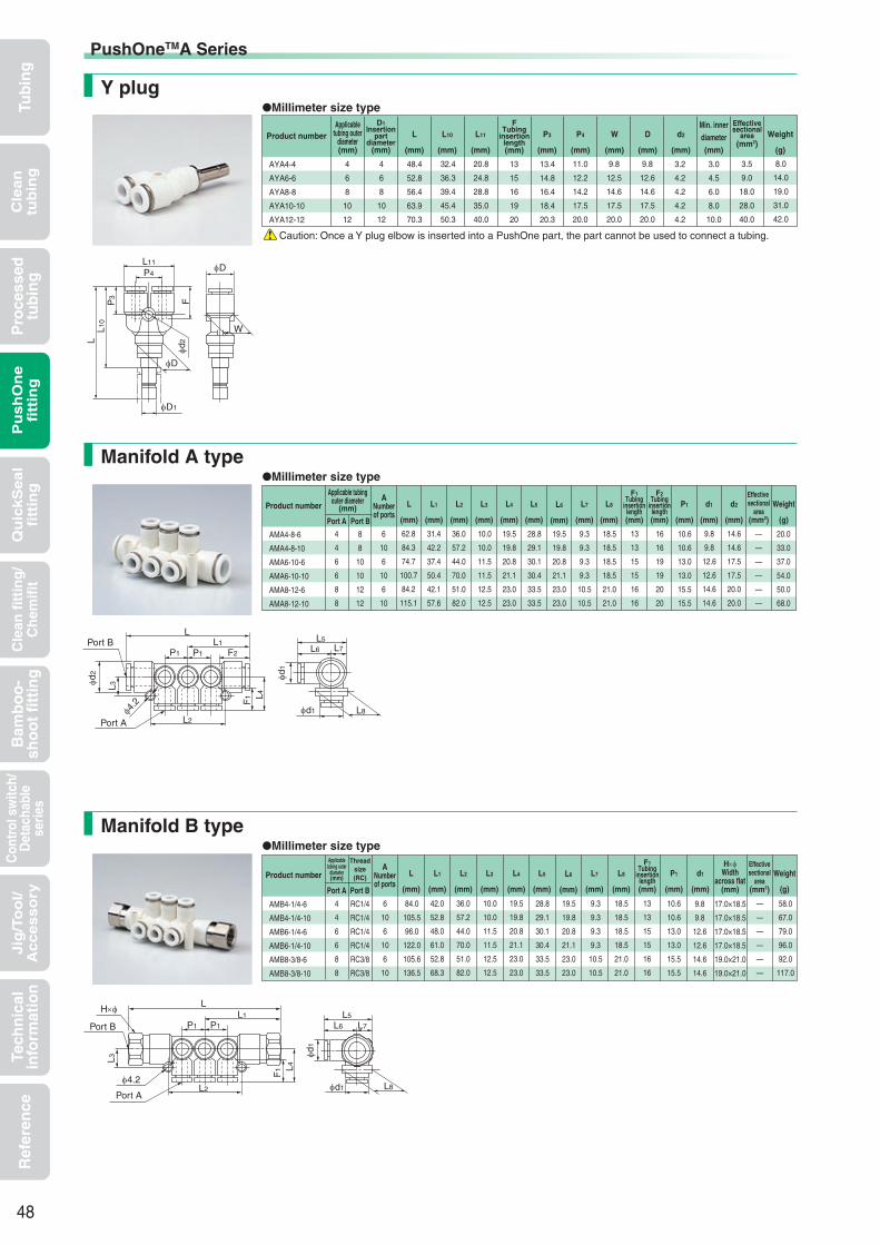
Tub
ing
Cle
an
tub
ing
Pu
sh
On
efi
ttin
gQ
uic
kS
ea
lfi
ttin
gB
amb
oo
-sh
oo
t fi
ttin
gC
ontr
ol s
witc
h/D
etac
habl
ese
ries
Cle
an f
itti
ng
/C
hem
ifit
Jig
/To
ol/
Accesso
ryR
efer
ence
Pro
cess
edtu
bin
gTe
chn
ical
info
rmat
ion
Millimeter size typeY plug
Millimeter size typeManifold A type
Millimeter size typeManifold B type
AMA4-8-6
AMA4-8-10
AMA6-10-6
AMA6-10-10
AMA8-12-6
AMA8-12-10
4
4
6
6
8
8
6
10
6
10
6
10
9.3
9.3
9.3
9.3
10.5
10.5
18.5
18.5
18.5
18.5
21.0
21.0
16
16
19
19
20
20
31.4
42.2
37.4
50.4
42.1
57.6
36.0
57.2
44.0
70.0
51.0
82.0
10.0
10.0
11.5
11.5
12.5
12.5
13
13
15
15
16
16
14.6
14.6
17.5
17.5
20.0
20.0
8
8
10
10
12
12
62.8
84.3
74.7
100.7
84.2
115.1
9.8
9.8
12.6
12.6
14.6
14.6
20.0
33.0
37.0
54.0
50.0
68.0
—
—
—
—
—
—
10.6
10.6
13.0
13.0
15.5
15.5
19.5
19.8
20.8
21.1
23.0
23.0
28.8
29.1
30.1
30.4
33.5
33.5
19.5
19.8
20.8
21.1
23.0
23.0
AYA4-4
AYA6-6
AYA8-8
AYA10-10
AYA12-12
4
6
8
10
12
48.4
52.8
56.4
63.9
70.3
13.4
14.8
16.4
18.4
20.3
13
15
16
19
20
3.0
4.5
6.0
8.0
10.0
8.0
14.0
19.0
31.0
42.0
4
6
8
10
12
3.2
4.2
4.2
4.2
4.2
32.4
36.3
39.4
45.4
50.3
20.8
24.8
28.8
35.0
40.0
11.0
12.2
14.2
17.5
20.0
9.8
12.5
14.6
17.5
20.0
9.8
12.6
14.6
17.5
20.0
3.5
9.0
18.0
28.0
40.0
Caution: Once a Y plug elbow is inserted into a PushOne part, the part cannot be used to connect a tubing.
AMB4-1/4-6
AMB4-1/4-10
AMB6-1/4-6
AMB6-1/4-10
AMB8-3/8-6
AMB8-3/8-10
4
4
6
6
8
8
6
10
6
10
6
10
28.8
29.1
30.1
30.4
33.5
33.5
9.3
9.3
9.3
9.3
10.5
10.5
18.5
18.5
18.5
18.5
21.0
21.0
9.8
9.8
12.6
12.6
14.6
14.6
42.0
52.8
48.0
61.0
52.8
68.3
36.0
57.2
44.0
70.0
51.0
82.0
10.0
10.0
11.5
11.5
12.5
12.5
13
13
15
15
16
16
19.5
19.8
20.8
21.1
23.0
23.0
RC1/4
RC1/4
RC1/4
RC1/4
RC3/8
RC3/8
84.0
105.5
96.0
122.0
105.6
136.5
19.5
19.8
20.8
21.1
23.0
23.0
10.6
10.6
13.0
13.0
15.5
15.5
58.0
67.0
79.0
96.0
92.0
117.0
—
—
—
—
—
—
17.0×18.5
17.0×18.5
17.0×18.5
17.0×18.5
19.0×21.0
19.0×21.0
Applicabletubing outer
diameter(mm)
D1Insertion
partdiameter
(mm)
FTubing
insertionlength(mm)
Weight
(g)
Effectivesectional
area(mm2)
Product number D
(mm)
W
(mm)
d2
(mm)
Min. innerdiameter(mm)
L
(mm)
L10
(mm)
L11
(mm)
P3
(mm)
P4
(mm)
Applicable tubingouter diameter
(mm)A
Numberof ports
F2Tubing
insertionlength(mm)
F1Tubing
insertionlength(mm)
Weight
(g)
Effective sectional
area(mm2)
Product number d2
(mm)
d1
(mm)
P1
(mm)
L
(mm)
L1
(mm)
L2
(mm)
L3
(mm)
L4
(mm)
L5
(mm)
L6
(mm)
L7
(mm)
L8
(mm)Port A Port B
Applicabletubing outer
diameter(mm)
Threadsize(RC)
ANumberof ports
F1Tubing
insertionlength(mm)
Weight
(g)
Effectivesectional
area(mm2)
Product number d1
(mm)
P1
(mm)
L
(mm)
L1
(mm)
L2
(mm)
L3
(mm)
L4
(mm)
L5
(mm)
L6
(mm)
L7
(mm)
L8
(mm)Port A Port B
H×φWidth
across flat(mm)
48
φD1
φd2L
L10
P3 F
P4
L11
φD
φD
W
φd1
L5
φd1
L6 L7
L8
LL1
F2P1P1
L2
F1 L4
φd2
L3φ4
.2
Port B
Port A
φd1
L5
φd1
L6 L7
L8
LL1
P1P1
L2
F1 L4
H×φ
L3
Port B
Port A
φ4.2
PushOneTMA Series

Tub
ing
Cle
an
tub
ing
Pu
sh
On
efi
ttin
gQ
uic
kS
ea
lfi
ttin
gB
amb
oo
-sh
oo
t fi
ttin
gC
ontr
ol s
witc
h/D
etac
habl
ese
ries
Cle
an f
itti
ng
/C
hem
ifit
Jig
/To
ol/
Accesso
ryR
efer
ence
Pro
cess
edtu
bin
gTe
chn
ical
info
rmat
ion
Millimeter size typeTubing cap
Millimeter size typeNipple
Millimeter size typeBlank plug
BC4
BC6
BC8
BC10
BC12
4
6
8
10
12
15.5
16.0
16.0
17.7
20.4
28.0
28.0
29.0
32.0
34.0
7.7
9.7
11.7
14.0
16.0
0.8
1.2
1.7
2.5
3.8
EN4
EN4-6
EN6
EN6-8
EN8
EN8-10
EN10
EN10-12
EN12
4
4
6
6
8
8
10
10
12
2.5
2.5
4.0
4.0
6.0
6.0
7.5
7.5
9.0
—
6
—
8
—
10
—
12
—
37.0
38.0
39.0
41.0
43.0
46.0
49.0
50.5
52.0
—
18.5
—
19.5
—
21.5
—
24.5
—
1.0
1.0
1.0
1.0
1.0
2.0
2.0
3.0
3.0
ACC4
ACC6
ACC8
ACC10
ACC12
4
6
8
10
12
13
15
16
19
20
9.8
12.6
14.6
17.5
20.0
15.0
16.9
17.9
21.7
22.6
2.0
3.0
4.0
6.0
8.0
D1Insertion part
diameter(mm)
D2Insertion part
diameter(mm)
Weight
(g)
Product number d1
(mm)
L
(mm)
L1
(mm)
D1Insertion part
diameter(mm)
Weight
(g)
Product number D
(mm)
L
(mm)
L1
(mm)
d1Applicable tubing
outer diameter(mm)
FTubing insertion
length(mm)
Weight
(g)
Product number L
(mm)
D1
(mm)
Caution:Material:POM(not flame-retardant resin)
Caution:Material:POM(not flame-retardant resin)
49
φD1
L
L1
φD
L
L
L1
φD2
φD1
φd1
φD1
φd1
F
L
φD1
φd1
PushOneTMA Series

Tub
ing
Cle
an
tub
ing
Pu
sh
On
efi
ttin
gQ
uic
kS
ea
lfi
ttin
gB
amb
oo
-sh
oo
t fi
ttin
gC
ontr
ol s
witc
h/D
etac
habl
ese
ries
Cle
an f
itti
ng
/C
hem
ifit
Jig
/To
ol/
Accesso
ryR
efer
ence
Pro
cess
edtu
bin
gTe
chn
ical
info
rmat
ion
Handling instructions
Operating fluid, working temperature range
Product number example
Cross-sectional structure diagram
Features
Related products and product introductionSpeed controller Off tool
PushOne connection of tubingThe tubes can be connected without using a jig or tools.
Electroless nickel platedPrevents degradation of surface and dissolution of copper ions into fluid.
Compact bodySuitable for narrow piping or compact design equipment.
Sealing-processed R threadSealing tape is not required.
PushOneTM fittings for general air pressure
Operating fluid Working temperature range
Air −20°C∼+80°C
PushOneTMA Series Mini Type
Pressure conditionMaximum working pressure:1.0MPaNegative pressure performance:
−99.975kPa
See “Combination List of Tubing and Fitting” on page 8.
Size comparison of mini types
Applicable tubingPolyurethane tubing Nylon tubing
ReferenceInstruction manual ·······P.170Effective sectional area ·· P.168Negative-pressure performance list ··········P.169
(*1) When the PushOne E series of the Mini type is used with a UE tubing, choose a metal body type including a connector and a hexagonal socket to maintain conductivity between the tubing and the fittings.
(*2) Combinatory use of PL, PN, TA or TP tubing and PushOne E series of the Mini type mixes general and clean type performances. When using them together in a clean environment, be aware of how this could lower the cleanliness level.
Antistatic tubing Polyolefin resin tubing Fluorocarbon resin tubing*2*2*1
A series A seriesMini type Tubing size : φ4
Thread size : M5
(Compared size)
PushOneTMSeries
AL 6 - R1/8 - M
ShapeApplicable tubing outer diameter
Thread size
Mini type
When the working conditions of tubes and fittings differ, use them under the lower specified conditions.
Do not bend the pipe sharply near the tubing insertion port of the fitting. Keep the tubing straight for twice as long as the tubing diameter from the insertion port.
Caution:
Caution:
See page 34 for the common handling instructions for fittings.
U2 U1 N2 N5 N1 UE PL PN TA TP
50
Body (PBT) Tubing seal (NBR)
Back ring (Brass electroless nickel plating or POM resin)
Except M5 thread
Lock ring (stainless)
Collar (electroless nickel plated brass)
Release sleeve (POM resin)
Tubing
O ring (NBR)
Adapter (electroless nickel plated brass)
Sealing processed (fluorocarbon resin coating)
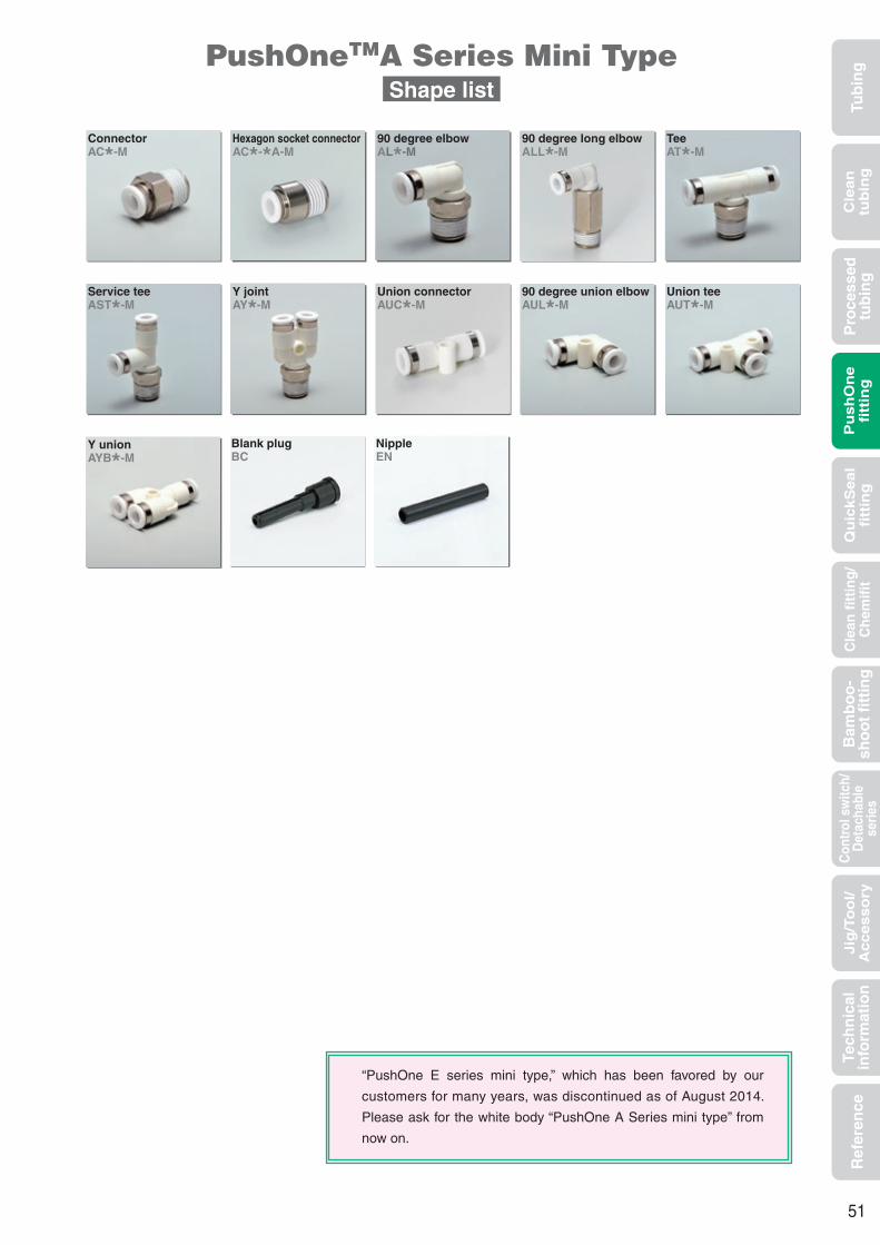
Tub
ing
Cle
an
tub
ing
Pu
sh
On
efi
ttin
gQ
uic
kS
ea
lfi
ttin
gB
amb
oo
-sh
oo
t fi
ttin
gC
ontr
ol s
witc
h/D
etac
habl
ese
ries
Cle
an f
itti
ng
/C
hem
ifit
Jig
/To
ol/
Accesso
ryR
efer
ence
Pro
cess
edtu
bin
gTe
chn
ical
info
rmat
ion
Blank plugBC
NippleEN
PushOneTMA Series Mini TypeShape list
ConnectorAC*-M
Hexagon socket connectorAC*-*A-M
90 degree elbowAL*-M
90 degree long elbowALL*-M
TeeAT*-M
Service teeAST*-M
Y jointAY*-M
Union connectorAUC*-M
90 degree union elbowAUL*-M
Union teeAUT*-M
Y unionAYB*-M
51
“PushOne E series mini type,” which has been favored by our
customers for many years, was discontinued as of August 2014.
Please ask for the white body “PushOne A Series mini type” from
now on.

Tub
ing
Cle
an
tub
ing
Pu
sh
On
efi
ttin
gQ
uic
kS
ea
lfi
ttin
gB
amb
oo
-sh
oo
t fi
ttin
gC
ontr
ol s
witc
h/D
etac
habl
ese
ries
Cle
an f
itti
ng
/C
hem
ifit
Jig
/To
ol/
Accesso
ryR
efer
ence
Pro
cess
edtu
bin
gTe
chn
ical
info
rmat
ion
AC3-M3-M
AC3-M5-M
AC4-M3-M
AC4-M5-M
AC4-R1/8-M
AC6-M5-M
AC6-R1/8-M
3
3
4
4
4
6
6
M3×0.5
M5×0.8
M3×0.5
M5×0.8
R1/8
M5×0.8
R1/8
14.9
15.9
15.9
15.9
15.7
17.0
18.5
3.0
3.5
3.0
3.5
7.3
3.5
7.3
11.0
11.0
11.5
11.5
11.5
12.5
12.5
5.5×6.0
7.0×7.7
8.0×8.8
8.0×8.8
10.0×11.0
10.0×11.0
10.0×11.0
1.5
2.0
1.5
2.5
2.5
2.5
4.0
1.3
3.1
2.9
3.1
6.1
4.1
6.3
2.0
2.5
2.0
3.5
4.0
4.5
9.0
Millimeter size typeHexagon socket connector
3
3
4
4
4
6
6
AC3-M3A-M
AC3-M5A-M
AC4-M3A-M
AC4-M5A-M
AC4-R1/8A-M
AC6-M5A-M
AC6-R1/8A-M
M3×0.5
M5×0.8
M3×0.5
M5×0.8
R1/8
M5×0.8
R1/8
14.9
15.9
15.9
15.9
15.7
17.0
18.5
3.0
3.5
3.0
3.5
7.3
3.5
7.3
11.0
11.0
11.5
11.5
11.5
12.5
12.5
1.5
2.0
1.5
2.5
2.5
2.5
4.0
1.5
2.0
1.5
2.5
2.5
2.5
4.0
1.2
2.9
2.5
2.8
5.8
3.6
5.7
5.6
6.8
8.0
8.0
10.0
9.8
10.0
2.0
2.5
2.0
3.5
4.0
4.5
9.0
Millimeter size type90 degree elbow
AL3-M3-M
AL3-M5-M
AL4-M3-M
AL4-M5-M
AL4-R1/8-M
AL6-M5-M
AL6-R1/8-M
3
3
4
4
4
6
6
M3×0.5
M5×0.8
M3×0.5
M5×0.8
R1/8
M5×0.8
R1/8
12.6
12.6
14.4
14.4
14.4
15.6
15.6
3.0
3.5
3.0
3.5
8.0
3.5
8.0
11.0
11.0
11.5
11.5
11.5
12.5
12.5
5.5×6.0
7.0×7.7
8.0×8.8
8.0×8.8
10.0×11.0
8.0×8.8
10.0×11.0
1.5
1.5
1.5
2.5
3.0
2.5
4.0
1.6
2.2
2.6
3.2
6.1
3.6
6.5
12.0
13.0
12.5
13.0
16.0
14.0
17.0
15.6
16.4
18.8
18.8
19.9
20.0
21.1
15.2
16.2
16.5
17.0
20.0
19.0
22.0
6.3
6.3
8.0
8.0
8.0
10.0
10.0
1.5
2.5
1.5
2.5
5.0
2.5
5.0
1.5
1.5
2.0
3.5
4.0
4.5
8.0
Millimeter size typeConnector
Applicabletubing outer
diameter(mm)
TThread size
(M,R)
FTubing insertion
length(mm)
H×φWidth
across flat(mm)
Weight
(g)
Effectivesectional
area(mm2)
Product numberd1
Min. innerdiameter
(mm)
L
(mm)
A
(mm)
Applicabletubing outer
diameter(mm)
TThread size
(M,R)
FTubing insertion
length(mm)
hWidth
across flat(mm)
Weight
(g)
Effectivesectional
area(mm2)
Product number D
(mm)
d1Min. innerdiameter
(mm)
L
(mm)
A
(mm)
Applicabletubing outer
diameter(mm)
TThread size
(M,R)
FTubing
insertionlength(mm)
Min. innerdiameter
(mm)
H×φWidth
across flat(mm)
Weight
(g)
Effectivesectional
area(mm2)
Product number D
(mm)
d1
(mm)
L1
(mm)
L2
(mm)
L3
(mm)
L4
(mm)
A
(mm)
52
L
φd1
T F
A H×φ
A
with gasket
M thread T
φd1
φd1
T
AL
F
A
with gasket
M thread T
φd1
h
φDφD
L3
φd1
H×φ
L1F
T
L4
L2
A
Tφd1
A
M thread
with gasket
PushOneTMA Series Mini Type

Tub
ing
Cle
an
tub
ing
Pu
sh
On
efi
ttin
gQ
uic
kS
ea
lfi
ttin
gB
amb
oo
-sh
oo
t fi
ttin
gC
ontr
ol s
witc
h/D
etac
habl
ese
ries
Cle
an f
itti
ng
/C
hem
ifit
Jig
/To
ol/
Accesso
ryR
efer
ence
Pro
cess
edtu
bin
gTe
chn
ical
info
rmat
ion
Millimeter size type90 degree long elbow
ALL3-M3-M
ALL3-M5-M
ALL4-M3-M
ALL4-M5-M
ALL4-R1/8-M
ALL6-M5-M
ALL6-R1/8-M
3
3
4
4
4
6
6
M3×0.5
M5×0.8
M3×0.5
M5×0.8
R1/8
M5×0.8
R1/8
12.6
12.6
14.4
14.4
14.4
15.6
15.6
3.0
3.5
3.0
3.5
8.0
3.5
8.0
11.0
11.0
11.5
11.5
11.5
12.5
12.5
5.5×6.0
7.0×7.7
8.0×8.8
8.0×8.8
10.0×11.0
8.0×8.8
10.0×11.0
1.5
1.5
1.5
2.5
3.0
2.5
4.0
3.4
4.5
6.8
7.4
12.7
7.8
13.1
20.0
21.0
24.5
25.0
28.0
26.0
29.0
15.6
16.4
18.8
18.8
19.9
20.0
21.1
23.2
24.2
28.5
29.0
32.0
31.0
34.0
6.3
6.3
8.0
8.0
8.0
10.0
10.0
1.5
2.5
1.5
2.5
5.0
2.5
5.0
1.5
1.5
2.0
3.5
4.0
4.5
8.0
Millimeter size typeTee
AT3-M3-M
AT3-M5-M
AT4-M3-M
AT4-M5-M
AT4-R1/8-M
AT6-M5-M
AT6-R1/8-M
3
3
4
4
4
6
6
M3×0.5
M5×0.8
M3×0.5
M5×0.8
R1/8
M5×0.8
R1/8
12.6
12.6
14.9
14.9
14.9
16.1
16.1
3.0
3.5
3.0
3.5
8.0
3.5
8.0
11.0
11.0
11.5
11.5
11.5
12.5
12.5
5.5×6.0
7.0×7.7
8.0×8.8
8.0×8.8
10.0×11.0
8.0×8.8
10.0×11.0
1.5
1.5
1.5
2.5
3.0
2.5
4.0
2.1
2.7
3.5
4.1
7.0
4.8
7.7
12.0
13.0
12.5
13.0
16.0
14.0
17.0
15.2
16.2
16.5
17.0
20.0
19.0
22.0
25.1
25.1
29.8
29.8
29.8
32.1
32.1
6.3
6.3
8.0
8.0
8.0
10.0
10.0
1.5
2.5
1.5
2.5
5.0
2.5
5.0
1.5
1.5
2.0
3.5
4.0
4.5
8.0
Millimeter size typeService tee
AST3-M3-M
AST3-M5-M
AST4-M3-M
AST4-M5-M
AST4-R1/8-M
AST6-M5-M
AST6-R1/8-M
3
3
4
4
4
6
6
M3×0.5
M5×0.8
M3×0.5
M5×0.8
R1/8
M5×0.8
R1/8
12.6
12.6
14.9
14.9
14.9
16.1
16.1
3.0
3.5
3.0
3.5
8.0
3.5
8.0
11.0
11.0
11.5
11.5
11.5
12.5
12.5
5.5×6.0
7.0×7.7
8.0×8.8
8.0×8.8
10.0×11.0
8.0×8.8
10.0×11.0
1.5
1.5
1.5
2.5
3.0
2.5
4.0
2.1
2.7
3.5
4.1
7.0
4.8
7.7
12.0
13.0
12.5
13.0
16.0
14.0
17.0
12.6
12.6
14.9
14.9
14.9
16.1
16.1
24.6
25.6
27.4
27.9
30.9
30.1
33.1
6.3
6.3
8.0
8.0
8.0
10.0
10.0
1.5
2.5
1.5
2.5
5.0
2.5
5.0
15.7
16.4
19.3
19.3
20.4
21.1
21.6
1.5
1.5
2.0
3.5
4.0
4.5
8.0
Applicabletubing outer
diameter(mm)
TThread size
(M,R)
FTubing
insertionlength(mm)
Min. innerdiameter
(mm)
H×φWidth
across flat(mm)
Weight
(g)
Effectivesectional
area(mm2)
Product number D
(mm)
d1
(mm)
L1
(mm)
L2
(mm)
L3
(mm)
L4
(mm)
A
(mm)
Applicabletubing outer
diameter(mm)
TThread size
(M,R)
FTubing
insertionlength(mm)
Min. innerdiameter
(mm)
H×φWidth
across flat(mm)
Weight
(g)
Effectivesectional
area(mm2)
Product number D
(mm)
d1
(mm)
L1
(mm)
L2
(mm)
L4
(mm)
L5
(mm)
A
(mm)
Applicabletubing outer
diameter(mm)
TThread size
(M,R)
FTubing
insertionlength(mm)
H×φWidthacross
flat(mm)
Weight
(g)
Effectivesectional
area(mm2)
Product number D
(mm)
d1
(mm)
Min. innerdiameter
(mm)
L1
(mm)
L2
(mm)
L6
(mm)
L7
(mm)
L8
(mm)
A
(mm)
53
φD
L3
φd1
H×φ
L1
F
T
L4
L2
A
Tφd1
A
M thread
with gasket
φD
L5
L4
φd1
H×φ
L1
F
T
L2A
T
φd1
A
M thread
with gasket
φD
L7
H×φ
L2 L1
A F
L6
φd1
T
L8
A
with gasket
M threadT
φd1
PushOneTMA Series Mini Type
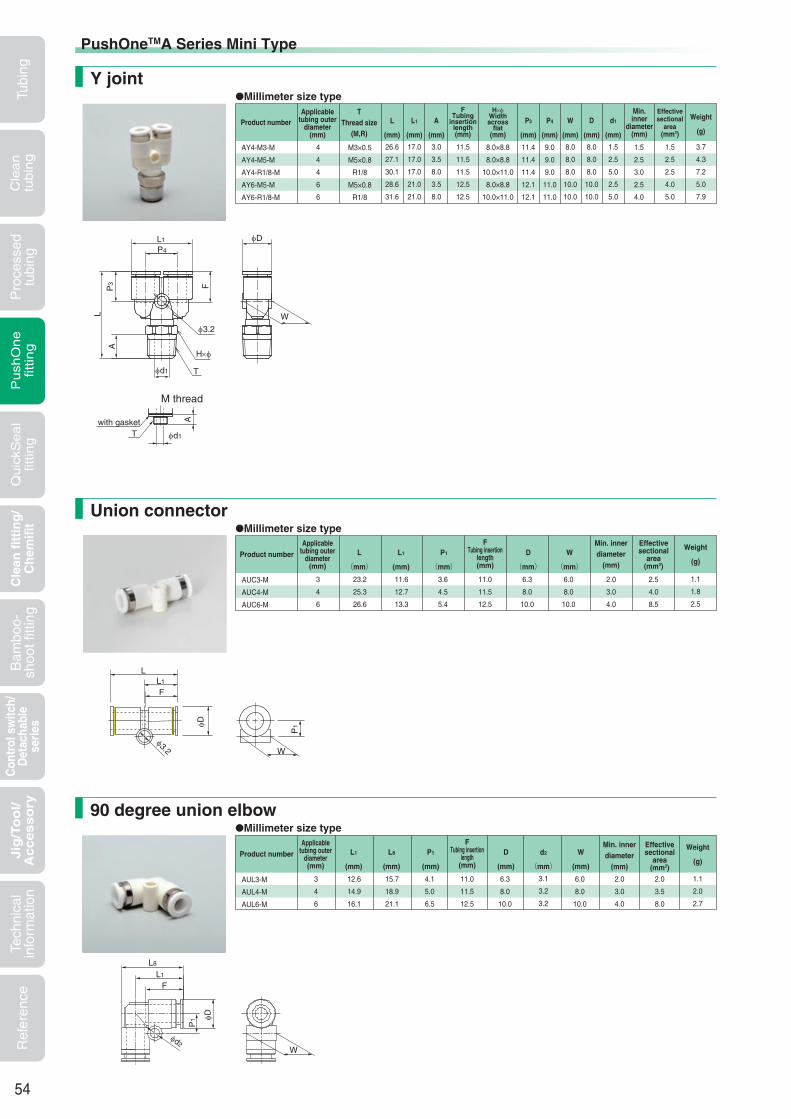
Tubi
ngC
lea
ntu
bin
gP
ush
On
efit
ting
Qu
ickS
ea
lfit
ting
Bam
boo-
shoo
t fitt
ing
Con
trol
sw
itch/
Det
acha
ble
serie
sC
lean
fit
tin
g/
Ch
emif
itJig
/To
ol/
Accesso
ryR
efer
ence
Pro
cess
edtu
bing
Tech
nica
lin
form
atio
n
Applicabletubing outer
diameter(mm)
Effectivesectional
area(mm2)
Product numberMin. innerdiameter
(mm)
L
(mm)P1
(mm)
FTubing insertion
length(mm)
Weight
(g)
AUC3-M
AUC4-M
AUC6-M
3
4
6
23.2
25.3
26.6
3.6
4.5
5.4
11.0
11.5
12.5
2.0
3.0
4.0
1.1
1.8
2.5
L1
(mm)
11.6
12.7
13.3
D
(mm)6.3
8.0
10.0
W
(mm)6.0
8.0
10.0
2.5
4.0
8.5
AY4-M3-M
AY4-M5-M
AY4-R1/8-M
AY6-M5-M
AY6-R1/8-M
4
4
4
6
6
M3×0.5
M5×0.8
R1/8
M5×0.8
R1/8
26.6
27.1
30.1
28.6
31.6
1.5
2.5
3.0
2.5
4.0
3.7
4.3
7.2
5.0
7.9
17.0
17.0
17.0
21.0
21.0
3.0
3.5
8.0
3.5
8.0
Applicabletubing outer
diameter(mm)
TThread size
(M,R)
Effectivesectional
area(mm2)
Product numberMin.inner
diameter(mm)
Weight
(g)L1
(mm)
A
(mm)
L
(mm)
8.0
8.0
8.0
10.0
10.0
11.4
11.4
11.4
12.1
12.1
8.0
8.0
8.0
10.0
10.0
1.5
2.5
5.0
2.5
5.0
D
(mm)
d1
(mm)
P3
(mm)
W
(mm)
9.0
9.0
9.0
11.0
11.0
P4
(mm)
11.5
11.5
11.5
12.5
12.5
8.0×8.8
8.0×8.8
10.0×11.0
8.0×8.8
10.0×11.0
H×φWidthacross
flat(mm)
FTubing
insertionlength(mm)
1.5
2.5
2.5
4.0
5.0
Millimeter size typeUnion connector
Millimeter size type90 degree union elbow
Millimeter size typeY joint
Applicabletubing outer
diameter(mm)
Effectivesectional
area(mm2)
Product numberMin. innerdiameter
(mm)
L1
(mm)
P1
(mm)
FTubing insertion
length(mm)
Weight
(g)
AUL3-M
AUL4-M
AUL6-M
3
4
6
12.6
14.9
16.1
4.1
5.0
6.5
11.0
11.5
12.5
2.0
3.0
4.0
1.1
2.0
2.7
L8
(mm)
15.7
18.9
21.1
D
(mm)
6.3
8.0
10.0
W
(mm)
6.0
8.0
10.0
2.0
3.5
8.0
3.1
3.2
3.2
d2
(mm)
54
PushOneTMA Series Mini Type
W
φD
φ3.2
LL1
F
P1
φ3.2
W
φd1 T
A
φD
F
H×φ
P3
L
T φd1
A
M thread
with gasket
P4
L1
W
φD
φd2
P1
L8
L1
F

Tubi
ngC
lea
ntu
bin
gP
ush
On
efit
ting
Qu
ickS
ea
lfit
ting
Bam
boo-
shoo
t fitt
ing
Con
trol
sw
itch/
Det
acha
ble
serie
s
Cle
an f
itti
ng
/C
hem
ifit
Jig
/To
ol/
Accesso
ryR
efer
ence
Pro
cess
edtu
bing
Tech
nica
lin
form
atio
n
Millimeter size typeUnion tee
Millimeter size typeY union
AYB3-M
AYB4-M
AYB6-M
3
4
6
25.7
28.8
31.1
7.0
9.0
11.0
11.0
11.5
12.5
2.0
3.0
4.0
1.8
3.1
4.0
6.3
8.0
10.0
6.0
8.0
10.0
13.3
17.0
21.0
10.9
11.4
12.1
2.0
3.2
3.2
2.0
2.0
8.0
NippleBlank plug
See the PushOne E series (P.71) for the product number and part sizes.
See the PushOne E series (P.71) for the product number and part sizes.
Applicabletubing outer
diameter(mm)
FTubing
insertionlength(mm)
Weight
(g)
Effectivesectional
area(mm2)
Product number W
(mm)
P3
(mm)
D
(mm)
P4
(mm)
d2
(mm)
Min. innerdiameter
(mm)
L
(mm)
L11
(mm)
Applicabletubing outer
diameter(mm)
Effectivesectional
area(mm2)
Product numberMin. innerdiameter
(mm)
L1
(mm)
P2
(mm)
FTubing
insertionlength(mm)
Weight
(g)
AUT3-M
AUT4-M
AUT6-M
3
4
6
12.6
14.9
16.1
8.2
10.0
13.0
d2
(mm)
3.2
3.2
3.2
11.0
11.5
12.5
2.0
3.0
4.0
1.7
3.0
3.9
L5
(mm)
25.1
29.8
32.1
D
(mm)
6.3
8.0
10.0
W
(mm)
6.0
8.0
10.0
L6
(mm)
12.6
14.9
16.1
P1
(mm)
4.1
5.0
6.5
L8
(mm)
15.7
18.9
21.1
2.0
3.5
8.0
55
PushOneTMA Series Mini Type
Wφd2
φD
L
P3
FF
L11
P4
φD
φd2
F
P1
L1
L5
L6
P2
L8
W

Tub
ing
Cle
an
tub
ing
Pu
sh
On
efi
ttin
gQ
uic
kS
ea
lfi
ttin
gB
amb
oo
-sh
oo
t fi
ttin
gC
ontr
ol s
witc
h/D
etac
habl
ese
ries
Cle
an f
itti
ng
/C
hem
ifit
Jig
/To
ol/
Accesso
ryR
efer
ence
Pro
cess
edtu
bin
gTe
chn
ical
info
rmat
ion
The inch size type has a white release sleeve.
Distinction of millimeter/inch sizes
Features
PushOneTME SeriesPushOneTM fittings for general air pressure (flame-resistant)
Operating fluid Working temperature range
See “Combination List of Tubing and Fitting” on page 8.
*2*2*1
Inch Millimeter
PushOneTMSeries
Handling instructions
Operating fluid, working temperature range
Pressure condition
Applicable tubing
Product number example
Cross-sectional structure diagram
Related products and product introduction
Reference
PushOne connection of tubingThe tubes can be connected without using a jig or tools.
Electroless nickel platedPrevents degradation of surface and dissolution of copper ions in fluid.
Flame-resistant resin (compliant with V-0 of UL94 standard)Made of flame-resistant resin PBT. High self-extinguishing performance is compliant with V-0 of UL94 standard. Usable under an environment with spatters.
Sealing-processed R threadSealing tape is not required.
EL 6 - PT1/8
ShapeApplicable tubing outer diameter
Thread size
Air
Water 0°C∼+40°C
−20°C∼+80°C
Maximum working pressure:1.0MPaNegative pressure performance:
−99.975kPa
When the working conditions of tubes and fittings differ, use them under the lower specified conditions.
When water is used as the operating fluid, confirm that there is no water leakage damage to equipment and instruments due to construction failure.
When water is used as the operating fluid, do not allow it to freeze.
Do not bend the pipe sharply near the tubing insertion port of the fitting. Keep the tubing straight for twice as long as the tubing diameter from the insertion port.
Caution:
Caution:
Caution:
Caution:
See page 34 for the common handling instructions for fittings.
Instruction manual ·······P.170UL-94 standard flame test ···························P.195Effective sectional area ···P.168Negative-pressure performance list ··········P.169
Polyurethane tubing Nylon tubing Flame-resistant tubing Antistatic tubing Polyolefin resin tubing Fluorocarbon resin tubing
U2 U1 U5 N2 N5 N1 FS FW FWU FUK UE PL PN TA TP
(*1) When the PushOne E series is used with a UE tubing, choose a metal body type including a connector anda hexagonal socket to maintain conductivity between the tubing and the fittings.
(*2) Combinatory use of PL, PN, TA or TP tubing and PushOne E series mixes general and clean type performances. When using them together in a clean environment, be aware of how this could lower the cleanliness level.
Speed controller Ball valve Miniature valve Valve built-in connector Q.D.C 101 series Spatter cap
56
Body(flame-resistant PBT resin) Tubing seal (special NBR)
Back ring (millimeter size: electroless nickel plated zinc alloy) (inch size: POM resin)
The inch size type is not plated.
Lock ring (stainless)
Release sleeve (flame-resistant PBT resin)
Tubing
Collar (millimeter size: electroless nickel plated zinc alloy) (inch size: brass)
O ring (special NBR)
Adapter (millimeter size: electroless nickel plated brass) (inch size: brass)
Sealing processed (fluorocarbon resin coating)
Except M5 thread

Tub
ing
Cle
an
tub
ing
Pu
sh
On
efi
ttin
gQ
uic
kS
ea
lfi
ttin
gB
amb
oo
-sh
oo
t fi
ttin
gC
ontr
ol s
witc
h/D
etac
habl
ese
ries
Cle
an f
itti
ng
/C
hem
ifit
Jig
/To
ol/
Accesso
ryR
efer
ence
Pro
cess
edtu
bin
gTe
chn
ical
info
rmat
ion
PushOneTME SeriesShape list
ConnectorEC
Hexagon socket connectorEC*-*A
Internal connectorEFC
90 degree elbowEL
90 degree internal elbowEFL
90 degree long elbowELL
45 degree elbowE45L
Universal elbowELB
90 degree branch elbowELY
Universal branch elbowELYB
Double universal elbowELWB
Triple universal elbowELTB
TeeET
Service teeEST
Y jointEY
Union connectorEUC
90 degree union elbowEUL
90 degree branch union elbowEULY
Union teeEUT
Y unionEYB
Double Y unionEUWY
Panel touch connectorEPC
Internal panel touch connectorEPFC
90 degree panel touch elbowEPL
ReducerER
Adapter elbowEAL
Y plugEYA
Manifold A typeEMA
Manifold B typeEMB
Tubing capECC
Blank plugBC
NippleEN
57

Connector
Millimeter size typeHexagon socket connector
EC4-M5A
EC4-PT1/8A
EC6-M5A
EC6-PT1/8A
EC6-PT1/4A
EC8-PT1/8A
EC8-PT1/4A
EC10-PT1/4A
EC10-PT3/8A
4
4
6
6
6
8
8
10
10
19.4
19.4
24.2
21.2
24.2
26.2
25.2
28.1
29.1
4.0
8.0
4.0
8.0
11.0
8.0
11.0
11.0
12.0
13
13
15
15
15
16
16
19
19
2.0
2.5
4.0
4.0
4.0
5.0
5.0
6.0
6.0
9.8
9.8
11.8
11.8
13.8
13.8
13.8
16.8
16.8
2.0
2.5
2.0
4.0
4.0
5.0
5.0
6.0
6.0
M5×0.8
R1/8
M5×0.8
R1/8
R1/4
R1/8
R1/4
R1/4
R3/8
5.0
7.0
18.0
8.0
17.0
12.0
15.0
19.0
28.0
—
—
—
—
—
—
—
—
—
Applicabletubing outer
diameter(mm)
TThread size
(M,R)
FTubing insertion
length(mm)
hWidth
across flat(mm)
Weight
(g)
Effectivesectional
area(mm2)
Product number D
(mm)
d1
(mm)
L
(mm)
A
(mm)
Tub
ing
Cle
an
tub
ing
Pu
sh
On
efi
ttin
gQ
uic
kS
ea
lfi
ttin
gB
amb
oo
-sh
oo
t fi
ttin
gC
ontr
ol s
witc
h/D
etac
habl
ese
ries
Cle
an f
itti
ng
/C
hem
ifit
Jig
/To
ol/
Accesso
ryR
efer
ence
Pro
cess
edtu
bin
gTe
chn
ical
info
rmat
ion
58
FT
T
AL
F
h
AL
φDφD
φd1
φ8 φd1
M5:φ8
,M6:φ9
M thread
Inch size type
Millimeter size type
φd1
A
with gasket
T
F
φd1
T
LA H×φ
h
PushOneTME Series
Applicabletubing outer
diameter(mm)
TThread size
(M,R)
FTubing insertion
length(mm)
H×φWidth across flat
(mm)
Weight
(g)
Effectivesectional
area(mm2)
Product number d1
(mm)
A
(mm)
EC4-M5
EC4-PT1/8
EC4-PT1/4
EC6-M5
EC6-M6
EC6-PT1/8
EC6-PT1/4
EC6-PT3/8
EC8-PT1/8
EC8-PT1/4
EC8-PT3/8
EC10-PT1/8
EC10-PT1/4
EC10-PT3/8
EC10-PT1/2
EC12-PT1/4
EC12-PT3/8
EC12-PT1/2
EC16-PT3/8
EC16-PT1/2
4
4
4
6
6
6
6
6
8
8
8
10
10
10
10
12
12
12
16
16
M5×0.8
R1/8
R1/4
M5×0.8
M6×1.0
R1/8
R1/4
R3/8
R1/8
R1/4
R3/8
R1/8
R1/4
R3/8
R1/2
R1/4
R3/8
R1/2
R3/8
R1/2
22.4
19.4
22.4
24.2
25.2
21.2
24.2
25.2
26.2
25.2
26.2
30.1
28.1
29.1
32.1
34.0
30.0
33.0
41.6
43.6
4.0
8.0
11.0
4.0
5.0
8.0
11.0
12.0
8.0
11.0
12.0
8.0
11.0
12.0
15.0
11.0
12.0
15.0
12.0
15.0
13
13
13
15
15
15
15
15
16
16
16
19
19
19
19
20
20
20
27
27
10.0×11.0
10.0×11.0
14.0×15.4
12.0×13.0
12.0×13.0
12.0×13.0
14.0×15.4
17.0×18.5
14.0×15.4
14.0×15.4
17.0×18.5
17.0×18.5
17.0×18.5
17.0×18.5
22.0×24.5
19.0×21.0
19.0×21.0
22.0×24.5
24.0×26.5
24.0×26.5
2.0
2.5
2.5
2.0
3.0
4.0
4.0
4.0
5.0
6.0
6.0
5.0
8.0
8.0
8.0
8.0
10.0
10.0
10.0
12.0
6.0
7.0
17.0
9.0
10.0
9.0
18.0
32.0
14.0
16.0
29.0
24.0
21.0
29.0
61.0
32.0
31.0
58.0
68.0
83.0
L
(mm)
3.0
4.0
4.0
3.5
4.5
10.5
10.5
10.5
20.0
25.0
26.0
25.0
40.0
40.0
40.0
45.0
50.0
50.0
77.0
110.5
EC1/4-M5
EC1/4-PT1/8
EC1/4-PT1/4
EC1/4-PT3/8
EC5/16-PT1/8
EC5/16-PT1/4
EC5/16-PT3/8
EC3/8-PT1/8
EC3/8-PT1/4
EC3/8-PT3/8
EC3/8-PT1/2
EC1/2-PT1/4
EC1/2-PT3/8
EC1/2-PT1/2
1/4
1/4
1/4
1/4
5/16
5/16
5/16
3/8
3/8
3/8
3/8
1/2
1/2
1/2
M5×0.8
R1/8
R1/4
R3/8
R1/8
R1/4
R3/8
R1/8
R1/4
R3/8
R1/2
R1/4
R3/8
R1/2
24.4
21.4
24.4
25.4
25.9
24.9
25.9
29.7
27.7
28.7
31.7
34.0
30.0
33.0
4.0
8.0
11.0
12.0
8.0
11.0
12.0
8.0
11.0
12.0
15.0
11.0
12.0
15.0
15
15
15
15
16
16
16
19
19
19
19
21
21
21
12.0×13.0
12.0×13.0
14.0×15.4
17.0×18.5
14.0×15.4
14.0×15.4
17.0×18.5
17.0×18.5
17.0×18.5
17.0×18.5
22.0×24.5
19.0×21.0
19.0×21.0
22.0×24.5
4.0
4.0
4.0
4.0
5.0
6.0
6.0
—
—
—
—
—
—
—
2.0
4.0
4.0
4.0
5.0
6.0
6.0
5.0
8.0
8.0
8.0
8.0
10.0
10.0
9.0
9.0
18.0
32.0
14.0
16.0
29.0
24.0
21.0
29.0
61.0
32.0
31.0
58.0
Applicabletubing outer
diameter(inch)
TThread size
(M,R)
FTubing insertion
length(mm)
H×φWidth across flat
(mm)
hWidth
across flat(mm)
Weight
(g)
Effectivesectional
area(mm2)
Product number d1
(mm)
L
(mm)
A
(mm)
3.5
12.0
12.0
12.0
20.0
25.0
26.0
20.0
35.0
35.0
35.0
48.0
66.5
66.5
F
φd1
T
LA H×φ
Millimeter size type
Inch size type
*Made to order
*
The inch size type is not plated.

Inch size type
EFC4-PT1/8
EFC6-PT1/8
EFC6-PT1/4
EFC8-PT1/4
EFC8-PT3/8
EFC10-PT1/4
EFC10-PT3/8
EFC10-PT1/2
EFC12-PT1/4
EFC12-PT3/8
EFC12-PT1/2
4
6
6
8
8
10
10
10
12
12
12
RC1/8
RC1/8
RC1/4
RC1/4
RC3/8
RC1/4
RC3/8
RC1/2
RC1/4
RC3/8
RC1/2
23.9
24.8
29.3
30.9
31.4
33.9
34.4
38.4
34.8
35.3
39.3
8.7
8.7
13.0
13.0
13.5
13.0
13.5
17.5
13.0
13.5
17.5
13
15
15
16
16
19
19
19
20
20
20
14.0×15.4
14.0×15.4
17.0×18.5
17.0×18.5
22.0×24.5
17.0×18.5
22.0×24.5
24.0×26.5
19.0×21.0
22.0×24.5
24.0×26.5
10.0
12.0
12.0
13.9
13.9
16.9
16.9
16.9
19.0
19.0
19.0
3.0
5.0
5.0
7.0
7.0
9.0
9.0
9.0
10.0
11.0
11.0
16.0
17.0
26.0
28.0
45.0
34.0
50.0
56.0
43.0
50.0
58.0
4.0
10.5
10.5
25.0
26.0
40.0
40.0
40.0
45.0
50.0
50.0
EFC1/4-PT1/8
EFC1/4-PT1/4
EFC5/16-PT1/4
EFC5/16-PT3/8
EFC3/8-PT1/4
EFC3/8-PT3/8
EFC3/8-PT1/2
EFC1/2-PT1/4
EFC1/2-PT3/8
EFC1/2-PT1/2
1/4
1/4
5/16
5/16
3/8
3/8
3/8
1/2
1/2
1/2
RC1/8
RC1/4
RC1/4
RC3/8
RC1/4
RC3/8
RC1/2
RC1/4
RC3/8
RC1/2
25.0
29.5
30.6
31.1
33.5
34.0
38.0
35.3
35.3
39.3
8.7
13.0
13.0
13.5
13.0
13.5
17.5
13.0
13.5
17.5
15
15
16
16
19
19
19
21
21
21
14.0×15.4
17.0×18.5
17.0×18.5
22.0×24.5
17.0×18.5
22.0×24.5
24.0×26.5
22.0×24.5
22.0×24.5
24.0×26.5
12.0
12.0
13.9
13.9
16.9
16.9
16.9
20.0
20.0
20.0
5.0
5.0
7.0
7.0
9.0
9.0
9.0
10.0
11.0
11.0
17.0
26.0
28.0
45.0
34.0
50.0
56.0
43.0
50.0
58.0
12.0
12.0
25.0
26.0
35.0
35.0
35.0
48.0
66.5
66.5
Millimeter size typeInternal connector
Inch size type
Millimeter size type90 degree elbow
EL1/4-M5
EL1/4-PT1/8
EL1/4-PT1/4
EL1/4-PT3/8
EL5/16-PT1/8
EL5/16-PT1/4
EL5/16-PT3/8
EL3/8-PT1/8
EL3/8-PT1/4
EL3/8-PT3/8
EL3/8-PT1/2
EL1/2-PT1/4
EL1/2-PT3/8
EL1/2-PT1/2
1/4
1/4
1/4
1/4
5/16
5/16
5/16
3/8
3/8
3/8
3/8
1/2
1/2
1/2
M5×0.8
R1/8
R1/4
R3/8
R1/8
R1/4
R3/8
R1/8
R1/4
R3/8
R1/2
R1/4
R3/8
R1/2
18.1
18.1
18.1
18.1
20.6
20.6
20.6
24.4
24.4
24.4
24.4
26.5
26.5
26.5
4.0
8.0
11.0
12.0
8.0
11.0
12.0
8.0
11.0
12.0
15.0
11.0
12.0
15.0
15
15
15
15
16
16
16
19
19
19
19
21
21
21
12.0×13.0
12.0×13.0
14.0×15.4
17.0×18.5
14.0×15.4
14.0×15.4
17.0×18.5
17.0×18.5
17.0×18.5
17.0×18.5
22.0×24.5
19.0×21.0
19.0×21.0
22.0×24.5
13.0
13.0
13.0
13.0
15.0
15.0
15.0
18.0
18.0
18.0
18.0
21.5
21.5
21.5
2.0
5.0
5.0
5.0
5.0
7.0
7.0
5.0
7.0
9.0
9.0
7.0
9.0
10.0
10.0
18.0
18.0
26.0
15.0
20.0
28.0
22.0
27.0
33.0
52.0
34.0
39.0
56.0
22.7
25.2
29.2
30.2
26.2
30.2
31.2
29.2
33.2
34.2
38.2
35.7
36.7
40.7
24.6
24.6
25.8
27.4
28.3
28.3
29.9
33.7
33.7
33.7
36.7
37.0
37.0
38.7
29.2
31.7
35.7
36.7
33.7
37.7
38.7
38.2
42.2
43.2
47.2
46.5
47.5
51.5
2.0
5.0
7.0
9.0
5.0
7.0
9.0
5.0
7.0
9.0
12.0
7.0
9.0
12.0
3.0
13.0
13.0
13.0
18.5
23.0
23.0
19.0
30.0
32.0
32.0
37.0
53.0
55.5
The inch size type is not plated.
The inch size type is not plated.
Applicabletubing outer
diameter(mm)
TThread size
(RC)
FTubing insertion
length(mm)
Min. innerdiameter
(mm)
H×φWidth across flat
(mm)
Weight
(g)
Effectivesectional
area(mm2)
Product number D
(mm)
L
(mm)
A
(mm)
Applicabletubing outer
diameter(inch)
TThread size
(RC)
FTubing insertion
length(mm)
Min. innerdiameter
(mm)
H×φφWidth across flat
(mm)
Weight
(g)
Effectivesectional
area(mm2)
Product number D
(mm)
L
(mm)
A
(mm)
Applicabletubing outer
diameter(inch)
TThread
size(M,R)
FTubing
insertionlength(mm)
Min. innerdiameter(mm)
H×φWidth across flat
(mm)
Weight
(g)
Effectivesectional
area(mm2)
Product number D
(mm)
d1
(mm)
L1
(mm)
L2
(mm)
L3
(mm)
L4
(mm)
A
(mm)
Tub
ing
Cle
an
tub
ing
Pu
sh
On
efi
ttin
gQ
uic
kS
ea
lfi
ttin
gB
amb
oo
-sh
oo
t fi
ttin
gC
ontr
ol s
witc
h/D
etac
habl
ese
ries
Cle
an f
itti
ng
/C
hem
ifit
Jig
/To
ol/
Accesso
ryR
efer
ence
Pro
cess
edtu
bin
gTe
chn
ical
info
rmat
ion
M thread
φD
L3
L1
F
L4L2
φd1 T
H×φA
φd1
M5:φ8,M6:φ9
A
with gasketT
φD
FA
LH×φ
T
PushOneTME Series
EL4-M5-Z2
EL4-PT1/8-Z2
EL4-PT1/4-Z2
EL6-M5-Z2
EL6-M6
EL6-PT1/8-Z2
EL6-PT1/4-Z2
EL6-PT3/8-Z2
EL8-PT1/8-Z2
EL8-PT1/4-Z2
EL8-PT3/8-Z2
EL10-PT1/8-Z2
EL10-PT1/4-Z2
EL10-PT3/8-Z2
EL10-PT1/2-Z2
EL12-PT1/4-Z2
EL12-PT3/8-Z2
EL12-PT1/2-Z2
EL16-PT3/8
EL16-PT1/2
4
4
4
6
6
6
6
6
8
8
8
10
10
10
10
12
12
12
16
16
M5×0.8
R1/8
R1/4
M5×0.8
M6×1.0
R1/8
R1/4
R3/8
R1/8
R1/4
R3/8
R1/8
R1/4
R3/8
R1/2
R1/4
R3/8
R1/2
R3/8
R1/2
17.2
17.2
17.2
18.5
18.5
18.5
18.5
18.5
20.7
20.7
20.7
24.7
24.7
24.7
24.7
26.3
26.3
26.3
34.9
34.9
4.0
8.0
12.0
4.0
5.0
8.0
12.0
12.0
8.0
12.0
12.0
8.0
12.0
12.0
16.0
12.0
12.0
16.0
12.0
15.0
13
13
13
15
15
15
15
15
16
16
16
19
19
19
19
20
20
20
27
27
10.0×11.0
10.0×11.0
14.0×15.4
12.0×13.0
12.0×13.0
12.0×13.0
14.0×15.4
17.0×18.5
14.0×15.4
14.0×15.4
17.0×18.5
17.0×18.5
17.0×18.5
17.0×18.5
22.0×24.5
19.0×21.0
19.0×21.0
22.0×24.5
24.0×27.0
24.0×27.0
9.8
9.8
9.8
12.6
12.6
12.6
12.6
12.6
14.6
14.6
14.6
17.5
17.5
17.5
17.5
20.0
20.0
20.0
28.0
28.0
2.0
3.0
3.0
2.0
3.0
5.0
5.0
5.0
5.0
7.0
7.0
5.0
8.0
9.0
9.0
8.0
11.0
11.0
11.0
12.0
Applicabletubing outer
diameter(mm)
TThread
size(M,R)
H×φWidth across flat
(mm)
Effectivesectional
area(mm2)
Product number D
(mm)
Min. innerdiameter(mm)
L1
(mm)
A
(mm)
FTubing
insertionlength(mm)
6.0
10.0
19.0
10.0
11.0
12.0
17.0
27.0
16.0
19.0
28.0
23.0
25.0
30.0
53.0
31.0
32.0
53.0
70.0
84.0
Weight
(g)
18.3
22.7
24.4
22.2
22.7
25.2
25.8
26.8
26.2
30.2
27.8
29.2
32.4
34.2
34.3
35.0
33.5
36.5
45.0
48.0
L2
(mm)
22.7
22.7
24.9
25.0
25.0
25.0
26.2
27.8
28.4
28.4
30.0
33.9
33.9
33.9
36.9
36.8
36.8
38.6
48.4
48.4
L3
(mm)
23.2
27.6
29.3
28.5
29.0
31.5
32.1
33.1
33.5
37.5
35.1
38.0
41.1
43.0
43.0
45.0
43.5
46.5
59.0
62.0
L4
(mm)
2.0
5.0
5.0
2.0
3.0
5.0
7.0
11.0
5.0
8.0
9.0
5.0
8.0
11.0
12.0
8.0
11.0
12.0
11.0
12.0
d1
(mm)
3.0
4.0
4.0
3.5
4.5
12.0
12.0
12.0
18.5
23.0
23.0
22.0
38.0
37.0
37.0
42.0
46.0
46.0
70.0
93.0
φD
L3
L1
F
L4L2
φd1
T
H×φ
A
*Made to order
*

Tub
ing
Cle
an
tub
ing
Pu
sh
On
efi
ttin
gQ
uic
kS
ea
lfi
ttin
gB
amb
oo
-sh
oo
t fi
ttin
gC
ontr
ol s
witc
h/D
etac
habl
ese
ries
Cle
an f
itti
ng
/C
hem
ifit
Jig
/To
ol/
Accesso
ryR
efer
ence
Pro
cess
edtu
bin
gTe
chn
ical
info
rmat
ion
90 degree internal elbow
ELL4-M5-Z2
ELL4-PT1/8-Z2
ELL4-PT1/4-Z2
ELL6-M5-Z2
ELL6-PT1/8-Z2
ELL6-PT1/4-Z2
ELL6-PT3/8-Z2
ELL8-PT1/8-Z2
ELL8-PT1/4-Z2
ELL8-PT3/8-Z2
ELL10-PT1/8-Z2
ELL10-PT1/4-Z2
ELL10-PT3/8-Z2
ELL10-PT1/2-Z2
ELL12-PT1/4-Z2
ELL12-PT3/8-Z2
ELL12-PT1/2-Z2
4
4
4
6
6
6
6
8
8
8
10
10
10
10
12
12
12
M5×0.8
R1/8
R1/4
M5×0.8
R1/8
R1/4
R3/8
R1/8
R1/4
R3/8
R1/8
R1/4
R3/8
R1/2
R1/4
R3/8
R1/2
17.2
17.2
17.2
18.5
18.5
18.5
18.5
20.7
20.7
20.7
24.7
24.7
24.7
24.7
26.3
26.3
26.3
4.0
8.0
12.0
4.0
8.0
12.0
12.0
8.0
12.0
12.0
8.0
12.0
12.0
16.0
12.0
12.0
16.0
13
13
13
15
15
15
15
16
16
16
19
19
19
19
20
20
20
10.0×11.0
10.0×11.0
14.0×15.4
12.0×13.0
12.0×13.0
14.0×15.4
17.0×18.5
14.0×15.4
14.0×15.4
17.0×18.5
17.0×18.5
17.0×18.5
17.0×18.5
22.0×24.5
19.0×21.0
19.0×21.0
22.0×24.5
9.8
9.8
9.8
12.6
12.6
12.6
12.6
14.6
14.6
14.6
17.5
17.5
17.5
17.5
20.0
20.0
20.0
2.0
3.0
3.0
2.0
5.0
5.0
5.0
5.0
7.0
7.0
5.0
8.0
9.0
9.0
8.0
11.0
11.0
14.0
15.0
34.0
23.0
23.0
34.0
54.0
33.0
33.0
55.0
55.0
55.0
52.0
106.0
75.0
73.0
114.0
29.9
32.4
36.4
34.7
37.2
41.2
42.2
40.2
44.2
45.2
46.2
50.2
51.2
55.2
55.2
56.2
60.2
22.7
22.7
24.9
25.0
25.0
26.2
27.8
28.4
28.4
30.0
33.9
33.9
33.9
36.9
36.8
36.8
38.6
34.8
37.3
41.3
41.0
43.5
47.5
48.5
47.5
51.5
52.5
55.0
59.0
60.0
64.0
65.2
66.2
70.2
2.0
5.0
5.0
2.0
5.0
7.0
11.0
5.0
8.0
9.0
5.0
8.0
11.0
12.0
8.0
11.0
12.0
3.0
4.0
4.0
3.5
12.0
12.0
12.0
18.5
23.0
23.0
22.0
38.0
37.0
37.0
42.0
46.0
46.0
ELL1/4-M5
ELL1/4-PT1/8
ELL1/4-PT1/4
ELL5/16-PT1/8
ELL5/16-PT1/4
ELL5/16-PT3/8
ELL3/8-PT1/4
ELL3/8-PT3/8
ELL1/2-PT1/4
ELL1/2-PT3/8
ELL1/2-PT1/2
1/4
1/4
1/4
5/16
5/16
5/16
3/8
3/8
1/2
1/2
1/2
M5×0.8
R1/8
R1/4
R1/8
R1/4
R3/8
R1/4
R3/8
R1/4
R3/8
R1/2
18.1
18.1
18.1
20.6
20.6
20.6
24.4
24.4
26.5
26.5
26.5
4.0
8.0
11.0
8.0
11.0
12.0
11.0
12.0
11.0
12.0
15.0
15
15
15
16
16
16
19
19
21
21
21
12.0×13.0
12.0×13.0
14.0×15.4
14.0×15.4
14.0×15.4
17.0×18.5
17.0×18.5
17.0×18.5
19.0×21.0
19.0×21.0
22.0×24.5
13.0
13.0
13.0
15.0
15.0
15.0
18.0
18.0
21.5
21.5
21.5
2.0
5.0
5.0
5.0
7.0
7.0
7.0
9.0
7.0
9.0
10.0
20.0
22.0
31.0
30.0
35.0
—
53.0
59.0
72.0
78.0
105.0
34.7
37.2
41.2
40.2
44.2
45.2
50.2
51.2
55.2
56.2
60.2
24.6
24.6
25.8
28.3
28.3
29.9
33.7
33.7
37.0
37.0
38.7
41.2
43.7
47.7
47.7
51.7
52.7
59.2
60.2
66.0
67.0
71.0
2.0
5.0
7.0
5.0
7.0
9.0
7.0
9.0
7.0
9.0
12.0
3.0
13.0
13.0
18.5
23.0
—
30.0
32.0
37.0
53.0
55.5
90 degree long elbow
EFL4-PT1/8
EFL6-PT1/8
EFL6-PT1/4
EFL6-PT3/8
EFL8-PT1/8
EFL8-PT1/4
EFL8-PT3/8
EFL10-PT1/4
EFL10-PT3/8
EFL12-PT3/8
EFL12-PT1/2
4
6
6
6
8
8
8
10
10
12
12
RC1/8
RC1/8
RC1/4
RC3/8
RC1/8
RC1/4
RC3/8
RC1/4
RC3/8
RC3/8
RC1/2
17.2
18.5
18.5
18.5
20.7
20.7
20.7
24.7
24.7
26.3
26.3
21.7
24.2
28.2
28.7
25.2
29.2
29.7
32.2
33.7
36.2
39.2
24.9
26.2
27.8
30.8
28.4
30.0
33.0
33.9
36.9
38.6
39.6
26.6
30.5
34.5
35.0
32.5
36.5
37.0
41.0
42.5
46.2
49.2
8.0
8.0
12.0
12.5
8.0
12.0
12.5
12.0
12.5
12.5
15.5
13
15
15
15
16
16
16
19
19
20
20
14.0×15.4
14.0×15.4
17.0×18.5
22.0×24.5
14.0×15.4
17.0×18.5
22.0×24.5
17.0×18.5
22.0×24.5
22.0×24.5
24.0×26.5
9.8
12.6
12.6
12.6
14.6
14.6
14.6
17.5
17.5
20.0
20.0
3.0
5.0
5.0
5.0
7.0
7.0
7.0
9.0
9.0
10.0
10.0
—
—
—
—
—
—
—
—
—
—
—
13.0
15.0
23.0
37.0
17.0
25.0
38.0
29.0
45.0
49.0
54.0
The inch size type is not plated.
Millimeter size type
Millimeter size type
Inch size type
Applicabletubing outer
diameter(mm)
TThread
size(M,R)
FTubing
insertionlength(mm)
Min. innerdiameter(mm)
H×φWidth across flat
(mm)
Weight
(g)
Effectivesectional
area(mm2)
Product number D
(mm)
d1
(mm)
L1
(mm)
L2
(mm)
L3
(mm)
L4
(mm)
A
(mm)
Applicabletubing outer
diameter(inch)
TThread
size(M,R)
FTubing
insertionlength(mm)
Min. innerdiameter(mm)
H×φWidth across flat
(mm)
Weight
(g)
Effectivesectional
area(mm2)
Product number D
(mm)
d1
(mm)
L1
(mm)
L2
(mm)
L3
(mm)
L4
(mm)
A
(mm)
Applicabletubing outer
diameter(mm)
TThread
size(RC)
FTubing insertion
length(mm)
Min. innerdiameter(mm)
H×φWidth
across flat(mm)
Weight
(g)
Effectivesectional
area(mm2)
Product number D
(mm)
L1
(mm)
L2
(mm)
L3
(mm)
L4
(mm)
A
(mm)
60
T
L3
L1F
φD
AL 2
L4
H×φ
PushOneTME Series
T
φD
L3L1
F
L4L2
A
φd1
H×φ
M thread
φd1
A
φ8 with gasketT
T
φD
L3L1
F
φd1
H×φ
L4L2
A

Tub
ing
Cle
an
tub
ing
Pu
sh
On
efi
ttin
gQ
uic
kS
ea
lfi
ttin
gB
amb
oo
-sh
oo
t fi
ttin
gC
ontr
ol s
witc
h/D
etac
habl
ese
ries
Cle
an f
itti
ng
/C
hem
ifit
Jig
/To
ol/
Accesso
ryR
efer
ence
Pro
cess
edtu
bin
gTe
chn
ical
info
rmat
ion
Universal elbow
4
4
6
6
6
8
8
8
10
10
12
12
M5×0.8
R1/8
M5×0.8
R1/8
R1/4
R1/8
R1/4
R3/8
R1/4
R3/8
R3/8
R1/2
25.3
30.4
25.6
29.8
34.5
31.4
36.1
40.4
39.1
43.4
48.3
48.3
21.0
30.0
21.0
30.0
37.5
30.0
37.5
40.5
37.5
40.5
40.5
43.5
4.0
9.5
4.0
9.5
13.4
9.5
13.4
13.9
13.4
13.9
13.8
16.8
13
13
15
15
15
16
16
16
19
19
20
20
9.8
9.8
12.6
12.6
12.6
14.6
14.6
14.6
17.5
17.5
20.0
20.0
2.0
5.0
2.0
5.0
7.0
5.0
7.0
9.0
7.0
9.0
10.0
12.0
2.0
3.0
2.0
3.2
4.2
3.2
4.2
6.0
4.2
6.0
8.0
8.0
10.0
20.0
10.0
21.0
43.0
41.0
44.0
69.0
74.0
74.0
92.0
100.0
20.4
23.4
20.8
22.8
24.8
24.4
26.4
28.4
29.4
31.4
34.3
34.3
11.5
17.5
11.5
17.5
22.9
17.5
22.9
24.4
22.9
24.4
24.3
27.3
8.0×9.0
13.0×14.0
8.0×9.0
13.0×14.0
17.0×18.3
13.0×14.0
17.0×18.3
21.0×22.6
17.0×18.3
21.0×22.6
24.0×26.0
24.0×26.0
3.0
5.0
3.0
5.0
6.0
5.0
6.0
8.0
6.0
8.0
8.0
8.0
ELB4-M5
ELB4-PT1/8
ELB6-M5
ELB6-PT1/8
ELB6-PT1/4
ELB8-PT1/8
ELB8-PT1/4
ELB8-PT3/8
ELB10-PT1/4
ELB10-PT3/8
ELB12-PT3/8
ELB12-PT1/2
3.0
4.0
3.5
8.0
9.0
9.0
14.5
19.0
15.5
23.0
25.5
25.5
45 degree elbow
E45L4-M5
E45L4-PT1/8
E45L4-PT1/4
E45L6-M5
E45L6-PT1/8
E45L6-PT1/4
E45L6-PT3/8
E45L8-PT1/8
E45L8-PT1/4
E45L8-PT3/8
E45L10-PT1/8
E45L10-PT1/4
E45L10-PT3/8
E45L10-PT1/2
E45L12-PT1/4
E45L12-PT3/8
E45L12-PT1/2
4
4
4
6
6
6
6
8
8
8
10
10
10
10
12
12
12
M5×0.8
R1/8
R1/4
M5×0.8
R1/8
R1/4
R3/8
R1/8
R1/4
R3/8
R1/8
R1/4
R3/8
R1/2
R1/4
R3/8
R1/2
19.7
19.7
21.9
22.4
22.4
23.6
25.2
25.5
25.5
27.0
30.0
30.0
30.0
33.0
33.5
33.5
35.3
34.4
36.9
40.9
38.6
41.1
45.1
46.1
44.0
48.0
49.0
50.0
54.0
55.0
59.0
58.7
59.7
63.7
4.0
8.0
11.0
4.0
8.0
11.0
12.0
8.0
11.0
12.0
8.0
11.0
12.0
15.0
11.0
12.0
15.0
13
13
13
15
15
15
15
16
16
16
19
19
19
19
20
20
20
10.0×11.0
10.0×11.0
14.0×15.4
12.0×13.0
12.0×13.0
14.0×15.4
17.0×18.5
14.0×15.4
14.0×15.4
17.0×18.5
17.0×18.5
17.0×18.5
17.0×18.5
22.0×24.5
19.0×21.0
19.0×21.0
22.0×24.5
9.8
9.8
9.8
12.6
12.6
12.6
12.6
14.6
14.6
14.6
17.5
17.5
17.5
17.5
20.0
20.0
20.0
2.0
5.0
7.0
2.0
5.0
7.0
9.0
5.0
7.0
9.0
5.0
7.0
9.0
12.0
7.0
9.0
12.0
2.0
3.0
3.0
2.0
5.0
5.0
5.0
5.0
7.0
7.0
5.0
7.0
9.0
9.0
7.0
9.0
10.0
7.0
9.0
16.0
10.0
12.0
18.0
26.0
15.0
20.0
28.0
22.0
27.0
33.0
52.0
34.0
40.0
57.0
3.0
4.0
4.0
3.5
12.0
12.0
12.0
18.5
23.0
23.0
22.0
34.5
37.0
38.5
43.0
47.0
47.0
Millimeter size type
Millimeter size type
Applicabletubing outer
diameter(mm)
TThread
size(M,R)
FTubing
insertionlength(mm)
Min. innerdiameter(mm)
H×φWidthacross
flat(mm)
Weight
(g)
Effectivesectional
area(mm2)
Product number D
(mm)
h
(mm)
d1
(mm)
L1
(mm)
L2
(mm)
L3
(mm)
L4
(mm)
A
(mm)
Applicabletubing outer
diameter(mm)
TThread
size(M,R)
FTubing
insertionlength(mm)
Min. innerdiameter(mm)
H×φWidth across flat
(mm)
Weight
(g)
Effectivesectional
area(mm2)
Product number D
(mm)
d1
(mm)
L3
(mm)
L4
(mm)
A
(mm)
61
L3
φDF
L4A H×φ
φd1 T
φd1
A
φ8 with gasketT
M thread
L3
L1
hH×φ
F
Tφd1
φDL 4L2
A
φd1
A
φ8 with gasketT
M thread
PushOneTME Series

Tub
ing
Cle
an
tub
ing
Pu
sh
On
efi
ttin
gQ
uic
kS
ea
lfi
ttin
gB
amb
oo
-sh
oo
t fi
ttin
gC
ontr
ol s
witc
h/D
etac
habl
ese
ries
Cle
an f
itti
ng
/C
hem
ifit
Jig
/To
ol/
Accesso
ryR
efer
ence
Pro
cess
edtu
bin
gTe
chn
ical
info
rmat
ion
Universal branch elbow
90 degree branch elbow
Double universal elbow
ELY6-PT1/8
ELY6-PT1/4
ELY8-PT1/8
ELY8-PT1/4
ELY8-PT3/8
ELY10-PT1/4
ELY10-PT3/8
6
6
8
8
8
10
10
R1/8
R1/4
R1/8
R1/4
R3/8
R1/4
R3/8
31.5
35.5
33.5
37.5
38.5
42.0
43.0
32.1
33.3
35.9
35.9
37.5
40.5
40.5
24.8
24.8
28.8
28.8
28.8
35.0
35.0
15
15
16
16
16
19
19
8.0
11.0
8.0
11.0
12.0
11.0
12.0
14.8
14.8
16.4
16.4
16.4
18.4
18.4
12.2
12.2
14.2
14.2
14.2
17.5
17.5
12.6
12.6
14.6
14.6
14.6
17.5
17.5
25.6
25.6
28.2
28.2
28.2
31.3
31.3
25.2
29.2
26.2
30.2
31.2
33.2
34.2
12.0×13.0
14.0×15.4
14.0×15.4
14.0×15.4
17.0×18.5
17.0×18.5
17.0×18.5
12.6
12.6
14.6
14.6
14.6
17.5
17.5
5.0
7.0
5.0
7.0
9.0
7.0
9.0
4.2
4.2
4.2
4.2
4.2
4.2
4.2
—
—
—
—
—
—
—
16.0
23.0
21.0
27.0
35.0
37.0
43.0
ELYB6-PT1/8
ELYB6-PT1/4
ELYB8-PT1/4
ELYB8-PT3/8
ELYB10-PT1/4
ELYB10-PT3/8
6
6
8
8
10
10
R1/8
R1/4
R1/4
R3/8
R1/4
R3/8
30.0
37.5
37.5
40.5
39.5
40.5
33.1
38.7
40.3
44.9
46.9
46.9
24.8
24.8
28.8
28.8
35.0
35.0
15
15
16
16
19
19
9.5
13.4
13.4
13.9
12.9
13.9
5.0
6.0
6.0
8.0
8.0
8.0
14.8
14.8
16.4
16.4
18.4
18.4
12.2
12.2
14.2
14.2
17.5
17.5
26.1
29.0
30.6
32.9
34.9
34.9
17.5
22.9
22.9
24.4
23.4
24.4
13.0×14.0
17.0×18.3
17.0×18.3
21.0×22.6
21.0×22.6
21.0×22.6
12.6
12.6
14.6
14.6
17.5
17.5
12.6
12.6
14.6
14.6
17.5
17.5
5.0
7.0
7.0
9.0
7.0
9.0
4.2
4.2
4.2
4.2
4.2
4.2
—
—
—
—
—
—
25.0
46.0
49.0
58.0
78.0
80.0
ELWB6-PT1/8
ELWB6-PT1/4
ELWB8-PT1/4
ELWB8-PT3/8
ELWB10-PT1/4
ELWB10-PT3/8
6
6
8
8
10
10
R1/8
R1/4
R1/4
R3/8
R1/4
R3/8
42.3
45.3
50.0
51.0
56.0
57.0
30.5
30.5
32.1
33.7
39.1
39.1
13.5
13.5
16.0
16.0
19.0
19.0
15
15
16
16
19
19
8.0
11.0
11.0
12.0
11.0
12.0
12.6
12.6
14.6
14.6
17.5
17.5
5.0
7.0
7.0
9.0
7.0
9.0
22.8
22.8
24.4
24.4
29.4
29.4
18.8
21.8
23.0
24.0
24.5
25.5
14.0×15.4
14.0×15.4
14.0×15.4
17.0×18.5
17.0×18.5
17.0×18.5
—
—
—
—
—
—
33.0
35.0
39.0
47.0
72.0
70.0
Millimeter size type
Millimeter size type
Millimeter size type
Applicabletubing outer
diameter(mm)
TThread
size(R)
FTubing
inser tionlength(mm)
H×φWidth
across flat(mm)
Weight
(g)
Effectivesectional
area(mm2)
Product number W
(mm)
D
(mm)
d1
(mm)
d2
(mm)
P3
(mm)
P4
(mm)
L1
(mm)
L2
(mm)
L3
(mm)
L4
(mm)
L11
(mm)
A
(mm)
Applicabletubing outer
diameter(mm)
TThread
size(R)
FTubing
insertionlength(mm)
H×φWidth
across flat(mm)
hWidthacross
flat(mm)
Weight
(g)
Effectivesectional
area(mm2)
Product number W
(mm)
D
(mm)
d1
(mm)
d2
(mm)
P3
(mm)
P4
(mm)
L1
(mm)
L2
(mm)
L3
(mm)
L4
(mm)
L11
(mm)
A
(mm)
Applicabletubing outer
diameter(mm)
TThread
size(R)
FTubing
insertionlength(mm)
H×φWidth
across flat(mm)
Weight
(g)
Effectivesectional
area(mm2)
Product number D
(mm)
d1
(mm)
L1
(mm)
L2
(mm)
L3
(mm)
L4
(mm)
L5
(mm)
A
(mm)
62
T
P3
HL1
L3
φDW
P4
L11
AL 2
L4
H×φφd1
φd2
FL1
L3
φD
T
L4L2
L5
H×φ
φd1
A
φd2
FL1
L3
P3
φD
h
P4
W
T
AL2
L4
H×φ
φd1
L11
PushOneTME Series

Tub
ing
Cle
an
tub
ing
Pu
sh
On
efi
ttin
gQ
uic
kS
ea
lfi
ttin
gB
amb
oo
-sh
oo
t fi
ttin
gC
ontr
ol s
witc
h/D
etac
habl
ese
ries
Cle
an f
itti
ng
/C
hem
ifit
Jig
/To
ol/
Accesso
ryR
efer
ence
Pro
cess
edtu
bin
gTe
chn
ical
info
rmat
ion
Tee
ET4-M5
ET4-PT1/8
ET4-PT1/4
ET6-M5
ET6-PT1/8
ET6-PT1/4
ET6-PT3/8
ET8-PT1/8
ET8-PT1/4
ET8-PT3/8
ET10-PT1/8
ET10-PT1/4
ET10-PT3/8
ET10-PT1/2
ET12-PT1/4
ET12-PT3/8
ET12-PT1/2
ET16-PT3/8
ET16-PT1/2
4
4
4
6
6
6
6
8
8
8
10
10
10
10
12
12
12
16
16
M5×0.8
R1/8
R1/4
M5×0.8
R1/8
R1/4
R3/8
R1/8
R1/4
R3/8
R1/8
R1/4
R3/8
R1/2
R1/4
R3/8
R1/2
R3/8
R1/2
34.4
34.4
34.4
37.0
37.0
37.0
37.0
41.4
41.4
41.4
49.3
49.3
49.3
49.3
52.6
52.6
52.6
69.8
69.8
25.1
27.6
31.6
29.0
31.5
35.5
36.5
33.5
37.5
38.5
38.0
42.0
43.0
47.0
45.7
46.7
50.7
59.0
62.0
4.0
8.0
11.0
4.0
8.0
11.0
12.0
8.0
11.0
12.0
8.0
11.0
12.0
15.0
11.0
12.0
15.0
12.0
15.0
13
13
13
15
15
15
15
16
16
16
19
19
19
19
20
20
20
27
27
9.8
9.8
9.8
12.6
12.6
12.6
12.6
14.6
14.6
14.6
17.5
17.5
17.5
17.5
20.0
20.0
20.0
28.0
28.0
2.0
5.0
7.0
2.0
5.0
7.0
9.0
5.0
7.0
9.0
5.0
7.0
9.0
12.0
7.0
9.0
12.0
11.0
12.0
2.0
3.0
3.0
2.0
4.6
4.6
4.6
5.0
7.0
7.0
5.0
7.0
9.0
9.0
7.0
9.0
10.0
11.0
12.0
8.0
10.0
17.0
12.0
14.0
21.0
29.0
18.0
24.0
32.0
28.0
34.0
39.0
58.0
43.0
48.0
65.0
92.0
106.0
17.2
17.2
17.2
18.5
18.5
18.5
18.5
20.7
20.7
20.7
24.7
24.7
24.7
24.7
26.3
26.3
26.3
34.9
34.9
20.2
22.7
26.7
22.7
25.2
29.2
30.2
26.2
30.2
31.2
29.2
33.2
34.2
38.2
35.7
36.7
40.7
45.0
48.0
10.0×11.0
10.0×11.0
14.0×15.4
12.0×13.0
12.0×13.0
14.0×15.4
17.0×18.5
14.0×15.4
14.0×15.4
17.0×18.5
17.0×18.5
17.0×18.5
17.0×18.5
22.0×24.5
19.0×21.0
19.0×21.0
22.0×24.5
24.0×27.0
24.0×27.0
3.0
4.0
4.0
3.5
12.0
12.0
12.0
18.5
23.0
23.0
22.0
34.5
37.0
37.0
36.0
43.0
43.0
70.0
93.0
ET1/4-PT1/8
ET1/4-PT1/4
ET5/16-PT1/8
ET5/16-PT1/4
ET5/16-PT3/8
ET3/8-PT1/4
ET3/8-PT3/8
ET3/8-PT1/2
ET1/2-PT3/8
ET1/2-PT1/2
1/4
1/4
5/16
5/16
5/16
3/8
3/8
3/8
1/2
1/2
R1/8
R1/4
R1/8
R1/4
R3/8
R1/4
R3/8
R1/2
R3/8
R1/2
36.2
36.2
41.2
41.2
41.2
48.8
48.8
48.8
54.9
54.9
31.7
35.7
33.7
37.7
38.7
42.2
43.2
47.2
47.8
51.8
8.0
11.0
8.0
11.0
12.0
11.0
12.0
15.0
12.0
15.0
15
15
16
16
16
19
19
19
21
21
13.0
13.0
15.0
15.0
15.0
18.0
18.0
18.0
21.5
21.5
5.0
7.0
5.0
7.0
9.0
7.0
9.0
12.0
9.0
12.0
4.6
4.6
5.0
7.0
7.0
7.0
9.0
9.0
9.0
10.0
14.0
21.0
18.0
24.0
—
34.0
39.0
58.0
48.0
65.0
18.1
18.1
20.6
20.6
20.6
24.4
24.4
24.4
27.5
27.5
25.2
29.2
26.2
30.2
31.2
33.2
34.2
38.2
37.0
41.0
12.0×13.0
14.0×15.4
14.0×15.4
14.0×15.4
17.0×18.5
17.0×18.5
17.0×18.5
22.0×24.5
19.0×21.0
22.0×24.5
13.0
13.0
18.5
23.0
—
30.0
32.0
32.0
53.0
55.5
Triple universal elbow
ELTB6-PT1/8
ELTB6-PT1/4
ELTB8-PT1/4
ELTB8-PT3/8
ELTB10-PT1/4
ELTB10-PT3/8
6
6
8
8
10
10
R1/8
R1/4
R1/4
R3/8
R1/4
R3/8
55.5
58.5
66.0
67.0
75.5
76.5
30.5
30.5
32.1
33.7
39.1
39.1
13.5
13.5
16.0
16.0
19.0
19.0
15
15
16
16
19
19
8.0
11.0
11.0
12.0
11.0
12.0
12.6
12.6
14.6
14.6
17.5
17.5
5.0
7.0
7.0
9.0
7.0
9.0
22.8
22.8
24.4
24.4
29.4
29.4
18.8
21.8
23.0
24.0
24.5
25.5
14.0×15.4
14.0×15.4
14.0×15.4
17.0×18.5
17.0×18.5
17.0×18.5
—
—
—
—
—
—
43.0
45.0
51.0
59.0
98.0
92.0
The inch size type is not plated.
Millimeter size type
Inch size type
Millimeter size type
Applicabletubing outer
diameter(mm)
TThread
size(R)
FTubing
insertionlength(mm)
H×φWidth
across flat(mm)
Weight
(g)
Effectivesectional
area(mm2)
Product number D
(mm)
d1
(mm)
L1
(mm)
L2
(mm)
L3
(mm)
L4
(mm)
L5
(mm)
A
(mm)
Applicabletubing outer
diameter(mm)
TThread
size(M,R)
FTubing
insertionlength(mm)
Min. innerdiameter(mm)
H×φWidth across flat
(mm)
Weight
(g)
Effectivesectional
area(mm2)
Product number D
(mm)
d1
(mm)
L1
(mm)
L2
(mm)
L4
(mm)
L5
(mm)
A
(mm)
Applicabletubing outer
diameter(inch)
TThread
size(M,R)
FTubing
insertionlength(mm)
Min. innerdiameter(mm)
H×φWidth across flat
(mm)
Weight
(g)
Effectivesectional
area(mm2)
Product number D
(mm)
d1
(mm)
L1
(mm)
L2
(mm)
L4
(mm)
L5
(mm)
A
(mm)
63
FL1
L3
φD
T
L4 L5L5
L2
H×φ
φd1
A
L5
L1F
φD
L4L2
A
φd1 T
H×φ
φd1
A
M thread
φ8 with gasketT
PushOneTME Series

Tub
ing
Cle
an
tub
ing
Pu
sh
On
efi
ttin
gQ
uic
kS
ea
lfi
ttin
gB
amb
oo
-sh
oo
t fi
ttin
gC
ontr
ol s
witc
h/D
etac
habl
ese
ries
Cle
an f
itti
ng
/C
hem
ifit
Jig
/To
ol/
Accesso
ryR
efer
ence
Pro
cess
edtu
bin
gTe
chn
ical
info
rmat
ion
Inch size type
Millimeter size typeService tee
EST4-M5
EST4-PT1/8
EST4-PT1/4
EST6-M5
EST6-PT1/8
EST6-PT1/4
EST6-PT3/8
EST8-PT1/8
EST8-PT1/4
EST8-PT3/8
EST10-PT1/8
EST10-PT1/4
EST10-PT3/8
EST10-PT1/2
EST12-PT1/4
EST12-PT3/8
EST12-PT1/2
EST16-PT3/8
EST16-PT1/2
4
4
4
6
6
6
6
8
8
8
10
10
10
10
12
12
12
16
16
M5×0.8
R1/8
R1/4
M5×0.8
R1/8
R1/4
R3/8
R1/8
R1/4
R3/8
R1/8
R1/4
R3/8
R1/2
R1/4
R3/8
R1/2
R3/8
R1/2
17.2
17.2
17.2
18.5
18.5
18.5
18.5
20.7
20.7
20.7
24.7
24.7
24.7
24.7
26.3
26.3
26.3
34.9
34.9
20.2
22.7
26.7
22.7
25.2
29.2
30.2
26.2
30.2
31.2
29.2
33.2
34.2
38.2
35.7
36.7
40.7
45.0
48.0
17.2
17.2
17.2
18.5
18.5
18.5
18.5
20.7
20.7
20.7
24.7
24.7
24.7
24.7
26.3
26.3
26.3
34.9
34.9
37.4
39.9
43.9
41.2
43.7
47.7
48.7
46.9
50.9
51.9
53.9
57.9
58.9
62.9
62.0
63.0
67.0
79.9
82.9
22.7
22.7
24.9
25.0
25.0
26.2
27.8
28.4
28.4
30.0
33.9
33.9
33.9
36.9
36.8
36.8
38.6
48.4
48.4
4.0
8.0
11.0
4.0
8.0
11.0
12.0
8.0
11.0
12.0
8.0
11.0
12.0
15.0
11.0
12.0
15.0
12.0
15.0
13
13
13
15
15
15
15
16
16
16
19
19
19
19
20
20
20
27
27
10.0×11.0
10.0×11.0
14.0×15.4
12.0×13.0
12.0×13.0
14.0×15.4
17.0×18.5
14.0×15.4
14.0×15.4
17.0×18.5
17.0×18.5
17.0×18.5
17.0×18.5
22.0×24.5
19.0×21.0
19.0×21.0
22.0×24.5
24.0×27.0
24.0×27.0
9.8
9.8
9.8
12.6
12.6
12.6
12.6
14.6
14.6
14.6
17.5
17.5
17.5
17.5
20.0
20.0
20.0
28.0
28.0
2.0
5.0
7.0
2.0
5.0
7.0
9.0
5.0
7.0
9.0
5.0
7.0
9.0
12.0
7.0
9.0
12.0
11.0
12.0
2.0
3.0
3.0
2.0
5.0
5.0
5.0
5.0
7.0
7.0
5.0
7.0
9.0
9.0
7.0
9.0
10.0
11.0
12.0
8.0
10.0
18.0
12.0
14.0
21.0
29.0
18.0
24.0
32.0
28.0
34.0
40.0
58.0
43.0
48.0
65.0
92.0
106.0
3.0
4.0
4.0
3.5
12.0
12.0
12.0
18.5
23.0
23.0
22.0
34.5
37.0
37.0
36.0
43.0
43.0
70.0
93.0
EST1/4-PT1/8
EST1/4-PT1/4
EST5/16-PT1/8
EST5/16-PT1/4
EST5/16-PT3/8
EST3/8-PT1/4
EST3/8-PT3/8
EST3/8-PT1/2
EST1/2-PT3/8
EST1/2-PT1/2
1/4
1/4
5/16
5/16
5/16
3/8
3/8
3/8
1/2
1/2
R1/8
R1/4
R1/8
R1/4
R3/8
R1/4
R3/8
R1/2
R3/8
R1/2
18.1
18.1
20.6
20.6
20.6
24.4
24.4
24.4
27.5
27.5
25.2
29.2
26.2
30.2
31.2
33.2
34.2
38.2
37.0
41.0
18.1
18.1
20.6
20.6
20.6
24.4
24.4
24.4
27.5
27.5
43.3
47.3
46.8
50.8
51.8
57.6
58.6
62.6
64.5
68.5
24.6
25.8
28.3
28.3
29.9
33.7
33.7
36.7
38.0
39.7
8.0
11.0
8.0
11.0
12.0
11.0
12.0
15.0
12.0
15.0
15
15
16
16
16
19
19
19
21
21
12.0×13.0
14.0×15.4
14.0×15.4
14.0×15.4
17.0×18.5
17.0×18.5
17.0×18.5
22.0×24.5
19.0×21.0
22.0×24.5
13.0
13.0
15.0
15.0
15.0
18.0
18.0
18.0
21.5
21.5
5.0
7.0
5.0
7.0
9.0
7.0
9.0
12.0
9.0
12.0
5.0
5.0
5.0
7.0
7.0
7.0
9.0
9.0
9.0
10.0
14.0
21.0
18.0
24.0
—
34.0
40.0
58.0
48.0
65.0
13.0
13.0
18.5
23.0
—
30.0
32.0
32.0
53.0
55.5
The inch size type is not plated.
Applicabletubing outer
diameter(mm)
TThread
size(M,R)
FTubing
insertionlength(mm)
H×φWidth
across flat(mm)
Weight
(g)
Effectivesectional
area(mm2)
Product number D
(mm)
d1
(mm)
Min.inner
diameter(mm)
L1
(mm)
L2
(mm)
L6
(mm)
L7
(mm)
L8
(mm)
A
(mm)
Applicabletubing outer
diameter(inch)
TThread
size(R)
FTubing
insertionlength(mm)
H×φWidth
across flat(mm)
Weight
(g)
Effectivesectional
area(mm2)
Product number D
(mm)
d1
(mm)
Min.inner
diameter(mm)
L1
(mm)
L2
(mm)
L6
(mm)
L7
(mm)
L8
(mm)
A
(mm)
64
φD
φd1
L6L8
T
H×φ
AL2
FL1
L7
M thread
φd1
A
with gasket
T
φ8
PushOneTME Series

Tub
ing
Cle
an
tub
ing
Pu
sh
On
efi
ttin
gQ
uic
kS
ea
lfi
ttin
gB
amb
oo
-sh
oo
t fi
ttin
gC
ontr
ol s
witc
h/D
etac
habl
ese
ries
Cle
an f
itti
ng
/C
hem
ifit
Jig
/To
ol/
Accesso
ryR
efer
ence
Pro
cess
edtu
bin
gTe
chn
ical
info
rmat
ionInch size type
Inch size type
Millimeter size type
Millimeter size type
Y joint
EY4-M5
EY4-PT1/8
EY4-PT1/4
EY6-M5
EY6-PT1/8
EY6-PT1/4
EY6-PT3/8
EY8-PT1/8
EY8-PT1/4
EY8-PT3/8
EY10-PT1/4
EY10-PT3/8
EY10-PT1/2
EY12-PT1/4
EY12-PT3/8
EY12-PT1/2
EY16-PT3/8
EY16-PT1/2
4
4
4
6
6
6
6
8
8
8
10
10
10
12
12
12
16
16
M5×0.8
R1/8
R1/4
M5×0.8
R1/8
R1/4
R3/8
R1/8
R1/4
R3/8
R1/4
R3/8
R1/2
R1/4
R3/8
R1/2
R3/8
R1/2
37.9
40.4
44.4
41.3
43.8
47.8
48.8
46.9
50.9
51.9
55.9
56.9
60.9
60.8
61.8
65.8
78.6
81.6
20.8
20.8
20.8
24.8
24.8
24.8
24.8
28.8
28.8
28.8
35.0
35.0
35.0
40.0
40.0
40.0
55.5
55.5
4.0
8.0
11.0
4.0
8.0
11.0
12.0
8.0
11.0
12.0
11.0
12.0
15.0
11.0
12.0
15.0
12.0
15.0
13
13
13
15
15
15
15
16
16
16
19
19
19
20
20
20
27
27
10.0×11.0
10.0×11.0
14.0×15.4
12.0×13.0
12.0×13.0
14.0×15.4
17.0×18.5
14.0×15.4
14.0×15.4
17.0×18.5
17.0×18.5
17.0×18.5
22.0×24.5
19.0×21.0
19.0×21.0
22.0×24.5
24.0×27.0
24.0×27.0
9.8
9.8
9.8
12.6
12.6
12.6
12.6
14.6
14.6
14.6
17.5
17.5
17.5
20.0
20.0
20.0
28.0
28.0
2.0
5.0
7.0
2.0
5.0
7.0
9.0
5.0
7.0
9.0
7.0
9.0
12.0
7.0
9.0
12.0
11.0
12.0
2.0
3.0
3.0
2.0
5.0
5.0
5.0
5.0
7.0
7.0
7.0
9.0
9.0
7.0
9.0
10.0
11.0
12.0
9.0
11.0
18.0
13.0
15.0
22.0
30.0
20.0
25.0
33.0
33.0
41.0
60.0
47.0
52.0
70.0
103.0
117.0
3.2
3.2
3.2
4.2
4.2
4.2
4.2
4.2
4.2
4.2
4.2
4.2
4.2
4.2
4.2
4.2
4.2
4.2
9.8
9.8
9.8
12.5
12.5
12.5
12.5
14.6
14.6
14.6
17.5
17.5
17.5
20.0
20.0
20.0
27.5
27.5
11.0
11.0
11.0
12.2
12.2
12.2
12.2
14.2
14.2
14.2
17.5
17.5
17.5
20.0
20.0
20.0
27.5
27.5
13.4
13.4
13.4
14.8
14.8
14.8
14.8
16.4
16.4
16.4
18.4
18.4
18.4
20.3
20.3
20.3
26.6
26.6
2.5
3.5
3.5
2.5
9.0
9.0
9.0
17.5
20.0
20.0
27.5
28.0
28.0
34.5
40.0
40.0
70.0
71.0
EY1/4-PT1/8
EY1/4-PT1/4
EY5/16-PT1/8
EY5/16-PT1/4
EY5/16-PT3/8
EY3/8-PT1/4
EY3/8-PT3/8
EY1/2-PT1/4
EY1/2-PT3/8
EY1/2-PT1/2
1/4
1/4
5/16
5/16
5/16
3/8
3/8
1/2
1/2
1/2
R1/8
R1/4
R1/8
R1/4
R3/8
R1/4
R3/8
R1/4
R3/8
R1/2
43.4
47.4
46.8
50.8
51.8
55.6
56.6
62.5
63.5
67.5
25.2
25.2
29.2
29.2
29.2
35.5
35.5
42.5
42.5
42.5
8.0
11.0
8.0
11.0
12.0
11.0
12.0
11.0
12.0
15.0
15
15
16
16
16
19
19
21
21
21
12.0×13.0
14.0×15.4
14.0×15.4
14.0×15.4
17.0×18.5
17.0×18.5
17.0×18.5
19.0×21.0
19.0×21.0
22.0×24.5
13.0
13.0
15.0
15.0
15.0
18.0
18.0
21.5
21.5
21.5
4.2
4.2
4.2
4.2
4.2
4.2
4.2
4.2
4.2
4.2
5.0
5.0
5.0
7.0
7.0
7.0
9.0
7.0
9.0
11.0
15.0
22.0
20.0
25.0
—
33.0
41.0
47.0
52.0
70.0
14.4
14.4
16.3
16.3
16.3
18.1
18.1
20.5
20.5
20.5
12.2
12.2
14.2
14.2
14.2
17.5
17.5
21.0
21.0
21.0
12.5
12.5
14.5
14.5
14.5
17.5
17.5
21.0
21.0
21.0
5.0
7.0
5.0
7.0
9.0
7.0
9.0
7.0
9.0
12.0
10.5
10.5
17.5
20.0
—
26.0
26.0
37.0
48.0
48.0
Union connector
EUC4
EUC4-6
EUC6
EUC6-8
EUC8
EUC8-10
EUC10
EUC10-12
EUC12
EUC16
4
4
6
6
8
8
10
10
12
16
4
6
6
8
8
10
10
12
12
16
13
15
15
16
16
19
19
20
20
27
13
13
15
15
16
16
19
19
20
27
9.8
9.8
12.6
12.6
14.6
14.6
17.5
17.5
20.0
28.0
9.7
12.5
12.5
14.5
14.5
17.5
17.5
20.0
20.0
27.5
9.8
12.6
12.6
14.6
14.6
17.5
17.5
20.0
20.0
28.0
3.0
3.0
5.0
5.0
7.0
7.0
9.0
9.0
11.0
13.0
3.5
3.5
12.5
11.5
28.0
31.5
45.0
53.0
67.0
110.0
31.8
32.7
33.6
34.7
35.8
38.8
41.7
42.7
43.6
56.2
15.9
16.8
16.8
17.9
17.9
20.9
20.9
21.8
21.8
28.1
5.0
6.0
6.0
7.0
7.0
8.5
8.5
9.8
9.8
13.8
4.0
5.0
6.0
7.0
8.0
11.0
14.0
17.0
19.0
48.0
EUC1/4
EUC5/16
EUC3/8
EUC1/2
1/4
5/16
3/8
1/2
1/4
5/16
3/8
1/2
15
16
19
21
15
16
19
21
13.0
15.0
18.0
21.5
12.5
14.5
17.5
21.0
13.0
15.0
18.0
21.5
5.0
7.0
9.0
11.0
12.5
28.0
35.0
65.0
32.8
35.6
41.2
43.9
16.4
17.8
20.6
22.0
6.0
7.0
8.5
10.3
6.0
8.0
14.0
19.0
The inch size type is not plated.
The inch size type is not plated.
d1Applicable
tubing outerdiameter(mm)
d2Applicable
tubing outerdiameter(mm)
F1Tubing
insertionlength(mm)
F2Tubing
insertionlength(mm)
Weight
(g)
Effectivesectional
area(mm2)
Product number W
(mm)
D1
(mm)
D2
(mm)
Min.inner
diameter(mm)
L
(mm)
L1
(mm)
P1
(mm)
d1Applicable
tubing outerdiameter(inch)
d2Applicable
tubing outerdiameter(inch)
F1Tubing
insertionlength(mm)
F2Tubing
insertionlength(mm)
Weight
(g)
Effectivesectional
area(mm2)
Product number W
(mm)
D1
(mm)
D2
(mm)
Min.inner
diameter(mm)
L
(mm)
L1
(mm)
P1
(mm)
Applicabletubing outer
diameter(mm)
TThread
size(M,R)
FTubing
insertionlength(mm)
H×φWidth
across flat(mm)
Weight
(g)
Effectivesectional
area(mm2)
Product number D
(mm)
W
(mm)
d2
(mm)
d1
(mm)
P3
(mm)
P4
(mm)
Min.inner
diameter(mm)
L
(mm)
L11
(mm)
A
(mm)
Applicabletubing outer
diameter(inch)
TThread
size(R)
FTubing
insertionlength(mm)
H×φWidth
across flat(mm)
Weight
(g)
Effectivesectional
area(mm2)
Product number D
(mm)
W
(mm)
d2
(mm)
d1
(mm)
P3
(mm)
P4
(mm)
Min.inner
diameter(mm)
L
(mm)
L11
(mm)
A
(mm)
65
φD
W
L11
φd2
P4
F
H×φ
T
φd1
A
L
P3
φd1
A
M thread
φ8 with gasketT
F1
L1
L
W
F2
φD1
P1φd
1
φD2
φd2
φ4.2
PushOneTME Series

Tub
ing
Cle
an
tub
ing
Pu
sh
On
efi
ttin
gQ
uic
kS
ea
lfi
ttin
gB
amb
oo
-sh
oo
t fi
ttin
gC
ontr
ol s
witc
h/D
etac
habl
ese
ries
Cle
an f
itti
ng
/C
hem
ifit
Jig
/To
ol/
Accesso
ryR
efer
ence
Pro
cess
edtu
bin
gTe
chn
ical
info
rmat
ion
90 degree union elbow
Millimeter size type
Inch size type
Millimeter size type
EUL4
EUL6
EUL8
EUL10
EUL12
4
6
8
10
12
17.2
18.5
20.7
24.7
26.3
13
15
16
19
20
3.0
5.0
7.0
9.0
11.0
4.0
6.0
9.0
15.0
20.0
22.1
24.8
28.0
33.4
36.3
6.9
8.3
9.3
10.8
12.1
9.8
12.6
14.6
17.5
20.0
9.7
12.5
14.5
17.5
20.0
3.5
9.5
19.5
32.5
45.5
EUL1/4
EUL5/16
EUL3/8
EUL1/2
1/4
5/16
3/8
1/2
18.1
20.6
24.4
27.5
15
16
19
21
5.0
7.0
9.0
11.0
6.0
9.0
15.0
20.0
24.6
28.1
33.4
38.2
8.3
9.3
10.8
12.6
13.0
15.0
18.0
21.5
12.5
14.5
17.5
21.0
12.0
20.0
27.0
54.5
90 degree branch union elbow
*EUL16 and EULL16 have a different screw hole position.*EULL16 is made to order.
EUL16
EULL16
16
16
34.9
34.9
27
27
13.0
13.0
50.0
56.0
48.9
48.9
50.8
61.5
12.9
12.9
28.0
28.0
27.5
27.5
97.5
96.5*
EULY6
EULY8
EULY10
6
8
10
24.3
26.9
31.3
31.9
35.5
40.0
24.8
28.8
35.0
15
16
19
14.8
16.4
18.4
12.2
14.2
17.5
12.6
14.6
17.5
25.6
28.2
31.3
18.0
19.6
22.6
12.6
14.6
17.5
5.0
7.0
9.0
—
—
—
10.0
14.0
23.0
4.2
4.2
4.2
The inch size type is not plated.
Applicabletubing outer
diameter(mm)
FTubing
insertionlength(mm)
Weight
(g)
Effectivesectional
area(mm2)
Product number D
(mm)
W
(mm)
Min. innerdiameter
(mm)
L1
(mm)
L8
(mm)
P1
(mm)
Applicabletubing outer
diameter(inch)
FTubing
insertionlength(mm)
Weight
(g)
Effectivesectional
area(mm2)
Product number D
(mm)
W
(mm)
Min. innerdiameter
(mm)
L1
(mm)
L8
(mm)
P1
(mm)
Applicabletubing outer
diameter(mm)
FTubing
insertionlength(mm)
Weight
(g)
Effectivesectional
area(mm2)
Product number D
(mm)
W
(mm)
d2
(mm)
Min. innerdiameter
(mm)
L1
(mm)
L2
(mm)
L3
(mm)
L11
(mm)
P3
(mm)
P4
(mm)
L4
(mm)
Applicabletubing outer
diameter(mm)
FTubing
insertionlength(mm)
Weight
(g)
Effectivesectional
area(mm2)
Product number D
(mm)
W
(mm)
Min. innerdiameter
(mm)
L1
(mm)
L8
(mm)
L12
(mm)
P1
(mm)
66
P1
F
φD
φ4.2
L8
W
P1
φ4.2
L12 φD
L8
L1
F
EUL16, EULL16
W
L8L1
L3
L1
F
P3
φd2
WFL2L4
φD
φDP
4
L11
PushOneTME Series

Tub
ing
Cle
an
tub
ing
Pu
sh
On
efi
ttin
gQ
uic
kS
ea
lfi
ttin
gB
amb
oo
-sh
oo
t fi
ttin
gC
ontr
ol s
witc
h/D
etac
habl
ese
ries
Cle
an f
itti
ng
/C
hem
ifit
Jig
/To
ol/
Accesso
ryR
efer
ence
Pro
cess
edtu
bin
gTe
chn
ical
info
rmat
ion
Millimeter size type
Inch size type
Millimeter size type
Inch size type
Union tee
Y union
EUT4
EUT4-6
EUT6
EUT6-8
EUT8
EUT8-10
EUT10
EUT10-12
EUT12
EUT16
4
4
6
6
8
8
10
10
12
16
4
6
6
8
8
10
10
12
12
16
13
15
15
16
16
19
19
20
20
27
13
13
15
15
16
16
19
19
20
27
6.9
6.8
8.3
8.2
9.3
9.2
10.8
10.8
12.1
15.9
9.8
9.8
12.6
12.6
14.6
14.6
17.5
17.5
20.0
28.0
14.0
17.0
17.0
19.0
19.0
22.0
22.0
24.0
24.0
31.7
3.0
3.0
5.0
5.0
7.0
7.0
9.0
9.0
11.0
13.0
3.5
2.5
4.5
15.5
19.5
21.0
32.5
27.0
45.5
97.0
17.2
17.7
18.5
19.5
20.7
21.7
24.7
25.6
26.3
34.9
34.4
35.4
37.0
39.0
41.4
43.4
49.3
51.1
52.6
69.8
17.2
18.0
18.5
20.4
20.7
24.4
24.7
26.3
26.3
34.9
22.1
22.9
24.8
26.7
28.0
31.7
33.4
35.1
36.3
48.9
9.8
12.6
12.6
14.6
14.6
17.5
17.5
20.0
20.0
28.0
9.7
12.5
12.5
14.5
14.5
17.5
17.5
20.0
20.0
27.5
6.0
8.0
9.0
11.0
13.0
18.0
22.0
26.0
29.0
73.0
EUT1/4
EUT5/16
EUT3/8
EUT1/2
1/4
5/16
3/8
1/2
1/4
5/16
3/8
1/2
15
16
19
21
15
16
19
21
8.3
9.3
10.8
12.6
13.0
15.0
18.0
21.5
17.0
19.0
22.0
25.0
5.0
7.0
9.0
11.0
12.0
20.0
27.0
54.5
18.1
20.6
24.4
27.5
36.2
41.2
48.8
54.9
18.1
20.6
24.4
27.5
24.6
28.1
33.4
38.2
13.0
15.0
18.0
21.5
12.5
14.5
17.5
21.0
9.0
13.0
22.0
29.0
EYB4-4
EYB4-6
EYB6-6
EYB6-8
EYB8-8
EYB8-10
EYB10-10
EYB10-12
EYB12-12
4
4
6
6
8
8
10
10
12
4
6
6
8
8
10
10
12
12
13
15
15
16
16
19
19
20
20
13
13
15
15
16
16
19
19
20
11.0
11.0
12.2
12.2
14.2
14.2
17.5
17.5
20.0
9.8
9.8
12.6
12.6
14.6
14.6
17.5
17.5
20.0
9.8
12.5
12.5
14.5
14.6
17.5
17.5
20.0
20.0
3.0
3.0
5.0
5.0
7.0
7.0
9.0
9.0
11.0
3.0
2.5
8.0
17.0
18.0
22.5
27.0
30.0
38.5
33.8
34.2
37.5
39.2
42.9
44.8
48.3
49.4
54.0
20.8
20.8
24.8
24.8
28.8
28.8
35.0
35.0
40.0
13.4
13.4
14.8
14.8
16.4
16.4
18.4
18.4
20.3
9.8
12.6
12.6
14.6
14.6
17.5
17.5
20.0
20.0
3.2
3.2
4.2
4.2
4.2
4.2
4.2
4.2
4.2
6.0
8.0
10.0
12.0
14.0
19.0
24.0
29.0
33.0
EYB1/4
EYB5/16
EYB3/8
EYB1/2
1/4
5/16
3/8
1/2
1/4
5/16
3/8
1/2
15
16
19
21
15
16
19
21
12.2
14.2
17.5
21.0
13.0
15.0
18.0
21.5
12.5
14.5
17.5
21.0
5.0
7.0
9.0
11.0
10.5
19.5
24.0
46.5
36.7
42.7
47.8
55.8
25.2
29.2
35.5
42.5
14.4
16.3
18.1
20.5
13.0
15.0
18.0
21.5
4.2
4.2
4.2
4.2
10.0
14.0
24.0
33.0
The inch size type is not plated.
The inch size type is not plated.
d1Applicable
tubing outerdiameter(mm)
d2Applicable
tubing outerdiameter(inch)
F1Tubing
insertionlength(mm)
F2Tubing
insertionlength(mm)
Weight
(g)
Effectivesectional
area(mm2)
Product number W
(mm)
P3
(mm)
D1
(mm)
P4
(mm)
D2
(mm)
d3
(mm)
Min. innerdiameter
(mm)
L
(mm)
L11
(mm)
d1Applicable
tubing outerdiameter(mm)
d2Applicable
tubing outerdiameter(inch)
F1Tubing
insertionlength(mm)
F2Tubing
insertionlength(mm)
Weight
(g)
Effectivesectional
area(mm2)
Product number W
(mm)
P3
(mm)
D1
(mm)
P4
(mm)
D2
(mm)
d3
(mm)
Min. innerdiameter
(mm)
L
(mm)
L11
(mm)
d1Applicable
tubing outerdiameter(mm)
d2Applicable
tubing outerdiameter(inch)
F1Tubing
insertionlength(mm)
F2Tubing
insertionlength(mm)
Weight
(g)
Effectivesectional
area(mm2)
Product number W
(mm)
P1
(mm)
D1
(mm)
P2
(mm)
D2
(mm)
Min. innerdiameter
(mm)
L1
(mm)
L5
(mm)
L6
(mm)
L8
(mm)
d1Applicable
tubing outerdiameter(mm)
d2Applicable
tubing outerdiameter(inch)
F1Tubing
insertionlength(mm)
F2Tubing
insertionlength(mm)
Weight
(g)
Effectivesectional
area(mm2)
Product number W
(mm)
P1
(mm)
D1
(mm)
P2
(mm)
D2
(mm)
Min. innerdiameter
(mm)
L1
(mm)
L5
(mm)
L6
(mm)
L8
(mm)
67
φd2
φD2
P2
F1
L1
L5
W
F1
φD1
P1φd
1F
2
φD1
φd1
L6L8
φ4.2
F1
W
φD1
φD2
φd2
P3
L
F2
P4
L11
φd1 φd1
φd3
PushOneTME Series

Tub
ing
Cle
an
tub
ing
Pu
sh
On
efi
ttin
gQ
uic
kS
ea
lfi
ttin
gB
amb
oo
-sh
oo
t fi
ttin
gC
ontr
ol s
witc
h/D
etac
habl
ese
ries
Cle
an f
itti
ng
/C
hem
ifit
Jig
/To
ol/
Accesso
ryR
efer
ence
Pro
cess
edtu
bin
gTe
chn
ical
info
rmat
ion
Millimeter size typePanel touch connector
Millimeter size typeInternal panel touch connector
EUWY4-6
EUWY6-8
4
6
6
8
15
16
13
15
13.4
14.8
19.8
24.8
10.0
12.2
3.5
5.0
—
—
34.2
39.2
19.8
24.8
3.2
4.2
9.8
12.6
12.6
14.6
10.0
16.0
EPC4
EPC6
EPC8
EPC10
EPC12
4
6
8
10
12
31.8
33.6
35.8
41.7
43.6
13
15
16
19
20
8.0
9.5
10.5
14.0
16.0
17.0
19.0
22.0
27.0
30.0
13
15
17
21
23
5.0
7.0
9.0
16.0
67.0
20
24
28
34
37
3.0
5.0
7.0
9.0
11.0
2.0
2.5
2.5
3.0
3.0
3.5
12.5
28.0
45.0
67.0
20
22
23
27
29
EPFC4-PT1/8
EPFC6-PT1/8
EPFC6-PT1/4
EPFC8-PT1/4
EPFC8-PT3/8
EPFC10-PT1/4
EPFC10-PT3/8
EPFC12-PT1/4
EPFC12-PT3/8
4
6
6
8
8
10
10
12
12
RC1/8
RC1/8
RC1/4
RC1/4
RC3/8
RC1/4
RC3/8
RC1/4
RC3/8
27.9
29.8
35.3
34.4
38.4
40.4
40.4
42.3
42.3
8.7
8.7
13.0
13.0
13.5
13.0
13.5
13.0
13.5
13
15
15
16
16
19
19
20
20
8.0
9.0
9.0
10.5
10.5
14.0
14.0
16.0
16.0
17.0×18.5
19.0×21.0
19.0×21.0
22.0×24.5
22.0×24.5
27.0×30.0
27.0×30.0
30.0×33.5
30.0×33.5
17.0
19.0
19.0
22.0
22.0
27.0
27.0
30.0
30.0
13
15
15
17
17
21
21
23
23
3.0
5.0
5.0
7.0
7.0
9.0
9.0
10.5
11.0
3.0
5.0
5.0
7.0
7.0
9.0
9.0
10.5
11.0
22.0
44.0
50.0
64.0
68.0
117.0
107.0
147.0
138.0
20
24
24
28
28
34
34
37
37
2.0
2.5
2.5
2.5
2.5
3.0
3.0
3.0
3.0
4.0
10.5
10.5
25.0
26.0
40.0
40.0
45.0
50.0
Millimeter size typeDouble Y union
d1Applicable
tubing outerdiameter(mm)
d2Applicable
tubing outerdiameter(mm)
F1Tubing
insertionlength(mm)
F2Tubing
insertionlength(mm)
Weight
(g)
Effectivesectional
area(mm2)
Product number W
(mm)
P3
(mm)
D1
(mm)
P4
(mm)
D
(mm)
d3
(mm)
Min. innerdiameter
(mm)
L
(mm)
L11
(mm)
Applicabletubing outer
diameter(mm)
tMax. panelthickness
(mm)
T1Recommended
panel holediameter(mm)
FTubing
insertionlength(mm)
Washerouter
diameter(mm)
Washerthickness
(mm)
Threadlength(mm)
Weight
(g)
Effectivesectional
area(mm2)
Product numberMin.inner
diameter(mm)
L
(mm)
H4
(mm)
Applicabletubing outer
diameter(mm)
TThread
size(RC)
tMax. panelthickness(mm)
T1Recommended
panel holediameter(mm)
FTubing
insertionlength(mm)
H×φWidth
across flat(mm)
Washerouter
diameter(mm)
Washerthickness
(mm)
Weight
(g)
Effectivesectional
area(mm2)
Product numberMin.inner
diameter(mm)
L
(mm)
A
(mm)
d1
(mm)
H4
(mm)
68
T1 F
t
LH4 H4
A
φd1
F
Lt
H4T1
H×φ
T
W
P4
P4
φd3
φd1φD1
L11
φD
P3
L
F1
F2
φd2
PushOneTME Series

Tub
ing
Cle
an
tub
ing
Pu
sh
On
efi
ttin
gQ
uic
kS
ea
lfi
ttin
gB
amb
oo
-sh
oo
t fi
ttin
gC
ontr
ol s
witc
h/D
etac
habl
ese
ries
Cle
an f
itti
ng
/C
hem
ifit
Jig
/To
ol/
Accesso
ryR
efer
ence
Pro
cess
edtu
bin
gTe
chn
ical
info
rmat
ion
Millimeter size typeAdapter elbow
Millimeter size typeReducer
Millimeter size type90 degree panel touch elbow
EPL4
EPL6
EPL8
EPL10
EPL12
4
6
8
10
12
40.5
46.3
50.9
60.3
66.0
27.7
30.5
34.7
41.7
44.8
13
15
16
19
20
7.5
9.0
10.0
14.0
16.0
3.0
5.0
7.0
9.0
10.0
32.0
43.0
62.0
101.0
126.0
—
—
—
—
—
21
24
28
34
37
2.5
2.5
3.0
3.0
3.0
17.2
18.5
20.7
24.7
26.3
35.6
40.0
43.6
51.6
56.0
17.0×18.5
19.0×21.0
22.0×24.5
27.0×30.0
30.0×33.5
17.0
19.0
22.0
27.0
30.0
9.8
12.6
14.6
17.5
20.0
13
15
17
21
23
ER4-6-Z2
ER4-8-Z2
ER6-8-Z2
ER6-10-Z2
ER6-12-Z2
ER8-10-Z2
ER8-12-Z2
ER10-12-Z2
4
4
6
6
6
8
8
10
34.0
31.5
34.3
35.2
36.7
39.0
37.9
42.5
17.5
18.5
17.3
20.2
20.9
18.5
15.8
20.5
13
13
15
15
15
16
16
19
9.8
9.8
12.6
12.6
12.6
14.6
14.6
17.5
3.0
3.0
5.0
5.0
5.0
7.0
7.0
9.0
3.0
3.0
4.0
4.0
5.0
5.0
5.0
8.0
6
8
8
10
12
10
12
12
3.5
3.5
10.5
10.5
10.5
28.0
28.0
45.0
EAL4
EAL6
EAL8
EAL10
EAL12
4
6
8
10
12
4
6
8
10
12
17.2
18.5
20.7
24.7
26.3
30.7
34.2
35.7
41.2
45.2
22.1
24.4
27.6
33.0
35.7
35.6
40.5
43.0
50.0
55.2
14.7
17.7
18.7
22.7
25.2
13
15
16
19
20
9.8
12.6
14.6
17.5
20.0
3.0
4.5
6.0
8.0
10.0
6.0
10.0
14.0
22.0
30.0
4.0
12.0
20.0
35.0
43.0
Caution: Once an adapter elbow is inserted into a PushOne part, the part cannot be used to connect a tubing.
Applicabletubing outer
diameter(mm)
D1Insertion part
diameter(mm)
FTubing insertion
length(mm)
Weight
(g)
Effectivesectional
area(mm2)
Product number D
(mm)
Min. innerdiameter
(mm)
L2
(mm)
L3
(mm)
L4
(mm)
L1
(mm)
L10
(mm)
Applicabletubing outer
diameter(mm)
D1Insertion part
diameter(mm)
FTubing insertion
length(mm)
Weight
(g)
Effectivesectional
area(mm2)
Product number D
(mm)
Min. innerdiameter
(mm)
L
(mm)
L10
(mm)
Applicabletubing outer
diameter(mm)
tMax. panelthickness(mm)
T1Recommended
panel holediameter(mm)
FTubing
insertionlength(mm)
H×φWidth
across flat(mm)
H4Width
across flat(mm)
Washerouter
diameter(mm)
Washerthickness(mm)
Weight
(g)
Effectivesectional
area(mm2)
Product numberMin.inner
diameter(mm)
L1
(mm)
L2
(mm)
L3
(mm)
L4
(mm)
D
(mm)
φD
LL10
F
φD1
69
L3
L1F
H4
T1tL2L4
φD
F
H×φ
φD
L3
L4
L1F
L2L1
0
φD1
PushOneTME Series

Tub
ing
Cle
an
tub
ing
Pu
sh
On
efi
ttin
gQ
uic
kS
ea
lfi
ttin
gB
amb
oo
-sh
oo
t fi
ttin
gC
ontr
ol s
witc
h/D
etac
habl
ese
ries
Cle
an f
itti
ng
/C
hem
ifit
Jig
/To
ol/
Accesso
ryR
efer
ence
Pro
cess
edtu
bin
gTe
chn
ical
info
rmat
ion
Millimeter size typeManifold A type
Millimeter size typeManifold B type
EMA4-8-6
EMA4-8-10
EMA6-10-6
EMA6-10-10
EMA8-12-6
EMA8-12-10
4
4
6
6
8
8
6
10
6
10
6
10
9.3
9.3
9.3
9.3
10.5
10.5
18.5
18.5
18.5
18.5
21.0
21.0
16
16
19
19
20
20
31.4
42.2
37.4
50.4
42.1
57.6
36.0
57.2
44.0
70.0
51.0
82.0
10.0
10.0
11.5
11.5
12.5
12.5
13
13
15
15
16
16
14.6
14.6
17.5
17.5
20.0
20.0
—
—
—
—
—
—
8
8
10
10
12
12
62.8
84.3
74.7
100.7
84.2
115.1
9.8
9.8
12.6
12.6
14.6
14.6
20.0
33.0
37.0
54.0
50.0
68.0
10.6
10.6
13.0
13.0
15.5
15.5
19.5
19.8
20.8
21.1
23.0
23.0
28.8
29.1
30.1
30.4
33.5
33.5
19.5
19.8
20.8
21.1
23.0
23.0
EMB4-1/4-6
EMB4-1/4-10
EMB6-1/4-6
EMB6-1/4-10
EMB8-3/8-6
EMB8-3/8-10
4
4
6
6
8
8
6
10
6
10
6
10
28.8
29.1
30.1
30.4
33.5
33.5
9.3
9.3
9.3
9.3
10.5
10.5
18.5
18.5
18.5
18.5
21.0
21.0
9.8
9.8
12.6
12.6
14.6
14.6
42.0
52.8
48.0
61.0
52.8
68.3
36.0
57.2
44.0
70.0
51.0
82.0
10.0
10.0
11.5
11.5
12.5
12.5
13
13
15
15
16
16
19.5
19.8
20.8
21.1
23.0
23.0
RC1/4
RC1/4
RC1/4
RC1/4
RC3/8
RC3/8
84.0
105.5
96.0
122.0
105.6
136.5
19.5
19.8
20.8
21.1
23.0
23.0
10.6
10.6
13.0
13.0
15.5
15.5
58.0
67.0
79.0
96.0
92.0
117.0
—
—
—
—
—
—
17.0×18.5
17.0×18.5
17.0×18.5
17.0×18.5
19.0×21.0
19.0×21.0
EYA4-4
EYA6-6
EYA8-8
EYA10-10
EYA12-12
4
6
8
10
12
48.4
52.8
56.4
63.9
70.3
13.4
14.8
16.4
18.4
20.3
13
15
16
19
20
3.0
4.5
6.0
8.0
10.0
8.0
14.0
19.0
31.0
42.0
4
6
8
10
12
3.2
4.2
4.2
4.2
4.2
32.4
36.3
39.4
45.4
50.3
20.8
24.8
28.8
35.0
40.0
11.0
12.2
14.2
17.5
20.0
9.8
12.5
14.6
17.5
20.0
9.8
12.6
14.6
17.5
20.0
3.5
9.0
18.0
28.0
40.0
Caution: Once a Y plug elbow is inserted into a PushOne part, the part cannot be used to connect a tubing.
Millimeter size typeY plug
Applicabletubing outer
diameter(mm)
D1Insertion
partdiameter
(mm)
FTubing
insertionlength(mm)
Weight
(g)
Effectivesectional
area(mm2)
Product number D
(mm)
W
(mm)
d2
(mm)
Min. innerdiameter(mm)
L
(mm)
L10
(mm)
L11
(mm)
P3
(mm)
P4
(mm)
Applicable tubingouter diameter
(mm)A
Numberof ports
F2Tubing
insertionlength(mm)
F1Tubing
insertionlength(mm)
Weight
(g)
Effectivesectional
area(mm2)
Product number d2
(mm)
d1
(mm)
P1
(mm)
L
(mm)
L1
(mm)
L2
(mm)
L3
(mm)
L4
(mm)
L5
(mm)
L6
(mm)
L7
(mm)
L8
(mm)Port A Port B
Applicabletubing outer
diameter(mm)
Threadsize(RC)
ANumberof ports
F1Tubing
insertionlength(mm)
Weight
(g)
Effectivesectional
area(mm2)
Product number d1
(mm)
P1
(mm)
L
(mm)
L1
(mm)
L2
(mm)
L3
(mm)
L4
(mm)
L5
(mm)
L6
(mm)
L7
(mm)
L8
(mm)Port A Port B
H×φWidth
across flat(mm)
70
φD1
φd2L
L10
P3 F
P4
L11
φD
φD
W
φd1
L5
φd1
L6 L7
L8
LL1
F2P1P1
L2
F1 L4
φd2
L3φ4
.2
Port B
Port A
φd1
L5
φd1
L6 L7
L8
LL1
P1P1
L2
F1 L4
H×φ
L3
Port B
Port A
φ4.2
PushOneTME Series

Tub
ing
Cle
an
tub
ing
Pu
sh
On
efi
ttin
gQ
uic
kS
ea
lfi
ttin
gB
amb
oo
-sh
oo
t fi
ttin
gC
ontr
ol s
witc
h/D
etac
habl
ese
ries
Cle
an f
itti
ng
/C
hem
ifit
Jig
/To
ol/
Accesso
ryR
efer
ence
Pro
cess
edtu
bin
gTe
chn
ical
info
rmat
ion
Millimeter size typeTubing cap
Millimeter size typeNipple
Inch size type
Millimeter size typeBlank plug
BC1/4
BC3/8
BC1/2
1/4
3/8
1/2
16.0
17.7
20.4
28.0
32.0
34.0
9.7
14.0
16.0
1.2
2.5
3.8
EN4
EN4-6
EN6
EN6-8
EN8
EN8-10
EN10
EN10-12
EN12
4
4
6
6
8
8
10
10
12
2.5
2.5
4.0
4.0
6.0
6.0
7.5
7.5
9.0
—
6
—
8
—
10
—
12
—
37.0
38.0
39.0
41.0
43.0
46.0
49.0
50.5
52.0
—
18.5
—
19.5
—
21.5
—
24.5
—
1.0
1.0
1.0
1.0
1.0
2.0
2.0
3.0
3.0
ECC4
ECC6
ECC8
ECC10
ECC12
4
6
8
10
12
13
15
16
19
20
9.8
12.6
14.6
17.5
20.0
15.0
16.9
17.9
21.7
22.6
2.0
3.0
4.0
6.0
8.0
d1Applicable tubing
outer diameter(mm)
FTubing insertion
length(mm)
Weight
(g)
Product number L
(mm)
D1
(mm)
D1Insertion part
diameter(inch)
Weight
(g)
Product number D
(mm)
L
(mm)
L1
(mm)
D1Insertion part
diameter(mm)
D2Insertion part
diameter(mm)
Weight
(g)
Product number d1
(mm)
L
(mm)
L1
(mm)
Product number D
(mm)
L
(mm)
L1
(mm)
BC3
BC4
BC6
BC8
BC10
BC12
3
4
6
8
10
12
11.5
15.5
16.0
16.0
17.7
20.4
22.0
28.0
28.0
29.0
32.0
34.0
5.0
7.7
9.7
11.7
14.0
16.0
D1Insertion part
diameter(mm)
Weight
(g)
0.5
0.8
1.2
1.7
2.5
3.8
Size 5/16 is shared with BC8.
Caution:Material:POM(Not flame-retardant vesin)
Caution:Material:POM(Not flame-retardant vesin)
71
φD1
L
L1
φD
F
L
φD1
φd1
L
L
L1
φD2
φD1
φd1
φD1
φd1
PushOneTME Series

Tub
ing
Cle
an
tub
ing
Pu
sh
On
efi
ttin
gQ
uic
kS
ea
lfi
ttin
gB
amb
oo
-sh
oo
t fi
ttin
gC
ontr
ol s
witc
h/D
etac
habl
ese
ries
Cle
an f
itti
ng
/C
hem
ifit
Jig
/To
ol/
Accesso
ryR
efer
ence
Pro
cess
edtu
bin
gTe
chn
ical
info
rmat
ion
Handling instructions
Operating fluid, working temperature range
Product number example
Cross-sectional structure diagram
Features
PushOneTM fittings for general air pressure
Operating fluid Working temperature range
Air −20°C∼+80°C
Pressure conditionMaximum working pressure:1.0MPaNegative pressure performance:
−99.975kPa
See “Combination List of Tubing and Fitting” on page 8.
Applicable tubing ReferencePolyurethane tubing Nylon tubing Flame-resistant tubing Antistatic tubing Fluorocarbon resin tubing
Related products and product introductionSpeed controller Ball valve Miniature valve Valve built-in connector Q.D.C 101 series Spatter cap
*1
PushOneTME Series Brass Body Type
PushOneTMSeries
PushOne connection of tubingThe tubes can be connected without using a jig or tools.
Electrically conductive if combined with a UE tubingFlame-resistant resin (compliant with V-0 of UL94 standard)
Made of flame-resistant resin PBT. High self-extinguishing performance is compliant with V-0 of UL94 standard. Usable under an environment with spatters.
Sealing-processed R threadSealing tape is not required.
The tubing direction can be adjusted even after the thread is tightened for types such as elbow, tee, etc.
MEL 6 - PT1/8
ShapeApplicable tubing outer diameter
Thread size
When the working conditions of tubes and fittings differ, use them under the lower specified conditions.
Do not bend the pipe sharply near the tubing insertion port of the fitting. Keep the tubing straight for twice as long as the tubing diameter from the insertion port.
Caution:
Caution:
See page 34 for the common handling instructions for fittings.
TA TPUEN2 N5 N1
(*1) Combinatory use of TA or TP tubing and PushOne E series of the Brass body type mixes general and clean type performances. When using them together in a clean environment, be aware of how this could lower the cleanliness level.
FS FW FWU FUKU2 U1 U5
Instruction manual ·······P.170UL-94 standard flame test ···························P.195Effective sectional area ··P.168Negative-pressure performance list ··········P.169
72
Body(brass) Tubing seal (special NBR)
Back ring (brass)
Except M5 thread
Lock ring (stainless)
Collar (brass)
Release sleeve(flame-resistant PBT resin)
Tubing
O ring (special NBR)
Adapter (brass)
Sealing processed (fluorocarbon resin coating)

Tub
ing
Cle
an
tub
ing
Pu
sh
On
efi
ttin
gQ
uic
kS
ea
lfi
ttin
gB
amb
oo
-sh
oo
t fi
ttin
gC
ontr
ol s
witc
h/D
etac
habl
ese
ries
Cle
an f
itti
ng
/C
hem
ifit
Jig
/To
ol/
Accesso
ryR
efer
ence
Pro
cess
edtu
bin
gTe
chn
ical
info
rmat
ion
90 degree elbowMEL
TeeMET
Service teeMEST
Union connectorMEUC
90 degree union elbowMEUL
Union teeMEUT
Blank plugBC
NippleEN
Choose a connector from the PushOne A or E series.
PushOneTME Series Brass Body TypeShape list
73

Tub
ing
Cle
an
tub
ing
Pu
sh
On
efi
ttin
gQ
uic
kS
ea
lfi
ttin
gB
amb
oo
-sh
oo
t fi
ttin
gC
ontr
ol s
witc
h/D
etac
habl
ese
ries
Cle
an f
itti
ng
/C
hem
ifit
Jig
/To
ol/
Accesso
ryR
efer
ence
Pro
cess
edtu
bin
gTe
chn
ical
info
rmat
ion
Millimeter size type90 degree elbow
MEL4-PT1/8
MEL4-PT1/4
MEL6-PT1/8
MEL6-PT1/4
MEL8-PT1/8
MEL8-PT1/4
MEL8-PT3/8
MEL10-PT1/8
MEL10-PT1/4
MEL10-PT3/8
MEL10-PT1/2
MEL12-PT1/4
MEL12-PT3/8
MEL12-PT1/2
4
4
6
6
8
8
8
10
10
10
10
12
12
12
R1/8
R1/4
R1/8
R1/4
R1/8
R1/4
R3/8
R1/8
R1/4
R3/8
R1/2
R1/4
R3/8
R1/2
16.3
16.3
18.7
18.7
20.2
20.2
20.2
24.6
24.6
24.6
24.6
26.6
26.6
26.6
8.0
11.0
8.0
11.0
8.0
11.0
12.0
8.0
11.0
12.0
15.0
11.0
12.0
15.0
13
13
15
15
16
16
16
19
19
19
19
20
20
20
12.0×13.0
14.0×15.4
14.0×15.4
14.0×15.4
17.0×18.5
17.0×18.5
17.0×18.5
19.0×21.0
19.0×21.0
19.0×21.0
22.0×24.0
19.0×21.0
19.0×21.0
22.0×24.0
3.0
3.0
5.0
5.0
5.0
7.0
7.0
5.0
7.0
9.0
9.0
7.0
9.0
9.0
22.0
28.0
31.0
35.0
41.0
45.0
53.0
65.0
70.0
75.0
92.0
69.0
75.0
92.0
26.0
29.0
27.0
30.0
27.5
30.5
31.5
29.0
32.0
33.0
37.0
32.0
33.0
37.0
22.8
24.0
26.4
26.4
29.5
29.5
29.5
35.1
35.1
35.1
36.6
37.1
37.1
38.6
31.8
34.8
33.9
36.9
35.6
38.6
39.6
39.4
42.4
43.4
47.4
42.4
43.4
47.4
10.0
10.0
12.0
12.0
14.0
14.0
14.0
18.0
18.0
18.0
18.0
18.0
18.0
18.0
5.0
7.0
5.0
7.0
5.0
7.0
9.0
5.0
7.0
9.0
12.0
7.0
9.0
12.0
4.0
4.0
12.0
12.0
18.5
23.0
23.0
22.0
34.5
37.0
37.0
36.0
43.0
43.0
Millimeter size typeTee
MET6-PT1/8
MET6-PT1/4
MET8-PT1/8
MET8-PT1/4
MET10-PT1/8
MET10-PT1/4
MET10-PT3/8
MET10-PT1/2
MET12-PT1/4
MET12-PT3/8
MET12-PT1/2
6
6
8
8
10
10
10
10
12
12
12
R1/8
R1/4
R1/8
R1/4
R1/8
R1/4
R3/8
R1/2
R1/4
R3/8
R1/2
18.7
18.7
20.2
20.2
24.6
24.6
24.6
24.6
26.6
26.6
26.6
8.0
11.0
8.0
11.0
8.0
11.0
12.0
15.0
11.0
12.0
15.0
15
15
16
16
19
19
19
19
20
20
20
14.0×15.4
14.0×15.4
17.0×18.5
17.0×18.5
19.0×21.0
19.0×21.0
19.0×21.0
22.0×24.0
19.0×21.0
19.0×21.0
22.0×24.0
5.0
5.0
5.0
7.0
5.0
7.0
9.0
9.0
7.0
9.0
9.0
35.0
39.0
46.0
50.0
80.0
84.0
90.0
106.0
86.0
92.0
108.0
27.0
30.0
27.5
30.5
29.0
32.0
33.0
37.0
32.0
33.0
37.0
33.9
36.9
35.6
38.6
39.4
42.4
43.4
47.4
42.4
43.4
47.4
37.3
37.3
40.4
40.4
49.1
49.1
49.1
49.1
53.2
53.2
53.2
12.0
12.0
14.0
14.0
18.0
18.0
18.0
18.0
18.0
18.0
18.0
5.0
7.0
5.0
7.0
5.0
7.0
9.0
12.0
7.0
9.0
12.0
12.0
12.0
18.5
23.0
22.0
34.5
37.0
37.0
36.0
43.0
43.0
Millimeter size typeService tee
MEST6-PT1/8
MEST6-PT1/4
MEST8-PT1/8
MEST8-PT1/4
MEST10-PT1/8
MEST10-PT1/4
MEST10-PT3/8
MEST10-PT1/2
MEST12-PT1/4
MEST12-PT3/8
MEST12-PT1/2
6
6
8
8
10
10
10
10
12
12
12
R1/8
R1/4
R1/8
R1/4
R1/8
R1/4
R3/8
R1/2
R1/4
R3/8
R1/2
18.7
18.7
20.2
20.2
24.6
24.6
24.6
24.6
26.6
26.6
26.6
8.0
11.0
8.0
11.0
8.0
11.0
12.0
15.0
11.0
12.0
15.0
15
15
16
16
19
19
19
19
20
20
20
14.0×15.4
14.0×15.4
17.0×18.5
17.0×18.5
19.0×21.0
19.0×21.0
19.0×21.0
22.0×24.0
19.0×21.0
19.0×21.0
22.0×24.0
5.0
5.0
5.0
7.0
5.0
7.0
9.0
9.0
7.0
9.0
9.0
37.0
41.0
50.0
54.0
82.0
86.0
92.0
108.0
90.0
95.0
112.0
28.1
31.1
29.1
32.1
30.1
33.1
34.1
38.1
34.1
35.1
39.1
18.7
18.7
20.2
20.2
24.6
24.6
24.6
24.6
26.6
26.6
26.6
46.8
49.8
49.3
52.3
54.7
57.7
58.7
62.7
60.7
61.7
65.7
12.0
12.0
14.0
14.0
18.0
18.0
18.0
18.0
18.0
18.0
18.0
5.0
7.0
5.0
7.0
5.0
7.0
9.0
12.0
7.0
9.0
12.0
26.4
26.4
29.5
29.5
35.1
35.1
35.1
36.6
37.1
37.1
38.6
12.0
12.0
18.5
23.0
22.0
34.5
37.0
37.0
36.0
43.0
43.0
Applicabletubing outer
diameter(mm)
TThread size
(R)
FTubing
insertionlength(mm)
H×φWidthacross
flat(mm)
H1Widthacross
flat(mm)
Weight
(g)
Effectivesectional
area(mm2)
Product number d1
(mm)
Min. innerdiameter(mm)
L1
(mm)
L2
(mm)
L6
(mm)
L7
(mm)
L8
(mm)
A
(mm)
Applicabletubing outer
diameter(mm)
TThread size
(R)
FTubing
insertionlength(mm)
Min. innerdiameter
(mm)
H×φWidth
across flat(mm)
H1Width
across flat(mm)
Weight
(g)
Effectivesectional
area(mm2)
Product number d1
(mm)
L1
(mm)
L2
(mm)
L4
(mm)
L5
(mm)
A
(mm)
Applicabletubing outer
diameter(mm)
TThread size
(R)
FTubing
insertionlength(mm)
Min. innerdiameter
(mm)
H×φWidth
across flat(mm)
H1Width
across flat(mm)
Weight
(g)
Effectivesectional
area(mm2)
Product number d1
(mm)
L1
(mm)
L2
(mm)
L3
(mm)
L4
(mm)
A
(mm)
74
L3
L1
T
H×φ
φd1
H1
F
AL2
L4
L1H1
F
T
L5
H×φ
φd1
A
L2L4
L7
A H1F
L2 L1
H×φT
φd1
L6
L8
PushOneTME Series Brass Body Type

Tub
ing
Cle
an
tub
ing
Pu
sh
On
efi
ttin
gQ
uic
kS
ea
lfi
ttin
gB
amb
oo
-sh
oo
t fi
ttin
gC
ontr
ol s
witc
h/D
etac
habl
ese
ries
Cle
an f
itti
ng
/C
hem
ifit
Jig
/To
ol/
Accesso
ryR
efer
ence
Pro
cess
edtu
bin
gTe
chn
ical
info
rmat
ion
Millimeter size typeUnion connector
MEUC6
MEUC8
MEUC10
MEUC12
6
8
10
12
31.5
32.6
39.5
41.4
15.8
16.3
19.8
20.7
15
16
19
20
5.0
7.0
9.0
11.0
20.0
27.0
49.0
52.0
14.0
16.0
19.0
21.0
12.5
28.0
45.0
67.0
Millimeter size type90 degree union elbow
MEUL6
MEUL8
MEUL10
MEUL12
6
8
10
12
18.7
20.2
24.6
26.6
25.6
28.3
34.9
37.0
15
16
19
20
5.0
7.0
9.0
11.0
20.0
29.0
63.0
56.0
12.0
14.0
18.0
18.0
9.5
19.5
32.5
45.5
Millimeter size typeUnion tee
MEUT6
MEUT8
MEUT10
MEUT12
6
8
10
12
18.7
20.2
24.6
26.6
37.3
40.4
49.1
53.2
15
16
19
20
5.0
7.0
9.0
11.0
25.0
35.0
70.0
73.0
12.0
14.0
18.0
18.0
18.7
20.2
24.6
26.6
25.6
28.3
34.9
37.0
9.5
19.5
32.5
45.5
NippleBlank plug
See the PushOne E series (P.71) for the product number and part sizes.
See the PushOne E series (P.71) for the product number and part sizes.
Applicabletubing outer
diameter(mm)
FTubing insertion
length(mm)
Weight
(g)
Effectivesectional
area(mm2)
Product number D
(mm)
Min. innerdiameter
(mm)
L
(mm)
L1
(mm)
Applicabletubing outer
diameter(mm)
FTubing insertion
length(mm)
H1Width
across flat(mm)
Weight
(g)
Effectivesectional
area(mm2)
Product numberMin. innerdiameter
(mm)
L1
(mm)
L8
(mm)
Applicabletubing outer
diameter(mm)
FTubing
insertionlength(mm)
H1Width
across flat(mm)
Weight
(g)
Effectivesectional
area(mm2)
Product numberMin. innerdiameter
(mm)
L1
(mm)
L8
(mm)
L5
(mm)
L6
(mm)
75
L1
L
F φD
L8
L8
L1H1
F
L5
L8
L6
L1H1F
PushOneTME Series Brass Body Type

U2 U1 U5 N2 N5 N1 TES FS FW FWU FUK UC USCUMC UML
PB PL PN TA TPUE
Tub
ing
Cle
an
tub
ing
Pu
sh
On
efi
ttin
gQ
uic
kS
ea
lfi
ttin
gB
amb
oo
-sh
oo
t fi
ttin
gC
ontr
ol s
witc
h/D
etac
habl
ese
ries
Cle
an f
itti
ng
/C
hem
ifit
Jig
/To
ol/
Accesso
ryR
efer
ence
Pro
cess
edtu
bin
gTe
chn
ical
info
rmat
ion
QuickSeal Series
The inch size type has a black sleeve. The millimeter size type has a cut at the hexagonal nut.
Distinction of millimeter/inch sizes
C4N 6×4 - PT1/8
Shape, groupApplicable tubing outer diameter
Thread size
Handling instructions
Sealing mechanism Operating fluid, working temperature range
Pressure condition
Applicable tubing
Product number example
Cross-sectional structure diagram
Features
Related products and product introductionMiniature valve Q.D.C 101 series
Insertion Type (brass)
Screw-in typeConsisting of three parts: fitting body, nut and sleeve.
High sealing performanceThe insertion part is integrated with a fitting body with high negative-pressure performance.
Only the connector is sealedSealing tape is not required.
JIS B 8381-1995 (fittings for pneumatic flexible pipes) compliant
Maximum working pressure:5.0MPaNegative pressure performance:
−101.294kPa
Reference
Screw-in type for multi-purpose piping
Operating fluid Working temperature range
Air−40°C∼+80°CNylon sleeve
Brass sleeveNylon sleeveBrass sleeveWater
0°C∼+70°C−40°C∼+100°C
Generaloperating
oil
−40°C∼+80°CNylon sleeveBrass sleeve −40°C∼+100°C
0°C∼+100°C
See ‘‘Combination List of Tubing and Fitting’’ on page 8.
Contact us for various chemical liquids.
Polyurethane tubing Nylon tubingFlexible fluorocarbonresin bilayer tubing Flame-resistant tubingPolybutene tubing Polyolefin resin tubing Fluorocarbon resin tubing Polyurethane processed tubingAntistatic tubing
(*1) When QuickSeal series fittings are used on a spatter-resistant line, replace the nylon sleeve with the brass one.(*2) Combinatory use of PL, PN, TA or TP tubing and QuickSeal series of insertion type (brass) mixes general and clean type performances.
When using them together in a clean environment, be aware of how this could lower the cleanliness level.(*3) The brass sleeve cannot be used for a fluorocarbon resin TP tubing. Choose the nylon sleeve instead.
*1 *2 *2*3
When the working conditions of tubes and fittings differ, use them under the lower specified conditions.
For use at a high temperature within the working temperature range, tighten nut periodically. If the nut cannot be tightened further, cut the tubing end and insert the tubing again with a new sleeve.
When water is used as the operating fluid, do not allow it to freeze.
Do not bend the pipe sharply near the tubing insertion port (sleeve end) of the fitting. Keep the tubing straight for twice as long as the tubing diameter from the insertion port.
The brass sleeve cannot be used for a fluorocarbon resin TP tubing. Choose the nylon sleeve instead.
The outer and the inner diameters of the fitting have to be the same as those of the tubing used.
Caution:
Caution:
Caution:
Caution:
Caution:
Caution:
See page 34 for the common handling instructions for fittings.
Instruction manual ·······P.172Chemical resistance specification table·········P.198Effective sectional area ··P.168Negative-pressure performance list ··········P.169
Body (brass)
Insertion partNut (brass)
Thread part (brass)Only the connector is sealed.(Fluorocarbon resin coating)
Nylon sleeve (nylon)Millimeter size: WhiteInch size : Black
Order brass sleeves separately.
InchMillimeter
Cut
Stress
Body
SleeveNut
Tubing
Insertion part
76

Tub
ing
Cle
an
tub
ing
Pu
sh
On
efi
ttin
gQ
uic
kS
ea
lfi
ttin
gB
amb
oo
-sh
oo
t fi
ttin
gC
ontr
ol s
witc
h/D
etac
habl
ese
ries
Cle
an f
itti
ng
/C
hem
ifit
Jig
/To
ol/
Accesso
ryR
efer
ence
Pro
cess
edtu
bin
gTe
chn
ical
info
rmat
ion
Inch Size NPT Type (Made to order)
QuickSeal Series Insertion Type (brass)Shape list
77
ConnectorC*N
90 degree elbowL*N
TeeT*N
Service teeST*N
Internal connectorFC*N
Union connectorUC*N
90 degree union elbowUL*N
Union teeUT*N
Swivel nut internal connectorSC*N
Panel touch connectorUCT*N
Brass nutN
Nylon sleeveSN
Brass sleeveMSN
ConnectorC*N
90 degree elbowL*N

Tub
ing
Cle
an
tub
ing
Pu
sh
On
efi
ttin
gQ
uic
kS
ea
lfi
ttin
gB
amb
oo
-sh
oo
t fi
ttin
gC
ontr
ol s
witc
h/D
etac
habl
ese
ries
Cle
an f
itti
ng
/C
hem
ifit
Jig
/To
ol/
Accesso
ryR
efer
ence
Pro
cess
edtu
bin
gTe
chn
ical
info
rmat
ion
Inch size type (Group 2)
Connector
C2N1/8-PT1/8 is of insertless type.
C4N4×2-PT1/8
C4N4×2-PT1/4
C4N4×2.5-PT1/8
C4N4×3-PT1/8
C4N6×4-PT1/8
C4N6×4-PT1/4
C4N6×4-PT3/8
C4N6×4.5-PT1/8
C4N6×4.5-PT1/4
C4N6×4.5-PT3/8
C4N8×5-PT1/8
C4N8×5-PT1/4
C4N8×6-PT1/8
C4N8×6-PT1/4
C4N8×6-PT3/8
C4N10×6.5-PT1/4
C4N10×6.5-PT3/8
C4N10×7.5-PT1/4
C4N10×7.5-PT3/8
C4N10×7.5-PT1/2
C4N10×8-PT1/4
C4N10×8-PT3/8
C4N10×8-PT1/2
C4N12×8-PT3/8
C4N12×8-PT1/2
C4N12×9-PT1/4
C4N12×9-PT3/8
C4N12×9-PT1/2
C4N16×13-PT1/2
4×2
4×2
4×2.5
4×3
6×4
6×4
6×4
6×4.5
6×4.5
6×4.5
8×5
8×5
8×6
8×6
8×6
10×6.5
10×6.5
10×7.5
10×7.5
10×7.5
10×8
10×8
10×8
12×8
12×8
12×9
12×9
12×9
16×13
R1/8
R1/4
R1/8
R1/8
R1/8
R1/4
R3/8
R1/8
R1/4
R3/8
R1/8
R1/4
R1/8
R1/4
R3/8
R1/4
R3/8
R1/4
R3/8
R1/2
R1/4
R3/8
R1/2
R3/8
R1/2
R1/4
R3/8
R1/2
R1/2
28.0
30.0
28.0
28.0
28.0
30.0
31.0
28.0
30.0
31.0
27.9
29.9
27.9
29.9
30.9
31.1
32.1
31.1
32.1
40.1
31.1
32.1
40.1
35.6
40.6
31.6
35.6
40.6
46.7
11.0
12.0
11.0
11.0
11.0
12.0
13.0
11.0
12.0
13.0
11.0
12.0
11.0
12.0
13.0
12.0
13.0
12.0
13.0
18.0
12.0
13.0
18.0
13.0
18.0
12.0
13.0
18.0
18.0
4.7
4.7
4.7
4.7
4.6
4.6
4.6
4.6
4.6
4.6
4.6
4.6
4.6
4.6
4.6
4.2
4.2
4.2
4.2
4.2
4.2
4.2
4.2
4.8
4.8
4.8
4.8
4.8
5.1
15
15
15
15
15
15
15
15
15
15
16
16
16
16
16
17
17
17
17
17
17
17
17
18
18
18
18
18
23
10.0
14.0
10.0
10.0
10.0
14.0
17.0
10.0
14.0
17.0
12.0
14.0
12.0
14.0
17.0
17.0
17.0
17.0
17.0
22.0
15.0
17.0
22.0
17.0
23.0
17.0
17.0
23.0
24.0
10.0
10.0
10.0
10.0
12.0
12.0
12.0
12.0
12.0
12.0
14.0
14.0
14.0
14.0
14.0
17.0
17.0
17.0
17.0
17.0
17.0
17.0
17.0
19.0
19.0
19.0
19.0
19.0
27.0
5.0
7.0
5.0
5.0
5.0
7.0
9.0
5.0
7.0
9.0
5.0
7.0
5.0
7.0
9.0
7.0
9.0
7.0
9.0
12.0
7.0
9.0
12.0
9.0
12.0
7.6
9.0
12.0
12.0
0.9
0.9
1.3
2.0
2.7
2.7
2.7
3.2
3.2
3.2
3.7
3.7
4.7
4.7
4.7
5.2
5.2
6.2
6.2
6.2
6.7
6.7
6.7
6.6
6.6
7.6
7.6
7.6
11.0
13.0
20.0
13.0
13.0
15.0
22.0
32.0
15.0
23.0
32.0
18.0
24.0
17.0
24.0
33.0
32.0
38.0
32.0
37.0
68.5
29.0
37.0
80.0
47.0
75.0
34.0
40.5
74.0
108.0
0.7
0.7
1.5
3.0
5.0
5.0
5.5
7.5
7.5
7.5
10.0
10.0
16.0
16.0
17.0
20.5
20.5
30.0
30.0
30.0
32.0
32.0
33.5
32.0
33.5
40.0
40.0
40.0
90.0
C2N1/8-PT1/8
C2N3/16-PT1/8
C2N3/16-PT1/4
C2N1/4-PT1/8
C2N1/4-PT1/4
C2N5/16-PT1/8
C2N5/16-PT1/4
C2N3/8-PT1/8
C2N3/8-PT1/4
C2N3/8-PT3/8
C2N1/2-PT1/4
C2N1/2-PT3/8
C2N1/2-PT1/2
1/8
3/16
3/16
1/4
1/4
5/16
5/16
3/8
3/8
3/8
1/2
1/2
1/2
R1/8
R1/8
R1/4
R1/8
R1/4
R1/8
R1/4
R1/8
R1/4
R3/8
R1/4
R3/8
R1/2
28.0
28.1
30.1
28.0
30.0
27.8
29.8
28.7
30.7
31.7
31.8
32.8
40.8
11.0
11.0
12.0
11.0
12.0
11.0
12.0
11.0
12.0
13.0
12.0
13.0
18.0
4.6
4.6
4.6
4.6
4.6
4.6
4.6
4.6
4.6
4.6
4.6
4.6
4.6
21
15
15
15
15
16
16
17
17
17
18
18
18
10.0
10.0
14.0
10.0
14.0
12.0
14.0
14.0
14.0
17.0
17.0
17.0
23.0
8.0
10.0
10.0
12.0
12.0
14.0
14.0
17.0
17.0
17.0
19.0
19.0
19.0
5.0
5.0
7.0
5.0
7.0
5.0
7.0
5.0
7.0
9.0
7.0
9.0
12.0
3.0
1.4
1.4
2.2
2.2
2.9
2.9
3.5
3.5
3.5
5.2
5.2
5.2
11.0
12.0
20.0
14.5
22.0
18.0
24.0
24.0
29.0
38.0
35.0
40.0
74.0
1.0
1.5
1.5
3.5
3.5
6.0
6.0
8.0
8.0
8.0
20.5
20.5
20.5
Inch size type (Group 1)
C1N1/8-PT1/8
C1N3/16-PT1/8
C1N3/16-PT1/4
C1N1/4-PT1/8
C1N1/4-PT1/4
C1N1/4-PT3/8
C1N5/16-PT1/8
C1N5/16-PT1/4
C1N5/16-PT3/8
C1N3/8-PT1/8
C1N3/8-PT1/4
C1N3/8-PT3/8
C1N3/8-PT1/2
C1N1/2-PT1/4
C1N1/2-PT3/8
C1N1/2-PT1/2
C1N5/8-PT3/8
C1N5/8-PT1/2
1/8
3/16
3/16
1/4
1/4
1/4
5/16
5/16
5/16
3/8
3/8
3/8
3/8
1/2
1/2
1/2
5/8
5/8
R1/8
R1/8
R1/4
R1/8
R1/4
R3/8
R1/8
R1/4
R3/8
R1/8
R1/4
R3/8
R1/2
R1/4
R3/8
R1/2
R3/8
R1/2
28.0
28.1
30.1
28.0
30.0
31.0
27.8
29.8
30.8
28.7
30.7
31.7
39.7
31.8
32.8
40.8
41.7
46.7
11.0
11.0
12.0
11.0
12.0
13.0
11.0
12.0
13.0
11.0
12.0
13.0
18.0
12.0
13.0
18.0
13.0
18.0
4.6
4.6
4.6
4.6
4.6
4.6
4.6
4.6
4.6
4.6
4.6
4.6
4.6
4.6
4.6
4.6
5.1
5.1
15
15
15
15
15
15
16
16
16
17
17
17
17
18
18
18
23
23
10.0
10.0
14.0
10.0
14.0
17.0
12.0
14.0
17.0
14.0
14.0
17.0
23.0
17.0
17.0
23.0
23.0
23.0
8.0
10.0
10.0
12.0
12.0
12.0
14.0
14.0
14.0
17.0
17.0
17.0
17.0
19.0
19.0
19.0
27.0
27.0
5.0
5.0
7.0
5.0
7.0
9.0
5.0
7.0
9.0
5.7
7.5
9.0
12.0
8.2
9.0
12.0
9.3
12.0
1.4
2.4
2.4
3.4
3.4
3.4
4.7
4.7
4.7
5.7
5.7
5.7
5.7
8.2
8.2
8.2
9.3
9.3
11.0
13.0
20.0
14.0
22.0
31.0
17.0
24.0
33.0
23.0
28.0
39.0
68.0
33.0
40.0
72.0
85.0
100.0
1.5
4.0
4.0
8.5
8.5
8.5
16.0
16.0
17.0
22.5
22.5
22.5
24.5
45.0
45.0
45.0
62.0
62.0
*Made to orderOnly the connector is sealed.
*
Millimeter size type (Group 4)Applicable
tubing outerdiameter×inner
diameter(mm)
TThread size
(R)
FTubing
insertion length(mm)
H2Width
across flat(mm)
H1Width
across flat(mm)
d2Min. innerdiameter
(mm)
Weight
(g)
Effectivesectional
area(mm2)
Product number d1
(mm)
L
(mm)
A
(mm)
S
(mm)
Applicabletubing outer
diameter(inch)
TThread size
(R)
FTubing
insertion length(mm)
H2Width
across flat(mm)
H1Width
across flat(mm)
d2Min. innerdiameter
(mm)
Weight
(g)
Effectivesectional
area(mm2)
Product number d1
(mm)
L
(mm)
A
(mm)
S
(mm)
Applicabletubing outer
diameter(inch)
TThread size
(R)
FTubing
insertion length(mm)
H2Width
across flat(mm)
H1Width
across flat(mm)
d2Min. innerdiameter
(mm)
Weight
(g)
Effectivesectional
area(mm2)
Product number d1
(mm)
L
(mm)
A
(mm)
S
(mm)
78
QuickSeal SeriesInsertion Type (brass)
φd2
T H1 H2
F
φd1
L S
A

Tub
ing
Cle
an
tub
ing
Pu
sh
On
efi
ttin
gQ
uic
kS
ea
lfi
ttin
gB
amb
oo
-sh
oo
t fi
ttin
gC
ontr
ol s
witc
h/D
etac
habl
ese
ries
Cle
an f
itti
ng
/C
hem
ifit
Jig
/To
ol/
Accesso
ryR
efer
ence
Pro
cess
edtu
bin
gTe
chn
ical
info
rmat
ion
90 degree elbow
Inch size type (Group 1)
L1N1/8-PT1/8
L1N3/16-PT1/8
L1N3/16-PT1/4
L1N1/4-PT1/8
L1N1/4-PT1/4
L1N1/4-PT3/8
L1N5/16-PT1/8
L1N5/16-PT1/4
L1N5/16-PT3/8
L1N3/8-PT1/8
L1N3/8-PT1/4
L1N3/8-PT3/8
L1N3/8-PT1/2
L1N1/2-PT1/4
L1N1/2-PT3/8
L1N1/2-PT1/2
L1N5/8-PT3/8
L1N5/8-PT1/2
1/8
3/16
3/16
1/4
1/4
1/4
5/16
5/16
5/16
3/8
3/8
3/8
3/8
1/2
1/2
1/2
5/8
5/8
R1/8
R1/8
R1/4
R1/8
R1/4
R3/8
R1/8
R1/4
R3/8
R1/8
R1/4
R3/8
R1/2
R1/4
R3/8
R1/2
R3/8
R1/2
20.5
20.6
23.1
20.5
23.0
26.0
22.8
22.8
25.8
23.7
23.7
26.7
26.7
27.8
27.8
30.8
36.7
36.7
18.5
18.5
22.0
18.5
22.0
26.0
21.0
22.0
26.0
21.0
22.0
26.0
33.0
25.0
26.0
33.0
28.0
33.0
26.3
26.3
30.0
26.3
29.8
34.6
29.8
29.8
34.4
30.6
30.6
35.2
37.5
35.9
36.3
41.6
47.1
47.5
23.1
24.3
27.8
25.4
28.9
32.9
29.1
30.1
34.1
30.8
31.8
35.8
42.8
36.0
37.0
44.0
43.6
48.6
24.3
24.3
28.9
24.3
27.8
34.1
27.9
28.9
34.1
27.9
28.9
32.9
41.1
33.1
34.1
41.1
38.4
43.4
11.0
11.0
12.0
11.0
12.0
13.0
11.0
12.0
13.0
11.0
12.0
13.0
18.0
13.5
13.0
18.0
15.0
18.0
4.6
4.6
4.6
4.6
4.6
4.6
4.6
4.6
4.6
4.6
4.6
4.6
4.6
4.6
4.6
4.6
5.1
5.1
15
15
15
15
15
15
16
16
16
17
17
17
17
18
18
18
23
23
10.0
10.0
12.0
10.0
10.0
14.0
12.0
12.0
14.0
12.0
12.0
12.0
14.0
14.0
14.0
14.0
18.0
18.0
8.0
10.0
10.0
12.0
12.0
12.0
14.0
14.0
14.0
17.0
17.0
17.0
17.0
19.0
19.0
19.0
27.0
27.0
5.0
5.0
7.0
5.0
7.0
9.0
5.0
7.0
9.0
5.0
7.0
7.0
10.0
7.0
9.0
10.0
9.0
12.0
1.4
2.4
2.4
3.4
3.4
3.4
4.7
4.7
4.7
5.7
5.7
5.7
5.7
8.2
8.2
8.2
9.3
9.3
15.0
18.0
28.0
20.0
26.0
44.0
30.0
32.0
48.0
35.0
50.0
50.0
84.0
50.0
53.0
76.0
107.0
117.0
1.5
4.0
4.0
8.0
8.0
8.0
15.0
15.0
15.0
15.0
19.0
19.0
22.5
32.0
32.0
32.0
48.0
53.0
Millimeter size type (Group 4)
L4N4×2-PT1/8
L4N4×2-PT1/4
L4N4×2.5-PT1/8
L4N4×3-PT1/8
L4N6×4-PT1/8
L4N6×4-PT1/4
L4N6×4.5-PT1/8
L4N6×4.5-PT1/4
L4N8×5-PT1/8
L4N8×5-PT1/4
L4N8×6-PT1/8
L4N8×6-PT1/4
L4N8×6-PT3/8
L4N10×6.5-PT1/4
L4N10×6.5-PT3/8
L4N10×7.5-PT1/4
L4N10×7.5-PT3/8
L4N10×7.5-PT1/2
L4N10×8-PT1/4
L4N10×8-PT3/8
L4N10×8-PT1/2
L4N12×8-PT3/8
L4N12×8-PT1/2
L4N12×9-PT1/4
L4N12×9-PT3/8
L4N12×9-PT1/2
L4N16×13-PT1/2
4×2
4×2
4×2.5
4×3
6×4
6×4
6×4.5
6×4.5
8×5
8×5
8×6
8×6
8×6
10×6.5
10×6.5
10×7.5
10×7.5
10×7.5
10×8
10×8
10×8
12×8
12×8
12×9
12×9
12×9
16×13
R1/8
R1/4
R1/8
R1/8
R1/8
R1/4
R1/8
R1/4
R1/8
R1/4
R1/8
R1/4
R3/8
R1/4
R3/8
R1/4
R3/8
R1/2
R1/4
R3/8
R1/2
R3/8
R1/2
R1/4
R3/8
R1/2
R1/2
20.5
20.5
20.5
20.5
20.5
23.0
20.5
23.0
22.9
22.9
22.9
22.9
22.9
27.1
27.1
27.1
27.1
27.1
27.1
27.1
27.1
27.6
30.1
27.6
27.6
30.6
36.7
18.5
22.0
18.5
18.5
18.5
22.0
18.5
22.0
21.0
22.0
21.0
22.0
26.0
25.0
26.0
25.0
26.0
33.0
25.0
26.0
33.0
26.0
33.0
25.0
26.0
33.0
33.0
26.2
27.4
26.2
26.2
26.3
29.9
26.3
29.9
29.8
29.8
29.8
29.8
31.0
35.2
35.2
35.2
35.2
35.2
35.2
35.2
35.2
35.7
38.2
35.7
35.7
38.7
47.1
24.3
27.8
24.3
24.3
25.4
28.9
25.4
28.9
29.1
30.1
29.1
30.1
34.1
34.8
35.8
34.8
35.8
42.8
34.8
35.8
42.8
37.0
44.0
36.0
37.0
44.0
48.6
24.3
28.9
24.3
24.3
24.3
28.9
24.3
28.9
27.9
28.9
27.9
28.9
34.1
33.1
34.1
33.1
34.1
41.1
33.1
34.1
41.1
34.1
41.1
33.1
34.1
41.1
43.4
11.0
12.0
11.0
11.0
11.0
12.0
11.0
12.0
11.0
12.0
11.0
12.0
13.0
13.5
13.0
13.5
13.0
18.0
13.5
13.0
18.0
13.0
18.0
13.5
13.0
18.0
18.0
4.7
4.7
4.7
4.7
4.6
4.6
4.6
4.6
4.6
4.6
4.6
4.6
4.6
4.2
4.2
4.2
4.2
4.2
4.2
4.2
4.2
4.8
4.8
4.8
4.8
4.8
5.1
15
15
15
15
15
15
15
15
16
16
16
16
16
17
17
17
17
17
17
17
17
18
18
18
18
18
23
10.0
12.0
10.0
10.0
10.0
12.0
10.0
12.0
12.0
12.0
12.0
12.0
14.0
14.0
14.0
14.0
14.0
14.0
14.0
14.0
14.0
14.0
14.0
14.0
14.0
14.0
18.0
10.0
10.0
10.0
10.0
12.0
12.0
12.0
12.0
14.0
14.0
14.0
14.0
14.0
17.0
17.0
17.0
17.0
17.0
17.0
17.0
17.0
19.0
19.0
19.0
19.0
19.0
27.0
5.0
7.0
5.0
5.0
5.0
7.0
5.0
7.0
5.0
7.0
5.0
7.0
9.0
7.0
9.0
7.0
9.0
10.0
7.0
9.0
10.0
9.0
10.0
7.0
9.0
10.0
12.0
0.9
0.9
1.3
2.0
2.7
2.7
3.2
3.2
3.7
3.7
4.7
4.7
4.7
5.2
5.2
6.2
6.2
6.2
6.7
6.7
6.7
6.6
6.6
7.6
7.6
7.6
11.0
19.0
28.0
19.0
19.0
21.0
32.0
21.0
32.0
31.0
32.5
31.0
32.5
45.0
47.0
50.0
48.0
51.0
83.0
48.0
51.0
83.0
53.0
90.0
50.0
54.0
91.0
120.0
0.5
0.5
1.5
2.5
4.5
4.5
7.0
7.0
9.0
9.0
14.0
15.0
15.0
18.0
18.0
24.0
26.0
26.0
25.0
25.0
30.0
25.0
30.0
33.0
33.0
33.0
72.0
Inch size type (Group 2)
L2N1/8-PT1/8 is of insertless type.
L2N1/8-PT1/8
L2N3/16-PT1/8
L2N1/4-PT1/8
L2N1/4-PT1/4
L2N5/16-PT1/8
L2N5/16-PT1/4
L2N3/8-PT1/4
L2N3/8-PT3/8
L2N1/2-PT1/4
L2N1/2-PT3/8
L2N1/2-PT1/2
1/8
3/16
1/4
1/4
5/16
5/16
3/8
3/8
1/2
1/2
1/2
R1/8
R1/8
R1/8
R1/4
R1/8
R1/4
R1/4
R3/8
R1/4
R3/8
R1/2
20.5
20.6
20.5
23.0
22.8
22.8
23.7
26.7
27.8
27.8
30.3
18.5
18.5
18.5
22.0
21.0
22.0
22.0
26.0
25.0
26.0
33.0
26.3
26.3
26.3
28.8
29.8
29.8
30.6
35.2
35.9
36.3
41.1
23.1
24.3
25.4
28.9
29.1
30.1
31.8
35.8
36.0
37.0
44.0
24.3
24.3
24.3
27.8
27.9
28.9
28.9
32.9
33.1
34.1
43.4
11.0
11.0
11.0
12.0
11.0
12.0
12.0
13.0
13.5
13.0
18.0
4.6
4.6
4.6
4.6
4.6
4.6
4.6
4.6
4.6
4.6
4.6
21
15
15
15
16
16
17
17
18
18
18
10.0
10.0
10.0
10.0
12.0
12.0
12.0
12.0
14.0
14.0
18.0
8.0
10.0
12.0
12.0
14.0
14.0
17.0
17.0
19.0
19.0
19.0
5.0
5.0
5.0
7.0
5.0
7.0
7.0
7.0
7.0
9.0
12.0
3.0
1.4
2.2
2.2
2.9
2.9
3.5
3.5
5.2
5.2
5.2
16.0
19.0
21.0
31.0
31.0
33.0
37.0
55.0
54.0
57.0
89.0
1.5
1.5
3.5
3.5
5.0
5.0
7.5
7.5
18.0
18.0
18.0
79
QuickSeal SeriesInsertion Type (brass)
Applicabletubing outerdiameter×inner
diameter(mm)
TThread
size(R)
Product number L4
(mm)
FTubinginsertionlength(mm)
Weight
(g)
A
(mm)
S
(mm)
d2Min. innerdiameter(mm)
H1Widthacross
flat(mm)
d1
(mm)
H2Widthacross
flat(mm)
Effectivesectional
area(mm2)
L5
(mm)
L3
(mm)
L2
(mm)
L1
(mm)
Applicabletubing outerdiameter×inner
diameter(mm)
TThread
size(R)
Product number L4
(mm)
FTubinginsertionlength(mm)
Weight
(g)
A
(mm)
S
(mm)
d2Min. innerdiameter(mm)
H1Widthacross
flat(mm)
d1
(mm)
H2Widthacross
flat(mm)
Effectivesectional
area(mm2)
L5
(mm)
L3
(mm)
L2
(mm)
L1
(mm)
Applicabletubing outerdiameter×inner
diameter(mm)
TThread
size(R)
Product number L4
(mm)
FTubinginsertionlength(mm)
Weight
(g)
A
(mm)
S
(mm)
d2Min. innerdiameter(mm)
H1Widthacross
flat(mm)
d1
(mm)
H2Widthacross
flat(mm)
Effectivesectional
area(mm2)
L5
(mm)
L3
(mm)
L2
(mm)
L1
(mm)
φd1
AL2
L4 L5
φd2
T
F
L3
L1 H2
SH1

Tub
ing
Cle
an
tub
ing
Pu
sh
On
efi
ttin
gQ
uic
kS
ea
lfi
ttin
gB
amb
oo
-sh
oo
t fi
ttin
gC
ontr
ol s
witc
h/D
etac
habl
ese
ries
Cle
an f
itti
ng
/C
hem
ifit
Jig
/To
ol/
Accesso
ryR
efer
ence
Pro
cess
edtu
bin
gTe
chn
ical
info
rmat
ion
Tee
*
80
QuickSeal SeriesInsertion Type (brass)
Inch size type (Group 2)
C2N1/8-PT1/8 is of insertless type.
Inch size type (Group 1)
Millimeter size type (Group 4)
*Made to order
T2N1/8-PT1/8
T2N3/16-PT1/8
T2N1/4-PT1/8
T2N1/4-PT1/4
T2N5/16-PT1/8
T2N5/16-PT1/4
T2N3/8-PT1/4
T2N3/8-PT3/8
T2N1/2-PT3/8
R1/8
R1/8
R1/8
R1/4
R1/8
R1/4
R1/4
R3/8
R3/8
1/8
3/16
1/4
1/4
5/16
5/16
3/8
3/8
1/2
20.5
20.6
20.5
23.0
22.8
22.8
23.7
26.7
27.8
18.5
18.5
18.5
22.0
21.0
22.0
22.0
26.0
26.0
23.1
24.3
25.4
28.9
29.1
30.1
31.8
35.8
37.0
24.3
24.3
24.3
28.9
27.9
28.9
28.9
34.1
34.1
41.1
41.1
41.1
46.1
45.7
45.7
47.4
53.4
55.6
11.0
11.0
11.0
12.0
11.0
12.0
12.0
13.0
13.0
4.6
4.6
4.6
4.6
4.6
4.6
4.6
4.6
4.6
21
15
15
15
16
16
17
17
18
10.0
10.0
10.0
12.0
12.0
12.0
12.0
14.0
14.0
8.0
10.0
12.0
12.0
14.0
14.0
17.0
17.0
19.0
5.0
5.0
5.0
7.0
5.0
7.0
7.0
9.0
9.0
3.0
1.4
2.2
2.2
2.9
2.9
3.5
3.5
5.2
20.5
25.0
30.0
43.0
45.0
43.0
57.0
78.0
80.0
1.5
1.5
3.5
3.5
5.0
5.0
7.5
7.5
18.0
T1N1/8-PT1/8
T1N3/16-PT1/8
T1N1/4-PT1/8
T1N1/4-PT1/4
T1N5/16-PT1/8
T1N5/16-PT1/4
T1N5/16-PT3/8
T1N3/8-PT1/4
T1N3/8-PT3/8
T1N3/8-PT1/2
T1N1/2-PT3/8
T1N1/2-PT1/2
T1N5/8-PT3/8
T1N5/8-PT1/2
R1/8
R1/8
R1/8
R1/4
R1/8
R1/4
R3/8
R1/4
R3/8
R1/2
R3/8
R1/2
R3/8
R1/2
1/8
3/16
1/4
1/4
5/16
5/16
5/16
3/8
3/8
3/8
1/2
1/2
5/8
5/8
20.5
20.6
20.5
23.0
22.8
22.8
25.8
23.7
26.7
29.7
27.8
30.8
36.7
36.7
18.5
18.5
18.5
22.0
21.0
22.0
26.0
22.0
26.0
33.0
26.0
33.0
28.0
33.0
23.1
24.3
25.4
28.9
29.1
30.1
34.1
31.8
35.8
42.8
37.0
44.0
43.6
48.6
24.3
24.3
24.3
28.9
27.9
28.9
34.1
28.9
34.1
43.4
34.1
43.4
38.4
43.4
41.1
41.1
41.1
46.1
45.7
45.7
51.7
47.4
53.4
59.4
55.6
61.6
73.3
73.3
11.0
11.0
11.0
12.0
11.0
12.0
13.0
12.0
13.0
18.0
13.0
18.0
13.0
18.0
4.6
4.6
4.6
4.6
4.6
4.6
4.6
4.6
4.6
4.6
4.6
4.6
5.1
5.1
15
15
15
15
16
16
16
17
17
17
18
18
23
23
10.0
10.0
10.0
12.0
12.0
12.0
14.0
12.0
14.0
18.0
14.0
18.0
18.0
18.0
8.0
10.0
12.0
12.0
14.0
14.0
14.0
17.0
17.0
17.0
19.0
19.0
27.0
27.0
5.0
5.0
5.0
7.0
5.0
7.0
9.0
7.0
9.0
12.0
9.0
12.0
9.0
12.0
1.4
2.4
3.4
3.4
4.7
4.7
4.7
5.7
5.7
5.7
8.2
8.2
9.3
9.3
21.0
26.0
29.0
42.0
42.0
45.0
66.0
55.0
77.0
122.0
79.0
119.0
130.0
172.0
1.5
4.0
8.0
8.0
15.0
15.0
15.0
19.0
19.0
22.5
32.0
32.0
48.0
53.0
Applicabletubing outerdiameter×inner
diameter(mm)
TThread
size(R)
Product number L5
(mm)
FTubinginsertionlength(mm)
Weight
(g)
A
(mm)
S
(mm)
d2Min. innerdiameter(mm)
H1Widthacross
flat(mm)
d1
(mm)
H2Widthacross
flat(mm)
Effectivesectional
area(mm2)
L4
(mm)
L2
(mm)
L1
(mm)
T4N4×2-PT1/8
T4N4×2.5-PT1/8
T4N4×3-PT1/8
T4N6×4-PT1/8
T4N6×4-PT1/4
T4N6×4.5-PT1/8
T4N6×4.5-PT1/4
T4N8×5-PT1/8
T4N8×5-PT1/4
T4N8×6-PT1/8
T4N8×6-PT1/4
T4N8×6-PT3/8
T4N10×6.5-PT1/4
T4N10×6.5-PT3/8
T4N10×7.5-PT1/4
T4N10×7.5-PT3/8
T4N10×7.5-PT1/2
T4N10×8-PT1/4
T4N10×8-PT3/8
T4N10×8-PT1/2
T4N12×8-PT3/8
T4N12×8-PT1/2
T4N12×9-PT1/4
T4N12×9-PT3/8
T4N12×9-PT1/2
T4N16×13-PT1/2
R1/8
R1/8
R1/8
R1/8
R1/4
R1/8
R1/4
R1/8
R1/4
R1/8
R1/4
R3/8
R1/4
R3/8
R1/4
R3/8
R1/2
R1/4
R3/8
R1/2
R3/8
R1/2
R1/4
R3/8
R1/2
R1/2
4×2
4×2.5
4×3
6×4
6×4
6×4.5
6×4.5
8×5
8×5
8×6
8×6
8×6
10×6.5
10×6.5
10×7.5
10×7.5
10×7.5
10×8
10×8
10×8
12×8
12×8
12×9
12×9
12×9
16×13
20.5
20.5
20.5
20.5
23.0
20.5
23.0
22.9
22.9
22.9
22.9
22.9
27.1
28.1
27.1
27.1
27.1
27.1
27.1
27.1
27.6
30.6
27.6
27.6
30.6
36.7
18.5
18.5
18.5
18.5
22.0
18.5
22.0
21.0
22.0
21.0
22.0
26.0
25.0
26.0
25.0
26.0
33.0
25.0
26.0
33.0
25.0
33.0
25.0
26.0
33.0
33.0
24.3
24.3
24.3
25.4
28.9
25.4
28.9
29.1
30.1
29.1
30.1
34.1
34.8
35.8
34.8
35.8
42.8
34.8
35.8
42.8
36.0
44.0
36.0
37.0
44.0
48.6
40.9
40.9
40.9
41.0
46.0
41.0
46.0
45.8
45.8
45.8
45.8
45.8
54.2
56.2
54.2
54.2
54.2
54.2
54.2
54.2
55.3
61.3
55.3
55.3
61.3
73.4
L6
(mm)
Applicabletubing outerdiameter×inner
diameter(mm)
TThread
size(R)
Product number L5
(mm)
FTubinginsertionlength(mm)
Weight
(g)
A
(mm)
S
(mm)
d2Min. innerdiameter(mm)
H1Widthacross
flat(mm)
d1
(mm)
H2Widthacross
flat(mm)
Effectivesectional
area(mm2)
L4
(mm)
L2
(mm)
L1
(mm)
L6
(mm)
Applicabletubing outerdiameter×inner
diameter(mm)
TThread
size(R)
Product number L5
(mm)
FTubinginsertionlength(mm)
Weight
(g)
A
(mm)
S
(mm)
d2Min. innerdiameter(mm)
H1Widthacross
flat(mm)
d1
(mm)
H2Widthacross
flat(mm)
Effectivesectional
area(mm2)
L4
(mm)
L2
(mm)
L1
(mm)
L6
(mm)
24.3
24.3
24.3
24.3
28.9
24.3
28.9
27.9
28.9
27.9
28.9
34.1
33.1
34.1
33.1
34.1
43.4
33.1
34.1
43.4
33.1
43.4
33.1
34.1
43.4
43.4
11.0
11.0
11.0
11.0
12.0
11.0
12.0
11.0
12.0
11.0
12.0
13.0
12.0
13.0
12.0
13.0
18.0
12.0
13.0
18.0
13.0
18.0
12.0
13.0
18.0
18.0
4.7
4.7
4.7
4.6
4.6
4.6
4.6
4.6
4.6
4.6
4.6
4.6
4.2
4.2
4.2
4.2
4.2
4.2
4.2
4.2
4.8
4.8
4.8
4.8
4.8
5.1
15
15
15
15
15
15
15
16
16
16
16
16
17
17
17
17
17
17
17
17
18
18
18
18
18
23
10.0
10.0
10.0
10.0
12.0
10.0
12.0
12.0
12.0
12.0
12.0
14.0
14.0
14.0
14.0
14.0
18.0
14.0
14.0
18.0
14.0
18.0
14.0
14.0
18.0
18.0
10.0
10.0
10.0
12.0
12.0
12.0
12.0
14.0
14.0
14.0
14.0
14.0
17.0
17.0
17.0
17.0
17.0
17.0
17.0
17.0
19.0
19.0
19.0
19.0
19.0
27.0
5.0
5.0
5.0
5.0
7.0
5.0
7.0
5.0
7.0
5.0
7.0
9.0
7.0
9.0
7.0
9.0
12.0
7.0
9.0
12.0
9.0
12.0
7.0
9.0
12.0
12.0
0.9
1.3
2.0
2.7
2.7
3.2
3.2
3.7
3.7
4.7
4.7
4.7
5.2
5.2
6.2
6.2
6.2
6.7
6.7
6.7
6.6
6.6
7.6
7.6
7.6
11.0
25.0
25.0
25.0
30.0
43.0
31.0
43.0
43.0
45.0
42.0
44.0
58.0
73.0
78.0
70.0
76.0
110.0
69.0
75.0
109.0
82.0
128.0
75.0
82.0
128.0
165.0
0.5
1.5
2.5
4.5
4.5
7.0
7.0
9.0
9.0
14.0
15.0
15.0
18.0
18.0
24.0
26.0
26.0
25.0
25.0
30.0
25.0
30.0
33.0
33.0
33.0
72.0
φd1
L4
φd2
L5
L1H1 H2
S
T
FL2L6
A

Tub
ing
Cle
an
tub
ing
Pu
sh
On
efi
ttin
gQ
uic
kS
ea
lfi
ttin
gB
amb
oo
-sh
oo
t fi
ttin
gC
ontr
ol s
witc
h/D
etac
habl
ese
ries
Cle
an f
itti
ng
/C
hem
ifit
Jig
/To
ol/
Accesso
ryR
efer
ence
Pro
cess
edtu
bin
gTe
chn
ical
info
rmat
ion
Service tee
*
*
*
*
*
*
81
QuickSeal SeriesInsertion Type (brass)
Millimeter size type (Group 4)
Inch size type (Group 1)
Inch size type (Group 2)
C2N1/8-PT1/8 is of insertless type.
*Made to order
*Made to order
*Made to order
Applicabletubing outerdiameter×inner
diameter(mm)
TThread
size(R)
Product number L7
(mm)
FTubinginsertionlength(mm)
Weight
(g)A
(mm)
S
(mm)
d2Min. innerdiameter(mm)
H1Widthacross
flat(mm)
d1
(mm)
H2Widthacross
flat(mm)
Effectivesectional
area(mm2)
L6
(mm)
L2
(mm)
L1
(mm)
ST4N4×2-PT1/8
ST4N4×2.5-PT1/8
ST4N4×3-PT1/8
ST4N6×4-PT1/8
ST4N6×4-PT1/4
ST4N6×4.5-PT1/8
ST4N6×4.5-PT1/4
ST4N8×5-PT1/8
ST4N8×5-PT1/4
ST4N8×6-PT1/8
ST4N8×6-PT1/4
ST4N8×6-PT3/8
ST4N10×6.5-PT1/4
ST4N10×6.5-PT3/8
ST4N10×7.5-PT1/4
ST4N10×7.5-PT3/8
ST4N10×7.5-PT1/2
ST4N10×8-PT1/4
ST4N10×8-PT3/8
ST4N10×8-PT1/2
ST4N12×8-PT3/8
ST4N12×8-PT1/2
ST4N12×9-PT3/8
ST4N12×9-PT1/2
R1/8
R1/8
R1/8
R1/8
R1/4
R1/8
R1/4
R1/8
R1/4
R1/8
R1/4
R3/8
R1/4
R3/8
R1/4
R3/8
R1/2
R1/4
R3/8
R1/2
R3/8
R1/2
R3/8
R1/2
4×2
4×2.5
4×3
6×4
6×4
6×4.5
6×4.5
8×5
8×5
8×6
8×6
8×6
10×6.5
10×6.5
10×7.5
10×7.5
10×7.5
10×8
10×8
10×8
12×8
12×8
12×9
12×9
20.5
20.5
20.5
20.5
23.0
20.5
23.0
22.9
22.9
22.9
22.9
22.9
27.1
27.1
27.1
27.1
27.1
27.1
27.1
27.1
27.6
30.1
27.6
30.1
18.5
18.5
18.5
18.5
22.0
18.5
22.0
21.0
22.0
21.0
22.0
26.0
25.0
26.0
25.0
26.0
35.5
25.0
26.0
35.5
26.0
35.5
26.0
35.5
20.5
20.5
20.5
20.5
23.0
20.5
23.0
22.9
22.9
22.9
22.9
22.9
27.1
27.1
27.1
27.1
27.1
27.1
27.1
27.1
27.6
30.1
27.6
30.1
39.0
39.0
39.0
39.0
45.0
39.0
45.0
43.9
44.9
43.9
44.9
48.9
52.1
53.1
52.1
53.1
62.6
52.1
53.1
62.6
53.6
65.6
53.6
65.6
26.2
26.2
26.2
27.4
29.9
27.4
29.9
31.0
31.0
31.0
31.0
31.0
36.9
36.9
36.9
36.9
36.9
36.9
36.9
36.9
38.6
41.1
38.6
41.1
11.0
11.0
11.0
11.0
12.0
11.0
12.0
11.0
12.0
11.0
12.0
13.0
12.0
13.0
12.0
13.0
18.0
12.0
13.0
18.0
13.0
18.0
13.0
18.0
4.7
4.7
4.7
4.6
4.6
4.6
4.6
4.6
4.6
4.6
4.6
4.6
4.2
4.2
4.2
4.2
4.2
4.2
4.2
4.2
4.8
4.8
4.8
4.8
15
15
15
15
15
15
15
16
16
16
16
16
17
17
17
17
17
17
17
17
18
18
18
18
10.0
10.0
10.0
10.0
12.0
10.0
12.0
12.0
12.0
12.0
12.0
14.0
14.0
14.0
14.0
14.0
18.0
14.0
14.0
18.0
14.0
18.0
14.0
18.0
10.0
10.0
10.0
12.0
12.0
12.0
12.0
14.0
14.0
14.0
14.0
14.0
17.0
17.0
17.0
17.0
17.0
17.0
17.0
17.0
19.0
19.0
19.0
19.0
5.0
5.0
5.0
5.0
7.0
5.0
7.0
5.0
7.0
5.0
7.0
9.0
7.0
9.0
7.0
9.0
12.0
7.0
9.0
12.0
9.0
12.0
9.0
12.0
0.9
1.3
2.0
2.7
2.7
3.2
3.2
3.7
3.7
4.7
4.7
4.7
5.2
5.2
6.2
6.2
6.2
6.7
6.7
6.7
6.6
6.6
7.6
7.6
26.0
26.0
26.0
41.0
30.0
41.0
43.0
43.0
43.0
45.0
46.0
60.0
72.0
70.0
70.0
76.0
74.0
76.0
113.0
125.0
81.0
82.0
130.0
128.0
L8
(mm)
26.2
26.2
26.2
26.3
29.9
26.3
29.9
29.8
29.8
29.8
29.8
31.0
35.2
35.2
35.2
35.2
37.5
35.2
35.2
37.5
35.7
40.5
35.7
40.5
L9
(mm)
Applicabletubing outerdiameter×inner
diameter(mm)
TThread
size(R)
Product number L7
(mm)
FTubinginsertionlength(mm)
Weight
(g)A
(mm)
S
(mm)
d2Min. innerdiameter(mm)
H1Widthacross
flat(mm)
d1
(mm)
H2Widthacross
flat(mm)
Effectivesectional
area(mm2)
L6
(mm)
L2
(mm)
L1
(mm)
L8
(mm)
L9
(mm)
Applicabletubing outerdiameter×inner
diameter(mm)
TThread
size(R)
Product number L7
(mm)
FTubinginsertionlength(mm)
Weight
(g)A
(mm)
S
(mm)
d2Min. innerdiameter(mm)
H1Widthacross
flat(mm)
d1
(mm)
H2Widthacross
flat(mm)
Effectivesectional
area(mm2)
L6
(mm)
L2
(mm)
L1
(mm)
L8
(mm)
L9
(mm)
0.5
1.5
2.5
4.5
4.5
7.0
7.0
9.0
9.0
14.0
15.0
15.0
18.0
18.0
24.0
26.0
26.0
25.0
25.0
30.0
25.0
30.0
33.0
33.0
ST1N1/8-PT1/8
ST1N3/16-PT1/8
ST1N3/16-PT1/4
ST1N1/4-PT1/8
ST1N1/4-PT1/4
ST1N5/16-PT1/8
ST1N5/16-PT1/4
ST1N3/8-PT1/4
ST1N3/8-PT3/8
ST1N3/8-PT1/2
ST1N1/2-PT3/8
ST1N1/2-PT1/2
ST1N5/8-PT1/2
R1/8
R1/8
R1/4
R1/8
R1/4
R1/8
R1/4
R1/4
R3/8
R1/2
R3/8
R1/2
R1/2
1/8
3/16
3/16
1/4
1/4
5/16
5/16
3/8
3/8
3/8
1/2
1/2
5/8
20.5
20.6
23.1
20.5
23.0
22.8
22.8
23.7
26.7
29.2
27.8
30.3
36.7
18.5
18.5
22.0
18.5
22.0
21.0
22.0
22.0
26.0
35.5
26.0
35.5
35.5
20.5
20.6
23.1
20.5
23.0
22.8
22.8
23.7
26.7
29.2
27.8
30.3
34.2
39.0
39.1
45.1
39.0
45.0
43.8
44.8
45.7
52.7
64.7
53.8
65.8
72.2
25.2
26.3
28.8
27.5
30.0
30.9
30.9
33.5
36.5
39.0
38.8
41.3
49.8
26.3
26.3
30.0
26.3
30.0
29.8
29.8
30.6
34.8
39.6
35.9
40.7
44.6
11.0
11.0
12.0
11.0
12.0
11.0
12.0
12.0
13.0
18.0
13.0
18.0
18.0
4.6
4.6
4.6
4.6
4.6
4.6
4.6
4.6
4.6
4.6
4.6
4.6
5.1
15
15
15
15
15
16
16
17
17
17
18
18
23
10.0
10.0
12.0
10.0
12.0
12.0
12.0
12.0
14.0
18.0
14.0
18.0
18.0
8.0
10.0
10.0
12.0
12.0
14.0
14.0
17.0
17.0
17.0
19.0
19.0
27.0
5.0
5.0
7.0
5.0
7.0
5.0
7.0
7.0
9.0
12.0
9.0
12.0
12.0
1.4
2.4
2.4
3.4
3.4
4.7
4.7
5.7
5.7
5.7
8.2
8.2
9.3
22.0
25.0
37.0
29.0
41.0
44.0
45.0
56.0
77.0
124.0
81.0
122.0
179.0
1.5
4.0
4.0
8.0
8.0
15.0
15.0
19.0
19.0
22.5
32.0
32.0
53.0
ST2N1/8-PT1/8
ST2N3/16-PT1/8
ST2N1/4-PT1/8
ST2N1/4-PT1/4
ST2N5/16-PT1/8
ST2N5/16-PT1/4
ST2N3/8-PT1/4
ST2N3/8-PT3/8
ST2N1/2-PT3/8
R1/8
R1/8
R1/8
R1/4
R1/8
R1/4
R1/4
R3/8
R3/8
1/8
3/16
1/4
1/4
5/16
5/16
3/8
3/8
1/2
20.5
20.6
20.5
23.0
22.8
22.8
23.7
26.7
27.8
18.5
18.5
18.5
22.0
21.0
22.0
22.0
26.0
26.0
20.5
20.6
20.5
23.0
22.8
22.8
23.7
26.7
27.8
39.0
39.1
39.0
45.0
43.8
44.8
45.7
52.7
53.8
25.2
26.3
27.5
30.0
30.9
30.9
33.5
36.5
38.8
26.3
26.3
26.3
30.0
29.8
29.8
30.6
34.8
35.9
11.0
11.0
11.0
12.0
11.0
12.0
12.0
13.0
13.0
4.6
4.6
4.6
4.6
4.6
4.6
4.6
4.6
4.6
21
15
15
15
16
16
17
17
18
10.0
10.0
10.0
12.0
12.0
12.0
12.0
14.0
14.0
8.0
10.0
12.0
12.0
14.0
14.0
17.0
17.0
19.0
5.0
5.0
5.0
7.0
5.0
7.0
7.0
9.0
9.0
3.0
1.4
2.2
2.2
2.9
2.9
3.5
3.5
5.2
21.0
25.0
30.0
43.0
45.0
47.0
58.0
77.0
78.0
1.5
1.5
3.5
3.5
5.0
5.0
7.5
7.5
18.0
φd2
L6L9
φd1
L2 L1
L7
A H1
H2
T F
L8
S

Tub
ing
Cle
an
tub
ing
Pu
sh
On
efi
ttin
gQ
uic
kS
ea
lfi
ttin
gB
amb
oo
-sh
oo
t fi
ttin
gC
ontr
ol s
witc
h/D
etac
habl
ese
ries
Cle
an f
itti
ng
/C
hem
ifit
Jig
/To
ol/
Accesso
ryR
efer
ence
Pro
cess
edtu
bin
gTe
chn
ical
info
rmat
ion
FC1N3/16-PT1/8
FC1N1/4-PT1/8
FC1N1/4-PT1/4
FC1N5/16-PT1/8
FC1N5/16-PT1/4
FC1N5/16-PT3/8
FC1N3/8-PT1/4
FC1N3/8-PT3/8
FC1N3/8-PT1/2
FC1N1/2-PT3/8
FC1N1/2-PT1/2
3/16
1/4
1/4
5/16
5/16
5/16
3/8
3/8
3/8
1/2
1/2
RC1/8
RC1/8
RC1/4
RC1/8
RC1/4
RC3/8
RC1/4
RC3/8
RC1/2
RC3/8
RC1/2
25.1
25.0
29.0
24.8
28.8
29.8
29.7
30.7
34.7
31.8
35.8
8.7
8.7
13.0
8.7
13.0
13.5
13.0
13.5
17.5
13.5
17.5
4.6
4.6
4.6
4.6
4.6
4.6
4.6
4.6
4.6
4.6
4.6
15
15
15
16
16
16
17
17
17
18
18
14.0
14.0
17.0
14.0
17.0
22.0
17.0
22.0
24.0
22.0
24.0
10.0
12.0
12.0
14.0
14.0
14.0
17.0
17.0
17.0
19.0
19.0
2.4
3.4
3.4
4.7
4.7
4.7
5.7
5.7
5.7
8.2
8.2
17.0
19.0
29.0
22.0
30.0
45.0
35.0
52.0
60.0
54.0
61.0
4.0
8.5
8.5
16.0
16.0
16.0
22.5
22.5
22.5
45.0
45.0
Millimeter size type (Group 4)Union connector
32.9
32.9
32.9
33.0
33.0
32.8
32.8
36.2
36.2
36.2
37.3
37.3
4.7
4.7
4.7
4.6
4.6
4.6
4.6
4.2
4.2
4.2
4.8
4.8
15
15
15
15
15
16
16
17
17
17
18
18
10.0
10.0
10.0
10.0
10.0
12.0
12.0
17.0
17.0
17.0
17.0
17.0
10.0
10.0
10.0
12.0
12.0
14.0
14.0
17.0
17.0
17.0
19.0
19.0
0.9
1.3
2.0
2.7
3.2
3.7
4.7
5.2
6.2
6.7
6.6
7.6
16.0
16.0
16.0
20.0
20.0
28.0
25.0
44.0
45.0
44.0
49.0
51.0
UC4N4×2
UC4N4×2.5
UC4N4×3
UC4N6×4
UC4N6×4.5
UC4N8×5
UC4N8×6
UC4N10×6.5
UC4N10×7.5
UC4N10×8
UC4N12×8
UC4N12×9
4×2
4×2.5
4×3
6×4
6×4.5
8×5
8×6
10×6.5
10×7.5
10×8
12×8
12×9
0.5
1.5
3.0
5.0
7.5
10.0
16.0
20.5
30.0
32.0
32.0
40.0
25.0
25.0
25.0
29.0
30.0
25.0
29.0
24.9
28.9
29.9
30.1
31.1
35.1
30.1
31.1
35.1
31.6
35.6
FC4N4×2-PT1/8
FC4N4×3-PT1/8
FC4N6×4-PT1/8
FC4N6×4-PT1/4
FC4N6×4-PT3/8
FC4N6×4.5-PT1/8
FC4N6×4.5-PT1/4
FC4N8×6-PT1/8
FC4N8×6-PT1/4
FC4N8×6-PT3/8
FC4N10×7.5-PT1/4
FC4N10×7.5-PT3/8
FC4N10×7.5-PT1/2
FC4N10×8-PT1/4
FC4N10×8-PT3/8
FC4N10×8-PT1/2
FC4N12×9-PT3/8
FC4N12×9-PT1/2
4×2
4×3
6×4
6×4
6×4
6×4.5
6×4.5
8×6
8×6
8×6
10×7.5
10×7.5
10×7.5
10×8
10×8
10×8
12×9
12×9
RC1/8
RC1/8
RC1/8
RC1/4
RC3/8
RC1/8
RC1/4
RC1/8
RC1/4
RC3/8
RC1/4
RC3/8
RC1/2
RC1/4
RC3/8
RC1/2
RC3/8
RC1/2
8.7
8.7
8.7
13.0
13.5
8.7
13.0
8.7
13.0
13.5
13.0
13.5
17.5
13.0
13.5
17.5
13.5
17.5
4.7
4.7
4.6
4.6
4.6
4.6
4.6
4.6
4.6
4.6
4.2
4.2
4.2
4.2
4.2
4.2
4.8
4.8
15
15
15
15
15
15
15
16
16
16
17
17
17
17
17
17
18
18
14.0
14.0
14.0
17.0
22.0
14.0
17.0
14.0
17.0
22.0
17.0
22.0
24.0
17.0
22.0
24.0
22.0
24.0
10.0
10.0
12.0
12.0
12.0
12.0
12.0
14.0
14.0
14.0
17.0
17.0
17.0
17.0
17.0
17.0
19.0
19.0
0.9
2.0
2.7
2.7
2.7
3.2
3.2
4.7
4.7
4.7
6.2
6.2
6.2
6.7
6.7
6.7
7.6
7.6
18.0
18.0
20.0
29.0
43.0
20.0
29.0
22.0
31.0
48.0
35.0
51.0
59.0
35.0
51.0
58.0
55.0
62.0
0.5
3.0
5.0
5.0
5.0
7.5
7.5
16.0
16.0
16.0
30.0
30.0
30.0
32.0
32.0
32.0
40.0
40.0
Inch size type (Group 1)
UC1N1/8
UC1N3/16
UC1N1/4
UC1N5/16
UC1N3/8
UC1N1/2
33.1
33.1
33.1
32.7
35.4
37.6
4.6
4.6
4.6
4.6
4.6
4.6
15
15
15
16
17
18
10.0
10.0
10.0
12.0
14.0
17.0
8.0
10.0
12.0
14.0
17.0
19.0
1.4
2.4
3.4
4.7
5.7
8.2
13.0
16.0
20.0
25.0
40.0
47.0
1/8
3/16
1/4
5/16
3/8
1/2
1.5
4.0
8.5
16.0
22.5
45.0
Millimeter size type (Group 4)Internal connector
Inch size type (Group 1)
*Made to order
*
*
Applicabletubing outer
diameter×innerdiameter(mm)
TThread size
(RC)
FTubing
insertion length(mm)
H2Width
across flat(mm)
H1Width
across flat(mm)
d2Min. innerdiameter
(mm)
Weight
(g)
Effectivesectional
area(mm2)
Product number L
(mm)
A
(mm)
S
(mm)
Applicabletubing outer
diameter×innerdiameter(mm)
FTubing insertion
length(mm)
H2Width
across flat(mm)
H1Width
across flat(mm)
d2Min. innerdiameter
(mm)
Weight
(g)
Effectivesectional
area(mm2)
Product number L
(mm)
S
(mm)
Applicabletubing outer
diameter(inch)
FTubing insertion
length(mm)
H2Width
across flat(mm)
H1Width
across flat(mm)
d2Min. innerdiameter
(mm)
Weight
(g)
Effectivesectional
area(mm2)
Product number L
(mm)
S
(mm)
Applicabletubing outer
diameter(inch)
TThread size
(RC)
FTubing
insertion length(mm)
H2Width
across flat(mm)
H1Width
across flat(mm)
d2Min. innerdiameter
(mm)
Weight
(g)
Effectivesectional
area(mm2)
Product number L
(mm)
A
(mm)
S
(mm)
82
T
H1 H2A
L S
F
φd2
φd2
FH2H1
L S
QuickSeal SeriesInsertion Type (brass)

Tub
ing
Cle
an
tub
ing
Pu
sh
On
efi
ttin
gQ
uic
kS
ea
lfi
ttin
gB
amb
oo
-sh
oo
t fi
ttin
gC
ontr
ol s
witc
h/D
etac
habl
ese
ries
Cle
an f
itti
ng
/C
hem
ifit
Jig
/To
ol/
Accesso
ryR
efer
ence
Pro
cess
edtu
bin
gTe
chn
ical
info
rmat
ion
Millimeter size type (Group 4)90 degree union elbow
Inch size type (Group 1)
UL4N4×2
UL4N4×2.5
UL4N4×3
UL4N6×4
UL4N6×4.5
UL4N8×5
UL4N8×6
UL4N10×6.5
UL4N10×7.5
UL4N10×8
UL4N12×8
UL4N12×9
4×2
4×2.5
4×3
6×4
6×4.5
8×5
8×6
10×6.5
10×7.5
10×8
12×8
12×9
20.5
20.5
20.5
20.5
20.5
22.9
22.9
27.1
27.1
27.1
27.6
27.6
26.2
26.2
26.2
27.4
27.4
31.0
31.0
36.9
36.9
36.9
38.6
38.6
4.7
4.7
4.7
4.6
4.6
4.6
4.6
4.2
4.2
4.2
4.8
4.8
15
15
15
15
15
16
16
17
17
17
18
18
10.0
10.0
10.0
10.0
10.0
12.0
12.0
14.0
14.0
14.0
14.0
14.0
10.0
10.0
10.0
12.0
12.0
14.0
14.0
17.0
17.0
17.0
19.0
19.0
0.9
1.3
2.0
2.7
3.2
3.7
4.7
5.2
6.2
6.7
6.6
7.6
20.0
20.0
20.0
25.0
25.0
37.0
36.0
59.0
56.0
57.0
63.0
60.0
0.6
1.0
2.0
4.0
5.5
7.5
12.5
15.5
22.0
25.0
25.0
25.0
UL1N1/8
UL1N3/16
UL1N1/4
UL1N5/16
UL1N3/8
UL1N1/2
1/8
3/16
1/4
5/16
3/8
1/2
20.5
20.6
20.5
22.8
23.7
27.8
26.3
26.3
27.5
30.9
33.5
38.8
4.6
4.6
4.6
4.6
4.6
4.6
15
15
15
16
17
18
10.0
10.0
10.0
12.0
12.0
14.0
8.0
10.0
12.0
14.0
17.0
19.0
1.4
2.4
3.4
4.7
5.7
8.2
17.0
20.0
25.0
37.0
47.0
58.0
1.0
3.0
6.5
12.5
18.5
30.0
Inch size type (Group 1)
UT1N1/8
UT1N3/16
UT1N1/4
UT1N5/16
UT1N3/8
UT1N1/2
UT1N5/8
1/8
3/16
1/4
5/16
3/8
1/2
5/8
20.5
20.6
20.5
22.8
23.7
27.8
36.7
41.1
41.1
41.1
45.7
47.4
55.6
73.3
20.5
20.6
20.5
22.8
23.7
27.8
35.5
26.3
26.3
27.5
30.9
33.5
38.8
51.1
4.6
4.6
4.6
4.6
4.6
4.6
5.1
15
15
15
16
17
18
23
10.0
10.0
10.0
12.0
12.0
14.0
18.0
8.0
10.0
12.0
14.0
17.0
19.0
27.0
1.4
2.4
3.4
4.7
5.7
8.2
9.3
22.0
28.0
34.0
49.0
64.0
84.0
189.0
1.0
3.0
6.5
12.5
18.5
30.0
45.0
Inch size type (Group 2)
UT2N1/8
UT2N3/16
UT2N1/4
UT2N5/16
UT2N3/8
UT2N1/2
1/8
3/16
1/4
5/16
3/8
1/2
20.5
20.6
20.5
22.8
23.7
27.8
41.1
41.1
41.1
45.7
47.4
55.6
20.5
20.6
20.5
22.8
23.7
27.8
26.3
26.3
27.5
30.9
33.5
38.8
4.6
4.6
4.6
4.6
4.6
4.6
21
15
15
16
17
18
10.0
10.0
10.0
12.0
12.0
14.0
8.0
10.0
12.0
14.0
17.0
19.0
3.0
1.4
2.2
2.9
3.5
5.2
21.0
27.0
34.0
52.0
67.0
92.0
1.0
1.0
2.5
4.5
7.0
16.0
Millimeter size type (Group 4)Union tee
UT4N4×2
UT4N4×2.5
UT4N4×3
UT4N6×4
UT4N6×4.5
UT4N8×5
UT4N8×6
UT4N10×6.5
UT4N10×7.5
UT4N10×8
UT4N12×8
UT4N12×9
4×2
4×2.5
4×3
6×4
6×4.5
8×5
8×6
10×6.5
10×7.5
10×8
12×8
12×9
20.5
20.5
20.5
20.5
20.5
22.9
22.9
27.1
27.1
27.1
27.6
27.6
40.9
40.9
40.9
41.0
41.0
45.8
45.8
54.2
54.2
54.2
55.3
55.3
20.5
20.5
20.5
20.5
20.5
22.9
22.9
27.1
27.1
27.1
28.6
28.6
26.2
26.2
26.2
27.4
27.4
31.0
31.0
36.9
36.9
36.9
39.6
39.6
4.7
4.7
4.7
4.6
4.6
4.6
4.6
4.2
4.2
4.2
4.8
4.8
15
15
15
15
15
16
16
17
17
17
18
18
10.0
10.0
10.0
10.0
10.0
12.0
12.0
14.0
14.0
14.0
14.0
14.0
10.0
10.0
10.0
12.0
12.0
14.0
14.0
17.0
17.0
17.0
19.0
19.0
0.9
1.3
2.0
2.7
3.2
3.7
4.7
5.2
6.2
6.7
6.6
7.6
27.0
28.0
26.0
35.0
35.0
49.0
48.0
82.0
80.0
77.0
90.0
85.0
0.6
1.0
2.0
4.0
5.5
7.5
12.5
15.5
22.0
25.0
25.0
25.0
UT2N1/8 is of insertless type.
Applicabletubing outer
diameter×innerdiameter(mm)
FTubing
insertion length(mm)
H2Width
across flat(mm)
H1Width
across flat(mm)
d2Min. innerdiameter
(mm)
Weight
(g)
Effectivesectional
area(mm2)
Product number L1
(mm)
L8
(mm)
S
(mm)
Applicabletubing outer
diameter(inch)
FTubing
insertion length(mm)
H2Width
across flat(mm)
H1Width
across flat(mm)
d2Min. innerdiameter
(mm)
Weight
(g)
Effectivesectional
area(mm2)
Product number L1
(mm)
L8
(mm)
S
(mm)
Applicabletubing outer
diameter(inch)
FTubing
insertion length(mm)
H2Width
across flat(mm)
H1Width
across flat(mm)
d2Min. innerdiameter
(mm)
Weight
(g)
Effectivesectional
area(mm2)
Product number L1
(mm)
L5
(mm)
L6
(mm)
L8
(mm)
S
(mm)
Applicabletubing outer
diameter(inch)
FTubing
insertion length(mm)
H2Width
across flat(mm)
H1Width
across flat(mm)
d2Min. innerdiameter
(mm)
Weight
(g)
Effectivesectional
area(mm2)
Product number L1
(mm)
L5
(mm)
L6
(mm)
L8
(mm)
S
(mm)
Applicabletubing outer
diameter×innerdiameter(mm)
FTubing
insertion length(mm)
H2Width
across flat(mm)
H1Width
across flat(mm)
d2Min. innerdiameter
(mm)
Weight
(g)
Effectivesectional
area(mm2)
Product number L1
(mm)
L5
(mm)
L6
(mm)
L8
(mm)
S
(mm)
83
φd2
H2
H1 L1
L8 S
F
L8
φd2
H2
H1
L5 S
F
L8
L1
L6
QuickSeal SeriesInsertion Type (brass)

Tub
ing
Cle
an
tub
ing
Pu
sh
On
efi
ttin
gQ
uic
kS
ea
lfi
ttin
gB
amb
oo
-sh
oo
t fi
ttin
gC
ontr
ol s
witc
h/D
etac
habl
ese
ries
Cle
an f
itti
ng
/C
hem
ifit
Jig
/To
ol/
Accesso
ryR
efer
ence
Pro
cess
edtu
bin
gTe
chn
ical
info
rmat
ion
Inch size type (Group 1)
Swivel nut internal connector
SC4N4×2-PF1/8
SC4N6×4-PF1/8
SC4N6×4-PF1/4
SC4N6×4.5-PF1/8
SC4N6×4.5-PF1/4
SC4N8×6-PF1/4
SC4N10×7.5-PF1/4
SC4N10×7.5-PF3/8
SC4N10×8-PF1/4
SC4N10×8-PF3/8
SC4N12×9-PF3/8
SC4N12×9-PF1/2
4×2
6×4
6×4
6×4.5
6×4.5
8×6
10×7.5
10×7.5
10×8
10×8
12×9
12×9
G1/8
G1/8
G1/4
G1/8
G1/4
G1/4
G1/4
G3/8
G1/4
G3/8
G3/8
G1/2
33.0
33.0
34.7
33.0
34.7
34.6
38.8
40.9
38.8
40.9
41.4
46.1
4.7
4.6
4.6
4.6
4.6
4.6
4.2
4.2
4.2
4.2
4.8
4.8
4.0
4.0
5.7
4.0
5.7
5.7
5.7
6.8
5.7
6.8
6.8
9.5
15
15
15
15
15
16
17
17
17
17
18
18
12.0
12.0
17.0
12.0
17.0
17.0
17.0
19.0
17.0
19.0
19.0
22.0
10.0
12.0
12.0
12.0
12.0
14.0
17.0
17.0
17.0
17.0
19.0
19.0
14.0
14.0
19.0
14.0
19.0
19.0
19.0
22.0
19.0
22.0
22.0
27.0
5.0
5.0
7.0
5.0
7.0
7.0
7.0
10.0
7.0
10.0
10.0
14.0
2.8
2.7
5.0
3.2
5.0
5.0
5.0
6.2
5.0
6.7
7.6
10.0
0.9
2.7
2.7
3.2
3.2
4.7
6.2
6.2
6.7
6.7
7.6
7.6
24.0
26.0
44.0
26.0
44.0
46.0
56.0
71.0
56.0
71.0
54.0
116.0
1.0
5.0
5.5
6.5
7.5
17.0
19.0
19.0
19.0
34.0
44.5
44.5
SC1N1/8-PF1/8
SC1N3/16-PF1/8
SC1N1/4-PF1/8
SC1N1/4-PF1/4
SC1N5/16-PF1/4
SC1N3/8-PF1/4
SC1N3/8-PF3/8
SC1N1/2-PF3/8
SC1N1/2-PF1/2
SC1N5/8-PF1/2
1/8
3/16
1/4
1/4
5/16
3/8
3/8
1/2
1/2
5/8
G1/8
G1/8
G1/8
G1/4
G1/4
G1/4
G3/8
G3/8
G1/2
G1/2
33.0
33.1
33.0
34.7
34.5
38.4
40.5
41.6
46.3
52.2
4.6
4.6
4.6
4.6
4.6
4.6
4.6
4.6
4.6
5.1
4.0
4.0
4.0
5.7
5.7
5.7
6.8
6.8
9.5
9.5
15
15
15
15
16
17
17
18
18
23
12.0
12.0
12.0
17.0
17.0
17.0
19.0
19.0
22.0
23.0
8.0
10.0
12.0
12.0
14.0
17.0
17.0
19.0
19.0
27.0
14.0
14.0
14.0
19.0
19.0
19.0
22.0
22.0
27.0
27.0
5.0
5.0
5.0
7.0
7.0
7.0
10.0
10.0
14.0
14.0
1.4
2.4
3.4
5.0
5.0
5.7
5.7
8.2
10.0
10.0
1.4
2.4
3.4
3.4
4.7
5.7
5.7
8.2
8.2
9.3
22.0
24.0
25.0
44.0
45.0
55.0
72.0
70.0
104.0
145.0
1.5
4.0
6.5
8.5
16.5
24.0
24.0
47.0
49.0
63.0
Inch size type (Group 2)
SC2N1/4-PF1/8
SC2N1/4-PF1/4
SC2N5/16-PF1/4
SC2N3/8-PF3/8
SC2N1/2-PF3/8
1/4
1/4
5/16
3/8
1/2
G1/8
G1/4
G1/4
G3/8
G3/8
33.0
34.7
34.5
40.5
41.6
4.6
4.6
4.6
4.6
4.6
4.0
5.7
5.7
6.8
6.8
15
15
16
17
18
12.0
17.0
17.0
19.0
19.0
12.0
12.0
14.0
17.0
19.0
14.0
19.0
19.0
22.0
22.0
5.0
7.0
7.0
10.0
10.0
2.2
5.0
5.0
5.7
5.7
2.2
2.2
2.9
3.5
5.2
25.5
44.0
45.0
72.0
70.0
3.5
3.5
6.0
7.0
20.5
Millimeter size type (Group 4)
Millimeter size type (Group 4)
Inch size type (Group 1)
Panel touch connector
UCT4N4×2
UCT4N4×3
UCT4N6×4
UCT4N6×4.5
UCT4N8×6
UCT4N10×7.5
UCT4N10×8
UCT4N12×9
4×2
4×3
6×4
6×4.5
8×6
10×7.5
10×8
12×9
25.0
25.0
33.0
33.0
48.0
67.0
67.0
87.0
41.5
41.5
42.0
42.0
43.3
45.7
45.7
47.3
4.7
4.7
4.6
4.6
4.6
4.2
4.2
4.8
15
15
15
15
16
17
17
18
8.0
8.0
8.4
8.4
8.4
8.1
8.1
8.1
10.0
10.0
12.0
12.0
14.0
17.0
17.0
19.0
12.0
12.0
14.0
14.0
17.0
19.0
19.0
22.0
0.9
2.0
2.7
3.2
4.7
6.2
6.7
7.6
9
9
11
11
13
16
16
18
0.7
3.0
5.0
7.5
16.0
30.0
32.0
40.0
15
15
18
18
20
24
24
28
1.6
1.6
1.6
1.6
2.0
2.5
2.5
2.5
*Made to order
*
*Made to order
*
*
*
*Made to order
*
*Made to order
*
UCT1N1/8
UCT1N3/16
UCT1N1/4
UCT1N5/16
UCT1N3/8
UCT1N1/2
1/8
3/16
1/4
5/16
3/8
1/2
14.5
25.0
32.0
49.0
67.0
86.0
39.7
41.7
42.1
43.2
44.9
47.6
4.6
4.6
4.6
4.6
4.6
4.6
15
15
15
16
17
18
8.0
8.0
8.4
8.3
7.7
7.8
8.0
10.0
12.0
14.0
17.0
19.0
10.0
12.0
14.0
17.0
19.0
22.0
1.4
2.4
3.4
4.7
5.7
8.2
7
9
11
13
15
18
1.5
4.0
8.5
16.0
22.5
45.0
11
15
18
20
24
28
1.6
1.6
1.6
2.0
2.5
2.5
Applicabletubing outer
diameter×innerdiameter(mm)
tMax. panelthickness
(mm)
d2Min. innerdiameter(mm)
H4Width
across flat(mm)
H2Width
across flat(mm)
T2Recommended
panel holediameter(mm)
FTubing
insertionlength(mm)
Washerouter
diameter(mm)
Washerthickness
(mm)
Weight
(g)
Effectivesectional
area(mm2)
Product number L
(mm)
S
(mm)
Applicabletubing outer
diameter(inch)
tMax. panelthickness
(mm)
d2Min. innerdiameter(mm)
H4Width
across flat(mm)
H2Width
across flat(mm)
T2Recommended
panel holediameter(mm)
FTubing
insertionlength(mm)
Washerouter
diameter(mm)
Washerthickness
(mm)
Weight
(g)
Effectivesectional
area(mm2)
Product number L
(mm)
S
(mm)
Applicabletubing outer
diameter×innerdiameter(mm)
TThread
size(G)
FTubing
insertionlength(mm)
d2Min. innerdiameter
(mm)
H1Width
across flat(mm)
H2Width
across flat(mm)
H3Width
across flat(mm)
Weight
(g)
Effectivesectional
area(mm2)
Product number d1
(mm)
C
(mm)
L
(mm)
I
(mm)
S
(mm)
Applicabletubing outerdiameter(inch)
TThread
size(G)
FTubing
insertionlength(mm)
d2Min. innerdiameter
(mm)
H1Width
across flat(mm)
H2Width
across flat(mm)
H3Width
across flat(mm)
Weight
(g)
Effectivesectional
area(mm2)
Product number d1
(mm)
C
(mm)
L
(mm)
I
(mm)
S
(mm)
Applicabletubing outerdiameter(inch)
TThread
size(G)
FTubing
insertionlength(mm)
d2Min. innerdiameter
(mm)
H1Width
across flat(mm)
H2Width
across flat(mm)
H3Width
across flat(mm)
Weight
(g)
Effectivesectional
area(mm2)
Product number d1
(mm)
C
(mm)
L
(mm)
I
(mm)
S
(mm)
84
φd2
H3
φC
T
H1 H2
FI
L S
φd1 30
H2 H4 H4 H2
T2 F
S L
t
φd2
QuickSeal SeriesInsertion Type (brass)

Tub
ing
Cle
an
tub
ing
Pu
sh
On
efi
ttin
gQ
uic
kS
ea
lfi
ttin
gB
amb
oo
-sh
oo
t fi
ttin
gC
ontr
ol s
witc
h/D
etac
habl
ese
ries
Cle
an f
itti
ng
/C
hem
ifit
Jig
/To
ol/
Accesso
ryR
efer
ence
Pro
cess
edtu
bin
gTe
chn
ical
info
rmat
ion
Inch size type (Group 1)Applicable tubing
outer diameter(inch)
Product numberT
Thread size(M)
Weight
(g)
H2
Width across flat(mm)
L
(mm)
N1/8
N3/16
N1/4
N5/16
N3/8
N1/2
N5/8
1/8
3/16
1/4
5/16
3/8
1/2
5/8
M6×0.75
M8×0.75
M10×1.0
M12×1.0
M14×1.0
M17×1.0
M22×1.0
9.0
9.0
9.0
9.0
10.0
11.5
13.0
8.0
10.0
12.0
14.0
17.0
19.0
27.0
3.0
4.0
5.0
6.0
10.0
11.0
33.0
Millimeter size type (Group 4)Brass nut
Applicable tubingouter diameter
(mm)
Product numberT
Thread size(M)
Weight
(g)
H2
Width across flat(mm)
L
(mm)
N4
N6
N8
N10
N12
N16
4
6
8
10
12
16
M8×0.75
M10×1.0
M12×1.0
M15×1.0
M17×1.0
M22×1.0
9.0
9.0
9.0
10.0
11.0
13.0
10.0
12.0
14.0
17.0
19.0
27.0
4.0
5.0
6.0
9.0
11.0
33.0
Nylon sleeve
Brass sleeve
Millimeter size type (Color: milky white)
Product
number
SN4
SN6
SN8
SN10
SN12
SN16
4
6
8
10
12
16
Applicable tubingouter diameter
(inch)
L
(mm)
11.0
11.0
11.0
12.0
13.0
17.0
Inch size type (Color: black)
Product
number
SN1/8
SN3/16
SN1/4
SN5/16
SN3/8
SN1/2
SN5/8
1/8
3/16
1/4
5/16
3/8
1/2
5/8
Applicable tubingouter diameter
(inch)
L
(mm)
11.0
11.0
11.0
11.0
12.0
13.0
17.0
Millimeter size type Inch size type
Product
number
MSN4
MSN6
MSN8
MSN10
MSN12
MSN16
4
6
8
10
12
16
Applicable tubingouter diameter
(inch)
L
(mm)
9.0
9.0
9.0
10.0
11.3
17.0
Product
number
MSN1/8
MSN3/16
MSN1/4
MSN5/16
MSN3/8
MSN1/2
1/8
3/16
1/4
5/16
3/8
1/2
Applicable tubingouter diameter
(inch)
L
(mm)
11.0
11.0
11.0
11.0
12.0
13.0
Weight
(g)
0.2
0.2
0.3
0.4
0.5
1.1
Weight
(g)
0.7
1.0
1.3
2.1
2.8
6.7
Weight
(g)
0.1
0.2
0.2
0.3
0.4
0.5
1.1
Weight
(g)
0.6
0.9
1.2
1.7
2.4
3.4
85
H2
T
L
L
L
QuickSeal SeriesInsertion Type (brass)
*The inch size type has no cut.
Caution: Brass sleeves that have been used once cannot be reused.
Caution: Nylon sleeves that have been used once cannot be reused.
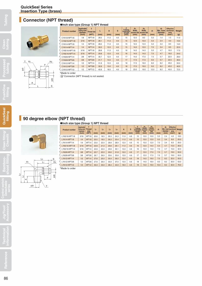
Tub
ing
Cle
an
tub
ing
Pu
sh
On
efi
ttin
gQ
uic
kS
ea
lfi
ttin
gB
amb
oo
-sh
oo
t fi
ttin
gC
ontr
ol s
witc
h/D
etac
habl
ese
ries
Cle
an f
itti
ng
/C
hem
ifit
Jig
/To
ol/
Accesso
ryR
efer
ence
Pro
cess
edtu
bin
gTe
chn
ical
info
rmat
ion
*
*
*
*
*
*
*
*
*
*
*
*
*
*
*
*
*
*
*
*
*
L1N3/16-NPT1/8
L1N1/4-NPT1/8
L1N1/4-NPT1/4
L1N5/16-NPT1/8
L1N5/16-NPT1/4
L1N3/8-NPT1/4
L1N3/8-NPT3/8
L1N1/2-NPT1/4
L1N1/2-NPT3/8
L1N1/2-NPT1/2
3/16
1/4
1/4
5/16
5/16
3/8
3/8
1/2
1/2
1/2
NPT1/8
NPT1/8
NPT1/4
NPT1/8
NPT1/4
NPT1/4
NPT3/8
NPT1/4
NPT3/8
NPT1/2
20.6
20.5
23.0
22.8
22.8
23.7
26.7
27.8
27.8
30.3
18.5
18.5
22.0
21.0
22.0
22.0
26.0
25.0
26.0
33.0
26.3
26.3
28.8
29.8
29.8
30.6
33.6
35.9
35.9
38.4
24.3
25.4
28.9
29.1
30.1
31.8
35.8
36.0
37.0
44.0
11.0
11.0
12.0
11.0
12.0
12.0
13.0
12.0
13.0
18.0
4.6
4.6
4.6
4.6
4.6
4.6
4.6
4.6
4.6
4.6
15
15
15
16
16
17
17
18
18
18
10.0
10.0
10.0
12.0
12.0
12.0
12.0
14.0
14.0
14.0
10.0
12.0
12.0
14.0
14.0
17.0
17.0
19.0
19.0
19.0
5.0
5.0
7.0
5.0
7.0
7.0
7.0
7.0
9.0
10.0
2.4
3.4
3.4
4.7
4.7
5.7
5.7
8.2
8.2
8.2
18.0
20.0
26.0
30.0
32.0
50.0
50.0
50.0
53.0
76.0
4.0
8.0
8.0
15.0
15.0
19.0
19.0
32.0
32.0
32.0
90 degree elbow (NPT thread)
C1N1/8-NPT1/8
C1N3/16-NPT1/8
C1N1/4-NPT1/8
C1N1/4-NPT1/4
C1N5/16-NPT1/8
C1N5/16-NPT1/4
C1N3/8-NPT1/4
C1N3/8-NPT3/8
C1N1/2-NPT1/4
C1N1/2-NPT3/8
C1N1/2-NPT1/2
1/8
3/16
1/4
1/4
5/16
5/16
3/8
3/8
1/2
1/2
1/2
NPT1/8
NPT1/8
NPT1/8
NPT1/4
NPT1/8
NPT1/4
NPT1/4
NPT3/8
NPT1/4
NPT3/8
NPT1/2
28.0
28.1
28.0
30.0
28.8
29.8
30.7
31.7
31.8
32.8
40.8
11.0
11.0
11.0
12.0
11.0
12.0
12.0
13.0
12.0
13.0
18.0
4.6
4.6
4.6
4.6
4.6
4.6
4.6
4.6
4.6
4.6
4.6
15
15
15
15
16
16
17
17
18
18
18
12.0
12.0
12.0
14.0
14.0
14.0
14.0
17.0
17.0
17.0
23.0
8.0
10.0
12.0
12.0
14.0
14.0
17.0
17.0
19.0
19.0
19.0
5.0
5.0
5.0
7.0
5.0
7.0
7.5
9.0
8.2
9.0
12.0
1.4
2.4
3.4
3.4
4.7
4.7
5.7
5.7
8.2
8.2
8.2
11.0
13.0
14.0
22.0
17.0
24.0
28.0
39.0
33.0
40.0
72.0
1.5
4.0
8.5
8.5
16.0
16.0
22.5
22.5
45.0
45.0
45.0
Inch size type (Group 1) NPT thread
Inch size type (Group 1) NPT thread
Connector (NPT thread)
*Made to order
Applicabletubing outerdiameter(inch)
TThread
size(NPT)
FTubing
insertionlength(mm)
d2Min. innerdiameter(mm)
H1Widthacross
flat(mm)
H2Widthacross
flat(mm)
Weight
(g)
Effectivesectional
area(mm2)
Product number d1
(mm)
L1
(mm)
L2
(mm)
L3
(mm)
L4
(mm)
A
(mm)
S
(mm)
Applicabletubing outerdiameter(inch)
TThread size
(NPT)
FTubing
insertion length(mm)
H2Width
across flat(mm)
H1Width
across flat(mm)
d2Min. innerdiameter
(mm)
Weight
(g)
Effectivesectional
area(mm2)
Product number d1
(mm)
L
(mm)
A
(mm)
S
(mm)
*Made to orderConnector (NPT thread) is not sealed.
86
φd2
T H1 H2
F
φd1
L S
A
φd1
AL2
L4
φd2
T
F
L3
L1 H2
SH1
QuickSeal SeriesInsertion Type (brass)

Tub
ing
Cle
an
tub
ing
Pu
sh
On
efi
ttin
gQ
uic
kS
ea
lfi
ttin
gB
amb
oo
-sh
oo
t fi
ttin
gC
ontr
ol s
witc
h/D
etac
habl
ese
ries
Cle
an f
itti
ng
/C
hem
ifit
Jig
/To
ol/
Accesso
ryR
efer
ence
Pro
cess
edtu
bin
gTe
chn
ical
info
rmat
ion
87

Tub
ing
Cle
an
tub
ing
Pu
sh
On
efi
ttin
gQ
uic
kS
ea
lfi
ttin
gB
amb
oo
-sh
oo
t fi
ttin
gC
ontr
ol s
witc
h/D
etac
habl
ese
ries
Cle
an f
itti
ng
/C
hem
ifit
Jig
/To
ol/
Accesso
ryR
efer
ence
Pro
cess
edtu
bin
gTe
chn
ical
info
rmat
ion
QuickSeal Series
Stainless (SUS304)
Features
Insertion Type (stainless)Screw-in type for multi-purpose piping (made of SUS304)
Handling instructions
Operating fluid, working temperature range
Pressure condition
Applicable tubing
Related products and product introduction Miniature valve Q.D.C 101 series
Maximum working pressure:5.0MPaNegative pressure performance:
−101.294kPa
Reference
Operating fluid Working temperature range
Air −40°C∼+80°CNylon sleeve
Nylon sleeveWater 0°C∼+70°CGeneraloperating oil −40°C∼+80°CNylon sleeve
See “Combination List of Tubing and Fitting”on page 8.
Contact us for various chemical liquids.
The inch size type has a black sleeve. The millimeter size type has a cut at the hexagonal nut.
Distinction of millimeter/inch sizes
Sealing mechanism
Product number example
Cross-sectional structure diagram
Polyurethane tubing Nylon tubing Polybutene tubing Polyolefin resin tubing Fluorocarbon resin tubing Polyurethane processed tubingAntistatic tubing
(*1) Combinatory use of PL, PN, TA, TP or ES tubing and QuickSeal series of insertion type (stainless) mixes general and clean type performances. When using them together in a clean environment, be aware of how this could lower the cleanliness level.
*1 *1
Flexible fluorocarbonresin bilayer tubing
TES UC USCUMC UML
Clean, Antistatic tubing
ESPBU2 U1 U5 N2 N5 N1 UE PL PN TA TP
Screw-in typeConsisting of three parts: fitting body, nut and sleeve.
High sealing performanceThe insertion part is integrated with a fitting body with high negative-pressure performance.
Made of SUS304 with high corrosion resistanceJIS B 8381-1995 (fittings for pneumatic flexible pipes) compliant
When the working conditions of tubes and fittings differ, use them under the lower specified conditions.
For use at a high temperature within the working temperature range, tighten the nut periodically. If the nut cannot be tightened further, cut the tubing end and insert the tubing again with a new sleeve.
When water is used as the operating fluid, do not allow it to freeze.
Do not bend the pipe sharply near the tubing insertion port (sleeve end) of the fitting. Keep the tubing straight for twice as long as the tubing diameter from the insertion port.
The outer and the inner diameters of the fitting have to be the same as those of the tubing used.
Caution:
Caution:
Caution:
Caution:
Caution:
See page 34 for the common handling instructions for fittings.
Instruction manual ·······P.172Chemical resistancespecification table ·········P.198Effective sectional area ··P.168Negative-pressureperformance list ··········P.169
Body (SUS304)
Insertion partNut (SUS304)
Thread part (SUS304) Nylon sleeve (nylon)Millimeter size: WhiteInch size : Black
InchMillimeter
Insertion part
Stress
Body
SleeveNut
Tubing
C4N 6×4 - PT1/8 - S
Shape, groupApplicable tubing outer diameter
Thread size
Cut
88

Tub
ing
Cle
an
tub
ing
Pu
sh
On
efi
ttin
gQ
uic
kS
ea
lfi
ttin
gB
amb
oo
-sh
oo
t fi
ttin
gC
ontr
ol s
witc
h/D
etac
habl
ese
ries
Cle
an f
itti
ng
/C
hem
ifit
Jig
/To
ol/
Accesso
ryR
efer
ence
Pro
cess
edtu
bin
gTe
chn
ical
info
rmat
ion
QuickSeal Series Insertion Type (stainless)Shape list
89
ConnectorC*N-S
90 degree elbowL*N-S
TeeT*N-S
Service teeST*N-S
Union connectorUC*N-S
90 degree union elbowUL*N-S
Union teeUT*N-S
Stainless nutN*-S
Nylon sleeveSN

Tub
ing
Cle
an
tub
ing
Pu
sh
On
efi
ttin
gQ
uic
kS
ea
lfi
ttin
gB
amb
oo
-sh
oo
t fi
ttin
gC
ontr
ol s
witc
h/D
etac
habl
ese
ries
Cle
an f
itti
ng
/C
hem
ifit
Jig
/To
ol/
Accesso
ryR
efer
ence
Pro
cess
edtu
bin
gTe
chn
ical
info
rmat
ion
C4N6×4-PT1/8-S
C4N6×4-PT1/4-S
C4N8×5-PT1/8-S
C4N8×5-PT1/4-S
C4N8×6-PT1/8-S
C4N8×6-PT1/4-S
C4N10×6.5-PT1/4-S
C4N10×6.5-PT3/8-S
C4N10×8-PT1/4-S
C4N10×8-PT3/8-S
C4N12×8-PT3/8-S
C4N12×8-PT1/2-S
C4N12×9-PT3/8-S
C4N12×9-PT1/2-S
6×4
6×4
8×5
8×5
8×6
8×6
10×6.5
10×6.5
10×8
10×8
12×8
12×8
12×9
12×9
R1/8
R1/4
R1/8
R1/4
R1/8
R1/4
R1/4
R3/8
R1/4
R3/8
R3/8
R1/2
R3/8
R1/2
28.0
30.0
27.9
29.9
27.9
29.9
31.1
32.1
31.1
32.1
35.6
40.6
35.6
40.6
11.0
12.0
11.0
12.0
11.0
12.0
12.0
13.0
12.0
13.0
13.0
18.0
13.0
18.0
4.6
4.6
4.6
4.6
4.6
4.6
4.2
4.2
4.2
4.2
4.8
4.8
4.8
4.8
15
15
16
16
16
16
17
17
17
17
18
18
18
18
10.0
14.0
12.0
14.0
12.0
14.0
17.0
17.0
17.0
17.0
17.0
23.0
17.0
23.0
12.0
12.0
14.0
14.0
14.0
14.0
17.0
17.0
17.0
17.0
19.0
19.0
19.0
19.0
5.0
7.0
5.0
7.0
5.0
7.0
7.0
9.0
7.0
9.0
9.0
12.0
9.0
12.0
2.7
2.7
3.7
3.7
4.7
4.7
5.2
5.2
6.7
6.7
6.6
6.6
7.6
7.6
15.0
22.0
18.0
24.0
17.0
24.0
32.0
38.0
29.0
37.0
47.0
75.0
40.5
74.0
5.0
5.0
10.0
10.0
16.0
16.0
20.5
20.5
32.0
32.0
32.0
33.5
40.0
40.0
C1N1/4-PT1/8-S
C1N1/4-PT1/4-S
C1N5/16-PT1/8-S
C1N5/16-PT1/4-S
C1N3/8-PT1/8-S
C1N3/8-PT1/4-S
C1N3/8-PT3/8-S
C1N1/2-PT1/4-S
C1N1/2-PT3/8-S
C1N1/2-PT1/2-S
1/4
1/4
5/16
5/16
3/8
3/8
3/8
1/2
1/2
1/2
R1/8
R1/4
R1/8
R1/4
R1/8
R1/4
R3/8
R1/4
R3/8
R1/2
28.0
30.0
27.8
29.8
28.7
30.7
31.7
31.8
32.8
40.8
11.0
12.0
11.0
12.0
11.0
12.0
13.0
12.0
13.0
18.0
4.6
4.6
4.6
4.6
4.6
4.6
4.6
4.6
4.6
4.6
15
15
16
16
17
17
17
18
18
18
10.0
14.0
12.0
14.0
14.0
14.0
17.0
17.0
17.0
23.0
12.0
12.0
14.0
14.0
17.0
17.0
17.0
19.0
19.0
19.0
5.0
7.0
5.0
7.0
5.7
7.5
9.0
8.2
9.0
12.0
3.4
3.4
4.7
4.7
5.7
5.7
5.7
8.2
8.2
8.2
14.0
22.0
17.0
24.0
23.0
28.0
39.0
33.0
40.0
72.0
8.5
8.5
16.0
16.0
22.5
22.5
22.5
45.0
45.0
45.0
L4N6×4-PT1/8-S
L4N6×4-PT1/4-S
L4N8×5-PT1/8-S
L4N8×5-PT1/4-S
L4N8×6-PT1/8-S
L4N8×6-PT1/4-S
L4N10×6.5-PT1/4-S
L4N10×6.5-PT3/8-S
L4N10×8-PT1/4-S
L4N10×8-PT3/8-S
L4N12×8-PT3/8-S
L4N12×8-PT1/2-S
L4N12×9-PT3/8-S
L4N12×9-PT1/2-S
6×4
6×4
8×5
8×5
8×6
8×6
10×6.5
10×6.5
10×8
10×8
12×8
12×8
12×9
12×9
R1/8
R1/4
R1/8
R1/4
R1/8
R1/4
R1/4
R3/8
R1/4
R3/8
R3/8
R1/2
R3/8
R1/2
20.5
23.0
22.9
22.9
22.9
22.9
27.1
27.1
27.1
27.1
27.6
30.1
27.6
30.1
18.5
22.0
21.0
22.0
21.0
22.0
25.0
26.0
25.0
26.0
26.0
33.0
26.0
33.0
26.3
29.9
29.8
29.8
29.8
29.8
35.2
35.2
35.2
35.2
35.7
40.5
35.7
40.5
25.4
28.9
29.1
30.1
29.1
30.1
34.8
35.8
34.8
35.8
37.0
44.0
37.0
44.0
11.0
12.0
11.0
12.0
11.0
12.0
12.0
13.0
12.0
13.0
13.0
18.0
13.0
18.0
4.6
4.6
4.6
4.6
4.6
4.6
4.2
4.2
4.2
4.2
4.8
4.8
4.8
4.8
15
15
16
16
16
16
17
17
17
17
18
18
18
18
10.0
12.0
12.0
12.0
12.0
12.0
14.0
14.0
14.0
14.0
14.0
18.0
14.0
18.0
12.0
12.0
14.0
14.0
14.0
14.0
17.0
17.0
17.0
17.0
19.0
19.0
19.0
19.0
5.0
7.0
5.0
7.0
5.0
7.0
7.0
9.0
7.0
9.0
9.0
10.0
9.0
10.0
2.7
2.7
3.7
3.7
4.7
4.7
5.2
5.2
6.7
6.7
6.6
6.6
7.6
7.6
21.0
32.0
31.0
32.5
31.0
32.5
47.0
50.0
48.0
51.0
53.0
90.0
54.0
91.0
4.5
4.5
9.0
9.0
14.0
15.0
18.0
18.0
25.0
25.0
25.0
30.0
33.0
33.0
L1N1/4-PT1/8-S
L1N1/4-PT1/4-S
L1N5/16-PT1/8-S
L1N5/16-PT1/4-S
L1N3/8-PT1/8-S
L1N3/8-PT1/4-S
L1N3/8-PT3/8-S
L1N1/2-PT1/4-S
L1N1/2-PT3/8-S
L1N1/2-PT1/2-S
1/4
1/4
5/16
5/16
3/8
3/8
3/8
1/2
1/2
1/2
R1/8
R1/4
R1/8
R1/4
R1/8
R1/4
R3/8
R1/4
R3/8
R1/2
20.5
23.0
22.8
22.8
23.7
23.7
26.7
27.8
27.8
30.8
18.5
22.0
21.0
22.0
21.0
22.0
26.0
25.0
26.0
33.0
26.3
30.0
29.8
29.8
30.6
30.6
35.2
35.9
36.3
41.6
25.4
28.9
29.1
30.1
30.8
31.8
35.8
36.0
37.0
44.0
11.0
12.0
11.0
12.0
11.0
12.0
13.0
12.0
13.0
18.0
4.6
4.6
4.6
4.6
4.6
4.6
4.6
4.6
4.6
4.6
15
15
16
16
17
17
17
18
18
18
10.0
12.0
12.0
12.0
12.0
12.0
14.0
14.0
14.0
18.0
12.0
12.0
14.0
14.0
17.0
17.0
17.0
19.0
19.0
19.0
5.0
7.0
5.0
7.0
5.0
7.0
9.0
7.0
9.0
12.0
3.4
3.4
4.7
4.7
5.7
5.7
5.7
8.2
8.2
8.2
20.0
26.0
30.0
32.0
35.0
50.0
50.0
50.0
53.0
76.0
8.0
8.0
15.0
15.0
15.0
19.0
19.0
32.0
32.0
32.0
Connector
Inch size type (Group 1)
Millimeter size type (Group 4)
Inch size type (Group 1)
Millimeter size type (Group 4)
90 degree elbow
Applicabletubing outer
diameter×innerdiameter(mm)
TThread size
(R)
FTubing
insertion length(mm)
H2Width
across flat(mm)
H1Width
across flat(mm)
d2Min. innerdiameter
(mm)
Weight
(g)
Effectivesectional
area(mm2)
Product number d1
(mm)
L
(mm)
A
(mm)
S
(mm)
Applicabletubing outer
diameter(inch)
TThread size
(R)
FTubing
insertion length(mm)
H2Width
across flat(mm)
H1Width
across flat(mm)
d2Min. innerdiameter
(mm)
Weight
(g)
Effectivesectional
area(mm2)
Product number d1
(mm)
L
(mm)
A
(mm)
S
(mm)
Applicabletubing outer
diameter×innerdiameter(mm)
TThread
size(R)
FTubing
insertionlength(mm)
d2Min. innerdiameter(mm)
H1Widthacross
flat(mm)
H2Widthacross
flat(mm)
Weight
(g)
Effectivesectional
area(mm2)
Product number d1
(mm)
L1
(mm)
L2
(mm)
L3
(mm)
L4
(mm)
A
(mm)
S
(mm)
Applicabletubing outer
diameter(inch)
TThread
size(R)
FTubing
insertionlength(mm)
d2Min. innerdiameter(mm)
H1Widthacross
flat(mm)
H2Widthacross
flat(mm)
Weight
(g)
Effectivesectional
area(mm2)
Product number d1
(mm)
L1
(mm)
L2
(mm)
L3
(mm)
L4
(mm)
A
(mm)
S
(mm)
90
φd2
T H1 H2
F
φd1
L S
A
φd1
AL2
L4
φd2
T
F
L3
L1 H2
S
H1
QuickSeal SeriesInsertion Type (stainless)

Tub
ing
Cle
an
tub
ing
Pu
sh
On
efi
ttin
gQ
uic
kS
ea
lfi
ttin
gB
amb
oo
-sh
oo
t fi
ttin
gC
ontr
ol s
witc
h/D
etac
habl
ese
ries
Cle
an f
itti
ng
/C
hem
ifit
Jig
/To
ol/
Accesso
ryR
efer
ence
Pro
cess
edtu
bin
gTe
chn
ical
info
rmat
ion
TeeMillimeter size type (Group 4)
T4N6×4-PT1/8-S
T4N6×4-PT1/4-S
T4N8×5-PT1/8-S
T4N8×5-PT1/4-S
T4N8×6-PT1/8-S
T4N8×6-PT1/4-S
T4N10×6.5-PT1/4-S
T4N10×6.5-PT3/8-S
T4N10×8-PT1/4-S
T4N10×8-PT3/8-S
T4N12×8-PT3/8-S
T4N12×9-PT3/8-S
R1/8
R1/4
R1/8
R1/4
R1/8
R1/4
R1/4
R3/8
R1/4
R3/8
R3/8
R3/8
6×4
6×4
8×5
8×5
8×6
8×6
10×6.5
10×6.5
10×8
10×8
12×8
12×9
20.5
23.0
22.9
22.9
22.9
22.9
27.1
27.1
27.1
27.1
27.6
27.6
18.5
22.0
21.0
22.0
21.0
22.0
25.0
26.0
25.0
26.0
25.0
26.0
25.4
28.9
29.1
30.1
29.1
30.1
34.8
35.8
34.8
35.8
36.0
37.0
41.0
46.0
45.8
45.8
45.8
45.8
54.2
54.2
54.2
54.2
55.3
55.3
11.0
12.0
11.0
12.0
11.0
12.0
12.0
13.0
12.0
13.0
13.0
13.0
4.6
4.6
4.6
4.6
4.6
4.6
4.2
4.2
4.2
4.2
4.8
4.8
15
15
16
16
16
16
17
17
17
17
18
18
10.0
12.0
12.0
12.0
12.0
12.0
14.0
14.0
14.0
14.0
14.0
14.0
12.0
12.0
14.0
14.0
14.0
14.0
17.0
17.0
17.0
17.0
19.0
19.0
5.0
7.0
5.0
7.0
5.0
7.0
7.0
9.0
7.0
9.0
9.0
9.0
2.7
2.7
3.7
3.7
4.7
4.7
5.2
5.2
6.7
6.7
6.6
7.6
30.0
43.0
43.0
45.0
42.0
44.0
73.0
78.0
69.0
75.0
82.0
82.0
4.5
4.5
9.0
9.0
14.0
15.0
18.0
18.0
25.0
25.0
25.0
33.0
Inch size type (Group 1)
T1N1/4-PT1/8-S
T1N1/4-PT1/4-S
T1N3/8-PT1/4-S
R1/8
R1/4
R1/4
1/4
1/4
3/8
20.5
23.0
23.7
18.5
22.0
22.0
25.4
28.9
31.8
41.1
46.1
47.4
11.0
12.0
12.0
4.6
4.6
4.6
15
15
17
10.0
12.0
12.0
12.0
12.0
17.0
5.0
7.0
7.0
3.4
3.4
5.7
29.0
42.0
55.0
8.0
8.0
19.0
Service teeMillimeter size type (Group 4)
ST4N6×4-PT1/8-S
ST4N6×4-PT1/4-S
ST4N8×5-PT1/8-S
ST4N8×5-PT1/4-S
ST4N8×6-PT1/8-S
ST4N8×6-PT1/4-S
ST4N10×6.5-PT1/4-S
ST4N10×6.5-PT3/8-S
ST4N10×8-PT1/4-S
ST4N10×8-PT3/8-S
ST4N12×8-PT3/8-S
ST4N12×9-PT3/8-S
R1/8
R1/4
R1/8
R1/4
R1/8
R1/4
R1/4
R3/8
R1/4
R3/8
R3/8
R3/8
6×4
6×4
8×5
8×5
8×6
8×6
10×6.5
10×6.5
10×8
10×8
12×8
12×9
20.5
23.0
22.9
22.9
22.9
22.9
27.1
27.1
27.1
27.1
27.6
27.6
18.5
22.0
21.0
22.0
21.0
22.0
25.0
26.0
25.0
26.0
26.0
26.0
20.5
23.0
22.9
22.9
22.9
22.9
27.1
27.1
27.1
27.1
27.6
27.6
39.0
45.0
43.9
44.9
43.9
44.9
52.1
53.1
52.1
53.1
53.6
53.6
27.4
29.9
31.0
31.0
31.0
31.0
36.9
36.9
36.9
36.9
38.6
38.6
11.0
12.0
11.0
12.0
11.0
12.0
12.0
13.0
12.0
13.0
13.0
13.0
4.6
4.6
4.6
4.6
4.6
4.6
4.2
4.2
4.2
4.2
4.8
4.8
15
15
16
16
16
16
17
17
17
17
18
18
10.0
12.0
12.0
12.0
12.0
12.0
14.0
14.0
14.0
14.0
14.0
14.0
12.0
12.0
14.0
14.0
14.0
14.0
17.0
17.0
17.0
17.0
19.0
19.0
5.0
7.0
5.0
7.0
5.0
7.0
7.0
9.0
7.0
9.0
9.0
9.0
2.7
2.7
3.7
3.7
4.7
4.7
5.2
5.2
6.7
6.7
6.6
7.6
41.0
30.0
43.0
43.0
45.0
46.0
72.0
70.0
76.0
113.0
81.0
130.0
4.5
4.5
9.0
9.0
14.0
15.0
18.0
18.0
25.0
25.0
25.0
33.0
Inch size type (Group 1)
ST1N1/4-PT1/8-S R1/81/4 20.5 18.5 20.5 39.0 27.5 11.0 4.6 15 10.0 12.0 5.0 3.4 29.08.0
Applicabletubing outer
diameter×innerdiameter(mm)
TThread
size(R)
FTubing
insertionlength(mm)
d2Min. innerdiameter(mm)
H1Widthacross
flat(mm)
H2Widthacross
flat(mm)
Weight
(g)
Effectivesectional
area(mm2)
Product number d1
(mm)
L1
(mm)
L2
(mm)
L4
(mm)
L5
(mm)
A
(mm)
S
(mm)
Applicabletubing outer
diameter(inch)
TThread
size(R)
FTubing
insertionlength(mm)
d2Min. innerdiameter(mm)
H1Widthacross
flat(mm)
H2Widthacross
flat(mm)
Weight
(g)
Effectivesectional
area(mm2)
Product number d1
(mm)
L1
(mm)
L2
(mm)
L4
(mm)
L5
(mm)
A
(mm)
S
(mm)
Applicabletubing outer
diameter×innerdiameter(mm)
TThread
size(R)
FTubing
insertionlength(mm)
d2Min. innerdiameter(mm)
H1Widthacross
flat(mm)
H2Widthacross
flat(mm)
Weight
(g)
Effectivesectional
area(mm2)
Product number d1
(mm)
L1
(mm)
L2
(mm)
L6
(mm)
L7
(mm)
L8
(mm)
A
(mm)
S
(mm)
Applicabletubing outer
diameter(inch)
TThread
size(R)
FTubing
insertionlength(mm)
d2Min. innerdiameter(mm)
H1Widthacross
flat(mm)
H2Widthacross
flat(mm)
Weight
(g)
Effectivesectional
area(mm2)
Product number d1
(mm)
L1
(mm)
L2
(mm)
L6
(mm)
L7
(mm)
L8
(mm)
A
(mm)
S
(mm)
91
φd1
L4
φd2
L5
L1H1 H2
S
T
FL2
A
φd2
L6
φd1
L2 L1
L7
A H1
H2
T F
L8
S
QuickSeal SeriesInsertion Type (stainless)

Tub
ing
Cle
an
tub
ing
Pu
sh
On
efi
ttin
gQ
uic
kS
ea
lfi
ttin
gB
amb
oo
-sh
oo
t fi
ttin
gC
ontr
ol s
witc
h/D
etac
habl
ese
ries
Cle
an f
itti
ng
/C
hem
ifit
Jig
/To
ol/
Accesso
ryR
efer
ence
Pro
cess
edtu
bin
gTe
chn
ical
info
rmat
ion
33.0
32.8
32.8
36.2
36.2
37.3
37.3
4.6
4.6
4.6
4.2
4.2
4.8
4.8
15
16
16
17
17
18
18
10.0
12.0
12.0
17.0
17.0
17.0
17.0
12.0
14.0
14.0
17.0
17.0
19.0
19.0
2.7
3.7
4.7
5.2
6.7
6.6
7.6
20.0
28.0
25.0
44.0
44.0
49.0
51.0
UC4N6×4-S
UC4N8×5-S
UC4N8×6-S
UC4N10×6.5-S
UC4N10×8-S
UC4N12×8-S
UC4N12×9-S
6×4
8×5
8×6
10×6.5
10×8
12×8
12×9
5.0
10.0
16.0
20.5
32.0
32.0
40.0
UC1N1/4-S
UC1N5/16-S
UC1N3/8-S
UC1N1/2-S
33.1
32.7
35.4
37.6
4.6
4.6
4.6
4.6
15
16
17
18
10.0
12.0
14.0
17.0
12.0
14.0
17.0
19.0
3.4
4.7
5.7
8.2
20.0
25.0
40.0
47.0
1/4
5/16
3/8
1/2
8.5
16.0
22.5
45.0
Millimeter size type (Group 4)
UL4N6×4-S
UL4N8×5-S
UL4N8×6-S
UL4N10×6.5-S
UL4N10×8-S
UL4N12×8-S
UL4N12×9-S
6×4
8×5
8×6
10×6.5
10×8
12×8
12×9
20.5
22.9
22.9
27.1
27.1
27.6
27.6
27.4
31.0
31.0
36.9
36.9
38.6
38.6
4.6
4.6
4.6
4.2
4.2
4.8
4.8
15
16
16
17
17
18
18
10.0
12.0
12.0
14.0
14.0
14.0
14.0
12.0
14.0
14.0
17.0
17.0
19.0
19.0
2.7
3.7
4.7
5.2
6.7
6.6
7.6
25.0
37.0
36.0
59.0
57.0
63.0
60.0
4.0
7.5
12.5
15.5
25.0
25.0
25.0
Inch size type (Group 1)
UT1N1/4-S
UT1N5/16-S
UT1N3/8-S
UT1N1/2-S
1/4
5/16
3/8
1/2
20.5
22.8
23.7
27.8
41.1
45.7
47.4
55.6
20.5
22.8
23.7
27.8
27.5
30.9
33.5
38.8
4.6
4.6
4.6
4.6
15
16
17
18
10.0
12.0
12.0
14.0
12.0
14.0
17.0
19.0
3.4
4.7
5.7
8.2
34.0
49.0
64.0
84.0
6.5
12.5
18.5
30.0
Millimeter size type (Group 4)
UT4N6×4-S
UT4N8×5-S
UT4N8×6-S
UT4N10×6.5-S
UT4N10×8-S
UT4N12×8-S
UT4N12×9-S
6×4
8×5
8×6
10×6.5
10×8
12×8
12×9
20.5
22.9
22.9
27.1
27.1
27.6
27.6
41.0
45.8
45.8
54.2
54.2
55.3
55.3
20.5
22.9
22.9
27.1
27.1
28.6
28.6
27.4
31.0
31.0
36.9
36.9
39.6
39.6
4.6
4.6
4.6
4.2
4.2
4.8
4.8
15
16
16
17
17
18
18
10.0
12.0
12.0
14.0
14.0
14.0
14.0
12.0
14.0
14.0
17.0
17.0
19.0
19.0
2.7
3.7
4.7
5.2
6.7
6.6
7.6
35.0
49.0
48.0
82.0
77.0
90.0
85.0
4.0
7.5
12.5
15.5
25.0
25.0
25.0
*Made to order
*
Union connector
90 degree union elbow
Union tee
Millimeter size type (Group 4)
Inch size type (Group 1)
Applicabletubing outer
diameter×innerdiameter(mm)
FTubing insertion
length(mm)
H2Width
across flat(mm)
H1Width
across flat(mm)
d2Min. innerdiameter
(mm)
Weight
(g)
Effectivesectional
area(mm2)
Product number L
(mm)
S
(mm)
Applicabletubing outer
diameter(inch)
FTubing insertion
length(mm)
H2Width
across flat(mm)
H1Width
across flat(mm)
d2Min. innerdiameter
(mm)
Weight
(g)
Effectivesectional
area(mm2)
Product number L
(mm)
S
(mm)
Applicabletubing outer
diameter×innerdiameter(mm)
FTubing
insertion length(mm)
H2Width
across flat(mm)
H1Width
across flat(mm)
d2Min. innerdiameter
(mm)
Weight
(g)
Effectivesectional
area(mm2)
Product number L1
(mm)
L8
(mm)
S
(mm)
Applicabletubing outer
diameter(inch)
FTubing
insertion length(mm)
H2Width
across flat(mm)
H1Width
across flat(mm)
d2Min. innerdiameter
(mm)
Weight
(g)
Effectivesectional
area(mm2)
Product number L1
(mm)
L5
(mm)
L6
(mm)
L8
(mm)
S
(mm)
Applicabletubing outer
diameter×innerdiameter(mm)
FTubing
insertion length(mm)
H2Width
across flat(mm)
H1Width
across flat(mm)
d2Min. innerdiameter
(mm)
Weight
(g)
Effectivesectional
area(mm2)
Product number L1
(mm)
L5
(mm)
L6
(mm)
L8
(mm)
S
(mm)
92
φd2
FH2H1
L S
φd2
H2
H1 L1
L8 S
F
L8
φd2
H2
H1
L5 S
F
L8
L1
L6
QuickSeal SeriesInsertion Type (stainless)

Tub
ing
Cle
an
tub
ing
Pu
sh
On
efi
ttin
gQ
uic
kS
ea
lfi
ttin
gB
amb
oo
-sh
oo
t fi
ttin
gC
ontr
ol s
witc
h/D
etac
habl
ese
ries
Cle
an f
itti
ng
/C
hem
ifit
Jig
/To
ol/
Accesso
ryR
efer
ence
Pro
cess
edtu
bin
gTe
chn
ical
info
rmat
ion
Applicable tubingouter diameter
(inch)Product number
TThread size
(M)
Weight
(g)
H2Width
across flat(mm)
L
(mm)
N1/4-S
N5/16-S
N3/8-S
N1/2-S
1/4
5/16
3/8
1/2
M10×1.0
M12×1.0
M14×1.0
M17×1.0
9.0
9.0
10.0
11.5
12.0
14.0
17.0
19.0
5.0
6.0
10.0
11.0
Applicable tubingouter diameter
(mm)Product number
TThread size
(M)
Weight
(g)
H2Width
across flat(mm)
L
(mm)
N6-S
N8-S
N10-S
N12-S
6
8
10
12
M10×1.0
M12×1.0
M15×1.0
M17×1.0
9.0
9.0
10.0
11.0
12.0
14.0
17.0
19.0
5.0
6.0
9.0
11.0
Product
number
SN6
SN8
SN10
SN12
6
8
10
12
Applicable tubingouter diameter
(mm)
L
(mm)
11.0
11.0
12.0
13.0
Weight
(g)
0.2
0.3
0.4
0.5
Weight
(g)
0.2
0.3
0.4
0.5
Product
number
SN1/4
SN5/16
SN3/8
SN1/2
1/4
5/16
3/8
1/2
Applicable tubingouter diameter
(inch)
L
(mm)
11.0
11.0
12.0
13.0
Inch size type (Group 1)
Millimeter size type (Group 4)Stainless nut
Millimeter size type (Color: milky white)Nylon sleeve
Inch size type (Color: black)
*The inch size type has no cut.
93
H2
T
L
L
QuickSeal SeriesInsertion Type (stainless)
Caution: Nylon sleeves that have been used once cannot be reused.

Tub
ing
Cle
an
tub
ing
Pu
sh
On
efi
ttin
gQ
uic
kS
ea
lfi
ttin
gB
amb
oo
-sh
oo
t fi
ttin
gC
ontr
ol s
witc
h/D
etac
habl
ese
ries
Cle
an f
itti
ng
/C
hem
ifit
Jig
/To
ol/
Accesso
ryR
efer
ence
Pro
cess
edtu
bin
gTe
chn
ical
info
rmat
ion
QuickSeal Series
Handling instructions
Operating fluid, working temperature range
Pressure condition
Applicable tubingProduct number example
Cross-sectional structure diagram
Features
Insertless Type
Screw-in typeConsisting of three parts: fitting body, nut and sleeve.
Large flow volumeLarge effective sectional area due to lack of an insertion part.
Only the connector is sealedSealing tape is not required.
Maximum working pressure:1.0MPaNegative pressure performance:
−99.975kPa
Reference
Screw-in type for general pneumatic piping
Operating fluid Working temperature range
Air −40°C∼+100°C
QuickSeal Series Insertless type (brass)Shape list
See “Combination List of Tubing and Fitting” on page 8.
Nylon tubing4A01 - 2402
ShapeApplicable tubing diameterand thread size
Instruction manual ·······················P.172Effective sectional area ················P.168Negative-pressure performance list ··P.169
N2 N5 N1
When the working conditions of tubes and fittings differ, use them under the lower specified conditions.
For use at a high temperature within the working temperature range, tighten the nut periodically. If the nut cannot be tightened further, cut the tubing end and insert the tubing again with a new sleeve.
Do not bend the pipe sharply near the tubing insertion port (sleeve end) of the fitting. Keep the tubing straight for twice as long as the tubing diameter from the insertion port.
Caution:
Caution:
Caution:
See page 34 for the common handling instructions for fittings.
Body (brass)
Nut (brass)
Sleeve (brass)
Thread part (brass)Only the connector is sealed.(Fluorocarbon resin coating)
P.95
94
Connector4A01
90 degree elbow4A02
Tee4A03
Service tee4A04
Union tee4A05
Swivel nut internal connector4A06
Union connector4A07
90 degree union elbow4A08
Brass nutN
Brass sleeveMSN

Tub
ing
Cle
an
tub
ing
Pu
sh
On
efi
ttin
gQ
uic
kS
ea
lfi
ttin
gB
amb
oo
-sh
oo
t fi
ttin
gC
ontr
ol s
witc
h/D
etac
habl
ese
ries
Cle
an f
itti
ng
/C
hem
ifit
Jig
/To
ol/
Accesso
ryR
efer
ence
Pro
cess
edtu
bin
gTe
chn
ical
info
rmat
ion
4A03-2402
4A03-2602
4A03-2604
4A03-2802
4A03-2804
4A03-3004
4A03-3006
4A03-3206
4A03-3208
4
6
6
8
8
10
10
12
12
R1/8
R1/8
R1/4
R1/8
R1/4
R1/4
R3/8
R3/8
R1/2
20.4
20.4
22.9
22.8
22.8
27.0
27.0
27.5
30.5
11.0
11.0
12.0
11.0
12.0
12.0
13.0
13.0
18.0
2.7
2.6
2.6
2.6
2.6
2.3
2.3
3.1
3.1
14
14
14
15
15
18
18
19
19
10.0
12.0
12.0
14.0
14.0
17.0
17.0
19.0
19.0
10.0
10.0
12.0
12.0
12.0
14.0
14.0
14.0
18.0
5.0
5.0
7.0
5.0
7.0
7.0
9.0
9.0
12.0
2.0
4.0
4.0
5.0
6.0
7.0
7.5
8.0
8.0
27.0
29.0
43.0
42.0
43.0
69.0
73.0
79.0
125.0
18.5
18.5
22.0
21.0
22.0
25.0
26.0
26.0
33.0
24.3
25.4
28.9
29.1
30.1
34.8
35.8
37.0
44.0
40.8
40.8
45.8
45.7
45.7
53.9
53.9
54.9
60.9
3.0
9.0
10.0
16.0
22.0
30.0
35.0
40.0
40.0
4A01-2402
4A01-2602
4A01-2604
4A01-2802
4A01-2804
4A01-3004
4A01-3006
4A01-3206
4A01-3208
4
6
6
8
8
10
10
12
12
R1/8
R1/8
R1/4
R1/8
R1/4
R1/4
R3/8
R3/8
R1/2
27.9
27.9
29.9
27.8
29.8
31.0
32.0
32.5
40.5
11.0
11.0
12.0
11.0
12.0
12.0
13.0
13.0
18.0
2.7
2.6
2.6
2.6
2.6
2.3
2.3
3.1
3.1
14
14
14
15
15
18
18
19
19
10.0
12.0
12.0
14.0
14.0
17.0
17.0
19.0
19.0
10.0
10.0
14.0
12.0
14.0
17.0
17.0
17.0
24.0
5.0
5.0
7.0
5.0
7.0
7.5
9.0
9.0
12.0
2.0
4.0
4.0
5.0
6.0
7.5
7.5
8.0
8.0
13.0
15.0
23.0
17.0
24.0
31.0
38.0
40.0
71.0
3.0
10.0
10.0
18.0
25.0
39.0
39.0
45.0
45.0
4A02-2402
4A02-2602
4A02-2604
4A02-2802
4A02-2804
4A02-3004
4A02-3006
4A02-3206
4A02-3208
4
6
6
8
8
10
10
12
12
R1/8
R1/8
R1/4
R1/8
R1/4
R1/4
R3/8
R3/8
R1/2
20.4
20.4
22.9
22.8
22.8
27.0
27.0
27.5
30.0
11.0
11.0
12.0
11.0
12.0
13.5
13.0
13.0
18.0
2.7
2.6
2.6
2.6
2.6
2.3
2.3
3.1
3.1
14
14
14
15
15
18
18
19
19
10.0
12.0
12.0
14.0
14.0
17.0
17.0
19.0
19.0
10.0
10.0
12.0
12.0
12.0
14.0
14.0
14.0
14.0
5.0
5.0
7.0
5.0
7.0
7.0
9.0
9.0
10.0
2.0
4.0
4.0
5.0
6.0
7.0
7.5
8.0
8.0
19.0
20.0
30.0
29.0
32.0
46.0
82.0
53.0
90.0
18.5
18.5
22.0
21.0
22.0
25.0
26.0
26.0
33.0
26.2
26.2
29.9
29.8
29.8
35.1
35.5
36.0
40.8
24.3
25.4
28.9
29.1
30.1
34.8
35.8
37.0
44.0
3.0
9.0
10.0
16.0
22.0
30.0
35.0
40.0
40.0
Only the connector is sealed.
TeeMillimeter size type
Applicabletubing outer
diameter(mm)
TThread
size(R)
FTubing
insertionlength(mm)
Min. innerdiameter(mm)
H1Widthacross
flat(mm)
H2Widthacross
flat(mm)
Weight
(g)
Effectivesectional
area(mm2)
Product number d1
(mm)
L1
(mm)
L2
(mm)
L4
(mm)
L5
(mm)
A
(mm)
S
(mm)
ConnectorMillimeter size type
Applicabletubing outer
diameter(mm)
TThread size
(R)
FTubing
insertion length(mm)
H2Width
across flat(mm)
H1Width
across flat(mm)
Min. innerdiameter
(mm)
Weight
(g)
Effectivesectional
area(mm2)
Product number d1
(mm)
L
(mm)
A
(mm)
S
(mm)
Millimeter size type 90 degree elbow
Applicabletubing outer
diameter(mm)
TThread
size(R)
FTubing
insertionlength(mm)
Min. innerdiameter(mm)
H1Widthacross
flat(mm)
H2Widthacross
flat(mm)
Weight
(g)
Effectivesectional
area(mm2)
Product number d1
(mm)
L1
(mm)
L2
(mm)
L3
(mm)
L4
(mm)
A
(mm)
S
(mm)
95
H2H1
SL
A
φd1
FT
L3 S
L4L2
A
L1H1 H2
F
Tφd1
SL5
L4
L2
A
F
T
L1H1 H2
φd1
QuickSeal SeriesInsertless Type

Tub
ing
Cle
an
tub
ing
Pu
sh
On
efi
ttin
gQ
uic
kS
ea
lfi
ttin
gB
amb
oo
-sh
oo
t fi
ttin
gC
ontr
ol s
witc
h/D
etac
habl
ese
ries
Cle
an f
itti
ng
/C
hem
ifit
Jig
/To
ol/
Accesso
ryR
efer
ence
Pro
cess
edtu
bin
gTe
chn
ical
info
rmat
ion
Millimeter size typeUnion tee
Millimeter size typeService tee
4A04-2402
4A04-2602
4A04-2604
4A04-2802
4A04-2804
4A04-3004
4A04-3006
4A04-3206
4A04-3208
4
6
6
8
8
10
10
12
12
R1/8
R1/8
R1/4
R1/8
R1/4
R1/4
R3/8
R3/8
R1/2
20.4
20.4
22.9
22.8
22.8
27.0
27.0
27.5
30.5
11.0
11.0
12.0
12.0
12.0
12.0
13.0
13.0
18.0
2.7
2.6
2.6
2.6
2.6
2.3
2.3
3.1
3.1
14
14
14
15
15
18
18
19
19
10.0
12.0
12.0
14.0
14.0
17.0
17.0
19.0
19.0
10.0
10.0
12.0
12.0
12.0
14.0
14.0
14.0
18.0
5.0
5.0
7.0
5.0
7.0
7.0
9.0
9.0
12.0
2.0
4.0
4.0
5.0
6.0
7.0
7.5
8.0
8.0
27.0
29.0
37.0
41.0
43.0
70.0
73.0
80.0
127.0
18.5
18.5
22.0
21.0
22.0
25.0
26.0
26.0
35.5
20.4
20.4
22.9
22.8
22.8
27.0
27.0
27.5
30.5
38.9
38.9
44.9
43.8
44.8
52.0
53.0
53.5
66.0
26.2
27.4
29.9
30.9
30.9
36.8
36.8
38.4
41.4
3.0
9.0
10.0
16.0
22.0
30.0
35.0
40.0
40.0
4A05-2400
4A05-2600
4A05-2800
4A05-3000
4A05-3200
4
6
8
10
12
20.4
20.4
22.8
27.0
27.5
2.7
2.6
2.6
2.3
3.1
14
14
15
18
19
10.0
12.0
14.0
17.0
19.0
10.0
10.0
12.0
14.0
14.0
2.0
4.0
6.0
7.5
8.0
30.0
34.0
45.0
74.0
85.0
40.8
40.8
45.7
53.9
54.9
20.4
20.4
22.8
27.0
27.5
26.2
27.4
30.9
36.8
38.4
3.0
8.0
20.0
31.0
37.0
Millimeter size typeSwivel nut internal connector
4A06-2402
4A06-2602
4A06-2604
4A06-2804
4A06-3006
4A06-3206
4A06-3208
4
6
6
8
10
12
12
G1/8
G1/8
G1/4
G1/4
G3/8
G3/8
G1/2
32.9
32.9
34.6
34.5
40.8
41.3
51.0
14
14
14
15
18
19
19
10.0
12.0
12.0
14.0
17.0
19.0
19.0
12.0
12.0
17.0
17.0
19.0
19.0
22.0
3.0
3.0
5.0
5.0
8.0
8.0
10.0
3.0
3.0
5.0
5.0
8.0
8.0
10.0
24.0
25.0
43.0
45.0
75.0
67.0
115.0
2.7
2.6
2.6
2.6
2.3
3.1
3.1
4.0
4.0
5.7
5.7
6.8
6.8
9.5
14.0
14.0
19.0
19.0
22.0
22.0
27.0
5.0
5.0
7.0
7.0
10.0
10.0
14.0
3.5
6.5
10.0
18.0
42.0
45.0
54.0
*Made to order
*
*
*
*
*
*Made to order
*
*
*
*
*
Applicabletubing outer
diameter(mm)
FTubing
insertion length(mm)
H2Width
across flat(mm)
H1Width
across flat(mm)
Min. innerdiameter
(mm)
Weight
(g)
Effectivesectional
area(mm2)
Product number L1
(mm)
L5
(mm)
L6
(mm)
L8
(mm)
S
(mm)
Applicabletubing outer
diameter(mm)
TThread
size(R)
FTubing
insertionlength(mm)
Min. innerdiameter(mm)
H1Widthacross
flat(mm)
H2Widthacross
flat(mm)
Weight
(g)
Effectivesectional
area(mm2)
Product number d1
(mm)
L1
(mm)
L2
(mm)
L6
(mm)
L7
(mm)
L8
(mm)
A
(mm)
S
(mm)
Applicabletubing outer
diameter(mm)
TThread
size(G)
FTubing
insertionlength(mm)
Min. innerdiameter
(mm)
H1Width
across flat(mm)
H2Width
across flat(mm)
H3Width
across flat(mm)
Weight
(g)
Effectivesectional
area(mm2)
Product number d1
(mm)
C
(mm)
L
(mm)
I
(mm)
S
(mm)
96
L7
L2
L6L8
A H1
F
L1
S
φd1
T
H2
S
F
L5
L1H1
H2
L8L6
H3
T L S
H1 H2
I F
φC φd1 30
°
QuickSeal SeriesInsertless Type

Tub
ing
Cle
an
tub
ing
Pu
sh
On
efi
ttin
gQ
uic
kS
ea
lfi
ttin
gB
amb
oo
-sh
oo
t fi
ttin
gC
ontr
ol s
witc
h/D
etac
habl
ese
ries
Cle
an f
itti
ng
/C
hem
ifit
Jig
/To
ol/
Accesso
ryR
efer
ence
Pro
cess
edtu
bin
gTe
chn
ical
info
rmat
ion
Millimeter size typeUnion connector
Millimeter size type90 degree union elbow
4A07-2400
4A07-2600
4A07-2800
4A07-3000
4A07-3200
4
6
8
10
12
32.8
32.8
32.7
35.9
36.9
14
14
15
18
19
10.0
12.0
14.0
17.0
19.0
8.0
10.0
14.0
17.0
17.0
2.0
4.0
6.0
7.5
8.0
15.0
20.0
27.0
42.0
48.0
2.7
2.6
2.6
2.3
3.1
3.0
10.0
25.0
39.0
45.0
4A08-2400
4A08-2600
4A08-2800
4A08-3000
4A08-3200
4
6
8
10
12
20.4
20.4
22.8
27.0
27.5
14
14
15
18
19
10.0
12.0
14.0
17.0
19.0
10.0
10.0
12.0
14.0
14.0
2.0
4.0
6.0
7.5
8.0
22.0
25.0
33.0
52.0
59.0
2.7
2.6
2.6
2.3
3.1
26.2
27.4
30.9
36.8
38.4
2.0
8.0
20.0
31.0
37.0
Millimeter size typeBrass nut
Millimeter size typeBrass sleeve
Applicabletubing outer
diameter(mm)
Product number L
(mm)
Weight
(g)
4
6
8
10
12
9.0
9.0
9.0
10.0
11.0
10.0
12.0
14.0
17.0
19.0
4.0
5.0
6.0
9.0
11.0
H2Width
across flat(mm)
N4
N6
N8
N10
N12
M8×0.75
M10×1.0
M12×1.0
M15×1.0
M17×1.0
TThread size
(M)
Applicable tubingouter diameter
(mm)
Product
number
MSN4
MSN6
MSN8
MSN10
MSN12
4
6
8
10
12
L
(mm)
9.0
9.0
9.0
10.0
11.3
Weight
(g)
0.7
1.0
1.3
2.1
2.8
Insertless type requires a brass sleeve.
Applicabletubing outer
diameter(mm)
FTubing insertion
length(mm)
H2Width
across flat(mm)
H1Width
across flat(mm)
Min. innerdiameter
(mm)
Weight
(g)
Effectivesectional
area(mm2)
Product number L
(mm)
S
(mm)
Applicabletubing outer
diameter(mm)
FTubing
insertion length(mm)
H2Width
across flat(mm)
H1Width
across flat(mm)
Min. innerdiameter
(mm)
Weight
(g)
Effectivesectional
area(mm2)
Product number L1
(mm)
L8
(mm)
S
(mm)
97
L S
FH2H1
H2
S
F
L8
L8
L1H1
H2
T
L
L
QuickSeal SeriesInsertless Type
Caution: Brass sleeves that have been used once cannot be reused.

Tub
ing
Cle
an
tub
ing
Pu
sh
On
efi
ttin
gQ
uic
kS
ea
lfi
ttin
gB
amb
oo
-sh
oo
t fi
ttin
gC
ontr
ol s
witc
h/D
etac
habl
ese
ries
Cle
an f
itti
ng
/C
hem
ifit
Jig
/To
ol/
Accesso
ryR
efer
ence
Pro
cess
edtu
bin
gTe
chn
ical
info
rmat
ion
QuickSeal Series
Handling instructions
Reference
Operating fluid, working temperature range
Pressure condition
Applicable tubingProduct number example
Cross-sectional structure diagram
Features
Shape-keeping DK tubing
DK Tubing Dedicated Type
Screw-in typeConsisting of three parts: fitting body, nut and sleeve. Special fittings for DK tubes.
Only the connector is sealedSealing tape is not required.
Maximum working pressure:1.0MPaNegative pressure performance:
−101.294kPa
Screw-in type fitting dedicated for DK tubing
Operating fluid Working temperature range
Air −40°C∼+60°C
DK Tubing Dedicated TypeShape list
DC 6 - PT1/8
ShapeApplicable tubing outer diameter
Thread size
Caution
See page 34 for the common handling instructions for fittings.
This is dedicated for DK tubing. Cannot be connected to other tubes.
For use at a high temperature within the working temperature range, tighten the nut periodically. If the nut cannot be tightened further, cut the tubing end and insert the tubing again with a new sleeve.
Do not bend the pipe sharply near the tubing insertion port (sleeve end) of the fitting. Keep the tubing straight for twice as long as the tubing diameter from the insertion port.
Caution:
Caution:
Caution:
Instruction manual ·······················P.172Effective sectional area ················P.168
Body (brass)
Insertion part Nut (brass)
Thread part (brass)Only the connector is sealed.(Fluorocarbon resin coating)
Nylon sleeve (nylon)
98
(Nickel plated) (Nickel plated)
ConnectorDC
90 degree elbowDL
TeeDT
Union connectorUDC
Panel touch connectorDUT
Panel touch connector for copper pipeDUP
Brass nutN
Nylon sleeveSN
Union teeUDT

Tub
ing
Cle
an
tub
ing
Pu
sh
On
efi
ttin
gQ
uic
kS
ea
lfi
ttin
gB
amb
oo
-sh
oo
t fi
ttin
gC
ontr
ol s
witc
h/D
etac
habl
ese
ries
Cle
an f
itti
ng
/C
hem
ifit
Jig
/To
ol/
Accesso
ryR
efer
ence
Pro
cess
edtu
bin
gTe
chn
ical
info
rmat
ion
Connector
DC6-PT1/8
DC6-PT1/4
DC10-PT1/8
DC10-PT1/4
DC10-PT3/8
6
6
10
10
10
R1/8
R1/4
R1/8
R1/4
R3/8
28.0
30.0
30.1
31.1
32.1
11.0
12.0
11.0
12.0
13.0
15
15
17
17
17
10.0
14.0
17.0
17.0
17.0
4.6
4.6
4.2
4.2
4.2
12.0
12.0
17.0
17.0
17.0
5.0
7.0
5.0
7.0
9.0
2.8
2.8
5.7
5.7
5.7
14.5
22.0
28.0
32.0
38.0
6.0
6.0
18.0
23.0
23.0
90 degree elbow
DL6-PT1/8
DL6-PT1/4
DL10-PT1/8
DL10-PT1/4
DL10-PT3/8
6
6
10
10
10
R1/8
R1/4
R1/8
R1/4
R3/8
20.5
23.0
27.1
27.1
27.1
11.0
12.0
11.0
13.5
13.0
15
15
17
17
17
10.0
12.0
14.0
14.0
14.0
4.6
4.6
4.2
4.2
4.2
12.0
12.0
17.0
17.0
17.0
5.0
7.0
5.0
7.0
9.0
2.8
2.8
5.7
5.7
5.7
21.0
31.0
42.0
50.0
53.0
18.5
22.0
22.0
25.0
26.0
26.2
29.9
35.2
35.2
35.7
25.4
28.9
31.8
34.8
35.8
5.0
5.0
16.0
22.0
22.0
Tee
DT6-PT1/8
DT6-PT1/4
DT10-PT1/4
DT10-PT3/8
6
6
10
10
R1/8
R1/4
R1/4
R3/8
20.5
23.0
27.1
27.1
11.0
12.0
12.0
13.0
15
15
17
17
10.0
12.0
14.0
14.0
4.6
4.6
4.2
4.2
12.0
12.0
17.0
17.0
5.0
7.0
7.0
9.0
2.8
2.8
5.7
5.7
30.0
43.0
71.0
71.0
18.5
22.0
25.0
26.0
25.4
28.9
34.8
35.8
40.9
45.9
54.2
54.2
5.0
5.0
22.0
22.0
ApplicableDK tubing
size(mm)
TThread
size(R)
FTubing
insertionlength(mm)
H1Widthacross
flat(mm)
H2Widthacross
flat(mm)
Weight
(g)
Effectivesectional
area(mm2)
Product number d1
(mm)
d2
(mm)
L1
(mm)
L2
(mm)
L4
(mm)
L5
(mm)
A
(mm)
S
(mm)
ApplicableDK tubing
size(mm)
TThread size
(R)
FTubing
insertion length(mm)
H2Width
across flat(mm)
H1Width
across flat(mm)
Weight
(g)
Effectivesectional
area(mm2)
Product number d1
(mm)
d2
(mm)
L
(mm)
A
(mm)
S
(mm)
ApplicableDK tubing
size(mm)
TThread
size(R)
FTubing
insertionlength(mm)
H1Widthacross
flat(mm)
H2Widthacross
flat(mm)
Weight
(g)
Effectivesectional
area(mm2)
Product number d1
(mm)
d2
(mm)
L1
(mm)
L2
(mm)
L3
(mm)
L4
(mm)
A
(mm)
S
(mm)
99
H2H1 FT
SLA
φd1
φd2
L3 SL1H1 H2
L4L2
A F
Tφd1
φd2
A
SL5
L1H1 H2
L4L2 F
φd1 T
φd2
QuickSeal SeriesDK Tubing Dedicated Type

Tub
ing
Cle
an
tub
ing
Pu
sh
On
efi
ttin
gQ
uic
kS
ea
lfi
ttin
gB
amb
oo
-sh
oo
t fi
ttin
gC
ontr
ol s
witc
h/D
etac
habl
ese
ries
Cle
an f
itti
ng
/C
hem
ifit
Jig
/To
ol/
Accesso
ryR
efer
ence
Pro
cess
edtu
bin
gTe
chn
ical
info
rmat
ion
Panel touch connector (nickel plated)
DUT6
DUT10
6
10
44.9
51.2
15
17
12.0
17.0
4.6
4.2
17.0
24.0
2.8
5.7
45.0
104.0
10
7.1
11
16
5.5
21.5
18
28
2.0
3.0
Union connector
UDC6
UDC10
6
10
32.9
36.2
15
17
10.0
15.0
4.6
4.2
12.0
17.0
2.8
5.7
20.0
39.0
6.0
23.0
Union tee
UDT6
UDT10
6
10
15
17
10.0
14.0
4.6
4.2
12.0
17.0
2.8
5.7
35.0
81.5
20.5
27.1
40.9
54.2
20.5
27.1
27.4
36.9
4.0
18.5
Applicable DK tubing
size(mm)
FTubing
insertion length(mm)
H2Width
across flat(mm)
H1Width
across flat(mm)
Weight
(g)
Effectivesectional
area(mm2)
Product number L1
(mm)
L5
(mm)
L6
(mm)
L8
(mm)
S
(mm)
d2
(mm)
ApplicableDK tubing
size(mm)
FTubing insertion
length(mm)
H2Width
across flat(mm)
H1Width
across flat(mm)
Weight
(g)
Effectivesectional
area(mm2)
Product number L
(mm)
S
(mm)
d2
(mm)
ApplicableDK tubing
size(mm)
tMax. panelthickness
(mm)
H4Width
across flat(mm)
H2Width
across flat(mm)
T2Recommended
panel holediameter(mm)
FTubing
insertionlength(mm)
Washerouter
diameter(mm)
Washerthickness
(mm)
Weight
(g)
Effectivesectional
area(mm2)
Product number L
(mm)
S
(mm)
d2
(mm)
100
SL5
L1H1
F
H2
L8L6 φd
2φd
2
H2
S
H4 H4 H2T2 F
Lt
SL
FH2H1
φd2
QuickSeal SeriesDK Tubing Dedicated Type

Tub
ing
Cle
an
tub
ing
Pu
sh
On
efi
ttin
gQ
uic
kS
ea
lfi
ttin
gB
amb
oo
-sh
oo
t fi
ttin
gC
ontr
ol s
witc
h/D
etac
habl
ese
ries
Cle
an f
itti
ng
/C
hem
ifit
Jig
/To
ol/
Accesso
ryR
efer
ence
Pro
cess
edtu
bin
gTe
chn
ical
info
rmat
ion
Panel touch connector for copper pipe (nickel plated)
DUP6
DUP10
6
10
51.0
61.8
15
17
12.0
17.0
4.6
4.2
17.0
24.0
2.8
5.7
49.0
133.0
10.0
7.1
11
16
6.0
10.0
14.0
17.0
5.5
21.5
18
28
2.0
3.0
Brass nut
ApplicableDK tubing
size(mm)
Product number Weight
(g)
N6
N10
6
10
M10×1
M15×1
9.0
10.0
12.0
17.0
5.0
9.0
L
(mm)
H2
(mm)
TThread size
(mm)
Nylon sleeve
ApplicableDK tubing size
(mm)
Product
number
SN6
SN10
6
10
L
(mm)
11.0
12.0
Weight
(g)
0.2
0.4
ApplicableDK tubing
size(mm)
Applicablecopper
pipe(mm)
tMax. panelthickness
(mm)
H4Width
across flat(mm)
H5Width
across flat(mm)
H2Width
across flat(mm)
T2Recommended
panel holediameter(mm)
FTubing
insertionlength(mm)
Washerouter
diameter(mm)
Washerthickness
(mm)
Weight
(g)
Effectivesectional
area(mm2)
Product number L
(mm)
S
(mm)
d2
(mm)
101
*Fitting part for connecting DK tubing and copper pipe by panel touch method.
H5H4
T2
H4
FH2
Lt
S
φd2
H2
T
L
L
QuickSeal SeriesDK Tubing Dedicated Type
Caution: Nylon sleeves that have been used once cannot be reused.

Tub
ing
Cle
an
tub
ing
Pu
sh
On
efi
ttin
gQ
uic
kS
ea
lfi
ttin
gB
amb
oo
-sh
oo
t fi
ttin
gC
ontr
ol s
witc
h/D
etac
habl
ese
ries
Cle
an f
itti
ng
/C
hem
ifit
Jig
/To
ol/
Accesso
ryR
efer
ence
Pro
cess
edtu
bin
gTe
chn
ical
info
rmat
ion
QuickSeal Series
Handling instructions
Operating fluid, working temperature range
Pressure conditionApplicable tubing
Product number example
Features
Nylon Coil Tubing
Nylon Coil Tubing Dedicated Type
Screw-in typeDedicated use for nylon coil tubing. Consisting of three parts: fitting body, nut and sleeve.
Maximum working pressure:1.2MPaNegative pressure performance:
−101.294kPa
Reference
Screw-in type fitting dedicated for nylon coil tubing
Operating fluid Working temperature range
Air −40°C∼+100°C
Connector
S3/4 has no spring.
S3/16
S1/4
S1/4
S3/8
S1/2
S1/2
S3/4
R1/8
R1/8
R1/4
R3/8
R3/8
R1/2
R3/4
115.2
114.3
118.3
120.2
178.5
182.5
—
11.0
9.0
12.0
13.0
13.0
17.0
19.0
16
18
18
22
29
29
31
12.0
14.0
14.0
22.0
27.0
27.0
35.0
10.0
12.0
14.0
17.0
24.0
24.0
32.0
5.0
5.4
7.0
9.0
10.2
12.0
18.0
3.4
5.4
5.4
8.2
10.2
10.2
18.0
24.0
31.0
36.0
72.0
139.0
160.0
—
S3/16-M1/8
S1/4-M1/8
S1/4-M1/4
S3/8-M3/8
S1/2-M3/8
S1/2-M1/2
S3/4-M3/4
8.5
11.2
11.2
15.6
19.8
19.8
—
8.5
22.0
22.0
50.0
78.0
80.0
231.0
S1/4 - M1/4
Product number of applicable nylon coil tubing
Thread size
Instruction manual ·····················P.172Effective sectional area ·············P.168
See page 34 for the common handling instructions for fittings.
Dedicated for nylon coil tubing. Cannot be used for connecting other types of tubing.
For use at a high temperature within the working temperature range, tighten the nut periodically. If the nut cannot be tightened further, cut the tubing end and insert the tubing again with a new sleeve.
Caution:
Caution:
Applicablenylon coil
tubing outerdiameter
TThread
size(R)
FTubing
insertion length(mm)
H2Width
across flat(mm)
Min. innerdiameter
(mm)
H1Width
across flat(mm)
Weight
(g)
Effectivesectional
area(mm2)
Product number d1
(mm)
D2
(mm)
L
(mm)
A
(mm)
102
φd1
φD2
T
AL
H1
H2
F

Tub
ing
Cle
an
tub
ing
Pu
sh
On
efi
ttin
gQ
uic
kS
ea
lfi
ttin
gB
amb
oo
-sh
oo
t fi
ttin
gC
ontr
ol s
witc
h/D
etac
habl
ese
ries
Cle
an f
itti
ng
/C
hem
ifit
Jig
/To
ol/
Accesso
ryR
efer
ence
Pro
cess
edtu
bin
gTe
chn
ical
info
rmat
ion
ES swivel nut internal connector
FS swivel nut internal connector
S1/4-ES1/4
S3/8-ES3/8
S1/2-ES1/2
S1/4
S3/8
S1/2
G1/4
G3/8
G1/2
123.3
129.0
189.0
18
22
29
53.0
97.0
186.0
14.0
19.0
24.0
8.5
10.0
13.0
14.0
22.0
27.0
19.0
22.0
27.0
9.0
13.0
16.0
5.0
8.0
10.2
11.2
15.6
19.8
18.5
46.5
80.0
S1/4-FS1/4
S3/8-FS3/8
S1/2-FS1/2
S1/4
S3/8
S1/2
G1/4
G3/8
G1/2
123.3
129.0
189.0
18
22
29
55.0
102.0
193.0
14.0
19.0
24.0
5.7
6.8
9.5
14.0
22.0
27.0
19.0
22.0
27.0
7.0
10.0
14.0
5.0
8.0
10.2
11.2
15.6
19.8
18.5
46.5
80.0
Nylon sleeve (dedicated for nylon coil tubing)
SS3/16
SS1/4
SS3/8
SS1/2
S3/16
S1/4
S3/8
S1/2
SI3/4 S3/4
CautionPay attention to the directionswhen attaching the sleeve.
Tubing side
Applicablenylon coil tubingouter diameter
Product number
SI3/4 S3/4
Applicablenylon coil tubingouter diameter
Product number
Applicablenylon coil tubingouter diameter
Product number
Applicablenylon coil
tubing outerdiameter
H2Width
across flat(mm)
H3Width
across flat(mm)
H1Width
across flat(mm)
FTubing
insertionlength(mm)
Weight
(g)
Effectivesectional
area(mm2)
Product number L
(mm)
I
(mm)
D2
(mm)
d1
(mm)
C
(mm)
TThread
size(G)
Applicablenylon coil
tubing outerdiameter
H2Width
across flat(mm)
H3Width
across flat(mm)
H1Width
across flat(mm)
FTubing
insertionlength(mm)
Weight
(g)
Effectivesectional
area(mm2)
Product number L
(mm)
I
(mm)
D2
(mm)
d1
(mm)
C
(mm)
TThread
size(G)
Tubing side
103
(Red)
22.0
φ20.
5
φ18.
8
φC φd1
φD2
30°
H3 H1 H2
FI
T L
L
H3 H1
I F
H2
φC φd1 30
°
T
φD2
QuickSeal SeriesNylon Coil Tubing Dedicated Type
Insertion part for S3/4Brass sleeve (dedicated for nylon coil tubing)
Caution: Nylon sleeves that have been used once cannot be reused.
Caution: Nylon sleeves that have been used once cannot be reused.

Tub
ing
Cle
an
tub
ing
Pu
sh
On
efi
ttin
gQ
uic
kS
ea
lfi
ttin
gB
amb
oo
-sh
oo
t fi
ttin
gC
ontr
ol s
witc
h/D
etac
habl
ese
ries
Cle
an f
itti
ng
/C
hem
ifit
Jig
/To
ol/
Accesso
ryR
efer
ence
Pro
cess
edtu
bin
gTe
chn
ical
info
rmat
ion
Body (special polypropylene resin)Tubing seal (EPDM)
Back ring (special polypropylene resin)
Lock ring (SUS301)
Collar (SUS304)
Release sleeve (special polypropylene resin)
Clean tubing
O ring (EPDM)
Thread part (special polypropylene resin)
10.90.80.70.60.50.40.30.20.1
0−20 0
Working temperature(°C)
Max
imum
wor
king
pres
sure
chan
ge(M
Pa)
20 40 60 80
EL 6 - R1/8 - C1
ShapeApplicable tubing outer diameter
Chemifit C1 seriesThread size
ChemifitTMSeries
The tubing size is shown on the release sleeve.
Handling instructions
Operating fluid, working temperature range
Pressure condition
Applicable tubing
Product number example Distinction of millimeter/inch sizes
Cross-sectional structure diagram
Features
Polyurethane tubingPolyolefin resin tubing Fluorocarbon resin tubing
Related products and product introductionOff tool
ChemitTM C1 Series
Made in oil-free processAssembled after cleaning each part in a clean room. No oil or fat is used in the sealing materials.
PushOne connection of tubingThe tubes can be connected without using a jig or tools.
Nonmetal liquid-contact surfaceNo contact of liquid and metal, preventing the metal ions from dissolving.
High performance, free of dust and contaminationMade of special polypropylene resin.
Highly smooth inner surfaceSmooth inner surface due to ejection forming.
Double clean packageEach fitting is packed in a clean room and put in a zipper sealed bag.
Easy directional setting of tubingThe body can rotate freely even after tightening up the thread part. Good for piping of Elbow and Tee.
Compliant with the MHLW Ministerial Notification No.201(2006), MHW Ministerial Notification No.370(1959), Japan Maximum working pressure:0.7MPa(at20°C)
Negative pressure performance:−99.975kPa
Reference
PushOneTM fitting for clean air, pure water and chemical liquids
Operating fluid Working temperature range
Air (clean air) −20°C∼+80°C
Water (pure water) 0°C∼+80°C
(*1) Combinatory use of U2 or U1 tubing and Chemifit C1 series mixes general and clean type performances. When using them together in a clean environment, be aware of how this could lower the cleanliness level.
Contact us for various chemical liquids.
See “Combination List of Tubing and Fitting” on page 8.
*1
Chemifit C1speed controller
Relation between the working temperature and the maximum working pressure
The maximum working pressure varies with the working temperature (environmental temperature). For use at an abnormal temperature, always check the maximum working pressure change in the graph below and keep the pressure within the range.
See page 34 for the common handling instructions for fittings.
When the working conditions of tubes and fittings differ, use them under the lower specified conditions.
Stress relaxation occurs more readily with resin thread than with metal thread. The relaxation is prominent at a high temperature. Tighten the thread periodically.
When water is used as the operating fluid, confirm that there is no water leakage damage to equipment and instruments due to construction failure.
When water is used as the operating fluid, do not allow it to freeze.
Do not bend the pipe sharply near the tubing insertion port (sleeve end) of the fitting. Keep the tubing straight for twice as long as the tubing diameter from the insertion port.
Caution:
Caution:
Caution:
Caution:
Caution:
U2 U1TA TP PL PN
Instruction manual ·······P.174Chemical resistance specification table ········P.198Effective sectional area ··P.168Negative-pressure performance list ··········P.169
Body (special polypropylene resin)Tubing seal (EPDM)
Back ring (special polypropylene resin)
Lock ring (SUS301)
Collar (SUS304)
Release sleeve (special polypropylene resin)
Clean tubing
O ring (EPDM)
Adapter (special polypropylene resin)
104
Clean-consciousproduct
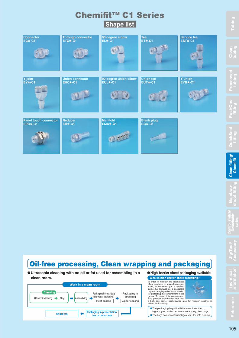
Tub
ing
Cle
an
tub
ing
Pu
sh
On
efi
ttin
gQ
uic
kS
ea
lfi
ttin
gB
amb
oo
-sh
oo
t fi
ttin
gC
ontr
ol s
witc
h/D
etac
habl
ese
ries
Cle
an f
itti
ng
/C
hem
ifit
Jig
/To
ol/
Accesso
ryR
efer
ence
Pro
cess
edtu
bin
gTe
chn
ical
info
rmat
ion
ConnectorEC*-C1
Through connectorETC*-C1
90 degree elbowEL*-C1
TeeET*-C1
Service teeEST*-C1
Y jointEY*-C1
Union connectorEUC*-C1
90 degree union elbowEUL*-C1
Union teeEUT*-C1
Y unionEYB*-C1
Panel touch connectorEPC*-C1
ReducerER*-C1
ManifoldEMA*-C1
Blank plugBC*-C1
ChemitTM C1 SeriesShape list
105
Oil-free processing, Clean wrapping and packagingUltrasonic cleaning with no oil or fat used for assembling in a
clean room.High-barrier sheet packaging available
Work in a clean room
What is high-barrier sheet packaging?
Cleaning
Shipping
Ultrasonic cleaning
Packaging in small bag(individual packaging)
Heat sealing
Packaging inlarge bag
Zipper sealingDry Assembling
Packaging in presentationbox or outer case
In order to maintain the cleanliness of our products, no space for oxygen, water, or corrosive gas is allowed inside the package so a packaging bag with a high gas barrier is needed for protecting the content from these gases. To meet this requirement, Nitta provides high-barrier bags with a high gas barrier performance also for nitrogen sealing or atmospheric sealing.
The packaging bags that Nitta uses have thehighest gas barrier performance among clear bags.
The bags do not contain halogen, etc., for safe burning.

Tub
ing
Cle
an
tub
ing
Pu
sh
On
efi
ttin
gQ
uic
kS
ea
lfi
ttin
gB
amb
oo
-sh
oo
t fi
ttin
gC
ontr
ol s
witc
h/D
etac
habl
ese
ries
Cle
an f
itti
ng
/C
hem
ifit
Jig
/To
ol/
Accesso
ryR
efer
ence
Pro
cess
edtu
bin
gTe
chn
ical
info
rmat
ion
Through connector
ConnectorMillimeter size type
Inch size type
EC4-R1/8-C1
EC4-R1/4-C1
EC6-R1/8-C1
EC6-R1/4-C1
EC8-R1/8-C1
EC8-R1/4-C1
EC10-R1/4-C1
EC10-R3/8-C1
EC10-R1/2-C1
EC12-R3/8-C1
EC12-R1/2-C1
EC6-N1/8-C1
EC6-N1/4-C1
EC10-N1/4-C1
4
4
6
6
8
8
10
10
10
12
12
6
6
10
R1/8
R1/4
R1/8
R1/4
R1/8
R1/4
R1/4
R3/8
R1/2
R3/8
R1/2
NPT1/8
NPT1/4
NPT1/4
21.9
24.9
23.6
26.6
28.6
27.6
33.2
32.4
35.4
33.4
35.4
23.6
26.6
33.2
14
14
15
15
16
16
19
19
19
20
20
15
15
19
12.0×13.0
14.0×15.4
14.0×15.4
14.0×15.4
17.0×18.5
17.0×18.5
19.0×21.0
19.0×21.0
22.0×24.5
22.0×24.5
22.0×24.5
14.0×15.4
14.0×15.4
19.0×21.0
2.5
2.5
4.0
4.0
6.0
6.0
8.0
8.0
10.0
10.0
10.0
4.0
4.0
8.0
2.0
2.0
2.0
3.0
4.0
4.0
7.0
7.0
—
9.0
11.0
2.0
3.0
7.0
9.0
12.0
9.0
12.0
9.0
12.0
12.0
14.0
16.0
14.0
16.0
9.0
12.0
12.0
10.0
10.0
13.0
13.0
15.0
15.0
18.0
18.0
18.0
21.0
21.0
13.0
13.0
18.0
4.0
4.0
10.5
10.5
20.0
25.0
40.0
40.0
—
50.0
50.0
10.5
10.5
40.0
EC1/4-R1/8-C1
EC1/4-R1/4-C1
EC3/8-R1/4-C1
EC3/8-R3/8-C1
EC1/2-R3/8-C1
EC1/2-R1/2-C1
1/4
1/4
3/8
3/8
1/2
1/2
R1/8
R1/4
R1/4
R3/8
R3/8
R1/2
24.6
27.6
34.0
33.2
35.4
37.4
16
16
20
20
23
23
14.0×15.4
14.0×15.4
19.0×21.0
19.0×21.0
22.0×24.5
22.0×24.5
4.0
4.0
8.0
8.0
10.0
10.0
2.0
3.0
7.0
7.0
9.0
10.0
9.0
12.0
12.0
14.0
14.0
16.0
13.0
13.0
18.0
18.0
21.5
21.5
12.0
12.0
35.0
35.0
66.5
66.5
Millimeter size type
A tubing can be inserted completely through the connector.
ETC4-R1/8-C1
ETC4-R1/4-C1
ETC6-R1/4-C1
ETC8-R1/4-C1
ETC10-R3/8-C1
ETC12-R1/2-C1
4
4
6
8
10
12
R1/8
R1/4
R1/4
R1/4
R3/8
R1/2
21.9
24.9
26.6
27.6
32.4
35.4
12.0×13.0
14.0×15.4
14.0×15.4
17.0×18.5
19.0×21.0
22.0×24.5
4.2
4.2
6.5
8.2
10.2
12.3
9.0
12.0
12.0
12.0
14.0
16.0
10.0
10.0
13.0
15.0
18.0
21.0
2.0
2.0
3.0
4.0
7.0
10.0
Applicabletubing outer
diameter(mm)
TThread
size(R)
FTubing insertion
length(mm)
H×φWidth
across flat(mm)
Weight
(g)
Effective sectional
area(mm2)
Product number D
(mm)
d1
(mm)
L
(mm)
A
(mm)
Applicabletubing outer
diameter(mm)
TThread
size(R)
H×φWidth
across flat(mm)
Weight
(g)
Product number D
(mm)
d1
(mm)
L
(mm)
A
(mm)
Applicabletubing outer
diameter(inch)
TThread
size(R)
FTubing insertion
length(mm)
H×φWidth
across flat(mm)
Weight
(g)
Effective sectional
area(mm2)
Product number D
(mm)
d1
(mm)
L
(mm)
A
(mm)
106
φD
L
H×φA
T
φd1
ChemifitTM C1 Series
F
φd1
T
LA H×φ
φD

Tub
ing
Cle
an
tub
ing
Pu
sh
On
efi
ttin
gQ
uic
kS
ea
lfi
ttin
gB
amb
oo
-sh
oo
t fi
ttin
gC
ontr
ol s
witc
h/D
etac
habl
ese
ries
Cle
an f
itti
ng
/C
hem
ifit
Jig
/To
ol/
Accesso
ryR
efer
ence
Pro
cess
edtu
bin
gTe
chn
ical
info
rmat
ion
90 degree elbow
Tee
Millimeter size type
Inch size type
EL4-R1/8-C1
EL4-R1/4-C1
EL6-R1/8-C1
EL6-R1/4-C1
EL8-R1/8-C1
EL8-R1/4-C1
EL10-R1/4-C1
EL10-R3/8-C1
EL12-R3/8-C1
EL12-R1/2-C1
EL6-N1/8-C1
EL6-N1/4-C1
4
4
6
6
8
8
10
10
12
12
6
6
R1/8
R1/4
R1/8
R1/4
R1/8
R1/4
R1/4
R3/8
R3/8
R1/2
NPT1/8
NPT1/4
17.7
17.7
18.9
18.9
21.1
21.1
25.0
25.0
26.7
26.7
18.9
18.9
9.0
12.0
9.0
12.0
9.0
12.0
12.0
14.0
14.0
16.0
9.0
12.0
14
14
15
15
16
16
19
19
20
20
15
15
10.0×11.0
14.0×15.4
12.0×13.0
14.0×15.4
14.0×15.4
14.0×15.4
17.0×18.5
17.0×18.5
19.0×21.0
22.0×24.0
12.0×13.0
14.0×15.4
3.0
3.0
4.5
4.5
6.0
6.5
8.0
8.0
10.0
9.5
4.5
4.5
2.0
3.0
4.0
4.0
5.0
6.0
9.0
11.0
13.0
15.0
4.0
4.0
23.7
27.7
26.2
30.2
29.2
31.2
37.2
37.2
38.7
41.7
26.2
30.2
23.2
25.4
25.4
26.6
28.8
28.8
34.3
34.3
37.2
38.7
25.4
26.6
28.7
32.7
32.7
36.7
36.7
38.9
46.2
46.2
49.0
52.0
32.7
36.7
5.0
7.0
4.5
7.0
6.0
6.5
8.0
9.0
10.0
12.0
4.5
7.0
10.0
10.0
13.0
13.0
15.0
15.0
18.0
18.0
20.5
20.5
13.0
13.0
4.0
4.0
12.0
12.0
18.5
23.0
34.5
37.0
43.0
43.0
12.0
12.0
EL1/4-R1/8-C1
EL1/4-R1/4-C1
EL3/8-R1/4-C1
EL3/8-R3/8-C1
EL1/2-R3/8-C1
EL1/2-R1/2-C1
1/4
1/4
3/8
3/8
1/2
1/2
R1/8
R1/4
R1/4
R3/8
R3/8
R1/2
19.9
19.9
25.8
25.8
28.7
28.7
9.0
12.0
12.0
14.0
14.0
16.0
16
16
20
20
23
23
12.0×13.0
14.0×15.4
17.0×18.5
17.0×18.5
19.0×21.0
22.0×24.0
4.5
4.5
8.0
8.0
10.0
9.5
4.0
4.0
9.0
11.0
13.0
15.0
26.2
30.2
37.2
37.2
38.7
41.7
26.4
27.6
35.1
35.1
39.2
40.7
32.7
36.7
46.2
46.2
49.5
52.5
4.5
7.0
8.0
9.0
10.0
12.0
13.0
13.0
18.0
18.0
21.5
21.5
13.0
13.0
30.0
32.0
53.0
55.5
Millimeter size type
Inch size type
9.0
12.0
9.0
12.0
9.0
12.0
12.0
14.0
14.0
16.0
9.0
12.0
14
14
15
15
16
16
19
19
20
20
15
15
10.0×11.0
14.0×15.4
12.0×13.0
14.0×15.4
14.0×15.4
14.0×15.4
17.0×18.5
17.0×18.5
19.0×21.0
22.0×24.0
12.0×13.0
14.0×15.4
3.0
3.0
4.5
4.5
6.0
6.5
8.0
8.0
10.0
9.5
4.5
4.5
3.0
4.0
5.0
6.0
7.0
8.0
14.0
16.0
19.0
21.0
5.0
6.0
23.7
27.7
26.2
30.2
29.2
31.2
37.2
37.2
38.7
41.7
26.2
30.2
35.3
35.3
37.9
37.9
42.2
42.2
50.0
50.0
53.4
53.4
37.9
37.9
5.0
7.0
4.5
7.0
6.0
6.5
8.0
9.0
10.0
12.0
4.5
7.0
10.0
10.0
13.0
13.0
15.0
15.0
18.0
18.0
20.5
20.5
13.0
13.0
28.7
32.7
32.7
36.7
36.7
38.7
46.2
46.2
49.0
52.0
32.7
36.7
ET4-R1/8-C1
ET4-R1/4-C1
ET6-R1/8-C1
ET6-R1/4-C1
ET8-R1/8-C1
ET8-R1/4-C1
ET10-R1/4-C1
ET10-R3/8-C1
ET12-R3/8-C1
ET12-R1/2-C1
ET6-N1/8-C1
ET6-N1/4-C1
4
4
6
6
8
8
10
10
12
12
6
6
R1/8
R1/4
R1/8
R1/4
R1/8
R1/4
R1/4
R3/8
R3/8
R1/2
NPT1/8
NPT1/4
17.7
17.7
18.9
18.9
21.1
21.1
25.0
25.0
26.7
26.7
18.9
18.9
4.0
4.0
12.0
12.0
18.5
23.0
34.5
37.0
43.0
43.0
12.0
12.0
ET1/4-R1/8-C1
ET1/4-R1/4-C1
ET3/8-R1/4-C1
ET3/8-R3/8-C1
ET1/2-R3/8-C1
ET1/2-R1/2-C1
1/4
1/4
3/8
3/8
1/2
1/2
R1/8
R1/4
R1/4
R3/8
R3/8
R1/2
19.9
19.9
25.8
25.8
29.7
29.7
9.0
12.0
12.0
14.0
14.0
16.0
16
16
20
20
23
23
12.0×13.0
14.0×15.4
17.0×18.5
17.0×18.5
19.0×21.0
22.0×24.0
4.5
4.5
8.0
8.0
10.0
9.5
5.0
6.0
14.0
16.0
19.0
21.0
26.2
30.2
37.2
37.2
39.0
42.0
39.8
39.8
51.6
51.6
59.5
59.5
4.5
7.0
8.0
9.0
10.0
12.0
13.0
13.0
18.0
18.0
21.5
21.5
32.7
36.7
46.2
46.2
49.8
52.8
13.0
13.0
30.0
32.0
53.0
55.5
Applicabletubing outer
diameter(mm)
TThread
size(R)
FTubing
insertionlength(mm)
Min. inner
diameter(mm)
H×φWidth
across flat(mm)
Weight
(g)
Effective sectional
area(mm2)
Product number D
(mm)
d1
(mm)
L2
(mm)
L1
(mm)
L3
(mm)
L4
(mm)
A
(mm)
Applicabletubing outer
diameter(inch)
TThread
size(R)
FTubing
insertionlength(mm)
Min. inner
diameter(mm)
H×φWidth
across flat(mm)
Weight
(g)
Effective sectional
area(mm2)
Product number D
(mm)
d1
(mm)
L2
(mm)
L1
(mm)
L3
(mm)
L4
(mm)
A
(mm)
Applicabletubing outer
diameter(mm)
TThread
size(R)
FTubing
insertionlength(mm)
Min. inner
diameter(mm)
H×φWidth
across flat(mm)
Weight
(g)
Effective sectional
area(mm2)
Product number D
(mm)
d1
(mm)
L2
(mm)
L1
(mm)
L4
(mm)
L5
(mm)
A
(mm)
Applicabletubing outer
diameter(inch)
TThread
size(R)
FTubing
insertionlength(mm)
Min. inner
diameter(mm)
H×φWidth
across flat(mm)
Weight
(g)
Effective sectional
area(mm2)
Product number D
(mm)
d1
(mm)
L2
(mm)
L1
(mm)
L4
(mm)
L5
(mm)
A
(mm)
107
φD
L3
L1
F
L4L2
φd1 T
H×φA
L5
L1F
φD
L4L2
A
φd1 T
H×φ
ChemifitTM C1 Series

Tub
ing
Cle
an
tub
ing
Pu
sh
On
efi
ttin
gQ
uic
kS
ea
lfi
ttin
gB
amb
oo
-sh
oo
t fi
ttin
gC
ontr
ol s
witc
h/D
etac
habl
ese
ries
Cle
an f
itti
ng
/C
hem
ifit
Jig
/To
ol/
Accesso
ryR
efer
ence
Pro
cess
edtu
bin
gTe
chn
ical
info
rmat
ion
Service tee
Y joint
Inch size type
Millimeter size type
EST4-R1/8-C1
EST4-R1/4-C1
EST6-R1/8-C1
EST6-R1/4-C1
EST8-R1/8-C1
EST8-R1/4-C1
EST10-R1/4-C1
EST10-R3/8-C1
EST12-R3/8-C1
EST12-R1/2-C1
EST6-N1/8-C1
EST6-N1/4-C1
4
4
6
6
8
8
10
10
12
12
6
6
R1/8
R1/4
R1/8
R1/4
R1/8
R1/4
R1/4
R3/8
R3/8
R1/2
NPT1/8
NPT1/4
17.7
17.7
18.9
18.9
21.1
21.1
25.0
25.0
26.7
26.7
18.9
18.9
9.0
12.0
9.0
12.0
9.0
12.0
12.0
14.0
14.0
16.0
9.0
12.0
14
14
15
15
16
16
19
19
20
20
15
15
10.0×11.0
14.0×15.4
12.0×13.0
14.0×15.4
14.0×15.4
14.0×15.4
17.0×18.5
17.0×18.5
19.0×21.0
22.0×24.0
12.0×13.0
14.0×15.4
3.0
3.0
4.5
4.5
6.0
6.5
8.0
8.0
10.0
9.5
4.5
4.5
3.0
4.0
5.0
6.0
7.0
8.0
14.0
16.0
19.0
21.0
5.0
6.0
23.7
27.7
26.2
30.2
29.2
31.2
37.2
37.2
38.7
41.7
26.2
30.2
41.4
45.4
45.1
49.1
50.3
52.3
62.2
62.2
65.4
68.4
45.1
49.1
5.0
7.0
4.5
7.0
6.0
6.5
8.0
9.0
10.0
12.0
4.5
7.0
10.0
10.0
13.0
13.0
15.0
15.0
18.0
18.0
20.5
20.5
13.0
13.0
17.7
17.7
18.9
18.9
21.1
21.1
25.0
25.0
26.7
26.7
18.9
18.9
23.2
25.4
25.4
26.6
28.8
28.8
34.3
34.3
37.2
38.7
25.4
26.6
4.0
4.0
12.0
12.0
18.5
23.0
34.5
37.0
43.0
43.0
12.0
12.0
EST1/4-R1/8-C1
EST1/4-R1/4-C1
EST3/8-R1/4-C1
EST3/8-R3/8-C1
EST1/2-R3/8-C1
EST1/2-R1/2-C1
1/4
1/4
3/8
3/8
1/2
1/2
R1/8
R1/4
R1/4
R3/8
R3/8
R1/2
19.9
19.9
25.8
25.8
29.7
29.7
9.0
12.0
12.0
14.0
14.0
16.0
16
16
20
20
23
23
12.0×13.0
14.0×15.4
17.0×18.5
17.0×18.5
19.0×21.0
22.0×24.0
4.5
4.5
8.0
8.0
10.0
9.5
5.0
6.0
14.0
16.0
19.0
21.0
26.2
30.2
37.2
37.2
39.0
42.0
46.1
50.1
63.0
63.0
68.7
71.7
4.5
7.0
8.0
9.0
10.0
12.0
13.0
13.0
18.0
18.0
21.5
21.5
19.9
19.9
25.8
25.8
29.7
29.7
26.4
27.6
35.1
35.1
40.2
41.7
13.0
13.0
30.0
32.0
53.0
55.5
Inch size type
Millimeter size type
4
4
6
6
8
8
10
10
12
12
6
6
R1/8
R1/4
R1/8
R1/4
R1/8
R1/4
R1/4
R3/8
R3/8
R1/2
NPT1/8
NPT1/4
41.9
45.9
45.2
49.2
50.3
52.3
60.2
60.2
64.2
67.2
45.2
49.2
9.0
12.0
9.0
12.0
9.0
12.0
12.0
14.0
14.0
16.0
9.0
12.0
14
14
15
15
16
16
19
19
20
20
15
15
10.0×11.0
14.0×15.4
12.0×13.0
14.0×15.4
14.0×15.4
14.0×15.4
17.0×18.5
17.0×18.5
19.0×21.0
22.0×24.0
12.0×13.0
14.0×15.4
3.0
3.0
4.5
4.5
6.0
6.5
8.0
8.0
10.0
9.5
4.5
4.5
4.0
5.0
6.0
7.0
8.0
9.0
15.0
16.0
22.0
23.0
6.0
7.0
21.0
21.0
25.2
25.2
29.2
29.2
35.5
35.5
40.5
40.5
25.2
25.2
5.0
7.0
4.5
7.0
6.0
6.5
8.0
9.0
10.0
12.0
4.5
7.0
10.0
10.0
13.0
13.0
15.0
15.0
18.0
18.0
20.5
20.5
13.0
13.0
3.2
3.2
4.2
4.2
4.2
4.2
4.2
4.2
4.2
4.2
4.2
4.2
9.7
9.7
12.5
12.5
14.5
14.5
17.5
17.5
20.0
20.0
12.5
12.5
13.9
13.9
15.2
15.2
16.8
16.8
18.7
18.7
20.7
20.7
15.2
15.2
11.0
11.0
12.2
12.2
14.2
14.2
17.5
17.5
20.0
20.0
12.2
12.2
EY4-R1/8-C1
EY4-R1/4-C1
EY6-R1/8-C1
EY6-R1/4-C1
EY8-R1/8-C1
EY8-R1/4-C1
EY10-R1/4-C1
EY10-R3/8-C1
EY12-R3/8-C1
EY12-R1/2-C1
EY6-N1/8-C1
EY6-N1/4-C1
3.5
3.5
9.0
9.0
17.5
20.0
27.5
28.0
40.0
40.0
9.0
9.0
EY1/4-R1/8-C1
EY1/4-R1/4-C1
EY3/8-R1/4-C1
EY3/8-R3/8-C1
EY1/2-R3/8-C1
EY1/2-R1/2-C1
1/4
1/4
3/8
3/8
1/2
1/2
R1/8
R1/4
R1/4
R3/8
R3/8
R1/2
46.2
50.2
61.0
61.0
67.7
70.7
9.0
12.0
12.0
14.0
14.0
16.0
16
16
20
20
23
23
12.0×13.0
14.0×15.4
17.0×18.5
17.0×18.5
19.0×21.0
22.0×24.0
4.5
4.5
8.0
8.0
10.0
9.5
6.0
7.0
15.0
16.0
22.0
23.0
25.2
25.2
35.5
35.5
42.5
42.5
4.5
7.0
8.0
9.0
10.0
12.0
13.0
13.0
18.0
18.0
21.5
21.5
4.2
4.2
4.2
4.2
4.2
4.2
12.5
12.5
17.5
17.5
21.0
21.0
16.2
16.2
19.5
19.5
22.7
22.7
12.2
12.2
17.5
17.5
21.0
21.0
10.5
10.5
26.0
26.0
48.0
48.0
Applicabletubingouter
diameter(mm)
TThread
size(R)
FTubing
insertionlength(mm)
Min. innerdiameter(mm)
H×φWidthacross
flat(mm)
Weight
(g)
Effectivesectional
area(mm2)
Product number d1
(mm)
L1
(mm)
L2
(mm)
L6
(mm)
L7
(mm)
L8
(mm)
A
(mm)
D
(mm)
Applicabletubingouter
diameter(inch)
TThread
size(R)
FTubing
insertionlength(mm)
Min. innerdiameter(mm)
H×φWidthacross
flat(mm)
Weight
(g)
Effectivesectional
area(mm2)
Product number d1
(mm)
L1
(mm)
L2
(mm)
L6
(mm)
L7
(mm)
L8
(mm)
A
(mm)
D
(mm)
Applicabletubing outer
diameter(mm)
TThread
size(R)
FTubinginsertionlength(mm)
H×φWidthacross
flat(mm)
Weight
(g)
Effectivesectional
area(mm2)
Product number D
(mm)
W
(mm)
d2
(mm)
d1
(mm)
P3
(mm)
P4
(mm)
Min.inner
diameter(mm)
L
(mm)
L11
(mm)
A
(mm)
Applicabletubing outer
diameter(inch)
TThread
size(R)
FTubinginsertionlength(mm)
H×φWidthacross
flat(mm)
Weight
(g)
Effectivesectional
area(mm2)
Product number D
(mm)
W
(mm)
d2
(mm)
d1
(mm)
P3
(mm)
P4
(mm)
Min.inner
diameter(mm)
L
(mm)
L11
(mm)
A
(mm)
108
φD
φd1
L6L8
T
H×φ
AL2
FL1
L7
φD
W
L11
φd2
P4
F
H×φ
T
φd1
A
L
P3
ChemifitTM C1 Series

Tub
ing
Cle
an
tub
ing
Pu
sh
On
efi
ttin
gQ
uic
kS
ea
lfi
ttin
gB
amb
oo
-sh
oo
t fi
ttin
gC
ontr
ol s
witc
h/D
etac
habl
ese
ries
Cle
an f
itti
ng
/C
hem
ifit
Jig
/To
ol/
Accesso
ryR
efer
ence
Pro
cess
edtu
bin
gTe
chn
ical
info
rmat
ion
Union connector
90 degree union elbow
Millimeter size type
Inch size type
Millimeter size type
Inch size type (different diameter connection)
Inch size — millimeter size connection
EUC3-C1
EUC4-C1
EUC6-C1
EUC8-C1
EUC10-C1
EUC12-C1
3
4
6
8
10
12
3
4
6
8
10
12
23.2
32.7
34.5
36.6
42.4
44.4
11
14
15
16
19
20
3.2
4.2
4.2
4.2
4.2
4.2
6.3
10.0
13.0
15.0
18.0
20.5
2.0
3.0
5.0
7.0
9.0
11.0
—
2.0
4.0
5.0
10.0
14.0
11.6
16.4
17.2
18.3
21.2
22.2
3.6
5.0
6.0
7.0
8.5
9.8
11
14
15
16
19
20
6.0
9.7
12.5
14.5
17.5
20.0
6.3
10.0
13.0
15.0
18.0
20.5
2.5
3.5
12.5
28.0
45.0
67.0
EUC1/8-C1
EUC1/4-C1
EUC3/8-C1
EUC1/2-C1
1/8
1/4
3/8
1/2
1/8
1/4
3/8
1/2
25.9
36.4
44.0
48.5
12
16
20
23
3.2
4.2
4.2
4.2
8.0
13.0
18.0
21.5
2.5
5.0
9.0
11.0
—
4.0
10.0
19.0
13.0
18.2
22.0
24.2
4.5
6.0
8.5
10.3
12
16
20
23
8.0
12.5
17.5
20.0
8.0
13.0
18.0
21.5
—
12.5
28.0
35.0
EUC1/8-1/4-C1
EUC1/4-3/8-C1
EUC3/8-1/2-C1
1/8
1/4
3/8
1/4
3/8
1/2
34.4
40.7
46.2
16
20
23
4.2
4.2
4.2
10.0
15.0
18.0
2.5
5.0
9.0
—
—
—
18.2
22.0
24.2
6.0
8.5
9.8
12
16
20
12.5
17.5
20.0
13.0
18.0
21.5
—
—
—
EUC1/4-6-C1
EUC3/8-10-C1
1/4
3/8
6
10
35.4
43.2
15
19
4.2
4.2
13.0
18.0
5.0
9.0
4.0
10.0
17.2
21.2
6.0
8.5
16
20
12.5
17.5
13.0
18.0
12.5
45.0
d1Applicable
tubing outerdiameter(mm)
d2Applicable
tubing outerdiameter(mm)
F1Tubing
insertion length(mm)
F2Tubing
insertion length(mm)
Min. innerdiameter
(mm)
Weight
(g)
Effectivesectional
area(mm2)
Product number L
(mm)
L1
(mm)
P1
(mm)
W
(mm)
D2
(mm)
D1
(mm)
d3
(mm)
d1Applicable
tubing outerdiameter(inch)
d2Applicable
tubing outerdiameter(inch)
F1Tubing
insertion length(mm)
F2Tubing
insertion length(mm)
Min. innerdiameter
(mm)
Weight
(g)
Effectivesectional
area(mm2)
Product number L
(mm)
L1
(mm)
P1
(mm)
W
(mm)
D2
(mm)
D1
(mm)
d3
(mm)
d1Applicable
tubing outerdiameter(inch)
d2Applicable
tubing outerdiameter(inch)
F1Tubing
insertion length(mm)
F2Tubing
insertion length(mm)
Min. innerdiameter
(mm)
Weight
(g)
Effectivesectional
area(mm2)
Product number L
(mm)
L1
(mm)
P1
(mm)
W
(mm)
D2
(mm)
D1
(mm)
d3
(mm)
d1Applicable
tubing outerdiameter(inch)
d2Applicable
tubing outerdiameter(mm)
F1Tubing
insertion length(mm)
F2Tubing
insertion length(mm)
Min. innerdiameter
(mm)
Weight
(g)
Effectivesectional
area(mm2)
Product number L
(mm)
L1
(mm)
P1
(mm)
W
(mm)
D2
(mm)
D1
(mm)
d3
(mm)
Inch size type
EUL3-C1
EUL4-C1
EUL6-C1
EUL8-C1
EUL10-C1
EUL12-C1
3
4
6
8
10
12
Applicabletubing outer
diameter(mm)
Product number
12.6
17.7
18.9
21.1
25.0
26.7
11
14
15
16
19
20
2.0
3.0
5.0
7.0
9.0
11.0
−
3.0
4.0
6.0
12.0
16.0
15.7
22.7
25.4
28.6
34.0
37.0
Min. innerdiameter
(mm)
FTubing insertion
length(mm)
Weight
(g)
L8
(mm)
L1
(mm)6
9.7
12.5
14.5
17.5
20.0
W
(mm)6.3
10.0
13.0
15.0
18.0
20.5
D
(mm)4.1
6.9
8.3
9.3
10.8
12.1
P1
(mm)
Effectivesectional
area(mm2)
EUL1/8-C1
EUL1/4-C1
EUL3/8-C1
EUL1/2-C1
1/8
1/4
3/8
1/2
Applicabletubing outer
diameter(mm)
Product number
15.2
19.9
25.8
29.7
12
16
20
23
3.0
5.0
9.0
11.0
−
4.0
12.0
20.0
19.2
26.4
34.8
40.5
Min. innerdiameter
(mm)
FTubing insertion
length(mm)
Weight
(g)
L8
(mm)
L1
(mm)8.0
12.5
17.5
21.0
W
(mm)8.0
13.0
18.0
21.5
D
(mm)5.0
8.3
10.8
12.6
P1
(mm)
3.2
4.2
4.2
4.2
4.2
4.2
d3
(mm)
3.2
4.2
4.2
4.2
d3
(mm)
Effectivesectional
area(mm2)
−
12.0
27.0
54.5
2.0
3.5
9.5
19.5
32.5
45.5
109
L8
L1
F
φD
d3
L8 P1
W
F1
L1
L
W
F2
φD1
P1φd
1
φD2
φd2
φd3
ChemifitTM C1 Series

Tub
ing
Cle
an
tub
ing
Pu
sh
On
efi
ttin
gQ
uic
kS
ea
lfi
ttin
gB
amb
oo
-sh
oo
t fi
ttin
gC
ontr
ol s
witc
h/D
etac
habl
ese
ries
Cle
an f
itti
ng
/C
hem
ifit
Jig
/To
ol/
Accesso
ryR
efer
ence
Pro
cess
edtu
bin
gTe
chn
ical
info
rmat
ion
Union tee
Panel touch connector
Y union
Inch size type
Millimeter size type
Millimeter size type
Inch size type
Inch size type
Millimeter size type
EUT3-C1
EUT4-C1
EUT6-C1
EUT8-C1
EUT10-C1
EUT12-C1
3
4
6
8
10
12
12.6
17.7
18.9
21.1
25.0
26.7
11
14
15
16
19
20
2.0
3.0
5.0
7.0
9.0
11.0
1.5
4.0
7.0
9.0
17.0
23.0
25.1
35.3
37.9
42.2
50.0
53.4
6
9.7
12.5
14.5
17.5
20.0
6.3
10.0
13.0
15.0
18.0
20.5
4.1
6.9
8.3
9.3
10.8
12.1
8.2
14.0
17.0
19.0
22.0
24.0
12.6
17.7
18.9
21.1
25.0
26.7
15.7
22.7
25.4
28.6
34.0
37.0
3.5
9.5
19.5
32.5
45.5
EUT1/8-C1
EUT1/4-C1
EUT3/8-C1
EUT1/2-C1
1/8
1/4
3/8
1/2
15.2
19.9
25.8
29.7
12
16
20
23
3.0
5.0
9.0
11.0
—
7.0
17.0
29.0
30.4
39.8
51.6
59.5
8.0
12.5
17.5
21.0
8.0
13.0
18.0
21.5
3.2
4.2
4.2
4.2
4.2
4.2
3.2
4.2
4.2
4.2
5.0
8.3
10.8
12.6
10.0
17.0
22.0
25.0
15.2
19.9
25.8
29.7
19.2
26.4
34.8
40.5
—
12.0
27.0
54.5
EYB3-C1
EYB4-C1
EYB6-C1
EYB8-C1
EYB10-C1
EYB12-C1
3
4
6
8
10
12
25.7
34.7
38.4
43.7
49.0
54.8
11
14
15
16
19
20
2.0
3.0
5.0
7.0
9.0
11.0
—
4.0
6.0
9.0
17.0
24.0
13.3
21.0
25.2
29.2
35.5
40.5
6.0
9.7
12.5
14.5
17.5
20.0
6.3
10.0
13.0
15.0
18.0
20.5
10.9
13.9
15.2
16.8
18.7
20.7
7.0
11.0
12.2
14.2
17.5
20.0
2.0
3.2
4.2
4.2
4.2
4.2
2
3.0
8.0
18.0
27.0
38.5
EYB1/8-C1
EYB1/4-C1
EYB3/8-C1
EYB1/2-C1
1/8
1/4
3/8
1/2
29.4
40.3
50.6
60.4
12
16
20
23
3.0
5.0
9.0
11.0
—
10.0
24.0
33.0
17.0
25.2
35.5
42.5
8.0
12.5
17.5
21.0
8.0
13.0
18.0
21.5
11.7
16.2
19.5
22.7
9.0
12.2
17.5
21.0
3.2
4.2
4.2
4.2
—
10.5
24.0
46.5
EPC4-C1
EPC6-C1
EPC8-C1
EPC10-C1
EPC12-C1
4
6
8
10
12
32.7
34.5
36.6
42.4
44.4
14
15
16
19
20
7.5
9.5
10.0
14.0
16.0
17.0
19.0
22.0
27.0
30.0
13
15
17
21
23
3.0
5.0
7.0
9.0
11.0
5.0
7.0
9.0
16.0
67.0
24.0
28.0
30.0
37.0
39.0
2.5
2.5
3.0
3.0
3.0
3.5
12.5
28.0
45.0
67.0
EPC1/4-C1
EPC3/8-C1
EPC1/2-C1
*Made to order
1/4
3/8
1/2
36.4
44.0
48.5
16
20
23
9.5
14.0
16.0
19.0
27.0
30.0
7.0
16.0
67.0
28.0
37.0
39.0
2.5
3.0
3.0
5.0
9.0
10. 0
12.5
45.0
67.0
15
21
23
2.0
Applicabletubing outer
diameter(mm)
Min. innerdiameter
(mm)
FTubing
insertionlength(mm)
Weight
(g)
Effectivesectional
area(mm2)
Product number W
(mm)
d2
(mm)
L1
(mm)
P1
(mm)
P2
(mm)
L5
(mm)
L6
(mm)
L8
(mm)
D
(mm)
Applicabletubing outer
diameter(inch)
Min. innerdiameter
(mm)
FTubing
insertionlength(mm)
Weight
(g)
Effectivesectional
area(mm2)
Product number W
(mm)
d2
(mm)
L1
(mm)
P1
(mm)
P2
(mm)
L5
(mm)
L6
(mm)
L8
(mm)
D
(mm)
Applicabletubing outer
diameter(mm)
tMax. panelthickness
(mm)
T1Recommended
panel holediameter(mm)
FTubing
insertionlength(mm)
Washerouter
diameter(mm)
Washerthickness
(mm)
Min. innerdiameter
(mm)
Weight
(g)
Effectivesectional
area(mm2)
Product number L
(mm)
H4
(mm)
Applicabletubing outer
diameter(inch)
tMax. panelthickness
(mm)
T1Recommended
panel holediameter(mm)
FTubing
insertionlength(mm)
Washerouter
diameter(mm)
Washerthickness
(mm)
Min. innerdiameter
(mm)
Weight
(g)
Effectivesectional
area(mm2)
Product number L
(mm)
H4
(mm)
Applicabletubing outer
diameter(mm)
FTubing
insertionlength(mm)
Weight
(g)
Effectivesectional
area(mm2)
Product number W
(mm)
P3
(mm)
D
(mm)
P4
(mm)
d2
(mm)
Min. innerdiameter
(mm)
L
(mm)
L11
(mm)
Applicabletubing outer
diameter(inch)
FTubing
insertionlength(mm)
Weight
(g)
Effectivesectional
area(mm2)
Product number W
(mm)
P3
(mm)
D
(mm)
P4
(mm)
d2
(mm)
Min. innerdiameter
(mm)
L
(mm)
L11
(mm)
110
ChemifitTM C1 Series
W
φD
φD
P4
L11
φd2
P3 F
F
L
T1 F
t H4
L
H4
L5
L1F
φD
L 8L6
P2
P1
W
φd2
*

Tub
ing
Cle
an
tub
ing
Pu
sh
On
efi
ttin
gQ
uic
kS
ea
lfi
ttin
gB
amb
oo
-sh
oo
t fi
ttin
gC
ontr
ol s
witc
h/D
etac
habl
ese
ries
Cle
an f
itti
ng
/C
hem
ifit
Jig
/To
ol/
Accesso
ryR
efer
ence
Pro
cess
edtu
bin
gTe
chn
ical
info
rmat
ion
Reducer
Inch size type
Millimeter size type
ER4-6-C1
ER4-8-C1
ER6-8-C1
ER6-10-C1
ER8-10-C1
ER8-12-C1
ER10-12-C1
4
4
6
6
8
8
10
6
8
8
10
10
12
12
14
14
15
15
16
16
19
3.0
3.0
5.0
5.0
7.0
7.0
9.0
2.0
2.0
2.0
3.0
3.0
4.0
8.0
34.5
32.0
34.7
35.6
39.4
38.3
42.8
10.0
10.0
13.0
13.0
15.0
15.0
18.0
18.0
18.8
17.7
20.6
18.9
16.3
20.8
3.5
3.5
10.5
10.5
28.0
28.0
45.0
ER1/4-3/8-C1 1/4 3/8 16 5.0 3.035.2 13.016.4 12.0
Manifold
Blank plugMillimeter size type
Inch size type
Inch size type
EMA1/8-1/4-4S-C1 1/8 1/4 12 16 12.665.7 8.09.0 21.7 13.0 —
BC3-C1
BC4-C1
BC6-C1
BC8-C1
BC10-C1
BC12-C1
3
4
6
8
10
12
23.5
28.0
28.0
29.0
32.0
34.0
0.5
0.5
0.8
1.1
1.6
2.4
5.0
7.7
9.7
11.7
14.0
16.0
13.0
15.5
16.0
16.0
17.7
20.4
BC1/8-C1
BC1/4-C1
BC3/8-C1
BC1/2-C1
1/8
1/4
3/8
1/2
26.0
28.0
32.0
34.0
—
1.2
2.5
3.8
7.7
9.7
14.0
16.0
13.5
16.0
17.7
20.4
D1
Insertion part diameter(mm)
Weight
(g)Product number D
(mm)
L
(mm)
L1
(mm)
D1
Insertion part diameter(inch)
Weight
(g)Product number D
(mm)
L
(mm)
L1
(mm)
Applicabletubing outer
diameter(mm)
D1Insertion part
diameter(mm)
FTubing insertion
length(mm)
Weight
(g)
Effectivesectional
area(mm2)
Product number D
(mm)
Min. innerdiameter
(mm)
L
(mm)
L10
(mm)
Applicabletubing outer
diameter(inch)
D1Insertion part
diameter(inch)
FTubing insertion
length(mm)
Weight
(g)
Effectivesectional
area(mm2)
Product number D
(mm)
Min. innerdiameter
(mm)
L
(mm)
L10
(mm)
d1Applicable
tubing outerdiameter
(inch)
d2Applicable
tubing outerdiameter
(inch)
F2Tubing
insertionlength(mm)
F1Tubing
insertionlength(mm)
Weight
(g)
Product number D1
(mm)
D2
(mm)
W
(mm)
L
(mm)
L8
(mm)
P1
(mm)
111
ChemifitTM C1 Series
φD1
φD
LL10
F
φD1
L
L1
φD
P1φD1
F2
W
L
d1
φD2 L8
F1
d2
φ3.2

Tub
ing
Cle
an
tub
ing
Pu
sh
On
efi
ttin
gQ
uic
kS
ea
lfi
ttin
gB
amb
oo
-sh
oo
t fi
ttin
gC
ontr
ol s
witc
h/D
etac
habl
ese
ries
Cle
an f
itti
ng
/C
hem
ifit
Jig
/To
ol/
Accesso
ryR
efer
ence
Pro
cess
edtu
bin
gTe
chn
ical
info
rmat
ion
ChemifitTM Series
Handling instructions
Operating fluid, working temperature range
Pressure condition
Cross-sectional structure diagram
Features
Polyurethane tubingPolyolefin resin tubing Fluorocarbon resin tubing
ChemitTM C1S Series
Made in oil-free processAssembled after cleaning each part in a clean room. No oil or fat is used in the sealing materials.
PushOne connection of tubingThe tubes can be connected without using a jig or tools.
SUS304 threadHigh thread strength.
Double clean packageEach fitting is packed in a clean room and put in a zipper sealed bag.
Easy directional setting of tubingThe direction of elbows, tees, etc., can be decided at the time of piping installation.
Maximum working pressure:0.7MPa(at20°C)Negative pressure performance:−99.975kPa
Reference
PushOneTM fitting for clean air, pure water and chemical liquids
Clean-consciousproduct
Applicable tubing Related products and product introduction
(*1) Combinatory use of U2 or U1 tubing and Chemifit C1S series mixes general and clean type performances. When using them together in a clean environment, be aware of how this could lower the cleanliness level.
Contact us for various chemical liquids.
See “Combination List of Tubing and Fitting” on page 8.
10.90.80.70.60.50.40.30.20.1
0—20 0
Working temperature (°C)
Max
imum
wor
king
pres
sure
chan
ge (M
Pa)
20 40 60 80
Body (special polypropylene resin)Tubing seal (EPDM)
Back ring (special polypropylene resin)
Lock ring (SUS301)
Collar (SUS304)
Release sleeve (special polypropylene resin)
Clean tubing
O ring (EPDM)
Adapter (SUS304)
*1
Operating fluid Working temperature range
Air (clean air) −20°C∼+80°C
Water (pure water) 0°C∼+80°C
Relation between the working temperature and the maximum working pressure
Maximum working pressure varies with working temperature (environmental temperature). For use at an abnormal temperature, always check the maximum working pressure change in the graph below and keep pressure within the range.
See page 34 for the common handling instructions for fittings.
When the working conditions of tubes and fittings differ, use them under the lower specified conditions.
When water is used as the operating fluid, do not allow it to freeze.
Do not bend the pipe sharply near the tubing insertion port (sleeve end) of the fitting. Keep the tubing straight for twice as long as the tubing diameter from the insertion port.
Caution:
Caution:
Caution:
Instruction manual ·······P.176Chemical resistance specification table ········P.198Effective sectional area ··P.168Negative-pressure performance list ··········P.169
U2 U1TA TPPL PN
112
The tubing size is shown on the release sleeve.
Product number example Distinction of millimeter/inch sizes
Off toolChemifit C1
speed controller
EL 6 - R1/4 - C1S
Shape
Applicable tubing outer diameter
Chemifit C1S series
Thread size

Tub
ing
Cle
an
tub
ing
Pu
sh
On
efi
ttin
gQ
uic
kS
ea
lfi
ttin
gB
amb
oo
-sh
oo
t fi
ttin
gC
ontr
ol s
witc
h/D
etac
habl
ese
ries
Cle
an f
itti
ng
/C
hem
ifit
Jig
/To
ol/
Accesso
ryR
efer
ence
Pro
cess
edtu
bin
gTe
chn
ical
info
rmat
ion
ChemitTM C1S SeriesShape list
See Chemifit C1 series for union type shape.
ConnectorEC*-C1S
Internal connectorEFC*-C1S
Y jointEY*-C1S
Panel touch connectorEPC*-C1S
90 degree elbowEL*-C1S
TeeET*-C1S
Service teeEST*-C1S
113
Oil-free processing, Clean wrapping and packagingUltrasonic cleaning with no oil or fat used for assembling in a
clean room.High-barrier sheet packaging available
Work in a clean room
What is high-barrier sheet packaging?
Shipping
Packaging in small bag(individual packaging)
Heat sealing
Packaging inlarge bag
Zipper sealing
Packaging in presentationbox or outer case
The packaging bags that Nitta uses have thehighest gas barrier performance among clear bags.
The bags do not contain halogen, etc., for safe burning.
Cleaning
Ultrasonic cleaning Dry Assembling
In order to maintain the cleanliness of our products, no space for oxygen, water, or corrosive gas is allowed inside the package so a packaging bag with a high gas barrier is needed for protecting the content from these gases. To meet this requirement, Nitta provides high-barrier bags with a high gas barrier performance also for nitrogen sealing or atmospheric sealing.

Tub
ing
Cle
an
tub
ing
Pu
sh
On
efi
ttin
gQ
uic
kS
ea
lfi
ttin
gB
amb
oo
-sh
oo
t fi
ttin
gC
ontr
ol s
witc
h/D
etac
habl
ese
ries
Cle
an f
itti
ng
/C
hem
ifit
Jig
/To
ol/
Accesso
ryR
efer
ence
Pro
cess
edtu
bin
gTe
chn
ical
info
rmat
ion
Connector
90 degree elbow
Millimeter size type
Internal connectorMillimeter size type
Millimeter size type
Inch size type
Inch size type
EC3-M5-C1S
EC4-M5-C1S
EC4-R1/8-C1S
EC6-M5-C1S
EC6-R1/8-C1S
EC6-R1/4-C1S
EC8-R1/8-C1S
EC8-R1/4-C1S
EC10-R1/4-C1S
EC10-R3/8-C1S
EC12-R3/8-C1S
EC12-R1/2-C1S
3
4
4
6
6
6
8
8
10
10
12
12
M5×0.8
M5×0.8
R1/8
M5×0.8
R1/8
R1/4
R1/8
R1/4
R1/4
R3/8
R3/8
R1/2
15.9
19.4
19.4
23.2
21.6
24.6
28.2
25.2
28.1
29.1
30.0
33.0
11
14
14
15
15
15
16
16
19
19
20
20
7.0×7.7
10.0×11.0
10.0×11.0
12.0×13.0
12.0×13.0
14.0×15.4
14.0×15.4
14.0×15.4
17.0×18.5
17.0×18.5
19.0×21.0
22.0×24.0
2.0
2.0
2.5
2.0
4.0
4.0
6.0
6.0
8.0
8.0
10.0
10.0
2.0
6.0
7.0
9.0
9.0
18.0
14.0
16.0
21.0
29.0
31.0
58.0
3.5
4.0
8.0
4.0
8.0
11.0
9.0
11.0
11.0
12.0
12.0
15.0
5.5
10.0
10.0
12.0
12.0
12.0
13.9
13.9
16.9
16.9
19.0
19.0
2.0
3.0
4.0
3.5
10.5
10.5
20.0
25.0
40.0
40.0
50.0
50.0
EC1/8-M5-C1S 1/8 M5×0.8 16.2 11 8.0×8.8 2.5 —3.5 8 —
EFC4-R1/8-C1S
EFC6-R1/8-C1S
EFC6-R1/4-C1S
EFC8-R1/4-C1S
EFC10-R1/4-C1S
EFC10-R3/8-C1S
EFC10-R1/2-C1S
EFC12-R3/8-C1S
EFC12-R1/2-C1S
4
6
6
8
10
10
10
12
12
RC1/8
RC1/8
RC1/4
RC1/4
RC1/4
RC3/8
RC1/2
RC3/8
RC1/2
23.9
25.0
29.5
30.9
33.9
34.4
38.4
35.3
39.3
14
15
15
16
19
19
19
20
20
14.0×15.4
14.0×15.4
17.0×18.5
17.0×18.5
17.0×18.5
22.0×24.5
24.0×26.5
22.0×24.5
24.0×26.5
16.0
17.0
26.0
28.0
34.0
50.0
56.0
50.0
58.0
8.7
8.7
13.0
13.0
13.0
13.5
17.5
13.5
17.5
10.0
12.0
12.0
13.9
16.9
16.9
16.9
19.0
19.0
4.0
10.5
10.5
25.0
40.0
40.0
40.0
50.0
50.0
EL3-M5-C1S
EL4-M5-C1S
EL4-R1/8-C1S
EL6-M5-C1S
EL6-R1/8-C1S
EL6-R1/4-C1S
EL8-R1/8-C1S
EL8-R1/4-C1S
EL10-R1/4-C1S
EL10-R3/8-C1S
EL12-R3/8-C1S
EL12-R1/2-C1S
3
4
4
6
6
6
8
8
10
10
12
12
M5×0.8
M5×0.8
R1/8
M5×0.8
R1/8
R1/4
R1/8
R1/4
R1/4
R3/8
R3/8
R1/2
12.6
17.7
17.7
18.9
18.9
18.9
21.1
21.1
25.0
25.0
26.7
26.7
3.5
4.0
8.0
4.0
8.0
11.0
8.0
12.0
12.0
14.0
14.0
16.0
11
14
14
15
15
15
16
16
19
19
20
20
7.0×7.7
10.0×11.0
10.0×11.0
12.0×13.0
12.0×13.0
14.0×15.4
14.0×15.4
14.0×15.4
17.0×18.5
17.0×18.5
19.0×21.0
22.0×24.0
1.5
2.0
3.0
2.0
4.5
4.5
6.5
6.5
8.0
8.0
10.0
9.5
—
7.0
9.0
10.0
18.0
18.0
15.0
20.0
27.0
33.0
39.0
56.0
13.0
20.2
22.7
22.7
25.2
29.2
27.2
31.2
37.2
37.2
38.7
41.7
16.4
23.2
23.2
25.4
25.4
26.6
28.8
28.8
34.3
34.3
37.2
38.7
16.2
25.2
27.7
29.2
31.7
35.7
34.7
38.7
46.2
46.2
49.0
52.0
2.5
2.0
5.0
2.0
5.0
7.0
6.5
6.5
8.0
9.0
10.0
12.0
6.3
10.0
10.0
13.0
13.0
13.0
15.0
15.0
18.0
18.0
20.5
20.5
1.5
3.0
4.0
3.5
12.0
12.0
18.5
23.0
34.5
37.0
43.0
43.0
EL1/8-M5-C1S 1/8 M5×0.8 14.7 3.5 11 8.0×8.8 2.5 —12.0 19.1 16.0 2.58 —
Applicabletubing outer
diameter(mm)
TThread size
(R,M)
FTubing insertion
length(mm)
H×φWidth
across flat(mm)
Weight
(g)
Effective sectional
area(mm2)
Product number D
(mm)
d1
(mm)
L
(mm)
A
(mm)
Applicabletubing outer
diameter(inch)
TThread size
(M)
FTubing insertion
length(mm)
H×φWidth
across flat(mm)
Weight
(g)
Effective sectional
area(mm2)
Product number D
(mm)
d1
(mm)
L
(mm)
A
(mm)
Applicabletubing outer
diameter(mm)
TThread size
(RC)
H×φWidth
across flat(mm)
FTubing insertion
length(mm)
Effectivesectional
area(mm2)
Weight
(g)
Product number D
(mm)
L
(mm)
A
(mm)
Applicabletubing outer
diameter(mm)
TThread
size(R,M)
FTubing
insertionlength(mm)
Min. inner
diameter(mm)
H×φWidth
across flat(mm)
Weight
(g)
Effective sectional
area(mm2)
Product number D
(mm)
d1
(mm)
L2
(mm)
L1
(mm)
L3
(mm)
L4
(mm)
A
(mm)
Applicabletubing outer
diameter(inch)
TThread
size(M)
FTubing
insertionlength(mm)
Min. inner
diameter(mm)
H×φWidth
across flat(mm)
Weight
(g)
Effective sectional
area(mm2)
Product number D
(mm)
d1
(mm)
L2
(mm)
L1
(mm)
L3
(mm)
L4
(mm)
A
(mm)
114
φD
FA
LH×φ
T
φ8
φd1
A
with gasket
TM thread
φD
L3
L1
F
L4L2
φd1 T
H×φA
φd1
A
M thread
φ8 with gasketT
φDφd1
H×φ
ChemifitTM C1S Series
FT
LA
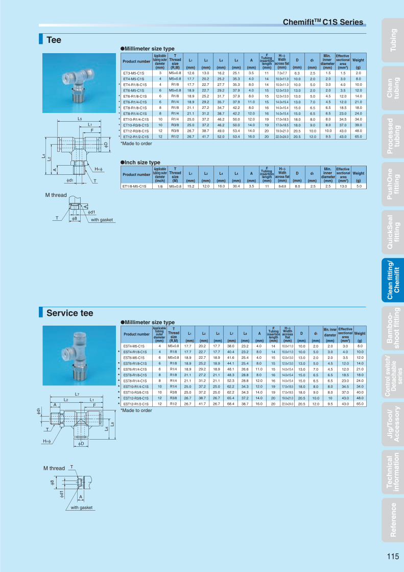
Tub
ing
Cle
an
tub
ing
Pu
sh
On
efi
ttin
gQ
uic
kS
ea
lfi
ttin
gB
amb
oo
-sh
oo
t fi
ttin
gC
ontr
ol s
witc
h/D
etac
habl
ese
ries
Cle
an f
itti
ng
/C
hem
ifit
Jig
/To
ol/
Accesso
ryR
efer
ence
Pro
cess
edtu
bin
gTe
chn
ical
info
rmat
ion
TeeMillimeter size type
Inch size type
3.5
4.0
8.0
4.0
8.0
11.0
8.0
12.0
12.0
14.0
14.0
16.0
11
14
14
15
15
15
16
16
19
19
20
20
7.0×7.7
10.0×11.0
10.0×11.0
12.0×13.0
12.0×13.0
14.0×15.4
14.0×15.4
14.0×15.4
17.0×18.5
17.0×18.5
19.0×21.0
22.0×24.0
1.5
2.0
3.0
2.0
4.5
4.5
6.5
6.5
8.0
8.0
10.0
9.5
2.0
8.0
10.0
12.0
14.0
21.0
18.0
24.0
34.0
39.0
48.0
65.0
13.0
20.2
22.7
22.7
25.2
29.2
27.2
31.2
37.2
37.2
38.7
41.7
25.1
35.3
35.3
37.9
37.9
37.9
42.2
42.2
50.0
50.0
53.4
53.4
2.5
2.0
5.0
2.0
5.0
7.0
6.5
6.5
8.0
9.0
10.0
12.0
6.3
10.0
10.0
13.0
13.0
13.0
15.0
15.0
18.0
18.0
20.5
20.5
16.2
25.2
27.7
29.2
31.7
35.7
34.7
38.7
46.2
46.2
49.0
52.0
ET3-M5-C1S
ET4-M5-C1S
ET4-R1/8-C1S
ET6-M5-C1S
ET6-R1/8-C1S
ET6-R1/4-C1S
ET8-R1/8-C1S
ET8-R1/4-C1S
ET10-R1/4-C1S
ET10-R3/8-C1S
ET12-R3/8-C1S
ET12-R1/2-C1S
3
4
4
6
6
6
8
8
10
10
12
12
M5×0.8
M5×0.8
R1/8
M5×0.8
R1/8
R1/4
R1/8
R1/4
R1/4
R3/8
R3/8
R1/2
12.6
17.7
17.7
18.9
18.9
18.9
21.1
21.1
25.0
25.0
26.7
26.7
1.5
3.0
4.0
3.5
12.0
12.0
18.5
23.0
34.5
37.0
43.0
43.0
ET1/8-M5-C1S 1/8 M5×0.8 15.2 3.5 11 8×8.8 2.5 5.012.0 30.4 2.58.016.0 13.0
Service tee
EST4-M5-C1S
EST4-R1/8-C1S
EST6-M5-C1S
EST6-R1/8-C1S
EST6-R1/4-C1S
EST8-R1/8-C1S
EST8-R1/4-C1S
EST10-R1/4-C1S
EST10-R3/8-C1S
EST12-R3/8-C1S
EST12-R1/2-C1S
4
4
6
6
6
8
8
10
10
12
12
M5×0.8
R1/8
M5×0.8
R1/8
R1/4
R1/8
R1/4
R1/4
R3/8
R3/8
R1/2
17.7
17.7
18.9
18.9
18.9
21.1
21.1
25.0
25.0
26.7
26.7
4.0
8.0
4.0
8.0
11.0
8.0
12.0
12.0
14.0
14.0
16.0
14
14
15
15
15
16
16
19
19
20
20
10.0×11.0
10.0×11.0
12.0×13.0
12.0×13.0
14.0×15.4
14.0×15.4
14.0×15.4
17.0×18.5
17.0×18.5
19.0×21.0
22.0×24.0
2.0
3.0
2.0
4.5
4.5
6.5
6.5
8.0
8.0
10
9.5
8.0
10.0
12.0
14.0
21.0
18.0
24.0
34.0
40.0
48.0
65.0
20.2
22.7
22.7
25.2
29.2
27.2
31.2
37.2
37.2
38.7
41.7
38.0
40.4
41.6
44.1
48.1
48.3
52.3
62.2
62.2
65.4
68.4
2.0
5.0
2.0
5.0
7.0
6.5
6.5
8.0
9.0
10.0
12.0
10.0
10.0
13.0
13.0
13.0
15.0
15.0
18.0
18.0
20.5
20.5
17.7
17.7
18.9
18.9
18.9
21.1
21.1
25.0
25.0
26.7
26.7
23.2
23.2
25.4
25.4
26.6
28.8
28.8
34.3
34.3
37.2
38.7
3.0
4.0
3.5
12.0
12.0
18.5
23.0
34.5
37.0
43.0
43.0
Millimeter size type
*
*
*
*
*
*
*
*
*
*
*
*
*
*
*
*
*
*
Applicabletubing outer
diameter(mm)
TThread
size(R,M)
FTubing
insertionlength(mm)
Min. inner
diameter(mm)
H×φWidth
across flat(mm)
Weight
(g)
Effective sectional
area(mm2)
Product number D
(mm)
d1
(mm)
L2
(mm)
L1
(mm)
L4
(mm)
L5
(mm)
A
(mm)
Applicabletubing outer
diameter(inch)
TThread
size(M)
FTubing
insertionlength(mm)
Min. inner
diameter(mm)
H×φWidth
across flat(mm)
Weight
(g)
Effective sectional
area(mm2)
Product number D
(mm)
d1
(mm)
L2
(mm)
L1
(mm)
L4
(mm)
L5
(mm)
A
(mm)
Applicabletubingouter
diameter(mm)
TThread
size(R,M)
FTubing
insertionlength(mm)
Min. innerdiameter(mm)
H×φWidthacross
flat(mm)
Weight
(g)
Effectivesectional
area(mm2)
Product number d1
(mm)
L1
(mm)
L2
(mm)
L6
(mm)
L7
(mm)
L8
(mm)
A
(mm)
D
(mm)
115
φ8
φd1
A
with gasket
TM thread
L5
L1
F
φD
L4L2
A
φd1 T
H×φ
φd1
A
M thread
φ8 with gasketT
φD
φd1
L6L8
T
H×φ
AL2
FL1
L7
*Made to order
*Made to order
ChemifitTM C1S Series

Tub
ing
Cle
an
tub
ing
Pu
sh
On
efi
ttin
gQ
uic
kS
ea
lfi
ttin
gB
amb
oo
-sh
oo
t fi
ttin
gC
ontr
ol s
witc
h/D
etac
habl
ese
ries
Cle
an f
itti
ng
/C
hem
ifit
Jig
/To
ol/
Accesso
ryR
efer
ence
Pro
cess
edtu
bin
gTe
chn
ical
info
rmat
ion
Panel touch connector
Y jointMillimeter size type
3
4
4
6
6
6
8
8
10
10
12
12
M5×0.8
M5×0.8
R1/8
M5×0.8
R1/8
R1/4
R1/8
R1/4
R1/4
R3/8
R3/8
R1/2
26.2
38.4
40.9
41.7
44.2
48.2
48.3
52.3
60.2
60.2
64.2
67.2
3.5
4.0
8.0
4.0
8.0
11.0
8.0
12.0
12.0
14.0
14.0
16.0
11
14
14
15
15
15
16
16
19
19
20
20
7.0×7.7
10.0×11.0
10.0×11.0
12.0×13.0
12.0×13.0
14.0×15.4
14.0×15.4
14.0×15.4
17.0×18.5
17.0×18.5
19.0×21.0
22.0×24.0
1.5
2.0
3.5
2.0
4.5
4.5
6.5
6.5
8.0
8.0
10.0
9.5
—
2.0
3.5
2.5
9.0
9.0
17.5
20.0
27.5
28.0
40.0
40.0
13.3
21.0
21.0
25.2
25.2
25.2
29.2
29.2
35.5
35.5
40.5
40.5
2.5
2.0
5.0
2.0
5.0
7.0
6.5
6.5
8.0
9.0
10.0
12.0
6.3
10.0
10.0
13.0
13.0
13.0
15.0
15.0
18.0
18.0
20.5
20.5
2.0
3.2
3.2
4.2
4.2
4.2
4.2
4.2
4.2
4.2
4.2
4.2
6.0
9.7
9.7
12.5
12.5
12.5
14.5
14.5
17.5
17.5
20.0
20.0
10.9
13.9
13.9
15.2
15.2
15.2
16.8
16.8
18.7
18.7
20.7
20.7
7.0
11.0
11.0
12.2
12.2
12.2
14.2
14.2
17.5
17.5
20.0
20.0
EY3-M5-C1S
EY4-M5-C1S
EY4-R1/8-C1S
EY6-M5-C1S
EY6-R1/8-C1S
EY6-R1/4-C1S
EY8-R1/8-C1S
EY8-R1/4-C1S
EY10-R1/4-C1S
EY10-R3/8-C1S
EY12-R3/8-C1S
EY12-R1/2-C1S
—
9.0
11.0
12.0
15.0
22.0
20.0
25.0
33.0
41.0
52.0
70.0
Inch size type
1/8 M5×0.8 26.4 3.5 11 8.0×8.8 2.5 —17.0 2.58.0 3.28.011.7 9.0EY1/8-M5-C1S —
Millimeter size type
Inch size type
EPC1/8-C1S 1/8 26.1 14.0 18.0 —11 2.511.0 5.5 —1.6
EPC3-C1S 3 24.8 12.0 15.0 2.511 2.09.0 4.5 —1.6
Applicabletubing outer
diameter(mm)
TThread
size(R,M)
FTubinginsertionlength(mm)
H×φWidthacross
flat(mm)
Weight
(g)
Effectivesectional
area(mm2)
Product number D
(mm)
W
(mm)
d2
(mm)
d1
(mm)
P3
(mm)
P4
(mm)
Min.inner
diameter(mm)
L
(mm)
L11
(mm)
A
(mm)
Applicabletubing outer
diameter(inch)
TThread
size(M)
FTubinginsertionlength(mm)
H×φWidthacross
flat(mm)
Weight
(g)
Effectivesectional
area(mm2)
Product number D
(mm)
W
(mm)
d2
(mm)
d1
(mm)
P3
(mm)
P4
(mm)
Min.inner
diameter(mm)
L
(mm)
L11
(mm)
A
(mm)
Applicabletubing outer
diameter(mm)
tMax. panelthickness
(mm)
T1Recommended
panel holediameter(mm)
FTubing
insertionlength(mm)
Washerouter
diameter(mm)
Washerthickness
(mm)
Min. innerdiameter
(mm)
Weight
(g)
Effectivesectional
area(mm2)
Product number L
(mm)
H4
(mm)
Applicabletubing outer
diameter(inch)
tMax. panelthickness
(mm)
T1Recommended
panel holediameter(mm)
FTubing
insertionlength(mm)
Washerouter
diameter(mm)
Washerthickness
(mm)
Min. innerdiameter
(mm)
Weight
(g)
Effectivesectional
area(mm2)
Product number L
(mm)
H4
(mm)
116
T1 F
t H4
L
H4
*
*
*
*
*
*
*
*
*
φD
W
L11
φd2
P4
F
H×φ
T
φd1
A
L
P3
φd1
A
M thread
φ8 with gasketT
*Made to order
ChemifitTM C1S Series

Tub
ing
Cle
an
tub
ing
Pu
sh
On
efi
ttin
gQ
uic
kS
ea
lfi
ttin
gB
amb
oo
-sh
oo
t fi
ttin
gC
ontr
ol s
witc
h/D
etac
habl
ese
ries
Cle
an f
itti
ng
/C
hem
ifit
Jig
/To
ol/
Accesso
ryR
efer
ence
Pro
cess
edtu
bin
gTe
chn
ical
info
rmat
ion
117

Tub
ing
Cle
an
tub
ing
Pu
sh
On
efi
ttin
gQ
uic
kS
ea
lfi
ttin
gB
amb
oo
-sh
oo
t fi
ttin
gC
ontr
ol s
witc
h/D
etac
habl
ese
ries
Cle
an f
itti
ng
/C
hem
ifit
Jig
/To
ol/
Accesso
ryR
efer
ence
Pro
cess
edtu
bin
gTe
chn
ical
info
rmat
ion
TES FUK
Polybutene tubing Polyurethane processed tubingAntistatic tubing*1 *1 *1
UE
ChemifitTM Series
Handling instructions
Sealing mechanism
Operating fluid, working temperature range
Pressure condition
Applicable tubing
Product number example
Cross-sectional structure diagram
Features
Polyurethane tubingPolyolefin resin tubing Fluorocarbon resin tubing
ChemitTM CSE Series
Maximum working pressure:5.0MPaNegative pressure performance:
−101.294kPa
Reference
Distinction of millimeter/inch sizes
Threaded fitting for clean air, pure water and chemical liquids
(*1) Combinatory use of U2, U1, U5, TES, FUK, PB, UE or polyurethane processed tubing and Chemifit CSE series mixes general and clean type performances. When using them together in a clean environment, be aware of how this could lower the cleanliness level.
Contact us for various chemical liquids.
See “Combination List of Tubing and Fitting” on page 8.
*1 *1
Operating fluid Working temperature range
Air (clean air) −65°C∼+260°C
Water (pure water) 0°C∼+100°C
SUS316 threaded fitting2-piece assembly, consisting of nut and body, which utilizes Nitta’s proprietary mechanism.
Highly improved workability for attaching and detaching a tubingFitting body and insertion part have an integrated construction. The assembly nut has a built-in sleeve. Both the fitting body and the assembly nut are reusable.
Uniform workability for connecting tubingTubing connection is completed when the assembly nut reaches the fitting body. No need for torque control or special tools.
No rotation of tubing when the tubing is attachedA sleeve inside the assembly nut can rotate. Hence the inserted does not rotate with it.
Made in oil-free proccessAssembled after cleaning each part in a clean room.
High sealing performanceNitta's original sealing mechanism achieves high durability against degradation of sealing performance due to cold-hot cycle.
No need for additional tightening of nutConstruction with less stress relaxation ensures high sealing performance for a long period of time and the nut does not need to be tightened at maintenance.
Highly smooth inner surface and R sphere surface processing on elbow crossingThe surface roughness is below Ra3.2. The corner of the elbow is sphere surface processed, which reduces liquid and detergent remnants.
Silver plated thread inside assembly nutPrevents the body and assembly nuts from seizing when the tubing is tightened.
CSE - C 6×4 - R1/4
Chemifit CSE seriesShape
Thread sizeApplicable tubing outer diameter
See page 34 for the common handling instructions for fittings.
When the working conditions of tubes and fittings differ, use them under the lower specified conditions.
When water is used as the operating fluid, do not allow it to freeze.
Do not bend the pipe sharply near the tubing insertion port of the fitting. Keep the tubing straight for twice as long as the tubing diameter from the insertion port.
Caution:
Caution:
Caution:
Instruction manual ························P.178Chemical resistance specification table ···P.198Effective sectional area ·················P.168Negative-pressure performance list· ··P.169
U2 U1 U5 PL PN
Clean, Antistatic tubing
ES
TA
*1
Assembly nut
Body (SUS316)
Nut (SUS316)
Sleeve (SUS316)
118
Assembly nut
Millimeter size Inch size
The inch size type has a boss at the sleeve end to distinguish from millimeter size type.
Clean-consciousproduct
Nitta's original sealing mechanism achieves high durability against degradation of sealing performance due to cold-hot cycle. The mechanism does not cause stress relaxation, ensuring sealing performance for a long period of time. Also, the nut does not need to be tightened at maintenance.
NutSleeve
Tubing
Stress
Body
Assembly nut
PB UC USCUMC UML
Flexible fluorocarbonresin bilayer tubing Flame-resistant tubing

Tub
ing
Cle
an
tub
ing
Pu
sh
On
efi
ttin
gQ
uic
kS
ea
lfi
ttin
gB
amb
oo
-sh
oo
t fi
ttin
gC
ontr
ol s
witc
h/D
etac
habl
ese
ries
Cle
an f
itti
ng
/C
hem
ifit
Jig
/To
ol/
Accesso
ryR
efer
ence
Pro
cess
edtu
bin
gTe
chn
ical
info
rmat
ion
ChemitTM CSE SeriesShape list
ConnectorCSE-C*
Internal connectorCSE-FC*
90 degree elbowCSE-L*
TeeCSE-T*
Service teeCSE-ST*
Union connectorCSE-UC*
90 degree union elbowCSE-UL*
Bushing (internal/external)3A0
Socket (internal/external)330
Union teeCSE-UT*
Panel touch connectorCSE-UCT*
Assembly nutCSAN
119
Oil-free processing, Clean wrapping and packagingUltrasonic cleaning with no oil or fat used for assembling in a
clean room.High-barrier sheet packaging available
Work in a clean room
What is high-barrier sheet packaging?
Shipping
Packaging in small bag(individual packaging)
Heat sealing
Packaging inlarge bag
Zipper sealingAssembling
Packaging in presentation box or outer case
The packaging bags that Nitta uses have the highest gas barrier performance among clear bags.
The bags do not contain halogen, etc., for safe burning.
Cleaning
Ultrasonic cleaning Dry
In order to maintain the cleanliness of our products, no space for oxygen, water, or corrosive gas is allowed inside the package and a packaging bag with a high gas barrier is needed for protecting the content from these gases. To meet this requirement, Nitta provides high-barrier bags with a high gas barrier performance also for nitrogen sealing or atmospheric sealing.

Tub
ing
Cle
an
tub
ing
Pu
sh
On
efi
ttin
gQ
uic
kS
ea
lfi
ttin
gB
amb
oo
-sh
oo
t fi
ttin
gC
ontr
ol s
witc
h/D
etac
habl
ese
ries
Cle
an f
itti
ng
/C
hem
ifit
Jig
/To
ol/
Accesso
ryR
efer
ence
Pro
cess
edtu
bin
gTe
chn
ical
info
rmat
ion
Connector
Internal connectorMillimeter size type
CSE-FC6×4-R1/8
CSE-FC8×6-R1/4
CSE-FC10×8-R1/4
RC1/8
RC1/4
RC1/4
24.5
30.0
31.5
8.7
13.0
13.0
12.0
14.0
17.0
3.5
5.5
7.5
20.0
33.0
39.0
9.0
21.5
29.0
7
7.5
8.5
14.0×15.4
17.0×18.5
17.0×18.5
6×4
8×6
10×8
Applicabletubing
outer×innerdiameters
(mm)
TThread size
(RC)
H×φWidth
across flat(mm)
H2Width
across flat(mm)
Min. innerdiameter
(mm)
FTubing insertion
length(mm)
Effectivesectional
area(mm)
Weight
(g)
Product number L
(mm)
A
(mm)
*
*
CSE-C4×2-R1/8
CSE-C4×2-R1/4
CSE-C6×4-R1/8
CSE-C6×4-R1/4
CSE-C6×4-R3/8
CSE-C8×5-R1/8
CSE-C8×5-R1/4
CSE-C8×5-R3/8
CSE-C8×6-R1/8
CSE-C8×6-R1/4
CSE-C8×6-R3/8
CSE-C8×6-R1/2
CSE-C10×6.5-R1/4
CSE-C10×8-R1/4
CSE-C10×8-R3/8
CSE-C10×8-R1/2
CSE-C12×8-R1/4
CSE-C12×9-R1/4
CSE-C12×9-R3/8
CSE-C12×9-R1/2
CSE-C12×10-R1/4
CSE-C12×10-R3/8
CSE-C12×10-R1/2
CSE-C19×16-R1/2
CSE-C19×16-R3/4
4×2
4×2
6×4
6×4
6×4
8×5
8×5
8×5
8×6
8×6
8×6
8×6
10×6.5
10×8
10×8
10×8
12×8
12×9
12×9
12×9
12×10
12×10
12×10
19×16
19×16
R1/8
R1/4
R1/8
R1/4
R3/8
R1/8
R1/4
R3/8
R1/8
R1/4
R3/8
R1/2
R1/4
R1/4
R3/8
R1/2
R1/4
R1/4
R3/8
R1/2
R1/4
R3/8
R1/2
R1/2
R3/4
23.0
26.0
25.5
28.5
29.5
27.0
30.0
31.0
27.0
30.0
31.0
34.0
31.5
31.5
32.5
35.5
33.5
33.5
34.5
37.5
33.5
34.5
37.5
42.3
44.3
8.0
11.0
8.0
11.0
12.0
8.0
11.0
12.0
8.0
11.0
12.0
15.0
11.0
11.0
12.0
15.0
11.0
11.0
12.0
15.0
11.0
12.0
15.0
15.0
17.0
10.0
14.0
12.0
14.0
17.0
14.0
14.0
17.0
14.0
14.0
17.0
22.0
17.0
17.0
17.0
22.0
17.0
17.0
17.0
22.0
17.0
17.0
22.0
27.0
29.0
10.0
10.0
12.0
12.0
12.0
14.0
14.0
14.0
14.0
14.0
14.0
14.0
17.0
17.0
17.0
17.0
19.0
19.0
19.0
19.0
19.0
19.0
19.0
27.0
27.0
1.5
1.5
3.5
3.5
3.5
4.5
4.5
4.5
5.5
5.5
5.5
5.5
6.0
7.5
7.5
7.5
7.5
8.0
8.5
8.5
8.0
9.5
9.5
12.0
15.0
11.0
19.0
16.0
23.0
33.0
22.0
26.0
36.0
21.0
25.0
35.0
54.0
36.0
34.0
40.0
58.0
42.0
40.0
46.0
65.0
39.0
44.0
63.0
100.0
119.0
1.7
1.7
9.0
9.0
9.0
15.0
15.5
15.5
23.0
23.5
23.5
23.5
27.5
42.5
43.5
43.5
42.5
48.5
53.0
54.0
49.5
67.0
68.5
−
−
5.5
5.5
7
7
7
7.5
7.5
7.5
7.5
7.5
7.5
7.5
8.5
8.5
8.5
8.5
10
10
10
10
10
10
10
12.3
12.3
Product number
Applicabletubing
outer×innerdiameters
(mm)
TThread
size(R)
FTubing
insertionlength(mm)
L
(mm)
A
(mm)
H1Width
across flat(mm)
H2Width
across flat(mm)
Min. innerdiameter
(mm)
Weight
(g)
Effective sectional
area(mm2)
CSE-C1/4-R1/8
CSE-C1/4-R1/4
CSE-C1/4-R3/8
CSE-C3/8-R1/4
CSE-C3/8-R3/8
CSE-C3/8-R1/2
CSE-C1/2-R1/4
CSE-C1/2-R3/8
CSE-C1/2-R1/2
6.35×4.57
6.35×4.57
6.35×4.57
9.53×6.99
9.53×6.99
9.53×6.99
12.70×9.56
12.70×9.56
12.70×9.56
R1/8
R1/4
R3/8
R1/4
R3/8
R1/2
R1/4
R3/8
R1/2
25.5
28.5
29.5
32.0
33.0
36.0
35.0
36.0
39.0
8.0
11.0
12.0
11.0
12.0
15.0
11.0
12.0
15.0
12.0
14.0
17.0
17.0
17.0
22.0
19.0
19.0
22.0
12.0
12.0
12.0
17.0
17.0
17.0
22.0
22.0
22.0
4.0
4.0
4.0
6.5
6.5
6.5
8.0
9.0
9.0
16.0
22.0
32.0
36.0
42.0
62.0
57.0
63.0
81.0
12.5
12.5
12.5
32.0
33.0
32.5
49.5
61.0
61.0
7
7
7
9
9
9
10.5
10.5
10.5
Millimeter size type
*
*
*
*
*
*
*
*Made to order
*
Inch size type
*Made to order
120
ChemifitTM CSE Series
H1 F
A
T
L
H2
H2 FAT
LH1×φ
Product number
Applicabletubing
outer×innerdiameters
(mm)
TThread
size(R)
FTubing
insertionlength(mm)
L
(mm)
A
(mm)
H1Width
across flat(mm)
H2Width
across flat(mm)
Min. innerdiameter
(mm)
Weight
(g)
Effective sectional
area(mm2)

Tub
ing
Cle
an
tub
ing
Pu
sh
On
efi
ttin
gQ
uic
kS
ea
lfi
ttin
gB
amb
oo
-sh
oo
t fi
ttin
gC
ontr
ol s
witc
h/D
etac
habl
ese
ries
Cle
an f
itti
ng
/C
hem
ifit
Jig
/To
ol/
Accesso
ryR
efer
ence
Pro
cess
edtu
bin
gTe
chn
ical
info
rmat
ion
*
*
*
*
*
*
*
*
*
*
*
*
*
*
*
*
90 degree elbow
Tee
CSE-L6×4-R1/8
CSE-L6×4-R1/4
CSE-L6×4-R3/8
CSE-L8×5-R1/4
CSE-L8×6-R1/8
CSE-L8×6-R1/4
CSE-L8×6-R3/8
CSE-L8×6-R1/2
CSE-L10×8-R1/4
CSE-L10×8-R3/8
CSE-L10×8-R1/2
CSE-L12×8-R1/4
CSE-L12×8-R1/2
CSE-L12×9-R1/4
CSE-L12×9-R3/8
CSE-L12×9-R1/2
CSE-L12×10-R1/4
CSE-L12×10-R3/8
CSE-L12×10-R1/2
CSE-L19×16-R3/8
CSE-L19×16-R1/2
CSE-L19×16-R3/4
6×4
6×4
6×4
8×5
8×6
8×6
8×6
8×6
10×8
10×8
10×8
12×8
12×8
12×9
12×9
12×9
12×10
12×10
12×10
19×16
19×16
19×16
R1/8
R1/4
R3/8
R1/4
R1/8
R1/4
R3/8
R1/2
R1/4
R3/8
R1/2
R1/4
R1/2
R1/4
R3/8
R1/2
R1/4
R3/8
R1/2
R3/8
R1/2
R3/4
23.5
23.5
26.0
25.0
25.0
25.0
27.5
29.0
29.0
29.0
30.5
31.0
32.5
31.0
31.0
32.5
31.0
31.0
32.5
37.3
37.3
38.8
17.0
20.0
24.0
20.0
18.0
20.0
24.0
27.0
23.0
24.0
27.0
23.0
27.0
23.0
24.0
27.0
23.0
24.0
27.0
27.5
30.5
34.0
30.5
30.5
35.5
32.0
32.0
32.0
37.0
40.0
38.5
38.5
41.5
40.5
43.5
40.5
40.5
43.5
40.5
40.5
43.5
50.3
50.3
53.3
24.0
27.0
33.5
28.1
26.1
28.1
33.5
38.0
32.8
33.8
38.0
34.0
38.0
34.0
35.0
38.0
34.0
35.0
38.0
43.1
46.1
49.6
8
11
12
11
8
11
12
15
11
12
15
11
15
11
12
15
11
12
15
12
15
17
14.0
14.0
19.0
14.0
14.0
14.0
19.0
22.0
19.0
19.0
22.0
19.0
22.0
19.0
19.0
22.0
19.0
19.0
22.0
26.0
26.0
29.0
12.0
12.0
12.0
14.0
14.0
14.0
14.0
14.0
17.0
17.0
17.0
19.0
19.0
19.0
19.0
19.0
19.0
19.0
19.0
27.0
27.0
27.0
6
8
10
8
6
8
10
12
8
10
12
8
12
8
10
12
8
10
12
10
12
15
3.5
3.5
3.5
4.5
5.5
5.5
5.5
5.5
7.5
7.5
7.5
7.5
7.5
8
8.5
8.5
8
9.5
9.5
10
12
15
33.0
35.0
72.0
42.0
37.0
38.0
74.0
98.0
77.0
79.0
116.0
85.0
110.0
83.0
85.0
107.0
80.0
83.0
106.0
192.0
201.0
267.0
8.5
8.5
8.0
−
19.0
20.0
20.5
20.5
35.0
37.0
−
34.0
38.0
40.5
44.0
48.5
47.5
54.0
56.0
−
−
−
7
7
7
7.5
7.5
7.5
7.5
7.5
8.5
8.5
8.5
10
10
10
10
10
10
10
10
12.3
12.3
12.3
CSE-L1/4-R1/8
CSE-L1/4-R1/4
CSE-L1/4-R3/8
CSE-L3/8-R1/4
CSE-L3/8-R3/8
CSE-L3/8-R1/2
CSE-L1/2-R1/4
CSE-L1/2-R3/8
CSE-L1/2-R1/2
6.35×4.57
6.35×4.57
6.35×4.57
9.53×6.99
9.53×6.99
9.53×6.99
12.70×9.56
12.70×9.56
12.70×9.56
R1/8
R1/4
R3/8
R1/4
R3/8
R1/2
R1/4
R3/8
R1/2
23.5
23.5
26.0
29.5
29.5
31.0
31.5
31.5
33.0
17.0
20.0
24.0
23.0
24.0
27.0
26.0
27.0
27.5
30.5
30.5
35.5
39.0
39.0
42.0
41.0
41.0
44.0
24.0
27.0
33.5
33.0
34.0
38.0
38.7
39.7
40.2
8
11
12
11
12
15
11
12
15
14.0
14.0
19.0
19.0
19.0
22.0
19.0
19.0
22.0
12.0
12.0
12.0
17.0
17.0
17.0
22.0
22.0
22.0
6.0
8.0
10.0
8.0
10.0
12.0
8.0
10.0
12.0
4.0
4.0
4.0
6.5
6.5
6.5
8.0
9.0
9.0
37.0
38.0
81.0
90.0
91.0
123.0
111.0
112.0
135.0
10.5
11.0
11.0
27.5
28.5
29.5
44.0
50.5
51.5
7
7
7
9
9
9
10.5
10.5
10.5
CSE-T1/4-R1/8
CSE-T1/4-R1/4
CSE-T1/4-R3/8
CSE-T3/8-R1/4
CSE-T3/8-R3/8
CSE-T3/8-R1/2
CSE-T1/2-R1/4
CSE-T1/2-R3/8
CSE-T1/2-R1/2
6.35×4.57
6.35×4.57
6.35×4.57
9.53×6.99
9.53×6.99
9.53×6.99
12.70×9.56
12.70×9.56
12.70×9.56
R1/8
R1/4
R3/8
R1/4
R3/8
R1/2
R1/4
R3/8
R1/2
23.5
23.5
26.0
29.5
29.5
31.0
31.5
31.5
33.0
17.0
20.0
24.0
23.0
24.0
27.0
26.0
27.0
27.5
24.0
27.0
33.5
33.0
34.0
38.0
38.7
39.7
40.2
47.0
47.0
52.0
59.0
59.0
62.0
63.0
63.0
66.0
8.0
11.0
12.0
11.0
12.0
15.0
11.0
12.0
15.0
14.0
14.0
19.0
19.0
19.0
22.0
19.0
19.0
22.0
12.0
12.0
12.0
17.0
17.0
17.0
22.0
22.0
22.0
6.0
8.0
10.0
8.0
10.0
12.0
8.0
10.0
12.0
4.0
4.0
4.0
6.5
6.5
6.5
8.0
9.0
9.0
47.0
49.0
93.0
112.0
114.0
142.0
149.0
151.0
175.0
−
−
−
−
−
−
−
−
−
7
7
7
9
9
9
10.5
10.5
10.5
CSE-T6×4-R1/8
CSE-T6×4-R1/4
CSE-T6×4-R3/8
CSE-T8×6-R1/8
CSE-T8×6-R1/4
CSE-T8×6-R3/8
CSE-T8×6-R1/2
CSE-T10×8-R1/4
CSE-T10×8-R3/8
CSE-T10×8-R1/2
CSE-T12×9-R1/4
CSE-T12×9-R3/8
CSE-T12×9-R1/2
CSE-T12×10-R1/4
CSE-T12×10-R3/8
CSE-T12×10-R1/2
6×4
6×4
6×4
8×6
8×6
8×6
8×6
10×8
10×8
10×8
12×9
12×9
12×9
12×10
12×10
12×10
R1/8
R1/4
R3/8
R1/8
R1/4
R3/8
R1/2
R1/4
R3/8
R1/2
R1/4
R3/8
R1/2
R1/4
R3/8
R1/2
23.5
23.5
26.0
25.0
25.0
27.5
29.0
29.0
29.0
30.5
31.0
31.0
32.5
31.0
31.0
32.5
17.0
20.0
24.0
18.0
20.0
24.0
27.0
23.0
24.0
27.0
23.0
24.0
27.0
23.0
24.0
27.0
24.0
27.0
33.5
26.1
28.1
33.5
38.0
32.8
33.8
38.0
34.0
35.0
38.0
34.0
35.0
38.0
47.0
47.0
52.0
50.0
50.0
55.0
58.0
58.0
58.0
61.0
62.0
62.0
65.0
62.0
62.0
65.0
8.0
11.0
12.0
8.0
11.0
12.0
15.0
11.0
12.0
15.0
11.0
12.0
15.0
11.0
12.0
15.0
14.0
14.0
19.0
14.0
14.0
19.0
22.0
19.0
19.0
22.0
19.0
19.0
22.0
19.0
19.0
22.0
12.0
12.0
12.0
14.0
14.0
14.0
14.0
17.0
17.0
17.0
19.0
19.0
19.0
19.0
19.0
19.0
6.0
8.0
10.0
6.0
8.0
10.0
12.0
8.0
10.0
12.0
8.0
10.0
12.0
8.0
10.0
12.0
3.5
3.5
3.5
5.5
5.5
5.5
5.5
7.5
7.5
7.5
8.0
8.5
8.5
8.0
9.5
9.5
48.0
50.0
94.0
54.0
56.0
102.0
127.0
109.0
110.0
138.0
119.0
121.0
149.0
115.0
117.0
145.0
−
−
−
−
−
20.5
−
34.0
−
−
−
−
−
−
−
−
7
7
7
7.5
7.5
7.5
7.5
8.5
8.5
8.5
10
10
10
10
10
10
Millimeter size type
Inch size type
*
*
*
*
*
*
*
*
*
*
*Made to order
*Made to order
Applicabletubing
outer×innerdiameters
(mm)
TThread
size(R)
FTubing
insertionlength(mm)
Min. inner
diameter(mm)
H2Width
across flat(mm)
H1Width
across flat(mm)
Weight
(g)
Effective sectional
area(mm2)
Product number d1
(mm)
L2
(mm)
L1
(mm)
L3
(mm)
L4
(mm)
A
(mm)
Applicabletubing
outer×innerdiameters
(mm)
TThread
size(R)
FTubing
insertionlength(mm)
Min. inner
diameter(mm)
H2Width
across flat(mm)
H1Width
across flat(mm)
Weight
(g)
Effective sectional
area(mm2)
Product number d1
(mm)
L2
(mm)
L1
(mm)
L3
(mm)
L4
(mm)
A
(mm)
Millimeter size type
Inch size type
*
*
*
*
*
*
*
*
*
*Made to order
*Made to order
Applicabletubing
outer×innerdiameters(mm)
TThread
size(R)
FTubing
insertionlength(mm)
Min. inner
diameter(mm)
H2Widthacross
flat(mm)
H1Widthacross
flat(mm)
Weight
(g)
Effective sectional
area(mm2)
Product number d1
(mm)
L2
(mm)
L1
(mm)
L4
(mm)
L5
(mm)
A
(mm)
Applicabletubing
outer×innerdiameters(mm)
TThread
size(R)
FTubing
insertionlength(mm)
Min. inner
diameter(mm)
H2Widthacross
flat(mm)
H1Widthacross
flat(mm)
Weight
(g)
Effective sectional
area(mm2)
Product number d1
(mm)
L2
(mm)
L1
(mm)
L4
(mm)
L5
(mm)
A
(mm)
121
ChemifitTM CSE Series
T
L4L2
A F
L1
L3
φd1
H1 H2
T
L4L2
A F
L1
L5
φd1
H1 H2

Tub
ing
Cle
an
tub
ing
Pu
sh
On
efi
ttin
gQ
uic
kS
ea
lfi
ttin
gB
amb
oo
-sh
oo
t fi
ttin
gC
ontr
ol s
witc
h/D
etac
habl
ese
ries
Cle
an f
itti
ng
/C
hem
ifit
Jig
/To
ol/
Accesso
ryR
efer
ence
Pro
cess
edtu
bin
gTe
chn
ical
info
rmat
ion
90 degree union elbow
Union connectorMillimeter size type
Millimeter size type
Inch size type
CSE-UC1/4
CSE-UC3/8
CSE-UC1/2
6.35×4.57
9.53×6.99
12.70×9.56
32.0
41.0
48.0
12.0
17.0
19.0
12.0
17.0
22.0
4
6.5
9
23.0
57.0
102.0
11.0
30.0
57.5
7
9.0
10.5
CSE-UL6×4
CSE-UL8×6
CSE-UL10×8
CSE-UL12×9
CSE-UL12×10
CSE-UL19×16
6×4
8×6
10×8
12×9
12×10
19×16
23.5
25.0
29.0
31.0
31.0
38.8
30.5
33.1
38.8
42.0
42.0
54.4
14.0
14.0
19.0
19.0
19.0
26.0
12.0
14.0
17.0
19.0
19.0
27.0
3.5
5.5
7.5
8.5
9.5
15.0
7.0
17.5
32.5
42.0
−
−
43.0
49.0
95.0
116.0
106.0
−
7
7.5
8.5
10
10
12.3
*
*
*Made to order
Service teeMillimeter size type
Applicable tubingouter×innerdiameters(mm)
FTubing insertion
length(mm)
H1Width
across flat(mm)
H2Width
across flat(mm)
Min. innerdiameter
(mm)
Weight
(g)
Effectivesectional
area(mm2)
Product number L1
(mm)
L3
(mm)
Applicable tubingouter×innerdiameters
(mm)
FTubing insertion
length(mm)
H2Width
across flat(mm)
H1Width
across flat(mm)
Min. innerdiameter
(mm)
Weight
(g)
Effectivesectional
area(mm2)
Product number L
(mm)
*
*
*
*
*
*
*Made to order
CSE-ST6×4-R1/8
CSE-ST6×4-R1/4
CSE-ST8×6-R1/4
CSE-ST10×8-R3/8
CSE-ST12×9-R1/2
CSE-ST12×10-R1/2
R1/8
R1/4
R1/4
R3/8
R1/2
R1/2
23.5
23.5
25.0
29.0
32.5
32.5
17.0
20.5
20.0
24.0
30.0
30.0
40.5
44.0
45.0
53.0
62.5
62.5
30.5
30.5
33.1
38.8
45.5
45.5
8
11
11
12
15
15
14.0
14.0
14.0
19.0
26.0
26.0
12.0
12.0
14.0
17.0
19.0
19.0
3.5
3.5
5.5
7.5
8.5
9.5
50.0
56.0
59.0
115.0
221.0
216.0
−
7.0
−
−
−
−
7
7
7.5
8.5
10
10
6×4
6×4
8×6
10×8
12×9
12×10
Product number
Applicabletubing
outer×innerdiameters
(mm)
TThread
size(R)
FTubing
insertionlength(mm)
L1
(mm)
A
(mm)
H1Widthacross
flat(mm)
H2Widthacross
flat(mm)
Min. innerdiameter(mm)
Weight
(g)
Effectivesectional
area(mm2)
L2
(mm)
L6
(mm)
L3
(mm)
Product number
Applicable tubingouter×innerdiameters
(mm)
FTubing insertion
length(mm)
L
(mm)
H1Width
across flat(mm)
H2Width
across flat(mm)
Min. innerdiameter
(mm)
Weight
(g)
Effectivesectional
area(mm2)
CSE-UC6×4
CSE-UC8×5
CSE-UC8×6
CSE-UC10×8
CSE-UC12×9
CSE-UC12×10
6×4
8×5
8×6
10×8
12×9
12×10
32.0
36.0
36.0
40.0
45.0
45.0
12.0
14.0
14.0
17.0
19.0
19.0
12.0
14.0
14.0
17.0
19.0
19.0
3.5
4.5
5.5
7.5
8.5
9.5
23.0
35.0
34.0
54.0
73.0
70.0
8.5
−
21.5
39.5
47.0
63.0
7
7.5
7.5
8.5
10
10
*
*Made to order
122
ChemifitTM CSE Series
H1
F
L1
T H2
L6
L3
F
L2
A
F
L
H1 H2
F
L3
L3
L1
L1
H2H1

Tub
ing
Cle
an
tub
ing
Pu
sh
On
efi
ttin
gQ
uic
kS
ea
lfi
ttin
gB
amb
oo
-sh
oo
t fi
ttin
gC
ontr
ol s
witc
h/D
etac
habl
ese
ries
Cle
an f
itti
ng
/C
hem
ifit
Jig
/To
ol/
Accesso
ryR
efer
ence
Pro
cess
edtu
bin
gTe
chn
ical
info
rmat
ion
Union tee
Panel touch connector
Assembly nutMillimeter size type
Inch size type
CSAN4
CSAN6
CSAN8
CSAN10
CSAN12
CSAN19
4
6
8
10
12
19
11.0
12.5
14.0
15.5
17.5
22.5
10.0
12.0
14.0
17.0
19.0
27.0
4.0
6.0
8.5
14.0
18.5
37.5
CSAN1/4
CSAN3/8
CSAN1/2
1/4
3/8
1/2
12.5
15.5
19.0
12.0
17.0
22.0
6.0
14.5
29.0
*Made to order*
Applicabletubing outer diameter
(inch)
H2Width across flat
(mm)
Weight(g)
Product number L(mm)
Applicabletubing outer diameter
(mm)
H2Width across flat
(mm)
Weight(g)
Product number L(mm)
CSE-UT6×4
CSE-UT8×5
CSE-UT8×6
CSE-UT10×8
CSE-UT12×9
CSE-UT12×10
6×4
8×5
8×6
10×8
12×9
12×10
23.5
25.0
25.0
29.0
31.0
31.0
47.0
50.0
50.0
58.0
62.0
62.0
30.5
33.1
33.1
38.8
42.0
42.0
14.0
14.0
14.0
19.0
19.0
19.0
12.0
14.0
14.0
17.0
19.0
19.0
3.5
4.5
5.5
7.5
8.5
9.5
59.0
72.0
68.0
127.0
140.0
133.0
7.0
11.5
16.5
31.5
−
−
7
7.5
7.5
8.5
10
10
Product number
CSE-UT1/4
CSE-UT3/8
CSE-UT1/2
6.35×4.57
9.53×6.99
12.70×9.56
23.5
29.5
33.0
47.0
59.0
66.0
30.5
39.5
45.7
14.0
19.0
22.0
12.0
17.0
22.0
4
6.5
9
55.0
129.0
204.0
−
−
45.5
7
9
10.5
CSE-UCT6×4
CSE-UCT8×5
CSE-UCT8×6
CSE-UCT10×8
CSE-UCT12×9
CSE-UCT12×10
6×4
8×5
8×6
10×8
12×9
12×10
45.0
48.0
48.0
51.0
54.5
54.5
12.0
14.0
14.0
17.0
19.0
19.0
21.0
22.0
22.0
26.0
27.0
27.0
M15×1
M17×1
M17×1
M20×1
M22×1
M22×1
6.0
6.0
6.0
6.0
5.5
5.5
3
3
3
3
3
3
28
30
30
34
37
37
3.5
4.5
5.5
7.5
8.5
9.5
7
7.5
7.5
8.5
10
10
70.0
85.0
83.0
121.0
139.0
135.0
8.0
−
21.0
40.5
47.5
63.0
21.0×23.0
22.0×24.5
22.0×24.5
26.0×29.0
27.0×30.0
27.0×30.0
Millimeter size type
Inch size type
*
*
*Made to order
*
*
*Made to order
Applicable tubingouter×innerdiameters(mm)
Min. innerdiameter
(mm)
FTubing insertion
length(mm)
H1Width
across flat(mm)
H2Width
across flat(mm)
Weight
(g)
Effectivesectional
area(mm2)
Product number L1
(mm)
L3
(mm)
L5
(mm)
Applicable tubingouter×innerdiameters(mm)
Min. innerdiameter
(mm)
FTubing insertion
length(mm)
H1Width
across flat(mm)
H2Width
across flat(mm)
Weight
(g)
Effectivesectional
area(mm2)
L1
(mm)
L3
(mm)
L5
(mm)
Millimeter size type
*Made to order
*
Applicabletubing
outer×innerdiameters
(mm)
tMax. panelthickness
(mm)
TThread
size(M)
FTubing
insertionlength(mm)
H2
Widthacross flat
(mm)
H3
Widthacross flat
(mm)
H1×φWidth
across flat(mm)
Washerouter
diameter(mm)
Washerthickness
(mm)
Min. innerdiameter
(mm)
Weight
(g)
Effectivesectional
area(mm2)
L
(mm)
Product number
123
ChemifitTM CSE Series
H2
H1
FL1L3
L5
L1
F
H2 H1×φ T H3
t
L
H2
L
H2

Tub
ing
Cle
an
tub
ing
Pu
sh
On
efi
ttin
gQ
uic
kS
ea
lfi
ttin
gB
amb
oo
-sh
oo
t fi
ttin
gC
ontr
ol s
witc
h/D
etac
habl
ese
ries
Cle
an f
itti
ng
/C
hem
ifit
Jig
/To
ol/
Accesso
ryR
efer
ence
Pro
cess
edtu
bin
gTe
chn
ical
info
rmat
ion
BushingMillimeter size type
SocketMillimeter size type
—
—
—
29.0
34.5
40.0
14.0
18.0
20.0
13.0
13.5
17.5
17.0×18.5
22.0×24.5
30.0×33.0
9.0
11.0
11.0
3A0-4-6-CS
3A0-6-8-CS
3A0-8-12-CS
R3/8
R1/2
R3/4
RC1/4
RC3/8
RC1/2
—
—
—
RC1/4
RC3/8
RC1/2
30.0
33.0
39.5
13.0
13.5
17.5
9.0
13.0
17.0
330-4-4-CS
330-6-6-CS
330-8-8-CS
17.0×18.5
19.0×21.0
24.0×26.5
H×φWidth across flat
(mm)
T2Thread size
(R)
T1Thread size
(RC)
d1
(mm)
A1
(mm)
A2
(mm)
Weight
(g)Product number
L
(mm)
H×φWidth across flat
(mm)
TThread size
(RC)
d1
(mm)
A
(mm)
Weight
(g)Product number
L
(mm)
124
ChemifitTM CSE Series
L
A1
A2
T2
T1
φd1
H×φ
L
AT
φd1
H×φ

Tub
ing
Cle
an
tub
ing
Pu
sh
On
efi
ttin
gQ
uic
kS
ea
lfi
ttin
gB
amb
oo
-sh
oo
t fi
ttin
gC
ontr
ol s
witc
h/D
etac
habl
ese
ries
Cle
an f
itti
ng
/C
hem
ifit
Jig
/To
ol/
Accesso
ryR
efer
ence
Pro
cess
edtu
bin
gTe
chn
ical
info
rmat
ion
125

Tub
ing
Cle
an
tub
ing
Pu
sh
On
efi
ttin
gQ
uic
kS
ea
lfi
ttin
gB
amb
oo
-sh
oo
t fi
ttin
gC
ontr
ol s
witc
h/D
etac
habl
ese
ries
Cle
an f
itti
ng
/C
hem
ifit
Jig
/To
ol/
Accesso
ryR
efer
ence
Pro
cess
edtu
bin
gTe
chn
ical
info
rmat
ion
ChemifitTM Series
Handling instructions
Operating fluid, working temperature range
Pressure condition
Applicable tubing
Product number example Distinction of millimeter/inch sizes
Cross-sectional structure diagram
Features
Polyolefin resin tubing Fluorocarbon resin tubing
ChemitTM CP Series
Threaded fitting made of polypropylene resinLightweight.
Made in oil-free processEach part is cleaned in a clean room.
Highly smooth inner surfaceSmooth inner surface due to ejection forming.
High performance, free of dust and contamination Made of special polypropylene resin.
Compliant with the MHLW Ministerial Notification No.201(2006), MHW Ministerial Notification No.370(1959), Japan
Maximum working pressure:0.4MPa(at20°C)Negative pressure performance:−99.975kPa
Reference
Threaded fitting for clean air, pure water and chemical liquids
Instruction manual ·······P.180Chemical resistance specification table ········P.198Effective sectional area ··P.168Negative-pressure performance list ··········P.169
Clean-consciousproduct
Millimeter size Inch size
The millimeter and inch size types of theChemifit CP series are distinguished bythe outer shape of the sleeve.
Sleeve
(*1) Use an insertion part (sold separately) to attach a flexible tubing.
CP - C 6 - R1/4
Chemifit CP series
Shape
Thread size
Applicable tubing outer diameter
See page 34 for the common handling instructions for fittings.
When the working conditions of tubes and fittings differ, use them under the lower specified conditions.
Use an insertion part (sold separately) to attach a flexible tubing.
Stress relaxation occurs more readily with resin thread than with metal thread. The relaxation is prominent at a high tempera-ture. Tighten the thread periodically.
For use at a high temperature within the working temperature range, tighten the nut periodically. If the nut cannot be tightened further, cut the tubing end and insert the tubing again with a new sleeve.
When water is used as the operating fluid, do not allow it to freeze.
Do not bend the pipe sharply near the tubing insertion port (sleeve end) of the fitting. Keep the tubing straight for twice as long as the tubing diameter from the insertion port.
Caution:
Caution:
Caution:
Caution:
Caution:
Caution:
TA TPPL PN
Body (special polypropylene resin)
Nut (special polypropylene resin)
Sleeve (special polypropylene resin)
*1
126
Operating fluid Working temperature range
Air (clean air) −20°C∼+80°C
Water (pure water) 0°C∼+80°C
Contact us for various chemical liquids.
See “Combination List of Tubing and Fitting” on page 8.

Tub
ing
Cle
an
tub
ing
Pu
sh
On
efi
ttin
gQ
uic
kS
ea
lfi
ttin
gB
amb
oo
-sh
oo
t fi
ttin
gC
ontr
ol s
witc
h/D
etac
habl
ese
ries
Cle
an f
itti
ng
/C
hem
ifit
Jig
/To
ol/
Accesso
ryR
efer
ence
Pro
cess
edtu
bin
gTe
chn
ical
info
rmat
ion
ChemitTM CP SeriesShape list
Using tubes at a pressure outside the range may cause accidents or damage, for which Nitta is not liable.
ConnectorCP-C*
90 degree elbowCP-L*
TeeCP-T*
Service teeCP-ST*
Union connectorCP-UC*
90 degree union elbowCP-UL*
Union teeCP-UT*
Insertion partCPI
NutCPN
SleeveCPS
Working temperature (°C)
Max
imum
wor
king
pre
ssur
e ch
ange
(M
Pa)
Relation between the working temperatureand the maximum working pressure
The maximum working pressure varies with the working temperature (environmental temperature). For use at an abnormal temperature, always check the maximum working pressure change in the graph below and keep the pressure within the indicated range.
127
Oil-free processing, Clean wrapping and packagingUltrasonic cleaning with no oil or fat used for assembling in a
clean room.High-barrier sheet packaging available
Work in a clean room
What is high-barrier sheet packaging?
Cleaning
Shipping
Ultrasonic cleaning
Packaging in small bag(5 pieces/bag)
Heat sealing
Packaging inlarge bag
Zipper sealingDry
Packaging in presentationbox or outer case
The packaging bags that Nitta uses have thehighest gas barrier performance among clear bags.
The bags do not contain halogen, etc., for safe burning.
In order to maintain the cleanliness of our products, no space for oxygen, water, or corrosive gas is allowed inside the package and a packaging bag with a high gas barrier is needed for protecting the content from these gases. To meet this requirement, Nitta provides high-barrier bags with a high gas barrier performance also for nitrogen sealing or atmospheric sealing.
_20 00
0.1
0.2
0.3
0.4
0.5
20 40 60 80
Caution:

Tub
ing
Cle
an
tub
ing
Pu
sh
On
efi
ttin
gQ
uic
kS
ea
lfi
ttin
gB
amb
oo
-sh
oo
t fi
ttin
gC
ontr
ol s
witc
h/D
etac
habl
ese
ries
Cle
an f
itti
ng
/C
hem
ifit
Jig
/To
ol/
Accesso
ryR
efer
ence
Pro
cess
edtu
bin
gTe
chn
ical
info
rmat
ion
ConnectorMillimeter size type
90 degree elbowMillimeter size type
Inch size type
CP-C4-R1/8
CP-C6-R1/8
CP-C6-R1/4
CP-C8-R1/8
CP-C8-R1/4
CP-C10-R1/4
CP-C10-R3/8
CP-C12-R3/8
CP-C12-R1/2
4
6
6
8
8
10
10
12
12
R1/8
R1/8
R1/4
R1/8
R1/4
R1/4
R3/8
R3/8
R1/2
29.8
37.1
37.1
42.5
45.0
46.8
48.6
57.7
59.9
17
19
19
22
22
29
29
29
29
12.0
14.0
14.0
16.5
16.5
18.5
18.5
24.0
24.0
12.0
14.0
14.0
16.5
16.5
19.0
19.0
21.5
21.5
2.8
5.0
5.0
6.0
6.0
8.0
8.0
9.9
9.9
3.5
11.0
11.0
24.5
24.5
37.0
37.0
54.0
54.0
8.0
12.0
12.0
9.0
12.0
12.0
13.5
13.5
15.5
4.3
5.0
5.0
6.0
6.0
8.0
8.0
9.9
9.9
2.0
3.0
3.0
5.0
5.0
6.0
7.0
11.0
13.0
CP-C1/4-R1/8
CP-C1/4-R1/4
CP-C3/8-R1/4
CP-C3/8-R3/8
CP-C1/2-R3/8
CP-C1/2-R1/2
1/4
1/4
3/8
3/8
1/2
1/2
R1/8
R1/4
R1/4
R3/8
R3/8
R1/2
37.4
37.4
45.9
47.7
58.2
60.7
19
19
28
28
29
29
14.0
14.0
18.5
18.5
24.0
24.0
5.0
5.0
8.0
8.0
9.9
9.9
15.0
15.0
34.0
34.0
59.0
59.0
12.0
12.0
12.0
13.5
13.5
15.5
5.0
5.0
8.0
8.0
9.9
9.9
14.0
14.0
19.0
19.0
22.0
22.0
3.0
3.0
6.0
7.0
11.0
13.0
Inch size type
CP-L4-R1/8
CP-L6-R1/8
CP-L6-R1/4
CP-L8-R1/8
CP-L8-R1/4
CP-L10-R1/4
CP-L10-R3/8
CP-L12-R3/8
CP-L12-R1/2
4
6
6
8
8
10
10
12
12
R1/8
R1/8
R1/4
R1/8
R1/4
R1/4
R3/8
R3/8
R1/2
26.8
29.1
29.1
37.0
37.0
41.8
41.8
45.7
45.7
32.6
36.0
36.0
43.9
43.9
51.3
51.3
56.3
56.3
10.0
12.0
12.0
12.0
12.0
16.5
16.5
18.5
18.5
12.0
14.0
14.0
16.5
16.5
19.0
19.0
21.5
21.5
2.8
5.0
5.0
6.0
6.0
8.0
8.0
9.9
9.9
21.0
23.0
23.0
24.0
27.0
27.0
27.0
27.0
27.0
4.0
5.0
5.0
6.0
6.0
8.0
8.0
9.9
9.9
27.9
31.1
31.1
33.5
36.5
37.9
37.9
39.4
39.4
8.0
12.0
12.0
9.0
12.5
12.0
13.5
13.7
16.0
17
19
19
22
22
29
29
29
29
3.0
4.0
4.0
6.0
6.0
9.0
10.0
12.0
14.0
3.0
10.0
10.0
19.5
19.5
30.0
30.0
46.0
46.0
CP-L1/4-R1/8
CP-L1/4-R1/4
CP-L3/8-R1/4
CP-L3/8-R3/8
CP-L1/2-R3/8
CP-L1/2-R1/2
1/4
1/4
3/8
3/8
1/2
1/2
29.4
29.4
40.9
40.9
46.2
46.2
36.3
36.3
50.4
50.4
56.8
56.8
12.0
12.0
16.5
16.5
18.5
18.5
14.0
14.0
19.0
19.0
22.0
22.0
5.0
5.0
8.0
8.0
9.9
9.9
23.0
23.0
27.0
27.0
27.0
27.0
5.0
5.0
8.0
8.0
9.9
9.9
31.1
31.1
37.9
37.9
39.7
39.7
12.0
12.0
12.0
13.5
13.5
16.0
19
19
28
28
29
29
R1/8
R1/4
R1/4
R3/8
R3/8
R1/2
12.0
12.0
29.0
29.0
53.0
53.0
4.0
4.0
9.0
10.0
12.0
14.0
Applicabletubing outer
diameter(mm)
TThread size
(R)
FTubing
insertionlength(mm)
H1Width
across flat(mm)
H2Width
across flat(mm)
Min. innerdiameter
(mm)
Weight
(g)
Effective sectional
area(mm2)
Product number d1
(mm)
L
(mm)
A
(mm)
Applicabletubing outer
diameter(inch)
TThread size
(R)
FTubing
insertionlength(mm)
H1Width
across flat(mm)
H2Width
across flat(mm)
Min. innerdiameter
(mm)
Weight
(g)
Effective sectional
area(mm2)
Product number d1
(mm)
L
(mm)
A
(mm)
Applicabletubing outer
diameter(mm)
TThread
size(R)
FTubing
insertionlength(mm)
Min. inner
diameter(mm)
H2Width
across flat(mm)
H1Width
across flat(mm)
Weight
(g)
Effective sectional
area(mm2)
Product number d1
(mm)
L2
(mm)
L1
(mm)
L3
(mm)
L4
(mm)
A
(mm)
Applicabletubing outer
diameter(inch)
TThread
size(R)
FTubing
insertionlength(mm)
Min. inner
diameter(mm)
H2Width
across flat(mm)
H1Width
across flat(mm)
Weight
(g)
Effective sectional
area(mm2)
Product number d1
(mm)
L2
(mm)
L1
(mm)
L3
(mm)
L4
(mm)
A
(mm)
128
ChemifitTM CP Series
H2
L3
L1
A
H1
L2L4
φd1
F
T
F
L
T
H2
φd1
A H1

Tub
ing
Cle
an
tub
ing
Pu
sh
On
efi
ttin
gQ
uic
kS
ea
lfi
ttin
gB
amb
oo
-sh
oo
t fi
ttin
gC
ontr
ol s
witc
h/D
etac
habl
ese
ries
Cle
an f
itti
ng
/C
hem
ifit
Jig
/To
ol/
Accesso
ryR
efer
ence
Pro
cess
edtu
bin
gTe
chn
ical
info
rmat
ion
Tee
Service tee
Millimeter size type
Millimeter size type
Inch size type
CP-T4-R1/8
CP-T6-R1/8
CP-T6-R1/4
CP-T8-R1/8
CP-T8-R1/4
CP-T10-R1/4
CP-T10-R3/8
CP-T12-R3/8
CP-T12-R1/2
4
6
6
8
8
10
10
12
12
R1/8
R1/8
R1/4
R1/8
R1/4
R1/4
R3/8
R3/8
R1/2
26.8
29.2
29.2
35.0
35.0
44.5
44.5
50.1
50.1
24.9
30.1
30.1
30.0
33.5
39.4
39.9
43.4
45.4
10.0
12.0
12.0
9.5
9.5
12.0
12.0
13.5
13.5
12.0
14.0
14.0
16.5
16.5
19.0
19.0
21.5
21.5
2.8
5.0
5.0
6.0
6.0
8.0
8.0
9.9
9.9
3.0
10.0
10.0
19.5
19.5
30.0
30.0
46.0
46.0
18.0
22.0
22.0
20.5
24.0
28.5
29.0
31.0
33.0
2.8
5.0
5.0
6.0
6.0
8.0
8.0
9.9
9.9
53.7
58.5
58.5
69.9
69.9
89.0
89.0
100.2
100.2
8.0
12.0
12.0
10.0
13.0
12.0
13.5
13.5
15.5
17
19
19
22
22
29
29
29
29
4.0
5.0
5.0
6.0
6.0
9.0
10.0
12.0
14.0
CP-T1/4-R1/8
CP-T1/4-R1/4
CP-T3/8-R1/4
CP-T3/8-R3/8
CP-T1/2-R3/8
CP-T1/2-R1/2
1/4
1/4
3/8
3/8
1/2
1/2
R1/8
R1/4
R1/4
R3/8
R3/8
R1/2
29.6
29.6
43.5
43.5
50.6
50.6
30.1
30.1
39.4
39.9
43.7
45.7
12.0
12.0
12.0
12.0
13.5
13.5
14.0
14.0
19.0
19.0
22.0
22.0
5.0
5.0
8.0
8.0
9.9
9.9
22.0
22.0
28.5
29.0
31.0
33.0
5.0
5.0
8.0
8.0
9.9
9.9
59.1
59.1
87.0
87.0
101.1
101.1
12.0
12.0
12.0
13.5
13.5
15.5
19
19
28
28
29
29
12.0
12.0
29.0
29.0
53.0
53.0
5.0
5.0
9.0
10.0
12.0
14.0
Inch size type
CP-ST4-R1/8
CP-ST6-R1/8
CP-ST6-R1/4
CP-ST8-R1/8
CP-ST8-R1/4
CP-ST10-R1/4
CP-ST10-R3/8
CP-ST12-R3/8
CP-ST12-R1/2
4
6
6
8
8
10
10
12
12
R1/8
R1/8
R1/4
R1/8
R1/4
R1/4
R3/8
R3/8
R1/2
26.8
29.1
29.1
35.5
35.5
44.8
44.8
50.2
50.2
26.8
29.1
29.1
35.5
35.5
44.8
44.8
50.2
50.2
10.0
12.0
12.0
9.5
9.5
12.0
12.0
13.5
13.5
12.0
14.0
14.0
16.5
16.5
19.0
19.0
21.5
21.5
2.8
5.0
5.0
6.0
6.0
8.0
8.0
9.9
9.9
18.0
22.0
22.0
21.0
23.5
28.0
30.0
30.3
32.5
2.8
5.0
5.0
6.0
6.0
8.0
8.0
9.9
9.9
44.8
51.1
51.1
56.5
59.0
72.8
74.8
80.5
82.7
8.0
12.0
12.0
10.0
13.0
12.0
13.5
13.5
15.5
17
19
19
22
22
29
29
29
29
33.7
37.1
37.1
45.0
45.0
53.8
53.8
62.5
62.5
3.0
10.0
10.0
19.5
19.5
30.0
30.0
46.0
46.0
4.0
5.0
5.0
6.0
6.0
9.0
9.0
12.0
14.0
CP-ST1/4-R1/8
CP-ST1/4-R1/4
CP-ST3/8-R1/4
CP-ST3/8-R3/8
CP-ST1/2-R3/8
CP-ST1/2-R1/2
1/4
1/4
3/8
3/8
1/2
1/2
R1/8
R1/4
R1/4
R3/8
R3/8
R1/2
29.4
29.4
43.9
43.9
50.7
50.7
29.4
29.4
43.9
43.9
50.7
50.7
12.0
12.0
12.0
12.0
13.5
13.5
14.0
14.0
19.0
19.0
22.0
22.0
5.0
5.0
8.0
8.0
9.9
9.9
22.0
22.0
28.0
30.0
30.3
32.5
5.0
5.0
8.0
8.0
9.9
9.9
51.4
51.4
71.9
73.9
81.0
83.2
12.0
12.0
12.0
13.5
13.5
16.0
19
19
28
28
29
29
37.5
37.5
54.8
54.8
63.3
63.3
12.0
12.0
29.0
29.0
53.0
53.0
5.0
5.0
9.0
9.0
12.0
14.0
Applicabletubing outer
diameter(mm)
TThread
size(R)
FTubing
insertionlength(mm)
Min. inner
diameter(mm)
H2Widthacross
flat(mm)
H1Widthacross
flat(mm)
Weight
(g)
Effective sectional
area(mm2)
Product number d1
(mm)
L2
(mm)
L1
(mm)
L4
(mm)
L5
(mm)
A
(mm)
Applicabletubing outer
diameter(inch)
TThread
size(R)
FTubing
insertionlength(mm)
Min. inner
diameter(mm)
H2Widthacross
flat(mm)
H1Widthacross
flat(mm)
Weight
(g)
Effective sectional
area(mm2)
Product number d1
(mm)
L2
(mm)
L1
(mm)
L4
(mm)
L5
(mm)
A
(mm)
Applicabletubing outer
diameter(mm)
TThread
size(R)
FTubing
insertionlength(mm)
Min. innerdiameter(mm)
H1Widthacross
flat(mm)
H2Widthacross
flat(mm)
Weight
(g)
Effectivesectional
area(mm2)
Product number d1
(mm)
L1
(mm)
L2
(mm)
L6
(mm)
L7
(mm)
L8
(mm)
A
(mm)
Applicabletubing outer
diameter(inch)
TThread
size(R)
FTubing
insertionlength(mm)
Min. innerdiameter(mm)
H1Widthacross
flat(mm)
H2Widthacross
flat(mm)
Weight
(g)
Effectivesectional
area(mm2)
Product number d1
(mm)
L1
(mm)
L2
(mm)
L6
(mm)
L7
(mm)
L8
(mm)
A
(mm)
129
ChemifitTM CP Series
L1H1
F
L5
L4
A
H2
φd1 T
L2
H1 H2
L6L8
F
T
A
L7
L2 L1
φd1

Tub
ing
Cle
an
tub
ing
Pu
sh
On
efi
ttin
gQ
uic
kS
ea
lfi
ttin
gB
amb
oo
-sh
oo
t fi
ttin
gC
ontr
ol s
witc
h/D
etac
habl
ese
ries
Cle
an f
itti
ng
/C
hem
ifit
Jig
/To
ol/
Accesso
ryR
efer
ence
Pro
cess
edtu
bin
gTe
chn
ical
info
rmat
ion
Union connector
Union tee
Millimeter size type
90 degree union elbowMillimeter size type
Millimeter size type
Inch size type
CP-UC4
CP-UC6
CP-UC8
CP-UC10
CP-UC12
4
6
8
10
12
38.7
43.2
57.4
63.2
77.4
12.0
14.0
16.5
18.5
24.0
12.0
14.0
16.5
19.0
21.5
2.8
5.0
6.0
8.0
10.0
3.0
3.0
5.0
9.0
15.0
17
19
22
29
29
3.0
10.0
22.0
35.5
51.0
CP-UC1/4
CP-UC3/8
CP-UC1/2
1/4
3/8
1/2
43.8
61.2
78.6
14.0
18.5
24.0
14.0
19.0
22.0
5.0
8.0
10.0
3.0
9.0
15.0
19
28
29
12.0
31.5
56.0
Inch size type
CP-UL6
CP-UL8
CP-UL10
CP-UL12
6
8
10
12
29.1
39.0(37.0)
41.8
45.7
12.0
12.0
16.5
18.5
14.0
16.5
19.0
21.5
5.0
6.0
8.0
10.0
19
22
29
29
37.1
48.5(46.5)
52.8
58.0
5.0
8.0
12.0
16.0
9.0
18.5
30.5
44.0
CP-UL1/4
CP-UL3/8
CP-UL1/2
1/4
3/8
1/2
29.4
40.9
46.2
12.0
16.5
18.5
14.0
19.0
22.0
5.0
8.0
10.0
19
28
29
37.5
51.8
58.8
5.0
12.0
16.0
11.5
27.0
49.0
Inch size type
CP-UT4
CP-UT6
CP-UT8
CP-UT10
CP-UT12
4
6
8
10
12
53.7
58.2
71.9
88.7
100.2
10.0
12.0
9.5
12.0
13.5
12.0
14.0
16.5
19.0
21.5
2.8
5.0
6.0
8.0
10.0
17
19
22
29
29
33.7
37.1
46.0
55.3
62.5
26.8
29.1
36.5(36.0)
44.3
50.1
5.0
8.0
11.0
15.0
20.0
2.5
9.0
18.5
30.5
44.0
CP-UT1/4
CP-UT3/8
CP-UT1/2
1/4
3/8
1/2
58.8
86.7
101.3
12.0
12.0
13.5
14.0
19.0
22.0
5.0
8.0
10.0
8.0
15.0
20.0
19
28
29
37.5
54.3
63.3
29.4
43.4
50.7
11.5
27.0
49.0
L1 and L8 of CP-UL8 have two lengths. Other length is inside parentheses.
L1 of CP-UT8 has two lengths. Other length is inside parentheses.
Applicable tubingouter diameter
(mm)
FTubing insertion
length(mm)
H1Width
across flat(mm)
H2Width
across flat(mm)
Min. innerdiameter
(mm)
Weight
(g)
Effectivesectional
area(mm2)
Product number L
(mm)
Applicable tubingouter diameter
(Inch)
FTubing insertion
length(mm)
H1Width
across flat(mm)
H2Width
across flat(mm)
Min. innerdiameter
(mm)
Weight
(g)
Effectivesectional
area(mm2)
Product number L
(mm)
Applicabletubing outer
diameter(mm)
FTubing insertion
length(mm)
H1Width
across flat(mm)
H2Width
across flat(mm)
Min. innerdiameter
(mm)
Weight
(g)
Effectivesectional
area(mm2)
Product number L1
(mm)
L8
(mm)
Applicabletubing outer
diameter(inch)
FTubing insertion
length(mm)
H1Width
across flat(mm)
H2Width
across flat(mm)
Min. innerdiameter
(mm)
Weight
(g)
Effectivesectional
area(mm2)
Product number L1
(mm)
L8
(mm)
Applicabletubing outer
diameter(inch)
FTubing insertion
length(mm)
H1Width
across flat(mm)
H2Width
across flat(mm)
Min. innerdiameter
(mm)
Weight
(g)
Effectivesectional
area(mm2)
Product number L1
(mm)
L5
(mm)
L8
(mm)
Applicabletubing outer
diameter(mm)
FTubing insertion
length(mm)
H1Width
across flat(mm)
H2Width
across flat(mm)
Min. innerdiameter
(mm)
Weight
(g)
Effectivesectional
area(mm2)
Product number L1
(mm)
L5
(mm)
L8
(mm)
130
ChemifitTM CP Series
H2 F
L
H1
H1
(L8)
L8
L1
(L1) F
H2
L1H1
F
L5
L8(L
1)
H2

Tub
ing
Cle
an
tub
ing
Pu
sh
On
efi
ttin
gQ
uic
kS
ea
lfi
ttin
gB
amb
oo
-sh
oo
t fi
ttin
gC
ontr
ol s
witc
h/D
etac
habl
ese
ries
Cle
an f
itti
ng
/C
hem
ifit
Jig
/To
ol/
Accesso
ryR
efer
ence
Pro
cess
edtu
bin
gTe
chn
ical
info
rmat
ion
Insertion partMillimeter size type
Inch size type
CPI 6×4
CPI 8×6
CPI 10×8
CPI 12×9
CPI12×10
6×4
8×6
10×8
12×9
12×10
Nut
SleeveMillimeter size type
CPI1/4
CPI3/8
CPI1/2
6.35×4.57
9.53×6.99
12.7×9.56
Millimeter sizetype
Inch sizetype
CPS4
CPS6
CPS8
CPS10
CPS12
4
6
8
10
12
Inch size type
CPS1/4
CPS3/8
CPS1/2
1/4
3/8
1/2
CPN4
CPN6
CPN8
CPN10
CPN12
CPN1/2
4
6
8
10
12
—
1.0
1.0
2.0
2.0
4.0
4.0
12.0
14.0
16.5
21.5
22.0
22.0
13.5
15.0
19.0
22.0
26.5
26.5
—
1/4
—
3/8
—
1/2
Caution: When using a flexible tubing such as a polyolefin resin tubing, insert it first to the insertion part before connecting to a fitting.
Caution: When you detach and re-attach a tubing, replace the nut with a new one.
Caution: When you detach and re-attach a tubing, replace the sleeve with a new one.
Applicable tubingouter diameter
(inch)
Product number
Applicable tubingouter diameter
(mm)0.1
0.1
0.2
0.4
0.4
0.1
0.3
0.5
Weight(g)
Weight(g)
Product number
Applicable tubingouter×innerdiameters
(mm)
Product number
Applicable tubingouter×innerdiameters
(mm)
Product number
H2Width
across flat(mm)
Weight
(g)
Applicable tubingouter diameterProduct number L
(mm)(mm) (Inch)
131
ChemifitTM CP Series
Tubing side
L
H2

Tub
ing
Cle
an
tub
ing
Pu
sh
On
efi
ttin
gQ
uic
kS
ea
lfi
ttin
gB
amb
oo
-sh
oo
t fi
ttin
gC
ontr
ol s
witc
h/D
etac
habl
ese
ries
Cle
an f
itti
ng
/C
hem
ifit
Jig
/To
ol/
Accesso
ryR
efer
ence
Pro
cess
edtu
bin
gTe
chn
ical
info
rmat
ion
Various shapes of barb fittings can be made by combining the connector and each part.
Sample combinations of barb fittings
Tubing size : 4×2.5
Thread size : M5
Tubing size : 6×4
Thread size : R1/8
+ +
+
+ +
+
+
+
++
+
Features
Various shapes can be made by combining the connector and each part.
Seal-processed PT thread requires no sealing tape.
Insert a tubing into the tubing connection part (bamboo-shoot shaped) until the tubing reaches the end. The thread part is attached in the same way as the PushOne series.
Operating fluid, working temperature range
Pressure condition
Product number example Applicable tubing
How to attach Maximum working pressure:0.4MPaNegative pressure performance:
−99.975kPa
Operating fluid Working temperature range
Air −40°C∼+80°C
Sample combination
Sample combination
Tubing size : 3.5×2
Thread size : M5
Sample combination
Tubing size : 4×2.5
Sample combination
Tubing size : 4×2.5
Sample combination
Tubing size : 6×4
Thread size : PT1/8
Sample combination
Tubing size : 3.5×2
Thread size : M5
Sample combination
Polyurethane tubing
See page 34 for the common handling instructionsfor fittings.
BN 4 - PT1/8
Shape
Applicable tubing outer diameter
Thread size
U5
(Body)Elbow block
BL-M5
Tee block
BT-M5
Connector Connector
BN6-M5 BN6-M5
Tee block
BT-M5
Adapter nipple
BAN-M5
Elbow block
BL-M5
Connector Connector
BN4-M5 BN4-M5
Tee block
BT-M5
Connector
BN4-M5
Connector
BN4-M5
Universal elbow block
BUVL-M5
Universal tee block
BUVT-M5
Connector
BN3.5-M5
Connector
BN3.5-M5
Connector
BN6-M5
Connector Connector
BN3.5-M5 BN3.5-M5
BAN-M5 BN4-M5
Adapter nipple Connector
(Body)
(Body)
(Body)
(Body)
(Body)
(Body, Thread side)
(Thread side) (Tubing side)
(Tubing side)
(Tubing side)
(Tubing side)
(Tubing side)
(Tubing side)
(Thread side)
132
Barb TypeBamboo-shoot Series
Adapter nipple Adapter bush
BAN-M5 BAB-M5-PT1/8
Connector
BN4-M5
(Tubing side)
(Thread side)
Elbow shape
Tee shape
Service tee shape
Union elbow shape
Union tee shape
Universal elbow shape
Universal tee shape
Adapter bush
BAB-M5-PT1/8
(Thread side)
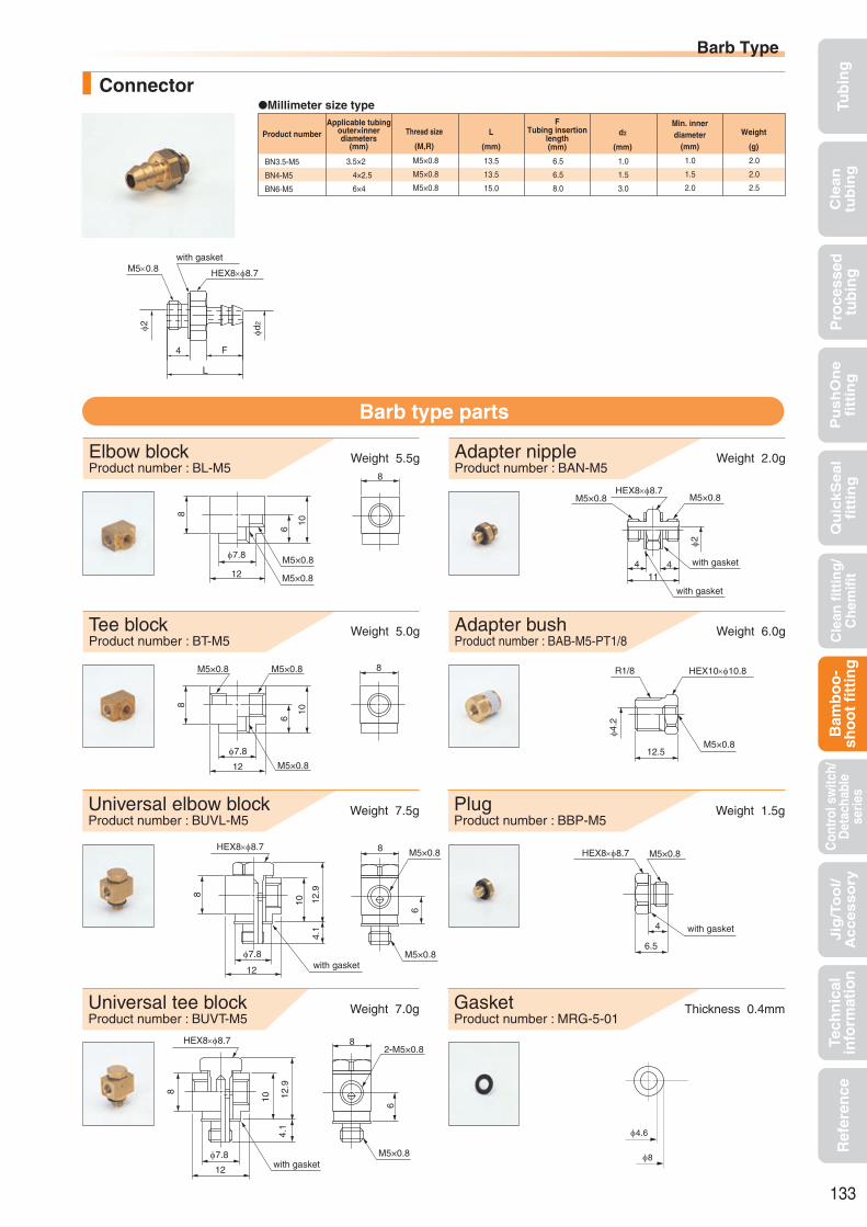
Tub
ing
Cle
an
tub
ing
Pu
sh
On
efi
ttin
gQ
uic
kS
ea
lfi
ttin
gB
amb
oo
-sh
oo
t fi
ttin
gC
ontr
ol s
witc
h/D
etac
habl
ese
ries
Cle
an f
itti
ng
/C
hem
ifit
Jig
/To
ol/
Accesso
ryR
efer
ence
Pro
cess
edtu
bin
gTe
chn
ical
info
rmat
ion
Millimeter size typeConnector
BN3.5-M5
BN4-M5
BN6-M5
3.5×2
4×2.5
6×4
13.5
13.5
15.0
1.0
1.5
3.0
1.0
1.5
2.0
2.0
2.0
2.5
M5×0.8
M5×0.8
M5×0.8
6.5
6.5
8.0
Elbow blockProduct number : BL-M5
Weight 5.5g Weight 2.0gAdapter nippleProduct number : BAN-M5
Tee blockProduct number : BT-M5
Weight 5.0g Weight 6.0gAdapter bushProduct number : BAB-M5-PT1/8
Barb type parts
Universal elbow blockProduct number : BUVL-M5
Weight 7.5g Weight 1.5gPlugProduct number : BBP-M5
Universal tee blockProduct number : BUVT-M5
Weight 7.0g Thickness 0.4mmGasketProduct number : MRG-5-01
φ4.6
φ8
Applicable tubingouter×innerdiameters
(mm)
Thread size
(M,R)
FTubing insertion
length(mm)
Min. innerdiameter
(mm)
Weight
(g)
Product number d2
(mm)
L
(mm)
φ7.8
12
8
6
10
M5×0.8
M5×0.8
8
8
φ7.8
8
M5×0.8
6
10
12
M5×0.8M5×0.8
8 M5×0.8
6
M5×0.8with gasket
8
10 12.9
4.1
HEX8×φ8.7
φ7.8
12
6
82-M5×0.8
M5×0.8with gasket
8
10 12.9
4.1
HEX8×φ8.7
φ7.8
12
φ2
M5×0.8M5×0.8HEX8×φ8.7
4 411
with gasket
with gasket
HEX10×φ10.8
φ4.2
M5×0.812.5
R1/8
4
6.5
HEX8×φ8.7 M5×0.8
with gasket
133
Barb Type
HEX8×φ8.7
F
L
φd2
M5×0.8
φ2
4
with gasket

Tub
ing
Cle
an
tub
ing
Pu
sh
On
efi
ttin
gQ
uic
kS
ea
lfi
ttin
gB
amb
oo
-sh
oo
t fi
ttin
gC
ontr
ol s
witc
h/D
etac
habl
ese
ries
Cle
an f
itti
ng
/C
hem
ifit
Jig
/To
ol/
Accesso
ryR
efer
ence
Pro
cess
edtu
bin
gTe
chn
ical
info
rmat
ion
Safety NoteThis Safety Note provides indications on the correct use of the product in order to prevent harm to people and property. The indications are classified into three categories, “danger”, “warning”, and “caution”, depending on the level of potential harm due to improper use. Each category contains important instructions on safety that should be followed in addition to the latest ISO 4414(*1), JIS B 8370(*2), ISO 4413 (*3), and JIS B 8361 (*4).(*1) ISO 4414 Pneumatic fluid power...Recommendations for the application of equipment to transmission and control systems.(*2) JIS B 8370(1988) Pneumatic System General Rules(*3) ISO 4413 Hydraulic fluid power...General rules for the application of equipment to transmission and control systems.(*4) JIS B 8361 Hydraulic System General Rules
DANGERWhere inappropriate use of this equipment may cause death or severe injury and where immediate warning of a dangerous situation ismandated.
WARNINGWhere inappropriate use of this equipment may cause death or severe injury.
CAUTIONWhere inappropriate use of this equipment may cause minor injury.
Before SelectionDANGER
•Cannot use for machines or equipment for life support.•To use for machines or equipment that require extremely high safety, measures have to be taken to prevent danger in the event tubing pulls out, bursts or leaks.
WARNING•Please contact us before using our products under conditions other than those specified in the catalog.•Please contact us before using our products for equipment, machines, various types of vehicles, and passenger aircraft, for leisure equipment passenger transport, for medical equipment that would cause human harm in case the specifications are not properly followed, and for machines in contact with food or drinking water.
SelectionWARNING
•Please check that our products are used under the “use conditions” specified in the catalog.•Do not use our products when a caustic or flammable gas is used as the fluid or is in the environment.
CAUTION•Cannot be used in locations subject to excessive vibration or impact.• If use conditions differ between the tubing and the fittings, use them under the lower specified conditions.•For Nitta’s fitting products, use tubing products that Nitta specifies or JIS B 8381-1995 on-spec products.•When a chemical is used in fluid or the environment, see “Chemical resistance specification table”. Contact us for chemical resistance of plating.•When spatter (hot wasted metal) is likely to stick to the fittings, use flame-resistant products only. Otherwise the spatter may cause a fire.•Couplers and nipples of the Q.D.C. 101 series and the 103 series cannot be connected to other manufactures products.•The maximum operating pressure varies for Chemifit C1 speed controller depending on the operating temperature. Please be sure to refer to “Relationship graph between operating temperature and maximum operating pressure” before selecting.
InstallationWARNING
•Fix tubes in place when installing them in a situation where unexpected disconnection of the tubing and connector could cause harm to people or property.
CAUTION•Attach the control, switch, and detachable series following the instruction manual of the fitting series that has the same tubing connector shape (ex. PushOne, QuickSeal, and Chemifit series).
•Do not throw or drop the control, switch, and detachable series. The impact may cause internal damage even if no outer damage is found.•Because the connection part of the fitting may swell or crack depending on the material, check the strength of the part when connecting.•Fittings with a sealing processed thread may swell due to the action of an operating fluid such as organic solvent, allowing fluid leakage from the thread part.•Do not bend the pipe sharply near the tubing insertion port (sleeve end) of the fitting. Keep the tubing straight for twice as long as the tubing diameter from the insertion port.•Do not use a fitting with a damaged thread or damaged tubing insertion port. In addition, please make sure that the product is not damaged when using a reusable product.•Nitta only guarantees products fabricated by designated companies.•Please do not install with tension applied on the tubing or a torsional or bending load applied on the fittings.•When using water as the operating fluid for the fitting series that has the same tubing connector shape (ex. PushOne, QuickSeal, and Chemifit series), avoid installing to a pleace where assembly could be moved.
•You cannot re-use sleeves that have QuickSeal series tubing connector shape. Replace them with a new sleeve each time you detach.•Please do not use the products in an environment where foreign materials may enter the product or come into contact with its internal parts. Doing so may result in damage or leakage.
•Please do not use the products in a manner where the screw side or the tube insertion opening side is rotated or oscillated repeatedly.
UsageWARNING
•Nitta’s products should be handled only by designers who have sufficient knowledge of equipment, instruments and systems in which our products are to be installed, or by persons responsible for determining specifications. Test and analysis should be conducted if necessary. The designers or the responsible persons are liable for the performance and the safety of the equipment, instruments and systems.
CAUTION•When water is used as fluid, do not allow it to freeze.•Do not touch a tubing at pressurization. Improperly treating or touching a tubing at pressurization may lead to danger from unexpected breakage or leakage of fluid.•Do not touch a tubing when the operating fluid is hot. Doing so may cause burns.•Use of the control, switch and detachable series in a place contaminated with many metal particles or dust could cause operation problems. Do not use them in such an environment.
StorageCAUTION
•When storing unused products, make sure to keep them in a clean place to prevent dust. When fine particles such as dust enter the inside of tubing products or the connected equipment, they may cause problems.
•Keep products in a dry place below 40°C avoiding direct sunlight. •Do not use tubing products that have been stored for more than one year after production.•The packaging of clean tubes should be opened just before use. Store the tubes in a box in a clean place in a dust-free environment.
Maintenance and InspectionCAUTION
•Before handling or removing Nitta’s products, be sure to check the safety by shutting off the power supply, stopping the pressure supply, evacuating pressurized air in the pipe, and terminating the operation of equipment, instruments, and systems.
•Please be sure to make periodic inspections. Confirm that there is no degradation such as outer damage, corrosion, and abrasion and replace any damaged piping.• If you are using a product with QuickSeal series tubing mounting shape continuously for a long period of time, or if you are using a product continuously under a high temperature range within the operating temperature range, please tighten the nut additionally on a regular basis.
DisposalCAUTION
•Dispose of unnecessary products as industrial waste or have them disposed of by a waste disposal firm. In particular, incineration of products containing fluorocarbon may generate a toxic pyrolysis gas.134
CONTROLControl Switch and Detachable SeriesHandling instructions for control switch and detachable series

Tub
ing
Cle
an
tub
ing
Pu
sh
On
efi
ttin
gQ
uic
kS
ea
lfi
ttin
gB
amb
oo
-sh
oo
t fi
ttin
gC
ontr
ol s
witc
h/D
etac
habl
ese
ries
Cle
an f
itti
ng
/C
hem
ifit
Jig
/To
ol/
Accesso
ryR
efer
ence
Pro
cess
edtu
bin
gTe
chn
ical
info
rmat
ion
135
CONTROLINDEXControl Series
Switch Series
ChemifitTM C1 speed controller
Ball valve
Switch Series
Valve built-in connector
Control Series
Throttle valve Miniature valve
Detachable Series
Q.D.C 101 Q.D.C 103
Suitable for environment (atmosphere) that requires chemical resistance
PushOne connection Inline type (ESU) allows
central control on the piping line.
Enables compact pipingPushOne connectionPosition of handle can be
changedNickel plated
Control Series
Control Series
Compact speed controller
Speed controller
Smaller than the conven-tional model
PushOne connectionElectroless nickel platedSealing-processed R thread
PushOne connection Inline type (ASU) allows
central control on the piping line
Electroless nickel plated
Fine control of flow rate Inline type (ASU) allows
central control on the piping linePushOne connectionElectroless nickel plated
Push-To-Connect typeAutomatic opening /closing
valve inside the couplerPushOne fitting integrated
types available
Push-To-Connect typeAutomatic opening /closing
valve inside the couplerSmaller than 101 seriesElectroless nickel plated
Valve inside fitting is opened/closed by attaching /detach-ing the tubing
PushOne connectionElectroless nickel plated
P.136 P.138
P.140 P.143
P.146 P.148
P.151
P.152 P.155
Easy flow rate controlPushOne connection for millimeter size type (quick seal type for inch size type)

Features
ChemitTM C1 Speed Controller
Suitable for environment (atmosphere) that requires chemical resistance
Mostly made of special polypropylene resin and SUS304. Special EPDM is used for sealing material.
PushOne connection of tubingJig and tool not required for connecting the tubes.
Inline type (ESU) allows central control on a pipe lineVarious kinds of piping are possible by fixing with connector pins and brackets.
PushOneTM Type
Control Series
Applicable tubing
Product number example Inline type connection
Cross-sectional structure diagram
Polyurethane tubingPolyolefin resin tubing Fluorocarbon resin tubing
(*1) Combinatory use of U2 or U1 tubing and Chemifit C1 speed controller mixes general and clean type performances.
When using them together in a clean environment, be aware of how this could lower the cleanliness level.
*1
*Non-scattering lubricant applied
ESC
ESU
Clean-consciousproduct
Inline type controllerscan be connectedwith a connector pin.
ESC 6 - R1/4 - O - C1SG
ShapeApplicable tubing outer diameter
Control method(O:Meter-out)
Chemifit C1 type
Thread size
See page 134 for the common handling instructions for control, switch and detachable series products.
Handling instructions
Control mechanism
Tub
ing
Cle
an
tub
ing
Pu
sh
On
efi
ttin
gQ
uic
kS
ea
lfi
ttin
gB
amb
oo
-sh
oo
t fi
ttin
gC
ontr
ol s
witc
h/D
etac
habl
ese
ries
Cle
an f
itti
ng
/C
hem
ifit
Jig
/To
ol/
Accesso
ryR
efer
ence
Pro
cess
edtu
bin
gTe
chn
ical
info
rmat
ion
ReferenceFlow characteristic graph ··············P.165
Operating fluid, working temperature range
Operating fluid Working temperature range
Air +5°C∼+60°C
Pressure condition
Meter-out
Controlling air flowfrom the thread side
Free flowControlled flow
Working temperature (°C)
0.8
0.7
0.6
0.5
0.4
0.3
0.2
0.1
0 10 15 20 25 30 35 40 45 50 55 605Max
imum
wor
king
pres
sure
cha
nge
(MPa
)
When the working conditions of tubes and fittings differ, use them under the lower specified conditions.
Tighten the lock nut and handle by hand, not by using a spanner.
The needle part stops when fully opened. Forced rotation could cause damage.
Cannot be used at a negative pressure.
Non-scattering lubricant is applied to some parts. Contact us for details.
Be sure to check the air flow direction when attaching a speed controller to equipment.
Do not bend the pipe sharply near the tubing insertion port (sleeve end) of the fitting. Keep the tubing straight for twice as long as the tubing diameter from the insertion port.
Cannot be used for sealing purposes.
Caution:
Caution:
Caution:
Caution:
Caution:
Caution:
Caution:
Caution:
Maximum working pressure:0.7MPa(at20°C)
136
TA TP U2 U1
Relation between the working temperatureand the maximum working pressure
Maximum working pressure varies with working temperature (environmental temperature). For use at an abnormal temperature, always check the maximum working pressure change in the graph below and keep pressure within the range.
PL PN
Handle (SUS304)
Lock nut (SUS304)
O ring (EPDM)*
Tubing seal (EPDM)*
Body (special polypropylene resin)
Release sleeve (special polypropylene resin)
Lock ring (SUS301)Collar (SUS304)
Back ring (special polypropylene resin)
Check seal (special NBR)*
Adapter (SUS304)
Snap ring (SUS304)
Tubing
Handle (SUS304)
Lock nut (SUS304)
O ring (EPDM)*
Needle (SUS304)
Tubing seal (EPDM)*
Body(special polypropylene resin)
Release sleeve(special polypropylene resin)
Lock ring (SUS304) Collar (SUS304)
Back ring(special polypropylene resin)
Check seal (special EPDM)*
Tubing

Tub
ing
Cle
an
tub
ing
Pu
sh
On
efi
ttin
gQ
uic
kS
ea
lfi
ttin
gB
amb
oo
-sh
oo
t fi
ttin
gC
ontr
ol s
witc
h/D
etac
habl
ese
ries
Cle
an f
itti
ng
/C
hem
ifit
Jig
/To
ol/
Accesso
ryR
efer
ence
Pro
cess
edtu
bin
gTe
chn
ical
info
rmat
ion
137
Inline type
Connector pin
Connector pin (polypropylene resin)
C
D
φd
A
B
Applicable fittingproduct number
Product number
HPN4-C1
HPN6-C1
ESU4-C1SG
ESU6-C1SG
ESU8-C1SG
Bracket
Bracket (SUS304)
Applicable fittingproduct number
Product number
SBRK4
SBRK6
SBRK8
A
(mm)
18.0
24.0
26.0
10.0
14.0
14.0
B
(mm)
18.5
26.0
30.0
C
(mm)
ESU4-C1SG
ESU6-C1SG
ESU8-C1SG
6.5
6.5
6.5
D
(mm)
5.0
5.0
5.0
d
(mm)
A
K
L2
L3
L1
T φD1
F
H×φ
φNφM
φD
W
L1
P2
NM
φd
F FL
D
KP
1L2
ESC4-R1/8-O-C1SG
ESC6-R1/8-O-C1SG
ESC6-R1/4-O-C1SG
ESC8-R1/8-O-C1SG
ESC8-R1/4-O-C1SG
ESC8-R3/8-O-C1SG
ESC10-R1/4-O-C1SG
ESC10-R3/8-O-C1SG
ESC12-R3/8-O-C1SG
4
6
6
8
8
8
10
10
12
R1/8
R1/8
R1/4
R1/8
R1/4
R3/8
R1/4
R3/8
R3/8
23.9
23.2
25.2
24.8
26.8
28.8
29.7
31.7
32.7
9.7
9.7
13.6
9.7
13.6
14.1
13.6
14.1
14.1
14
15
15
16
16
16
19
19
20
13.0×14.0
13.0×14.0
17.0×18.3
13.0×14.0
17.0×18.3
21.0×22.6
17.0×18.3
21.0×22.6
21.0×22.6
13.0
13.0
13.0
13.0
13.0
16.0
13.0
16.0
16.0
10.0
13.0
13.0
15.0
15.0
15.0
18.0
18.0
20.5
26.0
27.0
51.0
29.0
52.0
84.0
55.0
87.0
116.0
17.7
17.7
23.1
17.7
23.1
24.6
23.1
24.6
24.6
30.6
30.0
34.9
31.6
36.5
40.8
39.4
43.7
44.7
42.0
42.0
48.7
42.0
48.7
51.5
48.7
51.5
51.5
10.0
10.0
10.0
10.0
10.0
13.0
10.0
13.0
13.0
13.5
13.5
19.4
13.5
19.4
24.0
19.4
24.0
24.0
46.8
46.8
55.2
46.8
55.2
59.0
55.2
59.0
59.0
Millimeter size type
ESU4-C1SG
ESU6-C1SG
ESU8-C1SG
4
6
8
20.0
28.0
30.0
14
15
16
8.0
13.0
13.0
8.0
10.0
10.0
3.2
4.2
4.2
11.0
32.0
48.0
6.4
9.0
10.3
42.7
48.5
56.6
29.5
43.5
47.7
9.7
12.5
14.5
10.6
15.0
17.6
26.9
39.8
42.1
6.0
8.2
9.2
14.0
20.0
22.0
Controlled flow
Free flow
Control directions are marked by arrows on the top of the body.
Controlled flow Free flow
Free flow Controlled flow
JIS symbols are marked on both sides of the body.
Control direction markJIS symbol mark
JIS symbol
ChemifitTM C1 Speed Controller
Elbow typeMillimeter size type
Applicabletubing outer
diameter(mm)
TThread
size(R)
FTubing
insertionlength(mm)
H×φWidth
across flat(mm)
Weight
(g)
Product number D1
(mm)
D
(mm)
M
(mm)
N
(mm)
L2
(mm)
L1
(mm)
L3
(mm)Full open(mm)
Full closed(mm)
A
(mm)
K
Applicabletubing outer
diameter(mm)
FTubing insertionlength(mm)
Weight
(g)
Product number d
(mm)
W
(mm)
D
(mm)
M
(mm)
N
(mm)
L2
(mm)
L1
(mm)
L
(mm)
P1
(mm)
P2
(mm)Full open
(mm)Full closed
(mm)
K

Tub
ing
Cle
an
tub
ing
Pu
sh
On
efi
ttin
gQ
uic
kS
ea
lfi
ttin
gB
amb
oo
-sh
oo
t fi
ttin
gC
ontr
ol s
witc
h/D
etac
habl
ese
ries
Cle
an f
itti
ng
/C
hem
ifit
Jig
/To
ol/
Accesso
ryR
efer
ence
Pro
cess
edtu
bin
gTe
chn
ical
info
rmat
ion
Handling instructions
Control mechanism
Operating fluid, working temperature range
Applicable tubing
Product number example Distinction of Meter-out/in types
Cross-sectional structure diagram
Features
Compact Speed Controller
Smaller than the conventional modelEasy fine adjustment at low flow rate
Compact size with a maximum flow rate comparable to that of the conventional model. (See the graph.)
PushOne connection of tubingJig and tool not required for connecting the tubes.
Flame-resistant resin(compliant with V-0 of UL94 standard)Made of flame-resistant resin PBT. High self-extinguishing performance is compliant with V-0 of UL94 standard. Usable under an environment with spatters.
Electroless nickel platedPrevents degradation of surface and dissolution of copper ions into fluid.
Sealing-processed R threadSealing tape is not required.
Reference
PushOneTM Type
Operating fluid Working temperature range
Air +5°C∼+60°C
Polyurethan tubing Nylon tubing Flame-resistant tubing Polyolefin resin tubing*1
ASC 6 - R1/4 - O
ShapeApplicable tubing outer diameter
Control method(O:Meter-out, I :Meter-in)
Thread size
U2 U1 N2 N5 N1 FS FW FWU FUK PL PN
See page 134 for the common handling instructions for control, switch and detachable series products.
When the working conditions of tubes and fittings differ, use them under the lower specified conditions.
Tighten the lock nut and handle by hand, not by using a spanner.
The needle part stops when fully opened. Forced rotation could cause damage.
Cannot be used at a negative pressure.
Be sure to check the air flow direction when attaching a speed controller to equipment.
Do not bend the pipe sharply near the tubing insertion port (sleeve end) of the fitting. Keep the tubing straight for twice as long as the tubing diameter from the insertion port.
Cannot be used for sealing purposes.
Caution:
Caution:
Caution:
Caution:
Caution:
Caution:
Caution:
Flow characteristic graph ···············P.163UL-94 standard flame test ·············P.195
138
Control Series
Handle (brass)*
Back ring (zinc alloy* or POM resin)
Body (flame-resistant PBT resin)
Release sleeve (flame-resistant PBT resin)
Lock nut (brass)*Needle (brass)*
Sealing processed(for R thread only)(fluorocarbon resin coating)
*Electroless nickel plated
Lock ring (stainless)
Collar (zinc alloy or brass)*
Tubing seal (special NBR)
O ring (special NBR)
Check seal (special NBR)
Adapter (brass)*
Check valve (brass)*
Meter-out
BlackMeter-out
Controlling air flowfrom the thread side
Meter-out/in types are distinguished by thecolor of the lock nut.
Controlling air flowto the thread side
Meter-in
Meter-in
Silver
(*1) Combinatory use of PL or PN tubing and compact speed controller mixes general and clean type performances. When using them together in a clean environment, be aware of how this could lower the cleanliness level.
Meter-in type has a black zinc chromate processed lock nut.
Flo
w r
ate
/m
in.(
AN
R)
1050
200
100
Rotation of needle (times)
Compact speed controllerSpeed controller
For elbow type with φ6 tube and R1/8 thread
(At 0.5MPa)
[Comparison of control flow with the conventional model]
Free flow
Controlledflow
Free flow
Controlledflow
*——————————————
Pressure condition
Maximum working pressure:1.0MPa
Fluorocarbon resin tubing
TA TP

Tub
ing
Cle
an
tub
ing
Pu
sh
On
efi
ttin
gQ
uic
kS
ea
lfi
ttin
gB
amb
oo
-sh
oo
t fi
ttin
gC
ontr
ol s
witc
h/D
etac
habl
ese
ries
Cle
an f
itti
ng
/C
hem
ifit
Jig
/To
ol/
Accesso
ryR
efer
ence
Pro
cess
edtu
bin
gTe
chn
ical
info
rmat
ion
Elbow typeMillimeter size type
Universal type
ASC4-M5-O
ASC4-M5-I
ASC4-R1/8-O
ASC4-R1/8-I
ASC6-M5-O
ASC6-M5-I
ASC6-R1/8-O
ASC6-R1/8-I
ASC6-R1/4-O
ASC6-R1/4-I
ASC8-R1/8-O
ASC8-R1/8-I
ASC8-R1/4-O
ASC8-R1/4-I
ASC8-R3/8-O
ASC8-R3/8-I
ASC10-R1/8-O
ASC10-R1/8-I
ASC10-R1/4-O
ASC10-R1/4-I
ASC10-R3/8-O
ASC10-R3/8-I
ASC10-R1/2-O
ASC10-R1/2-I
ASC12-R3/8-O
ASC12-R3/8-I
ASC12-R1/2-O
ASC12-R1/2-I
4
4
4
4
6
6
6
6
6
6
8
8
8
8
8
8
10
10
10
10
10
10
10
10
12
12
12
12
M5×0.8
M5×0.8
R1/8
R1/8
M5×0.8
M5×0.8
R1/8
R1/8
R1/4
R1/4
R1/8
R1/8
R1/4
R1/4
R3/8
R3/8
R1/8
R1/8
R1/4
R1/4
R3/8
R3/8
R1/2
R1/2
R3/8
R3/8
R1/2
R1/2
18.0
18.0
20.1
20.1
20.3
20.3
21.8
21.8
23.6
23.6
26.6
26.6
24.9
24.9
26.9
26.9
30.4
30.4
31.5
31.5
30.3
30.3
32.4
32.4
37.7
37.7
33.7
33.7
3.4
3.4
7.3
7.3
3.4
3.4
7.3
7.3
10.8
10.8
7.3
7.3
10.8
10.8
11.1
11.1
7.3
7.3
10.8
10.8
11.1
11.1
14.4
14.4
11.1
11.1
14.4
14.4
13.5
13.5
13.5
13.5
15.0
15.0
15.0
15.0
15.0
15.0
16.0
16.0
16.0
16.0
16.0
16.0
19.0
19.0
19.0
19.0
19.0
19.0
19.0
19.0
20.0
20.0
20.0
20.0
8.0×9.0
8.0×9.0
12.0×13.5
12.0×13.5
8.0×9.0
8.0×9.0
12.0×13.5
12.0×13.5
14.0×15.8
14.0×15.8
12.0×13.5
12.0×13.5
14.0×15.8
14.0×15.8
19.0×21.0
19.0×21.0
12.0×13.5
12.0×13.5
14.0×15.8
14.0×15.8
19.0×21.0
19.0×21.0
24.0×26.0
24.0×26.0
19.0×21.0
19.0×21.0
24.0×26.0
24.0×26.0
8.0
8.0
11.0
11.0
8.0
8.0
11.0
11.0
13.0
13.0
11.0
11.0
13.0
13.0
16.0
16.0
11.0
11.0
13.0
13.0
16.0
16.0
20.0
20.0
16.0
16.0
20.0
20.0
9.8
9.8
9.8
9.8
12.6
12.6
12.6
12.6
12.6
12.6
14.6
14.6
14.6
14.6
14.6
14.6
17.5
17.5
17.5
17.5
17.5
17.5
17.5
17.5
20.0
20.0
20.0
20.0
8.0
8.0
19.0
19.0
9.0
9.0
20.0
20.0
33.0
33.0
21.0
21.0
34.0
34.0
62.0
62.0
23.0
23.0
37.0
37.0
65.0
65.0
109.0
109.0
67.0
67.0
111.0
111.0
10.1
10.1
13.7
13.7
10.6
10.6
13.7
13.7
18.2
18.2
14.7
14.7
18.2
18.2
19.9
19.9
16.2
16.2
19.6
19.6
19.9
19.9
24.5
24.5
21.2
21.2
24.5
24.5
22.8
22.8
27.2
27.2
25.1
25.1
28.9
28.9
32.9
32.9
33.7
33.7
34.1
34.1
38.2
38.2
37.5
37.5
40.7
40.7
41.6
41.6
46.0
46.0
49.0
49.0
47.4
47.4
25.8
25.8
31.0
31.0
25.8
25.8
31.0
31.0
35.3
35.3
31.0
31.0
35.3
35.3
41.3
41.3
31.0
31.0
35.3
35.3
41.3
41.3
49.5
49.5
41.3
41.3
49.5
49.5
5.0
5.0
8.0
8.0
5.0
5.0
8.0
8.0
10.0
10.0
8.0
8.0
10.0
10.0
13.0
13.0
8.0
8.0
10.0
10.0
13.0
13.0
16.0
16.0
13.0
13.0
16.0
16.0
9.6
9.6
14.2
14.2
9.6
9.6
14.2
14.2
18.5
18.5
14.2
14.2
18.5
18.5
22.6
22.6
14.2
14.2
18.5
18.5
22.6
22.6
27.4
27.4
22.6
22.6
27.4
27.4
28.6
28.6
36.0
36.0
28.6
28.6
36.0
36.0
40.3
40.3
36.0
36.0
40.3
40.3
46.3
46.3
36.0
36.0
40.3
40.3
46.3
46.3
54.5
54.5
46.3
46.3
54.5
54.5
Applicabletubing outer
diameter(mm)
TThread
size(M,R)
FTubing
insertionlength(mm)
H×φWidth
across flat(mm)
Weight
(g)
Product number D1
(mm)
D
(mm)
M
(mm)
N
(mm)
L2
(mm)
L1
(mm)
L3
(mm)Full open(mm)
Full closed(mm)
A
(mm)
K
139
A
K
L2
L3
L1
T φD1
F
H×φ
φNφM
φD
M5
φd1
A
φ8 with gasketT
Compact Speed Controller
Millimeter size typeApplicable
tubing outerdiameter
(mm)
Product number L1
(mm)
FTubing
insertionlength(mm)
Weight
(g)
D1
(mm)
H×φWidth
across flat(mm)
ASD4-M5-O
ASD4-M5-I
ASD4-R1/8-O
ASD4-R1/8-I
ASD6-M5-O
ASD6-M5-I
ASD6-R1/8-O
ASD6-R1/8-I
ASD6-R1/4-O
ASD6-R1/4-I
ASD8-R1/8-O
ASD8-R1/8-I
ASD8-R1/4-O
ASD8-R1/4-I
ASD8-R3/8-O
ASD8-R3/8-I
ASD10-R1/4-O
ASD10-R1/4-I
ASD10-R3/8-O
ASD10-R3/8-I
4
4
4
4
6
6
6
6
6
6
8
8
8
8
8
8
10
10
10
10
M5×0.8
M5×0.8
R1/8
R1/8
M5×0.8
M5×0.8
R1/8
R1/8
R1/4
R1/4
R1/8
R1/8
R1/4
R1/4
R3/8
R3/8
R1/4
R1/4
R3/8
R3/8
9.9
9.9
12.2
12.2
9.9
9.9
12.2
12.2
14.3
14.3
16.1
16.1
18.2
18.2
20.3
20.3
18.2
18.2
20.3
20.3
3.4
3.4
7.3
7.3
3.4
3.4
7.3
7.3
10.8
10.8
7.3
7.3
10.8
10.8
11.1
11.1
10.8
10.8
11.1
11.1
11.0
11.0
11.0
11.0
12.0
12.0
12.0
12.0
12.0
12.0
16.0
16.0
16.0
16.0
16.0
16.0
19.0
19.0
19.0
19.0
8.0×9.0
8.0×9.0
12.0×13.5
12.0×13.5
8.0×9.0
8.0×9.0
12.0×13.5
12.0×13.5
14.0×15.8
14.0×15.8
12.0×13.5
12.0×13.5
14.0×15.8
14.0×15.8
19.0×21.0
19.0×21.0
14.0×15.8
14.0×15.8
19.0×21.0
19.0×21.0
8.0
8.0
11.0
11.0
8.0
8.0
11.0
11.0
13.0
13.0
11.0
11.0
13.0
13.0
16.0
16.0
13.0
13.0
16.0
16.0
8.0
8.0
8.0
8.0
10.0
10.0
10.0
10.0
10.0
10.0
14.6
14.6
14.6
14.6
14.6
14.6
17.5
17.5
17.5
17.5
8.0
8.0
18.0
18.0
8.0
8.0
19.0
19.0
32.0
32.0
22.0
22.0
36.0
36.0
64.0
64.0
38.0
38.0
66.0
66.0
KL2
(mm)
L3
(mm)
10.1
10.1
13.7
13.7
10.1
10.1
13.7
13.7
17.1
17.1
14.4
14.4
18.0
18.0
18.7
18.7
18.0
18.0
18.7
18.7
18.5
18.5
23.1
23.1
19.5
19.5
24.1
24.1
28.4
28.4
30.5
30.5
34.8
34.8
38.9
38.9
36.2
36.2
40.3
40.3
L4
(mm)
24.5
24.5
28.0
28.0
25.9
25.9
29.4
29.4
32.9
32.9
35.1
35.1
38.7
38.7
39.4
39.4
42.6
42.6
43.3
43.3
Full closed(mm)
A
(mm)
N
(mm)
M
(mm)
5.0
5.0
8.0
8.0
5.0
5.0
8.0
8.0
10.0
10.0
8.0
8.0
10.0
10.0
13.0
13.0
10.0
10.0
13.0
13.0
D
(mm)
9.6
9.6
14.2
14.2
9.6
9.6
14.2
14.2
18.5
18.5
14.2
14.2
18.5
18.5
22.6
22.6
18.5
18.5
22.6
22.6
Full open(mm)
28.6
28.6
36.0
36.0
28.6
28.6
36.0
36.0
40.3
40.3
36.0
36.0
40.3
40.3
46.3
46.3
40.3
40.3
46.3
46.3
25.8
25.8
31.0
31.0
25.8
25.8
31.0
31.0
35.3
35.3
31.0
31.0
35.3
35.3
41.3
41.3
35.3
35.3
41.3
41.3
TThread
size(M,R)
A
K
L2
L3
L1
TφD1
F
H×φ
φNφM φD
L4

Tub
ing
Cle
an
tub
ing
Pu
sh
On
efi
ttin
gQ
uic
kS
ea
lfi
ttin
gB
amb
oo
-sh
oo
t fi
ttin
gC
ontr
ol s
witc
h/D
etac
habl
ese
ries
Cle
an f
itti
ng
/C
hem
ifit
Jig
/To
ol/
Accesso
ryR
efer
ence
Pro
cess
edtu
bin
gTe
chn
ical
info
rmat
ion
Features
Speed Controller
PushOne connection of tubingJig and tool not required for connecting the tubes.
Centrally controllable on a pipe lineVarious kinds of piping are possible by fixing with connector pins and brackets.
Electroless nickel platedPrevents degradation of surface and dissolution of copper ions into fluid.
Flame-resistant resin (compliant with V-0 of UL94 standard)Made of flame-resistant resin PBT. High self-extinguishing performance is compliant with V-0 of UL94 standard. Usable under an environment with spatters.
PushOneTM Type
Control Series
Handling instructions
Inline type connection
Operating fluid, working temperature range
Applicable tubing
Cross-sectional structure diagram
Reference
Operating fluid Working temperature range
Air +5°C∼+60°C
Pressure condition
Maximum working pressure:1.0MPa
Controllers can be connected with aconnector pin.
See page 134 for the common handling instructions for control, switch and detachable series products.
When the working conditions of tubes and fittings differ, use them under the lower specified conditions.
Tighten the lock nut and handle by hand, not by using a spanner.
The needle part stops when fully opened. Forced rotation could cause damage.
Cannot be used at a negative pressure.
Be sure to check the air flow direction when attaching a speed controller to equipment.
Do not bend the pipe sharply near the tubing insertion port (sleeve end) of the fitting. Keep the tubing straight for twice as long as the tubing diameter from the insertion port.
Cannot be used for sealing purposes.
Caution:
Caution:
Caution:
Caution:
Caution:
Caution:
Caution:
140
Flow characteristic graph ·············P.167UL-94 standard flame test············P.195
Polyurethan tubing Nylon tubing Flame-resistant tubing Polyolefin resin tubing Fluorocarbon resin tubing
(*1) Combinatory use of PL, PN, TA or TP tubing and Speed controller mixes general and clean type performances. When using them together in a clean environment, be aware of how this could lower the cleanliness level.
*1 *1
TA TPU2 U1 U5 PL PNN2 N5 N1 FS FW FWU FUK
*Electroless nickel plated
ASU
Handle (brass)*
Lock nut (brass)*
O ring (special NBR)
O ring (special NBR)
Tubing seal (special NBR)
Body(flame-resistant PBT resin)
Release sleeve(flame-resistant PBT resin)
Back ring (stainless)
Collar (zinc alloy)*
Back ring (zinc alloy)*
Check seal (special NBR)
Tubing
Needle
Adapter (brass)*
Check valve (brass)*

Tub
ing
Cle
an
tub
ing
Pu
sh
On
efi
ttin
gQ
uic
kS
ea
lfi
ttin
gB
amb
oo
-sh
oo
t fi
ttin
gC
ontr
ol s
witc
h/D
etac
habl
ese
ries
Cle
an f
itti
ng
/C
hem
ifit
Jig
/To
ol/
Accesso
ryR
efer
ence
Pro
cess
edtu
bin
gTe
chn
ical
info
rmat
ion
Millimeter size type
Inline type
W
L1
P2
φN φM
φd
F FL
φD
KP
1L2
ASU4
ASU6
ASU8
4
6
8
20.0
28.0
30.0
13.5
15.0
16.0
8.0
11.0
13.0
5.0
8.0
10.0
3.2
4.2
4.2
11.5
31.0
48.0
6.4
9.0
10.3
41.8
47.6
55.8
29.5
43.5
47.7
9.8
12.6
14.6
10.6
15.0
17.6
26.9
39.8
42.1
6.0
8.2
9.2
14.0
20.0
22.0
Connector pin
Connector pin
Applicable fittingproduct number
Product number
HPN4
HPN6
ASU4
ASU6
ASU8
Bracket
Bracket
Applicable fittingproduct number
Product number
BRK4
BRK6
BRK8
A
(mm)
18.0
24.0
26.0
10.0
14.0
14.0
B
(mm)
18.5
26.0
30.0
C
(mm)
ASU4
ASU6
ASU8
6.5
6.5
6.5
D
(mm)
5.0
5.0
5.0
d
(mm)
Controlled flow
Free flow
Control directions are marked by arrows on the top of the body.
Controlled flow Free flow
Free flow Controlled flow
JIS symbols are marked on both sides of the body.
Control direction markJIS symbol mark
JIS symbol
C
D
φd
A
B
Applicabletubing outer
diameter(mm)
FTubing insertion
length(mm)
Weight
(g)
Product number W
(mm)
D
(mm)
d
(mm)
M
(mm)
N
(mm)
L2
(mm)
P2
(mm)
L1
(mm)
P1
(mm)
L
(mm)Full open
(mm)Full closed
(mm)
K
141
Speed Controller

Tub
ing
Cle
an
tub
ing
Pu
sh
On
efi
ttin
gQ
uic
kS
ea
lfi
ttin
gB
amb
oo
-sh
oo
t fi
ttin
gC
ontr
ol s
witc
h/D
etac
habl
ese
ries
Cle
an f
itti
ng
/C
hem
ifit
Jig
/To
ol/
Accesso
ryR
efer
ence
Pro
cess
edtu
bin
gTe
chn
ical
info
rmat
ion
142

Tub
ing
Cle
an
tub
ing
Pu
sh
On
efi
ttin
gQ
uic
kS
ea
lfi
ttin
gB
amb
oo
-sh
oo
t fi
ttin
gC
ontr
ol s
witc
h/D
etac
habl
ese
ries
Cle
an f
itti
ng
/C
hem
ifit
Jig
/To
ol/
Accesso
ryR
efer
ence
Pro
cess
edtu
bin
gTe
chn
ical
info
rmat
ion
Caution:
143
Handling instructions
See page 134 for the common handling instructions for control, switch and detachable series products.
When the working conditions of tubes and fittings differ, use them under the lower specified conditions .
When water is used as the operating fluid, do not allow it to freeze.
Use the valve at fully open or closed position, not at an intermediate position.
Do not bend the pipe sharply near the tubing insertion port (sleeve end) of the fitting. Keep the tubing straight for twice as long as the tubing diameter from the insertion port.
Cannot be used at a negative pressure.
Detach the cap and the thread inside.
Detach the lever handle.
Attach the lever handle in new position at user’s discretion, then confirm that the handle can be opened or closed smoothly a full 90 degrees before tightening up the thread.
Attach the cap again.
Caution:
Caution:
Caution:
Caution:
1
2
3 90°
4
Position of the lever handle can be changed when the handle could be interfered with by any objects that would prevent it from opening or closing a full 90 degrees.
Features
Ball Valve
Enables compacting pipingIntegrated space-saving ball valve and PushOne fitting enables compact piping.
PushOne connection of tubingJig and tool not required for connecting the tubes.
Position of handle can be changedHandle can be re-attached in different position if it hits something when opened or closed.
Nickel platedPrevents degradation of surface and dissolution of copper ions into fluid.
PushOneTM Type
Switch Series
Change of open/close position of handle
Operating fluid, working temperature range
Applicable tubing
Product number example
Cross-sectional structure diagramOperating fluid Working temperature range
Air −20°C∼+80°C
Water −0°C∼+40°C
Pressure condition
Maximum working pressure:1.0MPa
(*1) Combinatory use of PL, PN, TA or TP tubing and ball valve mixes general and clean type performances. When using them together in a clean environment, be aware of how this could lower the cleanliness level.
Polyurethan tubing Nylon tubing Polyolefin resin tubing Fluorocarbon resin tubing*1 *1
Cap (PBT resin)
Lever handle (PBT resin)
Washer (brass)
Lock ring (stainless)
Tubing seal (special NBR)
Cap body (brass) nickel plated
Release sleeve (PBT resin)
Back ring (zinc alloy)Nickel plated
Collar (zinc alloy)Nickel plated
Thread (stainless)
Spindle (brass)
Ball (brass)Nickel chrome plated
Body (brass)Nickel chrome plated
O ring (NBR)
Ball sheet (PTFE resin)
V S - E 6 - F 1/4
Ball valve with PushOne E seriesShape
Applicable tubing outer diameter
Type
Thread shape (F= internal thread (RC), M=external thread (R))Thread size
TA TPU2 U1 U5 PL PNN2 N5 N1

Tub
ing
Cle
an
tub
ing
Pu
sh
On
efi
ttin
gQ
uic
kS
ea
lfi
ttin
gB
amb
oo
-sh
oo
t fi
ttin
gC
ontr
ol s
witc
h/D
etac
habl
ese
ries
Cle
an f
itti
ng
/C
hem
ifit
Jig
/To
ol/
Accesso
ryR
efer
ence
Pro
cess
edtu
bin
gTe
chn
ical
info
rmat
ion
Internal thread
Straight type
VS-E6-F1/8
VS-E6-F1/4
VS-E8-F1/8
VS-E8-F1/4
VS-E8-F3/8
VS-E10-F1/4
VS-E10-F3/8
VS-E12-F3/8
6
6
8
8
8
10
10
12
RC1/8
RC1/4
RC1/8
RC1/4
RC3/8
RC1/4
RC3/8
RC3/8
29.0
29.0
29.0
29.0
30.5
29.0
30.5
30.5
20.5
22.5
20.5
22.5
23.0
22.5
23.0
23.0
24.5
24.5
25.7
25.7
27.4
28.5
30.0
32.3
45.0
47.0
46.2
48.2
50.4
51.0
53.0
55.3
25.0
25.0
25.0
25.0
25.0
25.0
25.0
25.0
15
15
16
16
16
19
19
20
6.0
6.0
6.0
6.0
7.5
6.0
7.5
7.5
5.0
5.0
6.0
6.0
6.0
6.0
7.5
7.5
17
17
17
17
22
17
22
22
—
—
—
—
—
—
—
—
62.0
66.0
62.0
66.0
106.0
70.0
108.0
110.0
External thread
VS-E6-M1/8
VS-E6-M1/4
VS-E8-M1/8
VS-E8-M1/4
VS-E8-M3/8
VS-E8-M1/2
VS-E10-M1/4
VS-E10-M3/8
VS-E10-M1/2
VS-E12-M3/8
VS-E12-M1/2
6
6
8
8
8
8
10
10
10
12
12
R1/8
R1/4
R1/8
R1/4
R3/8
R1/2
R1/4
R3/8
R1/2
R3/8
R1/2
29.0
29.0
29.0
29.0
30.5
30.5
29.0
30.5
30.5
30.5
30.5
20.5
22.5
20.5
22.5
23.0
24.0
22.5
23.0
24.0
23.0
24.0
24.5
24.5
25.7
25.7
27.4
27.4
28.5
30.0
30.0
32.3
32.3
45.0
47.0
46.2
48.2
50.4
51.4
51.0
53.0
54.0
55.3
56.3
25.0
25.0
25.0
25.0
25.0
25.0
25.0
25.0
25.0
25.0
25.0
15
15
16
16
16
16
19
19
19
20
20
6.0
6.0
6.0
6.0
7.5
7.5
6.0
7.5
7.5
7.5
7.5
5.0
5.0
6.0
6.0
6.0
6.0
6.0
7.5
7.5
7.5
7.5
17
17
17
17
22
22
17
22
22
22
22
—
—
—
—
—
—
—
—
—
—
—
58.0
61.0
58.0
61.0
100.0
108.0
65.0
102.0
110.0
104.0
112.0
144
LHH
OPEN
(OPEN-SHUT an
gle of
hand
le)
L1D
2
D1
T
L4
L3L2
F
SHUT
90°
L1D
2
D1
T
L4
L3L2
F
LHH
OPEN
SHUT
90° (OPEN-SHUT angle of handle)
Ball Valve
Applicabletubing outer
diameter(mm)
TThread
size(RC)
FTubing
insertionlength(mm)
Weight
(g)
Effectivesectional
area(mm2)
Product number D1
(mm)
D2
(mm)
H
(mm)
L2
(mm)
L1
(mm)
L3
(mm)
L4
(mm)
LH
(mm)
Applicabletubing outer
diameter(mm)
TThread
size(R)
FTubing
insertionlength(mm)
Weight
(g)
Effectivesectional
area(mm2)
Product number D1
(mm)
D2
(mm)
H
(mm)
L2
(mm)
L1
(mm)
L3
(mm)
L4
(mm)
LH
(mm)

Tub
ing
Cle
an
tub
ing
Pu
sh
On
efi
ttin
gQ
uic
kS
ea
lfi
ttin
gB
amb
oo
-sh
oo
t fi
ttin
gC
ontr
ol s
witc
h/D
etac
habl
ese
ries
Cle
an f
itti
ng
/C
hem
ifit
Jig
/To
ol/
Accesso
ryR
efer
ence
Pro
cess
edtu
bin
gTe
chn
ical
info
rmat
ion
Internal thread
Angled type
VA-E6-F1/8
VA-E6-F1/4
VA-E8-F1/8
VA-E8-F1/4
VA-E8-F3/8
VA-E10-F1/4
VA-E10-F3/8
VA-E12-F3/8
6
6
8
8
8
10
10
12
RC1/8
RC1/4
RC1/8
RC1/4
RC3/8
RC1/4
RC3/8
RC3/8
24.5
24.5
25.7
25.7
27.4
28.5
30.0
32.3
19.0
21.0
19.0
21.0
24.0
21.0
24.0
24.0
29.0
29.0
29.0
29.0
31.0
29.0
31.0
31.0
48.0
50.0
48.0
50.0
55.0
50.0
55.0
55.0
25.0
25.0
25.0
25.0
25.0
25.0
25.0
25.0
15
15
16
16
16
19
19
20
6.0
6.0
6.0
6.0
7.5
6.0
7.5
7.5
5.0
5.0
6.0
6.0
6.0
6.0
7.5
7.5
17
17
17
17
22
17
22
22
—
—
—
—
—
—
—
—
68.0
65.0
68.0
65.0
114.0
69.0
103.0
118.0
External thread
VA-E6-M1/8
VA-E6-M1/4
VA-E8-M1/8
VA-E8-M1/4
VA-E8-M3/8
VA-E10-M1/4
VA-E10-M3/8
VA-E12-M3/8
VA-E12-M1/2
6
6
8
8
8
10
10
12
12
R1/8
R1/4
R1/8
R1/4
R3/8
R1/4
R3/8
R3/8
R1/2
24.5
24.5
25.7
25.7
27.4
28.5
30.0
32.3
32.3
20.0
21.0
20.0
21.0
25.0
21.0
25.0
25.0
27.0
29.0
29.0
29.0
29.0
31.0
29.0
31.0
31.0
31.0
49.0
50.0
49.0
50.0
56.0
50.0
56.0
56.0
57.0
25.0
25.0
25.0
25.0
25.0
25.0
25.0
25.0
25.0
15
15
16
16
16
19
19
20
20
6.0
6.0
6.0
6.0
7.5
6.0
7.5
7.5
9.0
5.0
5.0
6.0
6.0
6.0
6.0
7.5
7.5
7.5
17
17
17
17
22
17
22
22
22
—
—
—
—
—
—
—
—
—
61.0
64.0
61.0
64.0
110.0
68.0
112.0
106.0
113.0
145
D2 L4
L3L2
LHH
OPEN
(OPEN-SHUT an
gle of
hand
le)
SHUT
90°
TL1
F
D1
D2 L4
L3L2
LHH
OPEN
(OPEN-SHUT an
gle of
hand
le)
SHUT
90°
T
D1
L1
F
Ball Valve
Applicabletubing outer
diameter(mm)
TThread
size(RC)
FTubing
insertionlength(mm)
Weight
(g)
Effectivesectional
area(mm2)
Product number D1
(mm)
D2
(mm)
H
(mm)
L2
(mm)
L1
(mm)
L3
(mm)
L4
(mm)
LH
(mm)
Applicabletubing outer
diameter(mm)
TThread
size(R)
FTubing
insertionlength(mm)
Weight
(g)
Effectivesectional
area(mm2)
Product number D1
(mm)
D2
(mm)
H
(mm)
L2
(mm)
L1
(mm)
L3
(mm)
L4
(mm)
LH
(mm)

Tub
ing
Cle
an
tub
ing
Pu
sh
On
efi
ttin
gQ
uic
kS
ea
lfi
ttin
gB
amb
oo
-sh
oo
t fi
ttin
gC
ontr
ol s
witc
h/D
etac
habl
ese
ries
Cle
an f
itti
ng
/C
hem
ifit
Jig
/To
ol/
Accesso
ryR
efer
ence
Pro
cess
edtu
bin
gTe
chn
ical
info
rmat
ion
Caution:
ANC
146
Handling instructions
Operating fluid, working temperature range
Cross-sectional structure diagram
Features
Throttle Valve
Fine control of flow rateFlame-resistant resin (compliant with V-0 of UL94 standard)
Made of flame-resistant resin PBT. High self-extinguishing performance is compliant with V-0 of UL94 standard. Usable under an environment with spatters.
Inline type (ANU) allows central control on a pipe lineVarious kinds of piping are possible by fixing with connector pins and brackets.
PushOne connection of tubingJigs and tools are not required for connecting the tubes.
Electroless nickel platedPrevents degradation of the surface and dissolution of copper ions into fluid.
Sealing-processed R threadSealing tape is not required.
Reference
PushOneTM Type
Operating fluid Working temperature range
Air −20°C∼+80°C
Water 0°C∼+40°C
Control Series
Pressure condition
Maximum working pressure:1.0MPa
UL-94 standard flame test···························P.195
Inline type connection
Inline type controllers can be connected with a connector pin. (The photograph shows speed controllers.)
(*1) Combinatory use of PL, PN, TA or TP tubing and throttle valve mixes general and clean type performances. When using them together in a clean environment, be aware of how this could lower the cleanliness level.
Polyurethane tubing Nylon tubing Flame-resistant tubing Polyolefin resin tubing Fluorocarbon resin tubing*1 *1
ANU
TA TPU2 U1 U5 PL PNN2 N5 N1 FS FW FWU FUK
See page 134 for the common handling instructions for control, switch and detachable series products.
When the working conditions of tubes and fittings differ, use them under the lower specified conditions.
Tighten the lock nut and handle by hand, not by a spanner.
The needle part stops when fully opened. Forced rotation could cause damage.
When water is used as the operating fluid, do not allow it to freeze.
When water is used as the operating fluid, confirm that there is no water leakage damage to equipment and instruments due to construction failure.
Do not bend the pipe sharply near the tubing insertion port (sleeve end) of the fitting. Keep the tubing straight for twice as long as the tubing diameter from the insertion port.
Caution:
Caution:
Caution:
Caution:
Caution:
ANC 6 - R1/8
Shape
Applicable tubing outer diameter
Thread size
Product number example Distinction from speed controller
Handle (brass)*
Needle (brass)*
Handle (brass)*
Needle (brass)*
Lock nut (brass)*
Lock nut (brass : Trivalent Chromate)
Adapter (brass)*
Body (flame-resistant PBT resin)Tubing seal (special NBR)Back ring (zinc alloy)*
Lock ring (stainless)
Release sleeve(flame-resistant PBT resin)
O ring (special NBR)
Needle O ring (special NBR)
Check valve (brass)*
Collar (zinc alloy)*
*Electroless nickel plated
Body (flame-resistant PBT resin)Adapter (brass)*
Release sleeve(flame-resistant PBT resin)
Sealing processed(fluorocarbon resin coating)
Collar (zinc alloy)*
Tubing seal (special NBR)
Lock ring (stainless)
O ring (special NBR)
No arrow mark (left): Throttle valveArrow mark present (right): Speed controller
Check valve (brass)*
Back ring (zinc alloy)*
Applicable tubing

Tub
ing
Cle
an
tub
ing
Pu
sh
On
efi
ttin
gQ
uic
kS
ea
lfi
ttin
gB
amb
oo
-sh
oo
t fi
ttin
gC
ontr
ol s
witc
h/D
etac
habl
ese
ries
Cle
an f
itti
ng
/C
hem
ifit
Jig
/To
ol/
Accesso
ryR
efer
ence
Pro
cess
edtu
bin
gTe
chn
ical
info
rmat
ion
Millimeter size type
Elbow type
Inline type
ANC4-R1/8
ANC6-R1/8
4
6
20.1
21.8
13.5
15
12.0×13.5
12.0×13.5
11.0
11.0
19.0
20.0
13.7
13.7
27.2
28.9
36.0
36.0
8.0
8.0
9.8
12.6
31.0
31.0
R1/8
R1/8
7.3
7.3
14.2
14.2
Connector pin
Connector pin
Applicable fittingproduct numberProduct number
HPN4
HPN6
ANU4
ANU6
ANU8
Bracket
Bracket
Applicable fittingproduct number
Product number
BRK4
BRK6
BRK8
A
(mm)
18.0
24.0
26.0
10.0
14.0
14.0
B
(mm)
18.5
26.0
30.0
C
(mm)
ANU4
ANU6
ANU8
6.5
6.5
6.5
D
(mm)
5.0
5.0
5.0
d
(mm)
C
D
φd
A
B
Applicabletubing outer
diameter(mm)
Threadsize(R)
FTubing insertion
length(mm)
H×φWidth
across flat(mm)
D1
(mm)
Weight
(g)
Product number D
(mm)
M
(mm)
N
(mm)
L2
(mm)
L1
(mm)
L3
(mm)Full open
(mm)Full closed
(mm)
A
(mm)
K
Millimeter size type
Product
numberL1
(mm)
d
(mm)
ANU4
ANU6
ANU8
Applicabletubingouter
diameter(mm)
4
6
8
20.0
28.0
30.0
8.0
11.0
13.0
3.2
4.2
4.2
W
(mm)
10.6
15.0
17.6
Weight
(g)
11.5
31.0
48.0
KL2
(mm)
6.4
9.0
10.3
P1
(mm)
6.0
8.2
9.2
P2
(mm)
14.0
20.0
22.0
Full open(mm)
29.5
43.5
47.7
N
(mm)
M
(mm)
5.0
8.0
10.0
D
(mm)
9.8
12.6
14.6
Full closed(mm)
26.9
39.8
42.1
L
(mm)
41.8
47.6
55.8
FTubing
insertionlength(mm)
13
15
16
Effectivesectional
area(mm2)
—
—
—
147
Throttle Valve
A
K
L2
L1
L3
T
F
H×φ
φN
φD
φM
φD1
L1
P2
W
L2P
1
K
φN
φM
F FL
φd
φD

Tub
ing
Cle
an
tub
ing
Pu
sh
On
efi
ttin
gQ
uic
kS
ea
lfi
ttin
gB
amb
oo
-sh
oo
t fi
ttin
gC
ontr
ol s
witc
h/D
etac
habl
ese
ries
Cle
an f
itti
ng
/C
hem
ifit
Jig
/To
ol/
Accesso
ryR
efer
ence
Pro
cess
edtu
bin
gTe
chn
ical
info
rmat
ion
148
Handling instructions
Applicable tubing
Operating fluid, working temperature range
Product number example
PushOne type (millimeter size)
QuickSeal type (Inch size)
Features
Miniature Valve
Reference
Easy flow rate controlEasy operation with large handle.
Fine control of flow rateFine thread is used for valve system.
PushOne connection for millimeter size typeJigs and tools are not required for connecting the tubes.
Negative-pressure performance list··········P.169
PushOneTM Type and QuickSeal Type
Operating fluid Working temperature range
Air −20°C∼+80°C
Water 0°C∼+40°C
Control Series
Pressure conditionMaximum working pressure:1.0MPaNegative pressure performance:
−98.642kPa
Polyurethane tubing Nylon tubing Polybutene tubing
PB
Polyolefin resin tubing Fluorocarbon resin tubing
(*1) Combinatory use of PL, PN, TA or TP tubing and miniature valve mixes general and clean type performances. When using them together in a clean environment, be aware of how this could lower the cleanliness level.
*1 *1
(*1) Combinatory use of PL, PN, TA or TP tubing and miniature valve mixes general and clean type performances. When using them together in a clean environment, be aware of how this could lower the cleanliness level.
Polyurethane tubing Nylon tubing Polyolefin resin tubing Fluorocarbon resin tubing*1 *1
E MVB 6 - PT1/8
Type (E : PushOne type)
Shape
Thread size
Tubing size
TA TP
TA TP
U2 U1 U5
U2
PL PN
PL PN
N2 N5 N1
N2 N5 N1
Q MVB 1N 1/4 - R1/8
Type (Q: QuickSeal type)
Shape
Inch size type (group 1)
Thread size
Tubing size
See page 134 for the common handling instructions for control, switch and detachable series products.
When the working conditions of tubes and fittings differ, use them under the lower specified conditions.
When water is used as the operating fluid, do not allow it to freeze.
Do not bend the pipe sharply near the tubing insertion port (sleeve end) of the fitting. Keep the tubing straight for twice as long as the tubing diameter from the insertion port.
The miniature valve has a determined flow direction, which is indicated on the side body. Flow fluid in the correct direction to control the flow rate.
Caution:
Caution:
Caution:
Caution:

Tub
ing
Cle
an
tub
ing
Pu
sh
On
efi
ttin
gQ
uic
kS
ea
lfi
ttin
gB
amb
oo
-sh
oo
t fi
ttin
gC
ontr
ol s
witc
h/D
etac
habl
ese
ries
Cle
an f
itti
ng
/C
hem
ifit
Jig
/To
ol/
Accesso
ryR
efer
ence
Pro
cess
edtu
bin
gTe
chn
ical
info
rmat
ion
Millimeter size type
Inline type
Millimeter size type
Straight type
50.6
51.6
EMVA6
EMVA8
6
8
15.0
15.0
15
16
25.3
25.8
40.0
40.0
39.9
39.9
35.9
35.9
—
86.0
—
2.5
15.0
15.0
EMVB6-PT1/8
EMVB6-PT1/4
EMVB8-PT1/4
6
6
8
46.8
49.8
50.3
15.0
15.0
15.0
15
15
16
25.3
25.3
25.8
10.0
13.0
13.0
5.0
7.0
7.0
15.0
15.0
15.0
R1/8
R1/4
R1/4
21.5
24.5
24.5
39.9
39.9
39.9
40.0
40.0
40.0
35.9
35.9
35.9
3.5
3.5
—
81.0
84.5
—
Millimeter size type
Angled type
EMVC6-PT1/8
EMVC6-PT1/4
EMVC8-PT1/4
6
6
8
15.0
15.0
15.0
15
15
16
25.3
25.3
24.8
12.0
12.0
12.0
5.0
7.0
7.0
R1/8
R1/4
R1/4
23.0
23.0
23.0
57.9
57.9
57.9
40.0
40.0
40.0
53.9
53.9
53.9
7.0
—
7.0
76.5
—
78.0
15.0
15.0
15.0
149
F
LL1 H1
K
φM
φD
F
L
AT
L2 L1
H1
K
φd1
φM
φD
L1
φd1
φM
H1 F
K
A
L2
T
φD
Miniature Valve (PushOneTM type)
Applicabletubing outer
diameter(mm)
FTubing
insertionlength(mm)
H1Width
across flat(mm)
Effectivesectional
area(mm2)
Weight
(g)
Product number D
(mm)
L1
(mm)
L
(mm)Full open
(mm)Full closed
(mm)
M
(mm)
K
Applicabletubing outer
diameter(mm)
TThread
size(R)
FTubing
insertionlength(mm)
Weight
(g)
Effectivesectional
area(mm2)
Product number d1
(mm)
D
(mm)
L2
(mm)
L1
(mm)
A
(mm)
M
(mm)
H1Width
across flat(mm)
Full open(mm)
Full closed(mm)
K
Applicabletubing outer
diameter(mm)
TThread
size(R)
FTubing
insertionlength(mm)
Weight
(g)
Effectivesectional
area(mm2)
Product number d1
(mm)
D
(mm)
L2
(mm)
L
(mm)
L1
(mm)
A
(mm)
M
(mm)
H1Width
across flat(mm)
Full open(mm)
Full closed(mm)
K

Tub
ing
Cle
an
tub
ing
Pu
sh
On
efi
ttin
gQ
uic
kS
ea
lfi
ttin
gB
amb
oo
-sh
oo
t fi
ttin
gC
ontr
ol s
witc
h/D
etac
habl
ese
ries
Cle
an f
itti
ng
/C
hem
ifit
Jig
/To
ol/
Accesso
ryR
efer
ence
Pro
cess
edtu
bin
gTe
chn
ical
info
rmat
ion
150
Inline type
Straight type
Angled type
Inch size type
54.2
62.6
QMVA1N1/4
QMVA1N3/8
1/4
3/8
14.0
17.0
15
17
27.1
31.3
φ40.0
φ40.0
4.6
4.6
37.4
38.9
33.4
34.9
80.0
117.0
12.0
17.0
3.4
5.7
5.0
6.0
Inch size type
Inch size type
QMVB1N1/4-R1/8
QMVB1N1/4-R1/4
QMVB1N3/8-R1/4
1/4
1/4
3/8
46.6
48.6
56.3
14.0
14.0
17.0
15
15
17
76.0
95.0
113.0
27.1
27.1
31.3
10.0
12.0
12.0
4.6
4.6
4.6
12.0
12.0
17.0
3.4
3.4
5.7
R1/8
R1/4
R1/4
19.5
21.5
25.0
37.4
37.4
38.9
φ40.0
φ40.0
φ40.0
5.0
7.0
7.0
33.4
33.4
34.9
5.0
5.5
6.0
QMVC1N1/4-R1/8
QMVC1N1/4-R1/4
QMVC1N3/8-R1/4
1/4
1/4
3/8
14.0
14.0
17.0
15
15
17
75.0
92.0
104.0
27.1
27.1
28.3
10.0
12.0
12.0
4.6
4.6
4.6
12.0
12.0
17.0
3.4
3.4
5.7
R1/8
R1/4
R1/4
20.0
22.0
23.0
50.9
50.9
55.9
φ40.0
φ40.0
φ40.0
5.0
7.0
7.0
54.9
56.9
59.9
—
7.0
7.0
Miniature Valve (QuickSeal type)
K
φM
F
L1H1H2
L
S
φd2
K
φd2
φM
FTS
H2
L2 L1
L
H1A
φd1
L1
H2
φd1
φM
H1 FS
K
AL2
φd2
T
Applicabletubing outer
diameter(inch)
TThread
size(R)
FTubing
insertionlength(mm)
Weight
(g)
Effectivesectional
area(mm2)
Product number H2
(mm)
d1
(mm)
d2
(mm)
L2
(mm)
L1
(mm)
A
(mm)
S
(mm)
M
(mm)
H1Width
across flat(mm)
Full open(mm)
Full closed(mm)
K
Applicabletubing outer
diameter(inch)
TThread
size(R)
FTubing
insertionlength(mm)
Weight
(g)
Effectivesectional
area(mm2)
Product number H2
(mm)
d1
(mm)
d2
(mm)
L2
(mm)
L
(mm)
L1
(mm)
A
(mm)
M
(mm)
S
(mm)
H1Width
across flat(mm)
Full open(mm)
Full closed(mm)
K
Applicabletubing outer
diameter(inch)
FTubing
insertionlength(mm)
H1Width
across flat(mm)
Effectivesectional
area(mm2)
Weight
(g)
Product number H2
(mm)
d2
(mm)
L1
(mm)
L
(mm)Full open
(mm)Full closed
(mm)
S
(mm)
M
(mm)
K

Tub
ing
Cle
an
tub
ing
Pu
sh
On
efi
ttin
gQ
uic
kS
ea
lfi
ttin
gB
amb
oo
-sh
oo
t fi
ttin
gC
ontr
ol s
witc
h/D
etac
habl
ese
ries
Cle
an f
itti
ng
/C
hem
ifit
Jig
/To
ol/
Accesso
ryR
efer
ence
Pro
cess
edtu
bin
gTe
chn
ical
info
rmat
ion
151
Handling instructions
Operating fluid, working temperature range
Applicable tubing
Cross-sectional structure diagram
Features
Valve Built-in Connector
Valve inside fitting is opened/closed by attaching/detaching tubing The valve is automatically closed by detaching the tubing.
PushOne connection of tubingJigs and tools are not required for connecting the tubes.
Electroless nickel platedPrevents degradation of surface and dissolution of copper ions into fluid.
Sealing-processed R threadSealing tape is not required.
PushOneTM Type
Operating fluid Working temperature rangee
Air +20°C∼+60°C
Detachable Series
Pressure condition
Maximum working pressure:1.0MPa
Connector
ECV4-M5
ECV6-PT1/8
ECV6-PT1/4
4
6
6
32.6
40.4
31.4
16
17
17
10.0×11.0
14.0×15.4
14.0×15.4
10.0
13.0
13.0
11.0
26.0
21.0
2.0
4.0
4.0
M5×0.8
R1/8
R1/4
4.0
8.0
11.0
2.0
6.5
6.5
Millimeter size type
φD
FT
A
L
H×φ
φd1
φd1
φ8
4
M5×0.8
with gasket
Release sleeve(flame-resistant PBT resin)
Collar (zinc alloy)*
Lock ring (stainless)
Tubing
Back ring (zinc alloy)*
Tubing seal (special NBR)
Spacer (brass)*Body (brass)*
Valve stop (POM resin)
Valve (POM resin)
Spring (stainless)
Air
Open valve state
Closed valve state with no tubing
(*1) Combinatory use of PL, PN, TA or TP tubing and valve built-in connector mixes general and clean type performances. When using them together in a clean environment, be aware of how this could lower the cleanliness level.
Polyurethane tubing Nylon tubing Flame-resistant tubing Polyolefin resin tubing Fluorocarbon resin tubing*1 *1
*Electroless nickel plated
Applicabletubing outer
diameter(mm)
TThread size
(M,R)
FTubing
insertionlength(mm)
H×φWidth
across flat(mm)
Weight
(g)
Effective sectional
area(mm2)
Product number d1
(mm)
D
(mm)
L
(mm)
A
(mm)
TA TPU2 U1 U5 PL PN N2 N5 N1 FS FW FWU FUK
See page 134 for the common handling instructions for control, switch and detachable series products.
When the working conditions of tubes and fittings differ, use them under the lower specified conditions.
Cannot be used at a negative pressure.
Detach tubing when it is unpressurized.
Do not bend the pipe sharply near the tubing insertion port (sleeve end) of the fitting. Keep the tubing straight for twice as long as the tubing diameter from the insertion port.
Reducers, adapter elbows and Y-plugs of PushOne series cannot be used.
Caution:
Caution:
Caution:
Caution:
Caution:

Tub
ing
Cle
an
tub
ing
Pu
sh
On
efi
ttin
gQ
uic
kS
ea
lfi
ttin
gB
amb
oo
-sh
oo
t fi
ttin
gC
ontr
ol s
witc
h/D
etac
habl
ese
ries
Cle
an f
itti
ng
/C
hem
ifit
Jig
/To
ol/
Accesso
ryR
efer
ence
Pro
cess
edtu
bin
gTe
chn
ical
info
rmat
ion
152
Handling instructions
Operating fluid, working temperature range
Product number example
Cross-sectional structure diagram
Features
Q.D.C. 101 Series
Push-To-Connect typeOne-touch connection just by pushing the nipple into the coupler.
Automatic opening/closing valve inside the couplerThe valve inside the coupler is automatically opened by connecting the coupler and the nipple.
SUS304 type (made to order) availablePushOne fitting integrated types available
Compact coupler for air pressure
Operating fluid Working temperature range
Air −20°C∼+80°C
Detachable Series
Pressure condition
Maximum working pressure:1.0MPaNegative pressure performance:
−99.975kPaNipple body (brass)
Valve (polyacetal)
Snap ring (SUS304)
Ball (SUS440C)
Valve O ring (NBR)
Adapter (brass)
Adapter O ring (NBR)
Coupler body (brass)
Sleeve (brass)
Valve O ring (NBR)
Valve O ring (NBR)
Valve spring (SUS304)
Sleeve spring (SUS304)
Coupler Nipple
(S) 101 C 4 - 4 F
No symbol=brassS=SUS304 (made to order)
Product nameC=Coupler, N=Nipple
Attachment sizeAttachment shape
Body size
See page 134 for the common handling instructions for control, switch and detachable series products.
When the working conditions of tubes and fittings are different, use them under the lower specified conditions.
Neither the coupler nor nipple can be connected to other manufacturers’ products.
Detach the tubing, coupler or nipple in an unpressurized state.
Do not use and rotate the coupler as a substitute for a rotary joint or swivel joint.
Do not use the coupler or nipple in a place contaminated with metal particles or dust. It could cause problems with operation.
Connection and disconnection under a residual pressure may cause an accident. Also, do not hit the front end with a hammer to release pressure.
In case of leakage due to abrasion or degradation of O ring, replace both the O ring and body with new ones.
Caution:
Caution:
Caution:
Caution:
Caution:
Caution:
Caution:

Tub
ing
Cle
an
tub
ing
Pu
sh
On
efi
ttin
gQ
uic
kS
ea
lfi
ttin
gB
amb
oo
-sh
oo
t fi
ttin
gC
ontr
ol s
witc
h/D
etac
habl
ese
ries
Cle
an f
itti
ng
/C
hem
ifit
Jig
/To
ol/
Accesso
ryR
efer
ence
Pro
cess
edtu
bin
gTe
chn
ical
info
rmat
ion
PushOneTM type
Coupler
101C4-6E
101C4-8E
101C4-10E
6
8
10
62.0
62.0
64.5
49.3
50.9
53.9
19.5
19.5
19.5
15
16
19
19.0
19.0
19.0
19.0
19.0
19.0
Internal thread type
101C4-2F
101C4-4F
S101C4-2F
S101C4-4F
RC1/8
RC1/4
RC1/8
RC1/4
67.5
60.5
67.5
60.5
48.0
48.0
48.0
48.0
10.0
10.0
10.0
10.0
19.5
19.5
19.5
19.5
19.0
19.0
19.0
19.0
19.0
19.0
19.0
19.0
*Made to order
*
*
*Made to order
*
*
External thread type
101C4-2M
101C4-4M
S101C4-2M
S101C4-4M
R1/8
R1/4
R1/8
R1/4
59.0
64.0
59.0
64.0
53.5
57.5
53.5
57.5
10.0
14.0
10.0
14.0
5.5
5.5
5.5
5.5
19.5
19.5
19.5
19.5
19.0
19.0
19.0
19.0
19.0
19.0
19.0
19.0
N2-1-1/4 type Nylon coil tubing S1/4 type
φ8 hose type
Applicabletubing outer
diameter(mm)
FTubing
insertionlength(mm)
HWidth
across flat(mm)
Weight
(g)
Productnumber
D
(mm)
L
(mm)
L1
(mm)
TThread size
(RC)
HWidth
across flat(mm)
Weight
(g)
Productnumber
D
(mm)
L
(mm)
L1
(mm)
L2
(mm)
TThread size
(R)
HWidth
across flat(mm)
Weight
(g)
Productnumber
D
(mm)
L
(mm)
A
(mm)
L1
(mm)
L2
(mm)
Product number : 101C4-4T Product number : 101C4-4S
Product number : 101C4-4H
Weight : 64.0g Weight : 78.5g
Weight : 63.5g
153
Q.D.C. 101 Series
61.15.5 19.5
φ19
HEX19HEX12
63.8
5.5 19.5
φ19
HEX19HEX14
65.622.1 5.5 19.5
φ19
HEX19
φ8.6
LF L1
φD
H
LL1 L2
φD
HT
LA L1 L2
φD
HT
Brass type
Stainless type
Brass type
Stainless type

Tub
ing
Cle
an
tub
ing
Pu
sh
On
efi
ttin
gQ
uic
kS
ea
lfi
ttin
gB
amb
oo
-sh
oo
t fi
ttin
gC
ontr
ol s
witc
h/D
etac
habl
ese
ries
Cle
an f
itti
ng
/C
hem
ifit
Jig
/To
ol/
Accesso
ryR
efer
ence
Pro
cess
edtu
bin
gTe
chn
ical
info
rmat
ion
Product number : 101N4-4S
Weight : 32.5g
Product number : 101N4-4T
Weight : 18.0g
Product number : 101N4-4H
Weight : 12.5g
154
NipplePushOneTM type
101N4-6E
101N4-8E
101N4-10E
6
8
10
13.0
16.0
27.0
8.3
8.3
8.3
16.2
18.3
21.8
15
16
19
12.0
14.0
17.0
32.8
34.9
38.4
Internal thread type
101N4-2F
101N4-4F
S101N4-2F
S101N4-4F
RC1/8
RC1/4
RC1/8
RC1/4
16.5
25.0
16.5
25.0
29.5
32.8
29.5
32.8
16.6
16.6
16.6
16.6
12.9
16.2
12.9
16.2
14.0
17.0
14.0
17.0
8.3
8.3
8.3
8.3
*Made to order
*
*
*Made to order
*
*
External thread type
101N4-2M
101N4-4M
S101N4-2M
S101N4-4M
R1/8
R1/4
R1/8
R1/4
13.5
18.0
13.5
18.0
31.4
35.4
31.4
35.4
16.6
16.6
16.6
16.6
4.8
4.8
4.8
4.8
10.0
14.0
10.0
14.0
14.0
14.0
14.0
14.0
8.3
8.3
8.3
8.3
N2-1-1/4 type Nylon coil tubing S1/4 type
φ8 hose type
17.6
φ8.3
HEX14
4.816.6
39.0
HEX12
20.3
φ8.3
HEX14
5.016.6
41.9
HEX14
φ8.3
41.5
φ8.6
φ13.
016.6 2.8 22.1
Q.D.C. 101 Series
LL1
F
H
L
L1
φDφD
H
L2
T
A
φD
H
L2L1
L
T
Brass type
Stainless type
Brass type
Stainless type
Applicabletubing outer
diameter(mm)
FTubing
insertionlength(mm)
HWidth
across flat(mm)
Weight
(g)
Productnumber
D
(mm)
L
(mm)
L1
(mm)
TThread size
(RC)
HWidth
across flat(mm)
Weight
(g)
Productnumber
D
(mm)
L
(mm)
L1
(mm)
L2
(mm)
TThread size
(R)
HWidth
across flat(mm)
Weight
(g)
Productnumber
D
(mm)
L
(mm)
L1
(mm)
L2
(mm)
A
(mm)

Tub
ing
Cle
an
tub
ing
Pu
sh
On
efi
ttin
gQ
uic
kS
ea
lfi
ttin
gB
amb
oo
-sh
oo
t fi
ttin
gC
ontr
ol s
witc
h/D
etac
habl
ese
ries
Cle
an f
itti
ng
/C
hem
ifit
Jig
/To
ol/
Accesso
ryR
efer
ence
Pro
cess
edtu
bin
gTe
chn
ical
info
rmat
ion
Handling instructions
Operating fluid, working temperature range
Product number example
Cross-sectional structure diagram
Features
Q.D.C. 103 Series
Push-To-Connect typeOne-touch connection just by pushing the nipple into the coupler.
Automatic opening/closing valve inside the couplerThe valve inside the coupler is automatically opened by connecting the coupler and the nipple.
Smaller than 101 seriesBamboo-shoot fitting integrated type available for direct connection to U5 tubing.
Electroless nickel platedPrevents degradation of surface and dissolution of copper ions into fluid.
Micro size coupler for air and oil pressure
Operating fluid Working temperature range
Air
General operating oil
−20°C∼+80°C
−20°C∼+80°C
Water 0°C∼+80°C
Detachable Series
Pressure conditionMaximum working pressure:1.0MPaNegative pressure performance:
−99.975kPa
Coupler Nipple
103 C - M5
Product name
C=Coupler, N=Nipple
Attachment shape and size
See page 134 for the common handling instructions for the control, switch and detachable series products.
When working conditions of tubes and fittings are different, use them under the lower specified conditions.
Neither the coupler nor nipple can be connected to other manufacturers’ products.
Detach the tubing, coupler or nipple in an unpressurized state.
Do not use and rotate coupler as a substitute for rotary joint or swivel joint.
When water is used as the operating fluid, do not allow it to freeze.
Do not use the coupler or nipple in a place contaminated with metal particles or dust. It could cause problems with operation.
Connection and disconnection under residual pressure may cause an accident. Also, do not hit the front end with a hammer to release pressure.
In case of leakage due to abrasion or degradation of O ring, replace both the O ring and body with new ones.
Caution:
Caution:
Caution:
Caution:
Caution:
Caution:
Caution:
Caution:
Nipple body (brass)*
Slide sleeve (brass)*
Snap ring (SUS304)
Ball (SUS440C)
Valve O ring (NBR)
Valve spring(SUS304)
Adapter (brass)*
Sleeve (brass)*
Valve (brass)*
Coupler body(brass)*
Sleeve spring (SUS304)Valve packing (NBR)
*Electroless nickel plated
155

Tub
ing
Cle
an
tub
ing
Pu
sh
On
efi
ttin
gQ
uic
kS
ea
lfi
ttin
gB
amb
oo
-sh
oo
t fi
ttin
gC
ontr
ol s
witc
h/D
etac
habl
ese
ries
Cle
an f
itti
ng
/C
hem
ifit
Jig
/To
ol/
Accesso
ryR
efer
ence
Pro
cess
edtu
bin
gTe
chn
ical
info
rmat
ion
26.0
26.0
103C-25HL
103C-40HL
U5-4-4×2.5
U5-4-6×4
2.5
2.5
8.0
8.0
16.0
17.5
8.0
8.0
12.0
12.0
6.5
8.0
8.0
8.0
9.0
9.0
9.5
9.5
3.5
5.7
1.5
3.0
15.0
15.5
Applicabletubing type
H2Widthacross
flat(mm)
H1Widthacross
flat(mm)
Weight
(g)
Productnumber
D2
(mm)
D1
(mm)
d
(mm)
L2
(mm)
L3
(mm)
L4
(mm)
L5
(mm)
L6
(mm)
F
(mm)
L1
(mm)
156
Connector type
103C-M5 M5×0.8 25.0 8.0 2.5 4.0 9.0 9.5 2.5 8.0
Elbow type
103C-M5UL M5×0.8 26.0 8.0 2.5 10.0 8.0 12.0 8.0 9.0 9.5 2.0 15.0
103C-2M R1/8 31.0 3.08.0 11.0 10.0 9.0 9.5 3.0 13.0
103C-2MUL R1/8 26.0 8.0 2.5 19.0 8.0 12.0 8.5 8.0 9.0 10.0 9.5 4.2 21.0
U5-tubing dedicated barb type
103C-25H
103C-40H
U5-4-4×2.5
U5-4-6×4
26.0
27.5
2.5
2.5
8.0
8.0
6.5
8.0
9.0
9.0
9.5
9.5
3.5
5.7
1.5
3.0
7.5
8.0
U5-tubing dedicated barb elbow type
Coupler
T H
L2 L1
L
φd
φD
A
L6 H2H1
T
L5
L4 L3
L1
L2
φD
φd
H2
L1
φd
φD
H1
L2AL
T
H
L3
φD2
φD1
F L2
L1
φd
L6 H2
L5F
L4 L3
L1
L2
φd
φD1
H1
φD2
Q.D.C 103 Series
TThread size
(M)
HWidth
across flat(mm)
Weight
(g)
Productnumber
D
(mm)
d
(mm)
L
(mm)
L2
(mm)
A
(mm)
L1
(mm)
Applicabletubing type
HWidth
across flat(mm)
Weight
(g)
Productnumber
D1
(mm)
D2
(mm)
d
(mm)
L1
(mm)
L3
(mm)
F
(mm)
L2
(mm)
TThread size
(R)
H1Width
across flat(mm)
H2Width
across flat(mm)
Weight
(g)
Productnumber
D
(mm)
d
(mm)
L
(mm)
L2
(mm)
A
(mm)
L1
(mm)
TThread
size(M)
H2Widthacross
flat(mm)
H1Widthacross
flat(mm)
Weight
(g)
Productnumber
D
(mm)
d
(mm)
L2
(mm)
L3
(mm)
L4
(mm)
L5
(mm)
L6
(mm)
L1
(mm)
TThread
size(R)
H2Widthacross
flat(mm)
H3Widthacross
flat(mm)
H1Widthacross
flat(mm)
Weight
(g)
Productnumber
D
(mm)
d
(mm)
L2
(mm)
L3
(mm)
L4
(mm)
L5
(mm)
L6
(mm)
A
(mm)
L1
(mm)
L6 H2H1
H3
L5A
L4 L3
φdL1
L2
φD
T

Tub
ing
Cle
an
tub
ing
Pu
sh
On
efi
ttin
gQ
uic
kS
ea
lfi
ttin
gB
amb
oo
-sh
oo
t fi
ttin
gC
ontr
ol s
witc
h/D
etac
habl
ese
ries
Cle
an f
itti
ng
/C
hem
ifit
Jig
/To
ol/
Accesso
ryR
efer
ence
Pro
cess
edtu
bin
gTe
chn
ical
info
rmat
ion
103N-2MUL R1/8 9.0 19.0 8.0 12.0 18.5 8.5 8.0 8.0 10.0 3.5 15.54.2
U5-tubing dedicated barb type
103N-25H
103N-40H
U5-4-4×2.5
U5-4-6×4
17.0
18.5
9.0
9.0
6.5
8.0
6.0
6.0
3.5
5.7
3.5
3.5
1.5
3.0
1.0
1.5
U5-tubing dedicated barb elbow type
9.0
9.0
16.0
17.5
8.0
8.0
12.0
12.0
18.5
18.5
6.5
8.0
8.0
8.0
3.5
3.5
3.5
5.7
1.5
3.0
103N-25HL
103N-40HL
U5-4-4×2.5
U5-4-6×4
9.5
10.0
Connector type
103N-M5 M5×0.8 2.517.5 9.0 4.0 8.0 3.5 2.5
103N-2M R1/8 8.023.0 9.0 11.0 10.0 3.5 3.0
Elbow type
103N-M5UL M5×0.8 9.0 10.0 8.0 12.0 18.5 8.0 8.0 3.5 2.0 9.5
Nipple
157
L1
φd
H1
H3
H2L4
L5
φD1
A
L2L3
T
L1
φD3
φD1
φD2
φd
FL
φd
L5
L1
H
H L4
φD2
φD1
L3F
L2
TH
A
φd
L
L1
φD1
H
L
φD1
AL1φd
T
L1
φd TL5
H1H2
L4
φD1
L3
L2
Q.D.C 103 Series
TThread size
(M)
HWidth
across flat(mm)
Weight
(g)
Productnumber
D1
(mm)
d
(mm)
L
(mm)
A
(mm)
L1
(mm)
Applicabletubing type
Weight
(g)
Productnumber
D1
(mm)
D2
(mm)
D3
(mm)
d
(mm)
L
(mm)
F
(mm)
L1
(mm)
TThread size
(R)
HWidth
across flat(mm)
Weight
(g)
Productnumber
D1
(mm)
d
(mm)
L
(mm)
A
(mm)
L1
(mm)
TThread
size(M)
H2Widthacross
flat(mm)
H1Widthacross
flat(mm)
Weight
(g)
Productnumber
D1
(mm)
d
(mm)
L2
(mm)
L3
(mm)
L4
(mm)
L5
(mm)
L1
(mm)
TThread
size(R)
H2Widthacross
flat(mm)
H3Widthacross
flat(mm)
H1Widthacross
flat(mm)
Weight
(g)
Productnumber
D1
(mm)
d
(mm)
L2
(mm)
L3
(mm)
L4
(mm)
L5
(mm)
A
(mm)
L1
(mm)
L1
(mm)
L2
(mm)
L3
(mm)
L4
(mm)
L5
(mm)
F
(mm)
HWidthacross
flat(mm)
D1
(mm)
D2
(mm)
d
(mm)
Applicabletubing type
Weight
(g)
Productnumber

158
Jigs, Tools and Accessories
TC01TC04
Tube Cutter
Compact type(∼16mm)
For FUK and FS tubes For FW and FWU tubes
For protection of the PushOne connection part from spatter, etc.
For FUK, FS, FW and FWU tubes
P.159
Nipper type(∼13mm)
P.159
P.161 P.161 P161(Attachable after piping)
INDEX
CP CPFW CPP
Spatter Cap
Tube ReelTubing Removing jig
Hose CutterHC03
EOT PTR
FWU Tubing Outer Cover Peeling CutterFW Tubing Outer Cover Peeling CutterTC02 TC03 TC02U TC03U
Nipper type(∼20mm)
P.159
P.160 P.160
P.161 P.161
Tub
ing
Cle
an
tub
ing
Pu
sh
On
efi
ttin
gQ
uic
kS
ea
lfi
ttin
gB
amb
oo
-sh
oo
t fi
ttin
gC
ontr
ol s
witc
h/D
etac
habl
ese
ries
Cle
an f
itti
ng
/C
hem
ifit
Jig
/To
ol/
Accesso
ryR
efer
ence
Pro
cess
edtu
bin
gTe
chn
ical
info
rmat
ion

Warning:
Caution:
Caution:
Warning:
Caution:
Warning:
Caution:
159
Tube Cutter
TC04Compact, handy-to-carry, lightweight tubing cutter.Only the blade needs changing. It comes with three spare blades.Tubes up to 16mm diameter can be cut.
Tubing outer diameter :∼16mm (5/8inch)
Do not touch the cutter blade. It is sharp and may cut your fingers.
TC04 is developed for cutting resin tubes only. Do not use it for other purposes.
Do not put it in your pocket, etc. It may cause an accident if the blade is open.
Do not touch the cutter blade. It is sharp and may cut your fingers.
TC01 is developed for cutting resin tubes. Do not use it for other purposes.
Do not touch the cutter blade. It is sharp and may cut your fingers.
HC03 is developed for cutting resin tubes. Do not use it for other purposes.
Highly durable nipper-type tubing cutter.Tubes up to 13mm diameter can be cut.
Tubing outer diameter :∼13mm (1/2inch)
TC01
Hose Cutter
HC03Highly durable nipper-type tubing cutter.Tubes up to 20mm diameter can be cut.
Tubing outer diameter :∼20mm (3/4inch)
Features
Applicable tubing size
Handling instructions
Features
Applicable tubing size
Handling instructions
Features
Applicable tubing size
Handling instructions
Use hose cutter HC01 to cut a tubing of size 20-40mm.
Tub
ing
Cle
an
tub
ing
Pu
sh
On
efi
ttin
gQ
uic
kS
ea
lfi
ttin
gB
amb
oo
-sh
oo
t fi
ttin
gC
ontr
ol s
witc
h/D
etac
habl
ese
ries
Cle
an f
itti
ng
/C
hem
ifit
Jig
/To
ol/
Accesso
ryR
efer
ence
Pro
cess
edtu
bin
gTe
chn
ical
info
rmat
ion

160
FWU Tubing Outer Cover Peeling Cutter
FW Tubing Outer Cover Peeling Cutter
TC02 TC03Easy peeling of FW tubing outer cover.
Easy peeling of FWU tubing outer cover.TC02U TC03U
Features
Instruction manual ··········P.183
Reference
Instruction manual ··········P.183
Reference
Applicable tubing size
Handling instructions
Product number
FW-4-6×4, FW-4-8×6
FW-4-10×7.5, FW-4-12×9
TC02
TC03
Applicable tubing type
Features
Applicable tubing size
Handling instructions
FWU-4-6×4, FWU-4-8×5
FWU-4-10×6.5, FWU-4-12×8
TC02U
TC03U
Tub
ing
Cle
an
tub
ing
Pu
sh
On
efi
ttin
gQ
uic
kS
ea
lfi
ttin
gB
amb
oo
-sh
oo
t fi
ttin
gC
ontr
ol s
witc
h/D
etac
habl
ese
ries
Cle
an f
itti
ng
/C
hem
ifit
Jig
/To
ol/
Accesso
ryR
efer
ence
Pro
cess
edtu
bin
gTe
chn
ical
info
rmat
ion
Warning:
Caution:
Do not touch the cutter blade. It is sharp and may cut your fingers.
TC02 and TC03 are developed only for peeling the outer cover of FW tubes. Do not use them for other purposes, because doing so may cause an accident.
Warning:
Caution:
Do not touch the cutter blade. It is sharp and may cut your fingers.
TC02U and TC03U are developed only for peeling the outer cover of FWU tubes. Do not use them for other purposes, because doing so may cause an accident.
Product number Applicable tubing type

161
Spatter CapCP CPFW
CPP(Attachable after piping)
Tubing Removing Jig (Off Tool)
EOT 6-4
PTR
Tube Reel
Specification
Attachmentbefore tubing
piping
Attachmentafter tubing
piping
Product number
CP4
CP6
CP8
CP10
CP12
CPFW6
CPFW8
CPFW10
CPFW12
CPP6
CPP8
CPP10
CPP12
4
6
8
10
12
6
8
10
12
6
8
10
12
FUK·FS
FW·FWU
FUK·FS·FW·FWU
Applicable tubing outer diameter(mm) Applicable tubing type
Protecting PushOne connecting part from spatter, etc.CCP can be attached after connecting tubing.
Features
Specification
Instruction manual ··········P.186
Reference
Instruction manual ··········P.187
Reference
Helps removing tubing from PushOne.
Tubing with outer diameter :φ4, φ6
Features
Applicable tube size
Specification
Easy handling.Recycled polypropylene resin used.
Features
Handling instructions
(a)
(a)(c)
(d)
(b)
Product numberSize(mm)
(a)Collar width×(b)Reel width×(c)Shaft width×(d)Reel body diameter
PTR-1
PTR-2
Applicable tubing size Weight(g)
480×105×50×225(a) (b) (c) (d)
480×210×50×225
1030
1170(a) (b) (c) (d)
Millimeter size:φ4, 6, 8
Inch size :φ1/8, 1/4, 5/16
Millimeter size:φ10, 12
Inch size :φ3/8, 1/2
φ4
PTR-2 PTR-1
φ6
PTR tube reels are only for nylon tubes manufacturered by Nitta. For other products, please check the actual information available for those items regarding any accessories.
Tub
ing
Cle
an
tub
ing
Pu
sh
On
efi
ttin
gQ
uic
kS
ea
lfi
ttin
gB
amb
oo
-sh
oo
t fi
ttin
gC
ontr
ol s
witc
h/D
etac
habl
ese
ries
Cle
an f
itti
ng
/C
hem
ifit
Jig
/To
ol/
Accesso
ryR
efer
ence
Pro
cess
edtu
bin
gTe
chn
ical
info
rmat
ion
Instruction manual ··········P.184
Reference
Caution:
Caution:
Caution:
The tube reel cannot be used with other manufacturers’ tubes.
The tube reel is made of resin and may be cracked if dropped or hit hard. Careful handling is required.
You may need to widen the inner drum to set a tubing if the wound tubing bundle is deformed.

162
Tub
ing
Cle
an
tub
ing
Pu
sh
On
efi
ttin
gQ
uic
kS
ea
lfi
ttin
gB
amb
oo
-sh
oo
t fi
ttin
gC
ontr
ol s
witc
h/D
etac
habl
ese
ries
Cle
an f
itti
ng
/C
hem
ifit
Jig
/To
ol/
Accesso
ryR
efer
ence
Pro
cess
edtu
bin
gTe
chn
ical
info
rmat
ion
Speed Controller Flow Rate Characteristics
Effective sectional Area P.168
PushOneTM series
QuickSeal series
ChemifitTM C1 series
ChemifitTM C1S series
ChemifitTM CSE series
ChemifitTM CP series
Q.D.C 101 series
Q.D.C 103 series
FW/FWU tubing outer cover peeling cutter
Tube reel
Spatter Cap
Off tool
P.170
P.172
P.174
P.176
P.178
P.180
P.182
P.182
P.183
P.184
P.186
P.187
Negative Pressure Performance List P.169
Instruction Manual
Compact speed controller
ChemifitTM C1 speed controller
Speed controller
P.163
P.165
P.167
INDEX
Technical Information

163
Tub
ing
Cle
an
tub
ing
Pu
sh
On
efi
ttin
gQ
uic
kS
ea
lfi
ttin
gB
amb
oo
-sh
oo
t fi
ttin
gC
ontr
ol s
witc
h/D
etac
habl
ese
ries
Cle
an f
itti
ng
/C
hem
ifit
Jig
/To
ol/
Accesso
ryR
efer
ence
Pro
cess
edtu
bin
gTe
chn
ical
info
rmat
ion
Speed Controller Flow Rate Characteristics
Compact Speed Controller (elbow type)
Product number Controlled flow Free flow
ASC4-M5-*ASC6-M5-*
ASC4-R1/8-*
ASC6-R1/8-*ASC8-R1/8-*ASC10-R1/8-*
ASC6-R1/4-*
ASC8-R1/4-*ASC10-R1/4-*
50
100
150
200
0 0.50.1 0.60.2 0.70.3 0.8 0.90.4 1.0
100
200
300
400
500
0 0.1 0.2 0.3 0.4 0.5 0.6 0.7 0.8 0.9 1.0
200
400
600
800
1000
0 0.1 0.2 0.3 0.4 0.5 0.6 0.7 0.8 0.9 1.0
100
200
300
400
500
0 0.1 0.2 0.3 0.4 0.5 0.6 0.7 0.8 0.9 1.0
200
400
600
800
1000
0 0.1 0.2 0.3 0.4 0.5 0.6 0.7 0.8 0.9 1.0
“*” is either O (meter-out) or I (meter-in).
50
100
150
0 8642
0.9MPa
0.7MPa
0.5MPa
0.3MPa
0.1MPa
Flo
w r
ate
/m
in.(
AN
R)
Number of needle rotations (times)
Flo
w r
ate
/m
in.(
AN
R)
Number of needle rotations (times)
600
0 8 10642
0.9MPa
0.7MPa
0.5MPa
0.3MPa
0.1MPa
100
200
300
400
500
100
200
300
0 8 10642
0.9MPa
0.7MPa
0.5MPa
0.3MPa
0.1MPa
100
200
300
0 8 10642
0.9MPa0.7MPa
0.5MPa
0.3MPa
0.1MPa
Flo
w r
ate
/m
in.(
AN
R)
Number of needle rotations (times)
Flo
w r
ate
/m
in.(
AN
R)
Number of needle rotations (times)
Flo
w r
ate
/m
in.(
AN
R)
Number of needle rotations (times)
100
200
300
400
500
600
700
0 8 10642
0.9MPa
0.7MPa
0.5MPa
0.3MPa
0.1MPa
Pressure (MPa)
Flo
w r
ate
/m
in.(
AN
R)
Pressure (MPa)
Flo
w r
ate
/m
in.(
AN
R)
Pressure (MPa)
Flo
w r
ate
/m
in.(
AN
R)
Pressure (MPa)F
low
rat
e
/min
.(A
NR
)
Pressure (MPa)
Flo
w r
ate
/m
in.(
AN
R)

164
Tub
ing
Cle
an
tub
ing
Pu
sh
On
efi
ttin
gQ
uic
kS
ea
lfi
ttin
gB
amb
oo
-sh
oo
t fi
ttin
gC
ontr
ol s
witc
h/D
etac
habl
ese
ries
Cle
an f
itti
ng
/C
hem
ifit
Jig
/To
ol/
Accesso
ryR
efer
ence
Pro
cess
edtu
bin
gTe
chn
ical
info
rmat
ion
Compact Speed Controller (elbow type)
Product number Controlled flow Free flow
ASC8-R3/8-*500
1000
1500
2000
0 0.1 0.2 0.3 0.4 0.5 0.6 0.7 0.8 0.9 1.0
ASC10-R1/2-* 1000
2000
2500
500
1500
0 0.1 0.2 0.3 0.4 0.5 0.6 0.7 0.8 0.9 1.0
ASC10-R3/8-*ASC12-R3/8-* 500
1000
1500
2000
0 0.1 0.2 0.3 0.4 0.5 0.6 0.7 0.8 0.9 1.0
ASC12-R1/2-* 1000
2000
2500
500
1500
0 0.1 0.2 0.3 0.4 0.5 0.6 0.7 0.8 0.9 1.0
Pressure (MPa)
Flo
w r
ate
/m
in.(
AN
R)
Pressure (MPa)
Flo
w r
ate
/m
in.(
AN
R)
Pressure (MPa)
Flo
w r
ate
/m
in.(
AN
R)
Pressure (MPa)
Flo
w r
ate
/m
in.(
AN
R)
8 10642
8 10642
8 10642
8 10642
500
1000
1500
0
0.9MPa
0.7MPa
0.5MPa
0.3MPa
0.1MPa
500
1000
500
1000
1500
2000
2500
0
0.9MPa
0.7MPa
0.5MPa
0.3MPa
0.1MPa
0
0.9MPa0.7MPa
0.5MPa
0.3MPa
0.1MPa
0
0.9MPa
0.7MPa
0.5MPa
0.3MPa
0.1MPa500
1000
1500
2000
Flo
w r
ate
/m
in.(
AN
R)
Number of needle rotations (times)
Flo
w r
ate
/m
in.(
AN
R)
Number of needle rotations (times)
Flo
w r
ate
/m
in.(
AN
R)
Number of needle rotations (times)
Flo
w r
ate
/m
in.(
AN
R)
Number of needle rotations (times)
“*” is either O (meter-out) or I (meter-in).

165
Tub
ing
Cle
an
tub
ing
Pu
sh
On
efi
ttin
gQ
uic
kS
ea
lfi
ttin
gB
amb
oo
-sh
oo
t fi
ttin
gC
ontr
ol s
witc
h/D
etac
habl
ese
ries
Cle
an f
itti
ng
/C
hem
ifit
Jig
/To
ol/
Accesso
ryR
efer
ence
Pro
cess
edtu
bin
gTe
chn
ical
info
rmat
ion
ChemifitTM C1 Speed Controller (elbow type)
Product number Controlled flow Free flow
ESC4-R1/8-O-C1SGESC6-R1/8-O-C1SGESC8-R1/8-O-C1SG
ESC6-R1/4-O-C1SGESC8-R1/4-O-C1SGESC10-R1/4-O-C1SG
ESC8-R3/8-O-C1SGESC10-R3/8-O-C1SGESC12-R3/8-O-C1SG
7 8 9 1041 52 630
300
200
100
400
350
0.1MPa
0.3MPa
0.5MPa
0.7MPa
250
150
50
100
200
300
400
0 0.2 0.4 0.60.1 0.3 0.5 0.7
0.1MPa
0
0.3MPa
0.5MPa
0.7MPa
200
400
600
1000
800
100
300
500
900
700
4 8 102 6 113 7 91 5
100200300400500600700800900
0 0.2 0.4 0.60.1 0.3 0.5 0.7
0.1MPa
0
0.3MPa
0.5MPa
0.7MPa
400
4 8 122 6 10 15
800
1200
143 7 111 5 9 13
16001800
200
600
1000
1400
200
400
1000
600
12001400
800
1600
0 0.2 0.4 0.60.1 0.3 0.5 0.7
Number of needle rotations (times)
Flo
w r
ate
/m
in.(
AN
R)
Number of needle rotations (times)
Flo
w r
ate
/m
in.(
AN
R)
Number of needle rotations (times)
Flo
w r
ate
/m
in.(
AN
R)
Pressure (MPa)
Flo
w r
ate
/m
in.(
AN
R)
Pressure (MPa)
Flo
w r
ate
/m
in.(
AN
R)
Pressure (MPa)
Flo
w r
ate
/m
in.(
AN
R)

166
Product number Controlled flow Free flow
ESU4-C1SG
ESU6-C1SG
ESU8-C1SG
ChemifitTM C1 Speed Controller (inline type)
100
50
0.1MPa
0.3MPa
0.5MPa
0.7MPa
0 2 4 6 8 9 101 3 5 7
250
200
150
100
50
10 2 3 4 5 6 7 8 9 10 11 12
0.1MPa
0.3MPa
0.5MPa
0.7MPa
600
500
400
300
200
100
10 2 3 4 5 6 7 8 9 10 1211
0.1MPa
0.3MPa
0.5MPa
0.7MPa
500
400
300
200
100
0.70.50.30.1 0.60.40.20
300
200
100
0.70.50.30.1 0.60.40.20
100
50
0.70.50.30.1 0.60.40.20Number of needle rotations (times)
Flo
w r
ate
/m
in.(
AN
R)
Number of needle rotations (times)
Flo
w r
ate
/m
in.(
AN
R)
Number of needle rotations (times)
Flo
w r
ate
/m
in.(
AN
R)
Pressure (MPa)
Flo
w r
ate
/m
in.(
AN
R)
Pressure (MPa)
Flo
w r
ate
/m
in.(
AN
R)
Pressure (MPa)
Flo
w r
ate
/m
in.(
AN
R)
Tub
ing
Cle
an
tub
ing
Pu
sh
On
efi
ttin
gQ
uic
kS
ea
lfi
ttin
gB
amb
oo
-sh
oo
t fi
ttin
gC
ontr
ol s
witc
h/D
etac
habl
ese
ries
Cle
an f
itti
ng
/C
hem
ifit
Jig
/To
ol/
Accesso
ryR
efer
ence
Pro
cess
edtu
bin
gTe
chn
ical
info
rmat
ion

167
Tub
ing
Cle
an
tub
ing
Pu
sh
On
efi
ttin
gQ
uic
kS
ea
lfi
ttin
gB
amb
oo
-sh
oo
t fi
ttin
gC
ontr
ol s
witc
h/D
etac
habl
ese
ries
Cle
an f
itti
ng
/C
hem
ifit
Jig
/To
ol/
Accesso
ryR
efer
ence
Pro
cess
edtu
bin
gTe
chn
ical
info
rmat
ion
Speed Controller (inline type)
Product number Controlled flow Free flow
ASU4
ASU6
ASU8
100
50
0.1MPa
0.3MPa
0.5MPa
0.7MPa
0.9MPa
0 2 4 6 8 9 101 3 5 7
350
300
250
200
150
100
50
10 2 3 4 5 6 7 8 9 10 11 12
0.1MPa
0.3MPa
0.5MPa
0.7MPa
0.9MPa
700
600
500
400
300
200
100
10 2 3 4 5 6 7 8 9 10 1211
0.1MPa
0.3MPa
0.5MPa
0.7MPa
0.9MPa600
500
400
300
200
100
0.90.70.50.30.1 0.80.60.40.20
300
200
100
0.90.70.50.30.1 0.80.60.40.20
100
50
0.90.70.50.30.1 0.80.60.40.20
Flo
w r
ate
/m
in.(
AN
R)
Number of needle rotations (times)
Flo
w r
ate
/m
in.(
AN
R)
Number of needle rotations (times)
Flo
w r
ate
/m
in.(
AN
R)
Number of needle rotations (times)
Pressure (MPa)
Flo
w r
ate
/m
in.(
AN
R)
Pressure (MPa)
Flo
w r
ate
/m
in.(
AN
R)
Pressure (MPa)
Flo
w r
ate
/m
in.(
AN
R)
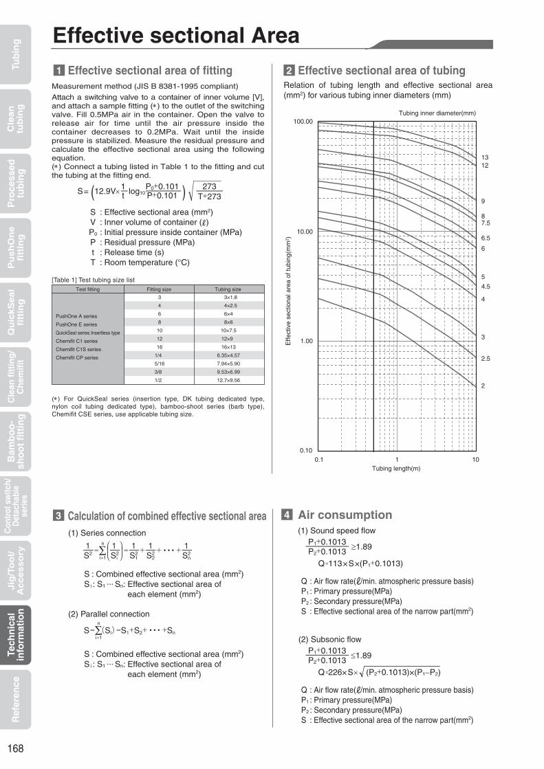
168
Tub
ing
Cle
an
tub
ing
Pu
sh
On
efi
ttin
gQ
uic
kS
ea
lfi
ttin
gB
amb
oo
-sh
oo
t fi
ttin
gC
ontr
ol s
witc
h/D
etac
habl
ese
ries
Cle
an f
itti
ng
/C
hem
ifit
Jig
/To
ol/
Accesso
ryR
efer
ence
Pro
cess
edtu
bin
gTe
chn
ical
info
rmat
ion
Effective sectional Area
Measurement method (JIS B 8381-1995 compliant)
Attach a switching valve to a container of inner volume [V], and attach a sample fitting (∗) to the outlet of the switching valve. Fill 0.5MPa air in the container. Open the valve to release air for time until the air pressure inside the container decreases to 0.2MPa. Wait until the inside pressure is stabilized. Measure the residual pressure and calculate the effective sectional area using the following equation.(∗) Connect a tubing listed in Table 1 to the fitting and cut the tubing at the fitting end.
1
3 4
Relation of tubing length and effective sectional area (mm2) for various tubing inner diameters (mm)
Effective sectional area of fitting 2 Effective sectional area of tubing
Calculation of combined effective sectional area Air consumption
Test fitting Fitting size
PushOne A series
PushOne E series
QuickSeal series Insertless type
Chemifit C1 series
Chemifit C1S series
Chemifit CP series
3
4
6
8
10
12
16
1/4
5/16
3/8
1/2
Tubing size
3×1.8
4×2.5
6×4
8×6
10×7.5
12×9
16×13
6.35×4.57
7.94×5.90
9.53×6.99
12.7×9.56
[Table 1] Test tubing size list
SVP0
PtT
: Effective sectional area (mm2): Inner volume of container ( ): Initial pressure inside container (MPa): Residual pressure (MPa): Release time (s): Room temperature (°C)
(1) Series connection
S= (12.9V× log10 ) 273T+273
P0+0.101P+0.101
1t
S : Combined effective sectional area (mm2)
S i : S1 ... Sn: Effective sectional area of each element (mm2)
S : Combined effective sectional area (mm2)Si : S1 ... Sn: Effective sectional area of each element (mm2)
(2) Parallel connection
(1) Sound speed flow
(2) Subsonic flow
Q=226×S× (P2+0.1013)×(P1−P2)
Tubing length(m)
Tubing inner diameter(mm)
(∗) For QuickSeal series (insertion type, DK tubing dedicated type, nylon coil tubing dedicated type), bamboo-shoot series (barb type), Chemifit CSE series, use applicable tubing size.
Effe
ctiv
e se
ctio
nal a
rea
of tu
bing
(mm
2 )
≥1.89P1+0.1013P2+0.1013
Q=113×S×(P1+0.1013)
Q : Air flow rate( /min. atmospheric pressure basis)P1 : Primary pressure(MPa)P2 : Secondary pressure(MPa)S : Effective sectional area of the narrow part(mm2)
1.89P1+0.1013P2+0.1013
Q : Air flow rate( /min. atmospheric pressure basis)P1 : Primary pressure(MPa)P2 : Secondary pressure(MPa)S : Effective sectional area of the narrow part(mm2)
≥
100.00
10.00
1.00
0.100.1 1 10
13 12
9
8 7.5
6.5
6
5
4.5
4
3
2.5
2

169
Tub
ing
Cle
an
tub
ing
Pu
sh
On
efi
ttin
gQ
uic
kS
ea
lfi
ttin
gB
amb
oo
-sh
oo
t fi
ttin
gC
ontr
ol s
witc
h/D
etac
habl
ese
ries
Cle
an f
itti
ng
/C
hem
ifit
Jig
/To
ol/
Accesso
ryR
efer
ence
Pro
cess
edtu
bin
gTe
chn
ical
info
rmat
ion
Negative Pressure Performance List
(∗1) Influence of permeation, etc., on the operation fluid should be checked under your company's use conditions.(∗2) Other control and switch products (speed controller, ball valve, throttle valve, and valve built-in connector) cannot be used at a negative pressure.
About explanations of negative pressure performance In pages introducing each product, the unit of negative pressure performance is based on atmospheric pressure, which is gauge pressure. Therefore, negative pressure performance is indicated by adding a minus sign in front.In addition, the character "G" is omitted on signage of the unit.
(Unit conversion) −101.325kPa G = −760mmHg G = −760Torr G
Shaded area : Usable
Product name
Unit
Tubing (*1)(U5,U2,U1,N5,N2,N1,TES,PL,PN,TA,TP,FS,FW,FWU,UE,DK,PB,UC,USC,UMC,UML,S)
PushOne series
QuickSeal series
Bamboo-shoot fitting series
Chemifit series
Switch and detachable series (∗2)
A series
E series
Insertion type
Insertless type
Barb type
C1 series
C1S series
CSE series
CP series
Q.D.C 101 series
Q.D.C 103 series
Miniature valve
Atmospheric pressureAbsolute vacuum
0kPa G
101.325kPa abs
−98.642kPa G
2.683kPa abs
−99.975kPa G
1.350kPa abs
−101.294kPa G
0.030kPa abs
−101.325kPa G
0kPa abs
Gaugepressure[Gauge]
Standard
Absolutepressure
[abs]

170
Tub
ing
Cle
an
tub
ing
Pu
sh
On
efi
ttin
gQ
uic
kS
ea
lfi
ttin
gB
amb
oo
-sh
oo
t fi
ttin
gC
ontr
ol s
witc
h/D
etac
habl
ese
ries
Cle
an f
itti
ng
/C
hem
ifit
Jig
/To
ol/
Accesso
ryR
efer
ence
Pro
cess
edtu
bin
gTe
chn
ical
info
rmat
ion
Preparation before pipingPrepare a tube cutter and attachment tools of an appropriate size.
Tube cutterproduct number
Applicable tubingouter diameter(mm)
TC01
TC04
HC03
∼13(1/2inch)
∼16(5/8inch)
∼20(3/4inch)
[Table 1] Applicable tubing size of tube cutter
Thread size(JIS B 0205 : 2001)(JIS B 0203 : 1999)
Recommended tightening torque(N . m)
M3
M5
M6
R1/8
R1/4
R3/8
R1/2
0.7
1.2
2.0
3.0∼5.0
7.0∼9.0
18.0∼20.0
20.0∼22.0
[Table 2] Recommended tightening torque for PushOne series
(Note)
Instruction Manual for PushOneTM A and E Series
Caution:
Caution:
Select an appropriate tube cutter TC01, TC04 or HC03 for the tubing size. See [Table 1] for the applicable tubing size of each cutter.
Seal-processed thread of the PushOne series does not require sealing tape.
Close the tube cutter blades when not using the cutter.
Check that the fitting and the tubing meet the specifications of the piping environment. Incorrect selection of products may cause an extremely serious accident.
Attaching a fitting (re-attaching a fitting)Use appropriate-size attachment tools to attach a fitting. Tighten the fitting to the recommended tightening torque given in [Table 2.]
(Note)
Caution:
Caution:
Caution:
Usually, processed seal can be used two or three times.
When the processed seal becomes less effective, bind sealing tape around the seal-processed thread. The sealing tape should be bound 2-2.5 times in the correct direction, leaving one or two ridges unsealed from the end.
(Note)The insertion length of the tubing is summarized in [Table 3]. See the table for reference.
Before inserting a tubing, mark the tubing at the insertion length from the end so that you can check if the tubing is properly inserted. See [Table 3] for the tubing insertion length. If the mark comes to the edge of the release sleeve and if the tubing would not be pulled out easily, the tubing connection work is completed.
The millimeter and the inch size types of the PushOne E series are distinguished by a punch mark (of tubing size) on the release sleeve and the release sleeve color (millimeter: blue, inch: white). φ8 and φ5/16 types share a release sleeve mold with the same size mark, and therefore should be distinguished only by the release sleeve color.
When a hexagon spanner is used for hexagon socket connector, be sure not to touch the lock ring part or the tubing seal part of the fitting to prevent disconnection of tubing and leakage.
Over-tightening of M thread could break the thread part or deform gasket, causing leakage. Be sure to tighten the thread to the recommended torque.
When reattaching a fitting, be careful not to let the sealing material of the seal-processed part contaminate operating fluid.
Cut the tubingCutting tubes at a right angle with a tube cutter. Clean the surfaces of tubes before cutting. Select undented, undamaged, well-shaped tubes.
Caution: Do not leave dirt, dents, damage, deformations, burrs, or fluff on the cut surface. Do not cut tubes at a titled angle. The seal of the connection could be damaged, causing leakage.
Connect tubing and finishing work.Insert the tubing steadily straight into the fitting until the tubing reaches the end. After inserting the tubing, try to pull it out gently and check that it will not pop out.
1
2
3
4

171
Tub
ing
Cle
an
tub
ing
Pu
sh
On
efi
ttin
gQ
uic
kS
ea
lfi
ttin
gB
amb
oo
-sh
oo
t fi
ttin
gC
ontr
ol s
witc
h/D
etac
habl
ese
ries
Cle
an f
itti
ng
/C
hem
ifit
Jig
/To
ol/
Accesso
ryR
efer
ence
Pro
cess
edtu
bin
gTe
chn
ical
info
rmat
ion
[Table 3] Insertion length of PushOne series tubingApplicable tubing
outer diameter(mm)Insertion length of tubing
(mm)
3
4
6
4
6
8
10
12
16
6.35(1/4inch)
7.94(5/16inch)
9.53(3/8inch)
12.70(1/2inch)
PushOneseries
PushOne A seriesMini type
PushOne A seriesPushOne E series
9
10
11
13
15
16
19
20
27
15
16
19
21
Tubing materialOuter diameter tolerance of tubing
(mm)
Polyurethane tubing
Nylon tubing
±0.1
±0.1
[Table 4] Outer diameter tolerance of applicable tubing
Caution:
Caution:
An improperly inserted tubing may cause disconnection or leakage.If you use other manufacturers' tubes to make the connection, check that the outer diameter tolerance of the tubing lies in the range of the size tolerance given in [Table 4]. If it does not, leakage may occur.
Caution:
Caution:
If you try to pull out or twist a tubing without re-inserting it until it reaches the end and without sufficiently pressing the release sleeve, the tubing will not come out.
Be sure to make the internal pressure zero before disconnecting a tubing.
Disconnect tubingRe-insert the tubing into the fitting body until the tubing reaches the end, and pull it out straight from the fitting while pushing the release sleeve evenly with two fingers. Do not twist the tubing when pulling it out.
Caution: In the event internal pressure or heat changes the inner and outer diameters of tubing, replace the tubing with a new one.
Re-connect tubingRepeat the steps from “3. Cut the tubing”. If you re-connect a disconnected tubing, cut off the tip where a claw pattern is left. Also, confirm that there is no dirt, dents, damage, or deformations on the tubing.
5
6

172
Tub
ing
Cle
an
tub
ing
Pu
sh
On
efi
ttin
gQ
uic
kS
ea
lfi
ttin
gB
amb
oo
-sh
oo
t fi
ttin
gC
ontr
ol s
witc
h/D
etac
habl
ese
ries
Cle
an f
itti
ng
/C
hem
ifit
Jig
/To
ol/
Accesso
ryR
efer
ence
Pro
cess
edtu
bin
gTe
chn
ical
info
rmat
ion
Preparation before pipingPrepare a tube cutter, attachment tools of an appropriate size and sealing tape.
(Note)
Instruction Manual for QuickSeal Series
Caution:
Caution:
Select an appropriate tube cutter TC01, TC04 or HC03 for the tubing size. See [Table 1] for the applicable tubing size of each cutter.
The seal-processed brass connector of the QuickSeal series doesnot require sealing tape.
Close the tube cutter blades when not using the cutter.
Check that the fitting and the tubing meet the specifications of the piping environment. Incorrect selection of products may cause an extremely serious accident.
Winding of sealant tapeThe sealing tape should be bound 2-2.5 times in the correct direction, leaving one or two ridges unsealed from the end. Seal-processed brass connector of the QuickSeal series does not require sealing tape.
(Note)
Caution:
Caution:
When the seal on brass connector becomes less effective, bind sealing tape around the seal-processed thread.
Usually, a processed seal can be used two or three times.
(Note)When you cut a DK tubing, be sure not to deform the tubing tip. An old blade cutter may cause deformation. Use a new tube cutter in this case.
Use hose cutter HC01 for cutting S3/4-type nylon coil tubing.
When reattaching a seal-processed product, be careful not to let the sealing material contaminate the operating fluid.
When reattaching a fitting other than seal-processed products, remove the old seal on the thread and bind with new sealing tape. The old sealing tape could contaminate the operating fluid and cause problems.
MountingUse appropriate-size attachment tools to attach a fitting. Tighten the fitting to the recommended tightening torque given in [Table 2] .
Caution:
Caution:
The thread may become seized with high heat in the stainless type of fitting. Tighten slowly to prevent the thread from seizing.
Quick rotation of a torque wrench to tighten a swivel nut fitting generates small pressure on the sheet surface and could cause leakage.
Caution: Do not leave dirt, dents, damage, deformations, burrs, or fluff on the cut surface. Do not cut the tubes at a titled angle. The seal of the connection, causing leakage.
Cut the tubingCutting tubes at a right angle with a tube cutter. Clean the surfaces of tubes before cutting. Select undented, undamaged, well-shaped tubes.
[Table 1] Applicable tubing size of tubing cutter
Thread size(JIS B 0203 : 1999)(JIS B 0202 : 1999)
Recommended tightening torque(N . m)
R1/8
R1/4
R3/8
R1/2
G1/8
G1/4
G3/8
G1/2
3.0∼5.0
7.0∼9.0
18.0∼20.0
20.0∼22.0
15
25
50
60
[Table 2] Recommended tightening torque for QuickSeal series
(Attaching swivel nut)
Insert tubing into the nut and the sleeveInsert tubing into the nut and the sleeve as shown in the photograph. The sleeve has a correct insertion direction. The thicker part should face the tubing end direction. Leave a space of more than 1cm long between the sleeve and the tubing end.
Adapter
Tightening direction
Spanner for fixingSpanner for tightening
NutBody
First, tighten by hand. Then tighten the nut with a torque wrench while fixing the nipple with a spanner.
1
Tube cutterproduct number
Applicable tubingouter diameter(mm)
TC01
TC04
HC03
∼13(1/2inch)
∼16(5/8inch)
∼20(3/4inch)
2
3
4
5

173
Tub
ing
Cle
an
tub
ing
Pu
sh
On
efi
ttin
gQ
uic
kS
ea
lfi
ttin
gB
amb
oo
-sh
oo
t fi
ttin
gC
ontr
ol s
witc
h/D
etac
habl
ese
ries
Cle
an f
itti
ng
/C
hem
ifit
Jig
/To
ol/
Accesso
ryR
efer
ence
Pro
cess
edtu
bin
gTe
chn
ical
info
rmat
ion
Caution:
Caution:
Caution:
The thread may become seized with high heat in the stainless type of fitting. Tighten slowly to prevent seizing of thread.
The appropriate number of rotations for tightening nuts varies depending on the size and material of sleeve. Be sure to check the appropriate number of rotations.
For use of the QuickSeal series at a high temperature within the working temperature range, tighten the nut periodically. If the nut cannot be tightened further, cut off the tubing end as well as the sleeve and repeat the steps from “4. Cut the tubing” with a new sleeve.
[Table 5] Appropriate number of rotations for tightening nuts
4
6
8
10
12
16
3.18(1/8inch)
4.76(3/16inch)
6.35(1/4inch)
7.94(5/16inch)
9.53(3/8inch)
12.70(1/2inch)
15.88(5/8inch)
2∼2.5
2∼2.5
2∼2.5
2∼2.5
2∼2.5
2∼2.5
2∼3
2∼3
2∼3
2∼3
2∼3
2∼3
2.5∼3
Sleeve material
Nylon sleeve
Applicable tubingouter diameter
(mm)
Appropriate numberof rotations
for tightening nuts
Caution: If you use other manufacturers' tubes to make the connection, check that the outer diameter tolerance of the tubing lies in the range of the size tolerance given in [Table 4]. If it does not, leakage may occur. An improperly inserted tubing may cause disconnection or leakage.
(Note)The millimeter and the inch size types of the QuickSeal series insertion type are distinguished by a punch mark (of tubing size) on the fitting body, the cut on the nut, and the sleeve color (millimeter: milky white, inch: black).
Use a tubing insertion part (SI 3/4) for 3/4-size nylon coil tubing QuickSeal fitting.
(Note)The insertion length of the tubing is summarized in [Table 3]. See the table for reference.
Insert tubingInsert the tubing into the fitting body until the tubing reaches the end.
[Table 3] Insertion length of QuickSeal series tubing
4
6
8
10
12
16
3.18(1/8inch)
4.76(3/16inch)
6.35(1/4inch)
7.94(5/16inch)
9.53(3/8inch)
12.70(1/2inch)
15.88(5/8inch)
15
15
16
17
18
23
15
15
15
16
17
18
23
Applicable tubingouter diameter
(mm)
Insertion lengthof tubing
(mm)Type
Insertion type
(group 4)
DK tubing
dedicated
type
Insertion type
(group 1)
Insertion type
(group 2)
3.18(1/8inch)
4
6
8
10
12
21
14
14
15
18
19
Insertion type (group 2)
Insertless type
Tightening nuts by hand
Tubing materialOuter diameter tolerance of tubing
(mm)
Polyurethane tubing
Nylon tubing
±0.1
±0.1
[Table 4] Outer diameter tolerance of applicable tubing
Tightening nuts and finishing workTighten the hand tightened nut with a spanner or a crescent wrench according to the appropriate number of rotations for tightening the nuts given in [Table 5] .
(Note)
Before inserting a tubing, mark the tubing at the insertion length from the end so that you can check if the tubing is properly inserted.If the marking moves 1-2mm from the sleeve end by tightening the nut, it is a sign that the nut is properly tightened.
Re-connect tubingCut off the tubing end as well as the sleeve and repeat the steps from “4. Cut the tubing” with a new sleeve. Confirm that there is no dirt, dents, damage, and or deformations on the tubing surface.
(Note)
Caution:
If you reuse a nut, check that the nut is not damaged. A damaged nut could cause problems such as improper tightening or leakage.
In the event internal pressure or heat changes the inner and outer diameters of tubing, replace the tubing with a new one.
Brass type
Millimetersize
Inchsize
Millimetersize
Inchsize
Stainless type
Mar
king
Type
S3/16
S1/4
S3/8
S1/2
S3/4
16
18
22
29
31
Applicable tubingproduct number
Nylon coil tubing
dedicated type
Type
S3/16
S1/4
S3/8
S1/2
S3/4
1.5∼2
2∼2.5
2∼2.5
2.5∼3
2∼2.5
Nylon coil tubing
dedicated type
6
Applicable tubingouter diameter
(mm)
Insertion lengthof tubing
(mm)
Insertion lengthof tubing
(mm)Applicable tubingproduct number
TypeAppropriate number
of rotationsfor tightening nuts
7
8
9
It is recommended to mark the nut and the fitting body at the hand tightened position in order to check the number of ro ta t ions of the nut.
(Note)Tighten the nut by hand.
4
6
8
10
12
3.18 (1/8inch)
4.76 (3/16inch)
6.35 (1/4inch)
7.94 (5/16inch)
9.53 (3/8inch)
12.70 (1/2inch)
1∼1.5
1∼1.5
1∼1.5
1.5∼2
1.5∼2
1∼1.5
1∼1.5
1∼1.5
0.75∼1.25
0.75∼1.25
0.75∼1.25
Applicable tubingouter diameter
(mm)
Appropriate numberof rotations
for tightening nutsSleeve material
Brass sleeve

174
[Table 2] Insertion length of Chemifit C1 series tubing
3
4
6
8
10
12
3.18(1/8inch)
6.35(1/4inch)
9.53(3/8inch)
12.70(1/2inch)
11
14
15
16
19
20
11
16
20
23
Series name
Chemifit C1 series
TC01
TC04
HC03
∼13(1/2inch)
∼16(5/8inch)
∼20(3/4inch)
[Table 1] Applicable tubing size of tube cutter
Tube cutterproduct number
Applicable tubingouter diameter(mm)
Applicable tubingouter diameter(mm)
Insertion length of tubing(mm)
Tub
ing
Cle
an
tub
ing
Pu
sh
On
efi
ttin
gQ
uic
kS
ea
lfi
ttin
gB
amb
oo
-sh
oo
t fi
ttin
gC
ontr
ol s
witc
h/D
etac
habl
ese
ries
Cle
an f
itti
ng
/C
hem
ifit
Jig
/To
ol/
Accesso
ryR
efer
ence
Pro
cess
edtu
bin
gTe
chn
ical
info
rmat
ion
Preparation before pipingPrepare a tube cutter and crescent wrench, and sealing tape.
(Note)
Instruction Manual for ChemitTM C1 Series
Caution:
Caution:
Select an appropriate tube cutter TC01, TC04 or HC03 for the tubing size. See [Table 1] for the applicable tubing size of each cutter.
Close the tube cutter blades when not using the cutter.
Check that the fitting and the tubing meet the specifications of the piping environment. Incorrect selection of products may cause an extremely serious accident.
Connect tubing and finish work.Insert the tubing steadily straight into the fitting until the tubing reaches the end. After inserting the tubing, try to pull it out gently and check that it will not pop out.
(Note)
Caution:
Caution:
Caution:
The millimeter and the inch size types of the Chemifit C1 series are distinguished by a punch mark of tubing size on the release sleeve.
The insertion length of the tubing is summarized in [Table 2]. See the table for reference.
An improperly inserted tubing may cause disconnection or leakage.
Chemifit C1 series has a resin thread, which allows stress relaxation relatively easily compared to metal thread. In some cases oozing leakage occurs. In particular at a high temperature, tighten the fitting periodically. If the fitting cannot be tightened further, replace it with a new one.
If you use other manufacturers’ tubes to make the connection, use a tubing with a size tolerance within ±0.1mm. Otherwise, leakage may occur.
Winding of sealant tapeThe sealing tape should be bound 2-2.5 times in the correct direction, leaving one or two ridges unsealed from the end.
Caution:
Caution:
Mounted fittingsFirst, tighten a fitting by hand. Then tighten it about two turns with a crescent wrench.
Over-tightening could damage the resin thread and cause deformation and leakage.
Use a crescent wrench to tighten the hexagonal (HEX) part, which is made of resin. Using a spanner could cause damage to the HEX part.
Caution:
Cut the tubingCutting tubes at a right angle with a tube cutter. Clean the surfaces of tubes before cutting. Select undented, undamaged, well-shaped tubes.
Do not leave dirt, dents, damage, deformations, burrs, or fluff on the cut surface. Do not cut tubes at a titled angle. The seal of the connection could be damaged, causing leakage.
1 4
5
2
3

175
Tub
ing
Cle
an
tub
ing
Pu
sh
On
efi
ttin
gQ
uic
kS
ea
lfi
ttin
gB
amb
oo
-sh
oo
t fi
ttin
gC
ontr
ol s
witc
h/D
etac
habl
ese
ries
Cle
an f
itti
ng
/C
hem
ifit
Jig
/To
ol/
Accesso
ryR
efer
ence
Pro
cess
edtu
bin
gTe
chn
ical
info
rmat
ion
Disconnect tubingRe-insert the tubing into the fitting body until the tubing reaches the end, and pull it out straight from the fitting while pushing the release sleeve evenly with two fingers. Do not twist the tubing when pulling it out.
Caution:
Caution:
Re-connect tubingRepeat the steps from “4. Cut the tubing”. If you re-connect a disconnected tubing, cut off the tip where a claw pattern is left. Also, confirm that there is no dirt, dents, damage, or deformations on the tubing.
If you try to pull out or twist a tubing without re-inserting it until it reaches the end and without sufficiently pressing the release sleeve, the tubing will not come out.
Be sure to make the internal pressure zero before disconnecting a tubing.
Caution: In the event internal pressure or heat changes the inner and outer diameters of tubing, replace the tubing with a new one.
6
7

176
TC01
TC04
HC03
∼13(1/2inch)
∼16(5/8inch)
∼20(3/4inch)
[Table 1] Applicable tubing size of tube cutter
Tube cutterproduct number
Applicable tubingouter diameter(mm)
Tub
ing
Cle
an
tub
ing
Pu
sh
On
efi
ttin
gQ
uic
kS
ea
lfi
ttin
gB
amb
oo
-sh
oo
t fi
ttin
gC
ontr
ol s
witc
h/D
etac
habl
ese
ries
Cle
an f
itti
ng
/C
hem
ifit
Jig
/To
ol/
Accesso
ryR
efer
ence
Pro
cess
edtu
bin
gTe
chn
ical
info
rmat
ion
Prepare a tube cutter, attachment tools of an appropriate size and sealing tape.
(Note)
Caution:
Caution:
Select an appropriate tube cutter TC01, TC04 or HC03 for the tubing size. See [Table 1] for the applicable tubing size of each cutter.
Close the tube cutter blades when not using the cutter.
Check that the fitting and the tubing meet the specifications of the piping environment. Incorrect selection of products may cause an extremely serious accident.
Caution: When reattaching the fitting body, remove the old seal on the thread and bind with new sealing tape. The old sealing tape could contaminate the operating fluid and cause problems.
The sealing tape should be bound 2-2.5 times in the correct direction, leaving one or two ridges unsealed from the end.
Caution:
Caution:
Use appropriate-size attachment tools to attach a fitting. Tighten the fitting to the recommended tightening torque given in [Table 2].
Tighten slowly to prevent the thread from seizing.
Over-tightening of M thread could break the thread or deform the gasket, causing leakage. Be sure to tighten it to the recommended torque.
Caution:
Cutting tubes at a right angle with a tube cutter. Clean the surfaces of tubes before cutting. Select undented, undamaged, well-shaped tubes.
Do not leave dirt, dents, damage, deformations, burrs, or fluff on the cut surface. Do not cut tubes at a titled angle. The seal of the connection could be damaged, causing leakage.
Thread size(JIS B 0205 : 2001)(JIS B 0203 : 1999)
Recommended tightening torque(N . m)
M5
R1/8
R1/4
R3/8
R1/2
1.2
3.0∼5.0
7.0∼9.0
18.0∼20.0
20.0∼22.0
[Table 2] Recommended tightening torque for Chemifit C1S series
Instruction Manual for ChemitTM C1S Series Preparation before piping1
Winding of sealant tape2 Cut the tubing4
Mounting3

177
Tub
ing
Cle
an
tub
ing
Pu
sh
On
efi
ttin
gQ
uic
kS
ea
lfi
ttin
gB
amb
oo
-sh
oo
t fi
ttin
gC
ontr
ol s
witc
h/D
etac
habl
ese
ries
Cle
an f
itti
ng
/C
hem
ifit
Jig
/To
ol/
Accesso
ryR
efer
ence
Pro
cess
edtu
bin
gTe
chn
ical
info
rmat
ion
(Note)
Caution:
Caution:
The millimeter and the inch size types of the Chemifit C1S series are distinguished by a punch mark of tubing size on the release sleeve.The insertion length of the tubing is summarized in [Table 3]. See the table for reference.
An improperly inserted tubing may cause disconnection or leakage.
If you use other manufacturers’ tubes to make the connection, use a tubing with a size tolerance within ±0.1mm. Otherwise, leakage may occur.
[Table 3] Insertion length of Chemifit C1S series tubing
Insert the tubing steadily straight into the fitting until the tubing reaches the end. After inserting the tubing, try to pull it out gently and check that it will not pop out.
Caution:
Caution:
If you try to pull out or twist a tubing without re-inserting it until it reaches the end and without sufficiently pressing the release sleeve, the tubing will not come out.
Be sure to make the internal pressure zero before disconnecting a tubing.
Re-insert the tubing into the fitting body until the tubing reaches the end, and pull it out straight from the fitting while pushing the release sleeve evenly with two fingers. Do not twist the tubing when pulling it out.
Caution: In the event internal pressure or heat changes the inner and outer diameters of tubing, replace the tubing with a new one.
Repeat the steps from “Cut the tubing”. If you re-connect a disconnected tubing, cut off the tip where a claw pattern is left. Also, confirm that there is no dirt, dents, damage, or deformations on the tubing.
Connect tubing and finishing work
Disconnect tubing
Re-connect tubing
6
75
3
4
6
8
10
12
3.18(1/8inch)
6.35(1/4inch)
9.53(3/8inch)
12.70(1/2inch)
11
14
15
16
19
20
11
16
20
23
Series name
Chemifit C1S series
Applicable tubingouter diameter(mm)
Insertion length of tubing(mm)

178
TC01
TC04
HC03
∼13(1/2inch)
∼16(5/8inch)
∼20(3/4inch)
[Table 1] Applicable tubing size of tube cutter
Tube cutterproduct number
Applicable tubingouter diameter(mm)
Prepare a tube cutter, attachment tools of an appropriate size and sealing tape.
(Note)
Caution:
Caution:
Select an appropriate tube cutter TC01, TC04 or HC03 for the tubing size. See [Table 1] for the applicable tubing size of each cutter.
Close the tube cutter blades when not using the cutter.
Check that the fitting and the tubing meet the specifications of the piping environment. Incorrect selection of products may cause an extremely serious accident.
Caution: When reattaching the fitting body, remove the old seal on the thread and bind with new sealing tape. The old sealing tape could contaminate the operating fluid and cause problems.
The sealing tape should be bound 2-2.5 times in the correct direction, leaving one or two ridges unsealed from the end.
Caution:
Use appropriate-size attachment tools to attach a fitting. Tighten the fitting to the recommended tightening torque given in [Table 2].
Tighten slowly to prevent the thread from seizing.
Caution:
Cutting tubes at a right angle with a tube cutter. Clean the surfaces of tubes before cutting. Select undented, undamaged, well-shaped tubes.
Insert tubing into the assembly nut in such a direction that the thread part faces the tubing end.
Do not leave dirt, dents, damage, deformations, burrs, or fluff on the cut surface. Do not cut tubes at a titled angle. The seal of the connection could be damaged, causing leakage.
Thread size(JIS B 0203 : 1999)
Recommended tightening torque(N . m)
R1/8
R1/4
R3/8
R1/2
3.0∼5.0
7.0∼9.0
18.0∼20.0
20.0∼22.0
[Table 2] Recommended tightening torque for Chemifit CSE series
Instruction Manual for ChemitTM CSE Series Preparation before piping1
Cut the tubing4
Insert tubing into the assembly nut5
Winding of sealant tape2
Mounting3Tub
ing
Cle
an
tub
ing
Pu
sh
On
efi
ttin
gQ
uic
kS
ea
lfi
ttin
gB
amb
oo
-sh
oo
t fi
ttin
gC
ontr
ol s
witc
h/D
etac
habl
ese
ries
Cle
an f
itti
ng
/C
hem
ifit
Jig
/To
ol/
Accesso
ryR
efer
ence
Pro
cess
edtu
bin
gTe
chn
ical
info
rmat
ion

179
Insert tubing6
(Note)
(Note)The insertion length of the tubing is summarized in [Table 3]. See the table for reference.
The millimeter and the inch size types of the Chemifit CSE series are distinguished by a boss at the internal sleeve as shown on the right.
Tighten the hand-tightened nut with a spanner or a crescent wrench until the nut reaches the fitting body.
If the assembly nut touches the fitting body, the assembly work is completed.
Cut off the tubing end and repeat the steps from “4. Cut the tubing”. Confirm that there is no dirt, dents, damage, or deformations on the tubing surface.
Applicable tubing outer×
inner diameters (mm)Insertion length of tubing
(mm)
4×2
6×4
8×5
8×6
10×6.5
10×8
12×9
12×10
19×16
6.35×4.57(1/4inch)∗
9.53×6.99(3/8inch)∗
12.70×9.56(1/2inch)∗
5.5
7.0
7.5
7.5
8.5
8.5
10.0
10.0
12.5
7.0
8.5
10.5
[Table 3] Insertion length of Chemifit CSE series tubing
Cross section of internal sleeve
Caution:
Caution:
Insert the tubing into the fitting body until the tubing reaches the end.
If you use other manufacturers’ tubes to make the connection, use a tubing with a size tolerance within ±0.1mm. Otherwise, leakage may occur.
An improperly inserted tubing may cause disconnection or leakage.
If you reuse an assembly nut, check that the internal sleeve is not damaged. A damage assembly nut could cause problems such as leakage.
Caution:
Caution:
Be sure to make the internal pressure zero before disconnecting a tubing.
In the event internal pressure or heat changes the inner and outer diameters of tubing, replace the tubing with a new one.Tighten the assembly nut by hand.
∗Tube outer diameter
Millimeter size Inch size
Projection for distinction
Tightening nuts by hand7
Tightening nuts 8
Tightening completed9
Re-connect tubing10
Millimeter size Inch size
Tub
ing
Cle
an
tub
ing
Pu
sh
On
efi
ttin
gQ
uic
kS
ea
lfi
ttin
gB
amb
oo
-sh
oo
t fi
ttin
gC
ontr
ol s
witc
h/D
etac
habl
ese
ries
Cle
an f
itti
ng
/C
hem
ifit
Jig
/To
ol/
Accesso
ryR
efer
ence
Pro
cess
edtu
bin
gTe
chn
ical
info
rmat
ion

180
TC01
TC04
HC03
∼13(1/2inch)
∼16(5/8inch)
∼20(3/4inch)
Tube cutterproduct number
Applicable tubingouter diameter(mm)
Tub
ing
Cle
an
tub
ing
Pu
sh
On
efi
ttin
gQ
uic
kS
ea
lfi
ttin
gB
amb
oo
-sh
oo
t fi
ttin
gC
ontr
ol s
witc
h/D
etac
habl
ese
ries
Cle
an f
itti
ng
/C
hem
ifit
Jig
/To
ol/
Accesso
ryR
efer
ence
Pro
cess
edtu
bin
gTe
chn
ical
info
rmat
ion
Insert the tubing into the fitting body until the tubing reaches the end.
Prepare a tube cutter, a crescent wrench and sealing tape.
(Note)
Caution:
Caution:
Select an appropriate tube cutter TC01, TC04 or HC03 for the tubing size. See [Table 1] for the applicable tubing size of each cutter.
Close the tube cutter blades when not using the cutter.
Check that the fitting and the tubing meet the specifications of the piping environment. Incorrect selection of products may cause an extremely serious accident.
(Note)
Caution:
Caution:
The millimeter and the inch size types of the Chemifit CP series are distinguished by the shape of the sleeve. The insertion length of the tubing is summarized in [Table 2]. See the table for reference.
If you use other manufacturers’ tubes to make the connection, use a tubing with a size tolerance within ±0.1mm. Otherwise, leakage may occur.
An improperly inserted tubing may cause disconnection or leakage.
The sealing tape should be bound 2-2.5 times in the correct direction, leaving one or two ridges unsealed from the end.
Caution:
Caution:
First, tighten a fitting by hand. Then tighten it about two turns with a crescent wrench.
Over-tightening could damage the resin fittings body and cause deformation and leakage.
Use a crescent wrench to tighten the hexagonal (HEX) part, which is made of resin. Using a spanner could cause damage to the HEX part.
Caution:
Cutting tubes at a right angle with a tube cutter. Clean the surfaces of tubes before cutting. Select undented, undamaged, well-shaped tubes.
Do not leave dirt, dents, damage, deformations, burrs, or fluff on the cut surface. Do not cut tubes at a titled angle. The seal of the connection could be damaged, causing leakage.
Insert tubing first into nut, then into sleeve. Leave a space of more than 1cm long between the tubing end and the sleeve. (It is recommended to use an insertion part for flexible tubes such as polyolefin tubing.)
SleeveNut
Insertion part
Millimeter size Inch size
Instruction Manual for ChemitTM CP Series
Insert tubing6
Preparation before piping1 Cut the tubing4
Insert tubing into nut and sleeve (using insertion part)5
Winding of sealant tape2
Mounting3
[Table 1] Applicable tubing size of tube cutter

181
Tub
ing
Cle
an
tub
ing
Pu
sh
On
efi
ttin
gQ
uic
kS
ea
lfi
ttin
gB
amb
oo
-sh
oo
t fi
ttin
gC
ontr
ol s
witc
h/D
etac
habl
ese
ries
Cle
an f
itti
ng
/C
hem
ifit
Jig
/To
ol/
Accesso
ryR
efer
ence
Pro
cess
edtu
bin
gTe
chn
ical
info
rmat
ion
Caution: Use a crescent wrench to tighten the hexagonal (HEX) part, which is made of resin. Using a spanner could cause damage to the HEX part.
Caution: The Chemfit CP series has a resin thread, which allows stress relaxation relatively easily compared to metal thread. In some cases leakage occurs. In particular at a high temperature, tighten the fitting periodically. If the fitting cannot be tightened further, replace it with a new one.
Caution:
Caution:
Caution:
Be sure to make the internal pressure zero before disconnecting a tubing.
The Chemifit CP series is made of resin, hence the nut and body could be deformed. Confirm that the nut and body are not damaged. A damaged nut and body would cause leakage.
In the event internal pressure or heat changes the inner and outer diameters of tubing, replace the tubing with a new one.
[Table 2] Insertion length of Chemifit CP series tubing
Applicable tubingouter diameter(mm)
Insertion length of tubing(mm)
4
6
8
10
12
6.35(1/4 inch)
9.53(3/8 inch)
12.70(1/2 inch)
16
18
20
25
29
18
25
29
[Table 3] Space between the nut and the fitting body of the Chemifit CP series
0.5
1.0
2.5
3.5
3.5
1.0
1.0
2.5
4
6
8
10
12
6.35(1/4 inch)
9.53(3/8 inch)
12.70(1/2 inch)
1
1
1.5
2
2
1
1
1.5
Space between the nut andthe fitting body(mm)
Applicable tubingouter diameter(mm)
Remaining numberof ridges
Tighten the nut by hand with the tubing being inserted to the fitting body.
Tighten the hand-tightened nut 1.5-2 turns with a crescent wrench.
If there is an appropriate space left between the nut and the fitting body as described in [Table 3], the assembly work is completed.
Cut off the tubing end and repeat the steps from “4. Cut the tubing” with a new sleeve (and insertion part). Confirm that there is no dirt, dents, damage, or deformations on the tubing surface.
Tightening nuts by hand7
Tightening nuts 8
Tightening completed9
Re-connect tubing10

182
Tub
ing
Cle
an
tub
ing
Pu
sh
On
efi
ttin
gQ
uic
kS
ea
lfi
ttin
gB
amb
oo
-sh
oo
t fi
ttin
gC
ontr
ol s
witc
h/D
etac
habl
ese
ries
Cle
an f
itti
ng
/C
hem
ifit
Jig
/To
ol/
Accesso
ryR
efer
ence
Pro
cess
edtu
bin
gTe
chn
ical
info
rmat
ion
Make the residual pressure on the coupler side zero. Check that there is no foreign matter in the connection part. Then insert the nipple to the coupler without pulling the sleeve on the coupler.
Instruction Manual for Q.D.C 101 and 103 Series
101 series 103 series
Warning:
Caution:
Caution:
Caution:
(Note)See instruction manuals of appropriate specifications such as those of the PushOne series or QuickSeal series for handling thread and tubing connection parts.
Do not hit the valve head with a hammer, etc., to release residual pressure. It could break the valve and be extremely dangerous.
Connection without releasing residual pressure may break the valve.
Insert the nipple straight into the coupler.
When connecting a coupler and a nipple, do not hold the sleeve of the coupler.
Warning:
Caution:
Caution:
Caution:
Do not hit the valve head with a hammer, etc., to release residual pressure. It could break the valve and be extremely dangerous.
Connection without releasing residual pressure may break the valve.
Insert the nipple straight into the coupler.
When connecting a coupler and a nipple, do not hold the sleeve of the coupler.
Warning:Be aware that disconnection without releasing residual pressure not only causes damage to the product body but will also cause an accident.
Caution:
Caution:
Caution:
Rotational use of a coupler and a nipple is not recommended.
Use the product at a pressure lower than the maximum working pressure.
Do not use the product under too much bending stress or tension.
See instruction manuals of appropriate specifications such as those of the PushOne series or QuickSeal series for handling thread and tubing connection parts.
Caution:
Caution:
Caution:
Rotational use of a coupler and a nipple is not recommended.
Use the product at a pressure lower than the maximum working pressure.
Do not use the product under too much bending stress or tension.
Make the residual pressure on the coupler side zero. Pull out the coupler or the nipple to disconnect while pulling the sleeve of the coupler.
(Note)
Pull
Sleeve
Pull
Sleeve
Sleeve Sleeve
Connection of coupler and nipple1Make the residual pressure on the coupler side zero. Check that there is no foreign matter in the connection part. Then insert the nipple to the coupler without pulling the sleeve on the coupler.
Connection of coupler and nipple1
Disconnection of coupler and sleeve2
Warning:Be aware that fact that disconnection without releasing residual pressure not only causes damage to the product body but will also cause an accident.
Make the residual pressure on the coupler side zero. Pull out the coupler or the nipple to disconnect while pulling the sleeve of the coupler.
Disconnection of coupler and sleeve2

183
Tub
ing
Cle
an
tub
ing
Pu
sh
On
efi
ttin
gQ
uic
kS
ea
lfi
ttin
gB
amb
oo
-sh
oo
t fi
ttin
gC
ontr
ol s
witc
h/D
etac
habl
ese
ries
Cle
an f
itti
ng
/C
hem
ifit
Jig
/To
ol/
Accesso
ryR
efer
ence
Pro
cess
edtu
bin
gTe
chn
ical
info
rmat
ion
Prepare a tube cutter and an outer cover peeling cutter of appropriate type described in [Table 1]. Cut the tubes at a right angle with a tube cutter. Clean the surfaces of tubes before cutting. Select undented, undamaged, well-shaped tubes.
(Note)
Instruction Manual for FW/FWU Tubing Outer Cover Peeling Cutter (TC02, TC03, TC02U, TC03U)
Slowly insert the tubing while rotating to the contact surface in the cutter. When the tubing reaches the contact surface, pull it out slowly while rotating in the opposite direction.
Select an appropriate tube cutter TC01 or TC04 for the tubing size. See [Table 2] for the applicable tubing size of each cutter.
Contact the cutting surface of tubing with the blade in the insertion slot of the cutter.
Warning:
Caution:
Do not insert your finger into the insertion slot of the outer cover peeling cutter.
Do not use the cutter for tubes that Nitta does not designate.
Warning:Do not pull out a tubing with a strong force or rotate it rapidly. Doing so may cause damage to the cutter blade or the outer surface of the tubing.
Tube cutterproduct number
Applicable tubingouter diameter(mm)
TC01
TC04
∼13(1/2inch)
∼16(5/8inch)
[Table 2] Tubing size applicable for tube cutter
FW/FWU tubing outer diameter(mm)
Peeled outer cover length(mm)
6
8
10
12
15
16
19
20
[Table 3] Peeled outer cover length
[Table 1] Product number of applicable outer cover peeling cutter
6
8
10
12
6
8
10
12
TC02
TC03
TC02U
TC03U
Applicable tubing outerdiameter(mm)
Product number of applicableouter cover peeling cutter
Tubing type
FW
FWU
Remove the outer cover along the spiral cut line.
The peeling work is completed if the peeled cover length satisfies the requirement shown in [Table 3].
Pee
ling
dire
ctio
n
Peeled cover length
Preparation and cut the tubing1
Insert tubing2
Peeling outer cover and pulling out of tubing3
Removing outer cover4
Completing work5

184
Inte
rlock
ing
dire
ctio
n
Fixing pin hole
Tub
ing
Cle
an
tub
ing
Pu
sh
On
efi
ttin
gQ
uic
kS
ea
lfi
ttin
gB
amb
oo
-sh
oo
t fi
ttin
gC
ontr
ol s
witc
h/D
etac
habl
ese
ries
Cle
an f
itti
ng
/C
hem
ifit
Jig
/To
ol/
Accesso
ryR
efer
ence
Pro
cess
edtu
bin
gTe
chn
ical
info
rmat
ion
Notch
Hook
Pin fixing hole
Notch
Hook
Pin fixing hole
Hook
Instruction Manual for Tube Reel
2-1 Set the tubingPlace the reel body (B) as shown in the photograph, and a bundled tubing onto it. The tubing is bundled with tape. Place the tubing in such a direction so that the inside tubing end faces the clockwise direction.
Check the product number and applicable tubing sizes and confirm that you have all the necessary parts.
2-2 Position adjustment of inside tubing endPull out the inside tubing end from the bundle tape and rotate the tubing bundle for the tubing end to reach a hook of the reel body (B).
2-3 Fixing inside tubing end and setting reel plateCover the reel body with a reel plate (A) while inserting the position-adjusted tubing end into an inner-side hole (nearer one of two holes) of the reel plate.
2-4 Fixing reel plateAdjust the position of the reel plate (A) to match the positions of a notch of the reel plate (A) and the hook of the reel body (B). Rotate the reel plate (A) counterclockwise to interlock the notch and the hook. (Tip: Rotate the reel plate (A) pressing its center slightly.) Fit the positions of the fixing pin holes of the reel body (B) and the reel plate (A).
2-5 Insert fixing pinsInsert a reel fixing pin (C) into each of two fixing pin holes of the reel plate (A) to fix the plate with the reel body (B).
A
C
B
∗Product number of reel fixing pin is PTR-P.
Part
A
B
C∗
Name
Reel plate
Reel body
Reel fixing pin
Material
Polypropylene (P.P.)
Polypropylene (P.P.)
Polycarbonate + Nylon
Color
White
White
White
Quantity
1
1
2
(Note)It is recommended to cut the bundle tape somewhere inside and tape it temporarily onto the side of the bundle before you put the tubing bundle onto the reel body.
For setting PTR-2, substitute “reel plate (A)” with “reel body (B)” in the following instructions and follow the same procedure.
Specification of each part
Product number
PTR-1
PTR-2
Combination
A+B+C
B+B+C
Combination
Hook
Check of the type and sizes1
How to set PTR-12

185
Tub
ing
Cle
an
tub
ing
Pu
sh
On
efi
ttin
gQ
uic
kS
ea
lfi
ttin
gB
amb
oo
-sh
oo
t fi
ttin
gC
ontr
ol s
witc
h/D
etac
habl
ese
ries
Cle
an f
itti
ng
/C
hem
ifit
Jig
/To
ol/
Accesso
ryR
efer
ence
Pro
cess
edtu
bin
gTe
chn
ical
info
rmat
ion
2-6 Setting inside tubing endThe inside tubing end coming out of the reel plate (A) should be re-inserted in the other hole of the reel plate (A) as in the photograph. Or rotate the tubing bundle by hand to an appropriate position.
2-7 Completing workInsert the outside tubing end into the outer-side hole of the reel plate (A) and remove the bundle tape. The assembly of the tube reel is completed.

186
Tub
ing
Cle
an
tub
ing
Pu
sh
On
efi
ttin
gQ
uic
kS
ea
lfi
ttin
gB
amb
oo
-sh
oo
t fi
ttin
gC
ontr
ol s
witc
h/D
etac
habl
ese
ries
Cle
an f
itti
ng
/C
hem
ifit
Jig
/To
ol/
Accesso
ryR
efer
ence
Pro
cess
edtu
bin
gTe
chn
ical
info
rmat
ion
Insert Tubing into CP (CPFW) in such a direction that the larger diameter side faces the tubing end.
Instruction Manual for Spatter Cap
Caution: CP (CPFW) can be used only for PushOne series (except mini type).
Insert the tubing into a fitting following the instruction manual of the PushOne series.
(Note)
Caution:
If you use CPP for FS tubing, there will be a 1mm space between the outer surface of the FS tubing and the inner surface of CPP.
CPP can be used only for PushOne series (except mini type).
Push CP (CPFW) to cover the fitting body.
Check if CP (CPFW) is properly attached.
Insert the tubing into a fitting following the instruction manual of the PushOne series, and check if the tubing is properly inserted.
Open CPP halved in advance and cover the tubing connection part with them.
Fix the hook of the CPP and close the opened body.
Check if CPP is properly attached.
CP/CPFW CPP Attachment of CP (CPFW)1 Insert into tube fitting1
Insert into tube fitting2
Attaching CPP2
Setting CP (CPFW)3 Fixing CPP3
Completing work4 Completing work4

187
Tub
ing
Cle
an
tub
ing
Pu
sh
On
efi
ttin
gQ
uic
kS
ea
lfi
ttin
gB
amb
oo
-sh
oo
t fi
ttin
gC
ontr
ol s
witc
h/D
etac
habl
ese
ries
Cle
an f
itti
ng
/C
hem
ifit
Jig
/To
ol/
Accesso
ryR
efer
ence
Pro
cess
edtu
bin
gTe
chn
ical
info
rmat
ion
Caution:
Caution:
If you do not insert the tubing sufficiently and do not press the release sleeve completely, pulling out or twisting the tubing may cause permanent damage to the tubing.
Before you pull out tubing, make the inside pressure zero.
Put the guide of an off tool onto the outer surface of a tubing. Insert the tubing into the fitting body until it reaches the end. Pull the tubing straight out from the fitting while pressing the release sleeve with the off tool.
Instruction Manual for Off Tool

188
Tub
ing
Cle
an
tub
ing
Pu
sh
On
efi
ttin
gQ
uic
kS
ea
lfi
ttin
gB
amb
oo
-sh
oo
t fi
ttin
gC
ontr
ol s
witc
h/D
etac
habl
ese
ries
Cle
an f
itti
ng
/C
hem
ifit
Jig
/To
ol/
Accesso
ryR
efer
ence
Pro
cess
edtu
bin
gTe
chn
ical
info
rmat
ion
Reference Information
TES Tubing Technical Data P.189
Applied Standard List P.190
Screw Standard List P.191
UL-94 Standard Flame Test P.195
Table of Full Scale of Tubing and Screw P.196
Unit Conversion Table P.197
Chemical Resistance Specification Table P.198
INDEX

189
Tub
ing
Cle
an
tub
ing
Pu
sh
On
efi
ttin
gQ
uic
kS
ea
lfi
ttin
gB
amb
oo
-sh
oo
t fi
ttin
gC
ontr
ol s
witc
h/D
etac
habl
ese
ries
Cle
an f
itti
ng
/C
hem
ifit
Jig
/To
ol/
Accesso
ryR
efer
ence
Pro
cess
edtu
bin
gTe
chn
ical
info
rmat
ion
Comparison of flexibility
Abrasion resistance
Test method A test tubing is placed on a bending strength measurement machine and bent until a kink is created, at which moment the stress is measured.
Test condition Test temperature: Room temperature Tubing size: 8 x 6
Test method A tubing suspended from above and a counter tubing fixed on a rotating jig are rubbed together.
Test condition Number of counter tubes: 11 Rotation speed: 60rpm Number of rotations: 50,000 Weight mass: 500g Test temperature: Room temperature
16
14
12
10
8
6
4
2
0
0.04
0.03
0.02
0.01
0
0 10 20 30 40 50 60 70 80 90 100
Bending radius(mm)
Ben
ding
str
ess
(N)
Abr
asio
n(c
c)
TES tubingNylon tubingFluorocarbon tubing
NylonTES Fluorocarbon
Sliding Sliding
Str
ess
Test tubing
Stress meter
Weight
Test tubingRotating
Same tubing as test tubing (counter tubing)
1. The criteria of the chemical resistance performance table are made under certain conditions. Therefore the criteria can not ensure safety under different conditions, different environment, and different use period.
2. Before using our products, check them under the actual use conditions in your company.
3. Unless indicated specifically, test chemicals in the table are used at a saturated concentration and the test temperature is room temperature.
4. The table presents the chemical resistance performance of materials, not the permeability of gas chemicals. Do not use chemicals (activated gases) that are hazardous if they permeate a tubing.
5. When using a QuickSeal series fitting at a high temperature within the working temperature range, tighten the nut periodically. If the nut cannot be tightened further, cut off the tubing end and old sleeve and attach the tubing again with a new sleeve.
Check chemical resistance of each material in Chemicalresistance performance table for safe use of Nitta’s products.
Criteria
Alk
ali
Othe
r ino
rgan
ic su
bsta
nce
Ket
one
ChemicalsCategory Inner surface (fluorocarbon resin)
Outer surface (nylon)
Inor
gani
c ac
id Hydrochloric acid(35%)Sulfuric acid(98%)Nitric acid(25%)Phosphoric acid(50%)Caustic soda(10%)Caustic potash(10%)Ammonium hydroxide(15%)ChlorineBromineHydrogen peroxideWaterAcetoneMethyl ethyl ketoneMethyl isobutyl ketone
Est
erA
lcoh
olH
ydro
carb
on
Chemicals Inner surface (fluorocarbon resin)
Outer surface (nylon)
Org
anic
aci
d
Acetic acidOxalic acidCitric acidStearic acidFormic acidTrichloroacetic acidLactic acidEthyl acetateButyl acetateMethanolEthanolPropyl alcoholHexaneMineral oil ASTM No.3OctaneCyclohexane
Aro
mat
ic s
erie
sH
alid
esE
ther
Chemicals Inner surface (fluorocarbon resin)
Outer surface (nylon)
Am
ine
AnilinePyridineEthylenediamineDimethylformamidePhenolBenzaldehydeNitrobenzeneBenzeneTolueneXyleneCresolChloroformCarbon tetrachlorideTrichloroethyleneTetrachloroethyleneTetrahydrofuranCellosolve
Kink-resistant
Soft
Category Category
=No influence
*When contacting us for the criteria , please check working pressure, maximum working temperature, concentration, piping status, and application.
=Sufficient confirmation required=Unusable
TES Tubing Technical Data
Chemical resistance performance table

190
Tub
ing
Cle
an
tub
ing
Pu
sh
On
efi
ttin
gQ
uic
kS
ea
lfi
ttin
gB
amb
oo
-sh
oo
t fi
ttin
gC
ontr
ol s
witc
h/D
etac
habl
ese
ries
Cle
an f
itti
ng
/C
hem
ifit
Jig
/To
ol/
Accesso
ryR
efer
ence
Pro
cess
edtu
bin
gTe
chn
ical
info
rmat
ion
(as of April 1996)
<Standard No.>JIS B 8381-1995
(1) Test items and applied standard for pneumatic fitting
<Standard No.>JIS B 8381-1995 Appendix
(2) Test items and applied standard for pneumatic fitting tubing (nylon tubing, polyurethane tubing).
<Standard No.>JIS B 8376-1982, JIS B 8381-1995
(3) Test items and applied standard for speed controller
Applied Standard List
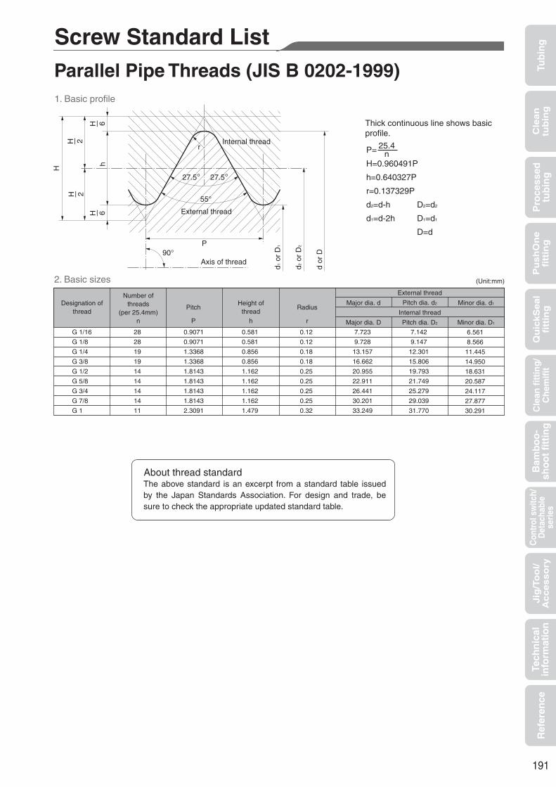
191
Tub
ing
Cle
an
tub
ing
Pu
sh
On
efi
ttin
gQ
uic
kS
ea
lfi
ttin
gB
amb
oo
-sh
oo
t fi
ttin
gC
ontr
ol s
witc
h/D
etac
habl
ese
ries
Cle
an f
itti
ng
/C
hem
ifit
Jig
/To
ol/
Accesso
ryR
efer
ence
Pro
cess
edtu
bin
gTe
chn
ical
info
rmat
ion
Internal threadr
External thread
55°
90°P
27.5° 27.5°
H
h
d1 o
r D
1
d2 o
r D
2
d or
D
P=
H=0.960491P
h=0.640327P
r=0.137329P
d2=d-h
d1=d-2h
D2=d2
D1=d1
D=d
25.4n
Thick continuous line shows basicprofile.
2. Basic sizes (Unit:mm)
Designation ofthread
G 1/16
G 1/8
G 1/4
G 3/8
G 1/2
G 5/8
G 3/4
G 7/8
G 1
0.9071
0.9071
1.3368
1.3368
1.8143
1.8143
1.8143
1.8143
2.3091
0.581
0.581
0.856
0.856
1.162
1.162
1.162
1.162
1.479
0.12
0.12
0.18
0.18
0.25
0.25
0.25
0.25
0.32
7.723
9.728
13.157
16.662
20.955
22.911
26.441
30.201
33.249
7.142
9.147
12.301
15.806
19.793
21.749
25.279
29.039
31.770
6.561
8.566
11.445
14.950
18.631
20.587
24.117
27.877
30.291
28
28
19
19
14
14
14
14
11
PitchHeight of
threadRadius
P h r
Major dia. d Pitch dia. d2
Internal thread
External thread
Minor dia. d1
Major dia. D Pitch dia. D2 Minor dia. D1
Number ofthreads
(per 25.4mm)n
1. Basic profile
Screw Standard ListParallel Pipe Threads (JIS B 0202-1999)
Axis of thread
The above standard is an excerpt from a standard table issued by the Japan Standards Association. For design and trade, be sure to check the appropriate updated standard table.
About thread standard

192
Tub
ing
Cle
an
tub
ing
Pu
sh
On
efi
ttin
gQ
uic
kS
ea
lfi
ttin
gB
amb
oo
-sh
oo
t fi
ttin
gC
ontr
ol s
witc
h/D
etac
habl
ese
ries
Cle
an f
itti
ng
/C
hem
ifit
Jig
/To
ol/
Accesso
ryR
efer
ence
Pro
cess
edtu
bin
gTe
chn
ical
info
rmat
ion
2. Basic size
HH
/2h
h/2
H/2
h/2
55°r
P
90°
16
1
r
D1
D2
DP
r'
r'
55°
90°
h/2
h/2
H'
H'/6
H'/6
h 27.5° 27.5°27.5° 27.5°
Position ofgauge plane
a f
D1 D
2 D
D1 D
2 D
D1 D
2 D
d1d
2d
t
'
Taper external thread
Parallel internal thread
Taper internal thread
Taper internal thread
P=
H=0.960237P
25.4n
Thick continuous line shows basicprofile.
25.4n
Basic profile applied for taper externaland taper internal threads.
Basic profile applied for parallelinternal threads.
Fit between taper external threadand taper internal or parallel internal thread.
h=0.640327P
r=0.137278P
P=
H'=0.960491P
Thick continuous line shows basicprofile.
h=0.640327P
r'=0.137329P
(Unit:mm)
Thread Gauge dia. Position of gauge plane
R1/16R1/8R1/4R3/8R1/2R3/4R1
28281919141411
0.90710.90711.33681.33681.81431.81432.3091
0.5810.5810.8560.8561.1621.1621.479
0.120.120.180.180.250.250.32
7.7239.728
13.15716.66220.95526.44133.249
7.1429.147
12.30115.80619.79325.27931.770
6.5618.566
11.44514.95018.63124.11730.291
3.973.976.016.358.169.53
10.39
±0.91±0.91±1.34±1.34±1.81±1.81±2.31
±1.13±1.13±1.67±1.67±2.27±2.27±2.89
±0.071±0.071±0.104±0.104±0.142±0.142±0.181
2.52.53.73.75.05.06.4
6.26.29.49.7
12.714.116.2
7.47.4
11.011.415.016.319.1
4.44.46.77.09.1
10.211.6
Numberof
threads(per 25.4mm)
n
Pitch
P(referential)
Heightof
thread
h
Radius
r
or
r’
Majordia.d
Pitchdia.d2
Minordia.d1
From pipe end
From endof pipe
orcoupler
(referential)
Fromposition of
gauge planetowardsmallerdia.end
Fromgauge plane
or endof pipe orcoupler
t
Fromposition
ofgaugeplane
towardlargerdia.end
f
Taperinternalthread
Parallelinternalthread
When thereis noincompletethread partTaperinternal thread,parallel internalthread
When there is incomplete thread part
External thread Internal threadLength of useful thread (min.)
Atpipe end
Internal thread
Majordia.D
Pitchdia.D2
Minordia.D1
External threadExternal threadInternalthread Tolerance
onD, D2
andD1
ofparallelinternalthread
Gauge
length
a
Axial
tolerance
b
Axial
tolerance
c '
Designationof
thread
(PT)
1. Basic profile
Taper Pipe Threads (JIS B 0203-1999)
Axis of threadAxis of thread

193
Tub
ing
Cle
an
tub
ing
Pu
sh
On
efi
ttin
gQ
uic
kS
ea
lfi
ttin
gB
amb
oo
-sh
oo
t fi
ttin
gC
ontr
ol s
witc
h/D
etac
habl
ese
ries
Cle
an f
itti
ng
/C
hem
ifit
Jig
/To
ol/
Accesso
ryR
efer
ence
Pro
cess
edtu
bin
gTe
chn
ical
info
rmat
ion
1. Basic profile
2. Basic sizes
Internal thread
External thread
60°
P
30° 30°
H H1
H=0.866025P
H1=0.541266P
d2=d-0.649519P
d1=d-1.082532P
D=d
D2=d2
D1=d1
Primary
0.5
0.6
0.7
0.75
0.8
1
1
1.25
1.25
1.5
1.5
1.75
2
2
2.5
2.5
2.5
3
3
3.5
M7
M9
M11
0.271
0.325
0.379
0.406
0.433
0.541
0.541
0.677
0.677
0.812
0.812
0.947
1.083
1.083
1.353
1.353
1.353
1.624
1.624
1.894
3.000
3.500
4.000
4.500
5.000
6.000
7.000
8.000
9.000
10.000
11.000
12.000
14.000
16.000
18.000
20.000
22.000
24.000
27.000
30.000
2.675
3.110
3.545
4.013
4.480
5.350
6.350
7.188
8.188
9.026
10.026
10.863
12.701
14.701
16.376
18.376
20.376
22.051
25.051
27.727
2.459
2.850
3.242
3.688
4.134
4.917
5.917
6.647
7.647
8.376
9.376
10.106
11.835
13.835
15.294
17.294
19.294
20.752
23.752
26.211
M3.5
M4.5
M14
M18
M22
M27
Tertiary
Pitch
P
Threadoverlap
H1Internal thread
External thread
Secondary
(Unit:mm)
Designation of threadMajor dia. d Pitch dia. d2 Minor dia. d1
Major dia. D Pitch dia. D2 Minor dia. D1
M3
M4
M5
M6
M8
M10
M12
M16
M20
M24
M30
Metric Coarse Screw Threads (JIS B 0205-1987)
90°
Axis of therad
d1 o
r D
1
d2 o
r D
2
d or
D
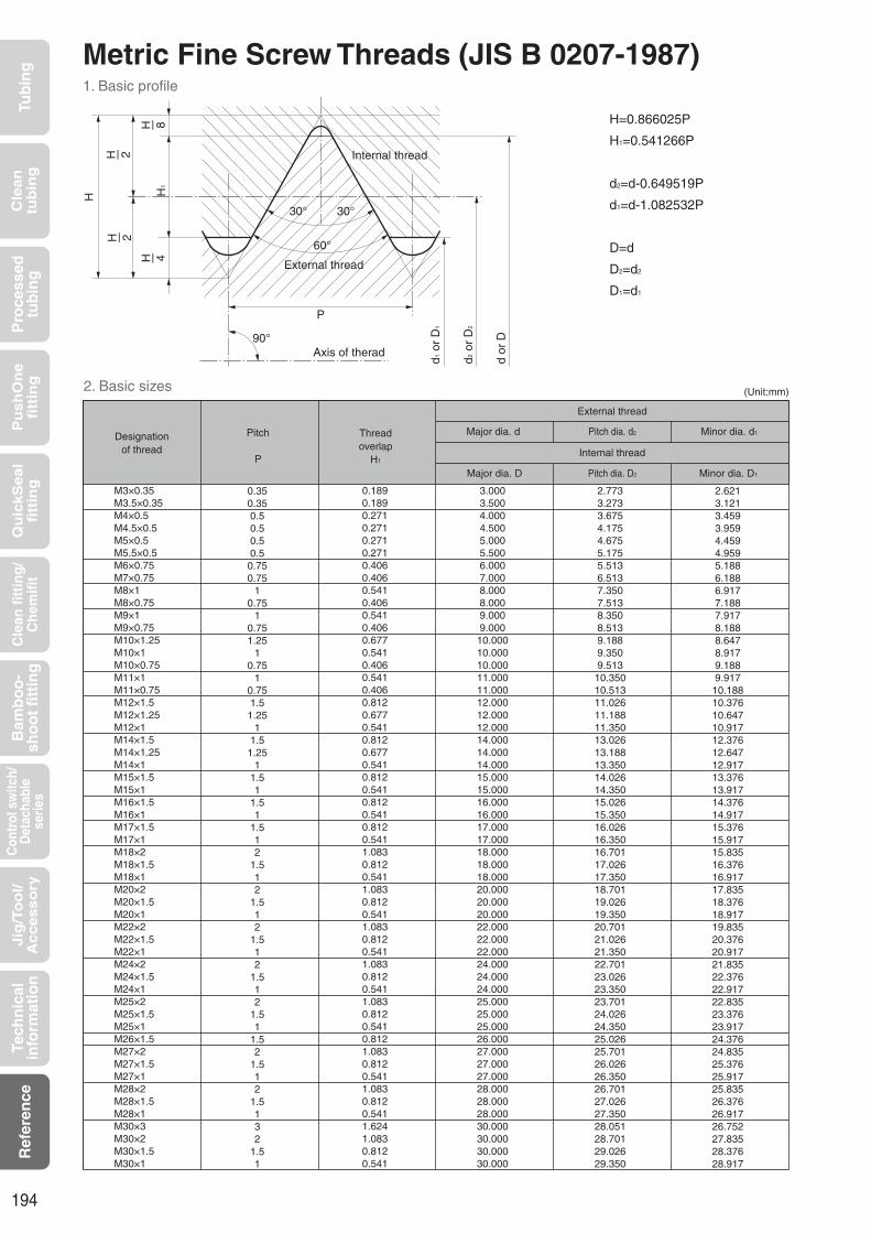
194
Tub
ing
Cle
an
tub
ing
Pu
sh
On
efi
ttin
gQ
uic
kS
ea
lfi
ttin
gB
amb
oo
-sh
oo
t fi
ttin
gC
ontr
ol s
witc
h/D
etac
habl
ese
ries
Cle
an f
itti
ng
/C
hem
ifit
Jig
/To
ol/
Accesso
ryR
efer
ence
Pro
cess
edtu
bin
gTe
chn
ical
info
rmat
ion
Metric Fine Screw Threads (JIS B 0207-1987)1. Basic profile
H=0.866025P
H1=0.541266P
d2=d-0.649519P
d1=d-1.082532P
D=d
D2=d2
D1=d1
2. Basic sizes
Internal thread
External thread
60°
P
30° 30°
H H1
90°Axis of therad
Designationof thread
0.1890.1890.2710.2710.2710.2710.4060.4060.5410.4060.5410.4060.6770.5410.4060.5410.4060.8120.6770.5410.8120.6770.5410.8120.5410.8120.5410.8120.5411.0830.8120.5411.0830.8120.5411.0830.8120.5411.0830.8120.5411.0830.8120.5410.8121.0830.8120.5411.0830.8120.5411.6241.0830.8120.541
3.0003.5004.0004.5005.0005.5006.0007.0008.0008.0009.0009.000
10.00010.00010.00011.00011.00012.00012.00012.00014.00014.00014.00015.00015.00016.00016.00017.00017.00018.00018.00018.00020.00020.00020.00022.00022.00022.00024.00024.00024.00025.00025.00025.00026.00027.00027.00027.00028.00028.00028.00030.00030.00030.00030.000
2.7733.2733.6754.1754.6755.1755.5136.5137.3507.5138.3508.5139.1889.3509.513
10.35010.51311.02611.18811.35013.02613.18813.35014.02614.35015.02615.35016.02616.35016.70117.02617.35018.70119.02619.35020.70121.02621.35022.70123.02623.35023.70124.02624.35025.02625.70126.02626.35026.70127.02627.35028.05128.70129.02629.350
2.6213.1213.4593.9594.4594.9595.1886.1886.9177.1887.9178.1888.6478.9179.1889.917
10.18810.37610.64710.91712.37612.64712.91713.37613.91714.37614.91715.37615.91715.83516.37616.91717.83518.37618.91719.83520.37620.91721.83522.37622.91722.83523.37623.91724.37624.83525.37625.91725.83526.37626.91726.75227.83528.37628.917
0.350.350.50.50.50.50.750.75
10.75
10.751.25
10.75
10.751.51.25
11.51.25
11.51
1.51
1.512
1.512
1.512
1.512
1.512
1.51
1.52
1.512
1.5132
1.51
Threadoverlap
H1
Major dia. d
Major dia. D
Pitch dia. d2
Internal thread
External thread
Pitch dia. D2
Minor dia. d1
Minor dia. D1
Pitch
P
(Unit:mm)
M3×0.35M3.5×0.35M4×0.5M4.5×0.5M5×0.5M5.5×0.5M6×0.75M7×0.75M8×1M8×0.75M9×1M9×0.75M10×1.25M10×1M10×0.75M11×1M11×0.75M12×1.5M12×1.25M12×1M14×1.5M14×1.25M14×1M15×1.5M15×1M16×1.5M16×1M17×1.5M17×1M18×2M18×1.5M18×1M20×2M20×1.5M20×1M22×2M22×1.5M22×1M24×2M24×1.5M24×1M25×2M25×1.5M25×1M26×1.5M27×2M27×1.5M27×1M28×2M28×1.5M28×1M30×3M30×2M30×1.5M30×1
d1 o
r D
1
d2 o
r D
2
d or
D

195
Tub
ing
Cle
an
tub
ing
Pu
sh
On
efi
ttin
gQ
uic
kS
ea
lfi
ttin
gB
amb
oo
-sh
oo
t fi
ttin
gC
ontr
ol s
witc
h/D
etac
habl
ese
ries
Cle
an f
itti
ng
/C
hem
ifit
Jig
/To
ol/
Accesso
ryR
efer
ence
Pro
cess
edtu
bin
gTe
chn
ical
info
rmat
ion
UL (Underwriters Laboratories Inc.) is a non-profit test organization established in 1894 by an American insurance company mainly to respond to the need for improving safety in electric, and later electronic, instruments.Major tasks are various regulations on raw materials, parts, unfinished products and finished products, as well as creation, examination, certification and registration of safety test standards. It has a major influence with a world-wide network.UL-94 standard (Tests for Flammability of Plastic Materials for Parts in Devices and Appliances) is the most fundamental one among several UL standards for plastic materials flammability tests.UL-94 standard has various test methods and flammability classes. Here we introduce self-extinguishing material classes V-0, V-1 and V-2 from the tests for flammability class of materials such as injection-molding grade, extruded plate and press-molded plate.The flammability of general nylon and the material of the polyurethane tubing are tested by UL-94 HB to examine the combustion velocity.
Specimen
Testmethod
Require-ments
94 V-0 94 V-1 94 V-2
Clamp
Specimen
Inner diameter of burner 3/8”
Surgical cotton
2”
1/4”
12”
5”
1/4”
3/8”
3/4”
4”
Conduct a test with no draft.
Prepare a 3/4 inch-high blue burner flame
with no yellow tip.
Apply the adjusted flame to a specimen for 10 seconds
and remove. Observe the specimen burning.
When the burning stops, reapply the flame for an
additional 10 seconds.
A.The specimens may not burn with flaming combustion for more than 10 seconds after either application of the test flame. B.The total flaming combustion time may not exceed 50 seconds for the 10 flame applications for each set of five specimens.C.The specimens may not burn with flaming or glowing combustion up to the holding clamp.D.The specimens may not drip flaming particles that ignite the surgical cotton located 12 inches below the test specimen.E.The specimens may not have glowing com- bustion that persists for more than 30 seconds after the second removal of the test flame.
A.The specimens may not burn with flaming combustion for more than 30 seconds after either application of the test flame. B.The total flaming combustion time may not exceed 250 seconds for the 10 flame applications for each set of five specimens. C.The specimens may not burn with flaming or glowing combustion up to the holding clamp. D.The specimens may not drip flaming particles that ignite the surgical cotton located 12 inches below the test specimen. E.The specimens may not have glowing com- bustion that persists for more than 60 seconds after the second removal of the test flame.
If any one of five specimens does not meet the requirements and if the total flaming combustion time is in the rangebelow (*), test another set of five specimens.The second set has to meet all the requirements. *94V-0 51-55 seconds, 94V-1 251-255 seconds, 94V-2 251-255 seconds
A.The specimens may not burn with flaming combustion for more than 30 seconds after either application of the test flame. B.The total flaming combustion time may not exceed 250 seconds for the 10 flame applications for each set of five specimens. C.The specimens may not burn with flaming or glowing combustion up to the holding clamp. D.The specimens can drip flaming particles that ignite the surgical cotton below the test specimen. E.The specimens may not have glowing com- bustion that persists for more than 60 seconds after the second removal of the test flame.
UL-94 Standard Flame Test
The above is extracted from UL standards as reference.See the appropriate latest original standards for design and trade.
About UL standard
A set of five specimens processed for 48 hours at 23±2 °C and RH50±5%, and a set of five specimens processed for 168 hours at 70±1 °C, each of which is 5 inch (127mm) long, 0.5 inch (12.7mm) wide with the maximum thickness under 0.5 inch.

196
Tub
ing
Cle
an
tub
ing
Pu
sh
On
efi
ttin
gQ
uic
kS
ea
lfi
ttin
gB
amb
oo
-sh
oo
t fi
ttin
gC
ontr
ol s
witc
h/D
etac
habl
ese
ries
Cle
an f
itti
ng
/C
hem
ifit
Jig
/To
ol/
Accesso
ryR
efer
ence
Pro
cess
edtu
bin
gTe
chn
ical
info
rmat
ion
Table of Full Scale of Tubing and ScrewThe size of the tubing and thread can be easily checked by placing the product on the following full-scale figures.
Taper pipe threads
Thread size
Full scale
R1/8 R1/4 R3/8 R1/2
Tubing (outer diameter)
Millimeter size
Inch size
Full scale
φ3
1/8 (φ3.18)
φ3.5 φ4
3/16 (φ4.76)
Full scale
φ6
1/4 (φ6.35)
φ8
5/16 (φ7.94) 3/8 (φ9.53)
Full scale
φ10 φ12
1/2 (φ12.70) 5/8 (φ15.88)
φ16
Metric threads
Thread size
Full scale
M3×0.5 M5×0.8 M6×1.0
Millimeter size
Inch size
Millimeter size
Inch size

197
Tub
ing
Cle
an
tub
ing
Pu
sh
On
efi
ttin
gQ
uic
kS
ea
lfi
ttin
gB
amb
oo
-sh
oo
t fi
ttin
gC
ontr
ol s
witc
h/D
etac
habl
ese
ries
Cle
an f
itti
ng
/C
hem
ifit
Jig
/To
ol/
Accesso
ryR
efer
ence
Pro
cess
edtu
bin
gTe
chn
ical
info
rmat
ion
Unit Conversion TableLength
m
1
2.54×10⁻²
3.048×10⁻¹
9.114×10⁻¹
1.6093×10³
3.937×10
1
1.2×10
3.6×10
6.3360×10⁴
3.2808
8.3333×10⁻²
1
3
5.280×10³
1.0936
2.778×10⁻²
3.3333×10⁻¹
1
1.760×10³
6.2×10⁻⁴
1.6×10⁻⁵
1.9×10⁻⁴
5.7×10⁻⁴
1
inch foot yard mile
Weight
kg
1
1.016×10³
9.072×10²
4.536×10⁻¹
2.835×10⁻²
9.842×10⁻⁴
1
8.9286×10⁻¹
4.464×10⁻⁴
2.79×10⁻⁵
1.1023×10⁻³
1.12
1
5×10⁻⁴
3.13×10⁻⁵
2.2046
2.240×10³
2×10³
1
6.25×10⁻²
3.5274×10
3.5838×10⁴
3.2×10⁴
1.6×10
1
ton(UK) ton(US) lb Ounce
Pressure
Pa
1
1×10⁵
9.8067×10⁴
6.8948×10³
1.3332×10²
MPa
1×10⁻⁶
1×10⁻¹
9.8067×10⁻²
6.8948×10⁻³
1.3332×10⁻⁴
bar
1×10⁻⁵
1
9.8067×10⁻¹
6.4898×10⁻²
1.332×10⁻³
kgf/cm2
1.0197×10⁻⁵
1.0197
1
7.0307×10⁻²
1.3595×10⁻³
psi
1.4504×10⁻⁴
1.4504×10
1.4223×10
1
1.9341×10⁻²
mmHg
7.5006×10⁻³
7.5006×10²
7.3556×10²
5.1715×10
1
Force
N
1
1×10⁻⁵
9.8066
dyn
1×10⁵
1
9.8066×10⁵
kgf
1.0197×10⁻¹
1.0197×10⁻⁶
1
* ņ presents SI units.

198
Tub
ing
Cle
an
tub
ing
Pu
sh
On
efi
ttin
gQ
uic
kS
ea
lfi
ttin
gB
amb
oo
-sh
oo
t fi
ttin
gC
ontr
ol s
witc
h/D
etac
habl
ese
ries
Cle
an f
itti
ng
/C
hem
ifit
Jig
/To
ol/
Accesso
ryR
efer
ence
Pro
cess
edtu
bin
gTe
chn
ical
info
rmat
ion
Chemical(weight concentration %, temperature °C) NBR
2
A
Chemical Resistance Specification Table (for reference) Test is conducted for saturated solutions of chemicals in the table at room temperature unless specifically indicated.
Chemical Resistance Specification Table (alphabetical order)
Tubing material Seal material
Polyurethane Nylon Polyolefin Fluorocarbon resin Brass SUS304 SUS316 PBT PP EPDM FKM
Fitt ing material
[How to read the table]The table shows chemical resistance of materials, not of Nitta’s products (finished products). Therefore the table does
not guarantee the chemical resistance performance of the products.The table is created under certain conditions. The symbol [ ] does not always mean chemical resistance depending
on the environment, condition, and duration of use. Be sure to check under the actual conditions of use.Test is conducted for saturated solutions of chemicals in the table at room temperature unless specifically indicated.The table does not present permeability for gas chemicals. Chemicals that are toxic when permeating, such as
activated gas, cannot be used for Nitta’s products.Contact us for chemical resistance of plated and seal-processed parts.
[Contact us]Before contacting us, check 1. the maximum working pressure, 2. working temperature range, 3. chemical concentration, 4. piping state (environmental state), and 5. use application, and then contact us or our regional office.
[Criteria] : Can be used with no influence, or almost no influence on material : Can be used although having influence to a certain degree on material. Sufficient check is required. : Cannot be used. : No data.
2-Aminophenyl Disulfide
Acetaldehyde
Acetic Acid (10%, 20°C)
Acetic Acid (50%, 20°C)
Acetic Acid (50%, 70°C)
Acetic Acid (100%, 20°C)
Acetic Anhydride
Acetoamide
Acetone
Acetyl Bromide
Acetyl Chloride
Acetylene
Acrylonitrile
Alum
Aluminium Acetate
Aluminium Bromide
Aluminium Chloride
Aluminium Fluoride
Aluminium Nitrate
Aluminium Sulfate
Ammonia Anhydrous
Ammonia Gas Cold
Ammonia Gas Hot
Ammonia Liquid
Ammonia Water
Ammonium Carbonate
Ammonium Chloride
Ammonium Hydroxide
Ammonium Nitrate
Ammonium Persulphate
Ammonium Phosphate
Ammonium Sulfate
Amyl Acetate
Amyl Alcohol
Amyl Borate
Amyl Naphthalene
Anethole
Aniline
Aniline Dyes
Animal Oil (Lard Oil)
Aqua Regia
Arsenic Acid
Asphalt
ASTM Lubricant No.1
ASTM Lubricant No.2
ASTM Lubricant No.3
ASTM Standard Fuel Oil A
ASTM Standard Fuel Oil B
ASTM Standard Fuel Oil C
Balium Hydroxide
Barium Chloride
Barium Sulfate
Barium Sulfide
Beet Sugar Iiquid
Benzoaldehyde
Benzene
Benzine
Benzoic Acid
Benzyl Alcohol
Benzyl Benzoate
Benzyl Chloride
Borax
Boric Acid
Bromine
Bunker Fuel
Butane
Butyl Acetate
Butyl Acrylate
Butyl Alcohol
Butyl Cellosolve
Butyl Stearate
Calcium Acetate
Calcium Arsenate
Calcium Bisulfite
Calcium Chloride
Calcium Hydroxide
Calcium Hypochlorite (20%, 20°C)
Calcium Nitrate
Calcium Sulfide
Cane Sugar Liquor
Carbitol
Carbon Dioxide
Carbon Disulfide
Carbon Oxide
Carbon Tetrachloride
Carbonic Acid
Castor Oil
Cellosolve
Cellosolve Acetate
Chlorine Gas (dry)
Chlorine Gas (wet)
Chloro Acetone
Chloroform
Chlorosulfonic Acid
Chlorotoluene
Chromic Acid (2%, 50°C)
Chromic Acid (2%, 70°C)
Chromic Acid (10%, 70°C)
Chromic Acid (25%, 70°C)
Citric Acid
Coal-Tar
Copper Chloride
Copper Cyanide
Copper Sulfate
Corn Oil
Cotton Seed Oil
Creosote
Cresol
Cyclohexane
Cyclohexanol
Cyclohexanone
Decalin
Developer
Diacetone Alcohol
Dibenzine Ether
Dibutyl Ether
Dibutyl Phthalate
Dichlorobenzene
Diethanol Amine
Diethyl Ether
Diethyl Sebacate
Diisopropyl Ketone
Dimethyl Formamide
Dinitrogen Oxide (Nitrous Oxide)
Dioctyl Phthalate (DOP)
Dioctyl Sebacate (DOS)
Dipentene (Limonene)
Diphenyl
Diphenyl Oxide
Dowtherm(100°C)
Dowtherm(200°C)
Epichlorohydrin
Ester Silicate
Ethanol Amine
Ethyl Acetate
Ethyl Acetoacetate
Ethyl Acrylate
Ethyl Alcohol
Ethyl Benzene
Ethyl Cellulose
Ethyl Chloride
Ethyl Ether (>Diethyl Ether)
Ethyl Oxalate
Ethyl Silicate
Ethylene Chlorohydrin
Ethylene Diamine
Ethylene Dichloride
Ethylene Glycol
Ethylene Oxide
Fatty Acids
Ferric Chloride
Ferric Nitrate
Ferric Sulfate
Fluorine
Fluoroboric Acid
Formaldehyde (40%, 20°C)
Formic Acid (25%, 20°C)
Formic Acid (50%, 20°C)
Formic Acid (90%, 20°C)
Freon 11
Freon 12
Freon 21
Freon 22
Freon 113
Freon 114
Furan
Furfural
Furfuryl Alcohol
Gasoline
Gelatine
Glucose
Glue
Glycerine
Grease
Heavy Water
Heptane
Hexane
Hexyl Alcohol
Hydrazine
Hydrobromic Acid (20%, 20°C)
Hydrobromic Acid (20%, 70°C)
Hydrobromic Acid (37%, 20°C)
Hydrochloric Acid (10%, 20°C)
Hydrochloric Acid (20%, 20°C)
Hydrochloric Acid (20%, 80°C)
Hydrochloric Acid (38%, 20°C)
Hydrocyanic Acid
Hydrofluoric Acid (10%, 20°C)
Hydrofluoric Acid (20%, 20°C)
Hydrofluoric Acid (40%, 20°C)
Hydrofluoric Acid (Anhydrous)
Hydrogen
Hydrogen Peroxide (5%, 20°C)
Hydrogen Peroxide (5%, 50°C)
Hydrogen Peroxide (30%, 20°C)
Hydrogen Sulfide
Hydroquinone
Hypochlorous Acid
Isobutyl Alcohol
Isocyanates
Isooctane
Isopropyl Acetate
Isopropyl Alcohol
Isopropyl Ether
JP Fuel Oil
Kerosene
Ketones
Lacquer
Lactic Acid
Lard Oil
Lead Acetate
Lead Arsenate
Lead Nitrate
Lead Sulfamate
Lead Sulfate
Linoleic Acid
Linseed Oil
Liquid Chlorine
Liquidified Petroleum Gas
Lubricant (Ether Type)
Lubricant (Mineral Oil Type)
Lye Solutions
Magnesium Chloride
Magnesium Hydroxide
Magnesium Sulfate
Maleic Acid
Malic Acid
Mercaptan
Mercuric Chloride
Mercury
Methane
Methyl Acetate
Methyl Alcohol
Methyl Bromide
Methyl Chloride
Methyl Ethyl Ketone
Methyl Isobutyl Ketone
Methyl Metacrylate
Methyl Sulfate
Methylene Dichloride
Mineral Oils
Monochloro Benzene
Monochloro Acetic Acid
Monoethanol Amine
n-Hexa Aldehyde
Naphtha
Naphthalene
Naphthenic Acid
Natural Gas
Nickel Acetate
Nickel Chloride
Nickel Sulfate
Nitric Acid (10%, 20°C)
Nitric Acid (10%, 70°C)
Nitric Acid (30%, 20°C)
Nitric Acid (30%, 70°C)
Nitric Acid (61%, 20°C)
Nitric Acid (fuming, 20°C)
Nitrobenzene
Nitroethane
Nitrogen
Nitromethane
Nitropropane
Octyl Alcohol
Oleic Acid
Olive Oil
Oxalic Acid
Oxygene
Ozone
Palm Oil
Palmitic Acid
Pentane
Perchloric Acid
Perchloroethylene
Petroleum
Phenol
Phenyl Disulfide
Phenyl Hydrazine
Phorone
Phosphoric Acid (50%, 20°C)
Phosphoric Acid (50%, 70°C)
Phosphoric Acid (75%, 20°C)
Phosphorobenzene
Pickling Solution (Nitric Acid 20%/Fluoric Acid 4%)
Pickling Solution (Sulfric Acid 40%/Nitric Acid 15%)
Picric Acid
Pine Oil
Pinene
Piperidine
Potassium Bichromate
Potassium Chloride
Potassium Cyanide
Potassium Hydroxide
Potassium Nitrate
Potassium Permanganate (5%, 20°C)
Potassium Sulfate
Propane
Propyl Acetate
Propyl Alcohol
Propylene
Pyridine
Pyrrole
Salicylic Acid
Salt Water
Sea Water
Silicone Grease
Silicone Oil
Silver Nitrate
Soap Aqueous Solution
Soda Water
Sodium Bicarbonate
Sodium Bisulphate
Sodium Carbonate
Sodium Cyanide
Sodium Hydroxide (10%, 20°C)
Sodium Hydroxide (30%, 20°C)
Sodium Hydroxide (30%, 70°C)
Sodium Hypochlorite (5%, 20°C)
Sodium Hypochlorite (5%, 70°C)
Sodium Metaphosphate
Sodium Nitrate
Sodium Perborate
Sodium Peroxide
Sodium Phosphate
Sodium Silicate
Sodium Sulfate
Sodium Sulfide
Sodium Sulfite
Sodium Thiosulfate
Soy Bean Oil
Stannic Chloride
Stannous Chloride
Stearic Acid
Styrene
Sulfur
Sulfur Chloride
Sulfur Dioxide
Sulfur Trioxide
Sulfuric Acid (10%, 20°C)
Sulfuric Acid (10%, 70°C)
Sulfuric Acid (30%, 20°C)
Sulfuric Acid (30%, 70°C)
Sulfuric Acid (98%, 20°C)
Sulfuric Acid (fuming, 20°C)
Sulfurous Acid
Table Salt
Tannic Acid
Tartaric Acid
Terpineol
Tetrachloroethane
Tetraethyl Lead
Tetrahydro Furan
Tetralin
Tetramethyl Lead
Thionyl Chloride
Toluene
Triacetin
Tributoxyethyl Phosphate
Tributyl Phosphate
Trichloroacetic Acid
Trichloroethylene
Tricresyl Phosphate
Triethanolamine
Tung Oil
Turpentine Oil
Uric Acid
Vegetable Oil
Xylene
Zeolite
Zinc Acetate
Zinc Chloride
Zinc Sulfide

199
Tub
ing
Cle
an
tub
ing
Pu
sh
On
efi
ttin
gQ
uic
kS
ea
lfi
ttin
gB
amb
oo
-sh
oo
t fi
ttin
gC
ontr
ol s
witc
h/D
etac
habl
ese
ries
Cle
an f
itti
ng
/C
hem
ifit
Jig
/To
ol/
Accesso
ryR
efer
ence
Pro
cess
edtu
bin
gTe
chn
ical
info
rmat
ion
B
C
A
Chemical(weight concentration %, temperature °C) NBR
Chemical Resistance Specification Table (for reference) Test is conducted for saturated solutions of chemicals in the table at room temperature unless specifically indicated.
Tubing material Seal material
Polyurethane Nylon Polyolefin Fluorocarbon resin Brass SUS304 SUS316 PBT PP EPDM FKM
Fitt ing material
2-Aminophenyl Disulfide
Acetaldehyde
Acetic Acid (10%, 20°C)
Acetic Acid (50%, 20°C)
Acetic Acid (50%, 70°C)
Acetic Acid (100%, 20°C)
Acetic Anhydride
Acetoamide
Acetone
Acetyl Bromide
Acetyl Chloride
Acetylene
Acrylonitrile
Alum
Aluminium Acetate
Aluminium Bromide
Aluminium Chloride
Aluminium Fluoride
Aluminium Nitrate
Aluminium Sulfate
Ammonia Anhydrous
Ammonia Gas Cold
Ammonia Gas Hot
Ammonia Liquid
Ammonia Water
Ammonium Carbonate
Ammonium Chloride
Ammonium Hydroxide
Ammonium Nitrate
Ammonium Persulphate
Ammonium Phosphate
Ammonium Sulfate
Amyl Acetate
Amyl Alcohol
Amyl Borate
Amyl Naphthalene
Anethole
Aniline
Aniline Dyes
Animal Oil (Lard Oil)
Aqua Regia
Arsenic Acid
Asphalt
ASTM Lubricant No.1
ASTM Lubricant No.2
ASTM Lubricant No.3
ASTM Standard Fuel Oil A
ASTM Standard Fuel Oil B
ASTM Standard Fuel Oil C
Balium Hydroxide
Barium Chloride
Barium Sulfate
Barium Sulfide
Beet Sugar Iiquid
Benzoaldehyde
Benzene
Benzine
Benzoic Acid
Benzyl Alcohol
Benzyl Benzoate
Benzyl Chloride
Borax
Boric Acid
Bromine
Bunker Fuel
Butane
Butyl Acetate
Butyl Acrylate
Butyl Alcohol
Butyl Cellosolve
Butyl Stearate
Calcium Acetate
Calcium Arsenate
Calcium Bisulfite
Calcium Chloride
Calcium Hydroxide
Calcium Hypochlorite (20%, 20°C)
Calcium Nitrate
Calcium Sulfide
Cane Sugar Liquor
Carbitol
Carbon Dioxide
Carbon Disulfide
Carbon Oxide
Carbon Tetrachloride
Carbonic Acid
Castor Oil
Cellosolve
Cellosolve Acetate
Chlorine Gas (dry)
Chlorine Gas (wet)
Chloro Acetone
Chloroform
Chlorosulfonic Acid
Chlorotoluene
Chromic Acid (2%, 50°C)
Chromic Acid (2%, 70°C)
Chromic Acid (10%, 70°C)
Chromic Acid (25%, 70°C)
Citric Acid
Coal-Tar
Copper Chloride
Copper Cyanide
Copper Sulfate
Corn Oil
Cotton Seed Oil
Creosote
Cresol
Cyclohexane
Cyclohexanol
Cyclohexanone
Decalin
Developer
Diacetone Alcohol
Dibenzine Ether
Dibutyl Ether
Dibutyl Phthalate
Dichlorobenzene
Diethanol Amine
Diethyl Ether
Diethyl Sebacate
Diisopropyl Ketone
Dimethyl Formamide
Dinitrogen Oxide (Nitrous Oxide)
Dioctyl Phthalate (DOP)
Dioctyl Sebacate (DOS)
Dipentene (Limonene)
Diphenyl
Diphenyl Oxide
Dowtherm(100°C)
Dowtherm(200°C)
Epichlorohydrin
Ester Silicate
Ethanol Amine
Ethyl Acetate
Ethyl Acetoacetate
Ethyl Acrylate
Ethyl Alcohol
Ethyl Benzene
Ethyl Cellulose
Ethyl Chloride
Ethyl Ether (>Diethyl Ether)
Ethyl Oxalate
Ethyl Silicate
Ethylene Chlorohydrin
Ethylene Diamine
Ethylene Dichloride
Ethylene Glycol
Ethylene Oxide
Fatty Acids
Ferric Chloride
Ferric Nitrate
Ferric Sulfate
Fluorine
Fluoroboric Acid
Formaldehyde (40%, 20°C)
Formic Acid (25%, 20°C)
Formic Acid (50%, 20°C)
Formic Acid (90%, 20°C)
Freon 11
Freon 12
Freon 21
Freon 22
Freon 113
Freon 114
Furan
Furfural
Furfuryl Alcohol
Gasoline
Gelatine
Glucose
Glue
Glycerine
Grease
Heavy Water
Heptane
Hexane
Hexyl Alcohol
Hydrazine
Hydrobromic Acid (20%, 20°C)
Hydrobromic Acid (20%, 70°C)
Hydrobromic Acid (37%, 20°C)
Hydrochloric Acid (10%, 20°C)
Hydrochloric Acid (20%, 20°C)
Hydrochloric Acid (20%, 80°C)
Hydrochloric Acid (38%, 20°C)
Hydrocyanic Acid
Hydrofluoric Acid (10%, 20°C)
Hydrofluoric Acid (20%, 20°C)
Hydrofluoric Acid (40%, 20°C)
Hydrofluoric Acid (Anhydrous)
Hydrogen
Hydrogen Peroxide (5%, 20°C)
Hydrogen Peroxide (5%, 50°C)
Hydrogen Peroxide (30%, 20°C)
Hydrogen Sulfide
Hydroquinone
Hypochlorous Acid
Isobutyl Alcohol
Isocyanates
Isooctane
Isopropyl Acetate
Isopropyl Alcohol
Isopropyl Ether
JP Fuel Oil
Kerosene
Ketones
Lacquer
Lactic Acid
Lard Oil
Lead Acetate
Lead Arsenate
Lead Nitrate
Lead Sulfamate
Lead Sulfate
Linoleic Acid
Linseed Oil
Liquid Chlorine
Liquidified Petroleum Gas
Lubricant (Ether Type)
Lubricant (Mineral Oil Type)
Lye Solutions
Magnesium Chloride
Magnesium Hydroxide
Magnesium Sulfate
Maleic Acid
Malic Acid
Mercaptan
Mercuric Chloride
Mercury
Methane
Methyl Acetate
Methyl Alcohol
Methyl Bromide
Methyl Chloride
Methyl Ethyl Ketone
Methyl Isobutyl Ketone
Methyl Metacrylate
Methyl Sulfate
Methylene Dichloride
Mineral Oils
Monochloro Benzene
Monochloro Acetic Acid
Monoethanol Amine
n-Hexa Aldehyde
Naphtha
Naphthalene
Naphthenic Acid
Natural Gas
Nickel Acetate
Nickel Chloride
Nickel Sulfate
Nitric Acid (10%, 20°C)
Nitric Acid (10%, 70°C)
Nitric Acid (30%, 20°C)
Nitric Acid (30%, 70°C)
Nitric Acid (61%, 20°C)
Nitric Acid (fuming, 20°C)
Nitrobenzene
Nitroethane
Nitrogen
Nitromethane
Nitropropane
Octyl Alcohol
Oleic Acid
Olive Oil
Oxalic Acid
Oxygene
Ozone
Palm Oil
Palmitic Acid
Pentane
Perchloric Acid
Perchloroethylene
Petroleum
Phenol
Phenyl Disulfide
Phenyl Hydrazine
Phorone
Phosphoric Acid (50%, 20°C)
Phosphoric Acid (50%, 70°C)
Phosphoric Acid (75%, 20°C)
Phosphorobenzene
Pickling Solution (Nitric Acid 20%/Fluoric Acid 4%)
Pickling Solution (Sulfric Acid 40%/Nitric Acid 15%)
Picric Acid
Pine Oil
Pinene
Piperidine
Potassium Bichromate
Potassium Chloride
Potassium Cyanide
Potassium Hydroxide
Potassium Nitrate
Potassium Permanganate (5%, 20°C)
Potassium Sulfate
Propane
Propyl Acetate
Propyl Alcohol
Propylene
Pyridine
Pyrrole
Salicylic Acid
Salt Water
Sea Water
Silicone Grease
Silicone Oil
Silver Nitrate
Soap Aqueous Solution
Soda Water
Sodium Bicarbonate
Sodium Bisulphate
Sodium Carbonate
Sodium Cyanide
Sodium Hydroxide (10%, 20°C)
Sodium Hydroxide (30%, 20°C)
Sodium Hydroxide (30%, 70°C)
Sodium Hypochlorite (5%, 20°C)
Sodium Hypochlorite (5%, 70°C)
Sodium Metaphosphate
Sodium Nitrate
Sodium Perborate
Sodium Peroxide
Sodium Phosphate
Sodium Silicate
Sodium Sulfate
Sodium Sulfide
Sodium Sulfite
Sodium Thiosulfate
Soy Bean Oil
Stannic Chloride
Stannous Chloride
Stearic Acid
Styrene
Sulfur
Sulfur Chloride
Sulfur Dioxide
Sulfur Trioxide
Sulfuric Acid (10%, 20°C)
Sulfuric Acid (10%, 70°C)
Sulfuric Acid (30%, 20°C)
Sulfuric Acid (30%, 70°C)
Sulfuric Acid (98%, 20°C)
Sulfuric Acid (fuming, 20°C)
Sulfurous Acid
Table Salt
Tannic Acid
Tartaric Acid
Terpineol
Tetrachloroethane
Tetraethyl Lead
Tetrahydro Furan
Tetralin
Tetramethyl Lead
Thionyl Chloride
Toluene
Triacetin
Tributoxyethyl Phosphate
Tributyl Phosphate
Trichloroacetic Acid
Trichloroethylene
Tricresyl Phosphate
Triethanolamine
Tung Oil
Turpentine Oil
Uric Acid
Vegetable Oil
Xylene
Zeolite
Zinc Acetate
Zinc Chloride
Zinc Sulfide

200
Tub
ing
Cle
an
tub
ing
Pu
sh
On
efi
ttin
gQ
uic
kS
ea
lfi
ttin
gB
amb
oo
-sh
oo
t fi
ttin
gC
ontr
ol s
witc
h/D
etac
habl
ese
ries
Cle
an f
itti
ng
/C
hem
ifit
Jig
/To
ol/
Accesso
ryR
efer
ence
Pro
cess
edtu
bin
gTe
chn
ical
info
rmat
ion
C
D
E
F
Chemical(weight concentration %, temperature °C) NBR
Chemical Resistance Specification Table (for reference) Test is conducted for saturated solutions of chemicals in the table at room temperature unless specifically indicated.
Tubing material Seal material
Polyurethane Nylon Polyolefin Fluorocarbon resin Brass SUS304 SUS316 PBT PP EPDM FKM
Fitt ing material
2-Aminophenyl Disulfide
Acetaldehyde
Acetic Acid (10%, 20°C)
Acetic Acid (50%, 20°C)
Acetic Acid (50%, 70°C)
Acetic Acid (100%, 20°C)
Acetic Anhydride
Acetoamide
Acetone
Acetyl Bromide
Acetyl Chloride
Acetylene
Acrylonitrile
Alum
Aluminium Acetate
Aluminium Bromide
Aluminium Chloride
Aluminium Fluoride
Aluminium Nitrate
Aluminium Sulfate
Ammonia Anhydrous
Ammonia Gas Cold
Ammonia Gas Hot
Ammonia Liquid
Ammonia Water
Ammonium Carbonate
Ammonium Chloride
Ammonium Hydroxide
Ammonium Nitrate
Ammonium Persulphate
Ammonium Phosphate
Ammonium Sulfate
Amyl Acetate
Amyl Alcohol
Amyl Borate
Amyl Naphthalene
Anethole
Aniline
Aniline Dyes
Animal Oil (Lard Oil)
Aqua Regia
Arsenic Acid
Asphalt
ASTM Lubricant No.1
ASTM Lubricant No.2
ASTM Lubricant No.3
ASTM Standard Fuel Oil A
ASTM Standard Fuel Oil B
ASTM Standard Fuel Oil C
Balium Hydroxide
Barium Chloride
Barium Sulfate
Barium Sulfide
Beet Sugar Iiquid
Benzoaldehyde
Benzene
Benzine
Benzoic Acid
Benzyl Alcohol
Benzyl Benzoate
Benzyl Chloride
Borax
Boric Acid
Bromine
Bunker Fuel
Butane
Butyl Acetate
Butyl Acrylate
Butyl Alcohol
Butyl Cellosolve
Butyl Stearate
Calcium Acetate
Calcium Arsenate
Calcium Bisulfite
Calcium Chloride
Calcium Hydroxide
Calcium Hypochlorite (20%, 20°C)
Calcium Nitrate
Calcium Sulfide
Cane Sugar Liquor
Carbitol
Carbon Dioxide
Carbon Disulfide
Carbon Oxide
Carbon Tetrachloride
Carbonic Acid
Castor Oil
Cellosolve
Cellosolve Acetate
Chlorine Gas (dry)
Chlorine Gas (wet)
Chloro Acetone
Chloroform
Chlorosulfonic Acid
Chlorotoluene
Chromic Acid (2%, 50°C)
Chromic Acid (2%, 70°C)
Chromic Acid (10%, 70°C)
Chromic Acid (25%, 70°C)
Citric Acid
Coal-Tar
Copper Chloride
Copper Cyanide
Copper Sulfate
Corn Oil
Cotton Seed Oil
Creosote
Cresol
Cyclohexane
Cyclohexanol
Cyclohexanone
Decalin
Developer
Diacetone Alcohol
Dibenzine Ether
Dibutyl Ether
Dibutyl Phthalate
Dichlorobenzene
Diethanol Amine
Diethyl Ether
Diethyl Sebacate
Diisopropyl Ketone
Dimethyl Formamide
Dinitrogen Oxide (Nitrous Oxide)
Dioctyl Phthalate (DOP)
Dioctyl Sebacate (DOS)
Dipentene (Limonene)
Diphenyl
Diphenyl Oxide
Dowtherm(100°C)
Dowtherm(200°C)
Epichlorohydrin
Ester Silicate
Ethanol Amine
Ethyl Acetate
Ethyl Acetoacetate
Ethyl Acrylate
Ethyl Alcohol
Ethyl Benzene
Ethyl Cellulose
Ethyl Chloride
Ethyl Ether (>Diethyl Ether)
Ethyl Oxalate
Ethyl Silicate
Ethylene Chlorohydrin
Ethylene Diamine
Ethylene Dichloride
Ethylene Glycol
Ethylene Oxide
Fatty Acids
Ferric Chloride
Ferric Nitrate
Ferric Sulfate
Fluorine
Fluoroboric Acid
Formaldehyde (40%, 20°C)
Formic Acid (25%, 20°C)
Formic Acid (50%, 20°C)
Formic Acid (90%, 20°C)
Freon 11
Freon 12
Freon 21
Freon 22
Freon 113
Freon 114
Furan
Furfural
Furfuryl Alcohol
Gasoline
Gelatine
Glucose
Glue
Glycerine
Grease
Heavy Water
Heptane
Hexane
Hexyl Alcohol
Hydrazine
Hydrobromic Acid (20%, 20°C)
Hydrobromic Acid (20%, 70°C)
Hydrobromic Acid (37%, 20°C)
Hydrochloric Acid (10%, 20°C)
Hydrochloric Acid (20%, 20°C)
Hydrochloric Acid (20%, 80°C)
Hydrochloric Acid (38%, 20°C)
Hydrocyanic Acid
Hydrofluoric Acid (10%, 20°C)
Hydrofluoric Acid (20%, 20°C)
Hydrofluoric Acid (40%, 20°C)
Hydrofluoric Acid (Anhydrous)
Hydrogen
Hydrogen Peroxide (5%, 20°C)
Hydrogen Peroxide (5%, 50°C)
Hydrogen Peroxide (30%, 20°C)
Hydrogen Sulfide
Hydroquinone
Hypochlorous Acid
Isobutyl Alcohol
Isocyanates
Isooctane
Isopropyl Acetate
Isopropyl Alcohol
Isopropyl Ether
JP Fuel Oil
Kerosene
Ketones
Lacquer
Lactic Acid
Lard Oil
Lead Acetate
Lead Arsenate
Lead Nitrate
Lead Sulfamate
Lead Sulfate
Linoleic Acid
Linseed Oil
Liquid Chlorine
Liquidified Petroleum Gas
Lubricant (Ether Type)
Lubricant (Mineral Oil Type)
Lye Solutions
Magnesium Chloride
Magnesium Hydroxide
Magnesium Sulfate
Maleic Acid
Malic Acid
Mercaptan
Mercuric Chloride
Mercury
Methane
Methyl Acetate
Methyl Alcohol
Methyl Bromide
Methyl Chloride
Methyl Ethyl Ketone
Methyl Isobutyl Ketone
Methyl Metacrylate
Methyl Sulfate
Methylene Dichloride
Mineral Oils
Monochloro Benzene
Monochloro Acetic Acid
Monoethanol Amine
n-Hexa Aldehyde
Naphtha
Naphthalene
Naphthenic Acid
Natural Gas
Nickel Acetate
Nickel Chloride
Nickel Sulfate
Nitric Acid (10%, 20°C)
Nitric Acid (10%, 70°C)
Nitric Acid (30%, 20°C)
Nitric Acid (30%, 70°C)
Nitric Acid (61%, 20°C)
Nitric Acid (fuming, 20°C)
Nitrobenzene
Nitroethane
Nitrogen
Nitromethane
Nitropropane
Octyl Alcohol
Oleic Acid
Olive Oil
Oxalic Acid
Oxygene
Ozone
Palm Oil
Palmitic Acid
Pentane
Perchloric Acid
Perchloroethylene
Petroleum
Phenol
Phenyl Disulfide
Phenyl Hydrazine
Phorone
Phosphoric Acid (50%, 20°C)
Phosphoric Acid (50%, 70°C)
Phosphoric Acid (75%, 20°C)
Phosphorobenzene
Pickling Solution (Nitric Acid 20%/Fluoric Acid 4%)
Pickling Solution (Sulfric Acid 40%/Nitric Acid 15%)
Picric Acid
Pine Oil
Pinene
Piperidine
Potassium Bichromate
Potassium Chloride
Potassium Cyanide
Potassium Hydroxide
Potassium Nitrate
Potassium Permanganate (5%, 20°C)
Potassium Sulfate
Propane
Propyl Acetate
Propyl Alcohol
Propylene
Pyridine
Pyrrole
Salicylic Acid
Salt Water
Sea Water
Silicone Grease
Silicone Oil
Silver Nitrate
Soap Aqueous Solution
Soda Water
Sodium Bicarbonate
Sodium Bisulphate
Sodium Carbonate
Sodium Cyanide
Sodium Hydroxide (10%, 20°C)
Sodium Hydroxide (30%, 20°C)
Sodium Hydroxide (30%, 70°C)
Sodium Hypochlorite (5%, 20°C)
Sodium Hypochlorite (5%, 70°C)
Sodium Metaphosphate
Sodium Nitrate
Sodium Perborate
Sodium Peroxide
Sodium Phosphate
Sodium Silicate
Sodium Sulfate
Sodium Sulfide
Sodium Sulfite
Sodium Thiosulfate
Soy Bean Oil
Stannic Chloride
Stannous Chloride
Stearic Acid
Styrene
Sulfur
Sulfur Chloride
Sulfur Dioxide
Sulfur Trioxide
Sulfuric Acid (10%, 20°C)
Sulfuric Acid (10%, 70°C)
Sulfuric Acid (30%, 20°C)
Sulfuric Acid (30%, 70°C)
Sulfuric Acid (98%, 20°C)
Sulfuric Acid (fuming, 20°C)
Sulfurous Acid
Table Salt
Tannic Acid
Tartaric Acid
Terpineol
Tetrachloroethane
Tetraethyl Lead
Tetrahydro Furan
Tetralin
Tetramethyl Lead
Thionyl Chloride
Toluene
Triacetin
Tributoxyethyl Phosphate
Tributyl Phosphate
Trichloroacetic Acid
Trichloroethylene
Tricresyl Phosphate
Triethanolamine
Tung Oil
Turpentine Oil
Uric Acid
Vegetable Oil
Xylene
Zeolite
Zinc Acetate
Zinc Chloride
Zinc Sulfide

201
Tub
ing
Cle
an
tub
ing
Pu
sh
On
efi
ttin
gQ
uic
kS
ea
lfi
ttin
gB
amb
oo
-sh
oo
t fi
ttin
gC
ontr
ol s
witc
h/D
etac
habl
ese
ries
Cle
an f
itti
ng
/C
hem
ifit
Jig
/To
ol/
Accesso
ryR
efer
ence
Pro
cess
edtu
bin
gTe
chn
ical
info
rmat
ion
F
G
H
I
J
K
L
Chemical(weight concentration %, temperature °C) NBR
Chemical Resistance Specification Table (for reference) Test is conducted for saturated solutions of chemicals in the table at room temperature unless specifically indicated.
Tubing material Seal material
Polyurethane Nylon Polyolefin Fluorocarbon resin Brass SUS304 SUS316 PBT PP EPDM FKM
Fitt ing material
2-Aminophenyl Disulfide
Acetaldehyde
Acetic Acid (10%, 20°C)
Acetic Acid (50%, 20°C)
Acetic Acid (50%, 70°C)
Acetic Acid (100%, 20°C)
Acetic Anhydride
Acetoamide
Acetone
Acetyl Bromide
Acetyl Chloride
Acetylene
Acrylonitrile
Alum
Aluminium Acetate
Aluminium Bromide
Aluminium Chloride
Aluminium Fluoride
Aluminium Nitrate
Aluminium Sulfate
Ammonia Anhydrous
Ammonia Gas Cold
Ammonia Gas Hot
Ammonia Liquid
Ammonia Water
Ammonium Carbonate
Ammonium Chloride
Ammonium Hydroxide
Ammonium Nitrate
Ammonium Persulphate
Ammonium Phosphate
Ammonium Sulfate
Amyl Acetate
Amyl Alcohol
Amyl Borate
Amyl Naphthalene
Anethole
Aniline
Aniline Dyes
Animal Oil (Lard Oil)
Aqua Regia
Arsenic Acid
Asphalt
ASTM Lubricant No.1
ASTM Lubricant No.2
ASTM Lubricant No.3
ASTM Standard Fuel Oil A
ASTM Standard Fuel Oil B
ASTM Standard Fuel Oil C
Balium Hydroxide
Barium Chloride
Barium Sulfate
Barium Sulfide
Beet Sugar Iiquid
Benzoaldehyde
Benzene
Benzine
Benzoic Acid
Benzyl Alcohol
Benzyl Benzoate
Benzyl Chloride
Borax
Boric Acid
Bromine
Bunker Fuel
Butane
Butyl Acetate
Butyl Acrylate
Butyl Alcohol
Butyl Cellosolve
Butyl Stearate
Calcium Acetate
Calcium Arsenate
Calcium Bisulfite
Calcium Chloride
Calcium Hydroxide
Calcium Hypochlorite (20%, 20°C)
Calcium Nitrate
Calcium Sulfide
Cane Sugar Liquor
Carbitol
Carbon Dioxide
Carbon Disulfide
Carbon Oxide
Carbon Tetrachloride
Carbonic Acid
Castor Oil
Cellosolve
Cellosolve Acetate
Chlorine Gas (dry)
Chlorine Gas (wet)
Chloro Acetone
Chloroform
Chlorosulfonic Acid
Chlorotoluene
Chromic Acid (2%, 50°C)
Chromic Acid (2%, 70°C)
Chromic Acid (10%, 70°C)
Chromic Acid (25%, 70°C)
Citric Acid
Coal-Tar
Copper Chloride
Copper Cyanide
Copper Sulfate
Corn Oil
Cotton Seed Oil
Creosote
Cresol
Cyclohexane
Cyclohexanol
Cyclohexanone
Decalin
Developer
Diacetone Alcohol
Dibenzine Ether
Dibutyl Ether
Dibutyl Phthalate
Dichlorobenzene
Diethanol Amine
Diethyl Ether
Diethyl Sebacate
Diisopropyl Ketone
Dimethyl Formamide
Dinitrogen Oxide (Nitrous Oxide)
Dioctyl Phthalate (DOP)
Dioctyl Sebacate (DOS)
Dipentene (Limonene)
Diphenyl
Diphenyl Oxide
Dowtherm(100°C)
Dowtherm(200°C)
Epichlorohydrin
Ester Silicate
Ethanol Amine
Ethyl Acetate
Ethyl Acetoacetate
Ethyl Acrylate
Ethyl Alcohol
Ethyl Benzene
Ethyl Cellulose
Ethyl Chloride
Ethyl Ether (>Diethyl Ether)
Ethyl Oxalate
Ethyl Silicate
Ethylene Chlorohydrin
Ethylene Diamine
Ethylene Dichloride
Ethylene Glycol
Ethylene Oxide
Fatty Acids
Ferric Chloride
Ferric Nitrate
Ferric Sulfate
Fluorine
Fluoroboric Acid
Formaldehyde (40%, 20°C)
Formic Acid (25%, 20°C)
Formic Acid (50%, 20°C)
Formic Acid (90%, 20°C)
Freon 11
Freon 12
Freon 21
Freon 22
Freon 113
Freon 114
Furan
Furfural
Furfuryl Alcohol
Gasoline
Gelatine
Glucose
Glue
Glycerine
Grease
Heavy Water
Heptane
Hexane
Hexyl Alcohol
Hydrazine
Hydrobromic Acid (20%, 20°C)
Hydrobromic Acid (20%, 70°C)
Hydrobromic Acid (37%, 20°C)
Hydrochloric Acid (10%, 20°C)
Hydrochloric Acid (20%, 20°C)
Hydrochloric Acid (20%, 80°C)
Hydrochloric Acid (38%, 20°C)
Hydrocyanic Acid
Hydrofluoric Acid (10%, 20°C)
Hydrofluoric Acid (20%, 20°C)
Hydrofluoric Acid (40%, 20°C)
Hydrofluoric Acid (Anhydrous)
Hydrogen
Hydrogen Peroxide (5%, 20°C)
Hydrogen Peroxide (5%, 50°C)
Hydrogen Peroxide (30%, 20°C)
Hydrogen Sulfide
Hydroquinone
Hypochlorous Acid
Isobutyl Alcohol
Isocyanates
Isooctane
Isopropyl Acetate
Isopropyl Alcohol
Isopropyl Ether
JP Fuel Oil
Kerosene
Ketones
Lacquer
Lactic Acid
Lard Oil
Lead Acetate
Lead Arsenate
Lead Nitrate
Lead Sulfamate
Lead Sulfate
Linoleic Acid
Linseed Oil
Liquid Chlorine
Liquidified Petroleum Gas
Lubricant (Ether Type)
Lubricant (Mineral Oil Type)
Lye Solutions
Magnesium Chloride
Magnesium Hydroxide
Magnesium Sulfate
Maleic Acid
Malic Acid
Mercaptan
Mercuric Chloride
Mercury
Methane
Methyl Acetate
Methyl Alcohol
Methyl Bromide
Methyl Chloride
Methyl Ethyl Ketone
Methyl Isobutyl Ketone
Methyl Metacrylate
Methyl Sulfate
Methylene Dichloride
Mineral Oils
Monochloro Benzene
Monochloro Acetic Acid
Monoethanol Amine
n-Hexa Aldehyde
Naphtha
Naphthalene
Naphthenic Acid
Natural Gas
Nickel Acetate
Nickel Chloride
Nickel Sulfate
Nitric Acid (10%, 20°C)
Nitric Acid (10%, 70°C)
Nitric Acid (30%, 20°C)
Nitric Acid (30%, 70°C)
Nitric Acid (61%, 20°C)
Nitric Acid (fuming, 20°C)
Nitrobenzene
Nitroethane
Nitrogen
Nitromethane
Nitropropane
Octyl Alcohol
Oleic Acid
Olive Oil
Oxalic Acid
Oxygene
Ozone
Palm Oil
Palmitic Acid
Pentane
Perchloric Acid
Perchloroethylene
Petroleum
Phenol
Phenyl Disulfide
Phenyl Hydrazine
Phorone
Phosphoric Acid (50%, 20°C)
Phosphoric Acid (50%, 70°C)
Phosphoric Acid (75%, 20°C)
Phosphorobenzene
Pickling Solution (Nitric Acid 20%/Fluoric Acid 4%)
Pickling Solution (Sulfric Acid 40%/Nitric Acid 15%)
Picric Acid
Pine Oil
Pinene
Piperidine
Potassium Bichromate
Potassium Chloride
Potassium Cyanide
Potassium Hydroxide
Potassium Nitrate
Potassium Permanganate (5%, 20°C)
Potassium Sulfate
Propane
Propyl Acetate
Propyl Alcohol
Propylene
Pyridine
Pyrrole
Salicylic Acid
Salt Water
Sea Water
Silicone Grease
Silicone Oil
Silver Nitrate
Soap Aqueous Solution
Soda Water
Sodium Bicarbonate
Sodium Bisulphate
Sodium Carbonate
Sodium Cyanide
Sodium Hydroxide (10%, 20°C)
Sodium Hydroxide (30%, 20°C)
Sodium Hydroxide (30%, 70°C)
Sodium Hypochlorite (5%, 20°C)
Sodium Hypochlorite (5%, 70°C)
Sodium Metaphosphate
Sodium Nitrate
Sodium Perborate
Sodium Peroxide
Sodium Phosphate
Sodium Silicate
Sodium Sulfate
Sodium Sulfide
Sodium Sulfite
Sodium Thiosulfate
Soy Bean Oil
Stannic Chloride
Stannous Chloride
Stearic Acid
Styrene
Sulfur
Sulfur Chloride
Sulfur Dioxide
Sulfur Trioxide
Sulfuric Acid (10%, 20°C)
Sulfuric Acid (10%, 70°C)
Sulfuric Acid (30%, 20°C)
Sulfuric Acid (30%, 70°C)
Sulfuric Acid (98%, 20°C)
Sulfuric Acid (fuming, 20°C)
Sulfurous Acid
Table Salt
Tannic Acid
Tartaric Acid
Terpineol
Tetrachloroethane
Tetraethyl Lead
Tetrahydro Furan
Tetralin
Tetramethyl Lead
Thionyl Chloride
Toluene
Triacetin
Tributoxyethyl Phosphate
Tributyl Phosphate
Trichloroacetic Acid
Trichloroethylene
Tricresyl Phosphate
Triethanolamine
Tung Oil
Turpentine Oil
Uric Acid
Vegetable Oil
Xylene
Zeolite
Zinc Acetate
Zinc Chloride
Zinc Sulfide

202
Tub
ing
Cle
an
tub
ing
Pu
sh
On
efi
ttin
gQ
uic
kS
ea
lfi
ttin
gB
amb
oo
-sh
oo
t fi
ttin
gC
ontr
ol s
witc
h/D
etac
habl
ese
ries
Cle
an f
itti
ng
/C
hem
ifit
Jig
/To
ol/
Accesso
ryR
efer
ence
Pro
cess
edtu
bin
gTe
chn
ical
info
rmat
ion
L
M
N
O
P
Chemical(weight concentration %, temperature °C) NBR
Chemical Resistance Specification Table (for reference) Test is conducted for saturated solutions of chemicals in the table at room temperature unless specifically indicated.
Tubing material Seal material
Polyurethane Nylon Polyolefin Fluorocarbon resin Brass SUS304 SUS316 PBT PP EPDM FKM
Fitt ing material
2-Aminophenyl Disulfide
Acetaldehyde
Acetic Acid (10%, 20°C)
Acetic Acid (50%, 20°C)
Acetic Acid (50%, 70°C)
Acetic Acid (100%, 20°C)
Acetic Anhydride
Acetoamide
Acetone
Acetyl Bromide
Acetyl Chloride
Acetylene
Acrylonitrile
Alum
Aluminium Acetate
Aluminium Bromide
Aluminium Chloride
Aluminium Fluoride
Aluminium Nitrate
Aluminium Sulfate
Ammonia Anhydrous
Ammonia Gas Cold
Ammonia Gas Hot
Ammonia Liquid
Ammonia Water
Ammonium Carbonate
Ammonium Chloride
Ammonium Hydroxide
Ammonium Nitrate
Ammonium Persulphate
Ammonium Phosphate
Ammonium Sulfate
Amyl Acetate
Amyl Alcohol
Amyl Borate
Amyl Naphthalene
Anethole
Aniline
Aniline Dyes
Animal Oil (Lard Oil)
Aqua Regia
Arsenic Acid
Asphalt
ASTM Lubricant No.1
ASTM Lubricant No.2
ASTM Lubricant No.3
ASTM Standard Fuel Oil A
ASTM Standard Fuel Oil B
ASTM Standard Fuel Oil C
Balium Hydroxide
Barium Chloride
Barium Sulfate
Barium Sulfide
Beet Sugar Iiquid
Benzoaldehyde
Benzene
Benzine
Benzoic Acid
Benzyl Alcohol
Benzyl Benzoate
Benzyl Chloride
Borax
Boric Acid
Bromine
Bunker Fuel
Butane
Butyl Acetate
Butyl Acrylate
Butyl Alcohol
Butyl Cellosolve
Butyl Stearate
Calcium Acetate
Calcium Arsenate
Calcium Bisulfite
Calcium Chloride
Calcium Hydroxide
Calcium Hypochlorite (20%, 20°C)
Calcium Nitrate
Calcium Sulfide
Cane Sugar Liquor
Carbitol
Carbon Dioxide
Carbon Disulfide
Carbon Oxide
Carbon Tetrachloride
Carbonic Acid
Castor Oil
Cellosolve
Cellosolve Acetate
Chlorine Gas (dry)
Chlorine Gas (wet)
Chloro Acetone
Chloroform
Chlorosulfonic Acid
Chlorotoluene
Chromic Acid (2%, 50°C)
Chromic Acid (2%, 70°C)
Chromic Acid (10%, 70°C)
Chromic Acid (25%, 70°C)
Citric Acid
Coal-Tar
Copper Chloride
Copper Cyanide
Copper Sulfate
Corn Oil
Cotton Seed Oil
Creosote
Cresol
Cyclohexane
Cyclohexanol
Cyclohexanone
Decalin
Developer
Diacetone Alcohol
Dibenzine Ether
Dibutyl Ether
Dibutyl Phthalate
Dichlorobenzene
Diethanol Amine
Diethyl Ether
Diethyl Sebacate
Diisopropyl Ketone
Dimethyl Formamide
Dinitrogen Oxide (Nitrous Oxide)
Dioctyl Phthalate (DOP)
Dioctyl Sebacate (DOS)
Dipentene (Limonene)
Diphenyl
Diphenyl Oxide
Dowtherm(100°C)
Dowtherm(200°C)
Epichlorohydrin
Ester Silicate
Ethanol Amine
Ethyl Acetate
Ethyl Acetoacetate
Ethyl Acrylate
Ethyl Alcohol
Ethyl Benzene
Ethyl Cellulose
Ethyl Chloride
Ethyl Ether (>Diethyl Ether)
Ethyl Oxalate
Ethyl Silicate
Ethylene Chlorohydrin
Ethylene Diamine
Ethylene Dichloride
Ethylene Glycol
Ethylene Oxide
Fatty Acids
Ferric Chloride
Ferric Nitrate
Ferric Sulfate
Fluorine
Fluoroboric Acid
Formaldehyde (40%, 20°C)
Formic Acid (25%, 20°C)
Formic Acid (50%, 20°C)
Formic Acid (90%, 20°C)
Freon 11
Freon 12
Freon 21
Freon 22
Freon 113
Freon 114
Furan
Furfural
Furfuryl Alcohol
Gasoline
Gelatine
Glucose
Glue
Glycerine
Grease
Heavy Water
Heptane
Hexane
Hexyl Alcohol
Hydrazine
Hydrobromic Acid (20%, 20°C)
Hydrobromic Acid (20%, 70°C)
Hydrobromic Acid (37%, 20°C)
Hydrochloric Acid (10%, 20°C)
Hydrochloric Acid (20%, 20°C)
Hydrochloric Acid (20%, 80°C)
Hydrochloric Acid (38%, 20°C)
Hydrocyanic Acid
Hydrofluoric Acid (10%, 20°C)
Hydrofluoric Acid (20%, 20°C)
Hydrofluoric Acid (40%, 20°C)
Hydrofluoric Acid (Anhydrous)
Hydrogen
Hydrogen Peroxide (5%, 20°C)
Hydrogen Peroxide (5%, 50°C)
Hydrogen Peroxide (30%, 20°C)
Hydrogen Sulfide
Hydroquinone
Hypochlorous Acid
Isobutyl Alcohol
Isocyanates
Isooctane
Isopropyl Acetate
Isopropyl Alcohol
Isopropyl Ether
JP Fuel Oil
Kerosene
Ketones
Lacquer
Lactic Acid
Lard Oil
Lead Acetate
Lead Arsenate
Lead Nitrate
Lead Sulfamate
Lead Sulfate
Linoleic Acid
Linseed Oil
Liquid Chlorine
Liquidified Petroleum Gas
Lubricant (Ether Type)
Lubricant (Mineral Oil Type)
Lye Solutions
Magnesium Chloride
Magnesium Hydroxide
Magnesium Sulfate
Maleic Acid
Malic Acid
Mercaptan
Mercuric Chloride
Mercury
Methane
Methyl Acetate
Methyl Alcohol
Methyl Bromide
Methyl Chloride
Methyl Ethyl Ketone
Methyl Isobutyl Ketone
Methyl Metacrylate
Methyl Sulfate
Methylene Dichloride
Mineral Oils
Monochloro Benzene
Monochloro Acetic Acid
Monoethanol Amine
n-Hexa Aldehyde
Naphtha
Naphthalene
Naphthenic Acid
Natural Gas
Nickel Acetate
Nickel Chloride
Nickel Sulfate
Nitric Acid (10%, 20°C)
Nitric Acid (10%, 70°C)
Nitric Acid (30%, 20°C)
Nitric Acid (30%, 70°C)
Nitric Acid (61%, 20°C)
Nitric Acid (fuming, 20°C)
Nitrobenzene
Nitroethane
Nitrogen
Nitromethane
Nitropropane
Octyl Alcohol
Oleic Acid
Olive Oil
Oxalic Acid
Oxygene
Ozone
Palm Oil
Palmitic Acid
Pentane
Perchloric Acid
Perchloroethylene
Petroleum
Phenol
Phenyl Disulfide
Phenyl Hydrazine
Phorone
Phosphoric Acid (50%, 20°C)
Phosphoric Acid (50%, 70°C)
Phosphoric Acid (75%, 20°C)
Phosphorobenzene
Pickling Solution (Nitric Acid 20%/Fluoric Acid 4%)
Pickling Solution (Sulfric Acid 40%/Nitric Acid 15%)
Picric Acid
Pine Oil
Pinene
Piperidine
Potassium Bichromate
Potassium Chloride
Potassium Cyanide
Potassium Hydroxide
Potassium Nitrate
Potassium Permanganate (5%, 20°C)
Potassium Sulfate
Propane
Propyl Acetate
Propyl Alcohol
Propylene
Pyridine
Pyrrole
Salicylic Acid
Salt Water
Sea Water
Silicone Grease
Silicone Oil
Silver Nitrate
Soap Aqueous Solution
Soda Water
Sodium Bicarbonate
Sodium Bisulphate
Sodium Carbonate
Sodium Cyanide
Sodium Hydroxide (10%, 20°C)
Sodium Hydroxide (30%, 20°C)
Sodium Hydroxide (30%, 70°C)
Sodium Hypochlorite (5%, 20°C)
Sodium Hypochlorite (5%, 70°C)
Sodium Metaphosphate
Sodium Nitrate
Sodium Perborate
Sodium Peroxide
Sodium Phosphate
Sodium Silicate
Sodium Sulfate
Sodium Sulfide
Sodium Sulfite
Sodium Thiosulfate
Soy Bean Oil
Stannic Chloride
Stannous Chloride
Stearic Acid
Styrene
Sulfur
Sulfur Chloride
Sulfur Dioxide
Sulfur Trioxide
Sulfuric Acid (10%, 20°C)
Sulfuric Acid (10%, 70°C)
Sulfuric Acid (30%, 20°C)
Sulfuric Acid (30%, 70°C)
Sulfuric Acid (98%, 20°C)
Sulfuric Acid (fuming, 20°C)
Sulfurous Acid
Table Salt
Tannic Acid
Tartaric Acid
Terpineol
Tetrachloroethane
Tetraethyl Lead
Tetrahydro Furan
Tetralin
Tetramethyl Lead
Thionyl Chloride
Toluene
Triacetin
Tributoxyethyl Phosphate
Tributyl Phosphate
Trichloroacetic Acid
Trichloroethylene
Tricresyl Phosphate
Triethanolamine
Tung Oil
Turpentine Oil
Uric Acid
Vegetable Oil
Xylene
Zeolite
Zinc Acetate
Zinc Chloride
Zinc Sulfide

203
Tub
ing
Cle
an
tub
ing
Pu
sh
On
efi
ttin
gQ
uic
kS
ea
lfi
ttin
gB
amb
oo
-sh
oo
t fi
ttin
gC
ontr
ol s
witc
h/D
etac
habl
ese
ries
Cle
an f
itti
ng
/C
hem
ifit
Jig
/To
ol/
Accesso
ryR
efer
ence
Pro
cess
edtu
bin
gTe
chn
ical
info
rmat
ion
P
S
Chemical(weight concentration %, temperature °C) NBR
Chemical Resistance Specification Table (for reference) Test is conducted for saturated solutions of chemicals in the table at room temperature unless specifically indicated.
Tubing material Seal material
Polyurethane Nylon Polyolefin Fluorocarbon resin Brass SUS304 SUS316 PBT PP EPDM FKM
Fitt ing material
2-Aminophenyl Disulfide
Acetaldehyde
Acetic Acid (10%, 20°C)
Acetic Acid (50%, 20°C)
Acetic Acid (50%, 70°C)
Acetic Acid (100%, 20°C)
Acetic Anhydride
Acetoamide
Acetone
Acetyl Bromide
Acetyl Chloride
Acetylene
Acrylonitrile
Alum
Aluminium Acetate
Aluminium Bromide
Aluminium Chloride
Aluminium Fluoride
Aluminium Nitrate
Aluminium Sulfate
Ammonia Anhydrous
Ammonia Gas Cold
Ammonia Gas Hot
Ammonia Liquid
Ammonia Water
Ammonium Carbonate
Ammonium Chloride
Ammonium Hydroxide
Ammonium Nitrate
Ammonium Persulphate
Ammonium Phosphate
Ammonium Sulfate
Amyl Acetate
Amyl Alcohol
Amyl Borate
Amyl Naphthalene
Anethole
Aniline
Aniline Dyes
Animal Oil (Lard Oil)
Aqua Regia
Arsenic Acid
Asphalt
ASTM Lubricant No.1
ASTM Lubricant No.2
ASTM Lubricant No.3
ASTM Standard Fuel Oil A
ASTM Standard Fuel Oil B
ASTM Standard Fuel Oil C
Balium Hydroxide
Barium Chloride
Barium Sulfate
Barium Sulfide
Beet Sugar Iiquid
Benzoaldehyde
Benzene
Benzine
Benzoic Acid
Benzyl Alcohol
Benzyl Benzoate
Benzyl Chloride
Borax
Boric Acid
Bromine
Bunker Fuel
Butane
Butyl Acetate
Butyl Acrylate
Butyl Alcohol
Butyl Cellosolve
Butyl Stearate
Calcium Acetate
Calcium Arsenate
Calcium Bisulfite
Calcium Chloride
Calcium Hydroxide
Calcium Hypochlorite (20%, 20°C)
Calcium Nitrate
Calcium Sulfide
Cane Sugar Liquor
Carbitol
Carbon Dioxide
Carbon Disulfide
Carbon Oxide
Carbon Tetrachloride
Carbonic Acid
Castor Oil
Cellosolve
Cellosolve Acetate
Chlorine Gas (dry)
Chlorine Gas (wet)
Chloro Acetone
Chloroform
Chlorosulfonic Acid
Chlorotoluene
Chromic Acid (2%, 50°C)
Chromic Acid (2%, 70°C)
Chromic Acid (10%, 70°C)
Chromic Acid (25%, 70°C)
Citric Acid
Coal-Tar
Copper Chloride
Copper Cyanide
Copper Sulfate
Corn Oil
Cotton Seed Oil
Creosote
Cresol
Cyclohexane
Cyclohexanol
Cyclohexanone
Decalin
Developer
Diacetone Alcohol
Dibenzine Ether
Dibutyl Ether
Dibutyl Phthalate
Dichlorobenzene
Diethanol Amine
Diethyl Ether
Diethyl Sebacate
Diisopropyl Ketone
Dimethyl Formamide
Dinitrogen Oxide (Nitrous Oxide)
Dioctyl Phthalate (DOP)
Dioctyl Sebacate (DOS)
Dipentene (Limonene)
Diphenyl
Diphenyl Oxide
Dowtherm(100°C)
Dowtherm(200°C)
Epichlorohydrin
Ester Silicate
Ethanol Amine
Ethyl Acetate
Ethyl Acetoacetate
Ethyl Acrylate
Ethyl Alcohol
Ethyl Benzene
Ethyl Cellulose
Ethyl Chloride
Ethyl Ether (>Diethyl Ether)
Ethyl Oxalate
Ethyl Silicate
Ethylene Chlorohydrin
Ethylene Diamine
Ethylene Dichloride
Ethylene Glycol
Ethylene Oxide
Fatty Acids
Ferric Chloride
Ferric Nitrate
Ferric Sulfate
Fluorine
Fluoroboric Acid
Formaldehyde (40%, 20°C)
Formic Acid (25%, 20°C)
Formic Acid (50%, 20°C)
Formic Acid (90%, 20°C)
Freon 11
Freon 12
Freon 21
Freon 22
Freon 113
Freon 114
Furan
Furfural
Furfuryl Alcohol
Gasoline
Gelatine
Glucose
Glue
Glycerine
Grease
Heavy Water
Heptane
Hexane
Hexyl Alcohol
Hydrazine
Hydrobromic Acid (20%, 20°C)
Hydrobromic Acid (20%, 70°C)
Hydrobromic Acid (37%, 20°C)
Hydrochloric Acid (10%, 20°C)
Hydrochloric Acid (20%, 20°C)
Hydrochloric Acid (20%, 80°C)
Hydrochloric Acid (38%, 20°C)
Hydrocyanic Acid
Hydrofluoric Acid (10%, 20°C)
Hydrofluoric Acid (20%, 20°C)
Hydrofluoric Acid (40%, 20°C)
Hydrofluoric Acid (Anhydrous)
Hydrogen
Hydrogen Peroxide (5%, 20°C)
Hydrogen Peroxide (5%, 50°C)
Hydrogen Peroxide (30%, 20°C)
Hydrogen Sulfide
Hydroquinone
Hypochlorous Acid
Isobutyl Alcohol
Isocyanates
Isooctane
Isopropyl Acetate
Isopropyl Alcohol
Isopropyl Ether
JP Fuel Oil
Kerosene
Ketones
Lacquer
Lactic Acid
Lard Oil
Lead Acetate
Lead Arsenate
Lead Nitrate
Lead Sulfamate
Lead Sulfate
Linoleic Acid
Linseed Oil
Liquid Chlorine
Liquidified Petroleum Gas
Lubricant (Ether Type)
Lubricant (Mineral Oil Type)
Lye Solutions
Magnesium Chloride
Magnesium Hydroxide
Magnesium Sulfate
Maleic Acid
Malic Acid
Mercaptan
Mercuric Chloride
Mercury
Methane
Methyl Acetate
Methyl Alcohol
Methyl Bromide
Methyl Chloride
Methyl Ethyl Ketone
Methyl Isobutyl Ketone
Methyl Metacrylate
Methyl Sulfate
Methylene Dichloride
Mineral Oils
Monochloro Benzene
Monochloro Acetic Acid
Monoethanol Amine
n-Hexa Aldehyde
Naphtha
Naphthalene
Naphthenic Acid
Natural Gas
Nickel Acetate
Nickel Chloride
Nickel Sulfate
Nitric Acid (10%, 20°C)
Nitric Acid (10%, 70°C)
Nitric Acid (30%, 20°C)
Nitric Acid (30%, 70°C)
Nitric Acid (61%, 20°C)
Nitric Acid (fuming, 20°C)
Nitrobenzene
Nitroethane
Nitrogen
Nitromethane
Nitropropane
Octyl Alcohol
Oleic Acid
Olive Oil
Oxalic Acid
Oxygene
Ozone
Palm Oil
Palmitic Acid
Pentane
Perchloric Acid
Perchloroethylene
Petroleum
Phenol
Phenyl Disulfide
Phenyl Hydrazine
Phorone
Phosphoric Acid (50%, 20°C)
Phosphoric Acid (50%, 70°C)
Phosphoric Acid (75%, 20°C)
Phosphorobenzene
Pickling Solution (Nitric Acid 20%/Fluoric Acid 4%)
Pickling Solution (Sulfric Acid 40%/Nitric Acid 15%)
Picric Acid
Pine Oil
Pinene
Piperidine
Potassium Bichromate
Potassium Chloride
Potassium Cyanide
Potassium Hydroxide
Potassium Nitrate
Potassium Permanganate (5%, 20°C)
Potassium Sulfate
Propane
Propyl Acetate
Propyl Alcohol
Propylene
Pyridine
Pyrrole
Salicylic Acid
Salt Water
Sea Water
Silicone Grease
Silicone Oil
Silver Nitrate
Soap Aqueous Solution
Soda Water
Sodium Bicarbonate
Sodium Bisulphate
Sodium Carbonate
Sodium Cyanide
Sodium Hydroxide (10%, 20°C)
Sodium Hydroxide (30%, 20°C)
Sodium Hydroxide (30%, 70°C)
Sodium Hypochlorite (5%, 20°C)
Sodium Hypochlorite (5%, 70°C)
Sodium Metaphosphate
Sodium Nitrate
Sodium Perborate
Sodium Peroxide
Sodium Phosphate
Sodium Silicate
Sodium Sulfate
Sodium Sulfide
Sodium Sulfite
Sodium Thiosulfate
Soy Bean Oil
Stannic Chloride
Stannous Chloride
Stearic Acid
Styrene
Sulfur
Sulfur Chloride
Sulfur Dioxide
Sulfur Trioxide
Sulfuric Acid (10%, 20°C)
Sulfuric Acid (10%, 70°C)
Sulfuric Acid (30%, 20°C)
Sulfuric Acid (30%, 70°C)
Sulfuric Acid (98%, 20°C)
Sulfuric Acid (fuming, 20°C)
Sulfurous Acid
Table Salt
Tannic Acid
Tartaric Acid
Terpineol
Tetrachloroethane
Tetraethyl Lead
Tetrahydro Furan
Tetralin
Tetramethyl Lead
Thionyl Chloride
Toluene
Triacetin
Tributoxyethyl Phosphate
Tributyl Phosphate
Trichloroacetic Acid
Trichloroethylene
Tricresyl Phosphate
Triethanolamine
Tung Oil
Turpentine Oil
Uric Acid
Vegetable Oil
Xylene
Zeolite
Zinc Acetate
Zinc Chloride
Zinc Sulfide

204
Tub
ing
Cle
an
tub
ing
Pu
sh
On
efi
ttin
gQ
uic
kS
ea
lfi
ttin
gB
amb
oo
-sh
oo
t fi
ttin
gC
ontr
ol s
witc
h/D
etac
habl
ese
ries
Cle
an f
itti
ng
/C
hem
ifit
Jig
/To
ol/
Accesso
ryR
efer
ence
Pro
cess
edtu
bin
gTe
chn
ical
info
rmat
ion
Chemical(weight concentration %, temperature °C) NBR
Chemical Resistance Specification Table (for reference) Test is conducted for saturated solutions of chemicals in the table at room temperature unless specifically indicated.
Tubing material Seal material
Polyurethane Nylon Polyolefin Fluorocarbon resin Brass SUS304 SUS316 PBT PP EPDM FKM
Fitt ing material
S
T
U
V
X
Z
Sulfur Chloride
Sulfur Dioxide
Sulfur Trioxide
Sulfuric Acid (10%, 20°C)
Sulfuric Acid (10%, 70°C)
Sulfuric Acid (30%, 20°C)
Sulfuric Acid (30%, 70°C)
Sulfuric Acid (98%, 20°C)
Sulfuric Acid (fuming, 20°C)
Sulfurous Acid
Table Salt
Tannic Acid
Tartaric Acid
Terpineol
Tetrachloroethane
Tetraethyl Lead
Tetrahydro Furan
Tetralin
Tetramethyl Lead
Thionyl Chloride
Toluene
Triacetin
Tributoxyethyl Phosphate
Tributyl Phosphate
Trichloroacetic Acid
Trichloroethylene
Tricresyl Phosphate
Triethanolamine
Tung Oil
Turpentine Oil
Uric Acid
Vegetable Oil
Xylene
Zeolite
Zinc Acetate
Zinc Chloride
Zinc Sulfide
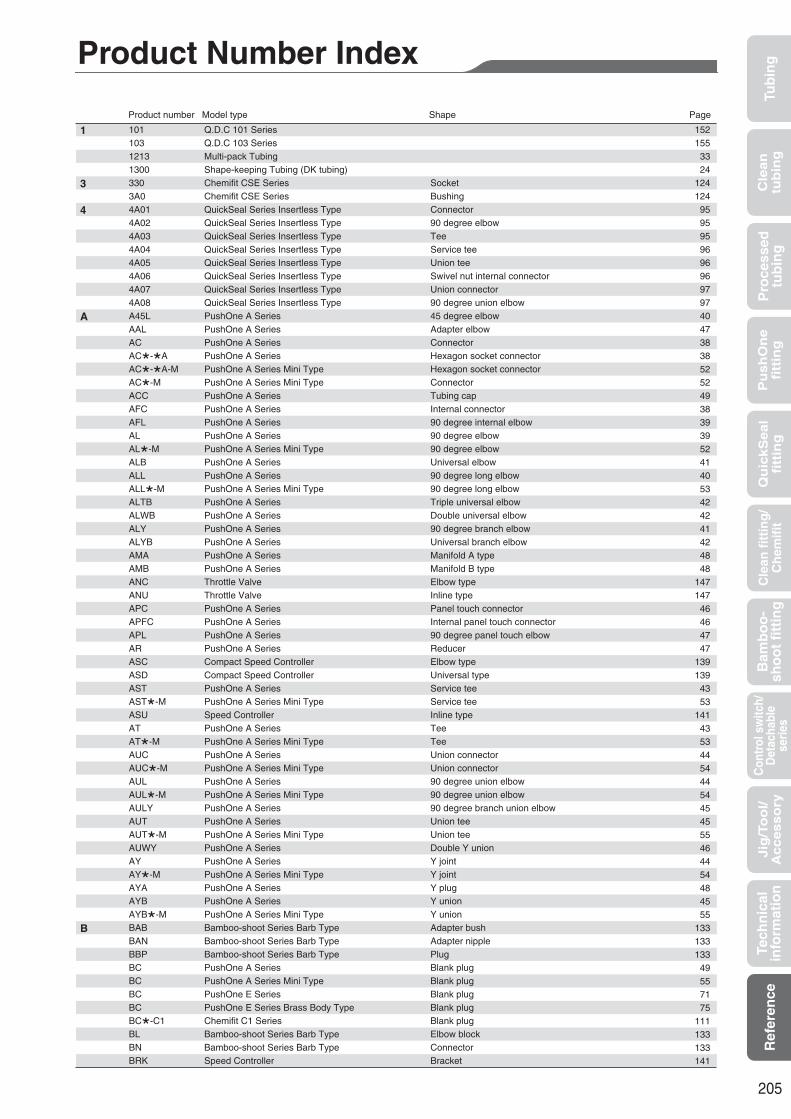
205
Tub
ing
Cle
an
tub
ing
Pu
sh
On
efi
ttin
gQ
uic
kS
ea
lfi
ttin
gB
amb
oo
-sh
oo
t fi
ttin
gC
ontr
ol s
witc
h/D
etac
habl
ese
ries
Cle
an f
itti
ng
/C
hem
ifit
Jig
/To
ol/
Accesso
ryR
efer
ence
Pro
cess
edtu
bin
gTe
chn
ical
info
rmat
ion
101 Q.D.C 101 Series 103 Q.D.C 103 Series 1213 Multi-pack Tubing 1300 Shape-keeping Tubing (DK tubing) 330 Chemifit CSE Series Socket3A0 Chemifit CSE Series Bushing4A01 QuickSeal Series Insertless Type Connector4A02 QuickSeal Series Insertless Type 90 degree elbow4A03 QuickSeal Series Insertless Type Tee4A04 QuickSeal Series Insertless Type Service tee4A05 QuickSeal Series Insertless Type Union tee4A06 QuickSeal Series Insertless Type Swivel nut internal connector4A07 QuickSeal Series Insertless Type Union connector4A08 QuickSeal Series Insertless Type 90 degree union elbowA45L PushOne A Series 45 degree elbowAAL PushOne A Series Adapter elbowAC PushOne A Series ConnectorAC*-*A PushOne A Series Hexagon socket connectorAC*-*A-M PushOne A Series Mini Type Hexagon socket connectorAC*-M PushOne A Series Mini Type ConnectorACC PushOne A Series Tubing capAFC PushOne A Series Internal connectorAFL PushOne A Series 90 degree internal elbowAL PushOne A Series 90 degree elbowAL*-M PushOne A Series Mini Type 90 degree elbowALB PushOne A Series Universal elbowALL PushOne A Series 90 degree long elbowALL*-M PushOne A Series Mini Type 90 degree long elbowALTB PushOne A Series Triple universal elbowALWB PushOne A Series Double universal elbowALY PushOne A Series 90 degree branch elbowALYB PushOne A Series Universal branch elbowAMA PushOne A Series Manifold A typeAMB PushOne A Series Manifold B typeANC Throttle Valve Elbow typeANU Throttle Valve Inline typeAPC PushOne A Series Panel touch connectorAPFC PushOne A Series Internal panel touch connectorAPL PushOne A Series 90 degree panel touch elbowAR PushOne A Series ReducerASC Compact Speed Controller Elbow typeASD Compact Speed Controller Universal typeAST PushOne A Series Service teeAST*-M PushOne A Series Mini Type Service teeASU Speed Controller Inline typeAT PushOne A Series TeeAT*-M PushOne A Series Mini Type TeeAUC PushOne A Series Union connectorAUC*-M PushOne A Series Mini Type Union connectorAUL PushOne A Series 90 degree union elbowAUL*-M PushOne A Series Mini Type 90 degree union elbowAULY PushOne A Series 90 degree branch union elbowAUT PushOne A Series Union teeAUT*-M PushOne A Series Mini Type Union teeAUWY PushOne A Series Double Y unionAY PushOne A Series Y jointAY*-M PushOne A Series Mini Type Y jointAYA PushOne A Series Y plugAYB PushOne A Series Y unionAYB*-M PushOne A Series Mini Type Y unionBAB Bamboo-shoot Series Barb Type Adapter bushBAN Bamboo-shoot Series Barb Type Adapter nippleBBP Bamboo-shoot Series Barb Type PlugBC PushOne A Series Blank plugBC PushOne A Series Mini Type Blank plugBC PushOne E Series Blank plugBC PushOne E Series Brass Body Type Blank plugBC*-C1 Chemifit C1 Series Blank plugBL Bamboo-shoot Series Barb Type Elbow blockBN Bamboo-shoot Series Barb Type ConnectorBRK Speed Controller Bracket
Product number Model type Shape Page
Product Number Index
1
3
4
A
B
152155
3324
124124
95959596969697974047383852524938393952414053424241424848
147147
46464747
139139
4353
141435344544454454555464454484555
133133133
49557175
111133133141

206
BRK Throttle Valve BracketBT Bamboo-shoot Series Barb Type Tee blockBUVL Bamboo-shoot Series Barb Type Universal elbow blockBUVT Bamboo-shoot Series Barb Type Universal tee blockC1N QuickSeal Series Insertion Type (brass) Connector (group 1)C1N*-S QuickSeal Series Insertion Type (stainless) Connector (group 1)C2N QuickSeal Series Insertion Type (brass) Connector (group 2)C4N QuickSeal Series Insertion Type (brass) Connector (group 4)C4N*-S QuickSeal Series Insertion Type (stainless) Connector (group 4)CP Spatter Cap CP-C* Chemifit CP Series ConnectorCPFW Spatter Cap CPI Chemifit CP Series Insertion partCP-L* Chemifit CP Series 90 degree elbowCPN Chemifit CP Series NutCPP Spatter Cap CPS Chemifit CP Series SleeveCP-ST* Chemifit CP Series Service teeCP-T* Chemifit CP Series TeeCP-UC* Chemifit CP Series Union connectorCP-UL* Chemifit CP Series 90 degree union elbowCP-UT* Chemifit CP Series Union teeCSAN Chemifit CSE Series Assembly nutCSE-C* Chemifit CSE Series ConnectorCSE-FC* Chemifit CSE Series Internal connectorCSE-L* Chemifit CSE Series 90 degree elbowCSE-ST* Chemifit CSE Series Service teeCSE-T* Chemifit CSE Series TeeCSE-UC* Chemifit CSE Series Union connectorCSE-UCT* Chemifit CSE Series Panel touch connectorCSE-UL* Chemifit CSE Series 90 degree union elbowCSE-UT* Chemifit CSE Series Union teeDC QuickSeal Series DK Tubing Dedicated Type ConnectorDL QuickSeal Series DK Tubing Dedicated Type 90 degree elbowDT QuickSeal Series DK Tubing Dedicated Type TeeDUP QuickSeal Series DK Tubing Dedicated Type Panel touch connector for copper pipeDUT QuickSeal Series DK Tubing Dedicated Type Panel touch connectorE45L PushOne E Series 45 degree elbowEAL PushOne E Series Adapter elbowEC PushOne E Series ConnectorEC*-*A PushOne E Series Hexagonal socket connectorEC*-C1 Chemifit C1 Series ConnectorEC*-C1S Chemifit C1S Series ConnectorECC PushOne E Series Tubing capECV Valve Built-in Connector EFC PushOne E Series Internal connectorEFL PushOne E Series 90 degree internal elbowEFC*-C1S Chemifit C1S Series Internal connectorEL PushOne E Series 90 degree elbowEL*-C1 Chemifit C1 Series 90 degree elbowEL*-C1S Chemifit C1S Series 90 degree elbowELB PushOne E Series Universal elbowELL PushOne E Series 90 degree long elbowELTB PushOne E Series Triple universal elbowELWB PushOne E Series Double universal elbowELY PushOne E Series 90 degree branch elbowELYB PushOne E Series Universal branch elbowEMA PushOne E Series Manifold A typeEMA*-C1 Chemifit C1 Series ManifoldEMB PushOne E Series Manifold B typeEMVA Miniature Valve (PushOne) Inline typeEMVB Miniature Valve (PushOne) Straight typeEMVC Miniature Valve (PushOne) Angled typeEN PushOne A Series NippleEN PushOne A Series Mini Type NippleEN PushOne E Series NippleEN PushOne E Series Brass body Type NippleEOT Off Tool EPC PushOne E Series Panel touch connectorEPC*-C1 Chemifit C1 Series Panel touch connectorEPC*-C1S Chemifit C1S Series Panel touch connector
Product number Model type Shape Page
B
C
D
E
147133133133
7890787890
161128161131128131161131129129130130130123120120121122121122123122123
999999
101100
61695858
106114
71151
5960
11459
107114
61606362626270
11170
149149149
49557175
16168
110116
Tub
ing
Cle
an
tub
ing
Pu
sh
On
efi
ttin
gQ
uic
kS
ea
lfi
ttin
gB
amb
oo
-sh
oo
t fi
ttin
gC
ontr
ol s
witc
h/D
etac
habl
ese
ries
Cle
an f
itti
ng
/C
hem
ifit
Jig
/To
ol/
Accesso
ryR
efer
ence
Pro
cess
edtu
bin
gTe
chn
ical
info
rmat
ion

207
Tub
ing
Cle
an
tub
ing
Pu
sh
On
efi
ttin
gQ
uic
kS
ea
lfi
ttin
gB
amb
oo
-sh
oo
t fi
ttin
gC
ontr
ol s
witc
h/D
etac
habl
ese
ries
Cle
an f
itti
ng
/C
hem
ifit
Jig
/To
ol/
Accesso
ryR
efer
ence
Pro
cess
edtu
bin
gTe
chn
ical
info
rmat
ion
EPFC PushOne E Series Internal panel touch connectorEPL PushOne E Series 90 degree panel touch elbowER PushOne E Series ReducerER*-C1 Chemifit C1 Series ReducerES Clean, Antistatic Tubing ESC*-C1SG Chemifit C1 Speed Controller Elbow typeEST PushOne E Series Service teeEST*-C1 Chemifit C1 Series Service teeEST*-C1S Chemifit C1S Series Service teeESU*-C1SG Chemifit C1 Speed Controller Inline typeET PushOne E Series TeeET*-C1 Chemifit C1 Series TeeET*-C1S Chemifit C1S Series TeeETC*-C1 Chemifit C1 Series Through connectorEUC PushOne E Series Union connectorEUC*-C1 Chemifit C1 Series Union connectorEUL PushOne E Series 90 degree union elbowEUL*-C1 Chemifit C1 Series 90 degree union elbowEULY PushOne E Series 90 degree branch union elbowEUT PushOne E Series Union teeEUT*-C1 Chemifit C1 Series Union teeEUWY PushOne E Series Double Y unionEY PushOne E Series Y jointEY*-C1 Chemifit C1 Series Y jointEY*-C1S Chemifit C1S Series Y jointEYA PushOne E Series Y plugEYB PushOne E Series Y unionEYB*-C1 Chemifit C1 Series Y unionFC1N QuickSeal Series Insertion Type (brass) Internal connector (group 1)FC4N QuickSeal Series Insertion Type (brass) Internal connector (group 4)FS Flame-resistant Tubing FUK Flame-resistant Tubing FW Flame-resistant Tubing FWU Flame-resistant Tubing HC03 Hose Cutter HPN Speed Controller Connector pinHPN Throttle Valve Connector pinHPN*-C1 Chemifit C1 Speed Controller Connector pinL1N QuickSeal Series Insertion Type (brass) 90 degree elbow (group 1)L1N*-S QuickSeal Series Insertion Type (stainless) 90 degree elbow (group 1)L2N QuickSeal Series Insertion Type (brass) 90 degree elbow (group 2)L4N QuickSeal Series Insertion Type (brass) 90 degree elbow (group 4)L4N*-S QuickSeal Series Insertion Type (stainless) 90 degree elbow (group 4)MEL PushOne E Series Brass Body Type 90 degree elbowMEST PushOne E Series Brass Body Type Service teeMET PushOne E Series Brass Body Type TeeMEUC PushOne E Series Brass Body Type Union connectorMEUL PushOne E Series Brass Body Type 90 degree union elbowMEUT PushOne E Series Brass Body Type Union teeMRG Bamboo-shoot Series Barb Type GasketMSN QuickSeal Series Insertion Type (brass) Brass sleeveMSN QuickSeal Series Insertless Type Brass sleeveN QuickSeal Series Insertion Type (brass) Brass nutN QuickSeal Series Insertless Type Brass nutN QuickSeal Series DK Tubing Dedicated Type Brass nutN*-S QuickSeal Series Insertion Type (stainless) Stainless nutN1 Nylon Tubing N2 Nylon Tubing N5 Nylon Tubing PB Polybutene Tubing PL Polyolefin Resin Tubing PN Polyolefin Resin Tubing PTR Tube Reel QMVA Miniature Valve (QuickSeal) Inline typeQMVB Miniature Valve (QuickSeal) Straight typeQMVC Miniature Valve (QuickSeal) Angled typeS Nylon Coil Tubing S*-ES* QuickSeal Series Nylon Coil tubing Dedicated Type ES swivel nut internal connectorS*-FS* QuickSeal Series Nylon Coil tubing Dedicated Type FS swivel nut internal connectorS*-M* QuickSeal Series Nylon Coil tubing Dedicated Type ConnectorS101 Q.D.C. 101 Series (SUS304)
Product number Model type Shape Page
E
F
H
L
M
N
P
Q
S
686969
11125
13764
108115137
63107115106
65109
66109
6667
1106865
108116
7067
110828220192122
159141147137
7990797990747474757575
13385978597
10193171516242627
161150150150
32103103102152

208
SBRK Chemifit C1 Speed Controller BracketSC1N QuickSeal Series Insertion Type (brass) Swivel nut internal connector (group 1)SC2N QuickSeal Series Insertion Type (brass) Swivel nut internal connector (group 2)SC4N QuickSeal Series Insertion Type (brass) Swivel nut internal connector (group 4)SI QuickSeal Series Nylon Coil Tubing Dedicated Type Insertion part for S 3/4SN QuickSeal Series DK Tubing Dedicated Type Nylon sleeveSN QuickSeal Series Insertion Type (brass) Nylon sleeveSN QuickSeal Series Insertion Type (stainless) Nylon sleeveSS QuickSeal Series Nylon Coil Tubing Dedicated Type Nylon sleeve / Brass sleeveST1N QuickSeal Series Insertion Type (brass) Service tee (group 1)ST1N*-S QuickSeal Series Insertion Type (stainless) Service tee (group 1)ST2N QuickSeal Series Insertion Type (brass) Service tee (group 2)ST4N QuickSeal Series Insertion Type (brass) Service tee (group 4)ST4N*-S QuickSeal Series Insertion Type (stainless) Service tee (group 4)T1N QuickSeal Series Insertion Type (brass) Tee (group 1)T1N*-S QuickSeal Series Insertion Type (stainless) Tee (group 1)T2N QuickSeal Series Insertion Type (brass) Tee (group 2)T4N QuickSeal Series Insertion Type (brass) Tee (group 4)T4N*-S QuickSeal Series Insertion Type (stainless) Tee (group 4)TA Fluorocarbon Resin Tubing TC01 Tube Cutter TC02 FW Tubing Outer Cover Peeling Cutter TC02U FWU Tubing Outer Cover Peeling Cutter TC03 FW Tubing Outer Cover Peeling Cutter TC03U FWU Tubing Outer Cover Peeling Cutter TC04 Tube Cutter TES Flexible Fluorocarbon Resin Tubing TP Fluorocarbon Resin Tubing U1 Polyurethane Tubing U2 Polyurethane Tubing U5 Polyurethane Tubing UC Polyurethane Coil Tubing UC1N QuickSeal Series Insertion Type (brass) Union connector (group 1)UC1N*-S QuickSeal Series Insertion Type (stainless) Union connector (group 1)UC4N QuickSeal Series Insertion Type (brass) Union connector (group 4)UC4N*-S QuickSeal Series Insertion Type (stainless) Union connector (group 4)UCT1N QuickSeal Series Insertion Type (brass) Panel touch connector (group 1)UCT4N QuickSeal Series Insertion Type (brass) Panel touch connector (group 4)UDC QuickSeal Series DK Tubing Dedicated Type Union connectorUDT QuickSeal Series DK Tubing Dedicated Type Union teeUE Anti static Tubing UL1N QuickSeal Series Insertion Type (brass) 90 degree union elbow (group 1)UL4N QuickSeal Series Insertion Type (brass) 90 degree union elbow (group 4)UL4N*-S QuickSeal Series Insertion Type (stainless) 90 degree union elbow (group 4)UMC Polyurethane Coil Tubing UML Polyurethane Multi-line Tubing USC Polyurethane Coil Tubing UT1N QuickSeal Series Insertion Type (brass) Union tee (group 1)UT1N*-S QuickSeal Series Insertion Type (stainless) Union tee (group 1)UT2N QuickSeal Series Insertion Type (brass) Union tee (group 2)UT4N QuickSeal Series Insertion Type (brass) Union tee (group 4)UT4N*-S QuickSeal Series Insertion Type (stainless) Union tee (group 4)VA Ball Valve Angled typeVS Ball Valve Straight type
Product number Model type Shape Page
S
T
U
V
137848484
103101
8593
1038191818191809180809128
159160160160160159
182913121430829282928484
100100
238383923031308392838392
145144
Tub
ing
Cle
an
tub
ing
Pu
sh
On
efi
ttin
gQ
uic
kS
ea
lfi
ttin
gB
amb
oo
-sh
oo
t fi
ttin
gC
ontr
ol s
witc
h/D
etac
habl
ese
ries
Cle
an f
itti
ng
/C
hem
ifit
Jig
/To
ol/
Accesso
ryR
efer
ence
Pro
cess
edtu
bin
gTe
chn
ical
info
rmat
ion

Tubing, Fitting and CHEMIFIT
TM
7605 Nitta Drive, Suwanee,GA 30024, U.S.A.Phone:+1-770-497-0212 Fax:+1-770-623-1398https://www.nitta.com
Room 2705, Shenggao International Building, No.137 Xianxia Road, Shanghai 200051, P.R.CHINAPhone:+86-21-6229-6000 Fax:+86-21-6229-9606http://www.nitta.com.cn/index.php?s=/
Chia Hsin Building, 10FL, Room No. 1005, 96 Chung Shan North Road Section 2,Taipei,TAIWAN Phone:+886-2-2581-6296 Fax:+886-2-2563-4900https://www.nitta.com.tw
Heerdter Lohweg 35, 40549 Dusseldorf,GERMANYPhone:+49-211-537535-0 Fax:+49-211-537535-35https://www.nitta.de
Gat No.191, 192, and 193, Plot No B, Village Vadhu Khurd,Taluka Haveli Dist Pune-412216, INDIAPhone:+91-20-6731-3400 Fax:+91-20-6731-3401https://www.nitta.co.in
7/472 Moo 6,Tambol Mabyangporn, Amphur Pluadaeng,Rayong Province 21140, THAILAND Phone:+66-38-018-301 Fax:+66-38-018-304https://www.nittathai.com
4-4-26 Sakuragawa Naniwa-ku,Osaka 556-0022 JAPAN Phone:+81-6-6563-1241 Fax:+81-6-6563-1243
https://www.nitta.co.jp/en
2101200U