general information - great plains information these instructions explain how to install the...
TRANSCRIPT
Great Plains Mfg., Inc.
Installation Instructions 1
Electro-Hydraulic Control OptionGreat Plains 3-Point Sprayers
Used with:
• CF500 Cross-Fold Boom• CF600 Cross-Fold Boom
General Information
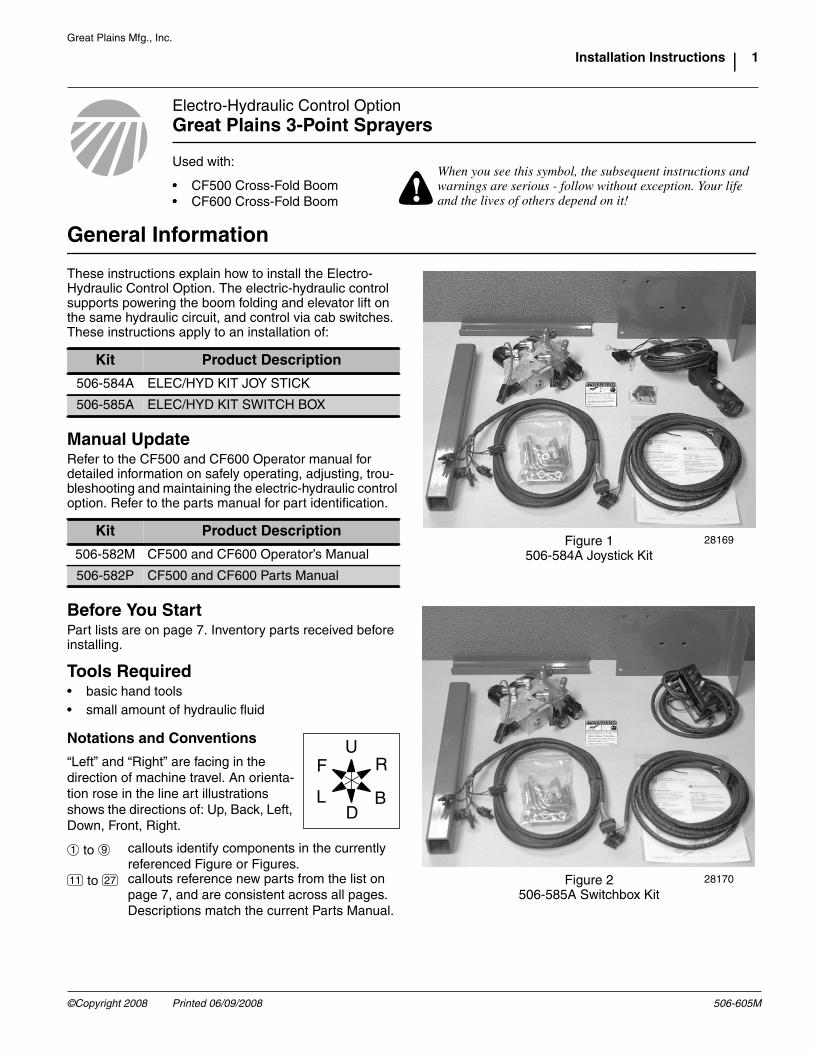
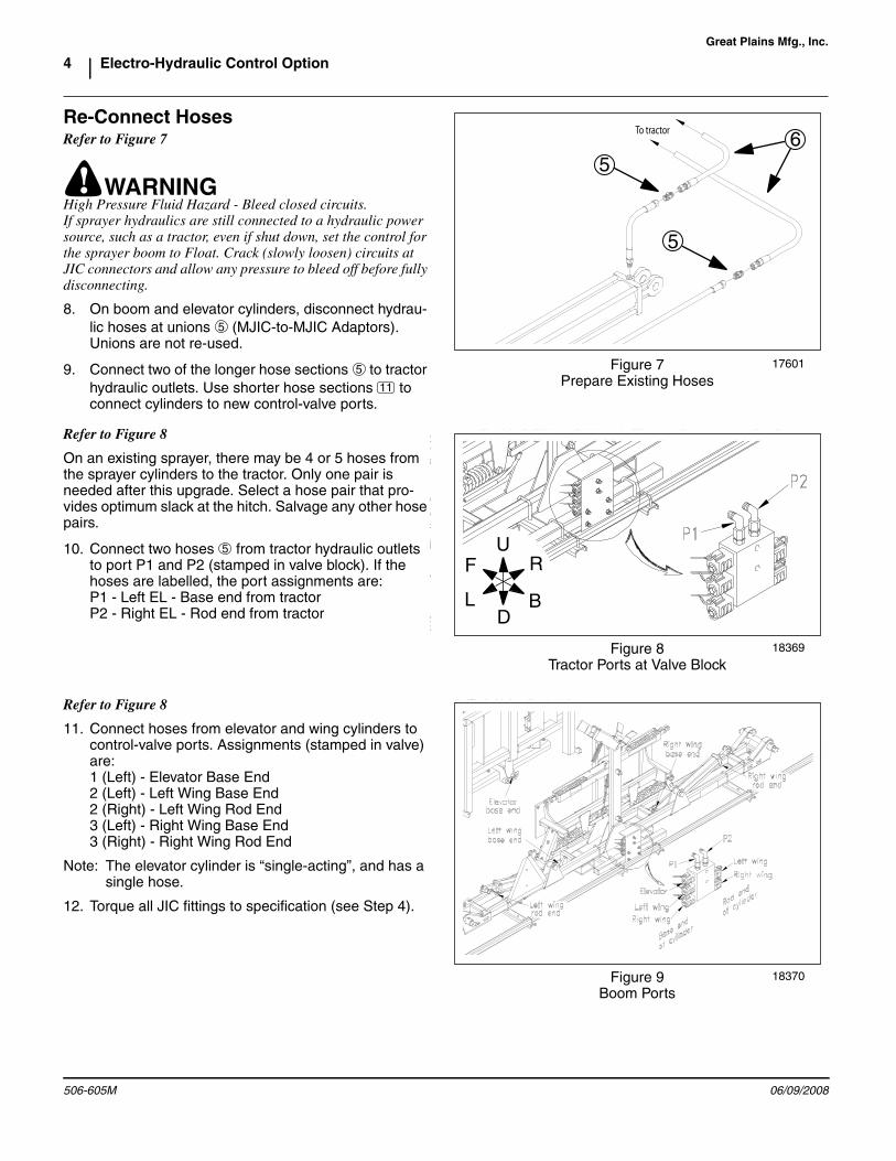
These instructions explain how to install the Electro-Hydraulic Control Option. The electric-hydraulic controlsupports powering the boom folding and elevator lift onthe same hydraulic circuit, and control via cab switches.These instructions apply to an installation of:
Manual UpdateRefer to the CF500 and CF600 Operator manual fordetailed information on safely operating, adjusting, trou-bleshooting and maintaining the electric-hydraulic controloption. Refer to the parts manual for part identification.
Before You StartPart lists are on page 7. Inventory parts received beforeinstalling.
Tools Required• basic hand tools• small amount of hydraulic fluid
Kit Product Description
506-584A ELEC/HYD KIT JOY STICK
506-585A ELEC/HYD KIT SWITCH BOX
Kit Product Description
506-582M CF500 and CF600 Operator’s Manual
506-582P CF500 and CF600 Parts Manual
Notations and Conventions
“Left” and “Right” are facing in thedirection of machine travel. An orienta-tion rose in the line art illustrationsshows the directions of: Up, Back, Left,Down, Front, Right.
to callouts identify components in the currentlyreferenced Figure or Figures.
to callouts reference new parts from the list onpage 7, and are consistent across all pages.Descriptions match the current Parts Manual.
!When you see this symbol, the subsequent instructions andwarnings are serious - follow without exception. Your lifeand the lives of others depend on it!
Figure 1506-584A Joystick Kit
28169
Figure 2506-585A Switchbox Kit
28170
U
DL
R
B
F
1 9
11 27
©Copyright 2008 Printed 06/09/2008 506-605M

Great Plains Mfg., Inc.
2 Electro-Hydraulic Control Option
Assembly Instructions
Mount Tube BracketRefer to Figure 31. Select one each:
506-357D C-SECTION NOZZLE TUBE BRACKET 806-001C U-BOLT 3/8-16 X 2 X 4 806-107C U-BOLT 5/16-18 X 1 17/32X2 1/8
and two sets: 803-068C NUT HEX FLANGE 3/8-16 PLT 803-199C NUT HEX FLANGE 5/16-18 PLT
Position mounting bracket the same distance toleft of center posts as existing mounting bracketis to right of posts.
Use 3/8in hardware ( , ) at boom frame, and5/16in hardware ( , ) at nozzle tube.
Prepare valve and BracketRefer to Figure 6If the decal is already applied, skip to Step 3.
2. Select one each: 510-022D FASSE VALVE BLOCK MTG PLATE 818-339C DECAL WARNING HIGH PRESSUR SML
Clean and dry the back side of the bracket . Peelthe backing paper from the decal . With thebracket break up and away from you, position thedecal at the upper left corner. Apply it. Smooth outany air bubbles by applying pressure with a cleancloth.
If the elbows are already installed, skip to Step 5.
3. Select one each: 833-215C FASSE VALVE BLOCK ASSY 302-451
and two: 811-169C EL 9/16MJIC 9/16FJIC
Install the elbows on the end ports of the valveblock, facing away from the back of the valve.
4. Apply some hydraulic fluid to the cone and threads ofthe male fittings. Torque 9/16 JIC fittings to 18-20 ft-lbs (24-27 N-m).
Figure 3Mounting Bracket
17525
12
1
2
34
17
20
16
18
U
DL
R
B
F
12
18
20
16
17
12
3 4
18 16
20 17
Figure 4Decal and Elbows
28172
14
22
2321
14
22
14
22
23
21
21
506-605M 06/09/2008

Great Plains Mfg., Inc.
Installation Instructions 3
Refer to Figure 55. Select two sets:
802-216C HHCS 3/8-16X2 3/4 GR5 803-068C NUT HEX FLANGE 3/8-16 PLT
With the break of the bracket up, orient the valveblock with the elbows up and the back of thevalve block against the bracket.
Insert the bolts from the front of the valve block,and secure with nuts .
Install ValveRefer to Figure 66. Select one:
506-368D TUBE ELEC/HYD MTG FOR CF600and two:
806-004C U-BOLT 3/8-16 X 2 X 2 3/4and two sets:
803-068C NUT HEX FLANGE 3/8-16 PLT
Place the tube under the valve on the bracket ,and secure with U-bolts and nuts . Center thebracket on the tube.
7. Select two: 806-004C U-BOLT 3/8-16 X 2 X 2 3/4
and two sets: 803-068C NUT HEX FLANGE 3/8-16 PLT
Orient valve block facing forward, with break inbracket at top.
Secure tube to new and existing nozzle tubebracket , using U-bolts and nuts .
Figure 5Mount Control Valve
18369
23
14
1516
U
DL
R
B
F
21
15
16
14
23 21
15
16
Figure 6Install Control Valve
18366
13
19
16
14
U
DL
R
B
F
416
16
13
19
16
13 14
19 16
19
16
14
13 12
4 19 16
06/09/2008 506-605M
Great Plains Mfg., Inc.
4 Electro-Hydraulic Control Option
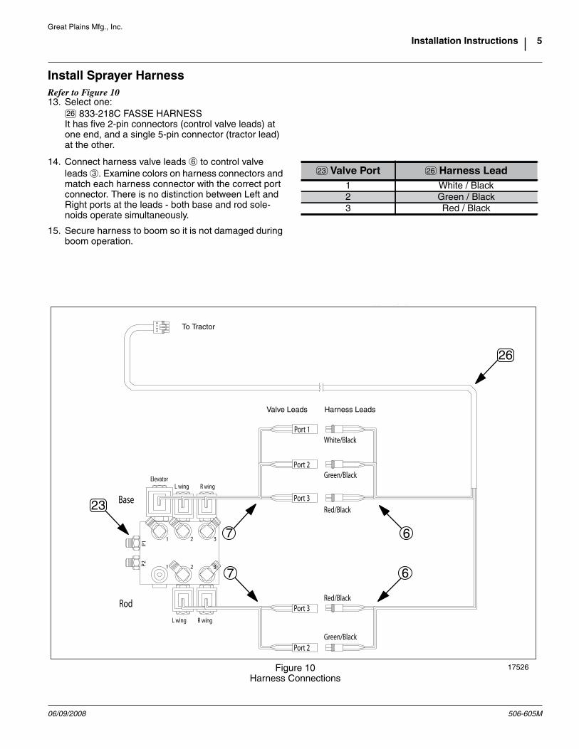
Re-Connect HosesRefer to Figure 7
! WARNINGHigh Pressure Fluid Hazard - Bleed closed circuits.If sprayer hydraulics are still connected to a hydraulic powersource, such as a tractor, even if shut down, set the control forthe sprayer boom to Float. Crack (slowly loosen) circuits atJIC connectors and allow any pressure to bleed off before fullydisconnecting.
8. On boom and elevator cylinders, disconnect hydrau-lic hoses at unions (MJIC-to-MJIC Adaptors).Unions are not re-used.
9. Connect two of the longer hose sections to tractorhydraulic outlets. Use shorter hose sections toconnect cylinders to new control-valve ports.
Refer to Figure 8
On an existing sprayer, there may be 4 or 5 hoses fromthe sprayer cylinders to the tractor. Only one pair isneeded after this upgrade. Select a hose pair that pro-vides optimum slack at the hitch. Salvage any other hosepairs.
10. Connect two hoses from tractor hydraulic outletsto port P1 and P2 (stamped in valve block). If thehoses are labelled, the port assignments are:P1 - Left EL - Base end from tractorP2 - Right EL - Rod end from tractor
Refer to Figure 8
11. Connect hoses from elevator and wing cylinders tocontrol-valve ports. Assignments (stamped in valve)are:1 (Left) - Elevator Base End2 (Left) - Left Wing Base End2 (Right) - Left Wing Rod End3 (Left) - Right Wing Base End3 (Right) - Right Wing Rod End
Note: The elevator cylinder is “single-acting”, and has asingle hose.
12. Torque all JIC fittings to specification (see Step 4).
Figure 7Prepare Existing Hoses
17601
5
5
6
5
5
11
Figure 8Tractor Ports at Valve Block
18369
U
DL
R
B
F5
Figure 9Boom Ports
18370
506-605M 06/09/2008
Great Plains Mfg., Inc.
Installation Instructions 5
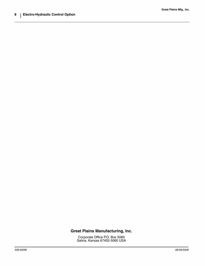
Install Sprayer HarnessRefer to Figure 1013. Select one:
833-218C FASSE HARNESSIt has five 2-pin connectors (control valve leads) atone end, and a single 5-pin connector (tractor lead)at the other.
14. Connect harness valve leads to control valveleads . Examine colors on harness connectors andmatch each harness connector with the correct portconnector. There is no distinction between Left andRight ports at the leads - both base and rod sole-noids operate simultaneously.
15. Secure harness to boom so it is not damaged duringboom operation.
Figure 10Harness Connections
17526
To Tractor
Valve Leads
67
67
Harness Leads
26
23
Valve Port Harness Lead1 White / Black2 Green / Black3 Red / Black
23 26
26
6
3
06/09/2008 506-605M

Great Plains Mfg., Inc.
6 Electro-Hydraulic Control Option
Install Cab ComponentsRefer to Figure 1116. Select one:
833-216C FASSE HANDLE RCS ASSY 1020Cor
833-217C FASSE SWITCH BOXdepending on kit ordered.
17. Mount valve controller in tractor cab.
If the kit contains a joystick controller , selectappropriate U-bolt fasteners from suppliedassortment, and secure the controller to the hydrau-lic remote lever for boom operations.
If kit contains a switch box , mount box in anaccessible location in tractor cab. Kit includesbracket, but does not include mounting fasteners.
18. Connect power leads from controller to a 12-volt,negative-ground power source. To prevent valvefrom draining tractor battery, connect power leads tofuse panel, key switch or other source that is notenergized when tractor is off. Connect red lead topositive (+) terminal and black lead to negative (-)terminal or other ground.
19. Route controller harness to hitch and mate withsprayer harness. If slack is insufficient, select one:
833-219C FASSE HARNESS EXTENSION
Insert it in the circuit to provide more slack. Tie upany excess cable so that it cannot touch the groundduring operations (or when the tractor used withother implements).
20. Secure harness to tractor so it is not damaged dur-ing tractor and boom operations.
Figure 11Cab Connections
17526
9
To Sprayer
8
24
25
27
24
25
24
8
25
9
27
506-605M 06/09/2008

Great Plains Mfg., Inc.
Installation Instructions 7
Operations
Refer to Figure 12Switch box switches are 2-position toggles.Joystick switches are 2-position push-button.They remain in their currently selected status untilchanged.
When power is being supplied to the controller, an indi-cator lamp at each switch is on if the switch is engagedand power is being supplied to the assigned solenoids.An indicator is off is the switch is off, or power is off.
The switch assignments are:
The hydraulic circuit lever is normally left in the Neutralposition, to hold the cylinder positions. To fold/unfold orlift/lower, engage the switch for that cylinder, and operatethe lever.
Cylinders may be operated individually or as groups.
Parts List
506-584A ELEC/HYD KIT JOY STICK506-585A ELEC/HYD KIT SWITCH BOX
Switch Color (Valve Port) Cylinder Controlled
Green Left Boom Fold/Unfold Yellow Elevator Lift/Lower Red Right Boom Fold/Unfold
CalloutPart
NumberQuantity in Kit 506-
DescriptionTorqueValue506-584A 506-585A
506-605M 1 1 MANUAL FASSE VALVE INSTALL506-357D 1 1 C-SECTION NOZZLE TUBE BRACKET506-368D 1 1 TUBE ELEC/HYD MTG FOR CF600510-022D 1 1 FASSE VALVE BLOCK MTG PLATE802-216C 2 2 HHCS 3/8-16X2 3/4 GR5 31 ft-lbs / 32 N-m803-068C 12 12 NUT HEX FLANGE 3/8-16 PLT 31 ft-lbs / 32 N-m803-199C 2 2 NUT HEX FLANGE 5/16-18 PLT 17 ft-lbs / 24 N-m806-001C 1 1 U-BOLT 3/8-16 X 2 X 4 31 ft-lbs / 32 N-m806-004C 4 4 U-BOLT 3/8-16 X 2 X 2 3/4 31 ft-lbs / 32 N-m806-107C 1 1 U-BOLT 5/16-18 X 1 17/32X2 1/8 17 ft-lbs / 24 N-m811-169C 2 2 EL 9/16MJIC 9/16FJIC 18-20 ft-lbs / 24-27 N-m818-339C 1 1 DECAL WARNING HIGH PRESSUR SML833-215C 1 1 FASSE VALVE BLOCK ASSY 302-451833-216C 1 FASSE HANDLE RCS ASSY 1020C833-217C 1 FASSE SWITCH BOX833-218C 1 1 FASSE HARNESS833-219C 1 1 FASSE HARNESS EXTENSION
Figure 12Switch Functions
28173
Y
G R
G Y R
G 2
Y 1
R 3
11
12
13
14
15
16
17
18
19
20
21
22
23
24
25
26
27
06/09/2008 506-605M
Great Plains Mfg., Inc.
8 Electro-Hydraulic Control Option
506-605M 06/09/2008
Great Plains Manufacturing, Inc.Corporate Office P.O. Box 5060
Salina, Kansas 67402-5060 USA