general information on battery electric vehicles general
TRANSCRIPT

Work on electric power take-off (PTO EL)
General information on battery electric vehiclesGeneral information on battery electric ve-hiclesThis document contains information on vehicles powered by battery electricity and the electric power take-off that these vehicles are fitted with. The electric power take-off is currently available on battery electric vehicles (BEV) and plug-in hybrid elec-tric vehicles (PHEV).
Battery electric vehicles are powered by an electric motor and battery power as the energy source. The energy is stored in lithium batteries. Battery electric vehicles do not have a combustion engine, whereas for example plug-in hybrid electric vehicles can be powered by both an electric motor and a combustion engine.
Battery electric vehicles have 2 electrical systems, one of which has VCA, 24 V (voltage class A) and the other VCB, 650 V (voltage class B):
Battery electric vehicles should be considered low-voltage systems >60 V and <1,500 V (DC). This means that everyone who manufactures, distributes or installs electrical equipment must ensure that the work and equipment satisfy the relevant safety requirements for each market.
Follow the safety precautions under the headings Safety precautions and standards and Chassis modifications on electric vehicles. This also applies if only mechanical work is carried out or if work is only carried out in the 24 V system and no work is carried out on the VCB system.
When working in the workshop, the battery electric vehicle must be positioned so that it can be driven out in the event of a fire or other risk without obstruction.
More information on safety regulations can be found in the following document:
Electrical system DC (direct current) AC (alternating current)VCA 0-60 V 0-30 VVCB 60-1,500 V 30-1,000 V
Scania Truck Bodybuilder 22:10-834 Issue 2 2021-11-11© Scania CV AB 2021, Sweden 1 (32)

General information on battery electric vehicles
Work on electric power take-off (PTO EL)
• Work on battery electric vehicles• Working with hybrid vehicles
Scania Truck Bodybuilder 22:10-834 Issue 2 2021-11-11© Scania CV AB 2021, Sweden 2 (32)

General information on battery electric vehicles
Work on electric power take-off (PTO EL)
Safety precautions and standardsIMPORTANT!
• Save the results of the insulation measurements and display on request• Save test results and test reports that verify that electrical systems and compo-
nents connected to the electric power take-off comply with the requirements.
The following standards must be followed for bodywork VCB components and their installation:
• ISO6469-3• UN standard 10 (R10) and standard 100 (R100)• Only CE labelled components may be used
The vehicle is delivered certified in accordance with UN standard 10 and standard 100 with factory-fitted CE marked components. It is the responsibility of the body-builder to ensure that the vehicle is certified after the bodywork has been completed.
More information can be found under the heading "Electrical requirements for sys-tems and components connected to the electric power take-off". It must be possible to present test results and test reports on request.
Scania Truck Bodybuilder 22:10-834 Issue 2 2021-11-11© Scania CV AB 2021, Sweden 3 (32)

General information on battery electric vehicles
Work on electric power take-off (PTO EL)
Chassis modifications on electric vehiclesWARNING!
Modification of the VCB system is prohibited. The VCB components or their cable harnesses, which are orange coloured, must not be moved or changed in any way af-ter the vehicle has been delivered. All work in the vicinity of VCB components and their cable harnesses must be carried out with caution.
Taking current from or connecting units to the propulsion batteries is prohibited, ex-cept via the electric power take-off.
More information on work on VCB systems can be found in the following document:
• Work on battery electric vehicles• Working with hybrid vehicles
Scania Truck Bodybuilder 22:10-834 Issue 2 2021-11-11© Scania CV AB 2021, Sweden 4 (32)

Position of electric power take-off and its components
Work on electric power take-off (PTO EL)
A
B
1
2
1
2
3
4
442
503
Position of electric power take-off and its componentsScania's battery electric vehicles may be factory-fitted with the Electric power take-off (PTO-EL) (variant code 8932A) option, which makes it possible to connect the bodywork to the VCB system. The connection is made via a terminal box (1) that provides access to the direct current supply from the vehicle's VCB batteries.
On battery electric vehicles, the fuse box (2) and the terminal box for connecting to bodywork are located at the rear edge under the cab; see illustration detail (A).
On plug-in hybrid electric vehicles, the fuse box and the terminal box are positioned inside the frame behind the third crossmember; see illustration detail (B).
Pos Designation Description1 Terminal box R126 Contactor unit for electric power take-off2 Fuse box P14 Fusebox for electric power take-off3 BMU control unit Control unit for the rechargeable energy stor-
age system (fitted to the underside of the frame)4 BCI control unit Bodywork communication interface. Factory-
fitted in the cab on vehicles fitted with the Bod-ywork communication interface (BCI) (variant code 5837A) option.
Scania Truck Bodybuilder 22:10-834 Issue 2 2021-11-11© Scania CV AB 2021, Sweden 5 (32)

Position of electric power take-off and its components
Work on electric power take-off (PTO EL)
2
3
1
435
594
Terminal box R126 for electric power take-offPos Designation Description1 Voltage supply Incoming voltage supply from the vehicle's
VCB system2 Bodybuilder connection,
positive voltage supplyConnection point for electric power take-off, positive voltage supply
3 Bodybuilder connection, negative voltage supply
Connection point for electric power take-off, negative voltage supply
Scania Truck Bodybuilder 22:10-834 Issue 2 2021-11-11© Scania CV AB 2021, Sweden 6 (32)
Electric power take-off description and function
Work on electric power take-off (PTO EL)
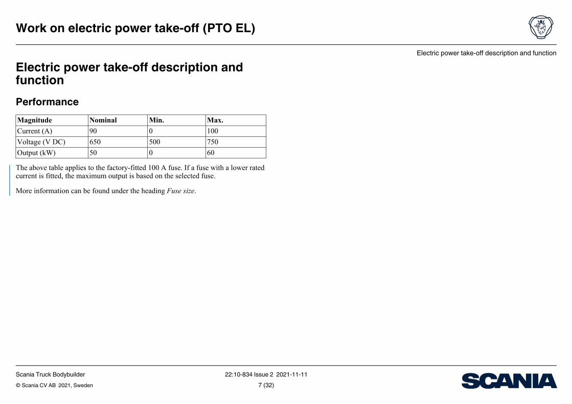
Electric power take-off description and functionPerformance
The above table applies to the factory-fitted 100 A fuse. If a fuse with a lower rated current is fitted, the maximum output is based on the selected fuse.
More information can be found under the heading Fuse size.
Magnitude Nominal Min. Max.Current (A) 90 0 100Voltage (V DC) 650 500 750Output (kW) 50 0 60
Scania Truck Bodybuilder 22:10-834 Issue 2 2021-11-11© Scania CV AB 2021, Sweden 7 (32)

Electric power take-off description and function
Work on electric power take-off (PTO EL)
General function• Activation can only be carried out when the 15 voltage1 is active. The power take-
off can be activated if the 15 voltage is switched off.• Activation can only be carried out once every 30 seconds• The power take-off can be used when the propulsion batteries are being charged• If the power take-off is used when the propulsion batteries are being charged and
charging is interrupted, the power take-off may still be active. It is possible for the bodybuilder to build in logic that allows the power take-off to remain active after charging has been interrupted.
• The power take-off is not deactivated due to low battery level. It is possible to set the power take-off activation and deactivation conditions via a logic that uses the SOC (State Of Charge) of the propulsion batteries.
• If the bodywork is connected to the grid, the power take-off must be deactivated automatically.
• Charging the propulsion batteries via the bodywork is prohibited if the electric power take-off is activated.
• If the bodywork's VCB components are water-cooled, they can be connected to the vehicle's cooling circuit. The connection requires approval from Scania.
• The power take-off is controlled via the BCI control unit. More information can be found under the heading General information about activating and deactivat-ing PTO EL.
1. Voltage activated when the starter lock is in drive mode.
Scania Truck Bodybuilder 22:10-834 Issue 2 2021-11-11© Scania CV AB 2021, Sweden 8 (32)
Using PTO EL
Work on electric power take-off (PTO EL)
Using PTO ELIMPORTANT!
• The electrical power take-off must be unloaded when activation or deactivation is requested. The contactors will be damaged if they open and cut high currents.
• The bodywork's VCB system must be de-energised when activating the power take-off. This may lead to interrupted activation and fault code generation.
The bodywork's electric power consumption is also monitored by protective software with the following limit values and consequences if the limits are exceeded:
• Electric power consumption above 100 A for more than 2 seconds results in a re-quest from the vehicle to reduce the load on PTO EL; if this does not occur, de-activation will take place within 8 seconds
• Electric power consumption above 150 A for longer than 30 milliseconds results in an emergency shutdown of PTO EL
Scania Truck Bodybuilder 22:10-834 Issue 2 2021-11-11© Scania CV AB 2021, Sweden 9 (32)
Using PTO EL
Work on electric power take-off (PTO EL)
General information about activation/deactivation of PTO ELThe bodywork must have functionality to handle a deactivation request for the elec-trical power take-off from the vehicle. This includes ramping down the load and ac-tive discharging of the VCB circuit.
The number of activations/deactivations of the electrical power take-off must be minimised as this affects the service life of the contactors.
It is recommended that the power take-off is activated at the start of the working shift and left activated until the work shift is over even if the bodywork is not active during certain periods.
When PTO EL is activated, this is displayed via an indicator lamp in the instrument cluster (ICL).
The following flow charts show different sequences for activating/deactivating PTO EL; all sequences are controlled via BMU:
• Activation• Deactivation• Deactivation initiated by the chassis• Emergency deactivation
As standard, vehicles are delivered without a switch for activating the power take-off. However, it is possible to install a switch that controls the activation via BCI functionality.
Scania Truck Bodybuilder 22:10-834 Issue 2 2021-11-11© Scania CV AB 2021, Sweden 10 (32)

Using PTO EL
Work on electric power take-off (PTO EL)
A B C
1a
1b
1c
1d
2
3a
3b
3c
4a
4b
4c
444
289
Flow chart for activating PTO EL.A: Bodywork, B: Terminal box R126, C: BMU/BCIColour designationBlack: Bodywork VCBGreen: CAN or BICT signalsPurple: The vehicle's internal signalsBlue: Internal process
Activating PTO EL1. Prerequisites
• Bodywork VCB system deactivated (1a)• No energy consumption from the bodywork's VCB system (1b)• PTO EL status "Ready" (1c)• Bodywork VCB system ready for activation (1d)
2. Request to activate PTO EL via BICT or CAN from Bodywork (2)
3. Activation sequence initiated• Pre-charging VCB system (3a)• Result pre-charging (3b)• Diagnostics, all parameters OK (3c)
(Includes contactor function and detection of breaks/short circuits; see section Electrical requirements for systems and components con-nected to electric power take-off for requirements)
4. PTO EL activation• PTO EL is activated by closing the contactors (4a)• Bodywork VCB system activated (4b)• PTO EL status "Active" (4c)
Scania Truck Bodybuilder 22:10-834 Issue 2 2021-11-11© Scania CV AB 2021, Sweden 11 (32)

Using PTO EL
Work on electric power take-off (PTO EL)
A B C
1a
1b
2
3a
3b3c
4a
4b
4c
5
444
326
Flow chart for activating PTO EL.A: BodyworkB: Terminal box R126C: BMU/BCIColour designationBlack: Bodywork VCBGreen: CAN or BICT signalsPurple: The vehicle's internal signalsBlue: Internal process
Deactivation of PTO EL1. Prerequisites
• Bodywork VCB system activated (1a)• PTO EL status "Active" (1b)
2. Request for deactivation of PTO EL via BICT or CAN from Body-work (should only happen when necessary to minimise contactor wear)
(2)
3. Deactivation sequence initiated• PTO EL status "Deactivated" in the event that the vehicle initiates
deactivation(3a)
• Maximum deactivation delay 10 seconds (3b)• The bodywork's VCB system must be unloaded within 10 seconds.
If this does not happen, an emergency shutdown will be carried out and the vehicle must be restarted before PTO EL can be reacti-vated
(3c)
4. PTO EL deactivation• PTO EL is deactivated via opening the contactors (4a)• Bodywork VCB system deactivated (4b)• PTO EL status "Deactivated" (4c)
5. Active discharging of the bodywork's VCB system (5)(see the section General requirements)
Scania Truck Bodybuilder 22:10-834 Issue 2 2021-11-11© Scania CV AB 2021, Sweden 12 (32)

Using PTO EL
Work on electric power take-off (PTO EL)
A B C
1a
1b
2a
2b2c
3a
3b
3c
4
444
700
Flow chart for activating PTO EL.A: BodyworkB: Terminal box R126C: BMU/BCIColour designationBlack: Bodywork VCBGreen: CAN or BICT signalsPurple: The vehicle's internal signalsBlue: Internal process
Deactivation of PTO EL initiated by the chassis1. Prerequisites
• Bodywork VCB system activated (1a)• PTO EL status "Active" (1b)
(Request for deactivation of PTO EL initiated by the chassis due to a fault in the VCB system)
2. Deactivation sequence initiated• PTO EL status "Deactivated" (2a)• Maximum deactivation delay 10 seconds (2b)• The bodywork's VCB system must be unloaded within 10 seconds.
If this does not happen, an emergency shutdown will be carried out and the vehicle must be restarted before PTO EL can be reacti-vated
(2c)
3. PTO EL deactivation• PTO EL is deactivated via opening the contactors (3a)• Bodywork VCB system deactivated (3b)• PTO EL status "Deactivated" (3c)
4. Active discharging of the bodywork's VCB system (4)(see the section General requirements)
Scania Truck Bodybuilder 22:10-834 Issue 2 2021-11-11© Scania CV AB 2021, Sweden 13 (32)

Using PTO EL
Work on electric power take-off (PTO EL)
A B C
1a
1b
2
3a
4a
4b
4c
5
444
701
Flow chart for activating PTO EL.A: BodyworkB: Terminal box R126C: BMU/BCIColour designationBlack: Bodywork VCBGreen: CAN or BICT signalsPurple: The vehicle's internal signalsBlue: Internal process
Deactivation of PTO EL in an emergency1. Prerequisites
• Bodywork VCB system activated (1a)• PTO EL status "Active" (1b)
(Request for deactivation of PTO EL initiated by the chassis due to a fault in the VCB system)
2. Deactivation sequence initiated• PTO EL status "Deactivated" (2a)• Maximum deactivation delay 10 seconds (2b)• The bodywork's VCB system must be unloaded within 10 seconds.
If this does not happen, an emergency shutdown will be carried out and the vehicle must be restarted before PTO EL can be reacti-vated
(2c)
3. PTO EL deactivation• PTO EL is deactivated via opening the contactors (3a)• Bodywork VCB system deactivated (3b)• PTO EL status "Deactivated" (3c)
4. Active discharging of the bodywork's VCB system (4)(see the section General requirements)
Scania Truck Bodybuilder 22:10-834 Issue 2 2021-11-11© Scania CV AB 2021, Sweden 14 (32)

Using PTO EL
Work on electric power take-off (PTO EL)
Signal value Description
0x01: Ready PTO EL is not activated but ready to be activated when the vehicle's propulsion system is activated, provided all other requirements are satisfied
0x00: NotReady PTO EL is not active and is not ready to be activated0x03: Deactivating The deactivation sequence for PTO EL has started; this
can be initiated by the bodywork or by the chassis if a fault is detected in the VCB system The bodywork's VCB system must be unloaded within 10 seconds. If this does not happen, an emergency shutdown will be carried out and the vehicle must be restarted before PTO EL can be reactivated
0x02: Activated PTO EL is activated0x04: Emergency Deactivated
PTO EL has undergone an emergency deactivation and the vehicle must be restarted before PTO EL can be re-activated
Signals for checking PTO ELBICT: Signal name Swedish
BICT: Signal name English
CAN signal
PTO EL ready PTO EL ready PTOInformationProp::PTO_EL
- -PTO EL deactivated PTO EL deactivating
PTO EL engaged PTO EL activatedPTO EL emergency deactivated
PTO EL emergency deactivated
Scania Truck Bodybuilder 22:10-834 Issue 2 2021-11-11© Scania CV AB 2021, Sweden 15 (32)

Using PTO EL
Work on electric power take-off (PTO EL)
Signal value Description
0x00: NotReady The propulsion system is activated, which is a require-ment for activating PTO EL
0x01: Ready Replaces previous signals "the alternator is charging", "the engine is running", etc. but without any connec-tion to which propulsion system the vehicle has. Can be used on all Vehicles, even those with a combustion engine
0x02: Starting0x03: Stopping
y 0-100% Propulsion battery state of charge. PTO EL will not be deactivated due to a low charge level, but it is possible to program a battery level warning via BCI functional-ity
0x00: NotActive Propulsion battery state of charge low is also displayed in the instrument cluster
0x01: Active
Other relevant signalsBICT: Signal name Swedish
BICT: Signal name English
CAN signal
Vehicle start active Propulsion state ready
DLN9::PropulsionState
Propulsion battery state of charge
Propulsion battery state of charge
HybridInfoProp::StateOfChargeDispla
Propulsion battery state of charge low
Low state of charge indication
HybridInfoProp::LowChargeIndication
Scania Truck Bodybuilder 22:10-834 Issue 2 2021-11-11© Scania CV AB 2021, Sweden 16 (32)

Using PTO EL
Work on electric power take-off (PTO EL)
Signal value Description
uest(Activate) 0x01 Activation can only be carried out if PTO EL status is "PTO EL ready" Among other things, the activation sequence checks for a break or short circuit in the bodywork's VCB sys-tem. It is therefore important that the bodywork's VCB system satisfies the electrical requirements (refer to the section on electrical requirements)PTO EL will remain active as long as the signal is ac-tive
uest(Deactivate) 0x00 Deactivation request, which means that the bodywork must unload the VCB system within 10 seconds to minimise contactor wear. If this does not happen, an emergency shutdown will be carried out and the vehi-cle must be restarted before PTO EL can be reactivated
uest(Emergency 0x02 PTO EL will be deactivated regardless of whether there is load on the connection. This should only be done in an emergency due to the risk of wear/damage to the components in PTO EL. The vehicle must be re-started before PTO EL can be reactivated
uest(Take No 0x03 No active request
PTO EL control signals
More information on BCI and electric power take-off control can be found in the fol-lowing document:
• BCI - Bodywork Communication Interface• External CAN Communication Specification
BICT: Signal name Swedish
BICT: Signal name English
CAN
Activate PTO EL Activate PTO EL BodyworkPTOControl::PTO_EL_Req
Deactivate PTO EL Deactivate PTO EL BodyworkPTOControl::PTO_EL_Req
Emergency deactivate PTO EL
Emergency deacti-vate PTO EL
BodyworkPTOControl::PTO_EL_ReqDeactivate)
- - BodyworkPTOControl::PTO_EL_ReqAction)
Scania Truck Bodybuilder 22:10-834 Issue 2 2021-11-11© Scania CV AB 2021, Sweden 17 (32)

Using PTO EL
Work on electric power take-off (PTO EL)
General requirementsIMPORTANT!
• The bodywork must never generate a higher voltage than the VCB voltage in the vehicle. It is prohibited to return power to the vehicle's VCB system.
• Position bodywork electrical equipment so that cables are as short as possible. Short cables mean a reduced risk of EMC1interference and installation problems.
• All VCB components must comply with applicable standards regarding electrical safety and comply with ingress protection class IP6K7 or IP6K9K depending on the location on the vehicle. This also applies to connected connectors. Connectors that can be disconnected without tools must also comply with IPXXB (R100) when they are not connected.
• The vehicle's insulation status is monitored using an insulation monitoring device (IMD). It is prohibited to have an active IMD in the bodywork when the electric power take-off is activated. This applies if the bodywork VCB system is galvan-ically connected to the vehicle's VCB system.
• The bodywork VCB system must be galvanically separate from bodywork earth and the VCA system. An insulation test should be carried out in accordance with ECE-R100, ISO 6469-1, ISO 6469-3.
• All electrical VCB connections in the bodywork must be designed to prevent un-intentional polarity reversal
• The bodywork VCB system must have passive discharging, which means that the voltage drops below 60 V within 5 minutes of deactivation of the power take-off
• The bodywork VCB system must have active discharging, which means that the voltage drops below 60 V within 3 seconds of deactivation of the power take-off. This applies when requesting from the vehicle or detecting an open circuit.
• All VCB components must have electrically conductive casing
1. The equipment's ability to function satisfactorily in its electromagnetic environment without causing unacceptable electromagnetic interference for other equipment.
Scania Truck Bodybuilder 22:10-834 Issue 2 2021-11-11© Scania CV AB 2021, Sweden 18 (32)

Connection to electric power take-off
Work on electric power take-off (PTO EL)
Connection to electric power take-offWARNING!
This work is classified as electrical work and may only be carried out by trained and qualified personnel who are authorised to perform electrical work with approved pro-tective equipment.It is prohibited to carry out work on the electric power take-off before the following actions have been taken:• Disconnect the voltage supply from the VCB batteries using the control switch for
the VCB system; see points 1 to 3 in the following list• Carry out a voltage measurement on the incoming voltage supply with an ap-
proved result; see point 5 in the following list
Scania Truck Bodybuilder 22:10-834 Issue 2 2021-11-11© Scania CV AB 2021, Sweden 19 (32)
Connection to electric power take-off
Work on electric power take-off (PTO EL)
436
791
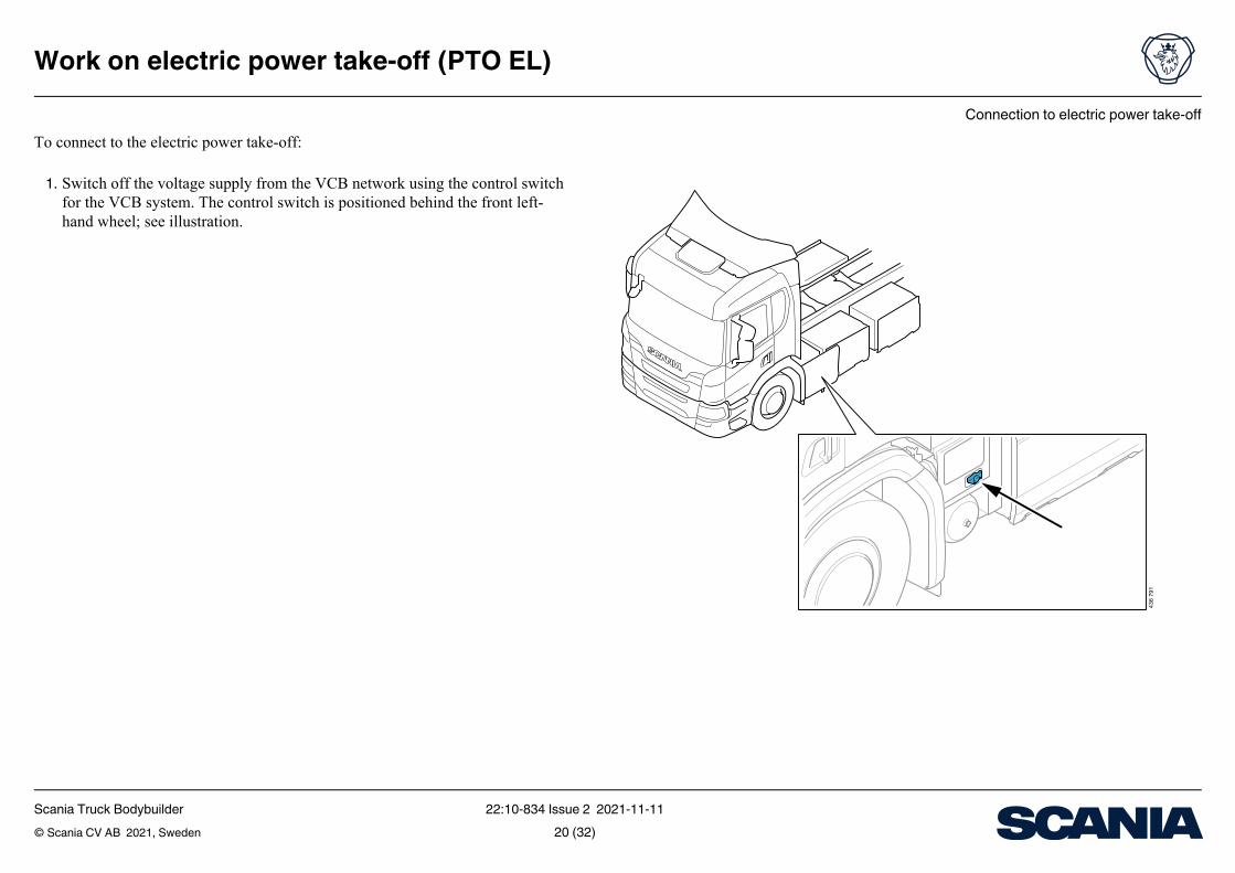
To connect to the electric power take-off:
1. Switch off the voltage supply from the VCB network using the control switch for the VCB system. The control switch is positioned behind the front left-hand wheel; see illustration.
Scania Truck Bodybuilder 22:10-834 Issue 2 2021-11-11© Scania CV AB 2021, Sweden 20 (32)

Connection to electric power take-off
Work on electric power take-off (PTO EL)
436
792
2. Lock the control switch in the off position with a padlock; see illustration
3. Check that the VCB system is switched off as follows:– Check that the vehicle cannot be started– Switch on the 15 voltage by turning the starter lock to drive mode– Check that the error message Engine start inhibited, electric drive system is
disconnected is displayed in the instrument cluster
Scania Truck Bodybuilder 22:10-834 Issue 2 2021-11-11© Scania CV AB 2021, Sweden 21 (32)

Connection to electric power take-off
Work on electric power take-off (PTO EL)
436
793
4. Open the terminal box by removing both covers; see illustration. Do this care-fully so as not to damage the gasket. Note that the fuse box located on top of the terminal box must be removed in order to open the terminal box. This must be done without detaching Scania's VCB connections.
Scania Truck Bodybuilder 22:10-834 Issue 2 2021-11-11© Scania CV AB 2021, Sweden 22 (32)

Connection to electric power take-off
Work on electric power take-off (PTO EL)
1
435
596
5. Make sure that the voltage supply is cut by measuring the voltage between the positive rail and negative rail on the incoming voltage supply; see illustration. The voltage level must < 5 volts for an approved result. Also measure on the outgoing connections in the terminal box.
6. Remove the plugs on the side of the terminal box (1); see illustration
7. Connect the cables prepared for the bodywork at the designated point. Make sure that the bodywork is connected with the correct polarity. Fit the cable fit-tings. Use the following tightening torque:
– Negative connection M10, tightening torque: 19.2 Nm– Positive connection M8, tightening torque: 9.6 Nm– Tightening torque, cable fitting: 15 Nm
8. Measure and document the insulation value for the bodywork9. Refit the inner protective cover, tightening torque: 2.4 Nm
10. Check the seal and refit the terminal box cover, tightening torque: 4 Nm
Scania Truck Bodybuilder 22:10-834 Issue 2 2021-11-11© Scania CV AB 2021, Sweden 23 (32)

Connection to electric power take-off
Work on electric power take-off (PTO EL)
Fuse sizeIMPORTANT!
The new fuse must be of the same make and from the same series as the factory-fitted fuse. Refer to the table below.
The vehicle is factory-fitted with a 100 A fuse. Switching to a fuse with a lower rated current is permitted if this is required to better match the bodywork's prevailing elec-tric power consumption. Contact your local Scania workshop for more information.
The cable harness cross-sectional area is selected according to the prevailing rated current on the fuse according to the table below, which indicates the minimum per-missible conductor cross-sectional area.
It is also necessary to select a cable fitting that fits the outer diameter of the selected cable to secure the cable grommet seal.
Fuse size Mersen part number Cable cross-sectional area (mm²)
50 MEV100A50-4Y 660 MEV100A60-4Y 1070 MEV100A70-4Y 1280 MEV100A80-4Y 1290 MEV100A90-4Y 16
100 MEV100A100-4Y 16
Scania Truck Bodybuilder 22:10-834 Issue 2 2021-11-11© Scania CV AB 2021, Sweden 24 (32)

Connection to electric power take-off
Work on electric power take-off (PTO EL)
Fitting cable fittings and ring terminals to the elec-tric power take-off
IMPORTANT!
VCB cables must be shielded. The shield must be connected to the connector or the component's casing.
The cable cross-sectional area for VCB cables must be as per the table under the heading Fuse size and be orange-coloured. The cables must comply with ISO 6722 and ISO 19642.
Ring terminals and press tools must be from the same supplier.
More information on which screws, washers and cable fittings with strain relief to use can be found under the heading Part information.
Scania Truck Bodybuilder 22:10-834 Issue 2 2021-11-11© Scania CV AB 2021, Sweden 25 (32)

Connection to electric power take-off
Work on electric power take-off (PTO EL)
12
34
5 6 7
444
253
The following table and illustration gives an overview of cable fitting components.
The illustration shows the position of the various components in relation to the cable parts when the fitting is installed.
The seal (Pos 3) must be positioned on the outer jacket of the cable and the spring (Pos 4) must be positioned on the cable shield.
Pos Designation Description1 Cable VCB Shielded cable for VCB2 Pressure screw Screw for compressing seal and attaching electrical
cable3 Seal Seal between the electrical cable's outer jacket and
the cable fitting4 Spring Earth connection between cable shield and cable fit-
ting5 Cable shield Cable shield for earthing6 Fitting to terminal
boxThread to terminal box M32x1.5
7 O-ring Seal to terminal box
Scania Truck Bodybuilder 22:10-834 Issue 2 2021-11-11© Scania CV AB 2021, Sweden 26 (32)

Connection to electric power take-off
Work on electric power take-off (PTO EL)
444
252
Reducer with seal to the terminal box.
IMPORTANT!
Depending on the dimension selected for the cable fitting, it may be necessary to fit a reducer from the terminal box thread to the relevant thread on the fitting. The max-imum thread length to the terminal box is 8 mm; see illustration.
Fit cable fittings and ring terminals to the electric power take-off as follows:
1. Strip off the appropriate length of the outer jacket of the cable and the part of the shield where the ring terminal will be fitted. Wind insulation tape around the end of the shield to protect it from damage. The cable fitting seal should be around the outer jacket of the cable and the cable fitting spring should be around the ca-ble shield.
2. Insert the cable into the cable grommet while rotating it slightly. Do not tighten the pressure screw.
3. Press the ring terminal into place in accordance with the manufacturer's instruc-tions
4. Fit the cable grommet in the terminal box.5. Tighten the pressure screw.
Scania Truck Bodybuilder 22:10-834 Issue 2 2021-11-11© Scania CV AB 2021, Sweden 27 (32)

Connection to electric power take-off
Work on electric power take-off (PTO EL)
1
2
3
436
794
Example of connection of equipotential bonding earth conductor in chassis:1. The bodywork's VCB components are connected to a common earthing point in
the bodywork2. Bodywork earth screw is connected to designated earth screw M10 in the right-
hand or left-hand frame side member3. Electric power take-off
Connection to earthing in chassis (equipotential bonding)
IMPORTANT!
The casing of all VCB components in the bodywork must be electrically connected to the designated earth screw in the chassis. The equipotential bonding ensures that no dangerous potential differences occur and protects against dangerous situations in the event of a short circuit.
Connect equipotential bonding as follows:
• Connect a black multi-wire conductor with a cable cross-section of 25 mm² to designated earth screw M10 in the chassis
• The maximum number of connections per earth screw is 3. Connecting several components to an internal connection point in the bodywork is permitted.
• Perform a continuity measurement and document for all connected components• If possible, position the earth cable together with other VCB cables in the vehicle
Scania Truck Bodybuilder 22:10-834 Issue 2 2021-11-11© Scania CV AB 2021, Sweden 28 (32)

Connection to electric power take-off
Work on electric power take-off (PTO EL)
Cable routing requirementsThe following requirements apply specifically to VCB cable harnesses:
• Clamping VCB cables together with VCA cables is prohibited• The minimum permitted distance between a connection point on VCB cables and
VCA cables during parallel connection is 100 mm• The longest permitted distance between a connection point on a VCB component
and the first clamping point on a VCB cable is 150 mm• The longest permitted distance between clamping points for VCB cables is
300 mm• Position the entire VCB cable harness in an orange protection hose• Positive and negative conductors should be positioned together. It is also recom-
mended that the cable for equipotential bonding is positioned together with a pos-itive and negative conductor where possible.
• If possible, position the bodywork VCB cable harness together with the vehicle's VCB cable harness. Use existing brackets and cable ducts for VCB cables where possible.
• The electrical connection between the cable shield and VCB components must be ensured by measuring resistance
• Perform a continuity measurement and record the result. The maximum permitted value including contact points is 50 mOhm.
• Follow the cable manufacturer's instructions regarding the maximum permitted bend radius for cables
More information is found in the document Working with cables and lead throughs.
Scania Truck Bodybuilder 22:10-834 Issue 2 2021-11-11© Scania CV AB 2021, Sweden 29 (32)
Connection to electric power take-off
Work on electric power take-off (PTO EL)
s during and after the tests during and after the test, but some functions may exceed permissible tolerances during the test. Memory functions must comply with Status A.
eet the specifications during the test, but automatically return to normal after the testeet the specifications during the test and do not return to normal without a simple reset
Statuseen the positive terminal and earthing on the chas-nd earthing on the chassis; test pulse 1,000 V
The insulation value should be greater than 10 mOhmThe insulation value should be greater than 25 mOhm. This also applies when the components have reached their ex-pected service life
with ISO/PAS 19295:2016 -
according to IEC 60664-1:2020. Test voltage: Function status B/C
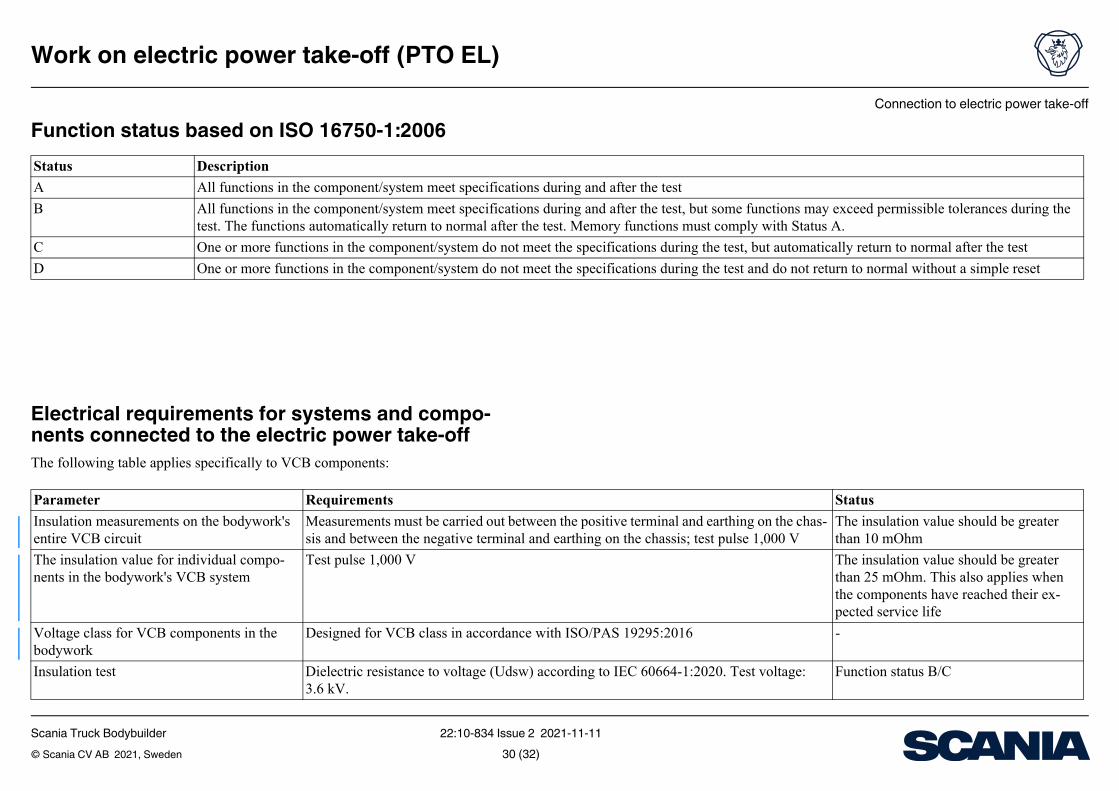
Function status based on ISO 16750-1:2006
Electrical requirements for systems and compo-nents connected to the electric power take-offThe following table applies specifically to VCB components:
Status DescriptionA All functions in the component/system meet specificationB All functions in the component/system meet specification
test. The functions automatically return to normal after theC One or more functions in the component/system do not mD One or more functions in the component/system do not m
Parameter RequirementsInsulation measurements on the bodywork's entire VCB circuit
Measurements must be carried out betwsis and between the negative terminal a
The insulation value for individual compo-nents in the bodywork's VCB system
Test pulse 1,000 V
Voltage class for VCB components in the bodywork
Designed for VCB class in accordance
Insulation test Dielectric resistance to voltage (Udsw)3.6 kV.
Scania Truck Bodybuilder 22:10-834 Issue 2 2021-11-11© Scania CV AB 2021, Sweden 30 (32)

Connection to electric power take-off
Work on electric power take-off (PTO EL)
C 60664-1:2020. Test voltage: 4 kV. Function status B/Cns) according to ISO 6469-3:2018 section 10.3.2. Function status B/C
k VCB system for normal use according to ISO No permanent faults or insulation resist-anceFunction status AFunction status B/C
to ISO 21498-2 750-770 V function status B 770-930 V function status C 930-1,045 V function status C/D
g to ISO 21498-2 500-450 V function status B 450-225 V function status C
enerate voltage variations greater than 15 Vtt dur- Applies to frequency range 10-150 kHz in accordance with ISO 21498-2 Section 6.5
- 4 2020 section 4.6. Test voltage according to test Function status A
- 4 2020 section 4.6. Test voltage according to test Function status A
le to handle at least 5 pulses according to ISO each test pulse is permitted.
Function status D
D and between VCB - and GND Maximum permitted value: 50 nFCB - Minimum permitted value: 0.1 mF Maxi-
mum permitted value: 1 mFMaximum permitted value: 5 μH
interference must comply with UNECE Reg. 10 -
Status
Insulation test Resistance to voltage pulses (Uimn) IEInsulation test Insulation resistance measurements (UiTest voltage: 1 kV.Dielectric resistance Connect, earth and secure the bodywor
6469-3Supply voltage VCB supply voltage 500-750 VOvervoltage VCB supply voltage 930 V for 1 hourTemporary overvoltage Overvoltage on VCB supply according
Temporary overvoltage Undervoltage on VCB supply accordin
Voltage variations from the bodywork VCB system
The bodywork VCB system must not ging operation
Surge voltage on VCB supply Test pulse A according to ISO/TS 7637 level 3.
Transient undervoltage on VCB supply Test pulse B according to ISO/TS 7637 level 3.
Interruption to VCB supply The bodywork VCB system must be ab21498-2. Resetting the system between
Bodywork VCB capacitance Y capacitance between VCB + and GNBodywork VCB capacitance X capacitance between VCCB + and V
Bodywork VCB inductance Inductance between VCB + and VCB -Electromagnetic compatibility High-frequency conducted and radiated
and CISPR 25:2016
Parameter Requirements
Scania Truck Bodybuilder 22:10-834 Issue 2 2021-11-11© Scania CV AB 2021, Sweden 31 (32)

Connection to electric power take-off
Work on electric power take-off (PTO EL)
Variant code8932A5837A
g
-c r
d x
Ordering options
Part information
Scania does not supply these items.
Option AlternativePTO EL electric power take-off WithBodywork communication interface (BCI) With
Designation DescriptionScrew M10×20 Negative connection in terminal box; use parts accordin
to designation or equivalent adapted for electrical joints.Applies to both negative and positive connections.
Washer M10 shape S
Screw M8×20 Positive connection in terminal boxWasher M8 shape SBlueglobe Tri EMC M32 (Pflitsch make)
Cable fitting; use parts according to designation or equivalent. Note that the fitting must be EMC (Electro MagnetiCompatibility) classified with an electrical connection fothe cable shield. The dimension of the fitting must be adapted to the relevant cable dimension. Any reducer useto adapt the thread on the cable fitting to the terminal bothread must be sealed.
Scania Truck Bodybuilder 22:10-834 Issue 2 2021-11-11© Scania CV AB 2021, Sweden 32 (32)