general instructions for 8” dredges - kellyco detectors · fig 1j winch and safety chain is used...
TRANSCRIPT

1
General Instructions for 8” dredges Read all instructions carefully and assemble dredge as per diagram. Ensure that all bolts, nuts and clamps are firmly tightened. 1. ASSEMBLE FRAME, ATTACH FLOATS AND SLUICE AS PER DIAGRAM AND ATTACHED FIGURES F1 TO F10. 2. INSTALL FUEL TANK AND CONNECT FUEL LINE: Install fuel tank and connect the fuel line. The fuel line must be routed with caution to the fuel pump located just below the carburetor. Avoid any contact to moving engine parts such as pulleys and the engine exhaust tubing. (FIG 2A & FIG 2B) 3. CONNECT POWER JET FLARE TO SLUICE BOX: First screw sluice box adjustment turn buckles to closed winch in middle position or shortest position and attach them to the center support gas tank support bracket as per diagram. 4. ATTACH PRESSURE HOSE TO POWER JET: Before attaching the power jet to the flared section ensure that the gaskets are in place. Attach the pressure hose to the power jet 5. ATTACH POWER JET ONTO JET FLARE: Once the pressure hoses are attached to the power jet, it is ready to attach to the power jet flare. The power jet must be pushed into the flare clamp section as illustrated on the diagram firmly and fitted to avoid any openings or leaks. This procedure will require the assist of a helper. One must hold the power jet firmly into the clamp section while the other tightens the bolts with a wrench. If a leak occurs, it may be remedied by filling the gap with a small amount of silicone rubber cement. 6. ATTACH THE SUCTION HOSE TO THE POWER JET: This is accomplished easily by opening the clamp section of the power jet and sliding the suction hose into the jet clamp and closing the clamp. For a proper fit, insure that the suction hose has a clean flat cut and fits flush against the inside of the jet. In some cases the outside of the hose may have a slightly smaller diameter and it may be necessary to wrap the outside of the hose with ducting tape or some type of tape that will slightly increase the outside diameter to insure a snug fit. 7. BATTERY PREPARATION AND ATTACHMENT: The battery is always shipped in a dry condition, as per shipping regulations of most common carriers. In order to activate the battery and make it usable, it must be filled with an electrolyte fluid provided at most battery supply stations. The electrolyte solution is not provided with the dredge. Caution, electrolyte liquid is a form of corrosive sulfuric acid and care must be exercised to avoid any body contact. The battery once filled is then placed in the provided battery container and charged. Attach the supplied battery leads. The positive lead wire attaches to the positive lead on the battery and the other end attaches to the starter lead. The negative lead attaches to the bottom bolt on the pump. Once the battery is fully charged and all connections fastened to their proper leads, place the cover on the battery and fasten under the pump as indicated in the attached diagram and fasten down securely with the provided rubber cords. 8. ASSEMBLING THE PUMP INTAKE SYSTEM: The intake section of the pump is attached by a short section of 5 inch hose and is held together with 6 each hose clamps. This section is supported by a tube support bracket and is bolted to the frame as illustrated in diagram. Care must be taken to insure that no air leaks occur in either

2
the intake or the discharge of the pump. An air leak in the intake system can prevent pump from priming. Priming simply means that all air is evacuated from the pump and intake system and is filled with water. If a leak exists when tightening a fitting or clamp, it is sometimes remedied by using silicone sealer or Teflon tape. 9. BEFORE STARTING ENGINE: Always check engine oil level before starting. Check fuel filter for evidence of dirt or other particles blocking fuel flow. Before starting engine check to see that all items are clear from exposed pulleys, belts and any moving parts including your hands, hair or any part of your body. Make sure that the gas petcock valve on the gas tank is open. As closed valve will prevent fuel from flowing into the carburetor. Make a final check to see if there are no leaks and all valves are closed. 10. PRIMING THE PUMP: To prime the pump the engine must be started and running at a low idle. Turn key to start. DO NOT RUN ENGINE FOR ANY PROLONGED PERIOD OF TIME WITHOUT PRIMING THE PUMP. Damage could result to the water pump seal. The water pump seal is a mechanical type and must have water to keep it lubricated and cool. Remove the cap located on the top of the foot valve and fill with water. Keep filling the foot valve until the water overflows. Replace the cap and tighten down. Your pump should now be primed. If all of your connections are tight, the pump should remain primed for several days. 11. SLUICE BOX OPERATION (See diagram) The sluice box is designed with four different recovery sections. The first section is designed to recover all of the course gold and nuggets. This is a flared section of open riffles that widens into approximately 35 inches. The second section designed to recover medium to fine values, containing a set of shorter riffles with a perforated classifier screen that is elevated above the riffles to classify and carry the larger aggregate to the next stage of recovery. The third section of the upper riffles is the final recovery of medium to fine gold that may have escaped the previous sections of the sluice. The fourth and final recovery of the sluice is designed to recover any super fine gold that may have escaped the first previous recovery sections. All fine values that are minus 3/8ths of an inch in size are fed into a lower riffle section containing still smaller riffles and a section of expanded metal or screen for more precise selection of fine gold recovery. This section has an adjustable slide tray for regulating the amount of water and material that enters this section of riffles. For the proper opening adjustment, we recommend that you start with the slide tray open about 8" from the end of the sluice. If the lower section is not holding any material, the tray must be slid in slightly. This adjustment must be determined by the nature of the area being dredged. Adjustments will vary according to conditions of the gravel that exists in your area. 12. FINAL CLEAN UP OF RECOVERED VALUES: The sluice system is self-cleaning and can be operated for extended periods of time. The average clean up of values is normally accomplished at the end of each day. This will vary depending on the types of gravel conditions and the size of the recovered values. In areas where heavy black sand exists, the sluice may have to be cleaned out more frequently. The sluice can be checked for the occurrence of values at any time without cleaning by simply by observing the first few riffles at the beginning of the sluice box. Experimentation in any new area is essential. 13. SUCTION TIP (See diagram) The suction tip is equipped with a swivel for ease of operation and is recommended to occasionally lubricate with a light oil for insured O Ring life. The suction tip is also equipped with a suction breaking rubber flap that is necessary to break the suction when a large or irregular rock becomes stuck to the end of the tip. Without this suction breaking flap, it would be nearly impossible remove an obstruction.


FIG 1A Front main frame support with rope tie downs
FIG 1D install ladder float frame at various locations.Can be positioned nearly anywhere on frame.
FIG 1E install outrigger support assembly FIG 1F install outrigger side support assemblymount on opposite side of dredge.
FIG 1I Connect winch and chains to supportsluice box ladder.
FIG 1H Assemble sluice box ladder to frame andbolt and bolt to rear frame support (Fig 1C).
FIG 1G Assembly sluice box ladder to frane andbolts to fig.1C rear sluice box frame support.
FIG 1B Center frame support FIG 1C Rear Sluice box and frame suport adjustableheight for adjusting end of sluice.
Rope Tie Downs

FIG 1J Winch and safety chain is usedto raise and lower sluice box assembly.
FIG 1M Attach foot valve support brackets toengine frame.
FIG 1L install front decks and install jet support chainsafter engine is bolted securly into place.
FIG 1K Install engine to mountingbrackets on frame deck.
FIG 1N Shown is further detail of foot valvelocation and brackets.
FIG 1O Connect pressure hose support to frame.
Jet support chain connectors

FIG 2A Diesel Fuel line assembly FIG 2B Diesel fuel return line inserted into top of tank.FIG 2C Typical Air Snorkel attachmet to aircompressors and air pressure hose assembly
FIG 2D Air snorkel mounted on end offreame reduces chance of air contamination.
OPTIONAL CANOPY $895.00 Dimensions : 10’ (3.048m) x 10’ (3.048m) x 20’ (6.096m)Custom canopy mounting enables the use of a 10 foot wide x 20 foot long canopy providing sunand rain protection.Equipped with powder coated 1 3/8ths. steel frame with six removable legsExhaust extension and necessary hardware to attach. A hole must be cut in canopy for toaccommodate exhaust discharge.

8040 & 8080 Basic FrameTop View

8040 & 8080 Basic FrameSide View
Top View of sluice ladder. The sluice box mounts ontop of the labber.
Sluice ladder
The Main dredge frame comes pre assembledwith the floats attached to the frame sections

2S2S2S2S
8040 MAIN SLUICE BOX - SIDE VIEW
8040 MAIN SLUICE BOX - PLAN VIEW
1SDETAILNO. 2SDETAIL
NO.
Carpet is tucked under the riffle and up the sides
Riffle drops into the sluice
Water flow

8040 POWER JET PLUMBINGFVA5
PI500
PHC4F
(2) HDC4P
(2) HDC4PT
PH4
(2) HDC3P
(2) HDC3P
SP433
PH3
(2) HDC3P
(2) HDC3P
DIESEL ENGINE
(2) 263 COMPRESSORS PJ84 ( 8"X 3"X 3")
3" VENTURIINJECTOR LOG
SQC83" VENTURIINJECTOR LOG

2
There are two air supply systemsthat are used for underwater divingactivities. One system, known as SelfContained Underwater BreathingApparatus (SCUBA), involves the useof high pressure metal tanks whichare worn on the diver's back whilediving. The equipment used inSCUBA diving is quite technical innature, and SCUBA gear should notbe used by persons who have notbecome a certified diver involvingspecialized instruction. Without a cer-tification card indicating completion ofsuch a course, you cannot purchasecompressed air.
Of course, the SCUBA air systemhas its advantages as well. A diverusing SCUBAgear is literally "an enti-ty unto himself," since he carries hislife giving air supply on his back at alltimes. He can go anywhere he choos-es, completely free of any ties withthe world topside.
There are many times when anunderwater diver does not need thetotal freedom that is afforded by theS C U B A air system, particularly incases in which the diver is sub-
merged in a limited area for long peri-ods of time.
For these applications, the"Hookah" (Surface Air Supply) wasinvented. The The Hookah air sys-tem uses no high pressure air tanksof the type worn on a diver's backInstead, it uses a small air compres-sor which is located at the surface. Itis commonly powered by a portablegasoline engine or electric motor, andthe air is delivered to the diver via afloating air hose. With the Hookahsystem, the diver has an unlimitedand nearly "cost free" air supplywhich will only stop flowing when theengine or motor that powers the com-pressor ceases to operate. T h i smakes for a truly economical air sys-tem, which will quickly pay for itselfwhen compared to the cost of refillinga SCUBA tanks every hour or so.
The only operating cost for aHookah system is fuel, since the vastmajority of Hookah compressor unitsare gasoline powered. It is notuncommon to get two hours divingtime on a single gallon of gas, whichshows just how economical the
Hookah air system can be. Most Hookah divers will have a
partner working "topside" as a safetyman, and he can refill the engine'sgas tank as it starts getting low. Thiswill enable the diver to stay sub-merged so long as he desires.
THE AIR COMPRESSOR
Introduction to Hookah Diving
Typical Hookah Air CompressorModel T-80
The Hookah air system begins atthe diver's air compressor. Hookahcompressors are small, lightweight,and of simple design. They are com-monly constructed of an aluminumalloy, and utilize a rubber diaphragmas the means of air displacement.There are also compressors that usea "piston" arrangement to displace airand these types generally delivermore air at higher pressures than thediaphragm models. The moving partsinside a Hookah compressor arelubricated with Teflon for the life of theunit, and need no additional lubrica-tion; to do so may actually damagethe compressor. The air that is deliv-ered by this type of Hookah compres-sor is pure, oil free air. It is howeverrecommended that at least a 40micron filter be included to removeany solid particles that may occur.This type of Hookah compressorscontains sealed bearings rather thanoil for lubrication which can contami-nate the air supply. Most compres-sors utilize an “oil bath lubricationsystem which will contaminate the airsupply.
Hookah compressors operate ata relatively low pressure. The maxi-mum pressure available from thehigher capacity models is about 125pounds per square inch. The higherthe operating pressure, the lower theair output. Consistently high operat-ing pressures (unless the unit specifi-cally designed for high pressure use)will shorten the life of the compressorby a noticeable degree. Conversely,the LOWER the operating pressure,the greater the air output, and thelonger the compressor life. A com-pressor should not be operated athigh pressures unless a diver intendsto be submerged at greater depths. Ifa diver is working at depths of 33 feetor less, he will need only 30 to 40pounds per square inch for optimumoperation of his regulator.
Most Hookah compressors havea built in "pressure relief valve" whichprevents excessive pressure frombuilding up in the compressor headwhen the diver is only making a small"demand" on the compressor. Thisvalve is usually preset at the factoryat approximately 50 p.s.i., which willgive the average diver at shallowdepths enough air to operate his reg-ulator while leaving enough pressureleft over to allow for increased exer-
tion. If a diver is breathing at a normal
rate (light exertion), the pressurerelief valve will occasionally "pop off"and shoot out a burst of air. This isnormal, as it prevents excess buildupof pressure in the compressor head.If a diver is breathing heavily and isunder physical exertion, he will bedemanding all of the volume andpressure that the compressor candeliver. In this case, the pressurerelief valve will rarely, if ever dis-charge excess pressure or "pop off."
The type of Hookah compressorthat is required for a given divingoperation is dependent upon theextent of underwater physical exer-tion, the depth, and the number ofdivers that are connected to the sys-tem. A single diver under light exer-tion at shallow depths will require arelatively small air output that is mea-sured in "cubic feet per minute," or"CFM". The same diver under heavyexertion will require additional air at aslightly higher pressure and volume.
If more than one diver is connect-ed to an air system, or if diving atgreater than normal depths, more airvolume at higher pressures may berequired.
THE AIR RESERVE TANKThe next major component in the
Hookah air system is the reservetank. This very important piece ofequipment performs four vital func-tions:
The reserve tank operates as anair ``reservoir," that supplies a con-stant volume of air at all times. If,you are diving under heavy exertionand demanding a greater amount ofair, the large volume of air in thereserve tank will supply the reserveair required. If you were breathingdirectly from compressor itself, yourrate of inhalation might actually sur-pass the air volume provided by thecompressor, and you would not get asufficient amount of air.
The reserve tank functions as acooling and condensation vessel.Few divers realize it, but the airemerging from a Hookah compressoris quite hot, and can actually reachtemperatures as high as 190degrees.
As the air enters the the reservetank, it will expand and cool. Thisexpansion process will also con-dense most of the water contained inthe compressed air. Hookah com-pressors, because of their small size,do not have the capability to removethe moisture from the air and hence,they deliver air with an appreciablemoisture content. The expansionprocess in the reserve tank allows thewater to condense, ensuring that thediver breaths less moisture in the air.
The reserve tank also suppress-es surges from the compressor orany temporary decrease in runningspeed. Often a the compressor'sengine will run uneven due to mois-ture in the gasoline. The reservetank can compensate for this by deliv-ering an even flow of air.
And finally, the most importantfunction of all. The reserve tank willcontain enough pressurized air togive the diver a couple of minutesbreathing time, should his compres-sor, or engine failure run out of fuel.Equipment breakdown is not a pleas-ant thing to consider while workingunderwater, but is always a possibili-ty. In the event of an engine failurewithout a reserve tank in the system,a diver could experience an immedi-ate loss of air that could lead to des-peration and panic. Any experienceddiver will tell you, that panic is theleading cause of drowning incidents.
THE AIR HOSEThe next component in the
Hookah air system is the air hose.Hookah air hose is made of a specialvinyl plastic construction, is resistantto the effects of oil, gasoline and sun-light that exists in the environment.
Conventional rubber hose shouldnever be used for diving, because itwill gradually deteriorate and becometoxic. Hookah hose commonly has aninside diameter of 3/8ths. of an inch.It is constructed of an inner liner offood grade vinyl wrapped with a nylonwebbing reinforcement and coveredwith a heavy duty PVC abrasionresistant wall. Hookah hose is
3
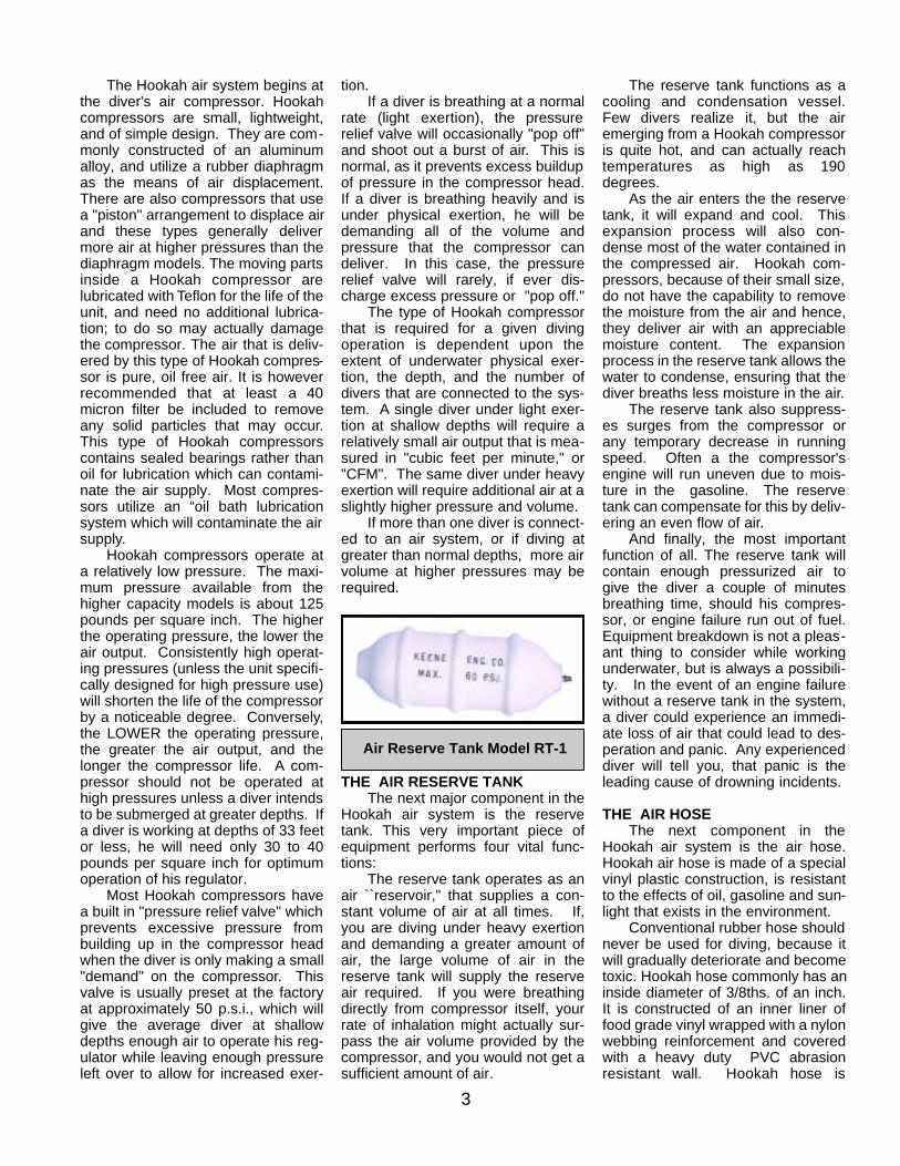
Air Reserve Tank Model RT-1

designed to prevent kinking and col-lapsing that could prevent the flow ofair being shut off
A quality Hookah hose will be col-ored a bright yellow or orange, for ahigh degree of visibility. It will alsofloat, so that any excess hose notactually being used will float on thesurface, completely away from thed i v e r, reducing the possibility ofentanglements on the bottom. Forexample, if you are diving in ten feetof water but are using a thirty footlength of air hose, the excess twentyfeet will float on the surface, com-pletely away from you.
A quality Hookah air will notimpart any "flavoring" to the air, andshould meet “F D A and OSHA”requirements.
THE REGULATORThe regulator is an oral respira-
tion device that is worn in the diversmouth. The regulator regulates theamount of air that is received by thediver each time he inhales. Becausethe divers nose is covered by his facemask, air must be inhaled through thedivers mouth .
There are two types of diving reg-ulators, those designed for SCUBAuse and those designed for Hookahapplications. A SCUBA regulator isdesigned for use with SCUBA a airtank, and delivers maximum efficien-cy when operated at a pressureexceeding 100 p.s.i. They require a"first stage" valve assembly, attachedto the SCUBA tank. The function ofthe first stage is to reduce theextremely high pressure of the air inthe SCUBA tank from approximately2,250 p.s.i. to approximately 180p.s.i. This pressure then goes to the
"second stage," which is the part thatis worn in the diver's mouth. The sec-ond stage of a SCUBA regulator hasa spring loaded "downstream" valvewhich delivers the correct amount ofair to the diver when driven by an airpressure ranging from 100 to 250p.s.i.
A prospective Hookah diver mustrealize that SCUBA regulators CAN-NOT be used for Hookah applicationswithout special modifications. A typi-cal Hookah compressor operates inan average pressure range of 30 to50 p.s.i., which is not enough pres-sure to drive the spring loaded down-stream valve of a SCUBA regulator.A diver who already owns a SCUBAregulator, but who wishes to use it forHookah applications, must take hisregulator to a competent dive shop orrepair station and get the regulatorconverted over for low pressure use;he should not attempt to do it himself.The conversion can be made byinstalling a set of low tension springswhich will give maximum efficiencywhen operated at low Hookah pres-sures. A dive shop or repair stationwill also have the necessary testgauges, etc., to make certain theadaptation has been effective.
A Hookah regulator is entirely dif-ferent from a SCUBA regulator. Itconsists of a "second stage" only,which is fed directly from the output ofthe reserve tank via the air hose.There are no valve assemblies of thetype that are used with SCUBA tanks.Hookah regulators employ a "tilt," or
"pin" valve, which delivers a full airflow to the diver at a pressure as lowas 30 p.s.i. This type of regulator isspecifically designed for use with lowpressure Hookah compressors.Hookah regulators, as are all modernregulators, are of the single hose,"demand" type. A "demand" regulatorworks on a relatively low volume ofair, since it only has to deliver air asthe diver breathes, or "demands" it..
THE HARNESSA regulator should not be used forHookah diving unless it is in conjunc-tion with a "chest harness." The har-ness serves two principle functions:
1. It keeps the air hose from gettingin the diver's way when he is workingu n d e r w a t e r. The harness has a"back plate" which is automaticallypositioned over the center of thediver's back when the harness isSince the air hose terminates at thediver's back, it prevents potentialentanglements around the diver'sbody.
4
Typical air system for one diver, including air hose, reserve tank,regulator, harness, and connector hose to compressor
Typical Hookah Air Regulator and Harness

2. The regulator intake hose thatattaches to the check valve preventsany pulling motion from the regulatorwhile working underwater. For exam-ple; if a diver were moving aroundunderwater and inadvertently cameto the end of the air hose, the harnesswould absorb the shock and the reg-ulator and would not be jerked fromthe diver's mouth.
INCIDENTAL ACCESSORIES,HOSES, HINTS, PRECAUTIONS:
One accessory hose item you willneed is a short length of hose forrouting the air output from the com-pressor to the input of the reservetank. The type of hose that is need-ed depends upon the compressoryou are using. Diaphragm modelsthat operate in the 30 to 50 p.s.i.range use a simple hose connectorthat is made of hookah air hose. The high pressure, high volume pis-ton compressors that are capable ofdelivering pressure of 100 p.s.i.,require a connector made of specialcertified "heat resistant steam" hose,due to the fact that these models dis-charge air at higher temperatures.
When setting up a Hookah airsystem, you will frequently need anarray of metal fittings. For usearound water, you should use stain-less steel or brass fittings only. Thisis especially important when diving insalt water.
Fittings made of ferrous metal willrust or corrode when used in, or neara water environment.
If your Hookah compressor ispowered by a gasoline engine, makeevery effort to ensure that the engineexhaust (which contains deadly car-bon monoxide gas), is always placedDOWNWIND from the compressor.This will help prevent exhaust frombeing accidentally pulled into thecompressor's air inlet. Always use a“snorkel” extension on any compres-sor that can elevate the intake of theair supply away from engine exhaustcontaminates.
Never use a gasoline poweredcompressor in confined areas, suchas underneath piers, in close, narrowgrottos, etc. This will prevent theexhaust gases from dissipating intothe atmosphere safely. Also, neverdive in an area where there is littleventilation or air movement. Take
special precautions when diving inareas where the air is extremely still,as dead air spaces, or poor ventila-tion can cause exhaust gases tolinger in the immediate area of theengine and compressor unit.
Always install a long extensionon the intake of your compressor toavoid the possibility of contaminationof Carbon Monoxide Gas from theengine exhaust system. The airintake of a compressor must towerover the engine exhaust at a suffi-cient height or distance to avoidintake of engine exhaust gas. If thisgas is inhaled even in small quantitiesfor short periods, it can cause severeheadaches and possibly result insickness. In larger quantities it cankill you, so please be careful!
If you are using Hookah equip-ment around salt water, be sure torinse off all your components withfreshwater afterwards. This includesyour regulator, diving mask, harness,metal fittings, and air hose (flush itout on the inside as well as outside).A salt water environment will quicklycorrode aluminum parts such as:Hookah compressors and gasolineengines. It is advisable to keep allmetal components freshly paintedand cleaned to avoid excess corro-sion.
If you are using a gasoline pow-ered compressor always shut of theengine before attempting to refuel.Do not attempt to refill the engine'sgas tank while the engine is still run-ning, as this will increase the possibil-ity of spilling gasoline onto a hotengine, which could result in a poten-tial fire or cause an explosion.
A diver should always surfaceand shut off the engine first prior torefueling and allow time for theengine to cool down. Always use afunnel for refilling the gas tank, or aspecial spillproof gas container toprevent spillage.
Every Hookah diver shouldunderstand the basic rudiments ofengine and compressor mainte-nance, and should always keep hisequipment in top condition. If youtake proper care of your equipment, itwill give you many years of troublefree service. Knowing how to work onyour own equipment will also come inhandy, should you experience anymechanical failure on a diving trip. Itis a good idea to carry
along some spare parts for your aircompressor, and the necessary toolsto make repairs.
All of the basic "rules of the deep"that apply to SCUBAdiving also applyto Hookah diving as well.
UNDER NO CIRCUMSTA N C E SSHOULD YOU DIVE ALONE.! Always Hookah dive with a partnerwho owns his own regulator, harness,and air hose.
Make sure that his or her equip-ment as well as yours is attached tothe air system at all times. If youwere to experience underwater prob-lems, your "diving partner" should beavailable to come to your immediateassistance.
Even though no formal instruc-tion is required to use Hookahequipment, we strongly recom-mend that all divers should take a “CERTIFIED SCUBA” course atyour local county or diving supplystore.
You should also read books onthe subject of underwater diving safe-ty and study them thoroughly. Thiswill further familiarize you with the"rules of the deep."
5
New 12volt system HAS


6
WARNING CARBON MONOXIDE GASIf you're considering diving with a "Hookah Compressor" , It is most important that you become aware ofPotential Danger associated with exhaust emissions. We place a caution label on the engine, warning of dan-gerous engine fumes and also illustrate further warning in " Introduction to Hookah Diving" and Safety inGold Dredging that is issued with the purchase of all diving equipment.
WHAT IS CARBON MONOXIDE GAS?Carbon Monoxide is an invisible odorless gas which gives no warning of its presence. It is the product ofthe incomplete burning of any material such as ; Oil Gasoline, Wood, Coal, etc. that contains carbon.
WHAT IS THE EFFECT OF CARBON MONOXIDE EXPOSURE?Carbon Monoxide deprives the blood of its ability to carry oxygen throughout the body. When CarbonMonoxide is inhaled , it chemically combines with hemoglobin, the oxygen carrier in the blood. Even ifthere is plenty of oxygen in the air, hemoglobin combines much more readily with Carbon Monoxide thanwith oxygen. As the oxygen level of the blood is reduced, the heart must pump faster in an effort to sup-ply sufficient amounts of oxygen to the brain and other parts of the body. When the brain does not receiveenough oxygen, symptoms of headache, dizziness and mental confusion occur. Further exposure to the gascauses lack of coordination, weakness and nausea. The final effect of excessive exposure are convulsions,coma and death.
Needless to say, we cannot emphasize strongly enough that caution must be exercised. Never dive alone,never dive in an enclosed area, or in an area where good ventilation is not eminent such as; under piers, nar-row grottos, under heavily overgrown brush or trees or in any area where a good breeze does not occur.Always make an effort to position your air unit to allow the prevailing breeze to carry any exhaust emissionsaway from the air intake of the compressor.
Remember, Carbon Monoxide is the product of incomplete burning of gasoline and oil, so it most importantto keep your unit properly running and clean. Never allow gasoline to overfill or spill anywhere near engineand compressor.
THE SAFETY AIR SNORKEL DOES NOT ELIMINATE CARBON MONOXIDE GAS, IT ONLY AIDSIN THE REDUCTION OF FUMES. ALL THE SAFETY CAUTIONS MUST BE OBSERVED !
REMOVE AIR FILTER FROM THEAIR COMPRESSOR AND INSTALLIN THE TOP OF THE AIR SNORKEL
SNAP FIT
SNORKEL SLIDES INSIDE THE COMPRESSOR INTAKE
1/4-20 X 2"
#10-24 X 2.5"
SPACER
BOLT
BOLT
STABILIZING BRACKET
1/4" NYLON NUTAND WASHER
#10-24 X 1/5
PHILLIP PAN HEAD
#10 NUTS
ALUMINUM
ALUMINUM SNORKELSUPPORTS

7
A5C
263/265 COMPRESSOR TANK CONFIGURATION2 OR 3 DIVERS (RT 9 OR RT 25)
RT9S AND RT25S STAINLESS STEEL TANK
1/4" M BRASS PETCOCKALLOWS DRAINAGE OF THE CONDENSATION FROM THE
RESERVE TANK
A5C
1/4 F X 1/2M
A5C
HC1STA2
THIS IS THE AIR SUPPLYCOMING FROM THE H.P.COMPRESSOR
A4
A8
A8
A8
A5C
A5C
1/4 F X 1/2M
A5E
A5G
A5F
TOAIR
LINES
High temperature hose (HC1ST) must be usedon the out put of the 263 Air Compressors
The 263 Compressors run Hot and can Heat up standard air hose on blow the ends off.
A4
A5E
A5G A8
A8
TOAIR
LINES1/4 F X 1/2M
Optional Recommended Air filter (CDAF)
CDAFAir intakes are re-located to reduce the chance of Carbon Monoxide intake
263G & 263GH
Remote air intakes reduce the chance of
Carbon Monoxide Poisoning

KEENE ENGINEERINGKEENE ENGINEERING20201 Bahama Street Chatsworth California 91311
Tel. (818)-993-0411 Fax. (818)-993-0447E-mail: [email protected]
Web site www.keeneengineering.com
INSTALLATION & REPLACEMENT OF A PUMP SEAL, MARLEX PUMPCOUPLER & A COMPRESSOR DRIVE ASSEMBLY
The water pump seal must be replaced if water is observed leaking between the engine and pumpadapter or around the engine shaft,. To replace a seal or to install a compressor drive assembly (engineshaft pulley and drive belt), the pump must first be removed from the engine.
INSTRUCTIONS TO REMOVE THE PUMP FROM THE ENGINE:Note: If the pump has been in use for a year or more, we suggest that you apply a penetrant such as"WD-40" to the engine shaft threads and allow it to penetrate the threads of the engine shaft. Saturate for24 hours before attempting to remove the impeller from the engine shaft!1. Remove the four housing bolts and remove the pump housing. If the housing does not pull off easily,gently pry it off with a screwdriver. Inspect the housing gasket and replace if necessary.2. The impeller is directly mounted to the engine shaft and will unscrew in a counter clockwise direction.Before attempting to remove the impeller the engine shaft must be locked in a fixed position to preventit from turning. A simple way of locking the shaft is to insert a pointed tool such as a screwdriver or an awlthrough one of the many holes in the starter assembly and turning the engine over until the tool is firmlylocked in place by the starter housing cover.IMPORTANT: Always disconnect the spark plug wire before attempting any repairs or service on yourpump or engine. Once the engine shaft is locked into position, there are two methods that can be usedto remove the impeller.Method #1. Use a block of wood, such as a 2x4 and place one corner of it into one of the impeller vaneson the left side of the impeller and strike the block of wood sharply with a hammer. This should loosenthe impeller and enable it to be unscrewed in a counter clock-wise direction.Method #2. If the above is not successful, use a thin breaker bar or a heavy duty screw driver. Insert theblade into one of the impeller vanes towards the left side and try to unscrew the impeller by applying adownward pressure. If this still does not work carefully strike the end of the bar with a hammer until theimpeller loosens from the shaft. If this still does not work, strike gently with a hammer. This method maycause a chip in the vane of the impeller. Depending on the size break of the corner of the impeller, it mayor may not have adverse effects on the performance of the pump. So be careful!
SEAL REMOVAL AND INSTALLATION:1. All of our pumps use a two piece seal assembly, with the exception of some older models (P-50and P-60). One half of the seal located in the backside of the impeller is called the "seat", or ceramicportion. The other side of the seal is shrouded in a brass encasement, encasing a hardened material thatrests against the ceramic portion of the seal. Always replace both sides of the seal. Remove the ceramicportion with a sharp object similar to a screwdriver and press the new seat into place by hand. Alwaysinspect the seal to note that it is not cracked. Always place the smooth surface of the seal to the outside.

2. Remove the pump adapter from the engine and press the brass portion of the seal towards theoutside from the back of the adapter. If it cannot be pressed out easily, place a screwdriver handle onthe seal and gently tap it out. When replacing, it is suggested that a small amount of silicone sealant beplaced on the brass portion that fits into the adapter to ensure that it will not leak. Be careful not to get anysealant on the face of the seal. Position the seal in the center of the hole and press gently by hand intothe cavity as far as possible. Use a screwdriver or a blunt instrument and tap the seal gently around theedge of the seal in a circular motion until the seal is firmly fitted into place. Wipe off seal facing with a cleancloth before reassembling.3. After both sides of the seals is installed, replace the pump adapter onto the engine and carefullytighten. Thread the impeller onto the engine shaft until the impeller is hand tight. Install the housing anduse care not to over tighten the bolts to avoid stripping the threads as they are a soft alloy aluminum.
HOW TO INSTALL THE HOSE ADAPTOR PUMP INTAKE COUPLER: (For all models except theP-50 and P-300 Series).The tolerance of the Hose Adapter is critical for proper pump performance. The hose Adapter shouldbe installed as close as possible to the intake portion of the impeller. Center the adapter into the housingopening and press in by hand to locate it into place and place a wooden block against the outside of theadapter and gently tap until the adapter is firmly seated against the face of the impeller. Pull the starterrope until the engine turns. When the coupler is properly seated, the engine should be somewhatdifficult to turn over, making sure that the adapter is against the face of the impeller.
COMPRESSOR DRIVE INSTALLATION:To install the shaft pulley and belt for a compressor adaptation, the pump must be completely removedfrom the engine. For larger engines to include the 8 HP through 18 HP engines, slide the pulley to theback of the engine shaft and tighten the set screw. To install the engine pulley on smaller engines toinclude the 3HP to 5HP Engines, the furnished bushing should be pressed onto the pulley at the factoryto ensure proper alignment and spacing. If you choose to install it yourself, this can be accomplished byplacing the pulley on a flat surface, center the bushing in the hole of the pulley and gently drive it throughby tapping it with a hammer taking care not to damage the bushing. The bushing should be pressed ordriven through the pulley, in a flush position to the other side of the pulley. It should not extend thoughthe other side. Then install the V Belt before placing the pulley and bushing over the engine shaft. Afterthe pump is installed and secured, mount the compressor and compressor pulley. Install the V Belt tocompressor and make sure that the alignment is correct. You can compensate for some misalignment byadjusting the compressor pulley on the compressor shaft. Tighten firmly the set screw and all bolt andcheck for any misalignment before starting.

GENERAL OPERATING INSTRUCTIONS
THE FOLLOWING INFORMATION SHOULD ENABLE YOU TO UNDERSTAND THE BASIC THEORY OF OPERATION OF A PORTABLE DREDGE.
For more complete understanding on this subject, we recommend you read any one of a variety of books availablethrough the Keene Library of Books, such as The Gold Miners Handbook, Dredging for Gold or Advanced DredgingTechniques. The vacuum on a portable dredge is created by a "venturi principal". A volume of water is pumped througha tapered orifice (jet), by a special designed water pump. A high velocity jet stream is created within the jet tube produc-ing a powerful vacuum. As indicated in the diagram gravel is dredged into the suction hose and is delivered to the sluicejet flare. As a slurry of water and gravel enters the jet flare and is spread evenly over a classifier screen. The smaller andheavier particles drop below the classifier screen into an area of less velocity, allowing a slower and more selective clas-sification of values. Often values are recovered and easily observed before they even enter the riffle section. The lighternon bearing values and larger aggregate are returned back into the water. The riffles, or gold traps in the sluice box arebest described as "Hungarian Riffles". This type of riffle has proven to be the most efficient gold recovery system. Asmaterial flows over the riffles, a vortex, or eddy current is formed between each riffle opening. This force allows the heav-ier material to settle out of suspension and the lighter, non value bearing material to be washed away. This continuousself cleaning principal allows a dredge to be operated for prolonged periods of time. Normal conditions require a sluicebox to be cleaned only once or twice a day. PRIMING THE PUMPBefore starting the engine, the pump must be fully primed. This means the pump must be full of water and all airremoved. All jetting pumps provided with our dredges have a mechanical water pump seal. Without the presence ofwater in the pump, friction could cause a seal to overheat and require replacement. Priming the pump on some of thesmaller models is accomplished by thrusting the foot valve back and forth under the surface of the water in a reciprocat-ing motion. This will pump water into the foot valve assembly and into the pump. A pump is fully primed when water isobserved flowing out of the discharge end of the pump. It may sometimes become necessary to hold the dischargehose above the level of the pump to complete the priming operation. The larger dredges that have a rigid foot valve, areeasily primed by removing the cap provided on the foot valve and filling, until water overflows. Caution must be exercisedto prevent sand from entering the foot valve or intake portion of the pump. Excess amounts of sand could damage thewater pump seal, or pump impeller. It is recommended that the intake portion of the foot valve be placed in a sand freeenvironment underwater, such as a small bucket or pan. PRIMING THE SUCTION HOSEPriming the suction hose need not be of concern in most dredging operations, but is important to understand the princi-pal. When the tip of the suction hose is taken out of the water during operation air will enter the suction system andcause the suction power to cease temporarily, until submerged again. The suction will commence as soon as the air haspassed through the system. It is important to ensure that no air leaks occur in the suction system. SUCTION SYSTEM OBSTRUCTIONSThe suction system can become jammed while dredging. This can be caused by dredging an excess of sand, causingthe suction hose to load up, or a rock that has become stuck in the suction system. Rock jams generally occur in the jet,or just before entry into the jet. This can easily be cleared by removed by flipping the rubber damper back over the jetflare and thrusting the probe rod down through the jet flare and jet in an effort to strike the obstructed area. It may occa-sionally be necessary to remove the suction hose to remove an obstruction. If this is not successful. it may be necessaryto locate the blockage in the transparent hose and dislodge it by a striking the obstruction, taking care not to damage thehose. SOLID CONTENTCare must be exercised to prevent dredging excess amounts of sand. A solid to water balance must be maintained. Thesolid content being dredged should never exceed 10%. If a suction tip is buried in the sand and not metered properly thesolid content could cause the suction hose to become overloaded with solids and suction will cease, this will also causethe sluice box to become overloaded with solid content, resulting in a loss of values.SLUICE BOX ADJUSTMENTMost models have a slight adjustment to raise or lower the sluice box. The proper sluice box adjustment can effect therecovery of values. If the sluice does not have enough angle, the sluice box will "load up" causing the riffle openings tofill with unwanted excess material. Too much angle will cause the material to flow too fast, resulting in loss of values, evi-denced by the riffles running too clean. The optimum adjustment of a properly working sluice box is evident by only aportion of the riffle is visible while operating. A loss of values can also occur if the solid content of the suction discharge istoo heavy in solid content. Remember, the solid content should not exceed 10 %. A normal sluice box tilt is approximate-ly 3/4” inch to the running foot. Afour foot sluice box should have an approximate tilt of 3" CLEANING THE SLUICE BOXBefore attempting to clean the sluice box, it should be allowed to run with only water for a few minutes in order to wash

out any excess gravels that have accumulated. Either turn engine off, or let run with a slow idle, then remove the classifi-er screen and replace the wing nut to prevent losing it. Unsnap the riffle latches, fold the riffle tray up, and let rest againstthe jet flare, taking care not to let it drop back into place while cleaning. This could result in a potential injury! Place awide tray, bucket or large gold pan at the end of the sluice, then carefully roll up the riffle matting and wash into the con-tainer at the end of the sluice. Rinse any excess gravel that remains in the sluice into container. All material must beremoved before replacing the riffle matting, riffle tray and classifier screen. ENGINE SPEEDMost small engines are throttle controlled. The speed of the engine can be controlled with the use of a lever. Althoughthe rated horsepower is achieved on most small engines at 3600 R.P.M., it may not be necessary to operate the dredgeat full speed. Lower speeds conserve engine life and fuel economy. Be sure to read all instructions and especially theengine instructions that are provided with each unit. ENGINES ARE NOT SHIPPED FROM THE FACTORY CONTAIN-ING OIL. OIL MUST ADDED PRIOR TO USE! ENGINES OPERATED WITHOUT SUFFICIENT OIL S U P P LY W I L LINVALIDATE ENGINE WARRANTEE!
TROUBLE SHOOTING
[A] IF SUCTION DECLINES 1. Check the suction device for an obstruction. An obstruction can be removed by probing the obstructed area with theprovided probe rod. I may be necessary to check the suction hose for a visible obstruction. This can be remedied byeither back flushing the system or dislodging the obstruction with a gentle blow. 2. Check the pump for loss of prime or blockage. The foot valve may be too close to the surface of the water and air mayenter the intake of the pump via a small whirlpool. The pump intake or foot valve screen may be plugged with leaves ormoss, restricting flow into the intake of the pump. Check and tighten all clamps to prevent an air leak.
[B] IF PRIMING THE PUMP BECOMES DIFFICULT1. Check all clamps for an air leak. 2. It may be necessary to check the foot valve for a small leak. This is accomplished by removing the foot valve assem-bly from the pump and blowing air into the hose portion of the assembly and listening for an air escape. It may be nec-essary to remove the hose and check the rubber valve for an evidence of a leak, or for a small obstruction preventing thevalve from sealing. 3. If a water pump seal is either defective or damaged, a leak will be evident on the inside portion of the pump aroundthe drive shaft. Often a new pump will leak slightly, until the seal and gasket has become fully seated. This is a commonoccurrence in most new pumps.
PUMP
SUCTIONNOZZLE
SUCTION HOSE
POWER JET
RIFFLES
SLUICE BOX
FOOT VALVE
INTAKE HOSE
PRESSUREHOSE

12356 1410
49
11
1213
8
7
14
10VW11VW 12VW35
412139VW
6VW 16VW
7
8VW
15VW
ISOLATOR PLATE BOLTS DIRECTLY TO VW FLYWHEEL
14VW
P1500 PUMP ASSEMBLY AND PARTS
Be sure to remove # 13 zerk discharge plug when greasing the pump or you will blow out the outer bearing caps and thisWill destroy the pump bearings

KEENE ENGINEERINGSTORM DICKINSON
JUNE1994
P1500 PARTS LIST
ITEM NO. PART DESCRIPTION PART NO. QTY.1 HOUSING 1500H 12 PEDESTAL IMPELLAR 6 5/8" 1500IP 1
2VW VW IMPELLAR 6 3/8" 15001VW 13 IMPELLAR SPACER 1500IS 14 PUMP SEAL WPS5 15 "O" RING GASKET 1500OR 16 PEDESTAL MOUNT 1500P 1
6VW VW BELL HOUSING 1500BH 17 GARDEN HOSE ADAPTER 1500GHA 18 RUBBER SLINGER 1500RS 1
8VW RUBBER SLINGER 1500VWRS 19 PEDISTAL BEARINGS 1500PB 2
9VW VW BEARINGS 1500VW 210 PEDISTAL BEARING SPACER 1500PBS 1
10VW VW BEARING SPACER 1500VWBS 111 PEDISTAL SHAFT 1500PS 1
11VW VW SHAFT 1500VWS 112 ZERK INPUT FITTING 1500ZI 113 ZERK DISCHARGE PLUG 5/16"X18 1500ZD 114 PDEISTAL HOUSING BOLTS 1 1/2"X1/2"X13 1500PHB 4
14VW VW HOUSING BOLTS 2 3/4"X1/2"X13 1500VWHB 415VW BELL HOUSING TO ENGINE BOLTS 10mmx7mm 1500VWBHEB 216VW NUTS FOR STUDS ON ENGINE 1500VWNS 217VW PUMP ADAPTER 1500PA 1