generation and acceleration of low-emittance, high...
TRANSCRIPT

Generation and Acceleration of Low-Emittance, High-Current
Electron Beams for SuperKEKB
M. Yoshida, N. Iida, S. Kazama, T. Natsui, Y. Ogawa, S. Ohsawa, H. Sugimoto, L. Zang, X. Zhou,
High Energy Accelerator Research Organization D. Sato, Tokyo Institute of Technology

KEKB obtained
(e+ / e-) SuperKEKB required
(e+ / e-)
Energy 3.5 GeV / 8.0 GeV 4.0 GeV / 7.0 GeV
Charge e- e+ / e-
10 1.0 nC / 1.0 nC e- e+ / e-
10 4.0 nC / 5.0 nC
Emittance [mm-mrad]
2100 / 300 6 / 20
e-
e+J-linac
HER
7 GeVLER
4 GeV
SuperKEKB
AR
6.5 GeV
PF
2.5~3.0 GeV
A-1 RF gun
3-2 RF gun
A sectorB sector
C sector 1 sector 2 sector 3 sector 4 sector 5 sector
J arc
SuperKEKB Upgrade and RF gun development
5 nC 10 mm-mrad electron beam generated by RF gun.
+ 10mm-mrad emittance preservation is required.
Preliminary test using DAW
RF-Gun with Nd laser system
due to earthquake. (2011)
Quasi –travelling side couple
RF-Gun with Yb laser system.
(2013)

RF-Gun development strategy for SuperKEKB
• Cavity : Strong electric field focusing structure – Disk And Washer (DAW) => 3-2, A-1(test)
– Quasi Traveling Wave Side Couple => A-1
=> Reduce beam divergence and projected emittance dilution
• Cathode : Long term stable cathode – Middle QE (QE=10-4~10-3 @266nm)
– Solid material (no thin film) => Metal composite cathode
=> Started from LaB6 (short life time) => Ir5Ce has very long life time and QE>10-4 @266nm
• Laser : Stable laser with temporal manipulation – LD pumped laser medium => Nd / Yb doped
– Temporal manipulation => Yb doped => Minimum energy spread

• RF-Gun
– Design of RF-Gun cavity
• Quasi travelling wave side couple
– Cathode
– Laser
– Test stand and schedule

RF-Gun for 5 nC
• Space charge is dominant.
– Longer pulse length : 20 - 30 ps
• Stable operation is required.
– Lower electric field : < 120MV/m
• Focusing field must be required.
– Solenoid focus causes the emittance growth.
– Electric field focus preserve the emittance.
0
2
4
6
8
10
12
14
16
18
20
0 10 20 30 40 50
Tlaser (ps)
Em
itta
nce (
mm
mra
d)
emittance(RF)_x@5nC&90MV/m
emittance(SC)_x@5nC&90MV/m
emittance(total)_x@5nC&90MV/m
Total
Space charge RF
Epxial coupled cavity : BNL
Annular coupled cavity : Disk and washer
or Side couple

Concentrated field
has focusing effect
This structure
has long drift
space
Closed gap makes focus field
Side coupled cavity is one candidate (or DAW / ACS / CDS …)
This structure has focusing field.
Long drift space is problem.
加速電場
ビーム
Accelerating field
Beam
Electric focusing field by narrow gap

Normal side couple structure Quasi traveling wave sidecouple structure
Design of a quasi traveling wave side couple RF gun
Quasi traveling wave side couple has stronger focusing field

Emittance: 5.5 mm-mrad @ 5 nC
This RF gun can generate 10 nC beam
Quasi traveling wave side couple RF gun This RF gun has total of seven acceleration cavities. These are divided into two standing wave structure of 3 and 4 side coupled cavities respectively.
Maximum E-field at surface: 100 MV/m Maximum E-field at surface: 120 MV/m
Cathode cell
To avoid beam defocusing, emittance
growth and field concentration, a lot of
parameters were searched for design.
cathode
0 100 200 300 400 500 600 700 800 900 1000
GPT z
0
1
2
3
4
5
rxy

Beam tracking simulation result
time=2.48098e-009
728 729 730 731 732 733
GPT z
11.3
11.4
11.5
11.6
11.7
Energ
y [M
eV
]
Emittance 5.5 mm-mrad
Size 0.4 mm
Energy spread 0.6%
Bunch shape
Gun Exit
5 nC 10 nC

RF-Gun comparison
DAW-type RF gun
(90 MV/m, 5 mm-mrad, 3.2 MeV)
BNL-type RF gun
(120 MV/m, 11.0 mm-mrad, 5.5 MeV)
Quasi traveling wave side couple RF gun
(100 MV/m, 6mm-mrad, 13.5 MeV)
BNL (3.8 mm)
QTW (0.2
mm)
DAW (1.7 mm)
Beam Size

coupling cavities accelerating cavity
cathode
Cavity design
beam
Field calculation
No reflection to klystron
0 24 2
2.7
2.8
2.9
3.0
3.1
0 24 2
Phase shift cell radF
requ
ency
GH
z k : 3.0 %
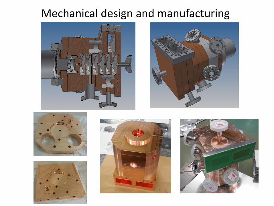
Mechanical design and manufacturing

• RF-Gun
– Design of RF-Gun cavity
– Cathode
• Advantage of LaB6
• Measurement equipment of quantum efficiency
• Laser cleaning & Heat treatment
– Laser
– Test stand and schedule

Cathode : Advantage of LaB6 or Ir5Ce
Justin Jimenez, A Systematic Cathode Study , Ph.D Thesis, Monterery, California
Physica Scripta. Vol. T71, 39-45,
1997.
Cathodes for Electron Guns
G. I. Kuznetsov
• Low Workfunction (2.8 eV) and enough QE (10-4) at room temperature.
• Inactive in air
• Recover by heating or laser cleaning
Best choice
for SuperKEKB 5 nC
long time operation
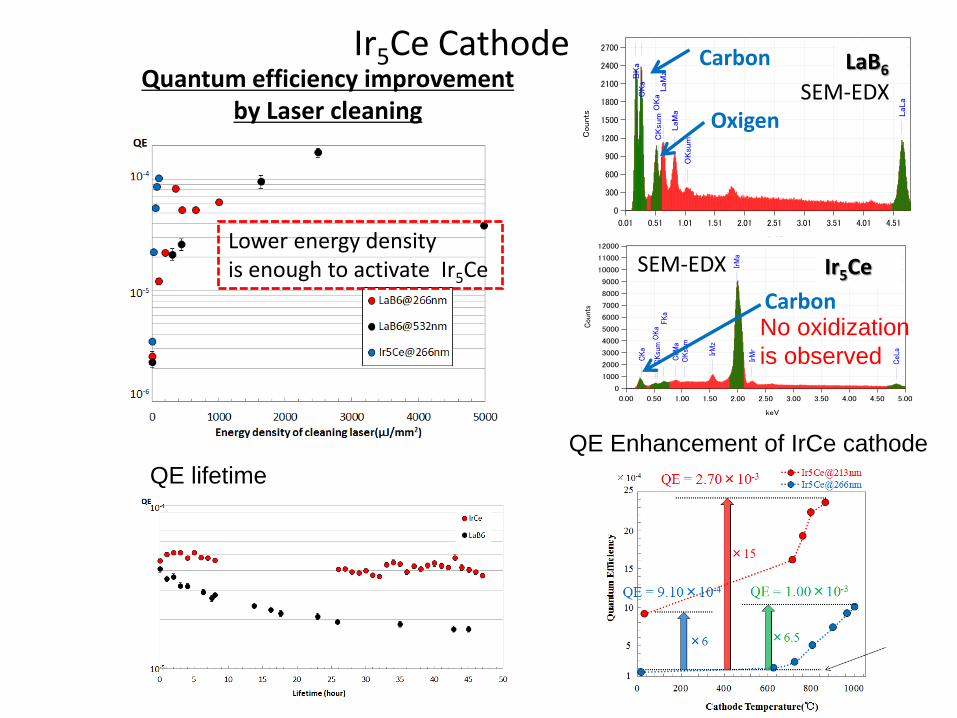
Quantum efficiency improvement by Laser cleaning
×20
Ir5Ce Cathode
0.01 0.51 1.01 1.51 2.01 2.51 3.01 3.51 4.01 4.51
keV
0
300
600
900
1200
1500
1800
2100
2400
2700
Counts
BKa
CKa
CKsu
mO
Ka
OKsu
m
LaM
z
LaM
a LaLa
LaB6 Carbon
Oxigen SEM-EDX
0.00 0.50 1.00 1.50 2.00 2.50 3.00 3.50 4.00 4.50 5.00
keV
0
1000
2000
3000
4000
5000
6000
7000
8000
9000
10000
11000
12000
Cou
nts
CKa
CKsu
mO
Ka
OKsu
m
FKa
CeM
a
CeL
aIrM
z
IrM
a
IrM
r
Ir5Ce
Carbon
SEM-EDX
No oxidization
is observed
Lower energy density is enough to activate Ir5Ce
QE lifetime
QE Enhancement of IrCe cathode

• RF-Gun
– Design of RF-Gun cavity
– Cathode
– Yb Laser for spatial & temporal manipulation.
– Test stand and schedule

Energy spread reduction using temporal manipulation
0
0.5
1
1.5
2
2.5
3
0 5 10 15 20 25 30
FWHM (ps)
σE/E (%)
Gaussian
Square
5nC 10nC
15nC
20nC
20nC 15nC 10nC
5nC
5nC electron 15nC
Primary beam for positron production
t
t
Energy spread of 0.1% is required for SuperKEKB synchrotron injection.

Properties of laser medium
LD Pump (808nm)
Nd:YVO4
Nd:YAG
SHG(532nm)
40%
FHG(266nm)
20%
5HG(213nm)
3%
τ~200μs, 40% Nd-doped
Yb-doped
Ti-doped
LD Pump (941/976nm)
Yb-glass
Yb:YAG
Yb:BOYS
1064nm 808nm
941/976nm 1040nm
τ~900μs, 40%
Pump
(808nm) Nd:YA
G
SHG
40%
1064nm 808nm
Ti:Sapphire
532nm 800nm
τ~3μs, 40% τ=200μs, 40%
○ 4-state laser is easy to operate.
○ High power pump LD is available.
○ Large crystal is available
× Pulse width is determined by SESAM.
(Gaussian)
○ Wide bandwidth => pulse shaping
○ Long fluorescent time => High power
○ Fiber laser oscillator => Stable
○ Small state difference
× ASE
× Absorption
○ Very wide bandwidth
○ High breakdown threshold
× Low cross section
× Short fluorescent time => Q-switched laser is required for pumping
Pump
TW laser is based on Ti-Sapphire
SHG(520nm) 40%
FHG(260nm) 20%
5HG(208nm) 3%
SHG(400nm) 40%
THG(266nm) 20%
FHG(200nm) 10%
Best for RF-Gun
Nd laser system for 3-2 RF-Gun
Ti:Sapphire laser system.
Material Nd:YAG Yb:YAG Ti:Sapphire
Wavelength 1064nm 1030nm 660-1100nm
Fluorescent time 230ms 960ms 3.2ms
Spectral width 0.67nm 9.5nm 440nm
Fourier minimumPulse width
2.48ps 165fs 2.59fs
Wavelength 807.5nm 941nm 488nm
Spectral width 1.5nm 21nm 200nm
Quantum efficiency 76% 91% 55%
Flu
ore
scence
Abs
orp
tion

Yb fiber & thin disk hybrid laser system
QE = 10-4 A few mJ @ 258nm, 50Hz is required.
258 nm 515 nm

Yb Fiber Laser
Yb Fiber
←
←
WDM LD
Transmission
grating pair

Thin-disk multi-pass amplifier
• 0.5 mmt Yb:YAG thin-disk
• 3-stage 4-6 multi-pass amplifier
1 2
3 4
5 6
Yb:YAG
LD LD
SHG+FHG A few mJ @ 258nm

• RF-Gun
– Design of RF-Gun cavity
– Cathode
– Laser
– Test stand and schedule
• 3-2 RF-Gun for preliminary test & PF injection
• A-1 RF-Gun

A-1 RF gun
- Quasi-travelling wave side couple RF-Gun
- Yb based laser system
Existing DC-Gun & pre-buncher Installed RF-Gun
Chicane for bunch compression
30ps => 10ps

Installed RF gun
Cathode
Laser port

A1 sector at KEK linac
x y
32.7 ±3.1 mm-mrad 10.7 ±1.4 mm-mrad
Q-scan emittance measurement beam size measurement for Q-scan
RF gun
A-1 RF gun results 5.6 nC bunch charge
was observed.

Emittance preservation

Emittance preservation
J-ARC R56 Emittance growth after 500 m Initial offset

Hardware for emittance preservation • Alignment
– Continuous monitor (HLS, Wire) + Active mover
– Beam based alignment (Higher mode measurement)
• Temporal manipulation
– Laser pulse shaping
– Bunch compression
• Beam diagnostics for offset injection
– RF Deflector
Developed by SLAC

BPM
Accelerating structure
Magic T
90 deg
Hybrid IQ
DBM
Synchronized RF
8~12 GHz
(Base RF: 10.38
MHz)
Dipole mode
Preliminary test for higher order transverse wakefield
from accelerating structure.
TM12 : 8.728 GHz

Summary • RF-Gun cavity
– Quasi travelling wave side couple structure.
• Cathode – Room temperature Ir5Ce cathode has enough QE. – Laser cleaning & laser injection angle is effective. – R&D for the QE improvement.
• Laser & control – Yb based laser system : A-1 RF-Gun
• Yb-fiber : Precise RF synchronization. • Yb-disk amplifier: High power output. • Temporal manipulation Under experiment.
– Stability / Control: Improved but not enough.
• RF gun comissioning – 5.6 nC bunch charge was generated by this RF gun.
• Emittance Preservation – Alignment / Bunch compression / Monitor etc.