generation of electron airy beams - tau
TRANSCRIPT

LETTERdoi:10.1038/nature11840
Generation of electron Airy beamsNoa Voloch-Bloch1, Yossi Lereah1, Yigal Lilach1, Avraham Gover1 & Ady Arie1
Within the framework of quantum mechanics, a unique particlewave packet exists1 in the form of the Airy function2,3. Its counter-intuitive properties are revealed as it propagates in time or space:the quantum probability wave packet preserves its shape despitedispersion or diffraction and propagates along a parabolic caustictrajectory, even though no force is applied. This does not contra-dict Newton’s laws of motion, because the wave packet centroidpropagates along a straight line. Nearly 30 years later, this wavepacket, known as an accelerating Airy beam, was realized4 in theoptical domain; later it was generalized to an orthogonal and com-plete family of beams5 that propagate along parabolic trajectories,as well as to beams that propagate along arbitrary convex trajec-tories6. Here we report the experimental generation and obser-vation of the Airy beams of free electrons. These electron Airybeams were generated by diffraction of electrons through a nano-scale hologram7–9, which imprinted on the electrons’ wavefunctiona cubic phase modulation in the transverse plane. The highest-intensity lobes of the generated beams indeed followed parabolictrajectories. We directly observed a non-spreading electron wave-function that self-heals10, restoring its original shape after passingan obstacle. This holographic generation of electron Airy beamsopens up new avenues for steering electronic wave packets liketheir photonic counterparts, because the wave packets can beimprinted with arbitrary shapes5 or trajectories6.
Curved light is an intriguing caustic phenomenon2 common innature and in everyday life; examples range from rainbows3 to thebright light patterns that appear on the sea floor when sun shines onrippling water waves2. Caustics, already studied in the nineteenthcentury, led George Biddell Airy to discover the Airy function3.When the quantum mechanical probability density of a particle isimposed with the initial shape of an Airy function, the regions ofmaximum probability, that is, the intensity peaks of the Airy function,preserve their shape11 and stay localized around parabolic trajectoriesin space, similar to that of a freely propagating projectile experiencinga transverse accelerating force. As already pointed out, this accelerat-ing Airy wave packet1 does not contradict Ehrenfest’s theorem(embodying Newton’s second law of motion), as the wave packetcentroid travels along a straight path. The evolution of a light beamin space corresponds to the paraxial Helmholtz equation, which re-sembles the Schrodinger equation. This analogy led to the discoveryand the experimental realization of the optical Airy beams4. The intri-guing propagation dynamics of Airy beams is a caustic wave pheno-menon that can be understood by ray analysis: the wave packet iscomposed of a family of rays that coalesce along a curved boundary12.The local angular momentum of Airy beams changes as they propa-gate, but the total momentum and energy are conserved13. Variousapplications followed the discovery of optical Airy beams, includingmicroparticle manipulation14, generation of plasma channels in airand water15, surface Airy plasmons16–18 and applications in lasers19,20
and in nonlinear optics21. All of these rely on the Airy form of the wavepacket of photons.
The spatial evolution of the envelope, Y , of an electron’s wave-function can be expressed using the paraxial Helmholtz equation(Supplementary Information, section 1):
+2\z2ikB
LLz
� �Y~0
where +2\~L2=Lx2zL2=Ly2 is the transverse derivative and kB~
p=B~2p=lB is the de Broglie wavenumber of the electron (B,Planck’s constant divided by 2p). This equation has the same formas that of the Schrodinger equation. However, rather than describingthe time evolution of the electron’s wavefunction, it describes thewavefunction’s evolution as it propagates in space. This is anothermanifestation of the analogy, widely used in optics, between beamdiffraction in space and pulse dispersion in time. When the initialwavefunction of the electron is an Airy function (Ai), Y(x,y,z~0)~Ai(x=x0)Ai(y=y0), where x0 and y0 are characteristic length scales, thegeneral solution for the wave packet is1,10,14
Y(x,y,z)~Aixx0
{z2
4k2Bx4
0
� �Ai
yy0
{z2
4k2By4
0
� �
|exp ixz
2kBx30{i
z3
12k3Bx6
0
� �
|exp iyz
2kBy30{i
z3
12k3By6
0
� �ð1Þ
It is then clear from equation (1) that jY j2 preserves its shape andfollows a parabolic trajectory. The parabolic trajectory is described by22
x(z)~z2=4k2Bx3
0, y(z)~z2=4k2By3
0. The ideal Airy beam carries an infi-nite amount of energy, whereas in practice the Airy beam is truncated,having a finite energy. The finite Airy beam is obtained by multiplyingthe Airy function with an exponential or Gaussian window4. Never-theless, over a finite distance, the finite Airy beam has all the specialcharacteristics of the infinite Airy beam such as slow diffraction,curved trajectory and self-healing.
In optics, finite Airy beams were experimentally obtained by passinga Gaussian beam through a phase mask imprinting a cubic phasemodulation in the transverse direction4, and then doing an opticalFourier transform (the Fourier transform of a function having a cubicphase modulation results in an Airy function). Here we use electronsinstead of photons. These electrons pass through a hologram thatadds a transverse cubic phase, exp(iQ(x,y))~exp(icxx3)exp(icyy3), tothe wavefunction. Our hologram design method was to construct abinary diffraction grating with the following shape23,24:
h(x,y)~12
h0(sgnfcos½2px=Lzcxx3zcyy3�zDcyclegz1)
In this way, a cubic phase is imposed on a carrier frequency. The carrierperiod is L, h0 is the ridge height of the binary phase mask and Dcycle isan arbitrary duty cycle factor. When electrons (or light) diffract fromthe binary structure, it decomposes into different diffraction orders;the complex amplitude of the mth-order diffracted beam is propor-tional to exp(imw(x,y)). In the special case of a cubic phase modulation,each diffraction order is superimposed with a different cubic phase andso has an amplitude proportional to exp(im(cxx3zcyy3)). Each ordertherefore propagates along a different parabolic trajectory with a quad-ratic coefficient proportional to 1=m (Supplementary Information,
1Department of Physical Electronics, School of Electrical Engineering, Fleischman Faculty of Engineering, Tel Aviv University, Tel Aviv 69978, Israel.
2 1 F E B R U A R Y 2 0 1 3 | V O L 4 9 4 | N A T U R E | 3 3 1
Macmillan Publishers Limited. All rights reserved©2013
section 2). We name this diffraction pattern the ‘Airy lattice’ (Figs 1and 2). The general parametric equations of the trajectories of orderm are
xm(z)~{1m
14k2
Bx30
z2zmzGkB
zmfGkB
ym(z)~1m
14k2
By30
z2
ð2Þ
where G~2p=L is the reciprocal lattice vector of the transmissionhologram and f is the focal length of the lens. Note that the y trajec-tories include only a quadratic term, whereas the x trajectories containboth a quadratic term and a linear term, owing to the modulation of thecarrier frequency. The Airy lattice is a novel type of lattice that diffractsbut does not spread. Although each order diffracts in a different dir-ection, each order stays localized and anomalously bends.
In our experiment, we use a field-emission-gun transmission elec-tron microscope (FEG-TEM), operating at 200 keV. The de Brogliewavelength, including relativistic correction in this case, is approxi-mately 2.5 pm. Therefore, to generate the inner structure of Airy beamsas well as the spatial separation of different orders, we used nanoscaleholograms (Supplementary Information, section 3). The micrographsof these nanoscale holograms are shown in Fig. 3b, c. The Fouriertransform of the modulated wavefunction is done using a set of
magnetic lenses, so that an electron Airy beam is obtained in the backfocal plane of the FEG-TEM. This method is analogous to the methodused to generate optical Airy beams4, the only difference being that wemanipulate electrons rather than photons. Some of the results from theAiry profiles are shown in Fig. 3d and Fig. 3e. Because the measure-ment plane is located at a fixed position in our FEG-TEM, we variedthe focal lengths of the magnetic lenses to observe the formation andevolution of the electron Airy wave packet in space (Fig. 3a). Theexperiment details are given in Supplementary Information, section 4.
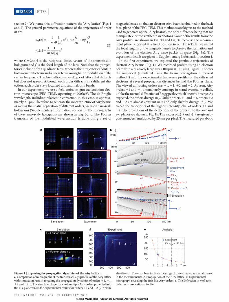
In the first experiment, we explored the parabolic trajectories ofelectron Airy beams (Fig. 1). We recorded profiles using an electronbeam with a relatively large area (100mm 3 100mm). Figure 1a showsthe numerical (simulated using the beam propagation numericalmethod21) and the experimental transverse profiles of the diffractedelectrons at several propagation distances behind the Fourier plane.The viewed diffracting orders are 11, 21, 12 and 22. As seen, Airyorders 11 and 21 anomalously converge in x and eventually collide,unlike the normal diffraction of Bragg peaks, which linearly diverge. Asexpected, the orders diverge in y. Unlike orders 11 and 21, orders 12and 22 are almost constant in x and only slightly diverge in y. Wetraced the trajectories of the highest intensity lobe, of orders 11 and12. The projections of the deflections of the orders into the x–z andy–z planes are shown in Fig. 1b. The values of x(z) and y(z) are given bypixel numbers, multiplied by 25mm per pixel. The measured parabolic
Δy
m
1
–1
–2
2
3
–3
Airy lattice
x
y
z
z
(m)
Experimentm = 1
Carrier m = 1x1 + y1Carrier m = 2x2 + y2
Experimentm = 2
Simulation
Fit x1 Fit x2
2(mm)
(mm)
1
–1
–1–1
–1–1
–1
Simulation
Simulation Experiment Analysisz = Fourier plane
z = Fourier plane + z′
Experiment
1
1
1
–2
–2–2
2
2
22
2
–2–2
–2–2
1
1
1
2
2
–2
2
–1
–1
–1
–1
–2
–2
–3
–31
1
2
2
3
3
1
1a
c
d e
x
y b
200 400 600 800
1
2333
Experiment
4 5 Fit: Δym = 193.7/m
y
x
100
200
300
400
500
600
700800 1 2 3 4 5 6 7
50
100
150
200
250
0
–6
2
0 50 100 150 (m)
–4
–2
0
2
4
6
50 100 150
c
–3
Figure 1 | Exploring the propagation dynamics of the Airy lattice.a, Comparison of micrographs of the transverse (x, y) profiles of the Airy latticewith simulation results, revealing the propagation dynamics of orders 11, 21,12 and 22. b, The simulated trajectories of multiple Airy orders projected intothe x–z plane versus the experimental results for orders 11 and 12 (y–z plane
also shown). The error bars indicate the range of the estimated systematic errorin the measurements. c, Propagation of the Airy lattice. d, Experimentalmicrograph revealing the first five Airy orders. e, The deflection in y of eachorder m is proportional to 1/m.
RESEARCH LETTER
3 3 2 | N A T U R E | V O L 4 9 4 | 2 1 F E B R U A R Y 2 0 1 3
Macmillan Publishers Limited. All rights reserved©2013

trajectories are in the shape given by the analytical trajectories inequation (2). We note that the summation of the deflection of thecarrier and the deflection in x is equal to the deflection in y. Also,the transverse linear coefficient increases by a factor of m, whereasthe quadratic term decreases by a factor of 1/m. This is why Airy beamsof high order have almost linear trajectories like the Bragg peaks. Thisalso explains the experimental results and the differences in propaga-tion between orders 1 and 21 (which eventually collide in x) andorders 2 and 22. The fitting coefficients for the experimental resultsare presented in Table 1.
Another way to find the quadratic coefficient of the parabolic tra-jectory is by using only a single-profile picture at a fixed distance, z,from the Fourier plane (Fig. 1c–e). A single-profile picture revealsseveral Airy orders. Each Airy order diffracts with a different parabolictrajectory, having a different quadratic coefficient which is propor-tional to 1/m. The deflection in y of each order in a single propagationplane (z has a fixed value) is Dy~C1=m, where C1 is a quadraticcoefficient. This causes the Airy lattice to change its proportions.The diffraction orders that were located equidistantly in the Fourierplane, z 5 0, diverge non-uniformly, and their proportions are notmaintained (Fig. 1c and Supplementary Information, section 2). Thisis another demonstration of the parabolic propagation dynamics,which have been verified experimentally (Fig. 1d). The fitting curve
of the experimental results presented in Fig. 1e is Dy~193:7=m,matching the theoretical prediction. Detailed explanation of the para-bolic trajectories measurement is given in Supplementary Informa-tion, sections 2 and 5. The collision between Airy beams represents anew way of interfering electron beams. The electron beam is separatedinto two diffraction orders, but these beams re-merge owing to theiropposite directions (Fig. 1a, b). The measured deflection in x and y was2.5 mm over an effective distance of 150 m.
We compared the electrons diffracting from an Airy grating withthe electrons diffracting from a reference periodic Bragg grating. Wesimulated the evolution of electrons (Fig. 2a) diffracted from a periodicBragg grating and from an Airy grating with the same carrier period.(Only in this case did we use different input beam areas for Airy andBragg lattices, to visualize the trajectories.) As expected, the diffractionfrom a Bragg lattice is linear and outward; however, the diffraction
Bragg lattice 4,000
3,000
2,000
1,000
4,000
2,000
1,000
4,000
2,000
1,000
4,000
3,000
2,000
1,000
8,000
6,000
4,000
2,000
–yx
Bragg lattice Airy lattice
Airy lattice
–1–2 –1 0 1 2
21
10–1
0–1–2
10
3 3
3
2 2
2
1 1
1
–1 –1–2 –2–3 –3
–3 –3–2 –2–1 –11 2 3
x
z
z = 52 mz = 52 m
z = 0 mz = 0 m
z = 100 m z = 100 m
12,000
10,000
8,000
6,000
4,000
2,000
12,000
4,000
2,000
12,000
8,000
6,000
4,000
2,000
3D
3D
3D
3D
1
1
1
0
0
0
0
–1–1
–1
a b
c d
e f
g h3,0003,000 3,0003,000
10,00010,000
8,0008,000
6,0006,000
10,00010,000
3,000 3,000
10,000
8,000
6,000
10,000
1
–1
Figure 2 | Comparison between electrons diffracting from an Airy gratingand the electrons diffracting from a reference periodic Bragg grating. a, Thediffraction from a Bragg lattice is normally outward at an angle9 am~mlB=L.b, The diffraction from an Airy grating is anomalous because the lattice peaksare curved inward. c–h, Experimental profile micrographs of differentpropagation planes. Notice that the zeroth order looks the same in both the Airylattice and the Bragg lattice. The Airy orders are very localized and maintainhigh intensities compared with the Bragg orders.
x
yy x
x
(cm) (cm)
Counts
Counts(cm)
y
z
Self-healing
Electron gun
Obstacle
0.2
1 1.5 2
1,000
2,000
3,000
4,000
2,000
1,500
1,000
500
0
0.4
0.6
0.8
Sample
a b
e
5 μm
5 μm
5 μm
5 μm
Magneticlens
Back focal plane
Electronbeam
Curved trajectory
Freepropagation
c
0.5
1
1.5
d
x
y
3D
Figure 3 | Holographic generation of an electron Airy beam. a, An electronbeam is transmitted through a nanofabricated hologram, with a cubic phasemodulation. It is then focused by a magnetic lens. The Airy wave packet isformed at the back focal plane and recorded as it propagates. The electron Airybeam is a shape-preserving beam that evolves along a curved trajectory. It alsoself-heals after encountering obstacles. b, c, TEM micrographs of the nanoscaleholograms: two-dimensional Airy on a spatial carrier frequency (b); two-dimensional Airy without a carrier (c). d, e, Experimental wave packetmicrographs of two-dimensional (d) and one-dimensional (e) electron Airybeams.
Table 1 | Quadratic fit resultsCoefficient C1 (m21) C2 C3 (m)
m 5 1 Dx 21.022e27 6 1.51e29 7.141e26 6 2.7e27 1.43e23 6 4e25
Dy 1.022e27 6 1.51e29 0 21.41e24 6 2e25
m 5 2 Dx 24.869e28 6 1.02e29 1.312e25 6 2.7e27 2.68e23 6 3.75e25
Dy 4.869e28 6 1.02e29 0 28.59e25 6 1.42e25
Fits to Dx, Dy 5 C1z2 1 C2z 1 C3 and 95% confidence intervals calculated from trough curve fitting.
LETTER RESEARCH
2 1 F E B R U A R Y 2 0 1 3 | V O L 4 9 4 | N A T U R E | 3 3 3
Macmillan Publishers Limited. All rights reserved©2013

from the Airy lattice is anomalously bent (inwards for low-index dif-fraction orders). In the second experiment, we recorded profiles(Fig. 2) using a relatively narrow input beam area (10mm 3 10mm),letting the zero-order diffraction peak spread out to enable visualiza-tion of the difference between the evolution of spreading Bragg peaksand that of the shape-preserving Airy lattice peaks. The zeroth order ofthe Airy lattice is the only one that is not imprinted with a cubic phase;thus, it spreads in the normal manner. The zeroth order appears as alarge circular spot in the middle of the frame. We can also see diffrac-tion orders 11, 21, 12 and 22. At an effective distance of 100 m, thediffraction patterns from the Bragg lattice (as well as from the zerothorder of the Airy lattice) spread out linearly, become very large anddecay in intensity. However, for m= 0 the curved Airy peaks stayconfined to a very small area and maintain their high intensity. Thisdifference is emphasized when calculating the full-widths at half-maximum (FWHMs) of the diffracted orders (Table 2).
We also measured the self-healing properties of electron Airy beams(Fig. 4). For this purpose, we used a glass wire placed in the diffractionplane. This wire is conventionally used as a bi-prism in electron holo-graphy25, but in our case it was used simply to block parts of the beam.Increasing the current of the objective lens raised the Airy beam abovethe wire. Then we adjusted the wire to block Airy orders 21 and 11simultaneously. We blocked the different orders in a slightly differentmanner. We then gradually increased the current of the diffractionlens and observed self-healing of the two orders10. The wave packetsreconstructed their shapes after passing the blocking wire. As shown,the two orders self-healed differently. Order 1 self-healed faster thanorder 21. We also simulated the self-healing process and the numeri-cal results are in a good agreement with the experimental results.
We have experimentally observed a non-spreading electron Airywave packet whose highest-intensity quantum probability peaks bendin the absence of an external force. Our technique for generatingelectron Airy beams is analogous to the optical method4, but makesuse of recent advances in electron beam shaping7 and nanoscale holo-gram fabrication techniques8,9. We measured the wave packet trajec-tories in two different ways. Our method of holographically generating
electron Airy beams suggests a general means of manipulating parti-cles’ wave packet trajectories by engineering their initial probabilitydensity wave functions. Our experimental results include demonstra-tion of electron wave packet trajectories that show shape and sizepreservation over an effective length of more than 100 m. Such non-spreading Airy electron wave packets may be useful in improving theresolution properties of TEM imaging, because they have an extremelylarge depth of focus. Furthermore, we have shown that these electronwave packets self-heal and reconstruct their original shape after pas-sing an obstacle. An interesting feature of these beams is that differentdiffraction orders with quadratic terms of opposite sign can be mergedand possibly used as a new type of electron wave interferometer. Theholographic generation of Airy electron beams can be generalizedbecause recent studies have shown that optical Airy beams can bedesigned with arbitrary spatial shapes5 and can propagate along arbit-rary trajectories6. It may also be possible to use these beams to studyelectron spin–orbit interaction effects in the relativistic regime, simi-larly to recent studies of electron vortices26. Finally, there may be otherways of manipulating and shaping the trajectories and the self-healingproperties of Airy beams, based on the ability to externally influenceelectrons using magnetic or electric potentials27.
METHODS SUMMARYOur analytical method of designing nanoscale holograms for electrons, imposedwith any phase, is described in Supplementary Information, section 2. Our tech-nique for determining the propagation dynamics of an electron beam, which weshowed can be modelled numerically, is reported in Supplementary Information,section 5. We also developed a way of imaging electron wave packets with highmagnification (Supplementary Information, section 4) and a way of manufactur-ing holographic masks for electrons with high writing resolution (SupplementaryInformation, section 3).
Received 2 August; accepted 4 December 2012.
1. Berry, M. V. & Balazs, N. L. Nonspreading wave packets. Am. J. Phys. 47, 264–267(1979).
2. Berry, M. & Upstill, C. Catastrophe Optics: Morphologies of Caustics and theirDiffraction Patterns (Elsevier, 1980).
3. Airy, G. B. On the intensity of light in the neighbourhood of a caustic. Trans. Camb.Phil. Soc. 6, 379–403 (1838).
4. Siviloglou, G. A., Broky, J., Dogariu, A. & Christodoulides, D. N. Observation ofaccelerating Airy beams. Phys. Rev. Lett. 99, 213901 (2007).
5. Bandres, M. A. Accelerating parabolic beams. Opt. Lett. 33, 1678–1680 (2008).6. Greenfield, E., Segev, M., Walasik, W. & Raz, O. Accelerating light beams along
arbitrary convex trajectories. Phys. Rev. Lett. 106, 213902 (2011).7. Uchida, M. & Tonomura, A. Generation of electron beams carrying orbital angular
momentum. Nature 464, 737–739 (2010).8. Verbeeck, J., Tian, H. & Schattschneider, P. Production and application of electron
vortex beams. Nature 467, 301–304 (2010).9. McMorran, B. J. et al. Electron vortex beams with high quanta of orbital angular
momentum. Science 331, 192–195 (2011).10. Broky, J., Siviloglou, G. A., Aristide, D. & Christodoulides, D. N. Self-healing
properties of optical Airy beams. Opt. Express 16, 12880–12891 (2008).11. Durnin, J. Miceli, J. J. & Eberly, J. H. Diffraction-free beams. Phys. Rev. Lett. 58,
1499–1501 (1987).12. Kaganovsky, Y. & Heyman, E. Wave analysis of Airy beams. Opt. Express 18,
8440–8452 (2010).13. Sztul, H. I. & Alfano, R. R. The Poynting vector and angular momentum of Airy
beams. Opt. Express 16, 9411–9416 (2008).14. Baumgartl, J., Mazilu, M. & Dholakia, K. Optically mediated particle clearing using
Airy wave packets. Nature Photon. 2, 675–678 (2008).15. Polynkin, P., Kolesik, M., Moloney, J., Siviloglou, G. A. & Christodoulides, D. N.
Curved plasma channel generation using ultraintense Airy beams. Science 324,229–232 (2009).
16. Salandrino, A. & Christodoulides, D. N. Airy plasmon: a nondiffracting surfacewave. Opt. Lett. 35, 2082–2084 (2010).
17. Minovich, A. et al. Generation and near-field imaging of Airy surface plasmons.Phys. Rev. Lett. 107, 116802 (2011).
18. Zhang, P.et al. Plasmonic Airy beams with dynamically controlled trajectories. Opt.Lett. 36, 3191–3193 (2011).
19. Porat, G., Dolev, I., Barlev, O., &. Arie, A. Airy beam laser. Opt. Lett. 36, 4119–4121(2011).
20. Longhi, S. Airy beams from a microchip laser. Opt. Lett. 36, 716–718 (2011).21. Ellenbogen, T., Bloch, N. V., Ganany-Padowicz, A. & Arie, A. Nonlinear generation
and manipulation of Airy beams. Nature Photon. 3, 395–398 (2009).22. Siviloglou, G. A., Broky, J., Dogariu, A. & Christodoulides, D. N. Ballistic dynamics of
Airy beams. Opt. Lett. 33, 207–209 (2008).
Table 2 | Comparison between non-spreading Airy beams andspreading Bragg peaks
Propagation distance, z (m) FWHM Bragg (mm) FWHM Airy (mm) FWHM Bragg/Airy
0 1,125 102 1152 5,785 104 58100 8,125 110 81
FWHMs of the diffracted beams.
a b c dObstacle Experiment Experiment
SimulationSimulation Simulation
–1–1 –1
1 11
–1 –1–1
–1
11 1 1
e
Experiment
Simulation
Experiment
–1
1
Figure 4 | Self-healing properties of electron Airy wave packets.a–d, Experimental profile photograph versus numerical simulation at differentpropagation planes after Fourier plane. The diffracted orders 1 and 21 areblocked differently and their self-healing processes are different. The two ordersare blocked with a glass wire.
RESEARCH LETTER
3 3 4 | N A T U R E | V O L 4 9 4 | 2 1 F E B R U A R Y 2 0 1 3
Macmillan Publishers Limited. All rights reserved©2013

23. Dai, H. T., Sun, X. W., Luo, D. & Liu, Y. J. Airy beams generated by a binary phaseelement made of polymer-dispersed liquid crystals. Opt. Express 17,19365–19370 (2009).
24. Lee, W. H. Binary computer-generated holograms. Appl. Opt. 18, 3661–3669(1979).
25. Lichte, H. & Lehmann, M. Electron holography - basics and applications. Rep. Prog.Phys. 71, 016102 (2008).
26. Bliokh, K. Y., Dennis, M. R. & Nori, F. Relativistic electron vortex beams:angular momentum and spin-orbit interaction. Phys. Rev. Lett. 107, 174802(2011).
27. Bliokh, K. Y., Bliokh, Y. P., Savel’ev, S. & Nori, F. Semiclassical dynamics ofelectron wave packet states with phase vortices. Phys. Rev. Lett. 99, 190404(2007).
Supplementary Information is available in the online version of the paper.
Acknowledgements N.V.-B. is anEshkol scholar. This work was partly supported by theIsrael Science Foundation and by the Israeli Ministry of Science. The author wishes tothank K. Shemer and D. Bloch for conversations.
Author Contributions N.V.-B. conceived the ideaanddesignedtheexperiments.N.V.-B.and Y. Lereah carried out the experiment. Y. Lilach optimized the production processand fabricated the nanoscale holograms. A.G. and A.A. did the theoretical work andconceived ideas for applications. A.A. and N.V.-B. analysed the experimental results.A.G., A.A. andY.Lereahprovidedexperimental and theoreticalguidance.A.A.andN.V.-B.developed and analysed the Airy lattice. All authors took part in writing the paper.
Author Information Reprints and permissions information is available atwww.nature.com/reprints. The authors declare no competing financial interests.Readers are welcome to comment on the online version of the paper. Correspondenceand requests for materials should be addressed to N.V.-B. ([email protected]).
LETTER RESEARCH
2 1 F E B R U A R Y 2 0 1 3 | V O L 4 9 4 | N A T U R E | 3 3 5
Macmillan Publishers Limited. All rights reserved©2013