genesis: a scalable distributed system for large-scale ...szymansk/papers/cnet06.pdf · genesis: a...
TRANSCRIPT

Genesis: A Scalable Distributed System for Large-scaleParallel Network Simulation ∗
Yu Liu, Boleslaw K. Szymanski and Adnan SaifeeDepartment of Computer Science, RPI, Troy, NY 12180, USA
{liuy6,szymansk,saifea}@cs.rpi.edu
Abstract
The complexity and dynamics of the Internet is driv-
ing the demand for scalable and efficient network simula-
tion. In this paper, we describe a novel approach to scal-
ability and efficiency of parallel network simulation that
partitions the networks into domains and simulation time
into intervals. Each domain is simulated independently of
and concurrently with the others over the same simulation
time interval. At the end of each interval, traffic statistics
data, including per flow average packet delays and packet
drop rates, are exchanged between domain simulators. The
simulators iterate over the same time interval until the ex-
changed information converges to the value within a pre-
scribed precision before progress to the next time inter-
val. This approach allows the parallelization with infre-
quent synchronization, and achieves significant simulation
speedups.
Large memory size required by simulation software hin-
ders the simulation of large-scale networks. To overcome
this problem, our system supports distributed simulations
in such a way that each participating simulator possesses
∗This work was partially supported by the DARPA Contract F30602-00-2-0537 and by the grant from the University Research Program ofCISCO Systems Inc. The content of this paper does not necessarily re-flect the position or policy of the U.S. Government or CISCO Systems—noofficial endorsement should be inferred or implied.
only data related to the part of the network it simulates.
This solution supports simulations of large-scale networks
on machines with modest memory size.
Keywords: distributed network simulation, coarse gran-
ularity synchronization, BGP simulation, memory distribu-
tion, proxy hosts
1. Introduction
In simulating large scale networks at the packet level,
one major difficulty is the enormous computational power
needed to execute all events that packets undergo in the net-
work [7]. Conventional simulation techniques require tight
synchronization for each individual event that crosses the
processor boundary [1]. The inherent characteristics of net-
work simulations are the fine granularity of events (indi-
vidual packet transitions in a network) and high frequency
of events that cross the boundaries of parallel simulations.
These two factors severely limit parallel efficiency of the
network simulation executed under the traditional proto-
cols [1].
Another difficulty is the large memory size required by
large-scale network simulations. With the current trend of
simulating ever larger and more complicated networks, the

memory size becomes a bottleneck. Centralized network
configuration and routing information results in large mem-
ory requirements during construction of the simulated net-
work. Additionally, the needed memory increases also with
the intensity of traffic flows that dictate the size of the fu-
ture event list. Although memory requirements can be tam-
pered by the good design and implementation of the sim-
ulation software [9], we believe that to simulate truly large
networks, the comprehensive, distributed memory approach
is needed.
This paper describes our long-term research on develop-
ing an architecture that can efficiently simulate very large
heterogeneous networks in near real time [19]. Our ap-
proach combines simulation and modeling in a single ex-
ecution. The network parts, called domains, are simulated
at the packet level concurrently with each other. Each do-
main maintains the model of the network external to itself
which is built by using periodically output from other do-
main simulations. If this model is faithfully representing the
network, the domain simulation will exactly represent the
behavior of its domain, so its output will support the correct
models maintained by other simulations. Each domain sim-
ulation repeats its execution, each time adjusting its model
of the rest of the network and feeding the other simulations
with increasingly precise model of its own domain. As a
result, all domain simulations collectively converge to the
consistent state of all domains and all models.
Thanks to the coarse granularity synchronization mech-
anism used in this system, it is able to use different sim-
ulators in a single coherent network simulation, hence we
called it General Network Simulation Integration System,
or Genesis in short.
Genesis addresses also the large memory requirement
problem in large-scale network simulations. Many parallel
simulation systems achieved speed-up in simulation time,
however, they also required that every machine involved had
big enough memory to hold the full network. This require-
ment is most easily achieved through a system with shared
memory. In Genesis, in contrast, memory usage is fully dis-
tributed. Each Genesis domain simulator stores only a part
of the network, together with some additional information
which is required to cooperate with other simulators. In
such a way, large networks can be simulated by clusters of
machines with smaller dedicated memory on each of them.
Our approach underlying Genesis can also be seen as
a variant of a general scheme for optimistic simulation re-
ferred to as Time-Space Mappings proposed by Chandy and
Sherman in [3]. Although all optimistic simulations can be
viewed as variants of this scheme, very few apply, as we do,
iterations over the same time interval to find a solution.
2 Genesis Approach
2.1 A Novel View of Network Simulation
In large scale network simulations, because of the huge
amount of events and high frequency of event rate, par-
allel and distributed simulation techniques introduce high
synchronization overhead. This overhead comes from a
“general rule” for parallel and distributed simulations: each
event that is created on one processor and needs to be ex-
ecuted on the other introduces synchronization overhead.
The processors involved in such an event need to be syn-
chronized for this event and this delays their execution. This
general rule limits the improvement of synchronization per-

formance for network simulation. Can we break this “gen-
eral rule”? Our efforts to find the answer for this question
had led us to the research work addressed in this paper.
In the traditional view of network simulation, we con-
sider a group of parallel or distributed simulation sub-
systems as one simulation system which is required to pro-
duce exactly the same simulation result as a sequential sim-
ulation would do [13, 15, 4]. However, in many network
simulation applications, we do not care what have happened
to individual network packets. Instead, we are more inter-
ested in some “metrics”, for example, traffic throughput,
end-to-end packet delay, packet lost rate, et cetera. Thus,
from a view at a higher level, we are running simulations to
achieve statistics data for the “metrics” we are interested in.
A simulation system only needs to produce these data accu-
rately, or with approximations within a satisfactory range,
instead of guarantee the correct behavior of each individual
packet. This gave us the possibility to simplify a network
simulation.
With this novel view of network simulation, we consider
a distributed simulation system as a loosely coupled dis-
tributed computing system. Each distributed domain sim-
ulator runs separately doing local computation (simulating
the domain assigned to it) within a period of time, with all
the information of the network it has at that time, to pro-
duce local results as accurately as possible. Periodically,
these distributed simulator exchanges computation results
and updates network information among them. Each simu-
lator uses these “fresh” information to update its own com-
putation and information base, to produce more accurate re-
sults during the next iteration. In this way, we don’t need to
synchronize and exchange data among simulators at event-
level (packet-level). The synchronization for these loosely
coupled sub-systems can be much infrequent and the over-
head can be reduced significantly.
2.2 System Architecture
In Genesis, a large network is decomposed into parts and
each part is simulated independently and simultaneously
with the others. Each part represents a subnet or a sub-
domain of the entire network. These parts are connected
to each other through edges that represent communication
links existing in the simulated network. In addition, we par-
tition the total simulation time into separate simulation time
intervals selected in such a way that the traffic characteris-
tics change slowly during most of the time intervals.
Each domain is simulated by a separate simulator which
has a full description of the flows whose sources are within
the domain. This simulator also needs to simulate and es-
timate flows whose sources are external to the domain but
will be routed to or through the domain. In addition to the
nodes that belong to the domain by the user designation, we
also create domain closure that includes all the sources of
flows that reach or pass through this domain. Since these
are copies of nodes active in other domains, we call them
proxy sources. Each proxy source uses the flow definition
from the simulation configuration file.
The flow delay and the packet drop rate experienced by
the flows outside the domain are simulated by the random
delay and probabilistic loss applied to each packet travers-
ing in-link proxy. These values are generated according to
the average packet delay as well as observed packet loss
frequency communicated to the simulator by its peers at the
end of simulation of each time interval. Each simulator col-

lects this data for all of its own out-link proxies when pack-
ets reach the destination proxy.
Figure 1. Progress of the Simulation Execu-tion
A Farmer-Worker system is designed for data exchange
among these domain simulators [20]. Each domain simula-
tor runs as a worker, and one stand-alone server runs as a
farmer to synchronize domain simulators. Every domain
simulator stops its simulation at pre-defined checkpoints,
and exchanges data with all the other domain simulators.
During a checkpoint, each domain simulator also checks
its convergence condition by analyzing the received data,
based on some pre-defined metrics (end-to-end packet de-
lay, packet loss rate, etc.) and parameters (e.g. precision
threshold). The farmer collects convergence information
from all domain simulators and makes global convergence
decisions. If some convergence condition is not satisfied,
the farmer will inform some or all domain simulators to roll
back and re-iterate. Those simulators which need to roll
back will go back to the last checkpoint and re-simulate the
last time interval, however, utilizing the data received dur-
ing the current checkpoint. When all the domain simulators
converge, a global convergence is reached and the farmer
will inform all the domain simulators to go on to the next
time interval. The system framework is shown in Figure 1,
and the details are explained below.
In the initial (zero) iteration of the simulation process,
each part assumes on its external in-links either no traffic,
if this is the first simulated interval, or the traffic defined
by the packet delays and drop rate defined in the previous
simulation time interval for external domains. Then, each
part simulates its internal traffic, and computes the resulting
outflow of packets through its out-links.
In the subsequent k > 0 iteration, the in-flows into each
part from the other parts will be generated based on the out-
flows measured by each part in the iteration k − 1. Once
the in-flows to each part in iteration k are close enough to
their counterparts in the iteration k − 1, the iteration stops
and the simulation either progresses to the next simulation
time interval or completes execution and produces the final
results.
Consider a flow from an external source S to the in-
ternal destination T , passing through a sequence of exter-
nal routers r1, . . . rn and internal routers rn+1, . . . rk. The
source of the flow is represented by the sequence of pairs
(t1, p1), . . . (tm, pm), where ti denotes the time of depar-
ture of packet i and pi denotes its size. At router i, a packet
j is either dropped, or passes with the delay di,j . For uni-
formity, dropping can be represented as as delay T greater
than the total simulation time. Hence, to replicate a flow
with the proxy source S ′ sending packets to router rn+1,
packet j produced by S ′ at time tj needs to be delayed by
time Dj =∑n
i=1 di,j . A delay at each router is the sum

of constant processing, transmission and propagation de-
lays and a variable queuing delay. If the total delay over
all external routers is relatively constant in the selected time
interval, a random delay with proper average and variance
approximates Dj well. Thanks to the aggregated effect of
many flows on queue sizes, this delay changes slower than
the traffic itself, making such a model precise enough for
our applications.
2.3 Coarse Granularity Synchronization in Gen-
esis
Genesis uses a coarse granularity synchronization mech-
anism, described above, to simulate network traffics, e.g.,
TCP or UDP flows. This is achieved by having parallel sim-
ulators loosely cooperating with each other in the Farmer-
Worker framework. They simulate partitioned network con-
currently with and independently of each other in one itera-
tion. They exchange data only during the checkpoints exe-
cuted between iterations. In addition, individual packets are
not stored or exchanged among parallel simulators. Instead,
each data flow is summarized based on some pre-defined
metrics, and only the summarized traffic information is ex-
changed among parallel simulators.
This approach avoids frequent synchronization of paral-
lel simulators. Parallel domain simulators are running inde-
pendently. Each of them uses data that it received from oth-
ers to represent the external network outside of its own do-
main. By periodically exchanging data with other domain
simulators and reiterating over the same simulation time in-
terval to achieve a global convergence, the simulation of the
whole network approximates the sequential simulation of
the same network with controllable precision. This is ex-
plained more formally as follows.
Consider a network Γ = (N, L), where N is a set of
nodes and L (a subset of Cartesian product N ×N ), is a set
of unidirectional links connecting them (a bidirectional link
is simply represented as a pair of unidirectional links). Let
(N1, ..., Nq) be a disjoint partitioning of the nodes, each
partition modeled by a simulator. For each subset N i, we
can define a set of external out-links as Oi = L ∪ (Ni ×(N −Ni)), in-links as Ii = L∪ ((N −Ni)×Ni), and local
links as Li = L ∪ (Ni × Ni).
The purpose of a simulator Si, that models partition Ni
of the network, is to characterize traffic on the links in its
partition in terms of a few parameters changing slowly com-
pared to the simulation time interval. In the implementation
presented in this paper, we characterize each traffic as an
aggregation of the flows, and each flow is represented by
the activity of its source and the packet delays and losses on
the path from its source to the boundary of that part. Since
the dynamics of the source can be faithfully represented by
the copy of the source replicated to the boundary, the traf-
fic is characterized by the packet delays and losses on the
relevant paths. Thanks to queuing at the routers and the ag-
gregated effect of many flows on the size of the queues, the
path delays and packet drop rates change more slowly than
the traffic itself.
Based on such characterization, the simulator can find
the overall characterization of the traffic through the nodes
of its subnet. Let ξk(M) be a vector of traffic characteriza-
tion of the links in set M in k-th iteration. Each simulator
can be thought of as defining a pair of functions:
ξk(Oi) = fi(ξk−1(Ii)), ξk(Li) = gi(ξk−1(Ii))

(or, symmetrically, ξk(Ii), ξk(Li) can be defined in terms
of ξk−1(Oi)).
Each simulator can then be run independently of others,
using the measured or predicted values of ξk(Ii) to com-
pute its traffic. However, when the simulators are linked
together, then of course⋃q
i=1 ξk(Ii) =⋃q
i=1 ξk(Oi) =⋃q
i=1 fi(ξk−1(Ii)), so the global traffic characterization and
its flow are defined by the fixed point solution of the equa-
tion.q⋃
i=1
ξk(Ii) = F (q⋃
i=1
(ξk−1(Ii)), (1)
where F (⋃q
i=1(ξk−1(Ii)) is defined as⋃q
i=1 fi(ξk−1(Ii)).
The solution can be found iteratively starting with some ini-
tial vector ξ0(Ii), which can be found by measuring the cur-
rent traffic in the network.
We believe that communication networks simulated that
way will converge thanks to monotonicity of the path delay
and packet drop probabilities as the function of the traffic in-
tensity (congestion). For example, if in an iteration k a part
Ni of the network receives more packets than the fixed point
solution would deliver, then this part will produce fewer
packets than the fixed point solution would. These packets
will create inflows in the iteration k + 1. Clearly then, the
fixed point solution will deliver the number of packets that
is bounded from above and below by the numbers of packets
generated in two subsequent iterations Ik and Ik+1. Hence,
in general, iterations will produce alternately too few and
too many packets in the inflows providing the bounds for
the number of packets in the fixed point solution. By select-
ing the middle of each pair of bounds, the number of steps
needed to convergence can be limited to the order of loga-
rithm of the needed accuracy, so convergence is quite fast.
In the measurements reported later in this paper, the con-
vergence for UDP traffic was achieved in 2 to 3 iterations,
for TCP or mixed UDP/TCP traffic in 5-10 iterations, and
for BGP/TCP/UDP traffic it was about twice the number of
Autonomous Systems simulated.
It should be noted that the similar method has been used
for implementation of the flow of imports-exports between
countries in the Link project [6] led by the economics No-
ble Laureate, Lawrence Klein. The implementation [14]
included distributed network of processors located in each
simulated country and it used global convergence criteria
for termination [23].
One issue of great importance for efficiency of the de-
scribed method is frequency of synchronization between
simulators of parts of the decomposed network. Shorter
synchronization time limits parallelism but decreases also
the number of iterations necessary for convergence to the
solution because changes to the path delays are smaller.
Variance of the path delay of each flow can be used to adap-
tively define the time of the synchronization for the subse-
quent iteration or the simulation step.
It is easy to observe that the execution time of a net-
work simulation grows faster than linearly with the size of
the network. Theoretical analysis supports this observation
because for the network size of order O(n), the sequential
simulation time include terms which are of order:
• O(n ∗ log(n)), that correspond to processing events in
the order of their simulation time in the event queue;
• O(n(log(n))2) to O(n2), depending on the model of
the network growth, that result from number and com-
plexity of events that packets undergo flowing from
source to destination. The average length of a path

traversed by each packet, the number of active flow
sources, the number of flows generated by each source
and even the number of packets in each flow may grow
at the rate of O(log(n)) to O(nα), where 0.5 ≤ α ≤ 1,
as the function of n, the number of nodes in the net-
work. They together create the super-linear growth in
the number of the events processed by the simulation.
Some of our measurements [24] indicate that the domi-
nant term is of order O(n2) even for small networks. Using
the least squared method to fit the measurements of execu-
tion time for the different network sizes, we got the follow-
ing approximate formula for star-interconnected networks:
T (n) = 3.49 + 0.8174× n + 0.0046× n2 (2)
where T is the execution time of the simulation, and n is
the number of nodes in the simulation. From the above, we
can conclude that the execution time of a network simula-
tion is a superlinear function of the network size. Therefore,
it is possible to speed up the network simulation more than
linearly by splitting a large simulation into smaller pieces
and parallelizing the execution of these pieces.
As we demonstrate later in the measurement section, a
network decomposed into 16 parts will require less than
1/16 of the time of the entire sequential network simula-
tion, despite the overhead introduced by external network
traffic sources added to each part and synchronization and
exchange of data between parts. Hence, with modest num-
ber of iterations the total execution time can be cut an or-
der of magnitude or more. Our experiment results showed
that this approach achieved significant speed-up for TCP or
UDP traffic simulations.
Another advantage of the proposed method is that it is
independent of any specific simulator technique employed
to run simulators of the parts of the decomposed network.
Rather, it is a scheme for efficient parallelization based on
convergence to the fixed point solution of inter-part traffic.
The convergence is measured by a set of parameters char-
acterizing the traffic rather than individual packets. Our pri-
mary application is network management based on on-line
network monitoring and on-line simulation [24]. The pre-
sented method fits very well to such application as it pre-
dicts changes in the network performance caused by tuning
of the network parameters. Hence, the fixed point solution
found by our method is with high probability the point into
which the real network will evolve. However, there are open
questions such as under what conditions the fixed point so-
lution is unique, or when the solution found by the fixed-
point method coincide with the operating point of the real
network.
The method can be used in all applications in which the
speed of the simulation is of essence, such as: on-line net-
work simulation, ad-hoc network design, emergency net-
work planning, large network simulation, network protocol
verification under extreme conditions (large flows).
2.4 Inter-Domain Routing Simulation in Genesis
Genesis achieved performance improvement thanks to
coarse granularity synchronization mechanism. Since in
many network simulation scenarios, the real data of the traf-
fics packets are not important to the simulation result, no in-
dividual packet is synchronized between two parallel simu-
lations in UDP and TCP traffic simulations. Instead, packets
are “summarized” on some metrics (delay, drop rate, etc.).

Only these data are exchanged between domains at the end
of each time interval. This approach was designed to sim-
ulate TCP and UDP data traffics, but could not be used to
simulate some other flows, for example, data flows provid-
ing information for routing protocols. This is because the
traffic of a routing protocol cannot be summarized; instead,
different content and timing of each routing packet might
change the network status. Particularly, our desire to sim-
ulate BGP protocol required us to develop additional syn-
chronization mechanism in Genesis.
We developed an event-level synchronization mecha-
nism which can work within the framework of Genesis and
support the simulation of BGP protocol [10]. To sim-
ulate a network running BGP protocol for inter-AS (Au-
tonomous System) routing, with background TCP or UDP
traffics, we decompose the network along the boundaries of
AS domains. Each parallel simulator simulates one AS do-
main, and loosely cooperates with other simulators. When
there are BGP update messages that need to be delivered to
neighbor AS domains, the new synchronization mechanism
in Genesis guarantees that these messages will be delivered
in the correct time-stamp order.
2.5 Memory Distribution
Simulations of large-scale networks require large mem-
ory size. This requirement can become a bottleneck of scal-
ability when the size or the complexity of the network in-
creases. For example, ns2 uses centralized memory during
simulation, which makes it susceptible to the memory size
limitation. The scalability of different network simulators
was studied in [9]. This paper reports that in a simulation
of a network of a dumbbell topology with large number of
connections, ns2 failed to simulate more than 10000 con-
nections. The failure was caused by ns2’s attempt to use
virtual memory when swapping was turned off. This partic-
ular problem can be solved by using machines with larger
dedicated or shared memory. Yet, we believe that the only
permanent solution to the simulation memory bottleneck is
to develop the distributed memory approach.
In a typical parallel network simulation using non-
distributed memory, each of the parallel simulators has to
construct the full network and to store all dynamic informa-
tion (e.g., routing information) for the whole network dur-
ing the simulation. To avoid such replication of memory,
we developed an approach that completely distributes net-
work information [18]. Thanks to this solution, Genesis is
able to simulate large networks using a cluster of computers
with smaller dedicated memory (compared to the memory
size required by shared memory-based SSFNet simulating
the same network).
2.6 Simulation Systems Integration
2.6.1 Interoperability Between ns2 and SSFNet
Java-based SSFNet and C++/TCL-based ns2 use differ-
ent network models and different simulation frameworks.
The details of the implementation of traffic packets and
other network entities are different in these two systems.
Thanks to the coarse granularity synchronization frame-
work in Genesis, only traffic statistics data summarized
on some metrics are exchanged among domain simulators,
while the implementation details of the actual network traf-
fic in one domain can be viewed as a black box to the other.
This facilitates the design of a general integration frame-
work.

In Genesis, we design the general format of the traffic
statistics data message being exchanged in the framework,
and the general conventions for a domain simulator to iden-
tify a network entity (e.g., nodes identified by a global node
id). Then, the rest of the work is the implementation of con-
version between native data format and the general message
format for both SSFNet and ns2. Because of this general
inter-operation interface, a SSFNet domain simulator can
work with either SSFNet or ns2 domain simulators, in ex-
actly the same way. Another advantage of this approach is
its extensibility: any domain simulators complies with this
general interface can be easily plugged into Genesis.
2.6.2 Interoperability Between SSFNet and GloMoSim
Based on the design of interoperability between ns2 and
SSFNet, we adopt a similar approach to enable interoper-
ability between SSFNet and GloMoSim. We create a sce-
nario where we have mixed-mode traffic between a wired
network (modeled using SSFNet) and a wireless network
(modeled using GloMoSim). The SSFNet part of the net-
work views the wireless GloMoSim domains as a single
node proxy network, which is the source and sink for all
traffic originating and destined respectively to the latter.
Similarly, for GloMoSim, the SSFNet domains are repre-
sented by a single node proxy network as well. At each
checkpoint interval, the information about inter-domain
traffic statistics data is exchanged between SSFNet and Glo-
MoSim simulations. The receiving simulation uses this in-
formation to adjust the single node proxy network and the
links connecting to it, to better represent its cooperating
simulation. And based on the received information and lo-
cal conditions in the domain, a decision whether to roll back
or not is made by each of the domains.
3 Genesis Design Overview
3.1 System Components
Genesis took some common approaches for parallel and
distributed simulation systems and had all the general com-
ponents for these systems, while adjusted them to meet the
special needs of coarse granularity synchronization.
In conventional parallel or distributed simulation which
uses the space partitioning technique to divide network into
domains, the system usually consists of these general com-
ponents:
1. Network partitioning. The network topology being
simulated is logically partitioned into areas, and each
area is assigned to one processor. The simulation script
which defines the network provides some functionali-
ties to divide the network and assign processors.
2. Concurrent Simulation. Network areas are simulated
concurrently on different processors. Each processor
simulates only the part of the network assigned to it
and handles events generated from this part of net-
work, or events received from other processors.
3. Data management. In conventional simulation, the
simulation data exchanged among processors are
events. Events originated from one processor and tar-
geted to another processor are remote events. The par-
allel or distributed simulation system should recognize
these remote events and forward them to the correct
destination, by using either shared memory or explicit

information exchanging techniques (e.g. MPI, socket
connection).
4. Time management. Parallel or distributed simulators
need to be synchronized. As we explained earlier,
different synchronization approaches are designed to
achieve the same goal that in each processor, events
are handled in the correct order of their time-stamps.
In our novel simulation system using coarse granularity
synchronization technique, there are differences in the roles
and functions of these components:
1. Network partitioning. A network topology is parti-
tioned in the same way as in conventional simulations,
and each network partition is assigned to one proces-
sor. However, it does not mean that one processor will
only simulation the partition assigned to it. Instead,
the assigned partition is the “simulation focus” of this
processor, and fragments of other partitions related to
this one will also be simulated in this processor.
2. Concurrent Simulation. Each processor simulates the
network partition assigned to it in detail the same way
as conventional simulation systems. However, proces-
sors do not exchange remote events among each other.
Instead, each processor contains not only its own part
of the network, but also a simplified model of the rest
of the network. Thus, a “remote” event related to the
rest of the network can be delivered to the correspond-
ing simplified network model. In this way, there is no
need to exchange “remote events”, all events are “in-
ternal events” to a processor.
3. Data management. Data management in Genesis is
different from conventional systems. No remote events
need to be exchanged among processors. As explained
above, for one processor, the simplified network model
serves as a representation of the part of network sim-
ulated in details by other processors, in other words,
the “outside world”. In order to correctly represent
the “outside world”, each processor collects simula-
tion statistics data from the part of network assigned to
it and exchange them with other processors. And then,
it uses the data received from other processors to adjust
the network model representing the “outside world”.
4. Time partitioning and management. Time manage-
ment in Genesis is different because no remote events
need to be synchronized. Instead, the simulation time
is partition into intervals separated by checkpoints.
During each checkpoint, the simulation time of every
processor is synchronized and convergence decision is
made. Based on the received data from its peer do-
mains, a domain simulator might need to re-iterate one
simulation time interval to produce more accurate re-
sults.
3.2 Network Partition and Domain Model
In Genesis, network partitions are called “domains”. For
one processor, the domain assigned to it is called the “active
domain”, and the domains assigned to other processors are
called “non-active domains”.
In the “active domain”, the network structure is the same
as the non-decomposed network. In “non-active domains”,
traffic sources and destinations are represented by proxy
sources, which can be activated or deactivated dynamically
during the simulation. “Path shortcuts” are used to simplify
any traffic paths in non-active domains. They are imple-

Active DomainNon−active DomainDomain 2Domain 1
Network Link
Proxy Link
Traffic Path
Host/Router
Domain 1
6
5432
16
5432
1
Non−active DomainActive DomainDomain 2
Figure 2. Path Shortcuts and Proxy Links
mented asproxy links which connectproxy sources directly
to border routers in the domain. Simulation statistics data
are used to adjust theseproxy links to represent network
traffic changes during the simulation.
Figure 2 shows an example of this domain model. Sup-
pose that a network is partitioned into two domains and sim-
ulated by two processors: domain 1 is assigned to processor
1 and domain 2 is assigned to processor 2. Suppose that
there is a network traffic from node 1 to node 6 through
nodes 2, 3, 4 and 5. In processor 1, domain 1 is the active
domain while domain 2 is a non-active domain, thus part of
the traffic path, from node 1 to node 3, is inside of the active
domain and the other part, from node 4 to node 6, is inside
of the non-active domain. On the contrary, in processor 2,
the path from node 1 to node 3 is in the non-active domain
while the path from node 4 to node 6 is in the active domain.
Processor 1 simulates traffic packets from node 1 to node
4, and creates aproxy link from node 4 connecting directly
to the destination node 6 in the non-active domain. Node 6
is represented as aproxy source in processor 1. At the same
time, processor 1 collects traffic statistics data from node 1
to node 3, and sends these data to processor 2.
Concurrently with processor 1, processor 2 simulates
traffic packets from node 4 to node 6. This is done by cre-
ating aproxy source in non-active domain 1 to represent
traffic source node 1, and creates aproxy link from node 1
connecting directly to node 3. At the same time, it collects
traffic statistics data from node 4 to node 6 and sends them
to processor 1. Both processors use received data to adjust
their ownproxy links.
In this way, these two processors simulate the network
concurrently and cooperate with each other. Each processor
is only responsible for the simulation of its active domain,
and collects simulation statistics data within the active do-
main. However, theproxy source andproxy link structure
for non-active domains is also essential that it completes the
traffic path from the source node to the destination node. As
the result, in Genesis, each processor simulates full traffic
paths from source nodes to destination nodes. This is im-
portant because for TCP traffic, source nodes must receive
ACK packets from destination nodes to continue its packet
sending.
3.3 Simulator Component Design
The Genesis system model explained above introduced a
new approach of constructing a distributed simulation sys-
tem. However, Genesis is not only one network simula-
tion system. Instead, it is a general approach which can be

used to transform conventional sequential or parallel simu-
lation systems into scalable distributed simulation systems,
as well as constructing new systems from scratch. Be-
sides this, different conventional systems transformed by
the Genesis approach will be able to cooperate with each
other.
We have converted some major simulation software
packages into Genesis distributed simulators, including
SSFNet [21], ns2 [20] and GloMoSim [8]. In this paper,
we will explain our SSFNet-based design as an example.
1. Network decomposition. In SSFNet, a network is
modeled as a hierarchy of “Net” that is a collec-
tion of hosts, routers, links and component sub-nets.
Sub-net inclusion is a powerful construct that facili-
tates building very large models from pre-configured
sub-networks. Hierarchical “Net” is also a conve-
nient tool for network partitioning required by Gen-
esis. In Genesis, domain definition is simply imple-
mented by adding domain identification numbers into
the “Net” definition defining the corresponding net-
work partitions. This domain information is stored in
SSFNet Domain Modeling Language (DML) config-
uration database. The modifiedNet class will retrieve
its domain identifier from DML configuration database
and store it at its global data area, which makes it eas-
ily accessible by other components.
2. Proxy traffic source is a modified traffic source which
can be deactivated or re-activated by a controller called
“freeze”.
In SSFNet, when traffic starts, the client will first con-
nect to the known port of the server. Then, the client
sends control data (including the size of the file re-
quested) and waits for data from the server. Once
the server is initialized, it listens to incoming con-
nections from clients. After accepting a new connec-
tion, the server builds a data socket and spawns a slave
server that transmits the data between the client and
the server.
If a traffic source is not in the current active domain,
it will be deactivated after its initialization. In other
words, traffic sources outside of the active domain will
not automatically generate traffic in Genesis. The slave
server for this deactivated traffic source is called a
“proxy source”. The reference to a proxy source is
registered at global area with corresponding flow iden-
tifier, so that it can be re-activated during checkpoint-
ing. When a proxy source is re-activated during the
simulation it starts to send packets out. Proxy sources
are connected directly to border routers of the active
domain by some one-hop “short-cut” path, which is
called “proxy links”.
3. Proxy links are used to implement “short-cut” paths.
Traffic packets generated by proxy sources will not go
through the regular network path defined in the net-
work topology. Instead, each host of a proxy traffic
source has a “dummy” interface which is connected to
a border router of the active domain, via a special net-
work link called “proxy link”, as shown in Figure 3.
Proxy links are special links because they dynamically
apply transmission delay and packet drop to the traffic
flow passing through it. The values of delay and drop
rate are adjustable based on simulation statistics data.

host dummy NIC
Router
NICother NIC
other NIC
Channel mapping on link proxy
outChannel
outChannelinChannel
inChannel
Link proxy between source proxy and border router
Figure 3. Proxy Link Design
Each link in SSFNet is implemented by channel map-
ping between the two attached interfaces, “push” in-
voked by one interface will put a packet into its peers’
inChannel with appropriate delay. This mechanism
is used for building proxy links which shortcut the
path from proxy source to the corresponding border
router of current domain. In addition, the IP class in
SSFNet has also been enhanced to (i) sent outgoing
data through proxy link instead of the normal route,
(ii) dump information about outgoing data into statis-
tics data collector, and (iii) preserve the regular routing
for control data.
4. Traffic statistics data collection. This is done by
adding class Collector to SSFNet as a global container
to hold flow-based information. The working mech-
anism of Collector is based on the packet-level sim-
ulation in SSFNet. There are three kinds of delay
accumulated in the lifetime of a packet transmission
in SSFNet. Link delay is configured as link latency.
Queue delay is decided by the queue size, link capac-
ity and traffic volume. NIC (Network Interface Card)
delay is defined by the NIC latency. There are three
cases in which packet gets dropped: (i) end of life
time, (ii) no reachable destination (IP layer), and (iii)
dropped by queue manager of its deporting interface
(Link Layer). Using these rules, the delay of outgoing
packets is accumulated for every flow. The number of
packets fired and the number of packets dropped are
also recorded.
5. Simulation freezing and synchronization relies on
cloning of the simulation state at the beginning of each
interval. The cloned copy is activated when the rerun
is necessary. We use Java Native Interface (JNI) to do
the memory checkpointing and the interaction between
Java and C copy routines is shown in Figure 4.
C RoutinesSSFNet Simulation
( Java Application)
Java
Native
Interface
fork a child process and suspend it
checkpointing
checkpointing again
going back
fork a new child and suspend it;
kill the old child
resume the child process; kill the parent process
Copy of the application in memory
New copy of the
application in memory
Simulation resume from
the last memory copy
Figure 4. In-Memory Checkpointing in Gene-sis Simulation
A Freeze component paces suspensions of the simula-
tion. Frequency of suspension is defined in the DML
configuration database. The simulation is interrupted
by Freeze Events. Freeze object is wrapped with a
Freeze Timer extended from Timer class of SSFNet.

The call-back method of Timer is overloaded to fulfill
freeze-related tasks.
Freeze Object is instantiated and initialized by Net ob-
ject. At the end of initialization, it will register at DML
databases, and then it will instantiate and set Freeze
Timer. With self-channel mapping, Timer Event fired
by Freeze Timer will be received by itself with some
appropriate delay. Once a Timer Event is delivered, the
call-back method will be invoked implicitly and will
execute the exchange of information between domains.
3.4 Design of Feedback-based Protocol Simula-
tions
The approach in Genesis described above was originally
designed for protocols that generate packets without feed-
back flow control, such as Constant Bit Rate (CBR) UDP
traffic. However, modeling the inter-domain traffic which
uses feedback based flow control, such as any of many vari-
ants of TCP, requires more processing capabilities.
To control congestion in a network or the Internet, some
protocols use congestion feedback. The most important
among them is TCP protocol used in TCP/IP-based Inter-
net congestion control [17]. TCP uses sliding-window flow
and error control mechanism for this purpose. The sliding-
window flow control provides means for the destination to
pace the source. The rate at which the source can send
data is determined by the rate of incoming acknowledgment
packets. Any congestion on the path from the source to
destination will slow down the data packets on their way to
destination and the acknowledgment packets on their way
back to the source. As a result, the source will decrease its
flow rate to lessen or eliminate the congestion. TCP flows
demonstrate complex dynamics by adjusting their rate to the
changing conditions on their paths to destination.
Collect Intradomain packet
Collect Intradomain packet Drops and Delays
Drops and Delays
Iteration 1
Iteration 2
Iteration 3
Data/Ack
Domain 1
Domain 2
Source
Destination
Source Proxy
Link Proxies
Destination
Domain 2
Domain 1Source
Link Proxies
Destination Proxy
Collect Intradomain packet Drops and Delays
Figure 5. Increased Number of Iterations toSupport Feedback-based Protocols
For our method, the important property of TCP traffic is
that the rate of the source is dependent on the conditions not
only in the source domain but also in all intermediate and
destination domains of the traffic. Additionally, each data
flow has a corresponding acknowledgment flow that paces
the source. As a result, for the TCP traffic, the precision of
our flow simulation depends on the quality of the replication
of the round trip traffic by the packets and their acknowl-
edgments. Moreover, the feedback loop for iterations is ex-
tended. For example, in two-domain TCP traffic, a change
in congestion in the source domain will impact delays of
data packets in the destination domain in the following iter-
ation and the delays of the acknowledgment packets in yet

subsequent iteration. As a result, convergence is slower in
simulation of networks with TCP flows.
Our experience indicates that communication networks
simulated by Genesis will converge thanks to monotonicity
of the path delay and packet drop probabilities as a function
of the traffic intensity (congestion). The speed of conver-
gence depends on the underlying protocol. For protocols
with no flow feedback control like UDP, simulations typi-
cally requires 2-3 iterations; protocols with feedback based
flow-control, like TCP, require number of iterations up to an
order of magnitude larger then UDP-like protocols [22].
The process of modeling feedback-based traffic is shown
in Figure 5 and involves the following steps.
1. In the first iteration, the packets with a source within
the domain and destination outside that domain flow
along the path defined by the network routing through
internal links to the destination proxy. We refer to such
packets as DATA packets. The same internal links also
serve as the path for the flow of feedback, that is ac-
knowledgment, abbreviated as ACK, packets. The tim-
ing and routing information of both kinds of packets
(DATA and ACK) within the domain are collected at
the flow source and the destination proxy.
2. In the second iteration, the timing and routing infor-
mation collected at the source domain is used to cre-
ate a proxy source and in-link proxy in the destina-
tion domain. The proxy source in the destination do-
main is activated and the traffic external to the domain
and entering the domain is simulated using informa-
tion collected in the first iteration in the source domain.
In addition, the timing and routing information within
the destination domain for packets flowing to external
nodes is collected at the destination proxy. This infor-
mation will be used in the source domain to define the
source domain in-link proxy that will reproduce ACK
packets and send them to the original flow source.
3. In the third iteration, in-link proxy and proxy source
are created in the source domain similar to iteration
2, but this time for the ACK packets returned by the
flow destination. The timing and routing information is
obtained from the previous iteration of the destination
node and is used to initiate the flow of ACK packets
within the source domain. This completes the defini-
tion of the full feedback traffic.
Note that, unlike the traffic without feedback control that
uses one iteration delayed data to model traffic in the des-
tination domain, delay here is two iterations. That is, the
ACK packet traffic in the source domain in iteration n is
modeled based on information from n − 1 iteration about
the ACK packets produced by the DATA packet flow that
was modeled using information from n − 2 iteration about
the DATA packets in the source domain. Hence, there is
delayed feedback involved in the convergence in this case,
since an extra iteration is required to recreate the in-link
proxy and proxy sources in both the source and the destina-
tion domains.
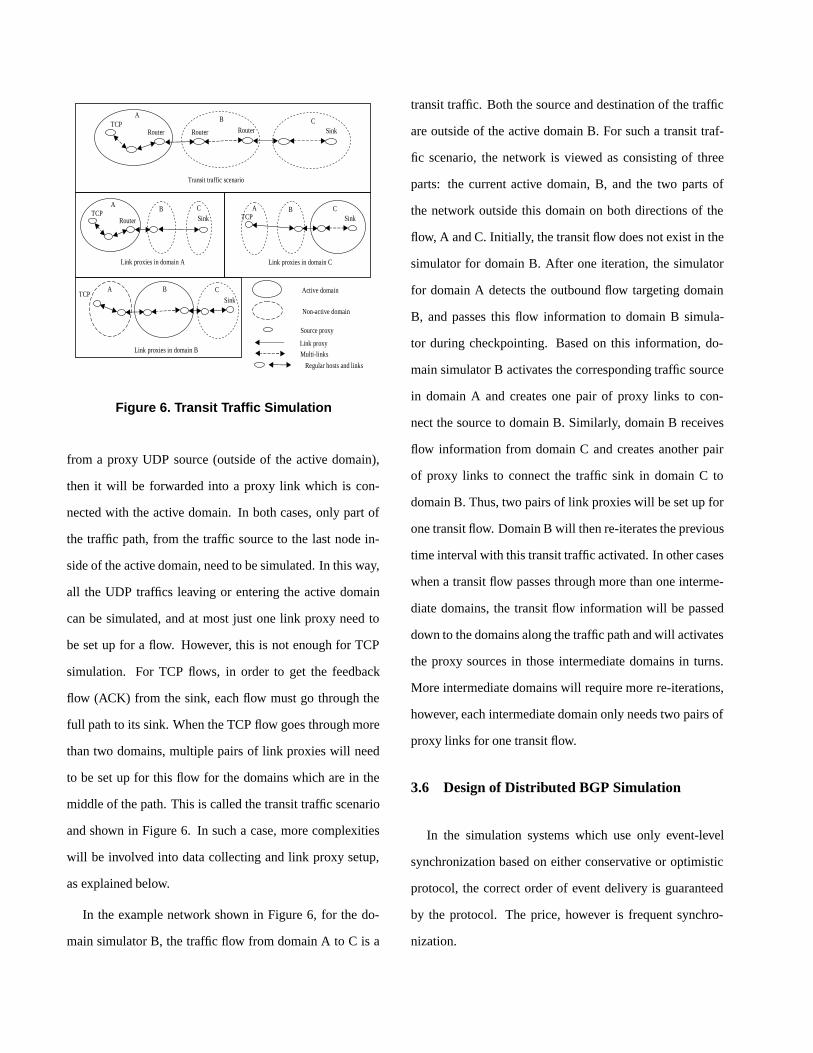
3.5 Transit Traffic Simulation
In Genesis, each domain simulator focuses only on the
simulation of its active domain. Thus, in the simulation of
UDP traffic, any packet sent from a UDP source inside the
active domain stops at the border of the active domain and
does not need to be forwarded further. If a packet is sent
TCPRouter RouterRouter
Transit traffic scenario
A B
SinkC
TCPRouter
Link proxies in domain A
AB
SinkC
TCP
Link proxies in domain C
A BSink
C
TCP
Link proxies in domain B
A B
SinkC Active domain
Non-active domain
Source proxy
Link proxy
Multi-links
Regular hosts and links
Figure 6. Transit Traffic Simulation
from a proxy UDP source (outside of the active domain),
then it will be forwarded into a proxy link which is con-
nected with the active domain. In both cases, only part of
the traffic path, from the traffic source to the last node in-
side of the active domain, need to be simulated. In this way,
all the UDP traffics leaving or entering the active domain
can be simulated, and at most just one link proxy need to
be set up for a flow. However, this is not enough for TCP
simulation. For TCP flows, in order to get the feedback
flow (ACK) from the sink, each flow must go through the
full path to its sink. When the TCP flow goes through more
than two domains, multiple pairs of link proxies will need
to be set up for this flow for the domains which are in the
middle of the path. This is called the transit traffic scenario
and shown in Figure 6. In such a case, more complexities
will be involved into data collecting and link proxy setup,
as explained below.
In the example network shown in Figure 6, for the do-
main simulator B, the traffic flow from domain A to C is a
transit traffic. Both the source and destination of the traffic
are outside of the active domain B. For such a transit traf-
fic scenario, the network is viewed as consisting of three
parts: the current active domain, B, and the two parts of
the network outside this domain on both directions of the
flow, A and C. Initially, the transit flow does not exist in the
simulator for domain B. After one iteration, the simulator
for domain A detects the outbound flow targeting domain
B, and passes this flow information to domain B simula-
tor during checkpointing. Based on this information, do-
main simulator B activates the corresponding traffic source
in domain A and creates one pair of proxy links to con-
nect the source to domain B. Similarly, domain B receives
flow information from domain C and creates another pair
of proxy links to connect the traffic sink in domain C to
domain B. Thus, two pairs of link proxies will be set up for
one transit flow. Domain B will then re-iterates the previous
time interval with this transit traffic activated. In other cases
when a transit flow passes through more than one interme-
diate domains, the transit flow information will be passed
down to the domains along the traffic path and will activates
the proxy sources in those intermediate domains in turns.
More intermediate domains will require more re-iterations,
however, each intermediate domain only needs two pairs of
proxy links for one transit flow.
3.6 Design of Distributed BGP Simulation
In the simulation systems which use only event-level
synchronization based on either conservative or optimistic
protocol, the correct order of event delivery is guaranteed
by the protocol. The price, however is frequent synchro-
nization.

In Genesis, we take advantage of coarse granularity syn-
chronization for TCP and UDP traffics, and at the same
time synchronize BGP update messages by doing extra roll-
backs, to reflect the actual routing dynamics in the network.
Simulators are running independently of each other within
one iteration. To simulate BGP routers separately from the
Genesis domain in each parallel AS domain simulator, and
to make them produce BGP update messages for its neigh-
bor domains, we introduced proxy BGP neighbor routers.
Those are routers mirroring their counterparts which are
simulated by other simulators. The proxy BGP routers do
not perform the full routing functionality of BGP. Instead,
they maintain the BGP sessions and collect the BGP update
messages on behalf of their counterpart routers.
At the synchronization point in Genesis, the BGP up-
date messages collected in the proxy BGP routers, if there
are any, are forwarded to the corresponding destination AS
domain simulators through a component called BGP agent.
These update messages are delivered to the BGP agent in
the destination AS domain through a Farmer-Agent frame-
work, and are distributed there to the BGP routers which are
the destinations of these messages. The proxy BGP router
and BGP agent framework are shown in Figure 7.
This framework enables the system to exchange real
BGP message data among Genesis simulators. But this is
not a full solution yet. Within the independent simulation
of one iteration in Genesis, the BGP routers produce up-
date messages for their neighbors, but do not receive update
messages from their neighbors in other AS domains. Had
they received these update messages, as it happens in an
event-level synchronization simulation system, they would
have probably produced different update messages. In addi-
UPDATE
Proxy BGP A
AS-A AS-B
BGP Agent
BGP A Proxy BGP B
BGP B
AS-B
BGP Agent
Farmer
Genesis Simulator 1 UPDATE
UPDATEAS-A
message forward in simulation
Active Domain
Active Domain
Genesis Simulator 2
message forward in Agent/Farmer
Figure 7. Proxy BGP Routers and BGP Agents
tion, the routing might also have been changed. To simulate
BGP protocol correctly, these BGP updates need to be exe-
cuted in their correct time-stamp order in each BGP router.
Genesis achieved this event-level synchronization for BGP
updates by doing extra rollbacks.
During the Genesis checkpoint after one time interval,
the BGP agent in each AS domain collects BGP update
messages from other BGP agents. If it receives some up-
date messages for the previous interval, it will force the AS
domain simulator to rollback to the start time of the previ-
ous interval. Then, it inserts all the received update mes-
sages into its future event list. Its domain simulator will re-
simulate the time interval again, and will “ receive” these up-
date messages at the correct simulation time and will react
to them correspondingly. The BGP messages produced in
the current execution might be different from the once seen
at previous one. Hence, the rollback process might continue
in domain simulators until all of them reach a global con-
vergence (the update messages in subsequent rollback iter-

ations are the same for each domain). Figure 8 shows the
flowchart of rollback in the BGP agent. High cost of check-
pointing the network state makes it impractical to introduce
separate rollbacks for BGP activities. Hence, the UDP/TCP
traffic checkpoints are used for all rollbacks in Genesis.
Rollback
Convergence test
Insert received remote BGP future events into
event list
BGP message exchanging during
check-pointing
Simulation
Continue
Resume simulation
No
Yes
Figure 8. Synchronization for BGP UpdateMessages
3.7 Design of Memory Distributed Simulation
Memory distribution is particularly challenging in Gen-
esis, because of its special coarse granularity synchroniza-
tion approach. In Genesis, within one time interval, one
domain simulator is working independently of others, sim-
ulating the partial traffics flowing within or through that do-
main. Other parts of these traffics, which are outside of that
domain, are simulated by proxy links which compute the
packet delays and losses based on flow “summaries” pro-
vided by the outside domain simulators. If the network in-
formation is completely distributed among the domain sim-
ulators, each one has information about only a part of the
network. Hence, these simulators cannot simulate global
traffics independently because information about some flow
sources or destinations, or both will not be there. We should
notice the difference here from other event-level synchro-
nization systems. In those systems, to simulate distributed
network, each individual event crossing the boundary is
forwarded to remote simulators regardless of its “seman-
tic meaning” . Hence such parallel simulators do not need
to simulate global flows independently, but they must syn-
chronize their execution tightly.
In Genesis solution, each domain uses traffic proxies that
work on behalf of their counterparts in the remote domains.
Traffic proxies send or receive TCP or UDP data packets as
well as acknowledgment packets according to the produced
feedbacks. To simulate inter-domain flows, partial flows are
constructed between local hosts and proxy hosts. Thus, in
the simulation of one AS domain, the simulator just simu-
lates one part of an inter-domain traffic by using proxy hosts
and proxy links, as shown in Figure 9.
Proxy Host
Proxy Host
Proxy Host
Inter-domain traffic
Inter-domain traffic
AS Domain Simulator
Host
Proxy Host
Proxy Link
Figure 9. Proxy Hosts and Inter-domain Traffic
The actual traffic path between local hosts and remote
hosts must be decided by inter-AS routing. For example,
inter-AS routing changes can cause remote inbound traffic

to enter the current AS domain from different entry points,
thus routing the flow through a different path inside the do-
main. We developed a method, described below, to con-
struct these remote traffic paths and to automatically adjust
them to reflect the current inter-AS routing decision.
To support distributed memory simulation in Genesis,
changes were made to both DML definition and SSFNet
based implementation.
Global routing information consistency: To compute
global routing in separate simulations, each of which has
only a part of the network, IP address consistency is re-
quired to make the routers understand the routing update
messages. In addition, we use BGP proxies and traffic prox-
ies to act on behalf of their counterparts. To use routing
data, these proxies need to use the IP addresses of their
counterparts when they produce traffic packets. We used
a global IP address scheme for the whole network, and in-
troduced a mechanism of IP address mapping, which trans-
lates local addresses to and from global addresses used
in our BGP update messages. In our global IP address
scheme, domains are assigned different IP address blocks
to avoid address conflicts among domain simulators. Inter-
domain routing information is stored based on these global
addresses. Each proxy host stores the IP address of its coun-
terpart host which has a global IP address. When packets
are sent from proxy hosts, the IP addresses in the packet
headers would be replaced with corresponding global IP
addresses. In this way, the addresses in these packets are
consistent with the routing information and can be correctly
routed to the destinations.
Remote host, traffic and link: Those definitions were
added to the current DML definitions for SSFNet [15]. Re-
mote host defines the traffic host (source or sink) which is
not within the current simulating domain, and specifies the
global IP address for this proxy. Remote traffic pattern ex-
tends SSFNet to allow the definition of a traffic which will
use proxy IP address instead of its own local IP address.
Remote link is defined to connect the remote host to the cur-
rent domain, and it is implemented as a Genesis proxy link
which can adjust its link delay and applied packet drop rates
during the simulation.
Proxy Host
AS Domain Simulator
Host
BGP
BGP
Global routing decision
Proxy Host
…………Proxy
Switch
Host
Figure 10. Remote Traffic Path Constructionwith Proxy Switch
Remote traffic path construction: The difficult part of
remote traffic path construction was to decide how to con-
nect proxy hosts to the current AS domain. Changes in inter-
AS routing decision might change the entry (exit) point of
traffic packets to (from) the domain. Such a change cannot
be determined during the network construction phase. We
designed a structure which connected remote traffic hosts
to a proxy switch, instead of connecting them to any entry
point directly, as shown in Figure 10. When a packet sent
by a proxy host reaches the proxy switch, the proxy switch
will lookup an internal mapping from flow id to the current
inter-AS routing table, and will forward this packet via the

correct inbound link to one of the BGP routers on the do-
main boundary. If the inter-AS routing is changed by some
BGP activities later, the proxy switch will automatically ad-
just its internal mapping, and the packets with the same flow
id will be forwarded to a different inbound link.
4. Performance Evaluation
4.1 Non-BGP Network Simulation Experiments
Our first set of experiments for the Genesis involved two
sample network configurations, one with 64 nodes and 576
UDP and TCP flows, the other with 27 nodes and rich inter-
connection structure with 162 UDP and TCP flows. These
networks are symmetrical in their internal topology. We
simulated them on multiple processors by partitioning them
into different numbers of domains with varying number of
nodes in each domain. The rate at which packets are gener-
ated and the convergence criterion are varied.
All test were run on up to 16 processors (always the num-
ber of processors used is equal to the number of domains)
on Sun 10 Ultrasparc and 800 MHz IBM Netfinity worksta-
tions. For both architectures, the machines were intercon-
nected by the 100Mbit Ethernet.
For the 64-node network, the smallest domain size is
four nodes; there is full connectivity among these four
nodes. Four such domains together constitute a larger do-
main in which there is full connectivity between the four
sub-domains. Finally, four large domains are fully con-
nected and form the entire network configuration for the
64-node network, as shown in Figure 11.
Each node in the network is identified by three digits
a.b.c, where a,b,c is greater than or equal to 0 and less than
2
2.0.2
3
3.0.2
1
1.0.2
00.0.0
0.0.2
0.0.1
0.0.30.1.2
0.2.2 0.3.2
Figure 11. 64-node Configuration ShowingFlows from a Sample Node to Other NodesIn the Network
or equal to 3. Each digit identifies domain, sub-domain and
sub-sub-domain and node rank, respectively, within the the
higher level structure.
Each node has nine flows originating from it. Symmetri-
cally, each node also acts as a sink to nine flows. The flows
from a node a.b.c go to nodes:
a.b.(c + 1)%4 a.b.(c + 2)%4 a.b.(c + 3)%4
a.(b + 1)%4.c a.(b + 2)%4.c a.(b + 3)%4.c
(a + 1)%4.b.c (a + 2)%4.b.c (a + 3)%4.b.c
Thus, this configuration forms a hierarchical and symmetri-
cal structure on which the simulation is tested for scalability
and speedup.
The 27-node network is an example of Private Network-
Network Interface (PNNI) network [1] with a hierarchical
structure. The main feature of PNNI protocols is “scalabil-
ity” , because the complexity of routing does not increase
drastically as the size of the network increases. Although

we do not support simulation of PNNI protocols in Gene-
sis, we took this network model as an interesting test case
for Genesis approach. The smallest domain of this 27-node
network is composed of three nodes. Three such domains
form a large domain and three large domains form the entire
network, as shown in Figure 12.
Figure 12. 27-node Configuration and theFlows from the Sample Node
In the 27-node network, each node has six flows to other
nodes in the configuration and is receiving six flows from
other nodes. The flows from a node a.b.c can be expressed
as:
a.b.(c + 1)%3 a.b.(c + 2)%3
a.(b + 1)%3.c a.(b + 2)%3.c
(a + 1)%3.b.c (a + 2)%3.b.c
In a set of measurements, the sources at the borders of
domains produce packets at the rate of 20000 packets per
second for half of the simulation time. The bandwidth of
the link is 1.5Mbps. Thus, certain links are definitely con-
gested. For the other half of the simulation time, these
sources produce 1000 packets per second. Since such flows
require less bandwidth than provided by the links connected
to each source, congestion is not an issue. All other sources
produce packets at the rate of 100 packets per second for
the entire simulation. The measurements were done with
the Telnet traffic source that generates packets with constant
size of 500 bytes.
Speedup was measured in three cases involving (i)
feedback-based protocols, (ii) non-feedback based proto-
cols, and (iii) the mixture of both, with UDP traffic con-
stituting 66% of flows and TCP traffic making up the rest of
the flows. We noticed that if mixed traffic involves a signif-
icant amount of non-feedback based traffic, then it requires
fewer iterations over each time interval and hence yields
greater speedup up than the feedback based traffic alone.
Table 1. Measurements Results (Runtime inSeconds) for UDP Traffic. Large DomainsContain 9 or 16 Nodes and Small DomainsContain 3 or 4 Nodes
Networks 27-nodes 64-nodesNon-decomposed Network 3885.5 1714.5Network with Large Domains 729.5 414.7Network with Small Domains 341.9 95.1Speedup 11.4 18.0Distributed Efficiency 126% 112%
Table 1 presents a small subset of the timing results ob-
tained from the simulation runs. It shows that partitioning
the large network into smaller individual domains and sim-
ulating each on an independent processor can yield a signif-
icant speedup.
Initial implementation of feedback based protocols used
delays from the previous iteration as a starting value for the
next iteration, leading to modest speedup, as shown in Ta-

Table 2. Measurements Results (Runtime inSeconds) for TCP Traffic. Large DomainsContain 9 or 16 Nodes and Small DomainsContain 3 or 4 Nodes
Networks 27-node 64-nodeNon-decomposed Network 357.383 1344.198Network with Large Domains 319.179 1630.029Network with Small Domains 93.691 223.368Speedup 3.81 6.02Distributed Efficiency 42.3% 37.5%
ble 2. The fixed point solution delay lays in between the
delays measured in the two subsequent iterations. Hence, a
delay for each flow used in the next iteration is a function
of the delays from the current and previous iterations. As
expected, using this method of computing delay improves
the Genesis performance. This is shown in Figure 13 for
64-node domains with mixed traffic. If dold is the previous
estimate of the delay, and dm is currently observed values
of the delay, then the new estimate of the delay is computed
as dnew = a ∗ dm + (1 − a) ∗ dold, where 0 < a < 1.
Varying values of the parameter a impacts the responsive-
ness of the delay estimate to new and old values of observed
delays. As a result, a impacts the speed of the simulation
by increasing/decreasing the time required for convergence,
the optimum value of a is 0.5.
To measure the accuracy of the simulation runs, queue-
monitors were placed along internal links along which con-
gestion is most prevalent. These queue-monitors indicated
that the number of packets dropped and the queue-sizes dif-
fered less than 1% from the corresponding values measured
over the sequential simulation of the entire network for both
the feedback and non-feedback based protocols. Another
measure of accuracy was based on the long range dependent
64 node configurations (Mixed Traffic)
01000200030004000500060007000
0 15 30 45 60
Simulation Time (Sec)
Rea
l Tim
e (S
ec)
64-1
64-4
64-16
Figure 13. Speedup Achieved for 64-node Net-work for Mixed Traffic TCP-1/3 UDP-2/3
behavior of aggregation of TCP flows that was expected to
be self-similar. We calculated the Hurst parameter on se-
lected links with heavy TCP traffic using rescaled adjusted
range statistic and arrived at the same value of 0.699 for
both a sequential simulation of the entire network and the
Genesis domain-based simulation.
4.2 Campus Network Model Experiments
4.2.1 Simulation Model
To test the performance and scalability of BGP simula-
tions and memory distributed simulations in Genesis, we
use a modified version of the baseline model defined by the
DARPA NMS community [11]. The topology for the model
that we are using can be visualized as a ring of nodes, where
each node (representing an AS domain) is connected to one
node preceding it and another one succeeding it. We re-
fer to each node or AS domain as the “campus network” , as
shown in Figure 14. Each of the campus networks is similar
to the others and consists of four subnetworks. In addition,
there are two additional routers not contained in the subnet-
work, as shown in the diagram.
The subnetwork labeled Net 1 consists of three routers

0:0
0:1
0:2
1:0
1:1
1:2
1:3
1:4
1:5
4
5
2:0 2:1
2:3
2:5
2:6
2:2
2:4
3:0 3:1
3:2 3:3
Net 1 Net 2
Net 3
Net 4
Figure 14. One Campus Network
in a ring, connected by links with 5ms delay and 2Gbps
bandwidth. Router 0 in this subnetwork acts as a BGP bor-
der router and connects to other campus networks. Subnet-
work 2 consists of 4 UDP servers. Subnetwork 3 contains
seven routers with links to the LAN networks as shown in
the diagram. Each of the LAN networks has one router and
four different LAN’s consisting of 42 hosts. The first three
LAN’s have 10 hosts each and the fourth LAN has 12 hosts.
Each of the hosts is configured to run as a UDP Client. Sub-
network 4 is similar to Subnetwork 3, so internal links and
LAN’s have the same property as those in Subnetwork 3.
The traffic that is being exchanged in the model is gen-
erated by all the clients in one domain choosing a server
randomly from the Subnetwork 1 in the domain that is a
successor to the current one in the ring. We used differ-
ent send-intervals of 0.1, 0.05 and 0.02 second to vary the
traffic intensities, and used different numbers of nodes (AS
domains) to vary the size of the network. Each simulation
was run for 400 seconds of the simulated time.
All tests were run on up to 30 processors on Sun 10
Ultrasparc workstations, which were interconnected by a
100Mbit Ethernet. One of these workstations had 1G large
memory, and each of the others had at least 256M dedicated
memory. In the simulations under distributed Genesis, the
number of processors used was equal to the number of cam-
pus networks.
4.2.2 Synchronization Convergence on BGP Bursts
In BGP network simulations, the first round of BGP up-
date message burst happens when AS domains start to ex-
change BGP information to set up the global inter-AS rout-
ing. In Genesis, AS domains are simulated distributively,
and BGP update messages are synchronized by re-iterating
over one time interval until the BGP messages exchanged
among domains converge (no more changes) on that inter-
val, as we showed in Figure 8. We measured the number
of re-iterations required by this BGP convergence on dif-
ferent sizes of networks and different network topologies to
evaluate performance.
In our experiments, we also defined the “maximum dis-
tance” in a network as the maximum length of the shortest
paths between any two distributed domains in the network,
where the path length was measured in the number of inter-
mediate distributed domains on the path plus one.
The first set of experiments were done on the baseline
topology as we described earlier, in which the Campus Net-
works (CN) were connected as rings. We measured the con-
vergence of the synchronization for ring sizes of 3, 4, 8 and
12 CNs. Table 3 shows the number of re-iterations needed
in Genesis to converge during the BGP message burst. It
should be noted that the number of needed iterations grows
sub-linearly with the number of domains.
The results show that the number of re-iterations is re-

Table 3. BGP Synchronization Convergencewith Different Ring Sizes (in Number of Cam-pus Networks). Each Genesis Domain hasOne Campus Network.
Ring Size Domains Max Distance Iterations3 3 2 34 4 2 48 8 4 6
12 12 6 8
lated to the size of the network, and is proportional to the
maximum distance of a network. This can be explained as
follows: because in each re-iteration, BGP messages are
exchanged between neighboring distributed domains, thus
they propagate to the domains with distance one to them-
selves. The maximum distance in a network decides how
many re-iterations are needed for BGP decisions from one
distributed domain to reach all the other domains in the net-
work. Any received BGP message might cause response
messages from the receiver and propagate to the rests in the
network, and in each round the number of re-iterations is
also decided by the maximum distance in the network. In
our ring-based topologies, this maximum distance is pro-
portional to the ring size.
It is important that the “maximum distance” is decided
by the distance between distributed domains instead of in-
dividual BGP ASes. In the experiments above, the network
was partitioned on the boundary of each BGP AS. In other
words, each distributed domain had only one BGP AS. As a
result, for a network with large number of BGP ASes, there
will be large number of distributed domains and very likely
the longest distance between two domains will be large and
will need more reiterations to converge on BGP propaga-
tion. However, by grouping neighboring BGP ASes into
one distributed domain, we can reduce the “maximum dis-
tance” of a network, and improve the convergence perfor-
mance.
In the following set of experiments, 24 Campus Net-
works (CN) were connected in a ring, as described in the
previous section earlier. We grouped N adjacent CNs into
one Genesis domain, and constructed each domain distribu-
tively in Genesis domain simulators, as shown in Figure 15.
N was varied as we set it to 8, 6, 3 and 2, thus the “maxi-
mum distance” of each network was, correspondingly, 2, 2,
4 and 6.
Group into Genesis Domains
Domain 1
Domain 2
Campus Network
Figure 15. Grouping Adjacent Campus Net-works
Table 4 shows that by grouping BGP ASes together,
we had reduced the number of distributed domains and
the number of convergence re-iterations. The cost was,
however, the degree of parallelism was also reduced. On
the other hand, because Genesis supports flexible BGP AS
grouping, users have the freedom to select network parti-
tioning schemes. These results give us a hint that a parti-
tioning scheme which can reduce the “maximum distance”
of a network with large number of BGP ASes will improve
the convergence of simulation.
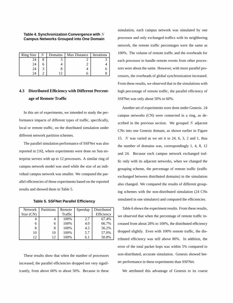
Table 4. Synchronization Convergence with NCampus Networks Grouped into One Domain
Ring Size N Domains Max Distance Iterations24 8 3 2 324 6 4 2 424 3 8 4 624 2 12 6 8
4.3 Distributed Efficiency with Different Percent-
age of Remote Traffic
In this set of experiments, we intended to study the per-
formance impacts of different types of traffic, specifically,
local or remote traffic, on the distributed simulation under
different network partition schemes.
The parallel simulation performance of SSFNet was also
reported in [16], where experiments were done on Sun en-
terprise servers with up to 12 processors. A similar ring of
campus network model was used while the size of an indi-
vidual campus network was smaller. We computed the par-
allel efficiencies of those experiments based on the reported
results and showed them in Table 5.
Table 5. SSFNet Parallel Efficiency
Network Partitions Remote Speedup DistributedSize (CN) Traffic Efficiency
4 4 100% 2.7 67.4%6 6 100% 4.0 66.7%8 8 100% 4.5 56.2%
10 10 100% 5.7 57.0%12 12 100% 6.1 50.8%
These results show that when the number of processors
increased, the parallel efficiencies dropped not very signif-
icantly, from above 60% to about 50%. Because in these
simulation, each campus network was simulated by one
processor and only exchanged traffics with its neighboring
network, the remote traffic percentages were the same as
100%. The volume of remote traffic and the overheads for
each processor to handle remote events from other proces-
sors were about the same. However, with more parallel pro-
cessors, the overheads of global synchronization increased.
From these results, we observed that in the simulations with
high percentage of remote traffic, the parallel efficiency of
SSFNet was only about 50% to 60%.
Another set of experiments were done under Genesis. 24
campus networks (CN) were connected in a ring, as de-
scribed in the previous section. We grouped N adjacent
CNs into one Genesis domain, as shown earlier in Figure
15. N was varied as we set it to 24, 6, 3, 2 and 1, thus
the number of domains was, correspondingly 1, 4, 8, 12
and 24. Because each campus network exchanged traf-
fic only with its adjacent networks, when we changed the
grouping scheme, the percentage of remote traffic (traffic
exchanged between distributed domains) in the simulation
also changed. We compared the results of different group-
ing schemes with the non-distributed simulation (24 CNs
simulated in one simulator) and computed the efficiencies.
Table 6 shows the experiment results. From these results,
we observed that when the percentage of remote traffic in-
creased from about 28% to 100%, the distributed efficiency
dropped slightly. Even with 100% remote traffic, the dis-
tributed efficiency was still above 80%. In addition, the
error of the total packet hops was within 5% compared to
non-distributed, accurate simulation. Genesis showed bet-
ter performance in these experiments than SSFNet.
We attributed this advantage of Genesis to its coarse

Table 6. Distributed Efficiency in Genesis SimulationFull Network Genesis Remote Total Packet-hop Speedup Distributed
Size (CN) Domains Traffic Difference Efficiency24 Non-decomposed 0%24 4 28.6% 3.8% 4.15 104%24 8 50.0% 3.2% 7.73 96.7%24 12 66.7% 4.0% 11.0 91.7%24 24 100% 5.0% 19.8 82.6%
granularity synchronization approach. Unlike conventional
event-level synchronizations in which each individual re-
mote packet (event) need to be exchanged and synchro-
nized, Genesis aggregated these simulation data and re-
duced both the amount of data exchange and frequency of
synchronization. As the result, higher percentage of remote
traffic did not introduce significant synchronization over-
heads in Genesis, as they usually did in other conventional
simulation systems.
4.3.1 Performance of Simulations on Distributed
Memory
0
100
200
300
400
500
600
10 15 20 30
No. of AS Domains
Mem
ory
Usa
ge (M
b)
SSFNetGenesis
Figure 16. Memory Usage of SSFNet and Gen-esis for Simulating Different Sizes of BGPNetworks. Memory Sizes of Genesis ShownAbove are the Requirements for Single ASSimulator
Genesis distributively constructs and simulates BGP
routers in AS domain simulators. To measure scalability
of this solution in terms of network size, we simulated BGP
networks of 10, 15, 20 and 30 AS domains, each run by a
Sun 10 Ultrasparc workstation with 256Mb of memory. As
shown in Figure 16, when the number of AS domains in-
creases, unlike SSFNet, the memory usage of one Genesis
AS simulator does not increase significantly. As a result,
by utilizing more computers with smaller memories, we are
able to simulate much larger networks.
0
50
100
150
200
250
300
350
400
0.1 0.05 0.02
Send Interval (second)
Mem
ory
Usa
ge (M
b)
SSFNetGenesis
Figure 17. Memory Usage of SSFNet and Gen-esis for 20-AS BGP Network Simulations withDifferent Send Rates
Memory usage of simulation is related not only to the
static network size, but also to the traffic intensity. We
increased the traffic intensity by reducing the traffic send-
interval from 0.1 to 0.05 and 0.02 second. As shown in
Figure 17, although we did not observe very big changes in
memory usage in SSFNet on this campus network model,
Genesis showed even smaller increase in memory size with

the same changes in traffic (thanks to its smaller base mem-
ory size).
As we have shown, Genesis achieved execution speedups
thanks to its coarse granularity synchronization mechanism.
In addition, despite the extra overheads introduced by dis-
tributing the network, good speedups where achieved for
10, 15, 20 and 30 domain simulators with BGP routers.
The Genesis domains were defined by the AS boundaries.
Figure 18 shows the speedups of simulations for these net-
works.
0
2
4
6
8
10
12
14
16
10 15 20 30
No. of AS Domains
Spee
dup
Figure 18. Speedup Achieved for Simulationsof Different BGP Network Sizes
Figure 19 shows that Genesis achieved higher speedups
with higher traffic intensities. This is because with higher
traffic intensity, more events need to be simulated in a fixed
simulation time. Theoretical analysis tells us that sequen-
tial simulation time includes terms of order O(n ∗ log(n)),
due to sorting event queues. Genesis distributes the simula-
tion among domain simulators, which reduces the number
of events needed to be simulated by one simulator, so it can
achieve higher speedups when the traffic increases as well
as when the network size increases.
To measure the accuracy of the simulation runs, we mon-
itored the per flow end-to-end packet delays and packet drop
rates. We compared the results from distributed Genesis
with the results from sequential simulations under SSFNet,
and calculated the relative errors. Our results showed that
for most of the flows, the relative errors of both packet de-
lay and drop rate were within the range from 2% to 10%,
while a small number of individual flows had higher rela-
tive errors of up to 15% to 20%. Considering the fact that in
a simulation with large number of flows, the network condi-
tion was mainly determined by the aggregated effects of sets
of flows, we calculated the root-mean-square of the relative
errors on each set of flows which went through the same
domain. These root-mean-squares of relative errors were
below 5%, which seems sufficiently close approximation of
the sequential simulation for many applications.
0
2
4
6
8
10
12
14
0.1 0.05 0.02
Send Interval (second)
Spee
dup
Figure 19. Speedup Achieved for 20-AS BGPNetwork Simulations with Different SendRates
Simulation results showed that by fully distributing the
simulation in Genesis, we gained the scalability of mem-
ory size. In addition, the parallel simulation in Genesis
still achieved performance improvement in this distributed
framework, compared to sequential simulations.

4.3.2 Impacts of On-going BGP Activities
We have shown the synchronization convergence on BGP
bursts under Genesis in section 4.2.2. When a BGP update
message propagation happens, Genesis re-iterates over the
same time interval until the propagation converges. Each re-
iteration consumes simulation run time. When BGP update
message propagations happen periodically during the simu-
lation, the additional run time required by these re-iterations
will decrease the speedups achieved by utilizing parallel
simulation. An interesting question is how such on-going
BGP activities would affect the simulation performance.
To investigate this question, we introduced BGP session
crashes into our experiments. The simulation time was fixed
at 400 seconds for 20 AS’s and, correspondingly 20 Sun
10 Ultrasparc workstations. The BGP session between two
neighboring AS domains, campus network 3 and 4, crashed
every D seconds, each time staying down for D/2 seconds,
and then coming back and staying alive for another D/2
seconds.
As expected, in the simulation time intervals in which the
specified BGP session went down, BGP update messages
were propagated causing the broken routes to be withdrawn
and back up routes being set up. Accordingly, data packet
flows also changed and used the new routes. When that
BGP session came back again, BGP update messages prop-
agated again and re-established the broken routes. In either
case, the relevant time interval had to be re-iterated again
and again until it converged. So these intervals were “slow-
down” periods. The time intervals with no BGP propaga-
tions were “speed-up” periods thanks to the novel parallel
simulation mechanism used by Genesis. As a result, the
proportion of the “slow-down” time in the whole simula-
tion time affects the overall speedup: the less frequently
the crashes happen, the greater the speedup that can be
achieved. When the frequency of BGP crashes is not high,
these “slow-down” periods will not significantly slow down
the progress of the simulation.
On the other hand, the length of the time interval also
affects the total re-iteration time. Ideally, smaller the length
of the time interval, shorter the total re-iteration time. But
there are two other factors which benefit from longer inter-
vals. First, small interval length increases the synchroniza-
tion and checkpointing overheads between intervals and can
overwhelm the simulation speedup. Second, if the interval
length is too small to cover the BGP propagation period,
then the next time interval will need to be re-iterated in ad-
dition to the current one.
We varied the value of D from 80 to 60, 40 and then 20
seconds, and also used different lengths of iteration time in-
tervals for Genesis checkpointing, denoted as T , which was
set to 20, 10 and 5 seconds. Figure 20 shows the speedups
achieved in these experiments.
0
1
2
3
4
5
6
7
20 40 60 80
Crash Interval D (sec.)
Sp
eed
up T = 20 sec.
T = 10 sec.T = 5 sec.
Figure 20. Speedup Achieved with BGPCrashes Run on 20 Processors. D DenotesCrash Interval Length. T Stands for Check-point Interval Length
In our experiments, we were able to reduce the iteration

time interval length to 5 seconds, as we observed that the
BGP propagation in our experiment scenario was around 3
seconds. As shown in Figure 20, we achieved significant
speedups for crash intervals greater than 40 seconds. Be-
sides the crash frequency, the iteration length also played
an important role in the performance. When using big iter-
ation interval length of 20 seconds, Genesis failed to pro-
duce any speedup with short crash interval of 40 seconds.
These results indicate that a method to automatically decide
the optimal iteration length for a given simulation scenario
could be a valuable future extension that can improve the
overall performance of the system.
5. Conclusions
The need for scalable and efficient network simulators
increases with the rapidly growing complexity and dynam-
ics of the Internet. In this paper we introduced a novel
scheme, implemented in Genesis, to support scalable, ef-
ficient parallel network simulation. Our results indicate
that the superlinear speedup for the single iteration step is
possible and is the result of the non-linear complexity of
the network simulation. Our approach achieved significant
speedup in the simulations of different network scenarios.
In addition to the speedup, the advantages of the pre-
sented method include fault tolerance, ability to integrate
simulations and models in one run and support for truly dis-
tributed execution. When one of the participating processes
fails, the rest can use the old delay and packet loss data to
continue a simulation. When the only information available
about a domain are delays across the domain and its out-
flows, the simulation of the other parts of the networks can
directly use these data to perform the simulation.
We also demonstrated that our system can work effi-
ciently with fully distributed network memory. This design
reduces and makes scalable the memory size requirement
for large-scale network simulations. As a result, Genesis
is able to simulate huge networks using limited computer
resources.
The memory size required by BGP network simulation
increases very fast when the number of BGP routers and
AS domains increases. As a result, the simulation of large
BGP networks was hindered by the memory size limitation.
Genesis offers a new approach to simulating BGP on dis-
tributed memory that is scalable both in terms of simulation
time and the required memory.
6 Acknowledgments
We would like to acknowledge the contributions of
Anand Sastry, Kiran Madnani, Qiuju Gu and Rashim Gupta
to the development and implementation of the ideas pre-
sented herein.
References
[1] Bhatt, S., R. Fujimoto, A. Ogielski, and K. Perumalla, Par-
allel Simulation Techniques for Large-Scale Networks. IEEE
Communications Magazine, 36, 1998.
[2] Carothers, C., and B. Szymanski. Checkpointing Multi-
threaded Programs. Dr. Dobb’s Journal, 15(8):45–60, August
2002.
[3] Chandy, K.M., and R. Sherman. Space-time and simulation.
Proc. of Distributed Simulation, Society for Computer Simu-
lation, 53–57, 1989.
[4] Dartmouth College. DaSSFNet(Dartmouth SSFNet). See web
site at http://www.cs.dartmouth.edu/research/DaSSF/.

[5] Fujimoto, R.M. Parallel discrete event simulation. Comm. of
the ACM, 33:31–53, Oct. 1990.
[6] Klein, L.R. The LINK Model of World Trade with Appli-
cation to 1972-1973. Quantitative Studies of International
Economic Relations, Amsterdam, North Holland, 1975.
[7] Law, L.A., and M. G. McComas. Simulation software for
communication networks: the state of the art. IEEE Comm.
Magazine, 32:44–50, 1994.
[8] Mandani, K., and B. Szymanski. Integrating Distributed
Wireless Simulation Into Genesis Framework. Proc. of Sum-
mer Computer Simulation Conference.
[9] Nicol, D. Comparison of network simulators revisited. Avail-
able at http://www.ssfnet.org/Exchange/gallery/dumbbell/
dumbbell-performance-May02.pdf, May 2002.
[10] Liu, Y., and B. Szymanski. Distributed Packet-Level Sim-
ulation for BGP Networks under Genesis. Proceedings of
2004 Summer Computer Simulation Conference (SCSC’04).
July 25 - 29, 2004, San Jose, CA.
[11] NMS (Network Modeling and Simulation DARPA
Program) baseline model. See web site at
http://www.cs.dartmouth.edu/ nicol/NMS/baseline/.
[12] ns(network simulator). See web site at http://www-
mash.cs.berkeley.edu/ns.
[13] PDNS(Parallel/Distributed NS). See web site at
http://www.cc.gatech.edu/computing/compass/pdns/.
[14] Shi, Y., N. Prywes, B. Szymanski, and A. Pnueli. Very High
Level Concurrent Programming. IEEE Trans. Software Engi-
neering, SE-13:1038–1046, Sep. 1987.
[15] SSFNet(Scalable Simulation Framework Network Models).
See web site at http://www.ssfnet.org/homePage.html.
[16] SSF Research Network. Java SSFNet parallel performance.
Available at http://www.ssfnet.org/parallelSolaris.pdf.
[17] Stallings, W.. High Speed Networks: TCP/IP and ATM De-
sign Principles, Prentice Hall, Upper Saddle River, NJ, 1998.
[18] Szymanski, B., Y. Liu and R. Gupta. Parallel Network Sim-
ulation under Distributed Genesis. In Proceedings of the 17th
Workshop on Parallel and Distributed Simulation, June 2003.
[19] Szymanski, B., J.-F. Zhang, and J. Jiang. A Distributed Sim-
ulator for Large-Scale Networks with On-Line Collaborative
Simulators. Proc. European Multisimulation Conference -
ESM99, Warsaw, Poland, SCS Press, II:146–150, June, 1999.
[20] Szymanski, B., Y. Liu, A. Sastry, and K. Madnani, Real-
Time On-Line Network Simulation. Proc. of the 5th IEEE
International Workshop on Distributed Simulation and Real-
Time Applications DS-RT 2001, August 13-15, 2001, IEEE
Computer Society Press, Los Alamitos, CA, 2001, pp. 22-29.
[21] Szymanski, B., Q. Gu, and Y. Liu. Time-Network Parti-
tioning for Large-Scale Parallel Network Simulation Under
SSFNet. Proc. of Applied Telecommunication Symposium,
ATS2002, B. Bodnar (edt), San Diego, CA, April 14-17, SCS
Press, pp. 90-95.
[22] Szymanski, B., A. Saifee, A. Sastry, Y. Liu and K. Madnani.
Genesis: A System for Large-scale Parallel Network Simula-
tion. Proc. of the 16th Workshop on Parallel and Distributed
Simulation, pp. 89–96, May 2002.
[23] Szymanski, B., Y. Shi, and N. Prywes. Synchronized Dis-
tributed Termination. IEEE Trans. Software Engineering, SE-
11:1136–1140, Sep. 1987.
[24] Ye, T., D. Harrison, B. Mo, S. Kalyanaraman, B. Szyman-
ski, K. Vastola, B. Sikdar, and H. Kaur. Traffic manage-
ment and network control using collaborative on-line simu-
lation. Proc. International Conference on Communication,
ICC2001, 2001.
[25] Yuksel, M., B. Sikdar, K. S. Vastola, and B. Szymanski.
Workload Generation for ns Simulations of Wide Area Net-
works and the Internet. Proc. Communication Networks and
Distributed Systems Modeling and Simulation Conference,
93–98, SCS Press, 2000.