genie user manual volume 4 app c1 api wsd
DESCRIPTION
genieTRANSCRIPT

DET NORSKE VERITAS SOFTWARE SESAM GeniE User Manual Vol. IV – App. C1
Version 6.6 1 25 Sept 2013
GeniE User Manual
Code checking of beams
Appendix C1 – Implementation of API-WSD
Table of Contents
1. IMPLEMENTATION OF API-WSD (RP 2A-WSD) ............................................................................................ 2
1.1 REVISIONS SUPPORTED ............................................................................................................................................................... 2 1.2 MEMBER AND CONE DESIGN CHECK – API WSD 2002 & 2005 .................................................................................................... 4 1.3 TUBULAR JOINT DESIGN CODE CHECK - API WSD 2002 .............................................................................................................. 8 1.4 TUBULAR JOINT DESIGN CODE CHECK - API WSD 2005 ............................................................................................................ 12 1.5 NOMENCLATURE ...................................................................................................................................................................... 15
1.5.1 Member check API WSD 2002 & 2005 ........................................................................................................... 15 1.5.2 Cone check API WSD 2002 & 2005 ................................................................................................................ 17 1.5.3 Tubular joint check API WSD 2002 ................................................................................................................ 18 1.5.4 Tubular joint check API WSD 2005 ................................................................................................................ 20

DET NORSKE VERITAS SOFTWARE SESAM GeniE User Manual Vol. IV – App. C1
Version 6.6 2 25 Sept 2013
1. IMPLEMENTATION OF API-WSD (RP 2A-WSD)
The implementation of API WSD is according to “Recommended Practice for Planning, Designing and
Constructing Fixed Offshore Platforms—Working Stress Design”.
API RECOMMENDED PRACTICE 2A-WSD (RP 2A-WSD)
TWENTY-FIRST EDITION, DECEMBER 2000
1.1 Revisions supported
ERRATA AND SUPPLEMENT 1, DECEMBER 2002”
The code checks implemented in GeniE cover capacity check of cylindrical members, conical transitions
and tubular joints according to chapter 3 “Structural Steel Design” and chapter 4 “Connections”.
In October 2005 the “ERRATA AND SUPPLEMENT 2” release was published. This release contains a
completely re-written chapter regarding joint capacity check but no other changes which will have effect on
the API WSD code check implementation. The new joint capacity check is implemented in GeniE as a
separate check option.
The joint capacity check part of the API WSD 2005 also includes error/misprint corrections in ERRATA 3,
January 2007.
Select API WSD 2002 or 2005 from the Create
Code Check Run dialog
Define the global (General) parameter regarding
member capped-end forces and joint capacity check
options. Note that the implementation according to
2005 has more options.

DET NORSKE VERITAS SOFTWARE SESAM GeniE User Manual Vol. IV – App. C1
Version 6.6 3 25 Sept 2013
Options:
Cap-end forces included Select when Capped-end forces are included, i.e. the calculated axial
stress includes the effect of the hydrostatic capped-end forces. This
corresponds to an analysis where Wajac has been used.
Individual brace to can end
distance
In previous versions only the minimum distance from brace to can end
was used. GeniE’s new option allows choose between joint’s minimum
or individual brace to can end distance. Ref. Figure 4.3-2 in the 2005
release.
Tolerance Angle User can define azimuthal tolerance angle for joint design. Previous
versions used 5 degrees as default value. This provides the possibility
to define different sets of braces to be used on Joint Punch Check
Analysis. The subdivision in Y-, K- and X- joint axial force patterns
normally considers all members in one plane at a joint. Brace planes
within (±o) of each other may be considered as being in the same
plane.
Use geometric limits The maximum usage factor of actual geometry and the limit geometry
values will be reported to be governing when selecting this option. (If
not selected the usage factor will be based on actual geometry only).
This option is only valid for Sept. 2005 and later versions of API.
Joint Minimum Capacity Regarding section 4.2.3 (and C.4.2.3):
The statement should be interpreted as follows: for critical joints the
requirement that the joint capacity be no less than 50% of the strength
of the incoming brace may be replaced with a requirement that the unit
check of the joint be no more than 85% of the unit check of the brace.
Two user defined options are available:
- Define a cut-off value; if the brace usage factor is less than the
cut-off value the actual usage factor for the brace for the
investigated load case is neglected, i.e. 1.0 is used as brace
usage factor. (Hence, when set to zero the actual brace usage
factor will always be used.)
- Possibility to modify the 85% limit
Required Chord Thickness Select if the required chord/can thickness shall be calculated when the
usage factor is > 1 for actual thickness.
Two user defined options are available:
- Incremental step value: give the step value to be used to
increase the thickness until the usage factor is < 1.
- Boundary condition: the maximum thickness (Tmax) where the
thickness iteration process is stopped without obtaining a usage
factor < 1. As default the Radius is the limit. Alternatively give
the maximum thickness manually.
Note the following:
- If used in combination with “Use geometric limits” the
required thickness calculation will neglect the D/2T limitation.
- If reaching the “Tmax” due to the defined boundary condition
before the calculation gives a usage factor < 1, the text “Tmax”
will be reported.
DET NORSKE VERITAS SOFTWARE SESAM GeniE User Manual Vol. IV – App. C1
Version 6.6 4 25 Sept 2013
- If the user given “Tmax” is less than actual/original thickness
the text “Tmax < T” will be reported.
- For braces with negative gap: If the governing usage factor is
caused by the check of the overlapping brace onto the through
brace as chord the calculations will run until “Tmax” is
reached.
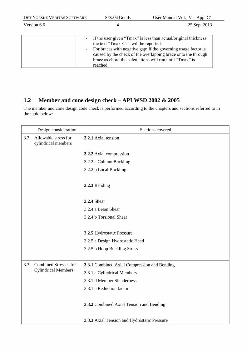
1.2 Member and cone design check – API WSD 2002 & 2005
The member and cone design code check is performed according to the chapters and sections referred to in
the table below:
Design consideration Sections covered
3.2 Allowable stress for
cylindrical members
3.2.1 Axial tension
3.2.2 Axial compression
3.2.2.a Column Buckling
3.2.2.b Local Buckling
3.2.3 Bending
3.2.4 Shear
3.2.4.a Beam Shear
3.2.4.b Torsional Shear
3.2.5 Hydrostatic Pressure
3.2.5.a Design Hydrostatic Head
3.2.5.b Hoop Buckling Stress
3.3 Combined Stresses for
Cylindrical Members
3.3.1 Combined Axial Compression and Bending
3.3.1.a Cylindrical Members
3.3.1.d Member Slenderness
3.3.1.e Reduction factor
3.3.2 Combined Axial Tension and Bending
3.3.3 Axial Tension and Hydrostatic Pressure

DET NORSKE VERITAS SOFTWARE SESAM GeniE User Manual Vol. IV – App. C1
Version 6.6 5 25 Sept 2013
3.3.4 Axial Compression and Hydrostatic Pressure
3.3.5 Safety Factors
3.4 Conical Transitions 1)
3.4.1 Axial compression and Bending
3.4.1.a Cone Section Properties
3.4.1.b Local buckling
3.4.1.c Unstiffened Cone-cylinder Junctions
3.4.1.c.1 Longitudinal Stress
3.4.1.c.2 Hoop Stress
3.4.2 Hydrostatic Pressure
3.4.2.a Cone Design
1) Note that these formulas given for conical transitions in axial compression and bending are also used for
axial tension and that the checks are always performed both for positive and negative resulting bending
stress. With respect to the hoop stress the following approach is used: At the smaller-diameter junction, the
hoop stress is tensile (or compressive) when (fa + fb) is tensile (or compressive). Similarly, the hoop stress
at the larger-diameter junction is tensile (or compressive) when (fa + fb) is compressive (or tensile).
DET NORSKE VERITAS SOFTWARE SESAM GeniE User Manual Vol. IV – App. C1
Version 6.6 6 25 Sept 2013
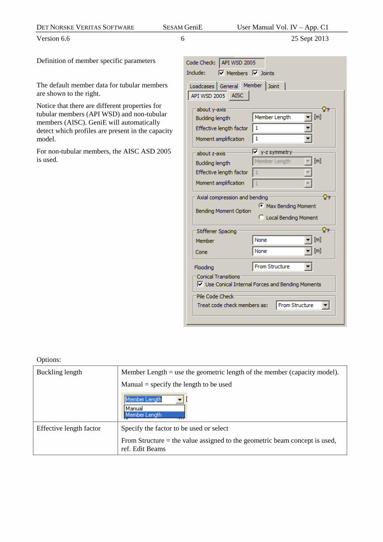
Definition of member specific parameters
The default member data for tubular members
are shown to the right.
Notice that there are different properties for
tubular members (API WSD) and non-tubular
members (AISC). GeniE will automatically
detect which profiles are present in the capacity
model.
For non-tubular members, the AISC ASD 2005
is used.
Options:
Buckling length Member Length = use the geometric length of the member (capacity model).
Manual = specify the length to be used
Effective length factor Specify the factor to be used or select
From Structure = the value assigned to the geometric beam concept is used,
ref. Edit Beams
DET NORSKE VERITAS SOFTWARE SESAM GeniE User Manual Vol. IV – App. C1
Version 6.6 7 25 Sept 2013
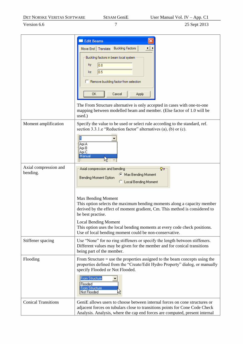
The From Structure alternative is only accepted in cases with one-to-one
mapping between modelled beam and member. (Else factor of 1.0 will be
used.)
Moment amplification Specify the value to be used or select rule according to the standard, ref.
section 3.3.1.e “Reduction factor” alternatives (a), (b) or (c).
Axial compression and
bending.
Max Bending Moment
This option selects the maximum bending moments along a capacity member
derived by the effect of moment gradient, Cm. This method is considered to
be best practise.
Local Bending Moment
This option uses the local bending moments at every code check positions.
Use of local bending moment could be non-conservative.
Stiffener spacing Use “None” for no ring stiffeners or specify the length between stiffeners.
Different values may be given for the member and for conical transitions
being part of the member.
Flooding From Structure = use the properties assigned to the beam concepts using the
properties defined from the “Create/Edit Hydro Property” dialog, or manually
specify Flooded or Not Flooded.
Conical Transitions GeniE allows users to choose between internal forces on cone structures or
adjacent forces on tubulars close to transitions points for Cone Code Check
Analysis. Analysis, where the cap end forces are computed, present internal
DET NORSKE VERITAS SOFTWARE SESAM GeniE User Manual Vol. IV – App. C1
Version 6.6 8 25 Sept 2013
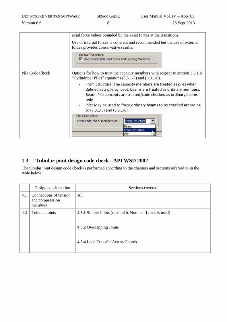
axial force values bounded by the axial forces at the transitions.
Use of internal forces is coherent and recommended but the use of external
forces provides conservative results.
Pile Code Check Options for how to treat the capacity members with respect to section 3.3.1.b
“Cylindrical Piles” equations (3.3.1-5) and (3.3.1-6).
- From Structure: The capacity members are treated as piles when defined as a pile concept, beams are treated as ordinary members.
- Beam: Pile concepts are treated/code checked as ordinary beams only
- Pile: May be used to force ordinary beams to be checked according to (3.3.1-5) and (3.3.1-6).
1.3 Tubular joint design code check - API WSD 2002
The tubular joint design code check is performed according to the chapters and sections referred to in the
table below:
Design consideration Sections covered
4.1 Connections of tension
and compression
members
All
4.3 Tubular Joints 4.3.1 Simple Joints (method b. Nominal Loads is used)
4.3.2 Overlapping Joints
4.3.4 Load Transfer Across Chords

DET NORSKE VERITAS SOFTWARE SESAM GeniE User Manual Vol. IV – App. C1
Version 6.6 9 25 Sept 2013
Joint specific parameters:
Options:
Brace Type Select how to classify the brace type regarding geometry. Alternatives
are:
-manually set to YT, X, K, KTT, KTK
-classify according to geometry
-classify according to loadpath (and geometry)
-interpolate using manual input
Load Transfer Select if load transfer through chord shall be used, ref. API section
4.3.4.
Gap From Structure = use the geometry as defined in the model and
calculate gap values.
None = do not include gap => set gap to zero

DET NORSKE VERITAS SOFTWARE SESAM GeniE User Manual Vol. IV – App. C1
Version 6.6 10 25 Sept 2013
Manual = specify the gap value to be used towards neighbour braces
Through Brace The program will propose the through brace in an overlapping joint
based on:
1. Max. thickness is through-brace
2. Max. diameter is through, when 1. equal
3. Minimum angle with chord is through brace
The user may change this if the situation is different from the proposal.
Weld Thickness For overlapping joint give the lesser of the weld
throat thickness or the thickness t of the thinner
brace.
The joint capacity check requires that the tensile strength of the chord material is defined. If the tensile
strength has not been defined, a tensile strength equal to Yield strength * 1.11 will be used. In such cases the
usage factor from equation (4.1-1) will be based on Fyc = 2/3 of tensile strength.

DET NORSKE VERITAS SOFTWARE SESAM GeniE User Manual Vol. IV – App. C1
Version 6.6 11 25 Sept 2013
When calculating the usage factor for an overlapping brace according to Section 4.3.2 “Overlapping joints”
the capacities according to Section 4.3.1 “Simple Joints” are also checked.
API Figure 4.3.4-1
API Figure 4.3.2-1
It should be noted that the allowable stress
increase factor is accounted for where applicable
based on the load case/combination design
condition. (A manually defined value may also be
specified.)

DET NORSKE VERITAS SOFTWARE SESAM GeniE User Manual Vol. IV – App. C1
Version 6.6 12 25 Sept 2013
1.4 Tubular joint design code check - API WSD 2005
Tubular Joint Design, ERRATA AND SUPPLEMENT 2, OCTOBER 2005 (inclusive error/misprint
corrections in ERRATA 3, January 2007).
To activate this version of the standard the 2005 release
alternative must be selected from the Create Code Check Run
dialog.
The code check is performed according to chapter 4 “Strength of Tubular Joints” and sections referred to in
the table below:
Design consideration Sections covered
4.3 SIMPLE JOINTS 4.3.1 Validity Range
4.3.2 Basic Capacity
4.3.3 Strength Factor Qu
4.3.4 Chord Load Factor Qf 1)
4.3.5 Joints with Thickened Cans
4.3.6 Strength Check
C.4.3.1 Usable strength taken as the lesser of the strengths calculated
based on actual geometrical parameters and the limiting value parameter
for the validity range.
4.4 OVERLAPPING
JOINTS
1) Conservatively positive in-plane bending moment is always used in equation (4.3-2)
The safety factor FS is as default set to 1.6
according to the standard. The actual safety
factor used is 1.6/(increase factor), where the
increase factor is based on the load
case/combination design condition.
Joint specific parameters:

DET NORSKE VERITAS SOFTWARE SESAM GeniE User Manual Vol. IV – App. C1
Version 6.6 13 25 Sept 2013
Options:
Brace Type Select how to classify the brace type regarding geometry. Alternatives
are:
-manually set to YT, X, K, KTT, KTK
-classify according to geometry
-classify according to loadpath (and geometry)
-interpolate using manual input
Gap From Structure = use the geometry as defined in the model and
calculate gap values.
None = do not include gap => set gap to zero
Manual = specify the gap value to be used towards neighbour braces
Through Brace The program will propose the through brace in an overlapping joint
based on:
1. Max. thickness is through-brace
2. Max. diameter is through, when 1. equal
3. Minimum angle with chord is through brace
The user may change this if the situation is different from the proposal.
Critical joint
Select if the joint shall be classified as critical, i.e. if the Minimum
Capacity requirement shall be checked/used.
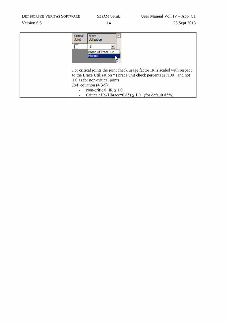
Brace Utilization
If the joint is defined as “critical”, select if the brace utilization factor
shall be automatically read from the member check or alternatively give
a manually defined usage factor (0 < uf < 1). When “Brace Uf From
Run” is selected the relevant braces must be defined as member
capacity models in the capacity manager. If no data found, usage factor
= 1.0 is used. A value of 1.0 is also used when the actual brace usage
factor is less than 0.001 or greater than 1.0.
DET NORSKE VERITAS SOFTWARE SESAM GeniE User Manual Vol. IV – App. C1
Version 6.6 14 25 Sept 2013
For critical joints the joint check usage factor IR is scaled with respect
to the Brace Utilization * (Brace unit check percentage /100), and not
1.0 as for non-critical joints.
Ref. equation (4.3-5):
- Non-critical: IR ≤ 1.0
- Critical: IR/(Ubrace*0.85) ≤ 1.0 (for default 85%)

DET NORSKE VERITAS SOFTWARE SESAM GeniE User Manual Vol. IV – App. C1
Version 6.6 15 25 Sept 2013
1.5 Nomenclature
1.5.1 Member check API WSD 2002 & 2005
The print of all available results inclusive intermediate data from the member check will report the
following:
Member Capacity model name (name of Beam(s) or part of beam representing the member)
Loadcase Name of load case/combination under consideration
Position Relative position along member longitudinal axis (start = 0, end = 1)
Status Status regarding outcome of code check (OK or Failed)
UfTot Value of governing usage factor
Formula Reference to formula/check type causing the governing usage factor
SubCheck Which check causes this result, here API WSD member check
GeomCheck Status regarding any violation of geometric limitations:
- D/thk < 300
- Thk ≥ 0.25 inch (6 mm)
ufShear Usage factor due to shear action
ufTorsion Usage factor due to torsional action
uf3251 Usage factor according to equation (3.2.5-1), i.e. hydrostatic pressure
uf3313 Usage factor according to equation (3.3.1-3), i.e. axial compression and bending
uf3313ax Axial contribution to usage factor according to equation (3.3.1-3)
uf3313mo Moment contribution to usage factor according to equation (3.3.1-3)
uf3312 Usage factor according to equation (3.3.1-2), i.e. axial compression or tension and bending
uf3312ax Axial contribution to usage factor according to equation (3.3.1-2)
uf3312mo Moment contribution to usage factor according to equation (3.3.1-2)
uf3314 Usage factor according to equation (3.3.1-4), i.e. axial compression and bending
uf3314ax Axial contribution to usage factor according to equation (3.3.1-4)
uf3314mo Moment contribution to usage factor according to equation (3.3.1-4)
uf3341 Usage factor according to equation (3.3.4-1), i.e. axial compression and hydrostatic pressure
uf3341ax Axial contribution to usage factor according to equation (3.3.4-1)
uf3341mo Moment contribution to usage factor according to equation (3.3.4-1)
uf3342 Usage factor according to equation (3.3.4-2), i.e. axial compression and hydrostatic pressure
uf3343 Usage factor according to equation (3.3.4-3), i.e. axial compression and hydrostatic pressure
uf3331 Usage factor according to equation (3.3.3-1), i.e. axial tension and hydrostatic pressure
uf3315 Usage factor according to pile capacity equation (3.3.1-5)
uf3316 Usage factor according to pile capacity equation (3.3.1-6)
D/t The D/t ratio

DET NORSKE VERITAS SOFTWARE SESAM GeniE User Manual Vol. IV – App. C1
Version 6.6 16 25 Sept 2013
thk Tubular wall thickness in meter
relpos Relative position along member longitudinal axis (start = 0, end = 1)
D Tubular outside diameter
t Tubular wall thickness
Fy Yield strength
E Young's modulus of elasticity
P Acting axial force, negative when compression
My Acting bending moment about local y-axis
Mz Acting bending moment about local z-axis
Mt Acting torsional moment
V Acting transverse shear force (vector sum for local y and z directions)
p Hydrostatic pressure according to section 3.2.5.a "Design Hydrostatic Head"
Kly Buckling length for buckling about local y-axis
Klz Buckling length for buckling about local z-axis
stfspace Length between ring stiffeners
Fey' Euler stress appropriate for bending about local y-axis
Fez' Euler stress appropriate for bending about local z-axis
fa Acting axial stress, negative when compression
fby Acting bending stress about local y-axis
fbz Acting bending stress about local z-axis
fv Acting torsional shear stress
fvt Acting transverse shear stress
fbymax
Bending stress about local y axis caused by maximum bending moment along the capacity member
fbzmax
Bending stress about local z axis caused by maximum bending moment along the capacity member
Cmy Bending moment amplification coefficient for bending about local y-axis
Cmz Bending moment amplification coefficient for bending about local z-axis
Fxc Inelastic local buckling stress
Fa Allowable axial compressive stress
Fb Allowable bending stress
Fv Allowable beam shear stress
Fvt Allowable torsional shear stress
fh Hoop stress due to hydrostatic pressure
Fhe Elastic hoop buckling stress
Fhc Critical hoop buckling stress
SFh Safety factor against hydrostatic collapse
SFxt Safety factor for axial tension used within section 3.3.3 and 3.3.4
SFxc Safety factor for axial compression used within section 3.3.3 and 3.3.4

DET NORSKE VERITAS SOFTWARE SESAM GeniE User Manual Vol. IV – App. C1
Version 6.6 17 25 Sept 2013
SFb Safety factor for bending used within section 3.3.3 and 3.3.4
sFac Stress increase factor according to load design condition
1.5.2 Cone check API WSD 2002 & 2005
The print of all available results inclusive intermediate data from the cone check will report the following:
Member Capacity model name (name of Beam(s) or part of beam representing the member)
Loadcase Name of load case/combination under consideration
Position Relative position along member longitudinal axis (start = 0, end = 1)
Status Status regarding outcome of code check (OK or Failed)
UfTot Value of governing usage factor
Formula Reference to formula/check type causing the governing usage factor
SubCheck Which check causes this result, here API WSD cone check
GeomCheck Status regarding any violation of geometric limitations:
- α ≤ 30 degrees
uffTotC Usage factor based on total stress (ref. section 3.4.1.c 1.), cone side of junction
uffTotT Usage factor based on total stress (ref. section 3.4.1.c 1.), tubular side of junction
ufnomiC Usage factor based on nominal stresses (ref. section 3.4.1.a), cone side of junction
ufnomiT Usage factor based on nominal stresses (ref. section 3.4.1.a), cone side of junction
ufHoop Usage factor due to hoop stress
uf3341 Usage factor according to equation (3.3.4-1), i.e. axial compression and hydrostatic pressure
uf3342 Usage factor according to equation (3.3.4-2), i.e. axial compression and hydrostatic pressure
uf3343 Usage factor according to equation (3.3.4-3), i.e. axial compression and hydrostatic pressure
uf3331 Usage factor according to equation (3.3.3-1), i.e. axial tension and hydrostatic pressure
Alpha One-half the projected apex angle of the cone
relpos Relative position along member longitudinal axis (start = 0, end = 1)
D Outside diameter of tubular (tubular side of junction)
t Wall thickness of tubular (tubular side of junction)
Dc Outside diameter of cone
tc Wall thickness of cone
E Young's modulus of elasticity of tubular section
Fy Yield strength of tubular section
Tens Tensile strength of tubular section
Ec Young's modulus of elasticity of cone
Fyc Yield strength of cone
Tensc Tensile strength of cone
fa Acting axial stress in the tubular section

DET NORSKE VERITAS SOFTWARE SESAM GeniE User Manual Vol. IV – App. C1
Version 6.6 18 25 Sept 2013
fb Acting resultant bending stress in the tubular section
fac Acting axial stress in the cone
fbc Acting resultant bending stress in the cone
fb' The localized bending stress at the junction, tubular side
fb'c The localized bending stress at the junction, cone side
fh' The hoop stress caused by the unbalanced radial line load
p Hydrostatic pressure according to section 3.2.5.a "Design Hydrostatic Head"
fh Hoop stress due to hydrostatic pressure
Fxe Elastic local buckling stress
Fxc Inelastic local buckling stress
Fhe Elastic hoop buckling stress
Fhc Critical hoop buckling stress
SFh Safety factor against hydrostatic collapse
SFxt Safety factor for axial tension used within section 3.3.3 and 3.3.4
SFxc Safety factor for axial compression used within section 3.3.3 and 3.3.4
SFb Safety factor for bending used within section 3.3.3 and 3.3.4
sFac Stress increase factor according to load design condition
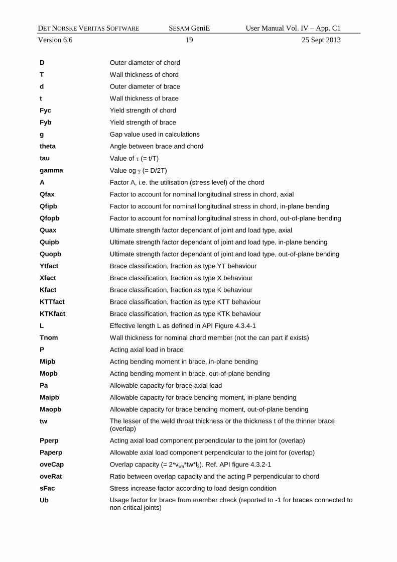
1.5.3 Tubular joint check API WSD 2002
The print of all available results inclusive intermediate data from the tubular joint check will report the
following:
Member Capacity model name (brace name)
Loadcase Name of load case/combination under consideration
Position Governing brace causing highest utilisation
Status Status regarding outcome of code check (OK or Failed)
UfTot Value of governing usage factor
Formula Reference to formula/check type causing the governing usage factor
SubCheck Which check causes this result, here API WSD joint capacity check
GeomCheck Status regarding any violation of geometric limitations:
- 0.2 < β < 1.0
uf411 Usage factor according to equation 4.1-1
uf4315a Usage factor according to equation 4.3.1-5a
uf4315b Usage factor according to equation 4.3.1-5b
uf4315bax Axial contribution to usage factor according to equation 4.3.1-5b
uf4315bmo Moment contribution to usage factor according to equation 4.3.1-5b
ufPperp Usage factor axial component perpendicular to chord for overlapping brace
beta Value of (= d/D), geometric limitation; 0.2 < < 1.
noTensile Control value regarding tensile strength (0 = OK, 1 = tensile strength not defined)
DET NORSKE VERITAS SOFTWARE SESAM GeniE User Manual Vol. IV – App. C1
Version 6.6 19 25 Sept 2013
D Outer diameter of chord
T Wall thickness of chord
d Outer diameter of brace
t Wall thickness of brace
Fyc Yield strength of chord
Fyb Yield strength of brace
g Gap value used in calculations
theta Angle between brace and chord
tau Value of (= t/T)
gamma Value og (= D/2T)
A Factor A, i.e. the utilisation (stress level) of the chord
Qfax Factor to account for nominal longitudinal stress in chord, axial
Qfipb Factor to account for nominal longitudinal stress in chord, in-plane bending
Qfopb Factor to account for nominal longitudinal stress in chord, out-of-plane bending
Quax Ultimate strength factor dependant of joint and load type, axial
Quipb Ultimate strength factor dependant of joint and load type, in-plane bending
Quopb Ultimate strength factor dependant of joint and load type, out-of-plane bending
Ytfact Brace classification, fraction as type YT behaviour
Xfact Brace classification, fraction as type X behaviour
Kfact Brace classification, fraction as type K behaviour
KTTfact Brace classification, fraction as type KTT behaviour
KTKfact Brace classification, fraction as type KTK behaviour
L Effective length L as defined in API Figure 4.3.4-1
Tnom Wall thickness for nominal chord member (not the can part if exists)
P Acting axial load in brace
Mipb Acting bending moment in brace, in-plane bending
Mopb Acting bending moment in brace, out-of-plane bending
Pa Allowable capacity for brace axial load
Maipb Allowable capacity for brace bending moment, in-plane bending
Maopb Allowable capacity for brace bending moment, out-of-plane bending
tw The lesser of the weld throat thickness or the thickness t of the thinner brace (overlap)
Pperp Acting axial load component perpendicular to the joint for (overlap)
Paperp Allowable axial load component perpendicular to the joint for (overlap)
oveCap Overlap capacity (= 2*vwa*tw*l2). Ref. API figure 4.3.2-1
oveRat Ratio between overlap capacity and the acting P perpendicular to chord
sFac Stress increase factor according to load design condition
Ub Usage factor for brace from member check (reported to -1 for braces connected to non-critical joints)

DET NORSKE VERITAS SOFTWARE SESAM GeniE User Manual Vol. IV – App. C1
Version 6.6 20 25 Sept 2013
1.5.4 Tubular joint check API WSD 2005
The print of all available results inclusive intermediate data from the joint check will report the following
data. Note that the usage factors uf435ax to ufshear are also reported for the case with respect to limit
geometrical values. The nomenclature is then similar to the “original”, but with _lim added.
Joint Capacity model name (joint name)
Loadcase Name of load case/combination under consideration
Member Governing brace causing highest utilisation
Status Status regarding outcome of code check (OK or Failed)
UfTot Value of governing usage factor
Formula Reference to formula/check type causing the governing usage factor
SubCheck Which check causes this result, here API WSD 2005 joint capacity check
GeomCheck Status regarding any violation of geometric limitations
uf435 Usage factor according to equation (4.3-5)
uf435ax Axial contribution to usage factor according to equation (4.3-5)
uf435mo Moment contribution to usage factor according to equation (4.3-5)
uf435mod Usage factor from through brace in overlapping joint, modified loads
uf435axmod Axial contribution in uf435mod
uf435momod Moment contribution in uf435mod
uf435ove Usage factor from overlap brace in overlapping joint, through brace as chord
uf435axove Axial contribution in uf435ove
uf435moove Moment contribution in uf435ove
ufshear Usage factor regarding shear capacity for oberlapping joint
beta Value of (= d/D), geometric limitation; 0.2 < < 1.
gamma Value og (= D/2T)
theta Angle between brace and chord
gap_D The gap/D ratio
ufipb usage factor, contribution from in-plane bending
ufopb usage factor, contribution from out-of-plane bending
P Design axial force in the brace member
Pa The joint design axial resistance (capacity)
Mipb Design in-plane bending moment in the brace member
Maipb Design in-plane bending resistance (capacity)
Mopb Design out-of-plane bending moment in the brace member
Maopb Design out-of-plane bending resistance (capacity)
Quaxial Ultimate strength factor dependant of joint and load type, axial
Quipb Ultimate strength factor dependant of joint and load type, in-plane bending
Quopb Ultimate strength factor dependant of joint and load type, out-of-plane bending
A The A factor used for calculating Qf

DET NORSKE VERITAS SOFTWARE SESAM GeniE User Manual Vol. IV – App. C1
Version 6.6 21 25 Sept 2013
Qfaxial Factor to account for nominal longitudinal stress in chord, axial
Qfipb Factor to account for nominal longitudinal stress in chord, in-plane bending
Qfopb Factor to account for nominal longitudinal stress in chord, out-of-plane bending
Ytfact Brace classification, fraction as type YT behaviour
Xfact Brace classification, fraction as type X behaviour
Kfact Brace classification, fraction as type K behaviour
KTTfact Brace classification, fraction as type KTT behaviour
KTKfact Brace classification, fraction as type KTK behaviour
CanFact reduction factor according to section 4.3.5 “Joints with Thickened Cans”
Fyc Yield strength of chord used in calculation
Fyb Yield strength of brace used in calculation
FS Factor of Safety
D Outer diameter of chord
T Wall thickness of chord
d Outer diameter of brace
t Wall thickness of brace
g Gap value used in calculations
----------------------------- o -----------------------------