gens (2010)_soil–environment interactions in geotechnical engineering
TRANSCRIPT

Gens, A. (2010). Geotechnique 60, No. 1, 3–74 [doi: 10.1680/geot.9.P.109]
3
Soil–environment interactions in geotechnical engineering
A. GENS�
The range of problems that geotechnical engineers mustface is increasing in complexity and scope. Often, com-plexity arises from the interaction between the soil andthe environment – the topic of this lecture. To deal withthis type of problem, the classical soil mechanics formula-tion is progressively generalised in order to incorporatethe effects of new phenomena and new variables on soilbehaviour. Recent advances in unsaturated soil mechanicsare presented first: it is shown that they provide aconsistent framework for understanding the engineeringbehaviour of unsaturated soils, and the effects of suctionand moisture changes. Building on those developments,soil behaviour is further explored by considering thermaleffects for two opposite cases: high temperatures,associated with the problem of storage and disposal ofhigh-level radioactive waste; and low temperatures inproblems of freezing ground. Finally, the lecture exam-ines some issues related to chemical effects on soils androcks, focusing in part on the subject of tunnelling insulphate-bearing rocks. In each case new environmentalvariables are identified, enhanced theoretical formulationsare established, and new or extended constitutive lawsare presented. Particular emphasis is placed on mechani-cal constitutive equations, as they are especially impor-tant in geotechnical engineering. The lecture includessummary accounts of a number of case histories thatillustrate the relevance and implications of the develop-ments described for geotechnical engineering practice.
KEYWORDS: constitutive relations; environmental engineering;partial saturation; snow, ice and frost; suction; temperatureeffects
La complexite et l’envergure des problemes que doiventaffronter et resoudre les ingenieurs geotechniciens aug-mentent constamment. Souvent, cette complexite tient al’interaction entre le sol et l’environnement, qui constituel’objet de la presente communication. Pour affronter cetype de problemes, on a generalise progressivement laformulation classique de la mecanique des sols, afind’incorporer les effets de variables et de phenomenesnouveaux sur le comportement du sol. On se penche, enpremier lieu, sur les progres realises recemment dans lamecanique de sols non satures. On demontre que ces solsconstituent un cadre regulier apportant des connaissancessur le comportement technique des sols non satures, etles effets de l’aspiration et des fluctuations de l’humidite.Sur la base de ces developpements, on poursuit l’explora-tion du comportement du sol en examinant les effetsthermiques dans deux cas opposes : les temperatureselevees dans le cadre du probleme du stockage et del’elimination de dechets radioactifs de haute activite, etles faibles temperatures dans les problemes de congela-tion du sol. Enfin, la communication examine certainesquestions relatives aux effets chimiques sur les sols et lesroches, en se concentrant en partie sur le sujet dupercement dans des roches sulfatees. On identifie, danschaque cas, de nouvelles variables environnementales ; enoutre, on etablit des formulations theoriques perfection-nees, et on presente des lois nouvelles ou renforcees surla constitution. On se penche en particulier sur desequations constitutives mecaniques, qui jouent un roleparticulierement important en ingenierie geotechnique.La communication comprend des comptes-rendus sur uncertain nombre d’etudes de cas illustrant la pertinence etles implications des developpements decrits pour la pra-tique de l’ingenierie geotechnique.
INTRODUCTIONGeotechnical engineering, in some form, must be a very oldhuman pursuit (Kerisel, 1987), but it is difficult to pinpointwith any degree of precision the start of soil mechanics, thescience that nowadays underlies a great deal of the disci-pline. There were certainly major contributions in the eight-eenth and nineteenth centuries, and of course one of thoseearly giants was William J. Macquorn Rankine, after whomthis lecture is named. However, it is commonly agreed thatmodern soil mechanics was initiated by Terzaghi (1925a,1925b), who was also responsible for many of its earlydevelopments. Because of the immediate success and rapidprogress of the subject, he could claim, in his address to theSecond International Conference on Soil Mechanics andFoundation Engineering, held in Rotterdam in 1948, that ‘In1936 Soil Mechanics had created what may be termed anideal of soil behaviour and had given the engineer a set oftheoretical concepts which covered all important aspects ofsoil behaviour.’ However, the scope of potential applicationsof soil mechanics is so wide, and the range of natural
materials is so extensive and varied, that it has often provednecessary to expand what can be loosely called classical soilmechanics in order to meet some of the challenges thatgeotechnical engineers face today and, even more, will facein the future. A somewhat arbitrary and certainly not com-prehensive list of geotechnical engineering problems that arelikely to require new approaches or, at least, extension ofthe classical ones is as follows: foundations on collapsingunsaturated soils; radioactive waste disposal; tunnelling insulphate-bearing materials; climate change effects on slopestability or on permafrost evolution; subsidence due to oiland gas extraction; containment of toxic or hazardous waste;dissolution, degradation and weathering of soils and rocks;CO2 sequestration: and the behaviour of methane hydrates.Some of those problems are considered in this lecture.
Often, soil behaviour related to such problems is referredto as ‘problematic behaviour’, and the soils associated withthem as ‘problematic soils’. However, in this context it isworth quoting a former Rankine lecturer (and also my PhDsupervisor), P. R. Vaughan, who once wrote:
‘Classical soil mechanics has evolved around a few sim-plified models which do not fit the properties of most realsoils sufficiently for useful and safe predictions to be made. . . Since we cannot change the soil to fit the soil mechanics,
Discussion on this paper closes on 1 June 2010; for further detailssee p. ii.� Technical University of Catalonia, Barcelona, Spain.
perhaps we should change the soil mechanics to fit the soil.The theory which fails to fit their behaviour is problematic,not the soil.’ (Vaughan, 1999)
Indeed, many of the soil mechanics developments in thelast few decades can be seen as an attempt to modify theclassical approaches to fit real soil behaviour. It must beadded that, often, it is not only the soil itself that may seemproblematic; complexity also arises from the interactionbetween the soil and the environment—the topic of thislecture. The term ‘environment’ is used here in a rather all-encompassing way, perhaps somewhat different from theusual one. Taken to the limit, even pore pressure should beviewed as an environmental variable.
Some landmarks of classical soil mechanicsBefore going beyond classical soil mechanics, it is worth-
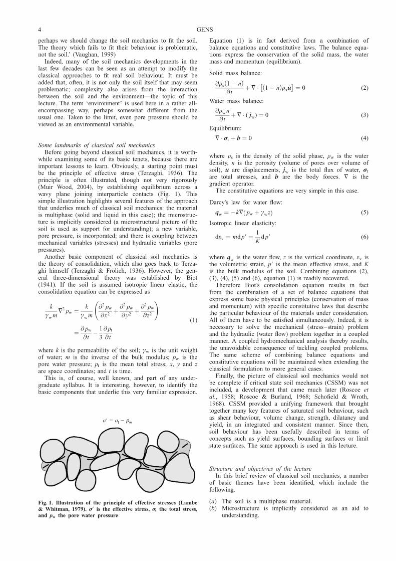
while examining some of its basic tenets, because there areimportant lessons to learn. Obviously, a starting point mustbe the principle of effective stress (Terzaghi, 1936). Theprinciple is often illustrated, though not very rigorously(Muir Wood, 2004), by establishing equilibrium across awavy plane joining interparticle contacts (Fig. 1). Thissimple illustration highlights several features of the approachthat underlies much of classical soil mechanics: the materialis multiphase (solid and liquid in this case); the microstruc-ture is implicitly considered (a microstructural picture of thesoil is used as support for understanding); a new variable,pore pressure, is incorporated; and there is coupling betweenmechanical variables (stresses) and hydraulic variables (porepressures).
Another basic component of classical soil mechanics isthe theory of consolidation, which also goes back to Terza-ghi himself (Terzaghi & Frolich, 1936). However, the gen-eral three-dimensional theory was established by Biot(1941). If the soil is assumed isotropic linear elastic, theconsolidation equation can be expressed as
k
ªw m=2 pw ¼ k
ªw m
@2 pw
@x2þ @2 pw
@ y2þ @2 pw
@z2
!
¼ @ pw
@ t� 1
3
@ pt
@ t
(1)
where k is the permeability of the soil; ªw is the unit weightof water; m is the inverse of the bulk modulus; pw is thepore water pressure; pt is the mean total stress; x, y and zare space coordinates; and t is time.
This is, of course, well known, and part of any under-graduate syllabus. It is interesting, however, to identify thebasic components that underlie this very familiar expression.
Equation (1) is in fact derived from a combination ofbalance equations and constitutive laws. The balance equa-tions express the conservation of the solid mass, the watermass and momentum (equilibrium).
Solid mass balance:
@rs 1 � nð Þ@ t
þ = � 1 � nð Þrs _u� �
¼ 0 (2)
Water mass balance:
@rw n
@ tþ = � ( jw) ¼ 0 (3)
Equilibrium:
= � �t þ b ¼ 0 (4)
where rs is the density of the solid phase, rw is the waterdensity, n is the porosity (volume of pores over volume ofsoil), u are displacements, jw is the total flux of water, �t
are total stresses, and b are the body forces. = is thegradient operator.
The constitutive equations are very simple in this case.
Darcy’s law for water flow:
qw ¼ �k= pw þ ªwzð Þ (5)
Isotropic linear elasticity:
d�v ¼ md p9 ¼ 1
Kd p9 (6)
where qw is the water flow, z is the vertical coordinate, �v isthe volumetric strain, p9 is the mean effective stress, and Kis the bulk modulus of the soil. Combining equations (2),(3), (4), (5) and (6), equation (1) is readily recovered.
Therefore Biot’s consolidation equation results in factfrom the combination of a set of balance equations thatexpress some basic physical principles (conservation of massand momentum) with specific constitutive laws that describethe particular behaviour of the materials under consideration.All of them have to be satisfied simultaneously. Indeed, it isnecessary to solve the mechanical (stress–strain) problemand the hydraulic (water flow) problem together in a coupledmanner. A coupled hydromechanical analysis thereby results,the unavoidable consequence of tackling coupled problems.The same scheme of combining balance equations andconstitutive equations will be maintained when extending theclassical formulation to more general cases.
Finally, the picture of classical soil mechanics would notbe complete if critical state soil mechanics (CSSM) was notincluded, a development that came much later (Roscoe etal., 1958; Roscoe & Burland, 1968; Schofield & Wroth,1968). CSSM provided a unifying framework that broughttogether many key features of saturated soil behaviour, suchas shear behaviour, volume change, strength, dilatancy andyield, in an integrated and consistent manner. Since then,soil behaviour has been usefully described in terms ofconcepts such as yield surfaces, bounding surfaces or limitstate surfaces. The same approach is used in this lecture.
Structure and objectives of the lectureIn this brief review of classical soil mechanics, a number
of basic themes have been identified, which include thefollowing.
(a) The soil is a multiphase material.(b) Microstructure is implicitly considered as an aid to
understanding.
σ σ� � �t wp
Fig. 1. Illustration of the principle of effective stresses (Lambe& Whitman, 1979). �9 is the effective stress, �t the total stress,and pw the pore water pressure
4 GENS

(c) New additional variables are required to fully describesoil behaviour—pore pressure in this case.
(d ) The relevant phenomena are often coupled phenomena,leading to coupled analysis.
(e) Finally, it is possible to employ unifying frameworks ofthe critical state type.
The objective of the lecture is to try to extend and general-ise classical soil mechanics to incorporate new types of soilbehaviour, and the effects of new environmental variables.Three partially overlapping topics are discussed. Unsaturatedsoils, a subject closely associated with the effects of suction,are considered first. Then thermal effects are examined,taking into account two extreme cases: high temperatures,associated with the problem of storage and disposal of high-level radioactive waste; and low temperature in problems offreezing ground. Finally, the lecture explores some issuesrelated to chemical effects on soils and rocks, focusing, tosome extent, on the subject of tunnelling in sulphate-bearingrocks.
For consistency, the required developments should becongruent with the underlying themes of classical soil mech-anics. Accordingly, for each of those topics, it will benecessary to
(a) identify additional (environmental) variables(b) establish more general theoretical formulations that may
require additional or enhanced balance equations(c) propose new or extended constitutive equations, paying
special attention to the mechanical constitutive laws,which are often the most relevant ones for geotechnicalengineering.
The aims are both understanding and application to practice.This requires soil behaviour, constitutive modelling, analysis,and field observations to be brought together as required.The lecture includes summaries of case histories that illus-trate the transfer of the developments described to engineer-ing practice.
UNSATURATED SOILS: SUCTION AND COUPLEDFORMULATIONGeneral
Unsaturated soils are simply soils in which the pore spaceis occupied by more than a fluid, normally liquid and gas(Fig. 2). A basic variable characterising this type of soil isthe liquid degree of saturation (often abbreviated to degreeof saturation), Sl, which is the proportion of the pores
occupied by the liquid phase. The gas degree of saturation,Sg, can be defined in a similar way; obviously, Sl ¼ 1 � Sg.
Unsaturated soils give rise to very characteristic types ofgeotechnical problem. For instance, it is well known thatslopes involving unsaturated soils are prone to failure duringrainy periods, owing to the loss of strength associated withthe increase of degree of saturation. Fig. 3 shows anexample, the Kwun Lung Lau landslide, which occurred inHong Kong on 23 July 1994 (Wong & Ho, 1997). It resultedin five fatalities, and was closely related to the saturationand weakening of the soil mass arising from heavy rainfallthat occurred in the 48 h before the landslide, when aprecipitation of 547 mm was recorded nearby. Interestingly,however, rainfall had largely ceased about 10 h before thefailure. The ground was made of a rather permeable filloverlying partially weathered volcanic tuff. The forensicinvestigation concluded that the landslide was most likely tohave been caused by the ingress of a large volume of wateras a result of leakage from underground services (stormwaterpipes and a sewer), bringing about an increase of degree ofsaturation and a reduction of the shear strength of theground (Wong & Ho, 1997).
A different but also typical problem involving unsaturatedsoils is the damage to structures caused by the collapse ofthe foundation soil due to wetting. In spite of the use of theterm collapse, this phenomenon does not involve failure, butthe compression of the soil due to an increase in degree ofsaturation. Often, poorly compacted fills are involved(Charles, 2008), but collapse behaviour is also observed innatural materials. An interesting example of foundationcollapse occurring in natural soil took place in Via Settem-brini, Naples, on 15 September 2001, as illustrated in Fig. 4(Viggiani, 2007, personal communication). The foundationsoil was composed of a layer of pyroclasts overlying a tuff(Fig. 5). In spite of the loose character of the pyroclasticsoil, the foundation had remained stable for a long time,until the material was wetted by water coming throughdisused ancient wells that were connected to a blocked deep-water cistern (Pellegrino, 2005). A heavy rainstorm resultingin 130–160 mm rainfall in 3 h caused the water to overflowthe wells and saturate parts of the foundation soils (Fig. 5).Maximum settlements of the order of 200 mm were meas-ured from the start of monitoring, some time after the event.It was estimated that the observed collapse settlement corres-ponded to a water table rise of about 12 m (Feola et al.,2004).
Clearly, a proper account of the behaviour of unsaturatedsoils must incorporate, among other features, these basiceffects of wetting on strength and deformation.
Liquid
SolidGas
Fig. 2. Scheme of an unsaturated soil
Fig. 3. Kwun Lung Lau landslide, Hong Kong (photographfrom http://hkss.cedd.gov.hk/hkss/eng/photo_gallery/)
SOIL–ENVIRONMENT INTERACTIONS IN GEOTECHNICAL ENGINEERING 5

An additional variable: suctionIt has long been recognised (e.g. Croney, 1952; Burland
& Ridley, 1996) that an adequate understanding of thebehaviour of unsaturated soils requires the proper considera-tion of suction. In this context it is useful to recall thedefinition of the soil–water (total) potential: the amount ofwork that must be done per unit mass of pure water in orderto transport reversibly and isothermally an infinitesimalquantity of water from a reservoir of pure water at aspecified elevation and gas pressure to the soil point underconsideration. It can be readily verified that the work done
corresponds to a variation in free energy per unit mass (e.g.Aitchison et al., 1965). Potential has therefore units ofenergy per unit mass (L2T�2; J/kg). Total potential controlsthe flow of water: water flows from regions of high waterpotential towards regions of lower water potential. If there isno flow between two masses of water, it necessarily meansthat the water potentials are the same in the two zones.
In 1965 a review panel in the Symposium on MoistureEquilibrium and Moisture Changes in Soils Beneath CoveredAreas (Aitchison et al., 1965) proposed a division of thetotal potential into four different components: gravitationalpotential, łg; gas pressure potential, łp; matric potential,łm; and osmotic potential, ło.
ł ¼ łg þ łp þ łm þ ło (7)
Although there is a certain degree of arbitrariness in thisdivision, it has proved very useful in the context of geo-technical engineering. The gravity potential is given by thedifference in elevations; the gas pressure potential is relatedto the applied gas pressure; osmotic potential depends ondifferences in solute concentrations (across a semi-permeablemembrane); and the matric potential is related to the inter-action between liquid and solid. In soil science, gas pressurepotential is generally replaced by overburden potential, amore general concept. Although this division into compo-nents is useful for a better understanding, it should bestressed that the only parameter controlling the mass transferof water is the sum of all four components.
With respect to the mechanical behaviour of unsaturatedsoils, the situation is more complex, as it is by no meanstrue that all potential components have a similar effect. Infact, it is obvious that gravitational potential does not affectmechanical behaviour in any significant way. In addition,experimental results (Fredlund & Morgenstern, 1977;Tarantino et al., 2000) and some theoretical considerationsfor soils with incompressible grains (Alcoverro, 2003) indi-cate that the gas pressure potential should have no influenceon mechanical behaviour either. Therefore only osmoticpotential and matric potential, the internal components ofpotential, affect the mechanical response of unsaturated soilsin any significant way. Again, there is no reason for the twopotential components to have equivalent effects. In fact, itcan be easily checked experimentally that their influences onmechanical behaviour are quite different, and depend on thetype of soil (Aitchison, 1965). Osmotic effects require somekind of semi-permeable membrane. Because of the smallpore sizes in clays and the electric fields within them, clayeymaterials may in some cases exhibit membrane propertiesrestricting, to some degree, the passage of certain chemicalcomponents through the soil (Mitchell, 1991). In non-activesoils, osmotic effects are likely to be negligible. Conse-quently, attention is focused mainly on matric potential.
As an alternative to potential, the concept of suction isoften used. If energy (or work) is considered per unitvolume (instead of per unit mass), the resulting variable iscalled suction, and it is expressed in terms of pressure(ML�1T�2; kN/m2), with a sign change to avoid using nega-tive values. Thus matric suction is denoted by s and osmoticsuction by so. The sum of matric and osmotic suctions isoften called total suction, st ¼ s + so. Total suction is relatedto relative humidity (RH) via Kelvin’s law,
RH ¼ pv
pvð Þ0¼
Łwg
Łwg
� �0
¼ exp�st Mw
RTrw
� � (8)
Fig. 4. Collapse of a foundation on loose pyroclastic soil in ViaSettembrini, Naples (Viggiani, 2007, personal communication)
Wells
Pyroclasts
TuffCanal
Reservoir
Water
Fig. 5. Wetting of the foundation soil due to overflow of disusedwells. The saturation of part of the pyroclastic layer causedcollapse settlements in the foundation of a building in ViaSettembrini, Naples (Pellegrino, 2005)
6 GENS
where pv is the partial vapour pressure; (pv)0 is the equili-brium vapour pressure at the same temperature and zerosuction; Łw
g is the vapour concentration; (Łwg )0 is the refer-
ence vapour concentration at the same temperature; Mw isthe molecular mass of water (18.016 kg/kmol); R is theuniversal gas constant (8.314 J/(mol K)); and T is the abso-lute temperature in kelvin.
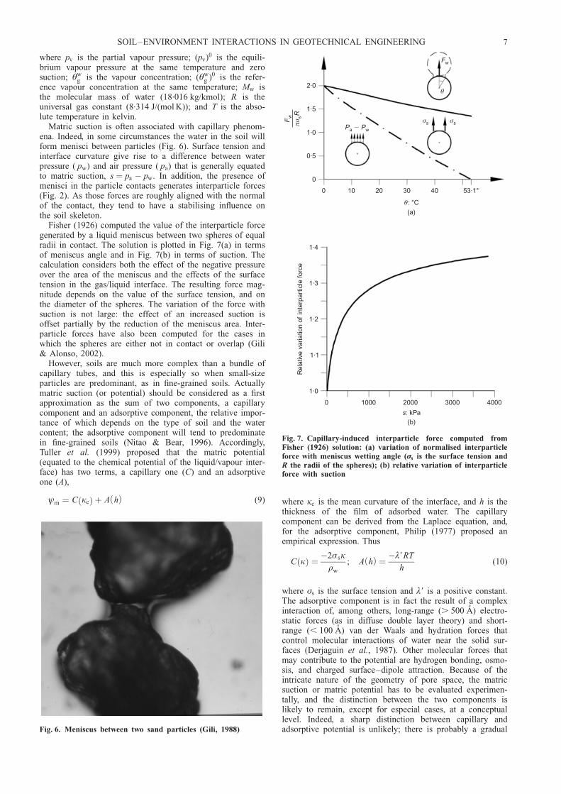
Matric suction is often associated with capillary phenom-ena. Indeed, in some circumstances the water in the soil willform menisci between particles (Fig. 6). Surface tension andinterface curvature give rise to a difference between waterpressure ( pw) and air pressure ( pa) that is generally equatedto matric suction, s ¼ pa � pw. In addition, the presence ofmenisci in the particle contacts generates interparticle forces(Fig. 2). As those forces are roughly aligned with the normalof the contact, they tend to have a stabilising influence onthe soil skeleton.
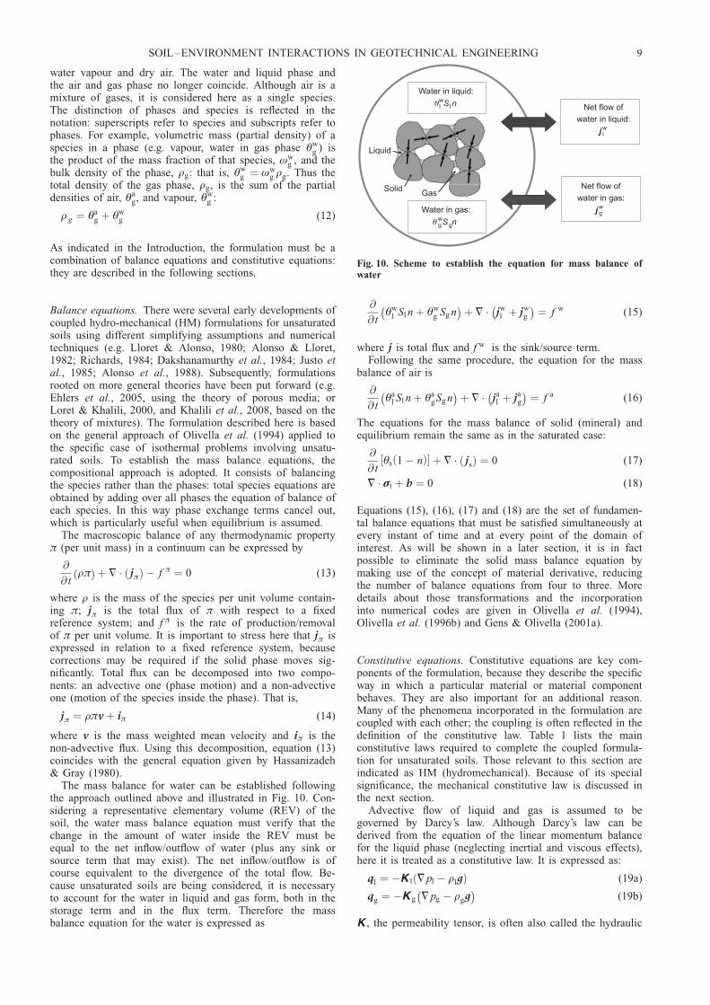
Fisher (1926) computed the value of the interparticle forcegenerated by a liquid meniscus between two spheres of equalradii in contact. The solution is plotted in Fig. 7(a) in termsof meniscus angle and in Fig. 7(b) in terms of suction. Thecalculation considers both the effect of the negative pressureover the area of the meniscus and the effects of the surfacetension in the gas/liquid interface. The resulting force mag-nitude depends on the value of the surface tension, and onthe diameter of the spheres. The variation of the force withsuction is not large: the effect of an increased suction isoffset partially by the reduction of the meniscus area. Inter-particle forces have also been computed for the cases inwhich the spheres are either not in contact or overlap (Gili& Alonso, 2002).
However, soils are much more complex than a bundle ofcapillary tubes, and this is especially so when small-sizeparticles are predominant, as in fine-grained soils. Actuallymatric suction (or potential) should be considered as a firstapproximation as the sum of two components, a capillarycomponent and an adsorptive component, the relative impor-tance of which depends on the type of soil and the watercontent; the adsorptive component will tend to predominatein fine-grained soils (Nitao & Bear, 1996). Accordingly,Tuller et al. (1999) proposed that the matric potential(equated to the chemical potential of the liquid/vapour inter-face) has two terms, a capillary one (C) and an adsorptiveone (A),
łm ¼ C kcð Þ þ A hð Þ (9) where kc is the mean curvature of the interface, and h is thethickness of the film of adsorbed water. The capillarycomponent can be derived from the Laplace equation, and,for the adsorptive component, Philip (1977) proposed anempirical expression. Thus
C kð Þ ¼ �2� skrw
; A hð Þ ¼ �º9RT
h(10)
where �s is the surface tension and º9 is a positive constant.The adsorptive component is in fact the result of a complexinteraction of, among others, long-range (. 500 A) electro-static forces (as in diffuse double layer theory) and short-range (, 100 A) van der Waals and hydration forces thatcontrol molecular interactions of water near the solid sur-faces (Derjaguin et al., 1987). Other molecular forces thatmay contribute to the potential are hydrogen bonding, osmo-sis, and charged surface–dipole attraction. Because of theintricate nature of the geometry of pore space, the matricsuction or matric potential has to be evaluated experimen-tally, and the distinction between the two components islikely to remain, except for especial cases, at a conceptuallevel. Indeed, a sharp distinction between capillary andadsorptive potential is unlikely; there is probably a gradualFig. 6. Meniscus between two sand particles (Gili, 1988)
2·0
1·5
1·0
0·5
0
0 10 20 30 40 53·1°
θ: °C
(a)
P Pa w�σs σs
θ
Fw
F
Rw sπ
σ
1·4
1·3
1·2
1·1
1·0
0 1000 2000 3000 4000
s: kPa(b)
Rel
ativ
e va
riatio
n of
inte
rpar
ticle
forc
e
Fig. 7. Capillary-induced interparticle force computed fromFisher (1926) solution: (a) variation of normalised interparticleforce with meniscus wetting angle (�s is the surface tension andR the radii of the spheres); (b) relative variation of interparticleforce with suction
SOIL–ENVIRONMENT INTERACTIONS IN GEOTECHNICAL ENGINEERING 7

transition as the distance to the solid particle surfacereduces. Capillary potential will tend to dominate in granularsoils, and in soils with high degrees of saturation, whereasthe adsorptive potential will be more significant in clayeysoils, especially at low water contents.
Partly for historical reasons it is usual to express matricsuction, over the full range of degrees of saturation, in termsof pressure difference (s ¼ pa � pw) as if the capillary modelwas valid. However, it is more appropriate to think of matricsuction as a variable that expresses quantitatively the degreeof attachment of the liquid to the solid phase that resultsfrom the general solid/water/interface interaction. This per-spective should help to dispel the misgivings that are some-times expressed about the physical meaning of negativepressures reaching values of hundreds of MPa. Those largesuction values refer to the very large potential of the waterimmediately adjacent to the solid surface, but they shouldnot be viewed as pressures in the conventional bulk thermo-dynamic sense. Care should be taken, therefore, not toequate automatically all matric suction effects to capillaryphenomena: in some instances the capillary model is quiteunrealistic.
The fact that the two components of matric suction arelumped together in a single variable, and that, in addition,they are difficult to separate experimentally, should not leadto the conclusion that their effects on mechanical behaviourare equivalent. Actually, such effects should depend on therelative importance of each of the two components, andthereby on the type of soil being examined. Indeed, much ofthe variability of the soil response to matric suction changesis likely to be related to the different effects of the capillaryand adsorptive components, and to their varying proportions.An extensive discussion on the same issues has been pre-sented recently (Baker & Frydman, 2009).
If matric suction is basically related to molecular forces,it should be largely independent of gravitational potential. Itis possible to compute a capillary length of water k�1
c belowwhich gravitational effects should be negligible (De Genneset al., 2004). At normal temperatures
k�1c ¼
ffiffiffiffiffiffiffiffiffiffiffiffiffiffiffiffi� s=rw g
p� 2:7 mm (11)
where g is the gravity acceleration. Since the pores of mostsoils are well below this capillary length, matric suctionshould be independent of gravitational forces.
The performance of a series of centrifuge tests on unsatu-rated soils within the framework of the MUSE (Mechanicsof Unsaturated Soils for Engineering) Marie Curie frame-work has provided an opportunity to check this conclusion(Casini et al., 2009). The tests were conducted in the LCPCcentrifuge at Nantes (France). The material tested is Jossignysilt (wL ¼ 32.3%, IP ¼ 15.3%), statically compacted to adry unit weight ªd around 14.5 kN/m3 and a water content wof about 13%, The sample was placed in a cylindricalcontainer 300 mm in diameter and 300 mm long (Fig. 8).Two sets of tensiometers, provided by ENPC-CERMES(Paris) and by Durham University, were installed at differentheights on opposite sides of the sample. Here, only thereadings of the tensiometers during acceleration and decel-eration are examined. Fig. 9(a) shows the evolution of porepressures measured in one of the tensiometers sets(CERMES) during the acceleration stage. Initial pore pres-sures are negative, corresponding to the suctions set upduring compaction. There is some response of the tensi-ometers during the 7 min acceleration from 1g to 50g, butthis is probably due to the reaction of the measurementdevices: it is noteworthy that, at the end of the acceleration,suction values are very similar to the initial ones. Certainly,the increase of gravitational forces by 50 times has not made
a significant impact on the measured suction. Of course, inthe longer term there will be changes in pore pressures, butthey correspond to the consolidation process associated withthe new stress state in the specimen. The observations areeven more clear-cut during the deceleration stage from 50gto 1g, which occurs in just over a minute. As Fig. 9(b)shows, the pore pressure readings do not react at all to thechange of centrifuge acceleration, indicating the insensitivityof matric suction to gravitational forces.
Enhanced hydromechanical coupled formulation forunsaturated soils
To develop an appropriate coupled formulation for unsatu-rated soils, it is convenient to make a distinction betweenphases and species. It is postulated that the porous mediumis composed of three species—mineral (–), water (w) andair (a)—distributed in three phases: solid (s), liquid (l) andgas (g). In this case it is assumed that the mineral speciesand the solid phase coincide. However, the liquid phase maycontain dissolved air, and the gas phase is a mixture of
T1
T2
T3
300 mm
300
mm
50g
Fig. 8. Specimen of compacted unsaturated Jossigny silt fortesting in the LCPC centrifuge
0
�100
�200W
ate
r pr
essu
re: k
Pa
7 min Acceleration60
40
20
0
Acc
eler
atio
n:g
0·4500·4450·4350·430 0·440
Time: days(a)
T1
T2
T3
0
�100
�200
Wa
ter
pres
sure
: kP
a
1·1 min
Acceleration60
40
20
0
Acc
eler
atio
n:g
0·6600·6580·6520·650 0·654
Time: days(b)
T1
T2
T3
0·656
Fig. 9. Evolution of pore pressures in a centrifuge test onJossigny silt: (a) acceleration stage; (b) deceleration stage
8 GENS
water vapour and dry air. The water and liquid phase andthe air and gas phase no longer coincide. Although air is amixture of gases, it is considered here as a single species.The distinction of phases and species is reflected in thenotation: superscripts refer to species and subscripts refer tophases. For example, volumetric mass (partial density) of aspecies in a phase (e.g. vapour, water in gas phase Łw
g ) isthe product of the mass fraction of that species, øw
g , and thebulk density of the phase, rg: that is, Łw
g ¼ øwg rg. Thus the
total density of the gas phase, rg, is the sum of the partialdensities of air, Ła
g, and vapour, Łwg :
r g ¼ Łag þ Łw
g (12)
As indicated in the Introduction, the formulation must be acombination of balance equations and constitutive equations:they are described in the following sections.
Balance equations. There were several early developments ofcoupled hydro-mechanical (HM) formulations for unsaturatedsoils using different simplifying assumptions and numericaltechniques (e.g. Lloret & Alonso, 1980; Alonso & Lloret,1982; Richards, 1984; Dakshanamurthy et al., 1984; Justo etal., 1985; Alonso et al., 1988). Subsequently, formulationsrooted on more general theories have been put forward (e.g.Ehlers et al., 2005, using the theory of porous media; orLoret & Khalili, 2000, and Khalili et al., 2008, based on thetheory of mixtures). The formulation described here is basedon the general approach of Olivella et al. (1994) applied tothe specific case of isothermal problems involving unsatu-rated soils. To establish the mass balance equations, thecompositional approach is adopted. It consists of balancingthe species rather than the phases: total species equations areobtained by adding over all phases the equation of balance ofeach species. In this way phase exchange terms cancel out,which is particularly useful when equilibrium is assumed.
The macroscopic balance of any thermodynamic property� (per unit mass) in a continuum can be expressed by
@
@ tr�ð Þ þ = � j�ð Þ � f � ¼ 0 (13)
where r is the mass of the species per unit volume contain-ing �; j� is the total flux of � with respect to a fixedreference system; and f � is the rate of production/removalof � per unit volume. It is important to stress here that j� isexpressed in relation to a fixed reference system, becausecorrections may be required if the solid phase moves sig-nificantly. Total flux can be decomposed into two compo-nents: an advective one (phase motion) and a non-advectiveone (motion of the species inside the phase). That is,
j� ¼ r�vþ i� (14)
where v is the mass weighted mean velocity and i� is thenon-advective flux. Using this decomposition, equation (13)coincides with the general equation given by Hassanizadeh& Gray (1980).
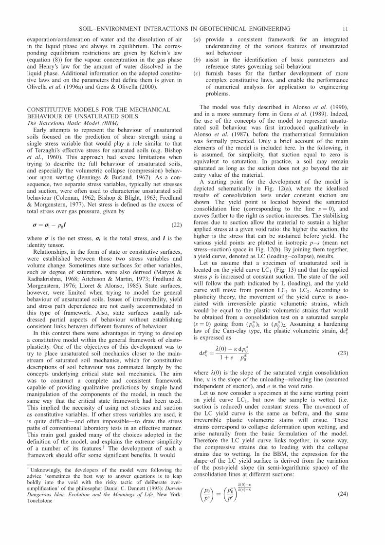
The mass balance for water can be established followingthe approach outlined above and illustrated in Fig. 10. Con-sidering a representative elementary volume (REV) of thesoil, the water mass balance equation must verify that thechange in the amount of water inside the REV must beequal to the net inflow/outflow of water (plus any sink orsource term that may exist). The net inflow/outflow is ofcourse equivalent to the divergence of the total flow. Be-cause unsaturated soils are being considered, it is necessaryto account for the water in liquid and gas form, both in thestorage term and in the flux term. Therefore the massbalance equation for the water is expressed as
@
@ tŁw
l Sl n þ Łwg Sg n
� �þ = � jwl þ jwg
� �¼ f w (15)
where j is total flux and f w is the sink/source term.Following the same procedure, the equation for the mass
balance of air is
@
@ tŁa
l Sl n þ ŁagSg n
� �þ = � jal þ jag
� �¼ f a (16)
The equations for the mass balance of solid (mineral) andequilibrium remain the same as in the saturated case:
@
@ tŁs 1 � nð Þ½ � þ = � jsð Þ ¼ 0 (17)
= � �t þ b ¼ 0 (18)
Equations (15), (16), (17) and (18) are the set of fundamen-tal balance equations that must be satisfied simultaneously atevery instant of time and at every point of the domain ofinterest. As will be shown in a later section, it is in factpossible to eliminate the solid mass balance equation bymaking use of the concept of material derivative, reducingthe number of balance equations from four to three. Moredetails about those transformations and the incorporationinto numerical codes are given in Olivella et al. (1994),Olivella et al. (1996b) and Gens & Olivella (2001a).
Constitutive equations. Constitutive equations are key com-ponents of the formulation, because they describe the specificway in which a particular material or material componentbehaves. They are also important for an additional reason.Many of the phenomena incorporated in the formulation arecoupled with each other; the coupling is often reflected in thedefinition of the constitutive law. Table 1 lists the mainconstitutive laws required to complete the coupled formula-tion for unsaturated soils. Those relevant to this section areindicated as HM (hydromechanical). Because of its specialsignificance, the mechanical constitutive law is discussed inthe next section.
Advective flow of liquid and gas is assumed to begoverned by Darcy’s law. Although Darcy’s law can bederived from the equation of the linear momentum balancefor the liquid phase (neglecting inertial and viscous effects),here it is treated as a constitutive law. It is expressed as:
ql ¼ �K l =pl � rlgð Þ (19a)
qg ¼ �K g =pg � rgg� �
(19b)
K , the permeability tensor, is often also called the hydraulic
Water in liquid:
θwl lS n Net flow of
water in liquid:
j wl
Net flow of
water in gas:
j wgWater in gas:
θ wg gS n
GasSolid
Liquid
Fig. 10. Scheme to establish the equation for mass balance ofwater
SOIL–ENVIRONMENT INTERACTIONS IN GEOTECHNICAL ENGINEERING 9

conductivity, for consistency with other conductivity para-meters. The permeability (or hydraulic conductivity) tensorhas a certain structure, given by
K ¼ k
�Æ
� �kr (20)
where k is the intrinsic permeability, � is the fluid viscosity,and kr is the relative permeability. Intrinsic permeability isnot a constant; it depends on porosity, pore size and porestructure. Relative permeability depends on suction (or de-gree of saturation), and may vary enormously, depending onthe saturation state of the soil. As an example, Fig. 11 shows
the variation of relative permeability for two rather coarseHong Kong soils: a colluvium, and a residual soil ofdecomposed granite (Fredlund & Rahardjo, 1993). The rel-ative permeability (and therefore the hydraulic conductivity)reduces by several orders of magnitude over rather modestincreases of suction. This variation of permeability withsuction controls, for instance, the infiltration of water intohill slopes, with the obvious subsequent influence on stabi-lity. Indeed, in flow through unsaturated soils, the variationof relative permeability is often a dominant feature of theproblem.
The relationship between suction and degree of saturation(or water content) is defined by the retention curve (or soil-water characteristic curve, SWCC). It exhibits hystereticbehaviour, and is strongly dependent on the pore sizedistribution of the soil. It is also a very important relation-ship for flow in unsaturated soils, because it largely controlsthe storage capacity of the soil. Many different analyticalexpressions have been proposed for this constitutive law(Fredlund, 2006).
The diffusive flows of species inside a phase (vapour inthe gas phase, dissolved air in the liquid phase) are governedby Fick’s law: gradients of concentration are the drivingthermodynamic force for this type of flow. For instance, inthe case of vapour diffusion, the constitutive law can bewritten as
iwg ¼ �Dwg =ø
wg
¼ � rg nSg�DwmI þ rgD9g
� �=øw
g
(21)
where iwg is the diffusive (non advective) flow of vapour, Dwg
is the vapour dispersion tensor, � is tortuosity, Dwm is the
diffusion coefficient of vapour in air, and D9g is the mechan-ical dispersion tensor. Tortuosity is an empirical parameterthat is intended to account for the fact that vapour diffusiontakes place inside a porous medium.
Finally, liquid density depends on liquid pressure in aquasi-linear manner, defined by the corresponding bulkmodulus Kl. The bulk modulus of water, usually the domi-nant species in the liquid phase is about 2.2 3 106 MPa,although it increases at very high pressures. In contrast, thegas density variation is non-linear with respect to pressure,in accordance with the ideal gas law pgV ¼ nm RT, where Vis volume and nm is the number of moles.
In this particular formulation it is also assumed that
Table 1. Constitutive equations and equilibrium restrictions
Phenomena Equation Variable Formulation
Constitutive equations
Advective flow of liquid and gas Darcy’s law ql, qg HM, THM, THMCWater absorption/desorption Retention curve Sl, Sg HM, THM, THMC
Diffusive flow of vapour and dissolved air Fick’s law iwg , ial HM, THM, THMCStress–strain behaviour Mechanical constitutive model � HM, THM, THMCSolid density variation Phase density relationship rs HM, THM, THMCLiquid density variation Phase density relationship rl HM, THM, THMCGas density variation Ideal gas law rg HM, THM, THMCHeat conduction Fourier’s law ic THM, THMCKinetic-controlled chemical reactions Chemical kinetics Ri THMC
Equilibrium restrictions
Evaporation/condensation of water Kelvin’s law øwg HM, THM, THMC
Dissolution of air in water Henry’s law øal HM, THM, THMC
Equilibrium chemical reaction Chemical equilibrium Xi THMC
HM, hydromechanical; THM, thermo-hydromechanical; THMC, thermo-hydromechanical-chemical.
10�4
10�5
10�6
10�7
10�8
10�9
10�10
10�11
10�12
10�13
Coe
ffic
ient
of
perm
eabi
lity,
: m/s
k w
Colluvium
n
Decomposedgranite
100 101 102 103
Matric suction, ( ): kPau ua w�
Fig. 11. Variation of relative permeability with suction for twoHong Kong soils (Fredlund & Rahardjo, 1993)
10 GENS
evaporation/condensation of water and the dissolution of airin the liquid phase are always in equilibrium. The corres-ponding equilibrium restrictions are given by Kelvin’s law(equation (8)) for the vapour concentration in the gas phaseand Henry’s law for the amount of water dissolved in theliquid phase. Additional information on the adopted constitu-tive laws and on the parameters that define them is given inOlivella et al. (1996a) and Gens & Olivella (2000).
CONSTITUTIVE MODELS FOR THE MECHANICALBEHAVIOUR OF UNSATURATED SOILSThe Barcelona Basic Model (BBM)
Early attempts to represent the behaviour of unsaturatedsoils focused on the prediction of shear strength using asingle stress variable that would play a role similar to thatof Terzaghi’s effective stress for saturated soils (e.g. Bishopet al., 1960). This approach had severe limitations whentrying to describe the full behaviour of unsaturated soils,and especially the volumetric collapse (compression) behav-iour upon wetting (Jennings & Burland, 1962). As a con-sequence, two separate stress variables, typically net stressesand suction, were often used to characterise unsaturated soilbehaviour (Coleman, 1962; Bishop & Blight, 1963; Fredlund& Morgenstern, 1977). Net stress is defined as the excess oftotal stress over gas pressure, given by
� ¼ �t � pgI (22)
where � is the net stress, �t is the total stress, and I is theidentity tensor.
Relationships, in the form of state or constitutive surfaces,were established between those two stress variables andvolume change. Sometimes state surfaces for other variables,such as degree of saturation, were also derived (Matyas &Radhakrishna, 1968; Aitchison & Martin, 1973; Fredlund &Morgenstern, 1976; Lloret & Alonso, 1985). State surfaces,however, were limited when trying to model the generalbehaviour of unsaturated soils. Issues of irreversibility, yieldand stress path dependence are not easily accommodated inthis type of framework. Also, state surfaces usually ad-dressed partial aspects of behaviour without establishingconsistent links between different features of behaviour.
In this context there were advantages in trying to developa constitutive model within the general framework of elasto-plasticity. One of the objectives of this development was totry to place unsaturated soil mechanics closer to the main-stream of saturated soil mechanics, which for constitutivedescriptions of soil behaviour was dominated largely by theconcepts underlying critical state soil mechanics. The aimwas to construct a complete and consistent frameworkcapable of providing qualitative predictions by simple handmanipulation of the components of the model, in much thesame way that the critical state framework had been used.This implied the necessity of using net stresses and suctionas constitutive variables. If other stress variables are used, itis quite difficult—and often impossible—to draw the stresspaths of conventional laboratory tests in an effective manner.This main goal guided many of the choices adopted in thedefinition of the model, and explains the extreme simplicityof a number of its features.y The development of such aframework should offer some significant benefits. It would
(a) provide a consistent framework for an integratedunderstanding of the various features of unsaturatedsoil behaviour
(b) assist in the identification of basic parameters andreference states governing soil behaviour
(c) furnish bases for the further development of morecomplex constitutive laws, and enable the performanceof numerical analysis for application to engineeringproblems.
The model was fully described in Alonso et al. (1990),and in a more summary form in Gens et al. (1989). Indeed,the use of the concepts of the model to represent unsatu-rated soil behaviour was first introduced qualitatively inAlonso et al. (1987), before the mathematical formulationwas formally presented. Only a brief account of the mainelements of the model is included here. In the following, itis assumed, for simplicity, that suction equal to zero isequivalent to saturation. In practice, a soil may remainsaturated as long as the suction does not go beyond the airentry value of the material.
A starting point for the development of the model isdepicted schematically in Fig. 12(a), where the idealisedresults of consolidation tests under constant suction areshown. The yield point is located beyond the saturatedconsolidation line (corresponding to the line s ¼ 0), andmoves further to the right as suction increases. The stabilisingforces due to suction allow the material to sustain a higherapplied stress at a given void ratio: the higher the suction, thehigher is the stress that can be sustained before yield. Thevarious yield points are plotted in isotropic p–s (mean netstress–suction) space in Fig. 12(b). By joining them together,a yield curve, denoted as LC (loading–collapse), results.
Let us assume that a specimen of unsaturated soil islocated on the yield curve LC1 (Fig. 13) and that the appliedstress p is increased at constant suction. The state of the soilwill follow the path indicated by L (loading), and the yieldcurve will move from position LC1 to LC2. According toplasticity theory, the movement of the yield curve is asso-ciated with irreversible plastic volumetric strains, whichwould be equal to the plastic volumetric strains that wouldbe obtained from a consolidation test on a saturated sample(s ¼ 0) going from ( p�0 )1 to ( p�0 )2: Assuming a hardeninglaw of the Cam-clay type, the plastic volumetric strain, d�p
v
is expressed as
d�pv ¼ º 0ð Þ � k
1 þ e
d p�0p�0
(23)
where º(0) is the slope of the saturated virgin consolidationline, k is the slope of the unloading–reloading line (assumedindependent of suction), and e is the void ratio.
Let us now consider a specimen at the same starting pointon yield curve LC1, but now the sample is wetted (i.e.suction is reduced) under constant stress. The movement ofthe LC yield curve is the same as before, and the sameirreversible plastic volumetric stains will ensue. Thesestrains correspond to collapse deformation upon wetting, andarise naturally from the basic formulation of the model.Therefore the LC yield curve links together, in some way,the compressive strains due to loading with the collapsestrains due to wetting. In the BBM, the expression for theshape of the LC yield surface is derived from the variationof the post-yield slope (in semi-logarithmic space) of theconsolidation lines at different suctions:
p0
pc
� �¼ p�
0
pc
� �º 0ð Þ�kº sð Þ�k
(24)
y Unknowingly, the developers of the model were following theadvice ‘sometimes the best way to answer questions is to leapboldly into the void with the risky tactic of deliberate over-simplification’ of the philosopher Daniel C. Dennett (1995): DarwinDangerous Idea: Evolution and the Meanings of Life. New York:Touchstone
SOIL–ENVIRONMENT INTERACTIONS IN GEOTECHNICAL ENGINEERING 11

º sð Þ ¼ º 0ð Þ 1 � rð Þ exp ��sð Þ þ r� �
(25)
where p0 is the yield mean stress, º(s) is the slope of thevirgin consolidation line for a specific value of suction, pc isa reference stress, and r and � are model parameters.
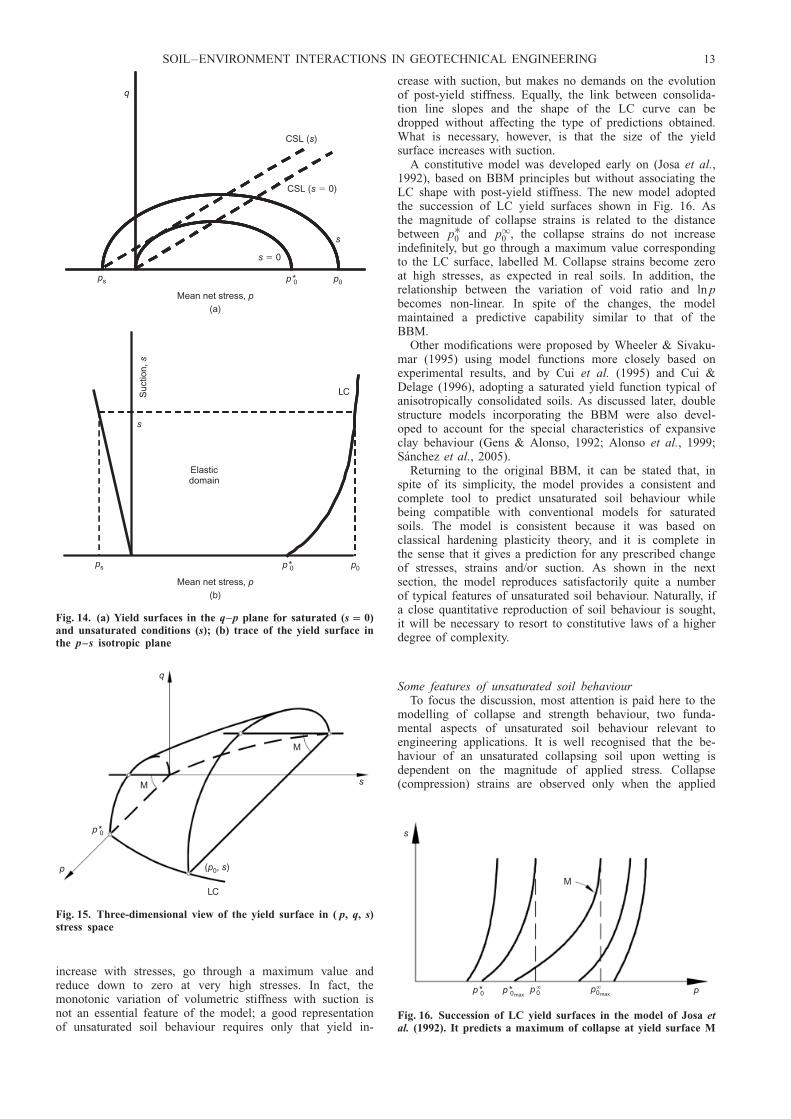
The extension of the model to include deviatoric stressesand strains is illustrated in Fig. 14. In the q–p space (q isthe triaxial deviatoric stress), the curve indicated by the labels ¼ 0 represents the yield surface for saturated conditions.To emphasise the compatibility with saturated models, theellipse of the Modified Cam-clay (MCC) model was chosen,but other yield surface shapes could equally have been used.As suction increases, the ellipse size also increases. On theright-hand side, p0 increases in accordance with the shape ofthe LC yield curve. On the left-hand side, ps increaseslinearly with suction. The implicit assumption here is thatthe friction angle (or the slope of the critical state line) isnot affected by suction, but the apparent cohesion increasesin proportion to suction. The formulation is completed with
a flow rule that may be chosen to be associated or non-associated.
The model is summarised in Fig. 15, which shows athree-dimensional view of the yield surface in p-q-s space. Itis a graphic way to illustrate the generalisation of thesaturated framework via the inclusion of an additional vari-able, suction. The BBM model defined in this way collapsesinto the MCC model when suction becomes zero andsaturated conditions are reached. The original BBM modelalso included a suction increase (SI) yield surface thataccounts for the irreversible strains that occur when suctionincreases beyond maximum past values, but it is not dis-cussed here. In order not to clutter the paper with unneces-sary details, the full model equations have not beenpresented: they can be seen in Alonso et al. (1990). Theconversion of the model from triaxial space to a fully three-dimensional one is straightforward (Gens, 1995).
The choice of net stresses and suction as stress variablesimplies that there may be lack of continuity in the transitionbetween saturated and unsaturated states, a point that isdiscussed more fully later. Another feature of the BBM isthe assumption that there is a link between the shape of theLC yield surface and the post-yield slopes of the virginconsolidation lines at different suctions. Depending on thevalues of parameters pc and r (equations (24) and (25)),computed collapse strains will either continuously increaseor decrease with applied stress (Wheeler et al., 2002).However, it is not possible to predict collapse strains that
s1
s2
s3
Mean net stress,(b)
p
Yield
s 0�
s 0�
Yield curve
LC
Elasticdomain
Mean net stress,(a)
p
Voi
d ra
tio, e
Suc
tion,
s
s3
s2
s1
Fig. 12. (a) Idealised scheme of consolidation lines at differentsuction values: (b) definition of the LC (loading–collapse) yieldcurve in the isotropic plane
Yield curve
LC1
Yield curve
LC2
C
Ls1
Yield curve
Elasticdomain
Yield curveYield curve
( )p0 1S
uctio
n,s
Mean net stress, p( * )p 0 1 ( * )p 0 2
p2
p2 p2
p2
s
1
8
23
5
6
4
9
7
10
11
15
131416
12
Loading
s
p1
p1
p1
p1
p1
p1
p1
p1
2
1
s 0�
1
8
23
5
6
4
9
7
10
11
15
131416
12
18
2
3
5
6
4
9
7
1011
15
13
14
1612
Fig. 13. Displacement of the LC yield curve on loading atconstant suction (path L) and wetting at constant applied stress(path C)
12 GENS
increase with stresses, go through a maximum value andreduce down to zero at very high stresses. In fact, themonotonic variation of volumetric stiffness with suction isnot an essential feature of the model; a good representationof unsaturated soil behaviour requires only that yield in-
crease with suction, but makes no demands on the evolutionof post-yield stiffness. Equally, the link between consolida-tion line slopes and the shape of the LC curve can bedropped without affecting the type of predictions obtained.What is necessary, however, is that the size of the yieldsurface increases with suction.
A constitutive model was developed early on (Josa et al.,1992), based on BBM principles but without associating theLC shape with post-yield stiffness. The new model adoptedthe succession of LC yield surfaces shown in Fig. 16. Asthe magnitude of collapse strains is related to the distancebetween p�0 and p10 , the collapse strains do not increaseindefinitely, but go through a maximum value correspondingto the LC surface, labelled M. Collapse strains become zeroat high stresses, as expected in real soils. In addition, therelationship between the variation of void ratio and ln pbecomes non-linear. In spite of the changes, the modelmaintained a predictive capability similar to that of theBBM.
Other modifications were proposed by Wheeler & Sivaku-mar (1995) using model functions more closely based onexperimental results, and by Cui et al. (1995) and Cui &Delage (1996), adopting a saturated yield function typical ofanisotropically consolidated soils. As discussed later, doublestructure models incorporating the BBM were also devel-oped to account for the special characteristics of expansiveclay behaviour (Gens & Alonso, 1992; Alonso et al., 1999;Sanchez et al., 2005).
Returning to the original BBM, it can be stated that, inspite of its simplicity, the model provides a consistent andcomplete tool to predict unsaturated soil behaviour whilebeing compatible with conventional models for saturatedsoils. The model is consistent because it was based onclassical hardening plasticity theory, and it is complete inthe sense that it gives a prediction for any prescribed changeof stresses, strains and/or suction. As shown in the nextsection, the model reproduces satisfactorily quite a numberof typical features of unsaturated soil behaviour. Naturally, ifa close quantitative reproduction of soil behaviour is sought,it will be necessary to resort to constitutive laws of a higherdegree of complexity.
Some features of unsaturated soil behaviourTo focus the discussion, most attention is paid here to the
modelling of collapse and strength behaviour, two funda-mental aspects of unsaturated soil behaviour relevant toengineering applications. It is well recognised that the be-haviour of an unsaturated collapsing soil upon wetting isdependent on the magnitude of applied stress. Collapse(compression) strains are observed only when the applied
q
CSL ( )s
CSL ( 0)s �
s
Elasticdomain
s
LC
Mean net stress,(a)
p
s 0�
ps p *0 p0
Suc
tion,
s
Mean net stress,(b)
p
ps p *0 p0
Fig. 14. (a) Yield surfaces in the q–p plane for saturated (s 0)and unsaturated conditions (s); (b) trace of the yield surface inthe p–s isotropic plane
q
M
p
p *0
LC
M
s
( , )p s0
Fig. 15. Three-dimensional view of the yield surface in ( p, q, s)stress space
s
M
pp *0 p *0maxp 0
� p0max�
Fig. 16. Succession of LC yield surfaces in the model of Josa etal. (1992). It predicts a maximum of collapse at yield surface M
SOIL–ENVIRONMENT INTERACTIONS IN GEOTECHNICAL ENGINEERING 13

stresses are larger than a certain threshold value: below this,only small volume increases are observed, except, of course,when dealing with expansive clays. Fig. 17 shows a typicalexample of this behaviour, obtained from wetting triaxialtests on K0-consolidated samples of compacted Lower Cro-mer Till (Maswoswe, 1985). In this case, the threshold valueis under 100 kPa. This type of behaviour arises directly fromthe formulation of the BBM model, as illustrated in Fig. 18.If the state of the material is at a point such as C, wettingresults in collapse strains, the magnitude of which can bederived from the movement of the LC yield curve from itsinitial position LCi to its final location LCC. However, if theapplied stress is low (such as that corresponding to point A),the stress path during wetting lies completely in the elasticdomain, and only a small elastic swelling will ensue. It canalso be seen in Fig. 18 that, when the soil collapses onwetting, the final state of the soils lies on, or very close to,the virgin consolidation line of the saturated soil. This isagain a commonly observed behaviour in many unsaturatedsoils, and it is predicted by the model. Since the movementof the LC yield surface is the same whether wetting from Cto N or consolidating under saturated conditions to MN (Fig.18(a)), the plastic volumetric strains will be the same.Elastic strains will also be equal, as they are stress pathindependent. Therefore the total volumetric strains predictedby the model are equal for the two cases, and hence thefinal state of the soil after collapse will be the same as thatobtained in virgin consolidation in saturated conditions.
An additional prediction arises from inspection of Fig. 18.There must be a range of intermediate stress magnitudes(such as that corresponding to point B) for which thevolumetric behaviour upon wetting is more complex. Ac-cording to the model formulation, if a specimen is wettedfrom point B, it should exhibit small swelling strains ini-tially, followed by larger irreversible compression strains asthe LC yield curve is crossed. This behaviour should there-fore be observed in some wetting tests, but only if they areperformed with suction control; otherwise only the netcollapse strains due to flooding of the sample are measured.
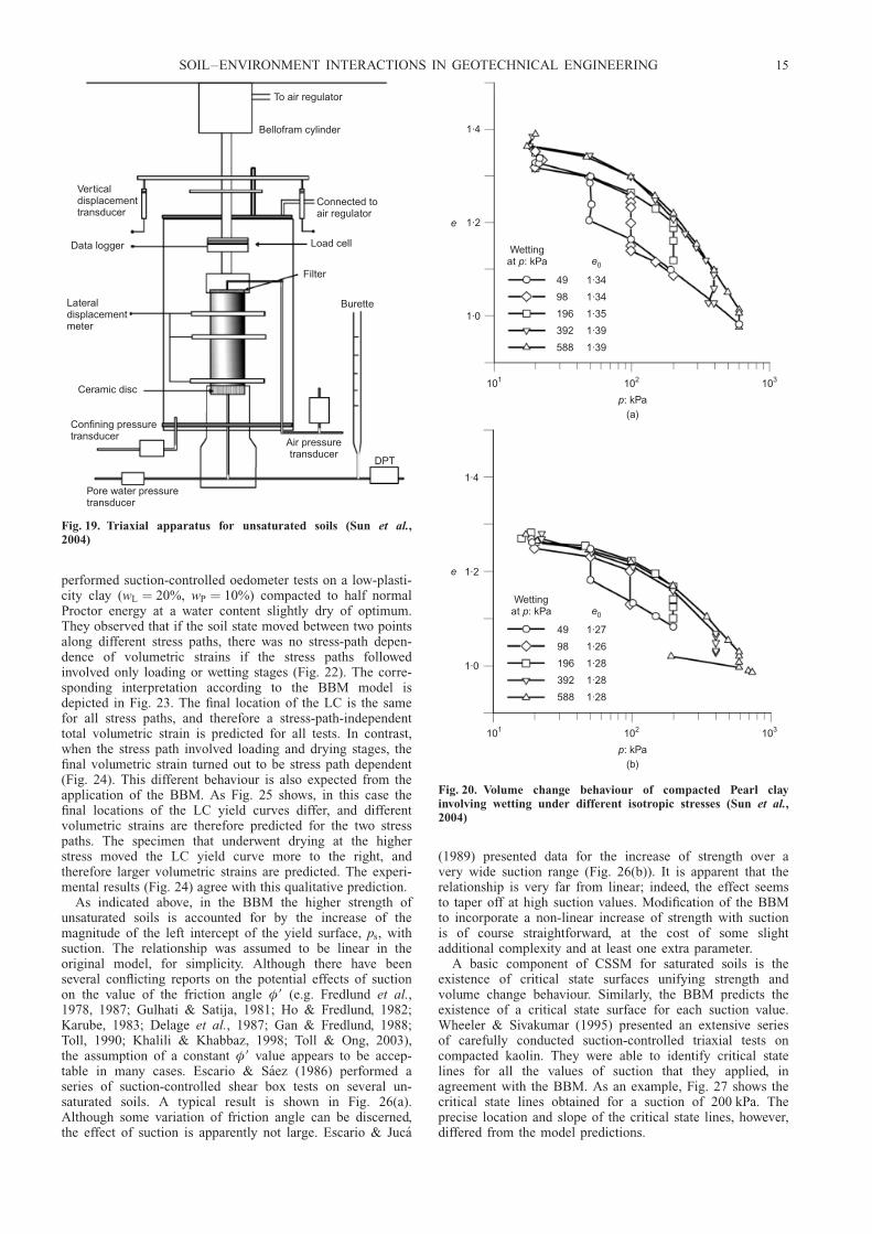
A comprehensive experimental study on the collapse be-haviour of compacted Pearl clay (wL ¼ 49, IP ¼ 27) using asuction-controlled triaxial apparatus has been reported bySun et al. (2004, 2007c). Internal measurements by localtransducers provided the necessary information to trackvolume changes during the test, always a major issue intriaxial testing of unsaturated soils (Fig. 19). The sampleswere formed at various initial densities, and wetting wasperformed under different applied stresses. The behaviour
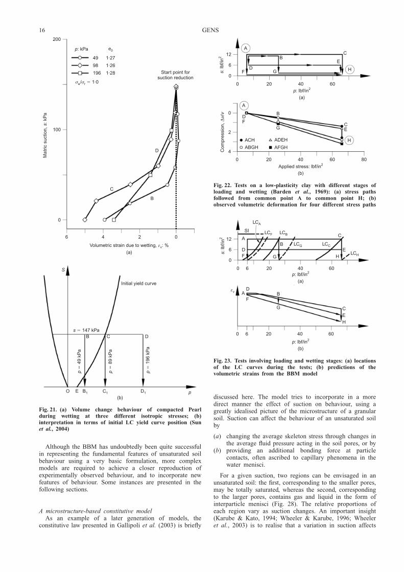
observed has confirmed well-established features of unsatu-rated soil behaviour: collapse strains are larger for the loosersamples and, after wetting, the soil state lies very close tothe saturated consolidation line (Fig. 20). In this case,collapse strains do not increase monotonically with increas-ing wetting stress, but they exhibit a maximum at anintermediate value. Focusing on a particular set of tests, Fig.21(a) shows the evolution of volumetric strains in threewetting tests as suction is reduced. It is interesting to notethat, for the test under the lowest applied stress (49 kPa), thespecimen initially swells on wetting until reaching a suctionvalue where the strain direction reverses and collapse com-pressive strains start accumulating. This is the strain reversalpredicted by the BBM, and corresponds to an initial locationof the LC yield curve as that depicted in Fig. 21(b). In fact,similar observations of strain reversal have been made insuction-controlled tests carried out by, among others, Escario& Saez (1973) and Sivakumar (1993). The fact that such avery specific feature of behaviour arises naturally from theBBM formulation is interpreted as an encouraging sign ofthe basic soundness of the model.
An intriguing observation on path dependence behaviour ofunsaturated soils was reported by Barden et al. (1969). They
0·8
0·6
0·4
0·2
Voi
d ra
tio, e
0·1 1·0 10·0
Vertical stress, : kg/cmσv2
Test no. 8
Swelling Collapse
Fig. 17. Wetting tests on K0-consolidated samples of compactedLower Cromer Till under different applied stresses (Maswoswe,1985)
CB
Suc
tion,
sS
uctio
n,s
(b)
A
Elasticdomain
LCB
NM
Initial yieldcurve LCi LCC
Compression
ABCεvol
Swelling
Elasticswelling
Plasticcompression
( * )p 0 ( * )p 0 B ( * )p 0 C
Mean net stress,(a)
p
Fig. 18. (a) Stress paths for wetting tests performed under threedifferent applied stresses; (b) predicted volumetric strains forwetting tests performed under three different applied stresses
14 GENS
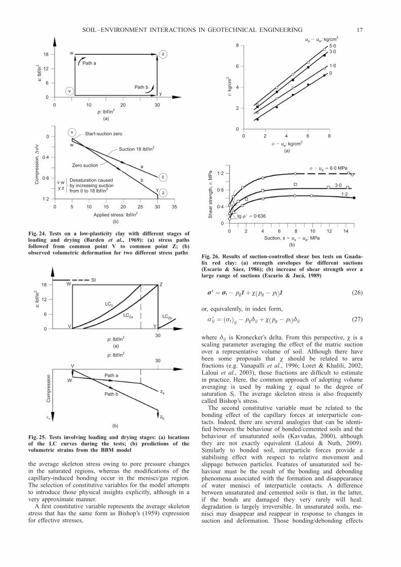
performed suction-controlled oedometer tests on a low-plasti-city clay (wL ¼ 20%, wP ¼ 10%) compacted to half normalProctor energy at a water content slightly dry of optimum.They observed that if the soil state moved between two pointsalong different stress paths, there was no stress-path depen-dence of volumetric strains if the stress paths followedinvolved only loading or wetting stages (Fig. 22). The corre-sponding interpretation according to the BBM model isdepicted in Fig. 23. The final location of the LC is the samefor all stress paths, and therefore a stress-path-independenttotal volumetric strain is predicted for all tests. In contrast,when the stress path involved loading and drying stages, thefinal volumetric strain turned out to be stress path dependent(Fig. 24). This different behaviour is also expected from theapplication of the BBM. As Fig. 25 shows, in this case thefinal locations of the LC yield curves differ, and differentvolumetric strains are therefore predicted for the two stresspaths. The specimen that underwent drying at the higherstress moved the LC yield curve more to the right, andtherefore larger volumetric strains are predicted. The experi-mental results (Fig. 24) agree with this qualitative prediction.
As indicated above, in the BBM the higher strength ofunsaturated soils is accounted for by the increase of themagnitude of the left intercept of the yield surface, ps, withsuction. The relationship was assumed to be linear in theoriginal model, for simplicity. Although there have beenseveral conflicting reports on the potential effects of suctionon the value of the friction angle �9 (e.g. Fredlund et al.,1978, 1987; Gulhati & Satija, 1981; Ho & Fredlund, 1982;Karube, 1983; Delage et al., 1987; Gan & Fredlund, 1988;Toll, 1990; Khalili & Khabbaz, 1998; Toll & Ong, 2003),the assumption of a constant �9 value appears to be accep-table in many cases. Escario & Saez (1986) performed aseries of suction-controlled shear box tests on several un-saturated soils. A typical result is shown in Fig. 26(a).Although some variation of friction angle can be discerned,the effect of suction is apparently not large. Escario & Juca
(1989) presented data for the increase of strength over avery wide suction range (Fig. 26(b)). It is apparent that therelationship is very far from linear; indeed, the effect seemsto taper off at high suction values. Modification of the BBMto incorporate a non-linear increase of strength with suctionis of course straightforward, at the cost of some slightadditional complexity and at least one extra parameter.
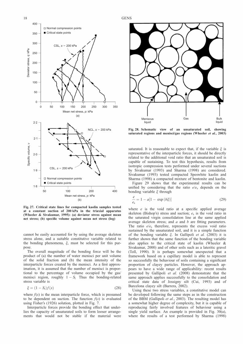
A basic component of CSSM for saturated soils is theexistence of critical state surfaces unifying strength andvolume change behaviour. Similarly, the BBM predicts theexistence of a critical state surface for each suction value.Wheeler & Sivakumar (1995) presented an extensive seriesof carefully conducted suction-controlled triaxial tests oncompacted kaolin. They were able to identify critical statelines for all the values of suction that they applied, inagreement with the BBM. As an example, Fig. 27 shows thecritical state lines obtained for a suction of 200 kPa. Theprecise location and slope of the critical state lines, however,differed from the model predictions.
To air regulator
Bellofram cylinder
Connected toair regulator
Verticaldisplacementtransducer
Data logger
Lateraldisplacementmeter
Ceramic disc
Confining pressuretransducer
Pore water pressuretransducer
Load cell
Filter
Burette
DPT
Air pressuretransducer
Fig. 19. Triaxial apparatus for unsaturated soils (Sun et al.,2004)
1·4
1·2e
1·0
101 102 103
p: kPa(a)
Wettingat : kPap e0
49
98
196
392
588
1·34
1·34
1·35
1·39
1·39
1·4
1·2e
1·0
101 102 103
p: kPa(b)
Wettingat : kPap e0
49
98
196
392
588
1·27
1·26
1·28
1·28
1·28
Fig. 20. Volume change behaviour of compacted Pearl clayinvolving wetting under different isotropic stresses (Sun et al.,2004)
SOIL–ENVIRONMENT INTERACTIONS IN GEOTECHNICAL ENGINEERING 15
Although the BBM has undoubtedly been quite successfulin representing the fundamental features of unsaturated soilbehaviour using a very basic formulation, more complexmodels are required to achieve a closer reproduction ofexperimentally observed behaviour, and to incorporate newfeatures of behaviour. Some instances are presented in thefollowing sections.
A microstructure-based constitutive modelAs an example of a later generation of models, the
constitutive law presented in Gallipoli et al. (2003) is briefly
discussed here. The model tries to incorporate in a moredirect manner the effect of suction on behaviour, using agreatly idealised picture of the microstructure of a granularsoil. Suction can affect the behaviour of an unsaturated soilby
(a) changing the average skeleton stress through changes inthe average fluid pressure acting in the soil pores, or by
(b) providing an additional bonding force at particlecontacts, often ascribed to capillary phenomena in thewater menisci.
For a given suction, two regions can be envisaged in anunsaturated soil: the first, corresponding to the smaller pores,may be totally saturated, whereas the second, correspondingto the larger pores, contains gas and liquid in the form ofinterparticle menisci (Fig. 28). The relative proportions ofeach region vary as suction changes. An important insight(Karube & Kato, 1994; Wheeler & Karube, 1996; Wheeleret al., 2003) is to realise that a variation in suction affects
6 4 2 0
Volumetric strain due to wetting, : %
(a)
εv
200
100
0
Ma
tric
suc
tion,
: kP
as
D
C
B
Start point forsuction reduction
p: kPa e0
σ σa r/ 1·0�
49
98
196
1·27
1·26
1·28
S
Initial yield curve
O E B1 C1 D1 p
s 147 kPa�
p49
kP
a�
p89
kP
a�
p19
6 kP
a�
B C D
(b)
Fig. 21. (a) Volume change behaviour of compacted Pearlduring wetting at three different isotropic stresses; (b)interpretation in terms of initial LC yield curve position (Sunet al., 2004)
12
6
0
s: lb
f/in2
A
FD
G
B
0 20 40 60
H
E
C
p: lbf/in(a)
2
A
BDF
GCE
HACH
ABGH
ADEH
AFGH
0 20 40 60 80
Applied stress: lbf/in(b)
2
4
2
0
Com
pres
sion
,/
∆v
v
Fig. 22. Tests on a low-plasticity clay with different stages ofloading and wetting (Barden et al., 1969): (a) stress pathsfollowed from common point A to common point H; (b)observed volumetric deformation for four different stress paths
12
6
0
s: lb
f/in2
SI
LCA
LCF LCB
B
G
A
DF
LCG LCC
C
HE
LCH
0 6 20 40 60p: lbf/in
(a)
2
B
G
AD
F
C
HE
0 6 20 40 60
p: lbf/in(b)
2
εv
Fig. 23. Tests involving loading and wetting stages: (a) locationsof the LC curves during the tests; (b) predictions of thevolumetric strains from the BBM model
16 GENS
the average skeleton stress owing to pore pressure changesin the saturated regions, whereas the modifications of thecapillary-induced bonding occur in the menisci/gas region.The selection of constitutive variables for the model attemptsto introduce those physical insights explicitly, although in avery approximate manner.
A first constitutive variable represents the average skeletonstress that has the same form as Bishop’s (1959) expressionfor effective stresses,
�9 ¼ �t � pgI þ � pg � plð ÞI (26)
or, equivalently, in index form,
� 9ij ¼ � tð Þij� pgij þ � pg � plð Þij (27)
where ij is Kronecker’s delta. From this perspective, � is ascaling parameter averaging the effect of the matric suctionover a representative volume of soil. Although there havebeen some proposals that � should be related to areafractions (e.g. Vanapalli et al., 1996; Loret & Khalili, 2002;Laloui et al., 2003), those fractions are difficult to estimatein practice. Here, the common approach of adopting volumeaveraging is used by making � equal to the degree ofsaturation Sl. The average skeleton stress is also frequentlycalled Bishop’s stress.
The second constitutive variable must be related to thebonding effect of the capillary forces at interparticle con-tacts. Indeed, there are several analogies that can be identi-fied between the behaviour of bonded/cemented soils and thebehaviour of unsaturated soils (Kavvadas, 2000), althoughthey are not exactly equivalent (Laloui & Nuth, 2009).Similarly to bonded soil, interparticle forces provide astabilising effect with respect to relative movement andslippage between particles. Features of unsaturated soil be-haviour must be the result of the bonding and debondingphenomena associated with the formation and disappearanceof water menisci of interparticle contacts. A differencebetween unsaturated and cemented soils is that, in the latter,if the bonds are damaged they very rarely will heal:degradation is largely irreversible. In unsaturated soils, me-nisci may disappear and reappear in response to changes insuction and deformation. Those bonding/debonding effects
18
12
6
0
s: lb
f/in2
w
v
z
Path a
Path by
0 10 20 30
p: lbf/in(a)
2
0
0·4
0·8
1·2
Com
pres
sion
,/
∆v
v
v
w
Zero suction
Suction 18 lbf/in2
Start-suction zero
a
bz
yz
0 5 10 15 20 25 30 35
Applied stress: lbf/in(b)
2
v wy z
���
Desaturation causedby increasing suctionfrom 0 to 18 lbf/in2
Fig. 24. Tests on a low-plasticity clay with different stages ofloading and drying (Barden et al., 1969): (a) stress pathsfollowed from common point V to common point Z; (b)observed volumetric deformation for two different stress paths
30p: lbf/in2
Path a
Path bza
zb
V
W
εv
Com
pres
sion
18
12
6
0
s: lb
f/in2
WSI
V
LCV
LCZa LCZb
Z
Y
30p: lbf/in
(a)
2
(b)
Fig. 25. Tests involving loading and drying stages: (a) locationsof the LC curves during the tests; (b) predictions of thevolumetric strains from the BBM model
8
6
4
2
0
τ: k
g/cm
2
0 2 4 6 8
σ : kg/cm
(a)
� ua2
u ua w2: kg/cm�
5·03·0
1·0
0
1·2
0·8
0·4
0
She
ar s
tren
gth,
: MP
aτ
0 2 4 6 8 10 12 14
Suction, : MPa(b)
s u u� �a w
tg 0·636φ� �
3·0
1·2
σ 6·0 MPa� �ua
Fig. 26. Results of suction-controlled shear box tests on Guada-lix red clay: (a) strength envelopes for different suctions(Escario & Saez, 1986); (b) increase of shear strength over alarge range of suctions (Escario & Juca, 1989)
SOIL–ENVIRONMENT INTERACTIONS IN GEOTECHNICAL ENGINEERING 17
cannot be easily accounted for by using the average skeletonstress alone, and a suitable constitutive variable related tothe bonding phenomena, , must be selected for this pur-pose.
The overall magnitude of the bonding force will be theproduct of (a) the number of water menisci per unit volumeof the solid fraction and (b) the mean intensity of theinterparticle forces created by the menisci. As a first approx-imation, it is assumed that the number of menisci is propor-tional to the percentage of volume occupied by the gas/menisci region, roughly 1 � Sl: Thus the bonding-relatedstress variable is
¼ 1 � Slð Þ f sð Þ (28)
where f (s) is the mean interparticle force, which is presumedto be dependent on suction. The function f (s) is evaluatedusing Fisher’s (1926) solution, plotted in Fig. 7.
Interparticle forces provide the bonding effect that under-lies the capacity of unsaturated soils to form looser arrange-ments that would not be stable if the material were
saturated. It is reasonable to expect that, if the variable isrepresentative of the interparticle forces, it should be directlyrelated to the additional void ratio that an unsaturated soil iscapable of sustaining. To test this hypothesis, results fromisotropic compression tests performed under several suctionsby Sivakumar (1993) and Sharma (1998) are considered.Sivakumar (1993) tested compacted Speswhite kaolin andSharma (1998) a compacted mixture of bentonite and kaolin.
Figure 29 shows that the experimental results can beunified by considering that the ratio e/es depends on thebonding variable through
e
es
¼ 1 � a 1 � exp bð Þ½ � (29)
where e is the void ratio at a specific applied averageskeleton (Bishop’s) stress and suction; es is the void ratio inthe saturated virgin consolidation line at the same appliedaverage skeleton stress; and a and b are fitting parameters.The ratio e/es therefore, represents the excess void ratiosustained by the unsaturated soil, and it is a simple functionof the bonding variable . In Gallipoli et al. (2003) it isfurther shown that the same function of the bonding variablealso applies to the critical state of kaolin (Wheeler &Sivakumar, 2000) and of other soils such as a lateritic gravel(Toll, 1990). It is perhaps somewhat unexpected that aframework based on a capillary model is able to representso successfully the behaviour of soils containing a significantproportion of clayey particles. However, the approach ap-pears to have a wide range of applicability: recent resultspresented by Gallipoli et al. (2008) demonstrate that thesame approach applies successfully to the consolidation andcritical state data of Jossigny silt (Cui, 1993) and ofBarcelona clayey silt (Barrera, 2002).
Using these two stress variables, a constitutive model canbe developed following the same steps as in the constructionof the BBM (Gallipoli et al., 2003). The resulting model hasa somewhat higher degree of complexity, but it is capable ofreproducing fairly involved features of behaviour using asingle yield surface. An example is provided in Fig. 30(a),where the results of a test performed by Sharma (1998)
400
350
300
250
200
150
100
50
0
Dev
iato
r st
ress
, :
kPa
qNormal compression points
Critical state points
CSL, 200 kPas �
0 50 100 150 200 250 300 350
Mean net stress, : kPa(a)
p
2·2
2·1
2·0
1·9
1·8
50 100 200 400
Spe
cific
vol
ume,
v
Normal compression points
Critical state points
CSL, 200 kPas �
Mean net stress, : kPa(b)
p
NCL, 200 kPas �
Fig. 27. Critical state lines for compacted kaolin samples testedat a constant suction of 200 kPa in the triaxial apparatus(Wheeler & Sivakumar, 1995): (a) deviator stress against meannet stress; (b) specific volume against mean net stress (log)
Meniscusliquid
Gas Bulkliquid
Fig. 28. Schematic view of an unsaturated soil, showingsaturated regions and menisci/gas regions (Wheeler et al., 2003)
18 GENS

involving two cycles of wetting and drying are plottedtogether with the computed results using the model. Goodagreement can be noted, in spite of the rather intricatebehaviour observed. Fig. 30(b) shows the stress path fol-lowed by the test (in the space defined by the averageskeleton stress and the bonding variable ) and the succes-sive locations of the LC yield curve of the model. Naturally,to be able to draw the stress paths, it is necessary to knowthe value of the degree of saturation throughout the test. Itis quite apparent that, in the space of the new variables, thestress paths followed by simple drying/wetting tests becomequite involved and non-intuitive. It is interesting to note thatthe additional compression that is observed in both dryingstages would not be obtained by the BBM model unless anadditional yield surface with a complex hardening behaviourwas specified. In the new model, the behaviour is readilyreproduced employing a single LC yield surface and noadditional assumptions.
Coupling hydraulic and mechanical behaviourThe hydraulic constitutive behaviour linking suction and
degree of saturation (or water content) plays an importantrole in the case of unsaturated soils: retention curve andmechanical behaviour are in fact coupled. Changes in degreeof saturation per se produce mechanical effects whereas, inturn, soil deformation modifies the degree of saturation. Inthe BBM and other models, the hydraulic behaviour wassimply represented by an ad hoc state surface. If the modelis defined in terms of net stresses, the hydraulic componentis separate from the mechanical one, so inaccuracies in thehydraulic formulation do not affect directly mechanical pre-dictions, except when soil parameters are made to dependon water content (Chiu & Ng, 2003; Thu et al., 2007). Onthe other hand, in models where the degree of saturation orother hydraulic parameters enter the definition of the consti-tutive variables, the hydraulic-mechanical constitutive coup-ling must be carefully considered.
1·4
1·3
1·2
1·1
1·0
s 100 kPa�
s 200 kPa�
s 300 kPa�
1·4
1·3
1·2
1·1
1·0
Exp. ( 100 kPa)s �
Exp. (s 200 kPa)�
Exp. (s 300 kPa)�
Model equation
0 0·2 0·4 0·6
�(d)
e e/
s
1·4
1·3
1·2
1·1
0·9
1·0
0·8
e
40 70 100 300 500
Average skeleton stress: kPa(a)
s 0 kPa (saturated)�
Exp. ( 100 kPa)s �
Exp. (s 200 kPa)�
Exp. (s 300 kPa)�
1·4
1·3
1·2
1·1
0·9
1·0
0·8
e
40 70 100 300 500
Average skeleton stress: kPa(b)
s 0 kPa (saturated)�
s 100 kPa�
s 200 kPa�
s 300 kPa�
Model equation
0 0·2 0·4 0·6
�(c)
e e/
s
Fig. 29. (a) Normal isotropic compression lines at constant suction in terms of average skeleton stress (Sharma, 1998);(b) excess void ratio over the stable saturated void ratio (e/es) as a function of the bonding variable � (data by Sharma,1998); (c) normal isotropic compression lines at constant suction in terms of average skeleton stress (Sivakumar, 1993);(d) excess void ratio over the stable saturated void ratio (e/es) as a function of the bonding variable � (data by Sivakumar,1993) (Gallipoli et al., 2003)
SOIL–ENVIRONMENT INTERACTIONS IN GEOTECHNICAL ENGINEERING 19
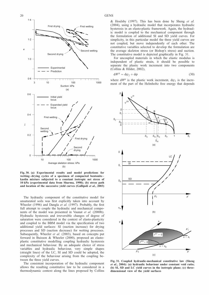
The hydraulic component of the constitutive model forunsaturated soils was first explicitly taken into account byWheeler (1996) and Dangla et al. (1997). Probably, the firstfull attempt to couple the hydraulic and mechanical compo-nents of the model was presented in Vaunat et al. (2000b).Hydraulic hysteresis and irreversible changes of degree ofsaturation were considered in the context of elasto-plasticityand coupled to the BBM model via the specification of twoadditional yield surfaces: SI (suction increase) for dryingprocesses and SD (suction decrease) for wetting processes.Subsequently, Wheeler et al. (2003), based on concepts putforward in Buisson & Wheeler (2000), proposed an elasto-plastic constitutive modelling coupling hydraulic hysteresisand mechanical behaviour. By an adequate choice of stressvariables and hydraulic behaviour, very simple shapes(straight lines) of the LC, SI and SD could be adopted, thecomplexity of the behaviour arising from the coupling be-tween the three yield curves.
The consistent incorporation of the hydraulic componentallows the resulting constitutive law to be considered in athermodynamic context along the lines proposed by Collins
& Houlsby (1997). This has been done by Sheng et al.(2004), using a hydraulic model that incorporates hydraulichysteresis in an elasto-plastic framework. Again, the hydraul-ic model is coupled to the mechanical component throughthe formulation of additional SI and SD yield curves. Forsimplicity, in this particular model the three yield curves arenot coupled, but move independently of each other. Theconstitutive variables selected to develop the formulation arethe average skeleton stress (or Bishop’s stress) and suction.The constitutive model is depicted graphically in Fig. 31.
For uncoupled materials in which the elastic modulus isindependent of plastic strain, it should be possible toseparate the plastic work increment into two components(Collins & Hilder, 2002),
dW p ¼ dł2 þ d� (30)
where dWp is the plastic work increment, dł2 is the incre-ment of the part of the Helmholtz free energy that depends
Initial yieldlocus
1·4
1·2
1·0
0·8
e
First drying First wetting
Second wettingSecond drying
Experimental
Prediction
3 10 100 1000Suction: kPa
(a)
0·6
0·4
0·2
0
First drying
First wetting
Secondwetting
Seconddrying
Expanded yieldlocus
10 100 1000Average skeleton stress: kPa
(b)
�
Fig. 30. (a) Experimental results and model predictions forwetting–drying cycles of a specimen of compacted bentonite–kaolin mixture subjected to a constant isotropic net stress of10 kPa (experimental data from Sharma, 1998); (b) stress pathand location of the successive yield curves (Gallipoli et al., 2003)
S
SSI
S0SDS
C
B
AG
FE
D
H
ψSI
ψSD
Src Srb Sre
Sr0
Srf 1 Sr
(a)
S
SI
SD
SD
SI
LC
uw
p �0 p�
(b)
q s
p �c
s s� I
p�p �0
s s� D
f LC 0�
f SD� 0
(c)
SI
SD
LC
p�p�0
Fig. 31. Coupled hydraulic-mechanical constitutive law (Shenget al., 2004): (a) hydraulic behaviour under constant void ratio;(b) SI, SD and LC yield curves in the isotropic plane; (c) three-dimensional view of the yield surfaces
20 GENS

on plastic strains only, and d� is the dissipation increment.The basic thermodynamical requirements for the constitutivemodel are that (a) the dissipation is strictly positive for anynon-zero plastic strain, and (b) the free energy dł2 yieldszero when integrated over a closed loop of plastic strain.
In triaxial stress variables, the plastic work increment canbe written as
dW p ¼ p9d�pv þ qd�p
ª þ nsIdSpl þ nsDdS
pl (31)
where p9 is the mean Bishop’s stress, q is the triaxialdeviatoric stress, �v is the volumetric strain, �ª is the triaxialdeviatoric strain, n is the porosity, s is suction and Sl is thedegree of saturation. The superscript p denotes plastic. Thethird and fourth terms will occur when the SI or SD yieldcurves are engaged respectively. To obtain a suitable formu-lation from the thermodynamical point of view, it is neces-sary to postulate that the flow rule of the SI and SD yieldsurfaces is associated, and that therefore plastic volumetricand plastic deviatoric strains are caused only by the move-ment of the LC yield curve. In this case it is possible toidentify the two thermodynamic functions with the correctset of properties,
dł2 ¼ 1
2p9d�p
v þ nsIdSpr þ nsDdSp
r (32)
d� ¼ 1
2p9
d�pvð Þ2 þ M2=�
� �d�p
ª
� �2ffiffiffiffiffiffiffiffiffiffiffiffiffiffiffiffiffiffiffiffiffiffiffiffiffiffiffiffiffiffiffiffiffiffiffiffiffiffiffiffiffiffiffiffiffiffiffid�p
vð Þ2 þ M2=�� �
d�pª
� �2q > 0 (33)
where M is the slope of the critical state line in q–p9 space,and � is a parameter defining the flow rule of the main yieldsurface (� ¼ 1, for associated plasticity). The dissipationfunction (equation (33)) is obviously strictly positive when-ever the plastic strains are non-zero, as required. Equations(32) and (33) indicate that the plastic yielding at thesuction-increase and suction-decrease yield surfaces does notcontribute to the plastic dissipation, but only to the plasticwork. This means that all plastic work associated with aplastic increment of degree of saturation is stored, and canbe recovered during a reversed plastic increment of satura-tion. This plastic work is very much the same as the‘locked-in elastic energy’ due to the shift or back stressdescribed in Collins & Hilder (2002).
In this way, it has been demonstrated that it is possible toconstruct a hydromechanical constitutive law, acceptingsome restrictive assumptions, consistent with a thermo-dynamical framework. Tamagnini & Pastor (2005) haveperformed a similar exercise for a generalised plasticitymodel, showing that this thermodynamic consistency is notlimited to a single class of models.
Cemented unsaturated soilsMost of the experimentally observed behaviour mentioned
above has been obtained from laboratory tests on compactedsoils; far less information is available for natural unsaturatedsoils. The unavoidable variability of natural soils makes themless suited to fundamental investigation, as it is quite difficultto achieve adequate repeatability of test results. An additionalcomplexity arises from the fact that soils in arid regions arelikely to be cemented to some degree. Wind-blown depositssuch as loess exhibit open structures and a certain amount ofrather soft bonding: this is also the case for other naturalmaterials such as volcanic aggregates, as well as gypseous,salty and carbonated silts and sands. Residual soils are alsofrequently bonded as a relict of the rock structure still presentto some degree within the weathered soil.
Building on the contribution by Leroueil & Vaughan
(1990), Gens & Nova (1993) proposed a set of conceptualbases for developing constitutive models for saturatedbonded or cemented soils. It is based on the introduction ofa bonding parameter that allows a bonded soil to sustain ahigher void ratio than would be possible for the same soilwithout any bonding (Fig. 32(a)). The outcome is a series ofclassical yield surfaces, the sizes of which increase withincreasing amount of bonding (Fig. 32(b)). The parallelswith the effect of suction in unsaturated soils are evident,suggesting that a model for cemented unsaturated soils couldbe obtained by simply adding the effects of suction to thoseof bonding. However, the situation may be more complex,because there may be some interaction between the effectsof suction and bonding, as surmised in Alonso & Gens(1994). Lack of experimental evidence at the time preventedthis issue from being settled.
Subsequently, Leroueil & Barbosa (2000) carried out asystematic, well-controlled series of constant strain rate(CSR) oedometer tests on artificially cemented and uncemen-ted soils under controlled suction (Figs 33(a) and 33(b)). Thesamples were made by statically compacting a Braziliansaprolite from gneiss at a water content of 14% and void ratioof 1.4. In one of the test series, 2% cement was added to the
Voi
d ra
tio, e
p�
∆e
b 0� b1 b2 b3
b b b1 2 3� �
(a)
q
M
pt
A B C
p�pc0pc
(b)
Fig. 32. (a) Consolidation lines for soils with increasing degreesof bonding; (b) successive yield surfaces for soils with increasingdegrees of bonding (surface A corresponds to unbondedmaterial) (Gens & Nova, 1993)
SOIL–ENVIRONMENT INTERACTIONS IN GEOTECHNICAL ENGINEERING 21
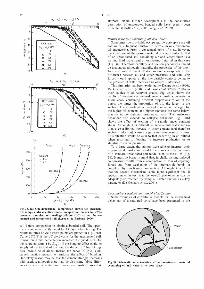
soil before compaction to obtain a bonded soil. The speci-mens were subsequently cured for 45 days before testing. Theresults in terms of yield stress points are plotted in Fig. 33(c).Curve LC(0%) is the LC yield curve for the uncemented soil.It was found that cementation increased the yield stress forthe saturated sample by ˜�y,st. If the bonding effect could besimply added to that of suction, the dashed LC line of Fig.33(c) would be obtained. Instead the curve LC(2%) is ob-served: suction appears to reinforce the effect of bonding.One likely reason may be that the cement strength increaseswith suction, although there may be also some fabric differ-ences between cemented and uncemented soils (Leroueil &
Barbosa, 2000). Further developments in the constitutivedescription of unsaturated bonded soils have recently beenpresented (Garitte et al., 2006; Yang et al., 2009).
Porous materials containing oil and waterSometimes the two fluids occupying the pore space are oil
and water, a frequent situation in petroleum or environmen-tal engineering. From a conceptual point of view, however,the condition of the porous material is very similar to thatof an unsaturated soil containing air and water: there is awetting fluid, water, and a non-wetting fluid, oil in this case(Fig. 34). Therefore capillary and suction phenomena shouldbe analogous, although, naturally, the properties of the inter-face are quite different. Matric suction corresponds to thedifference between oil and water pressures, and stabilisingforces should appear at the interparticle contacts owing tothe presence of water menisci and water/oil interfaces.
This similarity has been exploited by Delage et al. (1996),De Gennaro et al. (2004) and Priol et al. (2005, 2006) intheir studies of oil-reservoir chalks. Fig. 35(a) shows theresults of constant suction oedometer consolidation tests onLixhe chalk containing different proportions of oil in thepores: the larger the proportion of oil, the larger is thesuction. The consolidation lines plot more to the right forthe higher oil contents and higher suctions, the same behav-iour as in conventional unsaturated soils. The analogousbehaviour also extends to collapse behaviour. Fig. 35(b)shows the effect of wetting of a sample under constantstress. Although it is difficult to achieve full water satura-tion, even a limited increase in water content (and thereforesuction reduction) causes significant compressive strains.This situation would be akin to that occurring in an oilfieldwhen resorting to flooding to increase production or tostabilise reservoir pressures.
To a large extent the authors were able to interpret theirexperimental results and model them successfully in termsof a standard unsaturated soil model such as the BBM (Fig.36). It must be borne in mind that, in chalk, wetting-inducedcompression results from a combination of loss of capillaryforces and from weakening of the interparticle bonds—acomplex physico-chemical interaction. Although it is likelythat the second mechanism is the more significant one, itappears, nevertheless, that the overall phenomenon can beadequately represented by using oil–water suction as a keyparameter (De Gennaro et al., 2004).
Constitutive variables and model classificationSome examples of constitutive models for the mechanical
behaviour of unsaturated soils have been presented in the
0
5
10
15
20
25
30
35
Ver
tical
str
ain:
%10 102 103
( ) or ( ): kPaσ σa a a w� �u u
CRS tests
( ): kPau ua w�
0
50
100
200
300
500
(a)
0
5
10
15
20
25
30
Ver
tical
str
ain:
%
10 102 103
( ) or ( ): kPaσ σa a a w� �u u
CRS tests
( ): kPau ua w�
03050
100300500
(b)
σy,e
500
0
100
200
300
400
Suc
tion:
kP
a
0 40 80 120 160 200
p u( ): kPa
(c)
� �σa a
Cement0%2%
LC (0%)
LC (2%)
∆σy,suc ∆σy,st ∆σy,st suc�
Fig. 33. (a) One-dimensional compression curves for uncemen-ted samples; (b) one-dimensional compression curves for (2%)cemented samples; (c) loading–collapse (LC) curves for ce-mented and uncemented soil (Leroueil & Barbosa, 2000)
Oil
Water
Soil skeleton
Fig. 34. Schematic representation of an unsaturated materialcontaining oil and water in its pore space
22 GENS

previous sections to illustrate the range of possibilities inthis respect. Numerous constitutive models for unsaturatedsoils have been developed in recent years: many of themadopt a classical elasto-plastic framework, but other types offormulation have also been used, such as generalised plasti-city (Bolzon et al., 1996; Sanchez et al., 2005; Tamagniniand Pastor, 2005) or hypoplasticity (Masin & Khalili, 2008).To conclude this section on mechanical constitutive modelsfor unsaturated soils, a series of general remarks on theseconstitutive developments are presented. For more detailedcomments, several review articles on the subject are avail-able (Gens, 1996; Wheeler & Karube, 1996; Jommi, 2000;Wheeler, 2005; Gens et al., 2006, 2008b; Sheng & Fredlund,2008; Sheng et al., 2008b).
A variety of constitutive variables have been used todefine the different models, a matter that has sparked acertain amount of controversy. In principle, any relevantvariable can be selected as a constitutive variable but, forengineering purposes, constitutive laws are usually (but notalways) defined in stress space: that is, using scalar, vectoror tensor variables that have units of stresses. However, itwould be possible to adopt other types of variable (e.g.degree of saturation, water content) if they had a greaterdescriptive or predictive power.
There is general agreement that at least two constitutivevariables are generally required to represent adequately thefull range of unsaturated soil behaviour, that is, includingstrength and deformation. As stated by Jommi (2000): ‘Infact, no single stress variable has ever been found which,substituted for effective stress, allows a description of allthe aspects of the mechanical behaviour of a given soil inthe unsaturated range.’ It is convenient to refer to them asthe first and second constitutive variables (FCV and SCV).They are intentionally not called constitutive stress variables,to leave open the possibility that variable types other thanstresses might be adopted. Usually, the FCV tries to accountfor the overall stress state of the soil, whereas the SCVtends to address mainly the effects of suction changes. Thus,if the constitutive variables chosen are net stresses andsuction (as in the BBM), the FCV (net stress) responds toloading changes whereas the SCV (suction) deals withenvironmental actions related to suction variations. The samecomment can be made if, as in the model of Gallipoli et al.(2003) described above, average skeleton stress and a bond-ing parameter are used. In any case, in the majority ofconstitutive models developed, those two constitutive vari-ables normally adopt the general form
FCV:
� tð Þij� pgij þ �1 s, Slð Þij (34a)
SCV:
�2 s, Slð Þ (34b)
The FCV is expressed as a modified stress tensor; incontrast, for the SCV, aiming to represent the additionaleffects of suction, a scalar is usually adopted. However, oneof the main effects of suction is the generation of stabilisinginterparticle forces. It would be reasonable to expect, aspointed out by Li (2003) and Scholtes et al. (2009), that theSCV should incorporate some kind of fabric measure of thesoil; the variable would then no longer be a scalar, morelikely a tensor. Indeed, if suction effects have a tensorialform, it is questionable that an averaged pressure in the fluidphase is an adequate representation of the role of suction,even when defining the FCV (Scholtes et al., 2009). In anycase, the use of a tensorial form for the effects of suction isdifficult to accomplish, owing to the complexity of determin-ing the soil fabric and its variation as soil deforms. Accord-
0·7
0·6
0·5
Voi
d ra
tio, e
1·0 10·0Mean net stress, : MPa
(a)p
T1 (0 kPa)
T5 (200 kPa)T7 (1000 kPa)
T2 (1500 kPa)
0·72
0·68
0·64
0·60
0·56
Voi
d ra
tio, e
0·01 0·10 1 10 100
Vertical stress, : MPa
(b)
σv
A
B
Oil saturated chalk
Water injection( 10 MPa)σv �
S 0·1 MPa�
Fig. 35. Suction-controlled oedometer tests on oil-containingLixhe chalk: (a) consolidation tests with different suctions(modified from Priol et al., 2005); (b) wetting test at constantstress (De Gennaro et al., 2004)
3000
2000
1000
0
Suc
tion:
kP
a
0 4 8 12
Yield mean net stress: MPa
Oil saturated
LC curve
Water saturated
Yielding
Fig. 36. LC yield curve for oil-containing Lixhe chalk (DeGennaro, personal communication 2007)
SOIL–ENVIRONMENT INTERACTIONS IN GEOTECHNICAL ENGINEERING 23
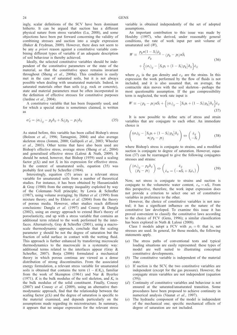
ingly, scalar definitions of the SCV have been dominanthitherto. It can be argued that suction has a differentphysical nature from stress variables (Lu, 2008), and someobjections have been put forward concerning the validity ofcombining stresses and suction into a single expression(Baker & Frydman, 2009). However, there does not seem tobe any a priori reason against a constitutive variable com-bining different types of variable if an adequate descriptionof soil behaviour is thereby achieved.
Ideally, the selected constitutive variables should be inde-pendent of the constitutive parameters or the state of thematerial, so that the constitutive space remains invariantthroughout (Sheng et al., 2008a). This condition is easilymet in the case of saturated soils, but it is not alwayspossible when dealing with unsaturated materials. Indeed, insaturated materials other than soils (e.g. rock or concrete),state and material parameters must be often incorporated inthe definition of effective stresses for constitutive purposes(Jardine et al., 2004).
A constitutive variable that has been frequently used, andfor which a special status is sometimes claimed, is writtenas
� 9ij ¼ � tð Þij� pgij þ Sl pg � plð Þij (35)
As stated before, this variable has been called Bishop’s stress(Bolzon et al., 1996; Tamagnini, 2004) and also averageskeleton stress (Jommi, 2000; Gallipoli et al., 2003; Wheeleret al., 2003). Other terms that have also been used areBishop’s effective stress, average stress (Sheng et al., 2004)and generalised effective stress (Laloui & Nuth, 2009). Itshould be noted, however, that Bishop (1959) used a scalingfactor �(Sl) and not Sl in his expression for effective stress.In the context of unsaturated soils, equation (35) wasprobably first used by Schrefler (1984).
Interestingly, equation (35) arises as a relevant stressvariable for unsaturated soils from a number of theoreticalstudies. For instance, it has been obtained by Hassanizadeh& Gray (1980) from the entropy inequality exploited by wayof the Colemann–Noll principle; by Lewis & Schrefler(1987), using volume averaging; by Hutter et al. (1999) frommixture theory; and by Ehlers et al. (2004) from the theoryof porous media. However, other studies reach differentconclusions: Dangla et al. (1997) and Coussy & Dangla(2002), using an energy approach to extend Biot’s theory ofporoelasticity, end up with a stress variable that contains anadditional term related to the work performed by the inter-faces. Alternatively, Gray & Schrefler (2001), using a macro-scale thermodynamic approach, conclude that the scalingparameter � should be not the degree of saturation but thefraction of solid surface in contact with the wetting fluid.This approach is further enhanced by transferring microscalethermodynamics to the macroscale in a systematic way:additional terms related to the interfaces appear (Gray &Schrefler, 2007). Borja (2006) formulated a mechanicaltheory in which porous continua are viewed as a densedistribution of strong discontinuities. From the associatedenergy formulation, a relevant stress variable for unsaturatedsoils is obtained that contains the term (1 � K/Ks), familiarfrom the work of Skempton (1961) and Nur & Byerlee(1971). K is the bulk modulus of the soil skeleton, and Ks isthe bulk modulus of the solid constituent. Finally, Coussy(2007) and Coussy et al. (2009), using an alternative ther-modynamic approach, find that the relationship between thescaling factor �(Sl) and the degree of saturation is specific tothe material examined, and depends particularly on theassumptions made regarding its microstructure. In summary,it appears that no unique expression for the relevant stress
variable is obtained independently of the set of adoptedassumptions.
An important contribution to this issue was made byHoulsby (1997), who derived, under reasonably generalconditions, the rate of work input per unit volume ofunsaturated soil (W),
_W �pg n 1 � Slð Þ _rg
rg
� pg � plð Þn _Sl
þ � tð Þij� Sl pl þ 1 � Slð Þpg
� �ij
n o_�ij
(36)
where rg is the gas density and �ij are the strains. In thisexpression the work performed by the flow of fluids is notincluded, and it is also assumed that, on average, thecontractile skin moves with the soil skeleton—perhaps themost questionable assumption. If the gas compressibilityterm is neglected, the work rate input is
_W � � pg � plð Þn _Sl þ � tð Þij� Sl pl þ 1 � Slð Þpg
� �ij
n o_�ij
(37)
It is now possible to define sets of stress and strainvariables that are conjugate to each other. An immediatechoice is
(� t)ij � Sl pl þ 1 � Slð Þpg
� �ij
n pg � plð Þ
!, _�ij
� _Sl
� �(38)
where Bishop’s stress is conjugate to strains, and a modifiedsuction is conjugate to degree of saturation. However, equa-tion (37) can be rearranged to give the following conjugatesstresses and strains:
� tð Þij� pgij
pg � plð Þ
� �, _�ij
_�w ¼ �n _Sl þ Sl _�v
� �� �(39)
Now, net stress is conjugate to strains and suction isconjugate to the volumetric water content, �w ¼ nSl. Fromthis perspective, therefore, the work input expression doesnot provide a criterion to select one set of constitutivevariables in preference to the other.
However, the choice of constitutive variables is not neu-tral; it has a significant influence on the nature of theconstitutive law developed. To examine this issue it hasproved convenient to classify the constitutive laws accordingto the choice of FCV (Gens, 1996); a similar classificationhas been explored in Nuth & Laloui (2008).
Class I models adopt a FCV with �1 ¼ 0: that is, netstresses are used. In general, for those models, the followingstatements apply.
(a) The stress paths of conventional tests and typicalloading situations are easily represented: these types ofmodel are well suited to illustrating conceptualconstitutive developments.
(b) The constitutive variable is independent of the materialstate.
(c) If suction is the SCV, the two constitutive variables areindependent (except for the gas pressure). However, theconjugate strain variables are not independent (equation(39)).
(d ) Continuity of constitutive variables and behaviour is notensured at the saturated/unsaturated transition. Someprocedures have been proposed to achieve continuity innumerical analysis (Vaunat et al., 1997).
(e) The hydraulic component of the model is independentof the mechanical one; specific mechanical effects ofdegree of saturation are not included.
24 GENS

( f ) An independent function is required to model theincrease of shear strength with suction.
A recent constitutive model of this class, the SFG model(Sheng et al., 2008a), is able to overcome several of theshortcomings listed above.
In class II models �1(s) is a function of suction, but doesnot include degree of saturation. In this case, the followingapply.
(a) Representation of stress paths of conventional tests andtypical loading situations is not straightforward.
(b) The constitutive variable is still independent of thematerial state if no additional parameters are included.
(c) The two constitutive variables are linked.(d ) Continuity of variables and behaviour is not automati-
cally assured at the saturated/unsaturated transition.(e) The hydraulic component of the model is independent
of the mechanical one; the specific mechanical effectsof degree of saturation are not included.
( f ) The increase of strength with suction is a result of theconstitutive variable definition.
(g) Strength and elastic behaviour can be unified with anadequate selection of the FCV (Khalili et al., 2004).
Finally, in class III models, �1(s, Sl) is a function of bothsuction and degree of saturation. Constitutive models usingBishop’s stress as the FCV belong to this class of models.
(a) Representation of the stress paths of conventional testsand typical loading situations is complex, and some-times impossible, if data on the degree of saturation arenot available.
(b) The constitutive variable depends on degree of satura-tion and, therefore, on the material state.
(c) The two constitutive variables are linked.(d ) Continuity is automatically ensured at the saturated/
unsaturated transition.(e) The hydraulic component of the model is closely
coupled to the mechanical component, and the specificmechanical effects of degree of saturation can beincluded. Hydraulic and hysteresis effects can beincorporated in a natural way, but the success of themechanical model is dependent on having an adequatehydraulic relationship. In particular, care should betaken that the product Sls that enters the definition ofBishop’s stress should not take unrealistic large valuesat low degrees of saturation (Loret & Khalili, 2002). Inthat range, suctions can have extremely large magni-tudes, and the product sSl may reach absurdly highvalues that disrupt any model prediction.
( f ) The increase of strength with suction is a result of theconstitutive variable definition.
(g) Strength and elastic behaviour can be unified with anadequate selection of the FCV.
In Table 2, the main characteristics of the different modelcategories are listed, together with various published consti-tutive laws for unsaturated soils, classified according to theirFCV. All three possibilities have been widely used. For thecurrent state of the question, therefore, the selection ofconstitutive variables to develop constitutive models forunsaturated soils remains a matter of convenience. Some-
times Class I models are called independent stress modelsand Class II and Class III models effective stress{ models,suggesting that there is a fundamental difference betweenthe two types of model when, in fact, they are closelyrelated. Indeed, it is perfectly possible to transform aconstitutive relationship developed in terms of the simplerconstitutive variables (Class I) to a more complex stressspace (Class II and III), as done by Sheng et al. (2003a) forthe BBM and by Kohler & Hofstetter (2008) for the capmodel, proving that the boundaries between the differentmodel classes are fairly porous.
In any case, most constitutive models for unsaturated soilsshare a common core:
(a) the use of two constitutive variables to define theconstitutive relationships
(b) the formulation of an LC yield curve or someequivalent concept
(c) the adoption of a saturated model as reference.
The common form of the unsaturated constitutive modelscan be expressed as
d�� ¼ D �, sð Þ d�ð Þ þ h �, sð Þds (40)
where �� is the constitutive stress (which depends on theassumptions of the model); D is the stress–strain constitu-tive matrix; and h is the stress-suction constitutive vector.Both D and h may depend on suction as well as on strains.The most significant addition to the saturated formulation isthe second term, which contains the specific effect ofsuction, the new variable for unsaturated soils. Of course,when the degree of saturation reaches 1, equation (40)should become
d�9 ¼ D9 �ð Þ d�ð Þ (41)
where �9 is Terzaghi’s effective stress and D9 is the stress–strain matrix of the saturated model.
Numerical implementation of unsaturated constitutivemodels may require the use of some especial procedures andalgorithms (Vaunat et al., 2000a; Sheng et al., 2003a, 2003b,2008b; Sanchez et al., 2008), but the topic is outside thescope of this lecture.
CASE HISTORIESFoundation collapse in Pereira Barreto town, Brazil
To demonstrate the application of the developments out-lined above to an engineering case, it would ideally benecessary to have a field problem in which the site investi-gation had included suction-controlled tests, and for whichrelevant field observations were available. In the case ofcollapse of foundations those requirements are rarely met,because, in most cases, foundation collapse comes unexpect-edly, and only post mortem information exists. Fortunately,in the case of the foundation collapses that occurred in theBrazilian town of Pereira Barreto, most of the desiredinformation was obtained both before and after collapseoccurred. The interest of the case is enhanced by the factthat the collapse behaviour involved natural rather thancompacted soils. Herein only a brief description of the keyaspects of the case is presented.
{ The frequent use of the term effective stress when dealing with unsaturated soils may be misleading in the context of the usualunderstanding of the term in conventional geotechnical engineering, where it refers to a single combination of total stresses and fluidpressures that controls all aspects of soil behaviour. In unsaturated soils, two constitutive variables are required to fully describe theirbehaviour, and therefore there is no single stress variable that fulfils the role of effective stress as commonly understood in conventional soilmechanics. Although it is not impossible to envisage the development of a single effective stress model for unsaturated soils by a carefulselection of the constitutive variable and of the associated hydraulic component, to the author’s knowledge none has been successfullyproposed hitherto.
SOIL–ENVIRONMENT INTERACTIONS IN GEOTECHNICAL ENGINEERING 25

Ta
ble
2.
Cla
ssifi
cati
on
of
con
stit
uti
ve
mo
del
sfo
ru
nsa
tura
ted
soil
sa
cco
rdin
gto
the
cho
ice
of
FC
V(fi
rst
con
stit
uti
ve
va
ria
ble
)
Cla
ssF
CV
Mo
del
feat
ure
sE
xam
ple
s
I(�
t)ij�
pg
ij;
�1¼
0S
tres
sp
ath
sea
sily
rep
rese
nte
d.
Co
nst
itu
tive
var
iable
isin
dep
end
ent
of
the
mat
eria
lst
ate.
Co
nst
itu
tive
var
iable
sar
ein
dep
end
ent
(exce
pt
for
the
gas
pre
ssu
re).
Co
nti
nu
ity
of
con
stit
uti
ve
var
iable
san
db
ehav
iou
ris
no
ten
sure
dat
the
satu
rate
d/u
nsa
tura
ted
tran
siti
on
.T
he
hy
dra
uli
cco
mp
on
ent
of
the
mo
del
isin
dep
end
ent
of
the
mec
han
ical
com
po
nen
t;sp
ecifi
cef
fect
so
fd
egre
eo
fsa
tura
tio
nar
en
ot
incl
ud
ed.
An
ind
epen
den
tfu
nct
ion
isre
qu
ired
tom
od
elth
ein
crea
seo
fsh
ear
stre
ng
thw
ith
suct
ion
.
Alo
nso
eta
l.(1
99
0);
Gen
s&
Alo
nso
(19
92
);Jo
saet
al.
(19
92
);W
hee
ler
&S
ivak
um
ar(1
99
3,1
99
5);
Cu
iet
al.
(19
95
);C
ui
&D
elag
e(1
99
6);
Alo
nso
eta
l.(1
99
9);
Vau
nat
eta
l.(2
00
0b
);R
amp
ino
eta
l.(2
00
0);
Ch
iu&
Ng
(20
03
);G
eorg
iad
iset
al.
(20
03
);S
anch
ezet
al.
(20
05
);T
hu
eta
l.(2
00
7);
Sh
eng
eta
l.(2
00
8a)
II(�
t)ij�
pg
ijþ
�1(s
)ij
Rep
rese
nta
tio
no
fst
ress
pat
hs
no
tst
raig
htf
orw
ard
.C
on
stit
uti
ve
var
iable
isin
dep
end
ent
of
the
mat
eria
lst
ate.
Th
eco
nst
itu
tive
var
iable
sar
eli
nk
ed.
Co
nti
nu
ity
of
con
stit
uti
ve
var
iable
san
db
ehav
iou
ris
no
tas
sure
dat
the
satu
rate
d/u
nsa
tura
ted
tran
siti
on
.T
he
hy
dra
uli
cco
mp
on
ent
of
the
mo
del
isin
dep
end
ent
of
the
mec
han
ical
com
po
nen
t;sp
ecifi
cef
fect
so
fd
egre
eo
fsa
tura
tio
nar
en
ot
incl
ud
ed.
Th
ein
crea
seo
fst
ren
gth
wit
hsu
ctio
nis
are
sult
of
the
con
stit
uti
ve
var
iable
defi
nit
ion
.S
tren
gth
and
elas
tic
beh
avio
ur
can
be
un
ified
wit
han
adeq
uat
ese
lect
ion
of
the
FC
V
Ko
hg
oet
al.
(19
93
);M
od
ares
si&
Ab
ou
-Bek
r(1
99
4);
Pak
zad
(19
95
);M
od
ares
siet
al.
(19
96
);G
eise
ret
al.
(20
00
);L
ore
t&
Kh
alil
i(2
00
0,
20
02
);L
alo
uiet
al.
(20
01
);S
un
eta
l.(2
00
3);
Ru
ssel
l&K
hal
ili(2
00
6);
Mas
in&
Kh
alil
i(2
00
8)
III
(�t)
ij�
pg
ijþ
�1(s
,S
l)
ijR
epre
sen
tati
on
of
stre
ssp
ath
sn
ot
stra
igh
tfo
rwar
dan
dso
met
imes
imp
oss
ible
.C
on
stit
uti
ve
var
iable
defi
nit
ion
inco
rpo
rate
sa
stat
ep
aram
eter
(Sl)
.T
he
two
con
stit
uti
ve
var
iable
sar
eli
nk
ed.
Co
nti
nu
ity
isau
tom
atic
ally
ensu
red
atth
esa
tura
ted
/un
satu
rate
dtr
ansi
tio
n.
Th
ehy
dra
uli
cco
mp
on
ent
of
the
mo
del
iscl
ose
lyco
up
led
wit
hth
em
ech
anic
alco
mp
on
ent.
Th
ein
crea
seo
fst
ren
gth
wit
hsu
ctio
nis
are
sult
of
the
con
stit
uti
ve
var
iable
defi
nit
ion
.S
tren
gth
and
elas
tic
beh
avio
ur
can
be
un
ified
wit
han
adeq
uat
ese
lect
ion
of
the
FC
V.
Jom
mi
&d
iP
risc
o(1
99
4);
Bo
lzo
net
al.
(19
96
);Jo
mm
i(2
00
0);
Wh
eele
ret
al.
(20
03
);G
alli
po
liet
al.
(20
03
);S
hen
get
al.
(20
04
);T
amag
nin
i(2
00
4);
Lal
ou
i&
Nu
th(2
00
5);
Per
eira
eta
l.(2
00
5);
Ok
aet
al.
(20
06
);S
anta
giu
lian
a&
Sch
refl
er(2
00
6);
Su
net
al.
(20
07
a,2
00
7b
);K
oh
ler
&H
ofs
tett
er(2
00
8);
Bu
scar
ner
a&
Nov
a(2
00
9)
26 GENS

Pereira Barreto town is located on the right-hand bank ofthe Tiete River, near the confluence with the Parana River inthe North West of Sao Paulo State in Brazil (Fig. 37). A50 m high dam was constructed just downstream of thetown, causing a general rise of the groundwater level in thearea; the evolution of the reservoir level is shown in Fig. 38.Because it was known that some of the buildings werefounded in potentially collapsible soil, a comprehensive siteinvestigation was performed, including soil borings, in situtests and laboratory tests. A monitoring system was alsoinstalled before the reservoir level rise: this is one of therare occasions when the development of collapse settlementshas been measured in full.
A typical soil profile is presented in Fig. 39. Part of thetown is founded on a colluvium layer that overlies a residualsoil; the colluvium is a lateritic fine sandy soil withoutactive clay minerals. A thin gravel layer separates colluviumand residual soil. Some typical results from the site investi-gation are shown in Fig. 40. There are no major differences
concerning mineralogy, grading, and Atterberg limits. How-ever, both the SPT and CPT results show that the colluviumis in a much looser state than the residual soil; indeed,collapse behaviour was identified only in the colluvium. It isalso noteworthy that the initial degree of saturation of thematerials is quite low, in the region of 30–40%, consistentwith the climatic conditions at the site. The saturated per-meability of the colluvium is rather high: of the order of10�5 m/s.
As expected, the groundwater table rise brought aboutcollapse settlements that affected some buildings, causingvarious degrees of damage (Fig. 41). There were about 20sites monitored. Here only the measurements of two build-ings, PB-1 and PB-3, are discussed: they are representativeof the range of foundation behaviour encountered. Fig. 42shows the settlements of two points of the foundation ofbuilding PB-1: settlements of more than 100 mm were meas-ured. The foundation was just over 1 m deep in the collu-vium. In the same figure, the evolution of the water level asmeasured in a nearby observation point is also plotted: itcan be seen that it reached the lower part of the colluviumlayer. The same information for building PB-3 is provided inFig. 43. The foundation is slightly shallower, and the settle-ments were significantly smaller, around 20 mm. In this casethe water level reached only the gravel layer.
Block samples of the colluvium were obtained from thesite and tested in suction-controlled oedometers. Two typesof test were run: loading tests under constant suction (Fig.44(a)), and wetting tests from two suction values (200 kPaand 60 kPa) performed under several applied stresses (Fig.45(a)). The results obtained correspond to typical behaviourof an unsaturated soil. The consolidation lines (Fig. 44(b))plot further to the right as suction increases; the saturatedconsolidation line constitutes the lower behaviour bound. InFig. 45(b) the results corresponding to the collapse wettingtests performed from a suction of 60 kPa are shown. Aftercollapse, the void ratio–stress state of the soil lies close tothe saturated consolidation line. Similar results but highercollapse values were obtained when the samples wereflooded at a suction of 200 kPa. The test results have beenmodelled using the BBM, and the estimated LC yield curveis shown in Fig. 46. The computed collapse strains corres-ponding to wetting tests from 60 kPa and 200 kPa suctionvalues are compared with the experimental results in Fig.47. The prediction is good at low stresses, but collapsestrains are overestimated at higher stress values. This is aconsequence of the inability of the standard BBM to repro-duce a maximum of collapse. However, since the agreementwas adequate for the relevant stress level range, the BBM,calibrated in this manner, was used to perform the calcula-tions. The challenge is to reproduce the range of observedfield behaviour using a single set of parameters obtainedfrom the laboratory testing programme.
The settlements computed in this way have been added toFigs 42(c) and 43(c). The agreement is quite satisfactory.For building PB-1 (Fig. 42(c)) large settlements are pre-dicted, which start only when the water level is already quitehigh. It is also interesting to note that a rather largereactivation of settlement is computed when a rather modestincrease of water level occurs, just as observed. The moremuted settlement response of the foundation of buildingPB-3 (Fig. 43(c)) is also successfully reproduced. The differ-ent behaviour is due to the different foundation arrangementsand, in particular, to differences in the soil profile. In thelatter case the water level does not reach the collapsiblecolluvium layer, but the variation of suction due to thepresence of a higher water table is sufficient to cause somesettlements, although of smaller magnitude. The capabilityof the unsaturated formulation to provide a satisfactory
Paraná river
Pereira Barretotown
Tietê riverDam
Fig. 37. Location of Pereira Barreto town, Sao Paulo, Brazil
340
330
320
310
300
290
280
270
Wa
ter
leve
l: m
0 1 2 3 4 5 6Time: years
Fig. 38. Evolution of reservoir level elevation with time
0 25 50 75 100 125
Distance: m
Maximum waterlevel 328·00 m
Colluvium
Gravel
Residual soil
330
325
320
315
Ele
vatio
n: m
Fig. 39. Soil profile at Pereira Barreto town
SOIL–ENVIRONMENT INTERACTIONS IN GEOTECHNICAL ENGINEERING 27
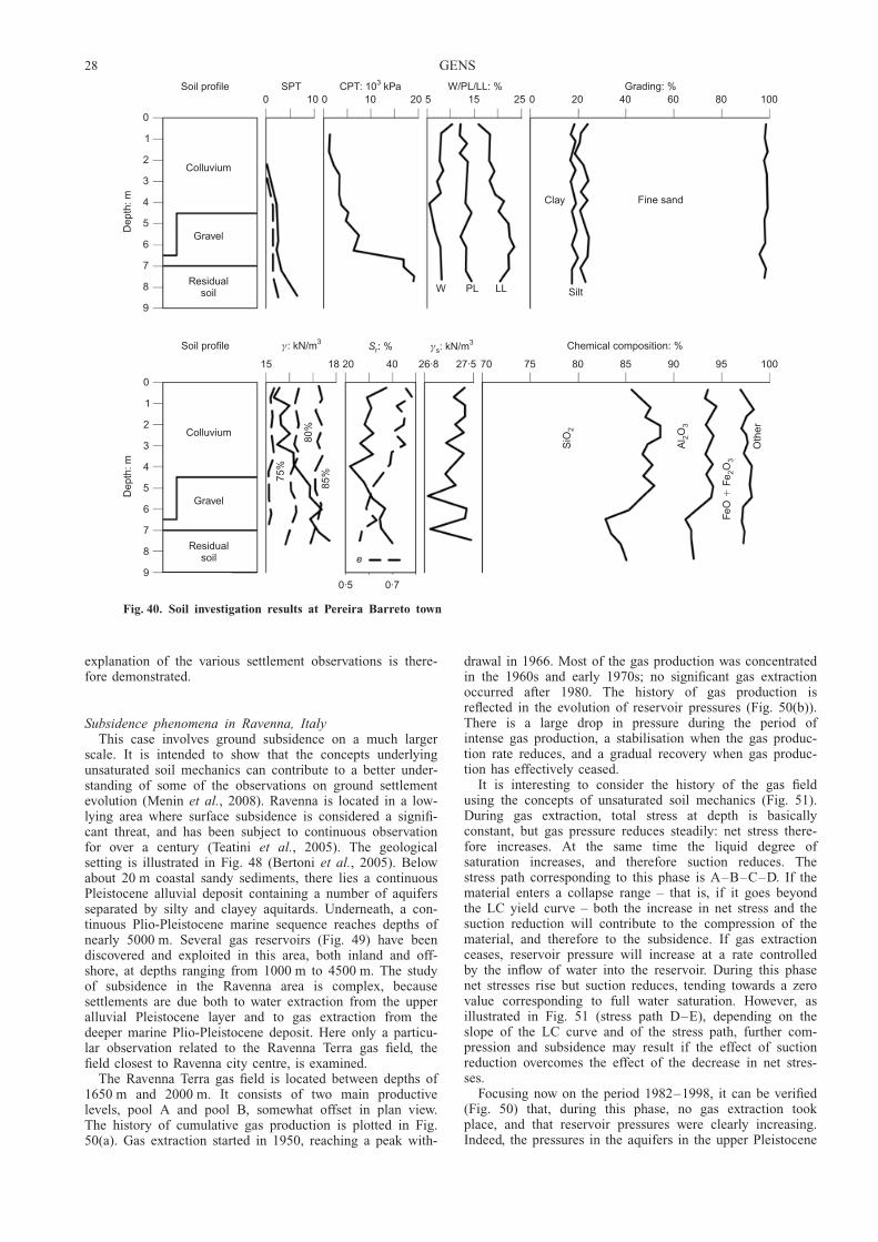
explanation of the various settlement observations is there-fore demonstrated.
Subsidence phenomena in Ravenna, ItalyThis case involves ground subsidence on a much larger
scale. It is intended to show that the concepts underlyingunsaturated soil mechanics can contribute to a better under-standing of some of the observations on ground settlementevolution (Menin et al., 2008). Ravenna is located in a low-lying area where surface subsidence is considered a signifi-cant threat, and has been subject to continuous observationfor over a century (Teatini et al., 2005). The geologicalsetting is illustrated in Fig. 48 (Bertoni et al., 2005). Belowabout 20 m coastal sandy sediments, there lies a continuousPleistocene alluvial deposit containing a number of aquifersseparated by silty and clayey aquitards. Underneath, a con-tinuous Plio-Pleistocene marine sequence reaches depths ofnearly 5000 m. Several gas reservoirs (Fig. 49) have beendiscovered and exploited in this area, both inland and off-shore, at depths ranging from 1000 m to 4500 m. The studyof subsidence in the Ravenna area is complex, becausesettlements are due both to water extraction from the upperalluvial Pleistocene layer and to gas extraction from thedeeper marine Plio-Pleistocene deposit. Here only a particu-lar observation related to the Ravenna Terra gas field, thefield closest to Ravenna city centre, is examined.
The Ravenna Terra gas field is located between depths of1650 m and 2000 m. It consists of two main productivelevels, pool A and pool B, somewhat offset in plan view.The history of cumulative gas production is plotted in Fig.50(a). Gas extraction started in 1950, reaching a peak with-
drawal in 1966. Most of the gas production was concentratedin the 1960s and early 1970s; no significant gas extractionoccurred after 1980. The history of gas production isreflected in the evolution of reservoir pressures (Fig. 50(b)).There is a large drop in pressure during the period ofintense gas production, a stabilisation when the gas produc-tion rate reduces, and a gradual recovery when gas produc-tion has effectively ceased.
It is interesting to consider the history of the gas fieldusing the concepts of unsaturated soil mechanics (Fig. 51).During gas extraction, total stress at depth is basicallyconstant, but gas pressure reduces steadily: net stress there-fore increases. At the same time the liquid degree ofsaturation increases, and therefore suction reduces. Thestress path corresponding to this phase is A–B–C–D. If thematerial enters a collapse range – that is, if it goes beyondthe LC yield curve – both the increase in net stress and thesuction reduction will contribute to the compression of thematerial, and therefore to the subsidence. If gas extractionceases, reservoir pressure will increase at a rate controlledby the inflow of water into the reservoir. During this phasenet stresses rise but suction reduces, tending towards a zerovalue corresponding to full water saturation. However, asillustrated in Fig. 51 (stress path D–E), depending on theslope of the LC curve and of the stress path, further com-pression and subsidence may result if the effect of suctionreduction overcomes the effect of the decrease in net stres-ses.
Focusing now on the period 1982–1998, it can be verified(Fig. 50) that, during this phase, no gas extraction tookplace, and that reservoir pressures were clearly increasing.Indeed, the pressures in the aquifers in the upper Pleistocene
0
1
2
3
4
5
6
7
8
9
Dep
th: m
Colluvium
Gravel
Residualsoil
Soil profile0 10
SPT0 10 20
CPT: 10 kPa3
5 15 25W/PL/LL: %
0 20 40 60 80 100Grading: %
W PL LL
Clay Fine sand
Silt
0
1
2
3
4
5
6
7
8
9
Dep
th: m
Colluvium
Gravel
Residualsoil
Soil profile
15 18
γ: kN/m3
20 40
Sr: %
26·8 27·5 75
γs3: kN/m
80 85 90 95 100
Chemical composition: %
70
0·5 0·7
e
75%
85%
80%
SiO
2
Al
O 23
FeO
FeO
�2
3
Oth
er
Fig. 40. Soil investigation results at Pereira Barreto town
28 GENS

layer appeared to be recovering as well (Brighenti et al.,1994). In spite of this, subsidence continued during thisperiod, albeit at a reduced rate (Fig. 52). A potential causemay be creep phenomena resulting from the previous largesubsidence. However, the shape of the subsidence bowl sug-gests otherwise. The maximum settlements take place in theboundaries of the gas field. The maximum in the centre(point 563) corresponds to the boundary of the upper pool.As the reservoir boundaries are the areas where the waterinflow is highest, it can be argued that those settlements arethe consequence of reservoir flooding, resulting in a suctionreduction. Numerical analyses of the problem yield resultsconsistent with this hypothesis.
Unfortunately, the detailed analysis of the specific situa-tion is too complex to enable firm conclusions to be reachedon the specific role that wetting-induced collapse of some of
the gas field materials plays in the development of theregional subsidence. However, there are tantalising indica-tions (Menin et al., 2008) that that role could be significant,suggesting that an analysis incorporating unsaturated soilmechanics concepts might be required. The confirmation of
Fig. 41. Collapse settlement due to foundation wetting andbuilding damage (Vilar, 2007, personal communication)
340
335
330
325
320
315
Ele
vatio
n: m
Gravel
11/0
7/89
07/0
5/90
03/0
3/91
28/1
2/91
23/1
0/92
19/0
8/93
15/0
6/94
Date(a)
Colluvium
Residualsoil
(b)
0·6 m
76kPa 1·17 m
0
40
80
120
Set
tlem
ent:
mm
330
326
322
318
314
Gro
undw
ate
r le
vel:
m
Groundwater level
S-5
Model
S-3 settlement gauge
Date(c)
08/0
3/90
24/0
9/90
12/0
4/91
29/1
0/91
16/0
5/92
02/1
2/92
20/0
6/93
Fig. 42. Building PB-1, Pereira Barreto town: (a) soil profileand water level elevation; (b) foundation; (c) observed andcomputed foundation settlements
340
335
330
325
320
315
Ele
vatio
n: m
Gravel
11/0
7/89
07/0
5/90
03/0
3/91
28/1
2/91
23/1
0/92
19/0
8/93
15/0
6/94
Date(a)
Colluvium
Residualsoil
(b)
0·9 m
21 kPa0·7 m
0
20
40
60
Set
tlem
ent:
mm
330
326
322
318
314
Gro
undw
ate
r le
vel:
m
Groundwater level
S-9
Model
S-7 settlement gauge
Date(c)
08/0
3/90
25/1
1/90
14/0
8/91
02/0
5/92
19/0
1/93
08/1
0/93
Fig. 43. Building PB-3, Pereira Barreto town: (a) soil profileand water level elevation; (b) foundation; (c) observed andcomputed foundation settlements
SOIL–ENVIRONMENT INTERACTIONS IN GEOTECHNICAL ENGINEERING 29
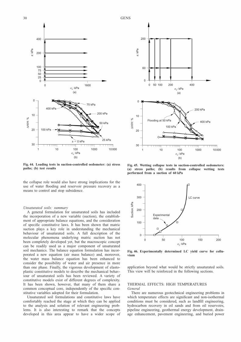
the collapse role would also have strong implications for theuse of water flooding and reservoir pressure recovery as ameans to control and stop subsidence.
Unsaturated soils: summaryA general formulation for unsaturated soils has included
the incorporation of a new variable (suction), the establish-ment of appropriate balance equations, and the considerationof specific constitutive laws. It has been shown that matricsuction plays a key role in understanding the mechanicalbehaviour of unsaturated soils. A full description of themolecular phenomena underlying matric suction has notbeen completely developed yet, but the macroscopic conceptcan be readily used as a major component of unsaturatedsoil mechanics. The balance equation formulation has incor-porated a new equation (air mass balance) and, moreover,the water mass balance equation has been enhanced toconsider the possibility of water and air presence in morethan one phase. Finally, the vigorous development of elasto-plastic constitutive models to describe the mechanical behav-iour of unsaturated soils has been reviewed. A variety ofconstitutive models exist of different degrees of complexity.It has been shown, however, that many of them share acommon conceptual core, independently of the specific con-stitutive variables adopted for their formulation.
Unsaturated soil formulations and constitutive laws havecomfortably reached the stage at which they can be appliedto the analysis and solution of relevant engineering prob-lems. It is also interesting to remark that the conceptsdeveloped in this area appear to have a wider scope of
application beyond what would be strictly unsaturated soils.This view will be reinforced in the following sections.
THERMAL EFFECTS: HIGH TEMPERATURESGeneral
There are numerous geotechnical engineering problems inwhich temperature effects are significant and non-isothermalconditions must be considered, such as landfill engineering,hydrocarbon recovery in oil sands and from oil reservoirs,pipeline engineering, geothermal energy development, drain-age enhancement, pavement engineering, and buried power
400
200
100755025
0
s: k
Pa
0 1600σv: kPa
(a)
0
10
20
30
∆H
/H: %
1 10 100 1000 10000σv: kPa
(b)
400 kPa
100 kPa
75 kPa
200 kPa
50 kPa
25 kPas 0 kPa�
Fig. 44. Loading tests in suction-controlled oedometer: (a) stresspaths; (b) test results
200
60
0
s: k
Pa
0 400σv: kPa
(a)
0
10
20
30
∆H
/H: %
1 10 100 1000 10000σv: kPa
(b)
400 kPa
100 kPa
200 kPa
Flooding at 50 kPa
50 100 200
Fig. 45. Wetting collapse tests in suction-controlled oedometers:(a) stress paths; (b) results from collapse wetting testsperformed from a suction of 60 kPa
400
300
200
100
0
Suc
tion:
kP
a
0 50 100 150 200
σv: kPa
LC curve
Experimentaldata
Fig. 46. Experimentally determined LC yield curve for collu-vium
30 GENS
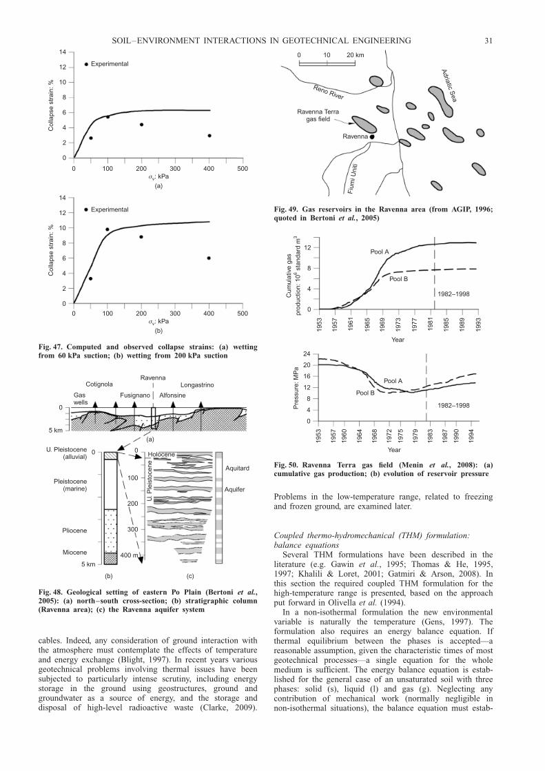
cables. Indeed, any consideration of ground interaction withthe atmosphere must contemplate the effects of temperatureand energy exchange (Blight, 1997). In recent years variousgeotechnical problems involving thermal issues have beensubjected to particularly intense scrutiny, including energystorage in the ground using geostructures, ground andgroundwater as a source of energy, and the storage anddisposal of high-level radioactive waste (Clarke, 2009).
Problems in the low-temperature range, related to freezingand frozen ground, are examined later.
Coupled thermo-hydromechanical (THM) formulation:balance equations
Several THM formulations have been described in theliterature (e.g. Gawin et al., 1995; Thomas & He, 1995,1997; Khalili & Loret, 2001; Gatmiri & Arson, 2008). Inthis section the required coupled THM formulation for thehigh-temperature range is presented, based on the approachput forward in Olivella et al. (1994).
In a non-isothermal formulation the new environmentalvariable is naturally the temperature (Gens, 1997). Theformulation also requires an energy balance equation. Ifthermal equilibrium between the phases is accepted—areasonable assumption, given the characteristic times of mostgeotechnical processes—a single equation for the wholemedium is sufficient. The energy balance equation is estab-lished for the general case of an unsaturated soil with threephases: solid (s), liquid (l) and gas (g). Neglecting anycontribution of mechanical work (normally negligible innon-isothermal situations), the balance equation must estab-
14
12
10
8
6
4
2
0
Col
laps
e st
rain
: %
0 100 200 300 400 500σv: kPa
(a)
Experimental
14
12
10
8
6
4
2
0
Col
laps
e st
rain
: %
0 100 200 300 400 500σv: kPa
(b)
Experimental
Fig. 47. Computed and observed collapse strains: (a) wettingfrom 60 kPa suction; (b) wetting from 200 kPa suction
Ravenna
Gaswells
Cotignola
Fusignano Alfonsine
Longastrino
0
5 km(a)
Aquitard
Aquifer
(c)
Holocene
U. P
leis
toce
ne
0
100
200
300
400 m
0
5 km
U. Pleistocene(alluvial)
Pleistocene(marine)
Pliocene
Miocene
(b)
Fig. 48. Geological setting of eastern Po Plain (Bertoni et al.,2005): (a) north–south cross-section; (b) stratigraphic column(Ravenna area); (c) the Ravenna aquifer system
0 10 20 km
Reno River
Ravenna Terragas field
Ravenna
Fiu
mi U
niti
Adriatic S
ea
Fig. 49. Gas reservoirs in the Ravenna area (from AGIP, 1996;quoted in Bertoni et al., 2005)
12
8
4
0
Cum
ula
tive
gas
prod
uctio
n: 1
0st
anda
rd m
63
Pool A
Pool B
1982–1998
1953
1957
1961
1965
1969
1973
1977
1981
1985
1989
1993
Year
12
8
4
0
Pre
ssur
e: M
Pa
Pool A
Pool B
1982–1998
1953
1957
1960
1964
1968
1972
1979
1983
1987
1990
1994
Year
1975
16
20
24
Fig. 50. Ravenna Terra gas field (Menin et al., 2008): (a)cumulative gas production; (b) evolution of reservoir pressure
SOIL–ENVIRONMENT INTERACTIONS IN GEOTECHNICAL ENGINEERING 31

lish that the change of internal energy of the three soilphases is equal to the net inflow/outflow of heat energy plusany contribution of a sink/source term (Fig. 53). The result-ing expression is
@
@ tEsrs 1 � nð Þ þ ElrlSl n þ EgrgSg nh iþ = � ic þ jEs þ jEl þ jEg
� �¼ f Q
(42)
where E is the specific internal energy, ic is the heat flow byconduction, and jE is the advective energy fluxes. The firstterm of the equation is the change of the internal energy ofthe material, the second one is the net inflow/outflow of heatenergy (expressed in terms of a divergence), and f Q is thesink/source term. Strictly speaking, the addition of a sink/source term contradicts the first law of thermodynamics, andit indicates that the state parameters adopted do not providea complete description of the system (Houlsby & Puzrin,2006). It is used in equation (42) as a matter of conve-nience.
It is accepted that the internal energy for the wholeporous medium is the sum of the internal energies of eachone of the three phases. They can be expressed as
Solid:
Es ¼ csT (43a)
Liquid:
El ¼ cwl ø
wl þ ca
løal
� �T (43b)
Gas:
Eg ¼ cwg T þ l
� �øw
g þ cagø
agT (43c)
where c is the specific heat capacity and l is the specificlatent heat of evaporation/condensation. The specific heatcapacity of liquid water is 4.18 kJ/(kg K) at 258C, thespecific heat of vapour is 1.89 kJ/(kg K) at 1008C, and thespecific heat of air at 258C is 1.01 kJ/(kg K). The variationof these properties over the range of temperatures encoun-tered in most geotechnical problems is small. Becauseequation (42) has been established in terms of internalenergy, the specific heat capacities should be specified atconstant volume. However, these values are very difficult tomeasure in liquids and solids, and so the specific heatcapacities at constant pressure are used instead. For liquidsand solids the difference can be safely neglected. In the caseof gases, the following relationship applies:
cp,m � cv,m ¼ R (44)
where cp,m and cv,m are the specific heat capacity at constantpressure and constant volume respectively, expressed inmolar terms, and R is the gas constant.
The heat flow has several components. The most impor-tant heat transport mechanism, in practically all non-
Elasticdomain
Yield curveLC LCE
A
B
C
D
E
Mean net stress, p
Suc
tion,
()
sp
pg
l�
Fig. 51. Possible stress path during gas extraction (A–B–C–D)and pressure recovery (D–E)
0 5000 10000 15000
Distance: m
0·05
0
0·05
0·10
0·15
0·20
0·25
Sub
side
nce:
m
98–82
98–86
98–92
Ravenna Terrareservoir
196
544
545
546
550
554
555
556
561
563
562
495
496
497
353
355
336
337
Fig. 52. Subsidence above the Ravenna Terra gas field duringthe period 1982–1998 (Menin et al., 2008)
Net flow of energyin gas:
jEg
Energy in gas:
E S ng g g�
Net flow of energyin mineral:
jEs
Net flow of energyin liquid:
jEl
Net flow of energyby conduction
ic
Energy in mineral:
(1 )E ns s� �
Energy in liquid:
E S nl l l�
Fig. 53. Scheme to establish the equation for energy balance for an unsaturated soil
32 GENS

isothermal problems, is conduction ic, but for completenessthe advective contributions due to the movement of the solid,liquid and gas phases are also included, as follows.
jEs ¼ Esrs 1 � nð Þ _u (45a)
jEl ¼ j9lw Ew
l þ j9la Ea
l þ ElrlSl n _u (45b)
jEg ¼ j9gw Ew
g þ j9ag Eag þ EgrgSg n _u (45c)
where j9 is the flow of the corresponding fluid phase withrespect to the solid phase.
Summarising, the coupled THM formulation involves thefollowing balance equations: water mass (equation (15)), airmass (equation (16)), solid mass (equation (17)), energy(equation (42)) and momentum (equilibrium) (equation(18)). As in the HM formulation, it is possible, using theconcept of material derivative, to eliminate the equation ofsolid mass balance (Olivella et al., 1994). The process issummarised here. The material derivative is defined as
Ds dð ÞDt
¼ @ dð Þ@ t
þ du
dt� = dð Þ (46)
and the solid mass balance equation (equation (17)) becomes
Ds n
Dt¼ 1
Łs
1 � nð Þ DsŁs
Dt
� þ 1 � nð Þ= � du
dt(47)
and can be incorporated in the other mass and energybalance equations, resulting in the following.
Water mass balance:
nDs Łw
l Sl þ Łwg Sg
� �Dt
þ Łwl Sl þ Łw
g Sg
� � Ds n
Dt
þ Łwl Sl þ Łw
g Sg
� �n
� �= � du
dtþ = � j9wl þ j9wg
� �¼ f w
(48)
Air mass balance:
nDs Ła
l Sl þ ŁagSg
� �Dt
þ Łal Sl þ Ła
gSg
� � Ds n
Dt
þ Łal Sl þ Ła
gSg
� �n
� �= � du
dtþ = � j9al þ j9ag
� �¼ f a
(49)
Energy balance:
nDs ElrlSl þ EgrgSg
� �Dt
þ 1 � nð Þ Ds Esrsð ÞDt
þ ElrlSl þ EgrgSg
� �= � du
dt
þ = � ic þ j9Es þ j9El þ j9Eg
� �¼ f E
(50)
Momentum balance (equilibrium):
= � �t þ b ¼ 0 (51)
The complete set of equations to be solved in the coupledTHM formulation described comprises equations (48), (49),(50) and (51). The equilibrium equation is unchanged; it hasbeen included again here for completeness. More informa-tion on the transformation of the HM formulation into aTHM formulation is given in Gens et al. (1997).
Coupled THM formulation: constitutive equationsThermal and hydraulic behaviour. The effect of temperatureis pervasive throughout most physical processes, and conse-quently temperature enters the definition of constitutive lawswhen used in a non-isothermal context. New constitutive lawsare also required to address specific thermal phenomena
(Table 1). For instance, heat conduction is assumed to begoverned by Fourier’s law,
ic ¼ �º Tð Þ=T (52)
where º is the thermal conductivity. In a multiphase med-ium, thermal conductivity will be some kind of average ofthe thermal conductivities of the phases that will depend onthe microstructural arrangement of material. If the phasearrangement was in series, the harmonic mean would apply;alternatively, if the phase arrangement was in parallel, thearithmetic mean would be appropriate. For an intermediatesituation the geometric mean weighed by volumetric frac-tions often provides an adequate estimate:
º ¼ º1�ns ºSl n
l º 1�Slð Þng
¼ ºS l
satº1�Sl
dry
(53)
The thermal conductivities of most of the usual substancesmaking up the solid phase of soils have a limited range ofvalues (with the exception of quartz). Therefore the thermalconductivities of saturated soils are usually in the range1–3 W/(m K)—a very narrow range compared with that ofhydraulic conductivity. The thermal conductivity of liquidwater is 0.6 W/(m K) at 258C. In the gas phase much lowervalues apply: the thermal conductivity of water vapour is0.016 W/(m K) at 1008C, and of air is 0.024 W/(m K) at258C. Therefore the degree of saturation of the soil has amajor impact on the thermal conductivity of an unsaturatedporous medium. Although there is some dependence ontemperature itself, it is generally minor when compared withthe influence of water content or degree of saturation. Fig.54 shows experimental measurements of thermal conductiv-ity on compacted Febex bentonite (Villar, 2002): the effectof degree of saturation is readily apparent. The geometricmean expression (equation (53)) provides a reasonableagreement with observations.
As noted before, the advective flows of liquid and gas, ql
and qg, are governed by Darcy’s law (equations (19) and(20)). Accordingly, temperature-induced viscosity variationsshould result in corresponding variations of hydraulic con-ductivity. For reference, the viscosity of water at 208C is1 Pa s, but drops gradually to 0.28 Pa s at 1008C, a signifi-cant difference.
1·60
1·40
1·20
1·00
0·80
0·60
0·40
0·20
The
rmal
con
duct
ivity
: W/m
°C
Measurements
Model
0 0·20 0·40 0·60 0·80 1·00
Degree of saturation
Fig. 54. Variation of the thermal conductivity of Febex bento-nite with degree of saturation (Villar, 2002): the prediction ofthe geometric mean expression (equation (53)) is plotted forcomparison
SOIL–ENVIRONMENT INTERACTIONS IN GEOTECHNICAL ENGINEERING 33
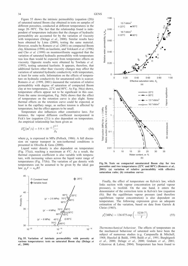
Figure 55 shows the intrinsic permeability (equation (20))of saturated natural Boom clay obtained in tests on samples ofdifferent porosities, conducted at different temperatures in therange 20–908C. The fact that the relationship found is inde-pendent of temperature indicates that the changes of hydraulicpermeability are accounted for by the variation of viscositywith temperature (Delage et al., 2000). Similar results havebeen obtained by Lima (2009), testing the same material.However, results by Romero et al. (2001) on compacted Boomclay, Khemissa (1998) on kaolinite, and Volckaert et al. (1996)and Cho et al. (1999) on montmorillonite suggested that thevariation of saturated hydraulic permeability with temperaturewas less than would be expected from temperature effects onviscosity. Opposite results were obtained by Towhata et al.(1993), testing saturated kaolinite. It appears, therefore, thatadditional factors other than viscosity changes may affect thevariation of saturated hydraulic conductivity with temperature,at least for some soils. Information on the effects of tempera-ture on hydraulic conductivity for unsaturated soils is scarcer.Romero et al. (1999, 2001) measured the variation of relativepermeability with degree of saturation of compacted Boomclay at two temperatures, 228C and 808C. As Fig. 56(a) shows,temperature effects appear not to be significant in this case.From the same investigation, Fig. 56(b) shows that the effectof temperature on the retention curve is also slight. Somethermal effects on the retention curve could be expected, atleast in the capillary range, as surface tension is affected bytemperature, but the effect appears to be small.
Temperature also influences other constitutive laws. Forinstance, the vapour diffusion coefficient incorporated inFick’s law (equation (21)) is also dependent on temperature.An empirical relationship has been given as
Dwm m2=s� �
¼ 5:9 3 10�12 T 2:3
pg
(54)
where pg is expressed in MPa (Pollock, 1986). A full discus-sion on vapour transport in non-isothermal conditions ispresented in Olivella & Gens (2000).
Liquid water density is also dependent on temperature(Fig. 57(a)), reaching a maximum at 48C. As a result, thethermal expansion coefficient is also variable with tempera-ture, with increasing values across the liquid water range oftemperatures (Fig. 57(b)). The variation of gas density withtemperatures can be assumed to be given by the ideal gaslaw: pgV ¼ nmRT.
Finally, the effect of temperature on Kelvin’s law, whichlinks suction with vapour concentration (or partial vapourpressure), is twofold. On the one hand, it enters thedenominator of the correction term in Kelvin’s law (equation(8)). But the equilibrium vapour pressure (and thereforeequilibrium vapour concentration) is also dependent ontemperature. The following expression gives an adequateestimation of the variation, based on data from Garrels &Christ (1965).
p0v MPað Þ ¼ 136:075 exp � 5239:7
T
� �(55)
Thermomechanical behaviour. The effects of temperature onthe mechanical behaviour of saturated soils have been thesubject of numerous studies (e.g. Campanella & Mitchell,1968; Hueckel & Baldi, 1990; Baldi et al., 1991; Burghignoliet al., 2000; Delage et al., 2000; Graham et al., 2001;Cekerevac & Laloui, 2004). Temperature has been found to
Constant head
Variable head
45
40
35
30
20°C
80°C
90°C
60°C
60°C
60°C
70°C
90°C
70°C
70°C
45°C
40°C30°C
30°C
20°C( 2·5 MPa)p� �
( 4 MPa)p� �
( 6 MPa)p� �
10�20 10�19 10�18
k: m2
Por
osity
: %
Fig. 55. Variation of intrinsic permeability with porosity atvarious temperatures: tests on saturated Boom clay (Delage etal., 2000)
1·00
0·80
0·60
0·40
0·20
0
0 0·20 0·40 0·60 0·80 1·00
Rel
ativ
e w
ate
r pe
rmea
bilit
y,/
kk
ww
s
Effective saturation ratio, Se
13·7 kN/m3
16·7 kN/m3
22°C 80°C
80°C22°C
(a)
10
1
0·1
0·01
5 10 15 20 25 30 35
Tota
l suc
tion
(MP
a) fo
r3
MP
aψ
�
Ma
tric
suc
tion
(MP
a) fo
r0·
45 M
Pa
s�
22°C80°C
13·7 kN/m3
16·7 kN/m3
Water content, : %w(b)
Air
over
pres
sure
Vap
our
equi
libriu
mFig. 56. Tests on compacted unsaturated Boom clay for twoporosities and two temperatures (228C and 808C) (Romero et al.,2001): (a) variation of relative permeability with effectivesaturation ratio; (b) retention curves
34 GENS
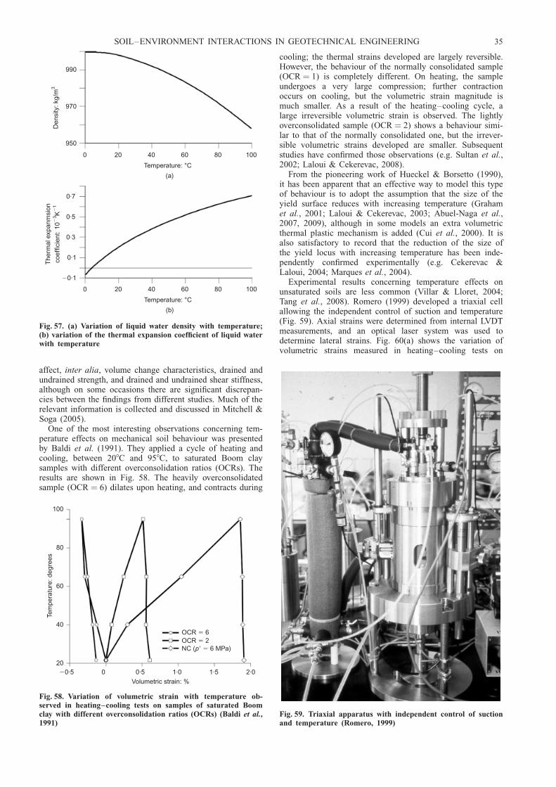
affect, inter alia, volume change characteristics, drained andundrained strength, and drained and undrained shear stiffness,although on some occasions there are significant discrepan-cies between the findings from different studies. Much of therelevant information is collected and discussed in Mitchell &Soga (2005).
One of the most interesting observations concerning tem-perature effects on mechanical soil behaviour was presentedby Baldi et al. (1991). They applied a cycle of heating andcooling, between 208C and 958C, to saturated Boom claysamples with different overconsolidation ratios (OCRs). Theresults are shown in Fig. 58. The heavily overconsolidatedsample (OCR ¼ 6) dilates upon heating, and contracts during
cooling; the thermal strains developed are largely reversible.However, the behaviour of the normally consolidated sample(OCR ¼ 1) is completely different. On heating, the sampleundergoes a very large compression; further contractionoccurs on cooling, but the volumetric strain magnitude ismuch smaller. As a result of the heating–cooling cycle, alarge irreversible volumetric strain is observed. The lightlyoverconsolidated sample (OCR ¼ 2) shows a behaviour simi-lar to that of the normally consolidated one, but the irrever-sible volumetric strains developed are smaller. Subsequentstudies have confirmed those observations (e.g. Sultan et al.,2002; Laloui & Cekerevac, 2008).
From the pioneering work of Hueckel & Borsetto (1990),it has been apparent that an effective way to model this typeof behaviour is to adopt the assumption that the size of theyield surface reduces with increasing temperature (Grahamet al., 2001; Laloui & Cekerevac, 2003; Abuel-Naga et al.,2007, 2009), although in some models an extra volumetricthermal plastic mechanism is added (Cui et al., 2000). It isalso satisfactory to record that the reduction of the size ofthe yield locus with increasing temperature has been inde-pendently confirmed experimentally (e.g. Cekerevac &Laloui, 2004; Marques et al., 2004).
Experimental results concerning temperature effects onunsaturated soils are less common (Villar & Lloret, 2004;Tang et al., 2008). Romero (1999) developed a triaxial cellallowing the independent control of suction and temperature(Fig. 59). Axial strains were determined from internal LVDTmeasurements, and an optical laser system was used todetermine lateral strains. Fig. 60(a) shows the variation ofvolumetric strains measured in heating–cooling tests on
(a)
0 20 40 60 80 100
Temperature: °C
(b)
0 20 40 60 80 100
Temperature: °C
The
rmal
exp
anm
sion
coef
ficie
nt: 1
0K
��
31
0·7
0·5
0·3
0·1
�0·1
990
970
950
Den
sity
: kg/
m3
Fig. 57. (a) Variation of liquid water density with temperature;(b) variation of the thermal expansion coefficient of liquid waterwith temperature
100
80
60
40
20
Tem
pera
ture
: deg
rees
�0·5 0 0·5 1·0 1·5 2·0
Volumetric strain: %
OCR 6�
OCR 2�NC ( 6 MPa)p� �
Fig. 58. Variation of volumetric strain with temperature ob-served in heating–cooling tests on samples of saturated Boomclay with different overconsolidation ratios (OCRs) (Baldi et al.,1991)
Fig. 59. Triaxial apparatus with independent control of suctionand temperature (Romero, 1999)
SOIL–ENVIRONMENT INTERACTIONS IN GEOTECHNICAL ENGINEERING 35
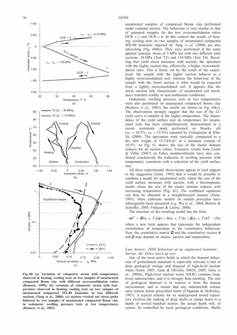
unsaturated samples of compacted Boom clay performedunder constant suction. The behaviour is very similar to thatof saturated samples for the two overconsolidation ratiosOCR ¼ 1 and OCR ¼ 6. In this context the results of heat-ing–cooling tests on two samples of unsaturated compactedMX-80 bentonite reported by Tang et al. (2008) are alsointeresting (Fig. 60(b)). They were performed at the sameapplied isotropic stress of 5 MPa but with two different totalsuctions, 39 MPa (Test T5) and 110 MPa (Test T4). Recal-ling that yield stress increases with suction, the specimenwith the higher suction has, effectively, a higher overconsoli-dation ratio. This is borne out by the result of the experi-ment: the sample with the higher suction behaves as ahighly overconsolidated soil, whereas the behaviour of thesample with the lower suction is what would be expectedfrom a lightly overconsolidated soil. It appears that thestress–suction link characteristic of unsaturated soil mech-anics transfers readily to non-isothermal conditions.
Oedometer swelling pressure tests at two temperatureswere also performed on unsaturated compacted Boom clay(Romero et al., 2003): the results are shown in Fig. 60(c).The observations strongly suggest that the size of the LCyield curve is smaller at the higher temperature. The depen-dence of the yield surface size on temperature for unsatu-rated soils has been comprehensively demonstrated in arecent systematic study performed on Bourke silt(wL ¼ 20.5%, wP ¼ 15.5%) reported by Uchaipichat & Kha-lili (2009). The specimens were statically compacted to adry unit weight of 15.3 kN/m3 at a moisture content of10.5%. As Fig. 61 shows, the size of the elastic domainreduces for all suction values. Extensive results from Lloret& Villar (2007) on Febex montmorillonite have also con-firmed conclusively the reduction of swelling pressure withtemperature, consistent with a reduction of the yield surfacesize.
All these experimental observations appear to lend supportto the suggestion (Gens, 1995) that it would be possible tocombine a model for unsaturated soils, where the size of theyield surface increases with suction, with a thermoplasticmodel where the size of the elastic domain reduces withincreasing temperature (Fig. 62). The combined equationscan then be obtained in a straightforward manner (Gens,1995). More elaborate models on similar principles havesubsequently been presented (e.g. Wu et al., 2004; Bolzon &Schrefler, 2005; Francois & Laloui, 2008).
The structure of the resulting model has the form
d�� ¼ D �, s, Tð Þ(d�) þ h �, s, Tð Þds þ � �, s, Tð ÞdT (56)
where a new term appears that represents the independentcontribution of temperature to the constitutive behaviour.Now, the constitutive matrix D and the constitutive vectors hand � may depend on strains, suction and temperature.
Case history: THM behaviour of an engineered bentonitebarrier, the Febex mock-up test
One of the most active fields in which the thermal behav-iour of geotechnical materials is especially relevant is that ofdeep geological storage and disposal of high-level nuclearwaste (Gens, 2003; Gens & Olivella, 2001b, 2005; Gens etal., 2009a). High-level nuclear waste (HLW) contains long-lived radionuclides, and it is strongly heat emitting. The aimof geological disposal is to remove it from the humanenvironment, and to ensure that any radionuclide releaserates remain below prescribed limits (Chapman & McKinley,1987). A typical scheme for an underground mined reposi-tory involves the sinking of deep shafts or ramps down to adepth of several hundred metres: the actual depth will, ofcourse, be controlled by local geological conditions. Shafts
�1·00
�0·50
0
0·50
1·00
1·50
2·00
Vol
umet
ric s
trai
n,: %
ε v
20 30 40 50 60Temperature, : °CT
(a)
OCR 6�
σm a 0·10 MPa� �u
σm a 1·00 MPa� �u
OCR 1�
?
N.C. sample
90
80
70
60
50
40
30
20
Tem
pera
ture
: °C
T5 ( 39 MPa)St �
T4 ( 110 MPa)St �
Cooling Cooling
Heating
Heating
Dilation Contraction
�1·00 �0·50 0 0·50 1·00 1·50Volumetric strain: %
(b)
1
0·1
0·01
Suc
tion,
: MP
as
A
B
Equilibrium stages
22°C
80°C
0 0·05 0·10 0·15 0·20 0·25Vertical net stress, : MPaσv a� u
(c)
C
Fig. 60. (a) Variation of volumetric strain with temperatureobserved in heating–cooling tests on two samples of unsaturatedcompacted Boom clay with different overconsolidation ratios(Romero, 1999); (b) variation of volumetric strain with tem-perature observed in heating–cooling tests on two samples ofunsaturated compacted MX-80 bentonite at two differentsuctions (Tang et al., 2008); (c) suction–vertical net stress pathsfollowed by two samples of unsaturated compacted Boom clayin oedometer swelling pressure tests at two temperatures(Romero et al., 2003)
36 GENS
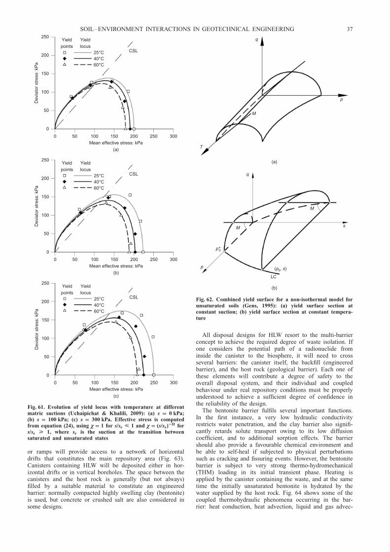
or ramps will provide access to a network of horizontaldrifts that constitutes the main repository area (Fig. 63).Canisters containing HLW will be deposited either in hor-izontal drifts or in vertical boreholes. The space between thecanisters and the host rock is generally (but not always)filled by a suitable material to constitute an engineeredbarrier: normally compacted highly swelling clay (bentonite)is used, but concrete or crushed salt are also considered insome designs.
All disposal designs for HLW resort to the multi-barrierconcept to achieve the required degree of waste isolation. Ifone considers the potential path of a radionuclide frominside the canister to the biosphere, it will need to crossseveral barriers: the canister itself, the backfill (engineeredbarrier), and the host rock (geological barrier). Each one ofthese elements will contribute a degree of safety to theoverall disposal system, and their individual and coupledbehaviour under real repository conditions must be properlyunderstood to achieve a sufficient degree of confidence inthe reliability of the design.
The bentonite barrier fulfils several important functions.In the first instance, a very low hydraulic conductivityrestricts water penetration, and the clay barrier also signifi-cantly retards solute transport owing to its low diffusioncoefficient, and to additional sorption effects. The barriershould also provide a favourable chemical environment andbe able to self-heal if subjected to physical perturbationssuch as cracking and fissuring events. However, the bentonitebarrier is subject to very strong thermo-hydromechanical(THM) loading in its initial transient phase. Heating isapplied by the canister containing the waste, and at the sametime the initially unsaturated bentonite is hydrated by thewater supplied by the host rock. Fig. 64 shows some of thecoupled thermohydraulic phenomena occurring in the bar-rier: heat conduction, heat advection, liquid and gas advec-
250
200
150
100
50
0
Dev
iato
r st
ress
: kP
aYieldpoints
Yieldlocus
25°C40°C60°C
0 50 100 150 200 250 300
Mean effective stress: kPa
(a)
CSL
250
200
150
100
50
0
Dev
iato
r st
ress
: kP
a
Yieldpoints
Yieldlocus
25°C40°C60°C
0 50 100 150 200 250 300
Mean effective stress: kPa
(b)
CSL
250
200
150
100
50
0
Dev
iato
r st
ress
: kP
a
Yieldpoints
Yieldlocus
25°C40°C60°C
0 50 100 150 200 250 300
Mean effective stress: kPa
(c)
CSL
Fig. 61. Evolution of yield locus with temperature at differentmatric suctions (Uchaipichat & Khalili, 2009): (a) s 0 kPa;(b) s 100 kPa; (c) s 300 kPa. Effective stress is computedfrom equation (24), using � 1 for s/se < 1 and � (s/se)2� fors/se > 1, where se is the suction at the transition betweensaturated and unsaturated states
q
T
M
p
(a)
q
M
M
p
p*0
( , )p s0
LC
(b)
s
Fig. 62. Combined yield surface for a non-isothermal model forunsaturated soils (Gens, 1995): (a) yield surface section atconstant suction; (b) yield surface section at constant tempera-ture
SOIL–ENVIRONMENT INTERACTIONS IN GEOTECHNICAL ENGINEERING 37

tive flow, vapour diffusion and phase changes (evaporation/condensation). In addition there are associated mechanicaleffects linked to the wetting and drying of the unsaturatedbentonite. Interaction with the host rock adds additionalcomplexity to the system (Gens et al., 2002a). Although allthe phenomena identified are in fact included in the formula-tion outlined above, the THM behaviour of the engineeredbentonite barrier provides a very comprehensive test of itsapplicability to a real engineering problem.
The issue of HLW disposal is sufficiently important towarrant the performance of full-scale tests simulating reposi-tory conditions. These tests are usually conducted in spe-cially built underground laboratories: there are several ofthem in Europe and elsewhere (Gens, 2003). The Febex test
was an experimental programme led by the Spanish agencyfor radioactive waste (Enresa) to advance understanding ofthe THM behaviour of the engineered bentonite barrier. Itincluded a full-scale in situ test carried out at the Grimseltest site, an underground laboratory excavated in granite inthe Swiss Alps. The test and its associated modelling aredescribed in Gens et al. (1998, 2009b). However, attention isinstead focused here on the mock-up test, an experimentconstructed to a similar scale but performed under morecontrolled conditions at the Ciemat laboratory in Madrid. Afull description of the overall project is given in Huertas etal. (2006).
The mock-up test (Fig. 65) simulates an engineeredbarrier made up of blocks of compacted swelling clay being
1
1
2
2
23
3
SurfaceinstallationsDetails of disposal facility
Host rock
Bentonite backfill
Cask
Access shaft
Drifts
Fig. 63. Scheme of a deep geological repository for high-level nuclear waste
Heat in Heat
Water
Heat out
Water in
GasVapour flux (diffusion)
Heat flux(conduction and advection)
Waterevaporation
Watercondensation
Solid
Heat flux (conduction)
LiquidLiquid flux (advection)
Heat flux(conduction and advection)
Solid
Heat flux (conduction)
Liquid
Liquid flux (advection)
Heat flux(conduction and advection)
Bentonite barrier Host rock
Fig. 64. Scheme of thermo-hydraulic processes occurring in the bentonite barrier and immediately adjacent rock
38 GENS

subject to heating and hydration simultaneously. The clay isa bentonite (wL ¼ 98–106, wP ¼ 50–56), obtained from aquarry in southern Spain. It has high smectite content, in therange 88–96%, and the cation exchange capacity is 100–102 meq/100 g (42% Ca, 33% Mg, 23% Na, 2% K). Thebentonite blocks were compacted at a water content of13.6%, and the average dry density of the barrier (includinggaps) is 1.65 Mg/m3. The initial degree of saturation was0.715.
The barrier is enclosed in a cylindrical steel body with aninner length of 6.00 m and an inner diameter of 1.62 m,designed to resist the swelling pressures that develop duringthe test. The dimensions of the experiment are of the sameorder as in the real system, where the envisaged diameter ofthe barrier is 2.28 m. More significantly, the thickness of thebarrier, 66 cm, is very close to the design one. Two heatersare installed in the axis of the barrier to mimic the heatingaction of the nuclear HLW. The hydration system supplies
water uniformly to the periphery of the barrier through ageotextile placed around the outer boundary of the barrier,and the amount of water entering the barrier is carefullymonitored by weight. The test was intensively instrumentedfor temperature, relative humidity (equivalent to total suc-tion), liquid pressure and total pressure in 24 sections alongthe barrier. A useful feature of the test is that it is symmet-rical with respect to the central section: therefore observa-tions made in sections located at equal distances from thecentre should be very similar. This feature provides a veryconvenient method to assess the reliability of the test results.
The test is temperature controlled: the highest temperaturein the contact between heater and clay is kept at 1008C. Thisis a barrier design requirement designed mainly to avoidmineralogical changes in the bentonite; in fact, the coupledformulation can deal with temperatures higher than 1008Cwithout requiring any modification (Olivella & Gens, 2000).Water was supplied at a constant 0.55 MPa pressure. Be-
(a) (b)
Printer
Backup
Data PC
RS232CserialcommunicationRS232C
serialcommunication
Control PC
Programmablelogiccontrol
DAS HELIOSN2 pressure line
Pressurecontrol
Weighing Weighing
Signal I/OsPower and signal I/Os
Backfilling material
Heater Heater
Pressurised water line(c)
Fig. 65. Febex mock-up test: (a) heater installation; (b) view of the experiment; (c) schematic representation of the maincomponents of the experiment
SOIL–ENVIRONMENT INTERACTIONS IN GEOTECHNICAL ENGINEERING 39

cause of the very low permeability of the bentonite, it isnecessary to run the test for a very long period of time.Heaters were switched on in February 1997, and the test isstill continuing at present. Herein results are given for thefirst 3421 days of the experiment.
Test observations for the entire duration of the test werepredicted at the beginning of the experiment based on theinformation available at the time: the analysis was labelledOBC (Operational Base Case). To represent the behaviour ofthe unsaturated compacted clay, the BBM was adopted witha modified elastic component to account for the highlyswelling properties of the clay on wetting, as well as theeffects of temperature. Full details of all modelling activitiesare provided in Sanchez & Gens (2006).
Measured and computed temperatures at four differentdistances from the barrier axis are shown in Fig. 66 forsections in front of the heaters (hot sections) and away fromthe heaters (cool sections). Temperatures are practically
constant throughout the test; predictions are in good agree-ment with observations for the two types of section. This isnot surprising, as heat transport is essentially by conduction;a good estimate of thermal conductivity (Fig. 54) and theuse of realistic boundary conditions ensure good correspon-dence between predictions and measurements, especially in atemperature-controlled test. Heater power requirements arealso satisfactorily predicted.
The hydraulic behaviour of the barrier is shown in termsof the evolution of relative humidity with time in Fig. 67.Again the results for hot sections (Fig. 67(a)) and coolsections (Fig. 67(b)) are presented. Four points of the hotsections at different distances from the test axis are consid-ered: 0.22 m (close to the heaters), 0.37 m, 0.55 m (inter-mediate points) and 0.70 m (close to the outer hydrationboundary). They correspond to the locations of the capaci-
Section 5z 1·185 m�
Section 11z 2·685 m�
(a)
(b)
0 500 1000 1500 2000 2500 3000 3500Time: days
0
10
20
30
40
50
60
70
80
90
100
r 0·20 m�
r 0·39 m�
r 0·58 m�
r 0·77 m�
0 500 1000 1500 2000 2500 3000 3500Time: days
10
20
30
40
50
60
70
80
90
100
Tem
pera
ture
: °C
Tem
pera
ture
: °C
r 0·22 m�
r 0·39 m�
r � 0·58 m
r 0·77 m�
Fig. 66. Temperatures in the Febex mock-up test (observed andcomputed values): (a) sections A5–B5 in front of the heaters(hot sections); (b) sections A11–B11 away from the heaters (coolsections)
TestSection 10. : mr
0·350
0·665
Model
Duo
OBC
0 500 1000 1500 2000 2500 3000 350010
20
30
40
50
60
70
80
90
100
Rel
ativ
e hu
mid
ity: %
0 500 1000 1500 2000 2500 3000 350010
20
30
40
50
60
70
80
90
100
Rel
ativ
e hu
mid
ity: %
Test
Section 4. : mr
0·37
0·70
0·22
0·55
Model
OBC
Duo
Time: days
(a)
Time: days
(b)
Fig. 67. Relative humidity in the Febex mock-up test (observedand computed values): a) sections A4–B4 in front of the heaters(hot sections); (b) sections A10–B10 away from the heaters (coolsections)
40 GENS

tive relative humidity sensors. The point closest to the heaterundergoes an initial severe drying, followed by a moregradual subsequent hydration. Also, before the onset ofdrying, a temporary increase in relative humidity is detected:this is due to the passage of a vapour front coming from theinnermost part of the barrier. Modelling successfully cap-tures the three stages—temporary hydration by vapour,strong drying and final hydration—demonstrating that thephenomena of evaporation, condensation and vapour migra-tion are well reproduced. The same behaviour, albeit in amore muted form, is observed at a distance of 0.37 m fromthe axis, both in the test and in the modelling. In contrast, atthe points closer to the hydration boundary (0.55 m and0.70 m), only a steady progress of hydration is measuredand modelled. A continuous increase of relative humidity isalso the behaviour exhibited by the cool sections (Fig.67(b)). The outlier results obtained on day 1381 and imme-diately afterwards are the consequence of an unplannedoverheating event that occurred on that day.
From Fig. 67(a), it is also apparent that the OBC predic-tions of relative humidity are very satisfactory up to day 900or so; subsequently there is an increasing departure ofpredictions from observations. This lack of agreement forlater times is confirmed by the observation of a globalhydration variable, the total amount of water entering thebentonite barrier (Fig. 68(a)); differences are also apparentfrom about day 900 or so. It is evident that the OBC modelfails to reproduce correctly the long-term behaviour of thetest. Fig. 68(b) shows the development of radial pressures toquite high values of several MPa, owing to the hydration-induced swelling of the bentonite. The OBC analysis over-estimates the long-term radial stresses, although inevitably,in the case of stress measurements, observation scatter islarger. Also, stresses were more strongly affected by theoverheating episode.
A closer examination of the problem showed that themissing factor in the analysis was consideration of the evolu-tion of the microstructure during the test. With the standardformulation, intrinsic permeability depends only on porosity,but in fact it depends more strongly on pore size and porestructure. In this test the variations of porosity are not large,because of the confinement provided by the heaters and steelcontainer: the experiment is similar to a swelling pressuretest. However, compacted bentonite has a very changeablemicrostructure. This is illustrated in Fig. 69, where micro-graphs of compacted Febex bentonite, obtained in the envir-onmental scanning electron microscope, are shown for itsinitial state, for a partially hydrated condition, and for thefinal saturation state. Initially, the clay particles are clumpedtogether in large aggregates, leaving large inter-aggregatepores between them. Intrinsic permeability is therefore high.However, as hydration advances, aggregates swell and pro-gressively occupy the large pores. The consequence is that amatrix-dominated fabric takes over, with much smaller poresand a much reduced intrinsic permeability.
Fortunately a model for expansive clays was available(Gens & Alonso, 1992; Alonso et al., 1999) that allows theseparate, but interdependent, consideration of the two struc-tures identified in the material: a macrostructure made up ofa quasi-granular fabric of aggregates and large pores, and amicrostructure related to the clay particles and the physico-chemical phenomena occurring at that level (Fig. 70). Themodel attempts to resolve the paradox that the physicochem-ical phenomena underlying expansive clay behaviour arelargely reversible, whereas the overall soil behaviour in-volves large amounts of irreversible strains. The BBM isused to model the behaviour of the macrostructure, and therelationship between the two levels is provided by appropri-ate interaction functions. The model has been formulated
mathematically in terms of a generalised plasticity frame-work (Sanchez et al., 2005).
This constitutive model was adopted as a key componentof a new analysis labelled ‘Duo’. As it is now possible totrack the evolution of macrostructure and microstructure, theintrinsic permeability is made dependent on macrostructureporosity alone. As shown in Figs 67 and 68, the results ofthe Duo analysis are much closer to observations, especiallyin the long term. It must be concluded that, in this case, aproper consideration of the fabric of the material and itsmodification by hydration is essential to achieve a goodreproduction of the long-term behaviour of the barrier. It isa powerful reminder of the importance of taking microstruc-tural features into account in the analysis of the problem.
Case history: THM response of an argillaceous hostmedium, the HE-D test
Beyond the engineered barrier of a HLW disposal scheme,there lies the geological host medium, the behaviour of
(a)
(b)
0 500 1000 1500 2000 2500 3000 3500
Time: days
0
2
4
6
8R
adia
l str
ess:
MP
a
Test
Section 3
Section 6
Model
OBC
Duo
0 500 1000 1500 2000 2500 3000
Time: days
0
200
400
600
800
1000
1200
Wa
ter
inta
ke: k
g
Water intake
Test
OBC model
Duo model
Fig. 68: (a) Water intake in the Febex mock-up test (observedand computed values): (b) radial stresses in sections A3–B3, infront of the heaters (observed and computed values)
SOIL–ENVIRONMENT INTERACTIONS IN GEOTECHNICAL ENGINEERING 41
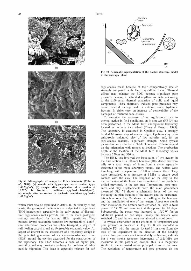
which must also be examined in detail. In the vicinity of thewaste, the geological medium is also subjected to significantTHM interactions, especially in the early stages of disposal.Soft argillaceous rocks provide one of the main geologicalsettings considered for hosting HLW repositories. Theypossess several favourable features: low permeability, signifi-cant retardation properties for solute transport, a degree ofself-healing capacity, and no foreseeable economic value. Anaspect of interest in the assessment of a repository design isthe potential generation of an excavation-damaged zone(EDZ) around the cavities excavated for the construction ofthe repository. The EDZ becomes a zone of higher per-meability, and may provide a pathway for preferential radio-nuclide migration. This issue is especially relevant for soft
argillaceous rocks because of their comparatively smallerstrength compared with hard crystalline rocks. Thermaleffects may enhance the EDZ, because significant porepressures develop in saturated argillaceous materials owingto the differential thermal expansion of solid and liquidcomponents. These thermally induced pore pressures maycause material damage and, in extreme cases, hydraulicfracture. In either case, an increase of permeability of thedamaged or fractured zone ensues.
To examine the response of an argillaceous rock tothermal action in field conditions, an in situ test (HE-D) hasbeen performed in the Mont Terri underground laboratorylocated in northern Switzerland (Thury & Bossart, 1999).The laboratory is excavated in Opalinus clay, a stronglybedded Mesozoic clay of marine origin. Opalinus clay is ananisotropic indurated clay of low porosity and, for anargillaceous material, significant strength. Some typicalparameters are collected in Table 3: several of them dependon the orientation with respect to bedding. The overburdendepth at the location of the Mont Terri laboratory variesbetween 250 m and 320 m.
The HE-D test involved the installation of two heaters inthe final section of a 300 mm borehole (D0), drilled horizon-tally to a total length of 14 m from a niche especiallyexcavated in the main laboratory tunnel. The heaters were2 m long, with a separation of 0.8 m between them. Theywere pressurised to a pressure of 1 MPa to ensure goodcontact with the clay. The response of the clay to thethermal action of the heaters was monitored from boreholesdrilled previously in the test area. Temperature, pore pres-sures and clay displacements were the main parametersmeasured. Fig. 71 shows a schematic layout of the testincluding the plan location of the heaters and the instrumen-tation boreholes. Fig. 72 shows the drilling of the boreholeand the installation of one of the heaters. About one monthafter installation the heaters were switched on, with a totalpower of 650 W, and were kept at this power for 90 days.Subsequently, the power was increased to 1950 W for anadditional period of 248 days. Finally, the heaters wereswitched off, and the test area was allowed to cool down.
A typical observation of the evolution of temperature andpore pressure is presented in Fig. 73. It was recorded inborehole D3, with the sensors located 1.1 m away from theaxis of the experiment in the direction of the beddingplanes. Pore pressures react immediately to heating, exhibit-ing a very strong response. Increments of 2.25 MPa aremeasured at this particular location: this is a magnitudesimilar to the estimated minor principal stress in the area.The evolutions of temperature and pore pressures do not
(a)
(b)
(c)
10 mµ
10 mµ
10 mµ
Fig. 69. Micrographs of compacted Febex bentonite (Villar etal., 2004): (a) sample with hygroscopic water content (ªd
1.40 Mg/m3); (b) sample after application of a suction of10 MPa in isochoric conditions (ªd final 1.46 Mg/m3);(c) sample after saturation in isochoric conditions (ªd final1.43 Mg/m3)
Capillarywater
Aggregate
Elementaryparticlearrangement
LC
p
SD
SI
s
ps
Constant
�
�
Fig. 70. Schematic representation of the double structure modelin the isotropic plane
42 GENS
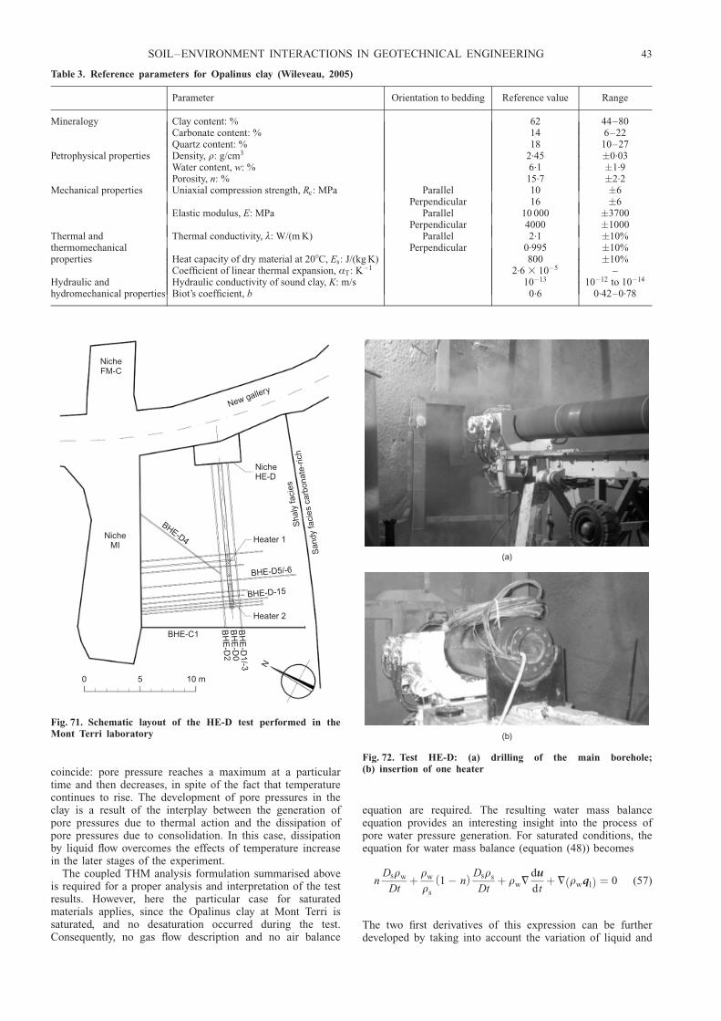
coincide: pore pressure reaches a maximum at a particulartime and then decreases, in spite of the fact that temperaturecontinues to rise. The development of pore pressures in theclay is a result of the interplay between the generation ofpore pressures due to thermal action and the dissipation ofpore pressures due to consolidation. In this case, dissipationby liquid flow overcomes the effects of temperature increasein the later stages of the experiment.
The coupled THM analysis formulation summarised aboveis required for a proper analysis and interpretation of the testresults. However, here the particular case for saturatedmaterials applies, since the Opalinus clay at Mont Terri issaturated, and no desaturation occurred during the test.Consequently, no gas flow description and no air balance
equation are required. The resulting water mass balanceequation provides an interesting insight into the process ofpore water pressure generation. For saturated conditions, theequation for water mass balance (equation (48)) becomes
nDsrw
Dtþ rw
rs
1 � nð Þ Dsrs
Dtþ rw=
du
dtþ = rwqlð Þ ¼ 0 (57)
The two first derivatives of this expression can be furtherdeveloped by taking into account the variation of liquid and
Table 3. Reference parameters for Opalinus clay (Wileveau, 2005)
Parameter Orientation to bedding Reference value Range
Mineralogy Clay content: % 62 44–80Carbonate content: % 14 6–22Quartz content: % 18 10–27
Petrophysical properties Density, r: g/cm3 2.45 �0.03Water content, w: % 6.1 �1.9Porosity, n: % 15.7 �2.2
Mechanical properties Uniaxial compression strength, Rc: MPa ParallelPerpendicular
1016
�6�6
Elastic modulus, E: MPa ParallelPerpendicular
10 0004000
�3700�1000
Thermal andthermomechanical
Thermal conductivity, º: W/(m K) ParallelPerpendicular
2.10.995
�10%�10%
properties Heat capacity of dry material at 208C, Es: J/(kg K) 800 �10%Coefficient of linear thermal expansion, ÆT: K�1 2.6 3 10�5 –
Hydraulic and Hydraulic conductivity of sound clay, K: m/s 10�13 10�12 to 10�14
hydromechanical properties Biot’s coefficient, b 0.6 0.42–0.78
NicheFM-C
NicheMI
BHE-D4
BHE-C1
0 5 10 m
N
BH
E-D
1/-3B
HE
-D0
BH
E-D
2
New gallery
NicheHE-D
Heater 1
BHE-D5/-6
BHE-D-15
Heater 2
San
dyfa
cies
carb
onat
e-ric
hS
haly
faci
es
Fig. 71. Schematic layout of the HE-D test performed in theMont Terri laboratory
(a)
(b)
Fig. 72. Test HE-D: (a) drilling of the main borehole;(b) insertion of one heater
SOIL–ENVIRONMENT INTERACTIONS IN GEOTECHNICAL ENGINEERING 43

solid densities, which with some simplifications are assumedto be given by
rw ¼ rw0 exp �w pl � pl0ð Þ þ bw T � Trefð Þ� �
(58)
rs ¼ rs0 exp �s pl � pl0ð Þ þ 3bs T � Trefð Þ� �
(59)
where �w and �s are the water and solid compressibilitiesrespectively, and bw and bs are the volumetric and linearthermal expansion coefficients for water and the solid phaserespectively. Expanding the first two derivatives of equation(57) results in
nbw þ 1 � nð Þ3bs½ � DsT
Dtþ n�w
Ds pl
Dt
þ 1 � nð Þ�s
Ds pl
Dtþ =
du
dtþ= rwqlð Þ
rw
¼ 0
(60)
Equation (60) contains most THM couplings that explain thegeneration and dissipation of pore pressure when a tempera-ture change is applied to the clay. The first term expressesthe differential thermal expansion of solid and liquid phases.The second and third terms are the volume changes of waterand solid phase water associated with a pore pressurechange; the fourth term is the volume change of the materialskeleton (includes contributions from stresses, pore pressuresand temperature); and the fifth term is the volume changeassociated with the flow of water in or out of the elementconsidered. The pore pressure generated and its evolutionare the result of the interplay of all these phenomena at eachparticular point.
A three-dimensional coupled THM analysis was per-formed so that the anisotropy of the material (thermalconductivity and stiffness) and of the in situ stress systemcould be accounted for. Because of the special character-istics of the Opalinus clay, a constitutive model has beenused that tries to account for the fact that the microstructureof the material is a combination of a clay matrix andcementing bonds. The constitutive law, which is described inVaunat & Gens (2003a, 2003b), is illustrated in Fig. 74. Asin Gens & Nova (1993), bonding results in an increase ofthe size of the yield surface, but in this case the degradationof the bonds is described by a specific damage model. Inthis way, matrix and bond behaviour as well as bond damagecan be described in an integrated manner. Extension tounsaturated conditions is described in Garitte et al. (2006).
A full description of the numerical modelling of the insitu test is presented in Gens et al. (2007); only someselected results are discussed here. Fig. 75 shows that the
evolution of temperature during the two heating stages iswell described by the three-dimensional analysis performed:a modest anisotropy in the temperature contours is discerned,owing to the different values of thermal conductivity parallelto and across the bedding planes. The computations alsocapture satisfactorily the variation of pore pressure resultingfrom thermal effects and dissipation (Fig. 76). The analysisrevealed that, as the test progressed, the location of themaximum pore pressures gradually moved away from theheater. The measured distribution of dilatant strains close tothe heaters and compressive strains away from the heaterswas also adequately reproduced by the analysis (Gens et al.,2007).
The mechanical constitutive model adopted provides in-formation on the likely damage experienced by the materialas a result of the thermal, hydraulic and mechanical actions.The consequences of damage are a degradation of elasticparameters and an increase in permeability. Fig. 77(a) showsthe computed distribution of the unloading elastic modulusat various test times: the predicted size of the damaged zoneincreases during the heating stage, but does not developfurther on cooling. During dismantling of the in situ test aborehole was drilled from the MI niche, perpendicular to themain borehole. The unconfined Young’s moduli of a seriesof samples taken from this borehole at different distancesfrom the heaters were determined by wave velocity measure-
4·0
3·5
3·0
2·5
2·0
1·5
Por
e pr
essu
re: M
Pa
Temperature - B03Pore pressure - B03
50
40
30
20
10
0
Tem
pera
ture
: °C
Date
12/03/0402/04/04
23/04/0414/05/04
04/06/0425/06/04
16/07/0406/08/04
27/08/0417/09/04
08/10/04
Fig. 73. Test HE-D: evolution of temperature and pore pres-sures measured in borehole D03
V V VS M b� �
Bond(volume )Vb
Void(volume )VV
Soil matrix(volume )VM
qbq
pt
0Bond damage
Unbonded
p *0
1M
K0line
Bonded
p
pbp *c0
(a)
(b)
Fig. 74. (a) Conceptual scheme for the constitutive model forOpalinus clay; (b) yield surfaces for bonded and unbondedmaterial and bond damage bubble (qb and pb are the stresses onthe bonds) (Vaunat & Gens, 2003a, 2003b)
44 GENS
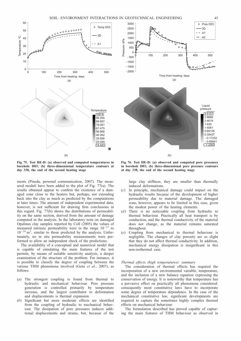
ments (Pineda, personal communication, 2007). The meas-ured moduli have been added to the plot of Fig. 77(a). Theresults obtained appear to confirm the existence of a dam-aged zone close to the heaters but, perhaps, not extendingback into the clay as much as predicted by the computationsat later times. The amount of independent experimental data,however, is not sufficient for drawing firm conclusions inthis regard. Fig. 77(b) shows the distributions of permeabil-ity on the same section, derived from the amount of damagecomputed in the analysis. In the laboratory tests on damagedOpalinus clay samples reported by Coll (2005) the values ofmeasured intrinsic permeability were in the range 10�17 to10�19 m2, similar to those predicted by the analysis. Unfor-tunately, no in situ permeability measurements were per-formed to allow an independent check of the predictions.
The availability of a conceptual and numerical model thatis capable of simulating the main features of the testpermits, by means of suitable sensitivity analysis, a deeperexamination of the structure of the problem. For instance, itis possible to classify the degree of coupling between thevarious THM phenomena involved (Gens et al., 2007), asfollows.
(a) The strongest coupling is found from thermal tohydraulic and mechanical behaviour. Pore pressuregeneration is controlled primarily by temperatureincrease, and the largest contributor to deformationand displacements is thermal expansion.
(b) Significant but more moderate effects are identifiedfrom the coupling of hydraulic to mechanical behav-iour. The dissipation of pore pressures induces addi-tional displacements and strains, but, because of the
large clay stiffness, they are smaller than thermallyinduced deformations.
(c) In principle, mechanical damage could impact on thehydraulic results because of the development of higherpermeability due to material damage. The damagedzone, however, appears to be limited in this case, giventhe modest power of the heating elements.
(d ) There is no noticeable coupling from hydraulic tothermal behaviour. Practically all heat transport is byconduction, and the thermal conductivity of the materialdoes not change, as the material remains saturatedthroughout.
(e) Coupling from mechanical to thermal behaviour isnegligible. The changes of clay porosity are so slightthat they do not affect thermal conductivity. In addition,mechanical energy dissipation is insignificant in thisnon-isothermal case.
Thermal effects (high temperatures): summaryThe consideration of thermal effects has required the
incorporation of a new environmental variable, temperature,and the inclusion of a new balance equation expressing theconservation of energy. It is noteworthy that temperature hasa pervasive effect on practically all phenomena considered:consequently most constitutive laws have to incorporatesome degree of temperature dependence. In the case of themechanical constitutive law, significant developments arerequired to capture the sometimes highly complex thermaleffects on mechanical behaviour.
The formulation described has proved capable of captur-ing the main features of THM behaviour as observed in
0
10
20
30
40
50
60
0
Time from heating: days
(a)
Tem
pera
ture
: ºC
Temp D03
3D
A1
500400300200100
(b)
Temperature
109·999·29488·68778·08167·47556·86846·26235·65625·04914·443
Fig. 75. Test HE-D: (a) observed and computed temperatures inborehole D03; (b) three-dimensional temperature contours atday 338, the end of the second heating stage
�2000
�1500
�1000
�500
0
500
1000
1500
2000
2500
3000
0
Time from heating: days(a)
Pre
ssur
e: k
Pa
Pres D03
3D
A1
A2
500400300200100
(b)
Liquidpressure
3·51572·98882·46191·9351·40810·881260·35437�0·17252�0·69941
�1·2263
Fig. 76. Test HE-D: (a) observed and computed pore pressuresin borehole D03; (b) three-dimensional pore pressure contoursat day 338, the end of the second heating stage
SOIL–ENVIRONMENT INTERACTIONS IN GEOTECHNICAL ENGINEERING 45

large-scale heating tests related to nuclear waste disposal.Satisfactory reproduction of behaviour has been achieved forboth unsaturated and saturated problems addressing quitedifferent phenomena. In the unsaturated case, evaporation,condensation, vapour migration and hydration are dominant.In the saturated case, the key issues are thermally inducedpore pressure generation, pore pressure dissipation, and claydamage. An enhanced understanding of the overall reposi-tory system is undoubtedly one of the main benefits of theavailability of a proper formulation, and of modelling toolscapable of incorporating the main physical phenomena aswell as their interactions.
THERMAL EFFECTS: LOW TEMPERATURESGeneral
This section deals with non-isothermal problems at lowtemperature, focusing on the study of frozen ground andfreezing–thawing phenomena. Freezing and frozen groundhas been a subject of permanent interest, especially but notexclusively for geotechnical engineers working in cold cli-mates (e.g. Andersland & Ladanyi, 2004). For instance,foundation of freezing facilities and the use of groundfreezing as a construction technique are problems that occurindependently of climate conditions, and still require a goodunderstanding of the physical processes involved. The sameunderstanding can be used to achieve a better comprehensionof glacial and periglacial processes, and their impact onpresent geomorphological features. Although the formulationto be described is general, the main application area isrelated to permafrost and freezing ground in cold regions.Permafrost underlies about 24% of the Northern hemispherelandmass, although of course most of those areas are thinly
inhabited. However, resource and transport development inremote areas requires the performance of major engineeringworks in permafrost areas. As an example, in the recentlyconstructed Qinhai-Tibet railway, of the total 1142 kmlength, 550 km are constructed on continuous permafrostand about 82 km more on discontinuous permafrost (Wu etal., 2006). There is also concern about potential permafrostdegradation due to possible climate changes (IPCC, 2007).Indeed, much of the material presented here is one resultfrom a multidisciplinary project funded by BP to address theissue of climate change risk assessment in cold regions(Clarke et al., 2008).
The process of soil freezing exhibits a certain degree ofcomplexity. Assuming that the soil is saturated, when thetemperature drops to 08C, the water least bound to the solidsurface starts to freeze. As the temperature drops further,more liquid water becomes frozen in a progressive manner.Liquid water/ice interfaces appear, which play a role similarto that of the liquid/gas interfaces in unsaturated soils (Fig.78). A consequence of this ongoing process is that liquidwater develops increasing values of suction as temperaturereduces: this suction is responsible for attracting water fromthe unfrozen soil areas, in response to the difference inpotential. Clearly, many of these concepts and phenomenarecall analogous concepts and phenomena discussed earlierin the context of unsaturated soils.
An early paper by Williams (1964) examined, usingcalorimetric techniques, the evolution of the unfrozen watercontent with temperature for a range of soils (Fig. 79). Therelationship between suction and water content for theunfrozen soils in an unsaturated condition was also estab-lished using a pressure plate apparatus. Thereby, the correla-tion between temperature and suction could be plotted forthe various soils. As Fig. 80 shows, a practically uniquerelationship is obtained.
This direct relationship between suction and temperaturecan in fact be expected from thermodynamic equilibriumconsiderations. If it is assumed that the two phases are inequilibrium, ice and liquid water have the same chemicalpotential, although they may have different pressures (e.g.Kirillin et al., 1976). Thus
� sl � sið ÞdT þ vld pl � vid pi ¼ 0 (61)
where sl, vl and pl are the specific entropy, the specificvolume and the pressure of liquid water respectively, and si,vi and pi are the same properties referred to ice. Rearran-
0
2
4
6
8
10
12
0
Distance to BH0: m(a)
Unl
oadi
ng m
odul
us: G
Pa
0 days (1)
90 days (2)
110 days (3)
338 days (4)
E measurements
1 2
3 4
642
1·00 10� �18
1·00 10� �19
1·00 10� �20
1·00 10� �170
Distance to BH0: m
Intr
insi
c pe
rmea
bilit
y: m
2
0 days (1)
90 days (2)
110 days (3)
338 days (4)
54321
(b)
Fig. 77. Test HE-D: (a) distribution of computed unloadingelastic modulus at various times on a section perpendicular tothe heater (values of elastic modulus obtained from samplestaken at the end of the test are plotted); (b) distribution ofcomputed permeability values at various times on a sectionperpendicular to the heater
Soil
Liquid
Ice
Inter-particlecontact force
Unfrozen water film
σli (Surface tension)
Piσli
Pl
Fig. 78. Schematic arrangement of solid phase, unfrozen water,ice and interfaces in a frozen soil
46 GENS
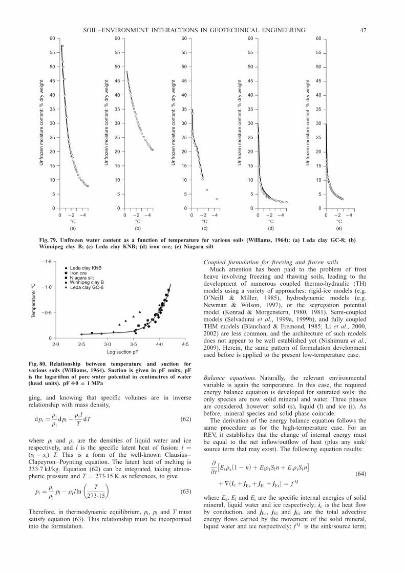
ging, and knowing that specific volumes are in inverserelationship with mass density,
d pi ¼ri
rl
d pl �ri l
TdT (62)
where rl and ri are the densities of liquid water and icerespectively, and l is the specific latent heat of fusion: l ¼(sl � si) T. This is a form of the well-known Clausius–Clapeyron–Poynting equation. The latent heat of melting is333.7 kJ/kg. Equation (62) can be integrated, taking atmos-pheric pressure and T ¼ 273.15 K as references, to give
pi ¼ri
rl
pl � ri l lnT
273:15
� �(63)
Therefore, in thermodynamic equilibrium, pi, pl and T mustsatisfy equation (63). This relationship must be incorporatedinto the formulation.
Coupled formulation for freezing and frozen soilsMuch attention has been paid to the problem of frost
heave involving freezing and thawing soils, leading to thedevelopment of numerous coupled thermo-hydraulic (TH)models using a variety of approaches: rigid-ice models (e.g.O’Neill & Miller, 1985), hydrodynamic models (e.g.Newman & Wilson, 1997), or the segregation potentialmodel (Konrad & Morgenstern, 1980, 1981). Semi-coupledmodels (Selvadurai et al., 1999a, 1999b), and fully coupledTHM models (Blanchard & Fremond, 1985; Li et al., 2000,2002) are less common, and the architecture of such modelsdoes not appear to be well established yet (Nishimura et al.,2009). Herein, the same pattern of formulation developmentused before is applied to the present low-temperature case.
Balance equations. Naturally, the relevant environmentalvariable is again the temperature. In this case, the requiredenergy balance equation is developed for saturated soils: theonly species are now solid mineral and water. Three phasesare considered, however: solid (s), liquid (l) and ice (i). Asbefore, mineral species and solid phase coincide.
The derivation of the energy balance equation follows thesame procedure as for the high-temperature case. For anREV, it establishes that the change of internal energy mustbe equal to the net inflow/outflow of heat (plus any sink/source term that may exist). The following equation results:
@
@ tEsrs 1 � nð Þ þ ElrlSl n þ EiriSi n� �þ = ic þ jEs þ jEl þ jEið Þ ¼ f Q
(64)
where Es, El and Ei are the specific internal energies of solidmineral, liquid water and ice respectively; ic is the heat flowby conduction, and jEs, jEl and jEi are the total advectiveenergy flows carried by the movement of the solid mineral,liquid water and ice respectively; f Q is the sink/source term;
60
55
50
45
40
35
30
25
20
15
10
5
0
Unf
roze
n m
oist
ure
cont
ent:
% d
ry w
eigh
t
0 �2 �4°C(a)
60
55
50
45
40
35
30
25
20
15
10
5
0
Unf
roze
n m
oist
ure
cont
ent:
% d
ry w
eigh
t
0 �2 �4°C(b)
60
55
50
45
40
35
30
25
20
15
10
5
0
Unf
roze
n m
oist
ure
cont
ent:
% d
ry w
eigh
t
0 �2 �4°C(c)
60
55
50
45
40
35
30
25
20
15
10
5
0
Unf
roze
n m
oist
ure
cont
ent:
% d
ry w
eigh
t
0 �2 �4°C(d)
60
55
50
45
40
35
30
25
20
15
10
5
0
Unf
roze
n m
oist
ure
cont
ent:
% d
ry w
eigh
t
0 �2 �4°C(e)
Fig. 79. Unfrozen water content as a function of temperature for various soils (Williams, 1964): (a) Leda clay GC-8; (b)Winnipeg clay B; (c) Leda clay KNB; (d) iron ore; (e) Niagara silt
�1·5
�1·0
�0·5
02·0 2·5 3·0 3·5 4·0 4·5
Log suction pF
Tem
pera
ture
: °C
Leda clay KNBIron oreNiagara siltWinnipeg clay BLeda clay GC-8
Fig. 80. Relationship between temperature and suction forvarious soils (Williams, 1964). Suction is given in pF units; pFis the logarithm of pore water potential in centimetres of water(head units). pF 4.0 1 MPa
SOIL–ENVIRONMENT INTERACTIONS IN GEOTECHNICAL ENGINEERING 47

and Sl and Si are the liquid and ice degrees of saturation,Sl + Si ¼ 1.
The specific internal energies are defined as
Es ¼ csT ; El ¼ clT ; Ei ¼ �l þ ciT (65)
where cs, cl and ci are the specific heats for solid mineral,liquid water and ice respectively. The specific heat of ice(2.05 kJ/(kg K) at 08C) is significantly lower than that ofliquid water (4.18 kJ/(kg K) at 258C).
To complete the formulation, the energy balance equationmust be solved together with the rest of the balance equa-tions: solid mass balance (equation (17)), water mass balance,
@
@ tŁw
l Sl n þ Łwi Si n
� �þ = jwl þ jwi
� �¼ f w (66)
and equilibrium (equation (18)). In equation (66) the reduc-tion of density when liquid water turns into ice must beconsidered. After phase change, the density of ice is916.2 kg/m3, and it increases only slowly as the temperaturereduces (e.g. 918.9 kg/m3 at �108C and 925.7 kg/m3 at�1008C). In the formulation it is assumed that there is noflow of ice relative to the solid phase ( jwi ¼ js), a realistichypothesis.
Constitutive equations. Only the most characteristic consti-tutive equations are briefly reviewed here. Again, the mostimportant mechanism for energy transport is heat conduction,governed by Fourier’s law (equation (52)). In this case thegeometric mean of the thermal conductivities of the phases,weighted by volumetric fractions, appears also to provide anadequate estimate of the overall thermal conductivity (Cote &Konrad, 2005):
º ¼ º1�ns ºSl n
l º 1�Slð Þn
i (67)
The thermal conductivity of liquid water (0.6 W/(m K) at258C) is significantly lower than that of ice (2.22 W/(m K) at08C).
As before, the advective flow of liquid, ql, is governed byDarcy’s law (equations (19) and (20)). As for unsaturatedsoils, relative permeability varies by several orders of magni-tude, depending on the degree of saturation of unfrozenwater content (Fig. 81). As soon as the ice content in thesoil grows, the flow of liquid water reduces drastically.
There is a clear parallel between the retention curve ofunsaturated soils and the freezing characteristic function thatrelates the degree of liquid (unfrozen water) saturation Sl tosoil suction (e.g. Black & Tice, 1989). Both of them aredetermined by the soil pore size characteristics and theinterface surface tension (Fredlund & Xing, 1994; Coussy,2005). Because of the requirement that the Clausius–Cla-peyron–Poynting equation (63) be satisfied, a well-estab-lished effect of temperature on the freezing characteristiccurve results.
The mechanical behaviour of frozen soils is undoubtedlycomplex. It has frequently been modelled using approachesbased on total stresses (e.g. Ladanyi, 1972; Nixon, 1978;Jessberger, 1981; He et al., 2000; Arenson & Springman,2005). Effective stress approaches using a single stressvariable have been less common. Li et al. (2000) adoptedBishop’s expression for effective stress, replacing gas pres-sure by ice pressure. This approach has the drawback that,in ice-rich soils in which ice pressure is dominant, it leadsto very low values of shear strength at low stresses, againstobservations.
Nishimura et al. (2009) have proposed a different mech-anical constitutive law based on the BBM, and using twoindependent stress variables: net stress, � ¼ �t � piI; and
suction, s ¼ pi � pl (Fig. 82). Here ice pressure pi plays therole of reference pressure. As shown in Fig. 82, the expan-sion of the yield surface when temperature reduces (asso-ciated with an increase of suction) involves both enhancedparticle interlocking (expansion towards the right) and icestrengthening (expansion towards the left). In this simpleway, the combined effects of porosity and ice strengtheningare accounted for. Fig. 83 compares qualitatively the strengthprediction of the model with experimental results obtainedin tests on frozen Ottawa sand (Goughnour & Andersland,1968). The model appears to accommodate the variousfactors contributing to the frozen soil strength. More infor-mation on the mechanical constitutive model is provided inNishimura et al. (2009).
Naturally, this very simple model fails to incorporatesome important features of behaviour: the most obvious oneis the characteristic time-dependent behaviour of frozenground. Also, the model does not account for the phenomen-on of cumulative thaw consolidation (Nixon & Morgenstern,1973). To reproduce these behaviour features it is necessaryto enhance the model to include a viscous formulation andcyclic behaviour inside the main yield locus, in a waysimilar to the generalisation of classical critical state models.
Development of ground freezingIt is interesting to test the formulation against current
understanding of the development of ground freezing. If thetemperature in the atmosphere drops below 08C for anextended period of time, ground freezing will develop fromthe surface downwards (Fig. 84). The boundary betweenfrozen and unfrozen soil will be in the region of the ground
10�7
10�8
10�9
10�10
10�11
10�12
10�13
Hyd
raul
ic c
ondu
ctiv
ity: m
/s
4–8 m fractionµ
Manchester
Chena
Calgary
Kaolinite
Illite
0 0·2 0·4 0·6
Unfrozen water content: m /m3 3
Fig. 81. Variation of hydraulic conductivity with unfrozen watercontent for various soils (Horiguchi & Miller, 1983)
48 GENS

where the temperature hovers around 08C, where a frozenfringe may develop. Liquid water is attracted to this regionbecause of the suction developing in the soil due to freezing.When liquid water reaches the frozen fringe it freezes,leading to an accumulation of ice in the area. High suctionsalso exist in the frozen ground above, but there is practicallyno flow of liquid water because of the extreme reductionof permeability with increasing ice content. Fig. 85 showsthe results of a one-dimensional analysis performed with theformulation outlined above. It has been assumed that thetemperature at the surface drops to –88C. The long-termdistributions of liquid saturation, porosity, ice and liquidpressures and temperature are presented. A frozen fringe hasdeveloped at a depth between 2 m and 3 m, characterised bya rapid drop in liquid saturation and a large increase ofporosity caused by ice accumulation. The development of asizeable frozen fringe requires that the boundary betweenfrozen and unfrozen ground remain approximately stationaryfor a significant period of time.
The evolution of porosity predicted by the model duringfreezing and subsequent thawing can be followed in Fig. 86.As freezing starts, net pressure reduces (because of in-creased ice pressure), and it may reach very low values (A–B). Accordingly, stiffness is very low, and the soil allows alarge increase in porosity to accommodate ice accumulation(B–C). If at some point temperature rises again, net stresswill increase again, owing to the reduction of ice pressure.The state of the soil will eventually travel down the virginconsolidation line until the initial stress condition is reached(C–D–F). A possible outcome is that, after the freezing–thawing cycle, the final soil porosity will be higher than the
initial one. If thawing is fast, pore water pressures maydevelop, ˜pl, that will finally dissipate to reach the samefinal equilibrium condition (C–D–E–F).
The study of both active and relic periglacial solifluctionhas been intense, because of the implications for slopestability in the areas where they are present (e.g. Hutchinson,1970; Chandler, 1976; Chandler et al., 1976; Skempton &
s
T T� 1
T T� 2
pn0
qCSL
Coolingbelow Tf
p0
(a)
s
pn0
qCSL
Coolingbelow Tf
p0
(b)
q
CSL
s
(c)
p
Unfrozenstate:ModifiedCam-Clay
Fig. 82. Mechanical constitutive model for frozen soils(Nishimura et al., 2009): (a) projections of the yield surface,ice-rich soil; (b) projections of the yield surface, ice-poor soil;(c) three-dimensional view of the yield surface for frozen soils
4
3
2
1
0
Pea
k st
reng
th,
: M
Pa
q
0 0·2 0·4 0·6
Volume fraction of soil particles(a)
Ice strength
Ice strengthening
0 50 100
Dr: %
Soil strength Dilatancy�
Soil strength Structural hindrance�
4
3
2
1
0
qa
t crit
ical
sta
te: M
Pa
0 0·2 0·4 0·6
Volume fraction of soil particles(b)
Ice strength: 0·46 (273·15 )M Mk T� �ks2
q Mcs �p ksn0
2�
Fig. 83. Shear strength against porosity relationships: (a) experi-mental results from unconfined compression tests on Ottawasand at 278C and strain rate of 4.4 3 1024 s21 (after Goughnour& Andersland, 1968); (b) prediction of the constitutive model ofNishimura et al. (2009)
Ice
Soil particle
Liquid water
Liquid waterflow
Frozen fringe
Fig. 84. Ground freezing phenomena with the development ofan ice-rich frozen fringe
SOIL–ENVIRONMENT INTERACTIONS IN GEOTECHNICAL ENGINEERING 49
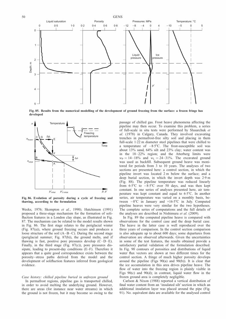
Weeks, 1976; Skempton et al., 1990). Hutchinson (1991)proposed a three-stage mechanism for the formation of soli-fluction features in a London clay slope, as illustrated in Fig.87. The mechanism can be related to the model results shownin Fig. 86. The first stage relates to the periglacial winter(Fig. 87(a)), where ground freezing occurs and produces aloose structure of the soil (A–B–C). During the second stage(periglacial summer; Fig. 87(b)), the ground melts, and ifthawing is fast, positive pore pressures develop (C–D–E).Finally, in the third stage (Fig. 87(c)), pore pressures dis-sipate, leading to present-day conditions (E–F). Therefore itappears that a quite good correspondence exists between theporosity–stress paths derived from the model and thedevelopment of solifluction features inferred from geologicalevidence.
Case history: chilled pipeline buried in unfrozen groundIn permafrost regions, pipeline gas is transported chilled,
in order to avoid melting the underlying ground. However,there are areas (for instance near water streams) in whichthe ground is not frozen, but it may become so owing to the
passage of chilled gas. Frost heave phenomena affecting thepipeline may then occur. To examine this problem, a seriesof full-scale in situ tests were performed by Slusarchuk etal. (1978) in Calgary, Canada. They involved excavatingtrenches in permafrost-free silty soil and placing in themfull-scale 1.22 m diameter steel pipelines that were chilled toa temperature of �8.58C. The frost-susceptible soil wasabout 13% sand, 64% silt and 23% clay; water content wasin the 18–22% region; and the Atterberg limits werewP ¼ 14–18% and wL ¼ 24–31%. The excavated groundwas used as backfill. Subsequent ground heave was moni-tored for periods from 3 to 10 years. The analyses of twosections are presented here: a control section, in which thepipeline invert was located 2 m below the surface; and adeep burial section, in which the invert depth was 2.9 m(Fig. 88). The pipeline temperature was reduced linearlyfrom 6.58C to �8.58C over 50 days, and was then keptconstant. In one series of analyses presented here, air tem-perature was kept constant and equal to 6.58C. In anotherseries, air temperature was varied on a monthly basis, be-tween �88C in January and +16.58C in July. Computedpipeline heaves were very similar for the two hypotheses.The complete series of computations and the full details ofthe analyses are described in Nishimura et al. (2009).
In Fig. 89 the computed pipeline heave is compared withobservations for the control case and the deep burial case.The heave in the latter case is well reproduced over thethree years of comparison. In the control section comparisonis also adequate up to about 600 days; some departures fromobservation are observed afterwards. Given the uncertaintiesin some of the test features, the results obtained provide asatisfactory partial validation of the formulation described.In Fig. 90 contours of porosities and distributions of liquidwater flux vectors are shown at two different times for thecontrol section. A fringe of much higher porosity developsaround the pipeline (Figs 90(a) and 90(b)). It is clear thatthe ice accumulation in this area drives pipeline heave. Theflow of water into the freezing region is plainly visible inFigs 90(c) and 90(d); in contrast, liquid water flow in thefrozen ground area is completely negligible.
Carlson & Nixon (1988) reported a vertical distribution offinal water content from an ‘insulated silt’ section in which anadditional insulation layer was placed around the pipe (Fig.91). No. equivalent data are available for the analysed control
0
1
2
3
4
5
Dep
th: m
Liquid saturation
0 0·5 1·0 0·2 0·4 0·6 0·8
Porosity
�12 �8 �4 0 4
Pressures: MPa
�10 �5 0 5
Temperature: °C
p�
Icepressure
Liquidpressure
Fig. 85. Results from the numerical modelling of the development of ground freezing from the surface: a frozen fringe hasdeveloped
n
nfrozen
ninitial
C DE
∆pl
Temperature
Freezingtemperature
Time
F
B ∆n
A
p p, �p �initial p �0 initial
Fig. 86. Evolution of porosity during a cycle of freezing andthawing, according to the formulation
50 GENS
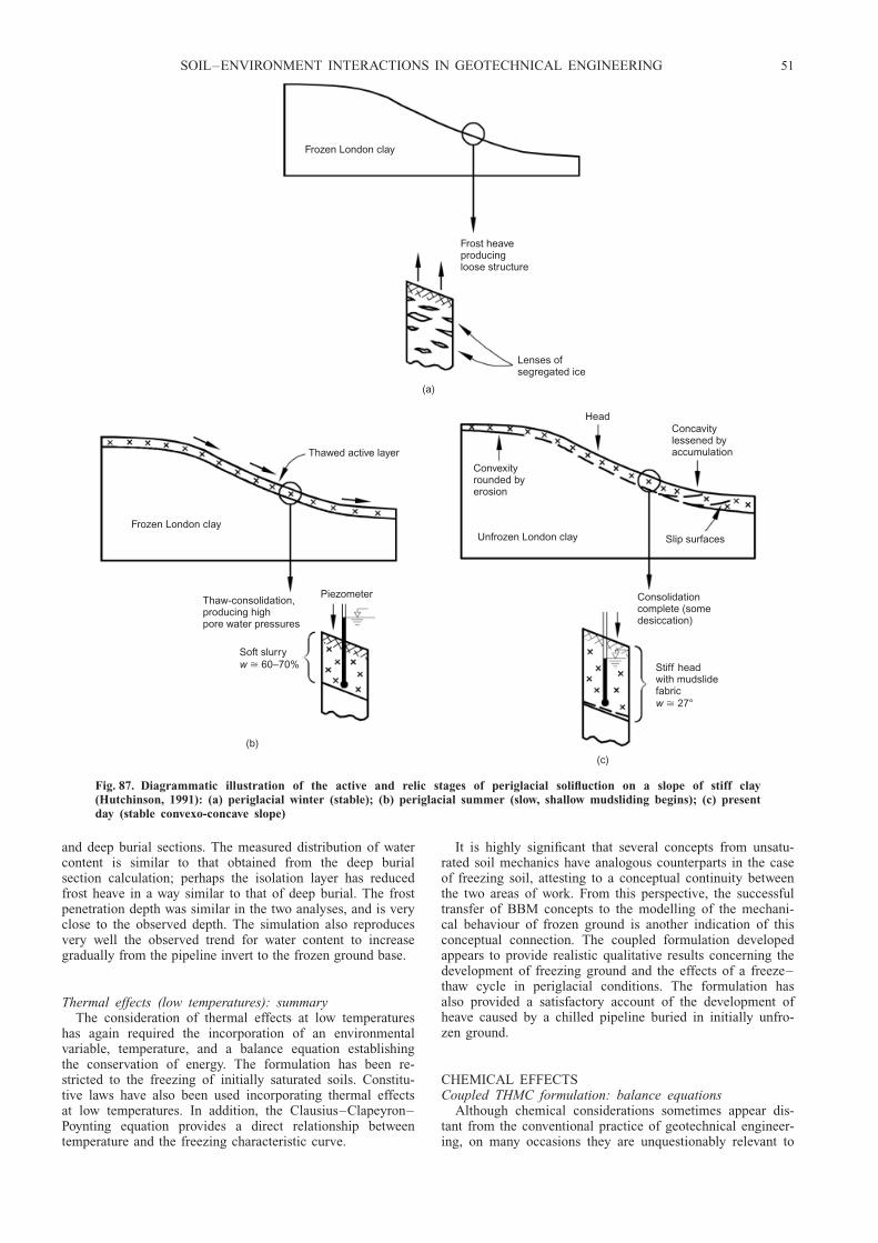
and deep burial sections. The measured distribution of watercontent is similar to that obtained from the deep burialsection calculation; perhaps the isolation layer has reducedfrost heave in a way similar to that of deep burial. The frostpenetration depth was similar in the two analyses, and is veryclose to the observed depth. The simulation also reproducesvery well the observed trend for water content to increasegradually from the pipeline invert to the frozen ground base.
Thermal effects (low temperatures): summaryThe consideration of thermal effects at low temperatures
has again required the incorporation of an environmentalvariable, temperature, and a balance equation establishingthe conservation of energy. The formulation has been re-stricted to the freezing of initially saturated soils. Constitu-tive laws have also been used incorporating thermal effectsat low temperatures. In addition, the Clausius–Clapeyron–Poynting equation provides a direct relationship betweentemperature and the freezing characteristic curve.
It is highly significant that several concepts from unsatu-rated soil mechanics have analogous counterparts in the caseof freezing soil, attesting to a conceptual continuity betweenthe two areas of work. From this perspective, the successfultransfer of BBM concepts to the modelling of the mechani-cal behaviour of frozen ground is another indication of thisconceptual connection. The coupled formulation developedappears to provide realistic qualitative results concerning thedevelopment of freezing ground and the effects of a freeze–thaw cycle in periglacial conditions. The formulation hasalso provided a satisfactory account of the development ofheave caused by a chilled pipeline buried in initially unfro-zen ground.
CHEMICAL EFFECTSCoupled THMC formulation: balance equations
Although chemical considerations sometimes appear dis-tant from the conventional practice of geotechnical engineer-ing, on many occasions they are unquestionably relevant to
Frozen London clay
Frost heaveproducingloose structure
Lenses ofsegregated ice
Frozen London clay
(a)
Head
Thawed active layer
Concavitylessened byaccumulation
Slip surfaces
Convexityrounded byerosion
Unfrozen London clay
PiezometerThaw-consolidation,producing highpore water pressures
Soft slurry60–70%w �
(b)
Consolidationcomplete (somedesiccation)
Stiff headwith mudslidefabric
27°w �
(c)
Fig. 87. Diagrammatic illustration of the active and relic stages of periglacial solifluction on a slope of stiff clay(Hutchinson, 1991): (a) periglacial winter (stable); (b) periglacial summer (slow, shallow mudsliding begins); (c) presentday (stable convexo-concave slope)
SOIL–ENVIRONMENT INTERACTIONS IN GEOTECHNICAL ENGINEERING 51

engineering problems. Without being comprehensive, thefollowing chemical processes can be mentioned as poten-tially relevant: precipitation/dissolution phenomena (e.g. con-cerning carbonates or sulphates), cation exchange, oxidation/reduction processes (e.g. involving pyrites or iron com-pounds), breaking down of silicate minerals, and sulphatereduction (Mitchell & Soga, 2005). These processes have asignificant influence on the hydraulic and mechanical proper-ties of soils and other geotechnical materials by way ofcementation, degradation, volume change, porosity varia-tions, modification of pore structure, change in swellingproperties of clays and others. Chemical interactions alsounderlie important phenomena such as weathering, sulphate-induced swelling in tunnels, methane hydrate dissociation or
biodegradation (Kimoto et al., 2007; McDougall, 2007).Moreover, they are directly related to processes such asosmotic flow, which may be significant in some clay-richmaterials (Barbour & Fredlund, 1989; Manassero & Dom-ijiani, 2003; Peters & Smith, 2004), and they are critical inareas such as contaminant transport and soil decontamina-tion.
It seems appropriate, therefore, to generalise further theformulation developed hitherto in order to incorporate arange of relevant chemical phenomena (Gens et al., 2002b,2005). Additional chemical species, which may react witheach other, must now be incorporated. Consequently, thesolid phase now includes not only the main mineral but alsoprecipitated minerals and absorbed cations, and the coinci-dence of solid phase and mineral species no longer applies.The liquid phase contains water, dissolved air and, in addi-tion, dissolved chemical species. At present, no chemicalspecies are considered in the gas phase, but they could beeasily included if required. Chemical reactions considered inthe formulation include
(a) homogeneous reactions involving only the liquid phase:aqueous complex formation, acid–base reactions, oxi-dation/reduction reactions
(b) heterogeneous reactions involving the liquid and solidphases: dissolution/precipitation of minerals and cationexchange.
Local equilibrium is assumed for all the chemical reac-tions except for some dissolution/precipitation of minerals,where kinetics may also be assumed. The use of one orother of these two hypotheses depends on the comparisonbetween rates (or characteristic times) of concentrationchanges due either to chemical reactions or to transport(Steefel & Lasaga, 1994). Local equilibrium is the limitingcase for kinetics when transport characteristic times aremuch higher than those of the chemical reactions as it isgenerally the case in porous materials, especially if they arefine-grained.
As before, new variables and new balance equations mustbe added to the formulation. The new variables are theconcentrations ci of each one of the additional chemicalspecies, and the new balance equations are the reactivetransport equations that express the conservation of mass ofthose chemical species. Assuming N chemical species, thebalance equations are expressed as
@
@ tnSlrlcið Þ þ =j i ¼ Ri (i ¼ 1, . . ., N ) (68)
where ci is the concentration of species i, in mol/kg ofsolution, and Ri is the total production rate of species i dueto chemical reactions, in mol/(m3/s). In this case the right-hand side term is very important, because it expresses theeffect of the chemical reactions that occur throughout theporous medium. ji is the total flux of species i, expressed inmol/(m2/s). It is convenient to express the total flux ji as
j i ¼ j9i þ nSlrlci _u (69)
where _u is the solid phase velocity and j9i is the flux ofspecies i with respect to the solid phase. j9i is given by thesum of the liquid advective flux and the non-advective flux,
j i ¼ rlciql � D l=ci (70)
where ql is the Darcy’s liquid flux and D l is the hydro-dynamic dispersion tensor. The non-advective flux is theconsequence of both molecular diffusion and mechanicaldispersion.
It is now necessary to introduce the reactions in localequilibrium to obtain the set of independent concentrationsin the system. If Nx is the number of reversible independent
Berm andbackfill
1·22 m pipe
Trenchexcavatedin soil
(a)
0·46 m
2 m
Trenchexcavated1 m deeperthan control
(b)
2·9 m
Fig. 88. Sections of a full-scale in situ pipeline frost heave test(after Slusarchuk et al., 1978): (a) control section; (b) deepburial section
80
60
40
20
0
Hea
ve o
fpi
pelin
e: c
m
0 200 400 600 800 1000
Time: days
Observed
Simulated
DD
C
CMonthly varying air temperature
Constant air temperature
Berm constructed
Fig. 89. Computed and observed pipeline heave: C, controlsection; D, deep burial section (Nishimura et al., 2009)
52 GENS

reactions in a system containing N species, then the numberof independent chemical components is Nc ¼ N � Nx. Reac-tions between the two types of species are expressed as
Ai ¼XNc
j¼1
�ij A j i ¼ 1, . . ., Nxð Þ (71)
where A j and Ai are the chemical formulae of the primaryand secondary species respectively, and �ij is the number ofmoles of the primary species j in a mole of the secondaryspecies i. The classification of the species into primary andsecondary ones is not unique, but it is decided on the basisof the characteristics of the problem being analysed.
Only the equations of the primary variables enter the setof balance equations to be solved; the concentrations of thesecondary variables are derived from the chemical equili-brium model outlined below. This allows the total number ofdegrees of freedom of the analyses to be reduced. Even withthis reduction, the number of primary chemical species canbe quite large in some cases. For instance, in the analysis ofthe coupled thermo-hydromechanical and chemical (THMC)behaviour of a bentonite sample subjected to heating andhydration, a total of 28 chemical species were considered,10 of which were primary species (Gens et al., 2008a). Inmany applications, however, less comprehensive chemical
0·40·50·6
0·70·4
0·4
0·4
0·5
0·6
0·5
0·35 0·80·7 0·6
(a)
(c) (d)
0·40·50·4
0·4
0·4
0·40·5
0·5
(b)
Fig. 90. Analysis of control section with monthly varying temperature (Nishimura et al., 2009). Deformed geometry andporosity contours: (a) at day 300; (b) at day 1000. Liquid water flux vectors: (c) at day 300; d) at day 1000
0 20 40 60 80 100 120
Water content: %
0
1
2
3
4
5
Dep
th b
elow
pip
elin
e ba
se: m
Observed baseof frozen soil
Simulated (deep burial)
Simulated (control)
Observed (insulated)
Fig. 91. Computed and observed water content distributionsbeneath the pipeline. Observations provided by Carlson andNixon (1988) for the ‘insulated silt’ section
SOIL–ENVIRONMENT INTERACTIONS IN GEOTECHNICAL ENGINEERING 53

models and fewer primary variables are required. A moredetailed description of the THMC formulation has beenpresented in Guimaraes (2002) and Guimaraes et al. (1999,2007). The formulation has been incorporated into a compu-ter code, CODE_BRIGHT, capable of performing fullycoupled THMC analyses (Guimaraes et al., 2006). Othergeneral THMC schemes have been presented by Thomas etal. (2001), Seetharam et al. (2007) and Zheng & Samper(2008).
Coupled THMC formulation: constitutive equationsChemical equilibrium and kinetics. Most reactive transportformulations use the mass action law to solve the chemicalequilibrium equations (e. g. Steefel & Lasaga, 1994; Saaltinket al., 1998). In the formulation presented here, an alternative(but thermodynamically equivalent) approach is used, basedon the minimisation of Gibbs free energy. This approach hasa wider application range, extending to non-ideal veryconcentrated systems. To compute the concentrations of thespecies in equilibrium, a Newton–Raphson algorithm isapplied to the direct minimisation of Gibbs free energy.Lagrange multipliers are used to incorporate the restrictionsof the problem (Harvie et al., 1987).
The minimisation problem can thus be written as
minimizenc
j,nx
i
G ¼XNc
j¼1
�cj nc
j þXNx
i¼1
�xi nx
i (72)
subject to:
nUj ¼ nc
j þXNx
i¼1
�ij nxi j ¼ 1, . . ., Ncð Þ
ncj > 0 j ¼ 1, . . ., Ncð Þ
nxi > 0 i ¼ 1, . . ., Nxð Þ
(73)
where G is the Gibbs free energy, and �cj and �x
i are thechemical potentials of the primary and secondary species. nc
j
and nxi , the variables to be optimised, are the number of
moles of the primary and secondary species in an REV. Thenumber of moles nc
j and nxi are directly related to concentra-
tions. For the few chemical reactions that can be consideredkinetics-controlled, the rate of species production is com-puted using a standard formulation (e.g. Fletcher, 1993).
Chemo-mechanical models. There are many chemical pro-cesses that affect the mechanical behaviour of soils. Becauseof this wide spectrum of phenomena, the tendency has beentowards the development of chemo-mechanical modelsaddressing the effects of an individual process or a limitedset of phenomena, such as organic contaminant effects onclays (Hueckel, 1997), water-ion interaction in expansiveclays (Gajo et al., 2002; Loret et al., 2002), pressure solution/precipitation in salt (Olivella & Gens, 2002) and in chalk(Pietruszczak et al., 2006), ion exchange in swelling clays(Gens et al., 2002b), chemical degradation of bondedgeomaterials (Nova et al., 2003), and degradation of softclayey rocks (Pinyol et al., 2007). Zhang & Zhou (2008) havepresented a chemo-plastic model for unsaturated soils thatcombines the chemo-mechanical model of Hueckel (1997)with the unsaturated model of Gallipoli et al. (2003). Inprinciple, the structure of a chemo-mechanical model wouldbe
d�� ¼ D �, s, T , cð Þ d�ð Þ þ h �, s, T , cð Þds
þ � �, s, T , cð ÞdT þ ˆ �, s, T , cð Þdc(74)
where a new term has been added that represents the mech-anical contribution of the set of chemical species concentra-tions, ci, grouped in the vector c. Frequently, concentrationsare not incorporated directly in the constitutive laws, butother chemically derived parameters are used instead. Forinstance, Nova et al. (2003) assumed that the variouschemical state variables can be condensed into a singlescalar function incorporating the effects of processes such astime of exposure to weathering or chemical attack intensity.Hueckel (1992) used the accumulated mass transfer ofadsorbed water as constitutive parameter.
An example of a chemo-mechanical model is brieflysketched here. It deals with the effect of cation exchange inexpansive clays such as bentonite, a phenomenon that isrelevant to engineered barriers for nuclear waste disposal.Changes in cation content in these materials bring aboutsignificant mechanical effects, which may affect volumechange characteristics and swelling pressure potential (DiMaio, 1996). An instance of bentonite behaviour that re-quires modelling is illustrated in Fig. 92, which shows thecompression experienced by a sample of saturated bentonitewhen exposed to saturated solutions of different electrolytes.This behaviour is often attributed to changes in osmoticsuction: in this case the osmotic suction applied is 185 MPafor the CaCl2 solution, 39 MPa for the NaCl solution, and24 MPa for the KCl solution. It is apparent that the relation-ship between osmotic suction and volumetric strain is notstraightforward: the effect of the CaCl2 solution is not muchhigher than those of the other electrolytes, and the volu-metric strains for NaCl and KCl solutions are in factreversed with respect to their values of osmotic suction. It isclear that the nature of the particular cation also plays a rolein the observed mechanical behaviour of the bentonite.
The chemo-mechanical model is built upon the general-ised-plasticity double-structure model used in the THMmodelling of the mock-up test presented above (Sanchez etal., 2005). It will be recalled that the model distinguishesbetween a macrostructural level and a microstructural level.As the microstructure is the seat of the physico-chemicalinteractions occurring in the vicinity of clay particles, themicrostructural level provides a very convenient platform forintroducing chemical effects. The relationship with the over-all mechanical behaviour of the soil is then handled by thegeneral configuration of the model. The chemical constitu-tive parameters selected for formulating the model are the
0
10
20
30
ε v: %
100 101 102 103 104 105
Time: min
KClCaCl2
Exposure to saturatedNaCl solution
Consolidation underpressure increment from320 kPa to 640 kPa
Fig. 92. Volume changes of Ponza bentonite subjected to theaction of different solutions in an oedometer (after Di Maio,1996)
54 GENS
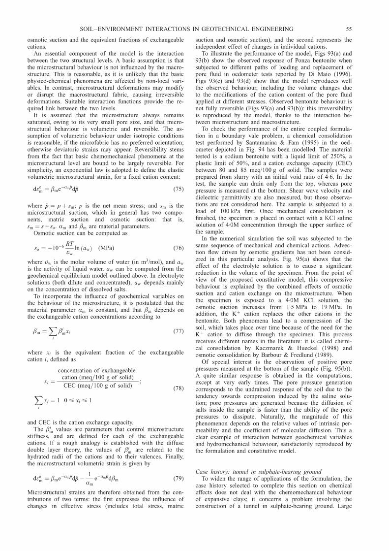
osmotic suction and the equivalent fractions of exchangeablecations.
An essential component of the model is the interactionbetween the two structural levels. A basic assumption is thatthe microstructural behaviour is not influenced by the macro-structure. This is reasonable, as it is unlikely that the basicphysico-chemical phenomena are affected by non-local vari-ables. In contrast, microstructural deformations may modifyor disrupt the macrostructural fabric, causing irreversibledeformations. Suitable interaction functions provide the re-quired link between the two levels.
It is assumed that the microstructure always remainssaturated, owing to its very small pore size, and that micro-structural behaviour is volumetric and reversible. The as-sumption of volumetric behaviour under isotropic conditionsis reasonable, if the microfabric has no preferred orientation;otherwise deviatoric strains may appear. Reversibility stemsfrom the fact that basic chemomechanical phenomena at themicrostructural level are bound to be largely reversible. Forsimplicity, an exponential law is adopted to define the elasticvolumetric microstructural strain, for a fixed cation content:
d�em ¼ �me�Æm ppdpp (75)
where pp ¼ p þ sm; p is the net mean stress; and sm is themicrostructural suction, which in general has two compo-nents, matric suction and osmotic suction: that is,sm ¼ s + so. Æm and �m are material parameters.
Osmotic suction can be computed as
so ¼ �10�6 RT
vw
ln awð Þ (MPa) (76)
where vw is the molar volume of water (in m3/mol), and aw
is the activity of liquid water. aw can be computed from thegeochemical equilibrium model outlined above. In electrolytesolutions (both dilute and concentrated), aw depends mainlyon the concentration of dissolved salts.
To incorporate the influence of geochemical variables onthe behaviour of the microstructure, it is postulated that thematerial parameter Æm is constant, and that �m depends onthe exchangeable cation concentrations according to
�m ¼X
i
�imxi (77)
where xi is the equivalent fraction of the exchangeablecation i, defined as
xi ¼concentration of exchangeable
cation (meq=100 g of solid)
CEC (meq=100 g of solid);
Xi
xi ¼ 1 0 < xi < 1
(78)
and CEC is the cation exchange capacity.The �i
m values are parameters that control microstructurestiffness, and are defined for each of the exchangeablecations. If a rough analogy is established with the diffusedouble layer theory, the values of �i
m are related to thehydrated radii of the cations and to their valences. Finally,the microstructural volumetric strain is given by
d�em ¼ �me�Æm ppdpp � 1
Æm
e�Æm ppd�m (79)
Microstructural strains are therefore obtained from the con-tributions of two terms: the first expresses the influence ofchanges in effective stress (includes total stress, matric
suction and osmotic suction), and the second represents theindependent effect of changes in individual cations.
To illustrate the performance of the model, Figs 93(a) and93(b) show the observed response of Ponza bentonite whensubjected to different paths of loading and replacement ofpore fluid in oedometer tests reported by Di Maio (1996).Figs 93(c) and 93(d) show that the model reproduces wellthe observed behaviour, including the volume changes dueto the modifications of the cation content of the pore fluidapplied at different stresses. Observed bentonite behaviour isnot fully reversible (Figs 93(a) and 93(b)): this irreversibilityis reproduced by the model, thanks to the interaction be-tween microstructure and macrostructure.
To check the performance of the entire coupled formula-tion in a boundary vale problem, a chemical consolidationtest performed by Santamarina & Fam (1995) in the oed-ometer depicted in Fig. 94 has been modelled. The materialtested is a sodium bentonite with a liquid limit of 250%, aplastic limit of 50%, and a cation exchange capacity (CEC)between 80 and 85 meq/100 g of solid. The samples wereprepared from slurry with an initial void ratio of 4.6. In thetest, the sample can drain only from the top, whereas porepressure is measured at the bottom. Shear wave velocity anddielectric permittivity are also measured, but those observa-tions are not considered here. The sample is subjected to aload of 100 kPa first. Once mechanical consolidation isfinished, the specimen is placed in contact with a KCl salinesolution of 4.0M concentration through the upper surface ofthe sample.
In the numerical simulation the soil was subjected to thesame sequence of mechanical and chemical actions. Advec-tion flow driven by osmotic gradients has not been consid-ered in this particular analysis. Fig. 95(a) shows that theeffect of the electrolyte solution is to cause a significantreduction in the volume of the specimen. From the point ofview of the proposed constitutive model, this compressivebehaviour is explained by the combined effects of osmoticsuction and cation exchange on the microstructure. Whenthe specimen is exposed to a 4.0M KCl solution, theosmotic suction increases from 1.5 MPa to 19 MPa. Inaddition, the Kþ cation replaces the other cations in thebentonite. Both phenomena lead to a compression of thesoil, which takes place over time because of the need for theKþ cation to diffuse through the specimen. This processreceives different names in the literature: it is called chemi-cal consolidation by Kaczmarek & Hueckel (1998) andosmotic consolidation by Barbour & Fredlund (1989).
Of special interest is the observation of positive porepressures measured at the bottom of the sample (Fig. 95(b)).A quite similar response is obtained in the computations,except at very early times. The pore pressure generationcorresponds to the undrained response of the soil due to thetendency towards compression induced by the saline solu-tion; pore pressures are generated because the diffusion ofsalts inside the sample is faster than the ability of the porepressures to dissipate. Naturally, the magnitude of thisphenomenon depends on the relative values of intrinsic per-meability and the coefficient of molecular diffusion. This aclear example of interaction between geochemical variablesand hydromechanical behaviour, satisfactorily reproduced bythe formulation and constitutive model.
Case history: tunnel in sulphate-bearing groundTo widen the range of applications of the formulation, the
case history selected to complete this section on chemicaleffects does not deal with the chemomechanical behaviourof expansive clays; it concerns a problem involving theconstruction of a tunnel in sulphate-bearing ground. Large
SOIL–ENVIRONMENT INTERACTIONS IN GEOTECHNICAL ENGINEERING 55

floor heave displacements and large swelling pressures havebeen observed in numerous tunnelling works performed inrocks containing anhydrites, and quite often have requiredmajor repairs. North-west Switzerland and South Germany
are areas especially affected; tunnelling in this type ofmaterial is considered a major engineering problem (Kovariet al., 1988; Wittke & Wittke, 2005; Berdugo et al., 2009a,2009b). Despite over 100 years of tunnelling in such ground,
8
7
6
5
4
3
2
1
0
Voi
d ra
tio, e
0·01 0·10 1·0 10·0
σv: MPa
(a)
Water
NaCl
Replacement ofcell fluid
NaClWater
8
7
6
5
4
3
2
1
0
Voi
d ra
tio, e
0·01 0·10 1·0 10·0
σv: MPa
(b)
Replacement ofcell fluid
NaCl
Water
8
7
6
5
4
3
2
1
0
Voi
d ra
tio, e
0·01 0·10 1·0 10·0p: MPa
(c)
Water
Replacement ofcell fluid
NaClWater
8
7
6
5
4
3
2
1
0
Voi
d ra
tio, e
0·01 0·10 1·0 10·0
p: MPa(d)
Replacement ofcell fluid
NaCl
Water
Water
Fig. 93. (a, b) Volume changes of Ponza bentonite subjected to combined chemo-mechanical actions in an oedometer (afterDi Maio, 1996); (c, d) computed volume changes using the chemo-mechanical model for Ponza bentonite subjected tocombined chemo-mechanical actions
Load
Solution
3
3
21Powersupply
MultimeterPC Analyser
Pulse generator
Amplifier
Oscilloscope
Fig. 94. Schematic layout of the oedometer test (Santamarina & Fam, 1995)
56 GENS

the basic phenomena involved are still not well understood(Anagnostou, 2007). The long duration of the swellingphenomena and the great variability of field conditions areserious obstacles to a systematic study of the problem.However, some advances in the understanding of the phe-nomena have been made recently, in connection with thecase described below (Alonso et al., 2005, 2007; Berdugo,2007; Berdugo et al., 2007a).
The case concerns the construction of three tunnels, partof a section of the new high-speed train line from Madrid toBarcelona, in the lower Tertiary Ebro Basin (northeastSpain), an area where other heave phenomena have alreadybeen reported (Gens et al., 1993). All three tunnels hadsimilar problems; only the case history of the longest one,the 2034 m-long Lilla tunnel, is discussed here. A fulldescription of the case history, including the informationgiven below, is presented in Berdugo (2007). The 117.3 m2
horseshoe section was excavated by drill and blast from thetwo portals, dividing the section into advance and bench(Fig. 96(a)). Overburden along the tunnel varies between10 m and 110 m. Temporal supports consisted of sprayedconcrete and rock bolts; steel arch ribs (HEB 160) wereinstalled only in zones of low-quality rock. Lining consistedof 300 mm-thick mass concrete (25 MPa). A 300 mm-thickflat slab constructed in mass concrete was placed on thetunnel floor, but it was concreted only after the total excava-tion of the bench. Therefore the floor of the tunnel wasexposed to the action of environmental agents during mostof the construction period. Because of the low permeabilityof the massif, waterproofing of the excavated section wasrestricted to portals.
The tunnel runs mainly through Early Eocenic argilla-ceous deposits containing anhydrite and a very complexsystem of cross-shaped, moderately dipping, fibrous gypsumveins (Fig. 97). The veins are from millimetric to centimetricin thickness; gypsum is also present as small nodules andflakes. The host argillaceous matrix is constituted of illite
and paligorskite, of minerals rich in magnesium and calcium(dolomite) and, to a lesser extent, of quartz. Expansive clayminerals were detected only in small quantities, in isolatedpoints of the matrix. An important aspect is the existence ofa persistent system of open, low-friction-angle, slickensidedsurfaces related to local tectonics.
First heave manifestations were detected in the flat slabjust after the full tunnel excavation was completed. Substan-tial expansive phenomena occurred in a generalised way atfloor level, but movements were only slight in the unlinedvault. Heave was followed by damage to the longitudinaldrainage system and, finally, by local failures of flat slabs.As usual in this type of problem, the magnitude of heavewas extremely variable, resulting in a very irregular tunnelfloor surface. It is thought likely that the variability of heaveis related to local permeability variations, connected perhapsto the presence of fissures or fractures. Fig. 98 shows thedistribution of heave displacements along the tunnel duringthe first six months of observations, as well as the depth ofthe active zone in the areas where it was measured.
Figure 99(a) illustrates the evolution of heave in a numberof sections. The movements are quite large, and do not showany indication of a decreasing rate of growth with time.
100
10
1
0·1
0·01
Ver
tical
str
ain:
%
0 2000 4000 6000 8000 10000Time: min
(a)
Test
0 2000 4000 6000 8000
Time: min(b)
0·05
0·04
0·03
0·02
0·01
0
Por
e pr
essu
re: M
Pa
Fig. 95. Observed and computed results from a sodium bento-nite oedometer sample exposed to a 4.0M solution of KCl: (a)vertical deformation; (b) pore pressure measured at the bottomof the specimen. Experimental results from Santamarina & Fam(1995)
�
�
Sprayed concrete(300 mm)
Cast-in-placeconcrete 25 MPa
(300 mm)
Flat slabmass concrete
20 MPa (300 mm)
5%
5%
Invert40 MPa
(400 600 mm)�
(a)
(b)
5%
Sprayedconcrete(300 mm)
Cast-in-placeconcrete 25 MPa
(300 mm)R
6·46
m
�
R
6·46
m
�
5%
Fig. 96. Lilla tunnel: (a) generic cross-section; (b) cross-sectionwith inverted arch
SOIL–ENVIRONMENT INTERACTIONS IN GEOTECHNICAL ENGINEERING 57

Sliding micrometers placed in some sections showed thatmovements were concentrated in the first 3–4 m under thetunnel slab (Fig. 100).
After the ground heave was observed, the section of thetunnel between chainages 411 + 556 and 411 + 860 wasprovided with an invert arch, of which 184 m had a thick-ness of 400 mm and 110 m had a thickness of 600 mm.Instrumentation was also installed, including total pressurecells on the underside of the invert and sliding micrometersto measure displacements under the floor. Fig. 99(b) showsthe swelling stresses that were measured on the invert arch:very large stresses, of the order of several MPa, typical ofthis type of phenomenon, were recorded. In spite of therestraint provided by the invert arch, heave displacements ofup to 27 mm were still measured, concentrated in the first4–5 m below the new floor.
Remedial measures for this type of problem veer betweenthe provision of a rigid support capable of resisting the verylarge swelling pressures, and the installation of a yieldingsupport that allows rock deformation without causing unduedamage to the floor. In this context, three test sections werebuilt in a zone where the tunnel had been excavated to a fullcircular shape (Berdugo et al., 2007b). The first section
(20 m long) was designed according to the principle ofresisting support. The other two (both 10 m long) weredesigned according to the principle of yielding support: oneincluded sliding slots in the contact between the vault andthe invert; in the second one, a polyurethane foam (approxi-mately 150 mm thick) was placed in the interface betweenrock and invert. An excavated circular section was adoptedto try to minimise overstressing of the rock and thereby limitdamage and fracturing. The circular test sections were ini-tially flooded under controlled conditions, using water fromthe rock massif. The direct access of water from the tunnelfloor to the rock was possible owing to a series of boreholesdrilled after building the circular sections. The floodingperiod was 30 days only.
Figure 101 shows clearly the dependence of swellingpressure on the stiffness of the support. Fig. 102 shows thedistributions of heave displacements with depth for theresisting support section and for the yielding support sectionwith slots. It is apparent that heave phenomena continue totake place below the newly excavated circular section. Themeasurements also suggest that the magnitude of the activezone is larger for the yielding support case; it appears thatallowing the development of displacements to minimise
400
300
m a
.s.l.
411 100� 412 000� 413 000�
North portal(Lleida) South portal
(Martorell)
Quaternary Middle Eocene
Limestone
Marl
Early Eocene
Claystone and siltstone
Gypsiferous-anhydriticclaystone
Fig. 97. Geological longitudinal section of the Lilla tunnel (Berdugo, 2007)
0
�10
�8
�6
�4
�2
Testsection
with invertsince
Jan 2003
�20
4
�23
8
�87
8
50
100
150
200
Hea
ve: m
mD
epth
: m
Active zone limit: Mar 03(sliding micrometers)
Fresh rock level: Oct 02(boreholes analysis)
Drainage:�1·40 m
Flat slab axis reference: 9/20/02Oct 02
Mar 03Left abutment
Slab Slabuntil Nov 2002
Slabuntil May 03Zone with lining
413 300�413 000�412 000�411 100�
�15
0
�55
6
�86
0
�50
0�
545
�59
3
Fig. 98. Distribution of heave displacements and depth of active zone along the Lilla tunnel (Berdugo, 2007)
58 GENS
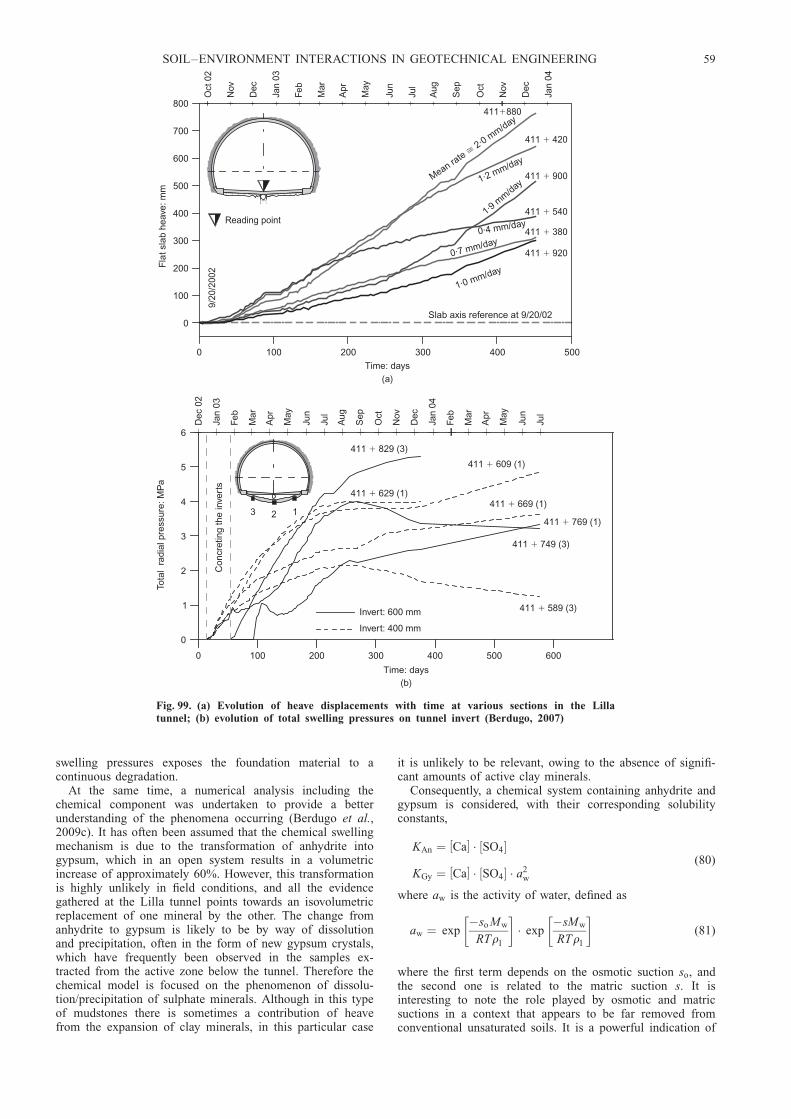
swelling pressures exposes the foundation material to acontinuous degradation.
At the same time, a numerical analysis including thechemical component was undertaken to provide a betterunderstanding of the phenomena occurring (Berdugo et al.,2009c). It has often been assumed that the chemical swellingmechanism is due to the transformation of anhydrite intogypsum, which in an open system results in a volumetricincrease of approximately 60%. However, this transformationis highly unlikely in field conditions, and all the evidencegathered at the Lilla tunnel points towards an isovolumetricreplacement of one mineral by the other. The change fromanhydrite to gypsum is likely to be by way of dissolutionand precipitation, often in the form of new gypsum crystals,which have frequently been observed in the samples ex-tracted from the active zone below the tunnel. Therefore thechemical model is focused on the phenomenon of dissolu-tion/precipitation of sulphate minerals. Although in this typeof mudstones there is sometimes a contribution of heavefrom the expansion of clay minerals, in this particular case
it is unlikely to be relevant, owing to the absence of signifi-cant amounts of active clay minerals.
Consequently, a chemical system containing anhydrite andgypsum is considered, with their corresponding solubilityconstants,
KAn ¼ Ca½ � � SO4½ �
KGy ¼ Ca½ � � SO4½ � � a2w
(80)
where aw is the activity of water, defined as
aw ¼ exp�so Mw
RTrl
� � exp
�sMw
RTrl
� (81)
where the first term depends on the osmotic suction so, andthe second one is related to the matric suction s. It isinteresting to note the role played by osmotic and matricsuctions in a context that appears to be far removed fromconventional unsaturated soils. It is a powerful indication of
500400300200100
1·0 mm/day
0·7 mm/day
1·9mm/day
1·2 mm/day
Mean rate2·0
mm/day
�
600500400300200100
0
Time: days(a)
0
100
200
300
400
500
600
700
800
Fla
t sla
b he
ave:
mm
411 380�
411 420�
411 540�
Slab axis reference at 9/20/02
411 880�
411 900�
411 920�
Oct
02
Nov
Dec
Jan
03
Feb
Mar
Apr
May
Jun
Jul
Aug
Sep
Oct
Nov
Dec
Jan
04
9/20
/200
2Reading point
0
Time: days
(b)
0
1
2
3
4
5
6
Tota
l ra
dial
pre
ssur
e: M
Pa
Dec
02
Jan
03
Feb
Mar
Apr
May
Jun
Jul
Aug
Sep
Oct
Nov
Dec
Jan
04
Feb
Mar
Apr
May
Jun
Jul
Con
cret
ing
the
inve
rts
13 2
Invert: 400 mm
Invert: 600 mm 411 589 (3)�
411 829 (3)�
411 609 (1)�
411 669 (1)�
411 749 (3)�
411 769 (1)�
411 629 (1)�
0·4 mm/day
Fig. 99. (a) Evolution of heave displacements with time at various sections in the Lillatunnel; (b) evolution of total swelling pressures on tunnel invert (Berdugo, 2007)
SOIL–ENVIRONMENT INTERACTIONS IN GEOTECHNICAL ENGINEERING 59

the basic consistency of the physical principles that underliethe progressive series of generalisations performed.
According to the chemical model, if the following in-equality holds, KAn , KGy=a2
w, anhydrite precipitates; if, onthe other hand, KGy=a2
w , KAn, then gypsum precipitates.The variation of porosity of the medium, n, is derived fromthe mass conservation of the inert mineral species, and it isaffected by chemical and mechanical phenomena accordingto
Dn
Dt¼ �n
1 þ M r
DM r
Dtþ 1 � n 1 þ M rð Þ
1 þ M r
= _u (82)
where the first term expresses the chemically induced poros-ity changes, and the second term contains the variation ofporosity due to volume change. Mr is the sum of reactiveminerals obtained from the geochemical model. Finally, inthis qualitative analysis, the volumetric deformation asso-ciated with precipitation/dissolution is simply assumed to belinearly related to the change of reactive mineral, accordingto
_�chv ¼ D�ch
v
Dt¼
n
1 � n 1 þ M rð ÞDM r
Dt(83)
where �chv is the chemically induced volumetric strain and
is a multiplier parameter. A rigorous approach to this issueis presented in Coussy (2006).
The analyses have considered two different cases: infiltra-tion of water into the rock (Fig. 103(a)) and evaporation of
water into the tunnel (Fig. 103(b)). One-dimensional ana-lyses have been performed, resulting in the evolutions ofheave plotted in Fig. 104 for the two mechanisms examined.The magnitude of heave computed in the analyses is notsignificant, since parameters have been adjusted to obtainrealistic values. However, it is interesting to observe thecalculated evolution of the heave over time. The analysespredict a slowing-down of heave for the case of water entryinto the rock, but a practically indefinite increase of heavefor the evaporation case, at least for the simulation timeused in the analysis. Performance of two-dimensional ana-lyses has yielded similar results. It should be pointed outthat, in the analysis, a homogenised medium has beenassumed. In reality, flow (and probably most crystallisation)takes place in fractures and discontinuities: here the effectsof those discontinuities are subsumed in the parameters ofthe overall medium. Also, no degradation of the clay matrixhas been considered. Some details of the results of theanalyses are shown in Fig. 105. The computations predictthat heave will be concentrated into the 3–4 m adjacent tothe tunnel, values similar to the observed ones (Figs 105(a)and 105(c)). The process driving the development of heaveis mineral precipitation, the distributions of which areplotted in Figs 105(b) and 105(d) for different times.
To take a decision on the engineering solution of theproblem and, in particular, whether to choose a resisting or ayielding support, a number of factors were taken intoaccount: (a) the fact that it was a single tunnel with noalternative (major repairs would probably close down thehigh-speed line); (b) the idea that preventing movements
R6·46 m
� R6·46 m
�
EIC3
Dec
200
3
Aug
200
3
Oct
200
3
EIC2 EIC1
Feb
2003
1
3
5
7
9
Feb
2003
1
3
5
7
9
EIC3
Dec
200
3
Dec
200
3
Dec
200
3
EIC2 EIC1
Mar
200
3
1
3
5
7
9
Mar
200
3
1
3
5
7
9M
ar 2
003
�8 �4 0 �8 �4 0 �8 �4 0
Extension: mm/m(b)
1
3
5
7
9
Feb
2003
�8 �4 0 �8 �4 0 �8 �4 0
Extension: mm/m(a)
1
3
5
7
9
Fig. 100. Distributions of heave displacements with depth in two sections with flat slab (Berdugo, 2007): (a) chainage412 + 150; (b) chainage 412 + 500
60 GENS
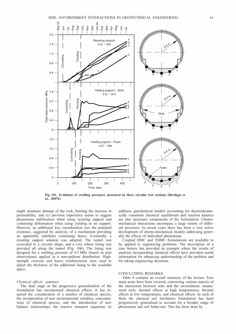
might minimise damage of the rock, limiting the increase inpermeability; and (c) previous experience seems to suggestphenomena stabilisation when using resisting support andcontinuing deformation when using yielding or no support.However, an additional key consideration was the potentialexistence, suggested by analysis, of a mechanism providingan apparently indefinite continuing heave. Eventually, aresisting support solution was adopted. The tunnel wasexcavated to a circular shape, and a very robust lining wasprovided all along the tunnel (Fig. 106). The lining wasdesigned for a swelling pressure of 4.5 MPa (based on pastobservations) applied in a non-uniform distribution. High-strength concrete and heavy reinforcement were used toadjust the thickness of the additional lining to the availablespace.
Chemical effects: summaryThe final stage in the progressive generalisation of the
formulation has incorporated chemical effects. It has re-quired the consideration of a number of chemical species,the incorporation of new environmental variables, concentra-tions of chemical species, and the introduction of newbalance relationships, the reactive transport equations. In
addition, geochemical models accounting for thermodynam-ically consistent chemical equilibrium and reaction kineticsare also necessary components of the formulation. Chemo-mechanical interactions encompass a large variety of differ-ent processes. In recent years there has been a very activedevelopment of chemo-mechanical models addressing gener-ally the effects of individual phenomena.
Coupled HMC and THMC formulations are available tobe applied to engineering problems. The description of acase history has provided an example where the results ofanalyses incorporating chemical effects have provided usefulinformation for enhancing understanding of the problem andfor taking engineering decisions.
CONCLUDING REMARKSTable 4 contains an overall summary of the lecture. Four
main areas have been covered, concerning various aspects ofthe interaction between soils and the environment: unsatu-rated soils; thermal effects at high temperatures; thermaleffects at low temperatures; and chemical effects. In each ofthem the classical soil mechanics formulation has beenprogressively generalised to account for a broader range ofphenomena and soil behaviour. This has been done by
May
03
Jun
Jul
Aug
Sep
Oct
Nov
Dec
Jan
04
Feb
Mar
Apr
May
Jun
Jul
0 100 200 300 400
Time: days
Tota
l rad
ial p
ress
ure:
MP
a
0
0·4
0·8
1·2
1·6
0
0·4
0·8
0·2
1·6
0·4
0·8
1·2
1·6
2·0
6·0m
6·0m
6·0m
1
234
5
1
234
5
Slots
Foam
1234
5
Yielding support – Foam412 590�
Con
cret
ing
Con
cret
ing
Con
cret
ing
Flo
odin
gF
lood
ing
Flo
odin
g
1
3
54
453
2
451
2
Yielding support – Slots412 574�
Resisting support412 552�
1
Fig. 101. Evolution of swelling pressures measured in three circular test sections (Berdugo etal., 2007b)
SOIL–ENVIRONMENT INTERACTIONS IN GEOTECHNICAL ENGINEERING 61

(a) introducing new basic variables: suction, temperature,concentration of chemical species
(b) adding or enhancing the balance equations as requiredby the formulation: water mass balance, air massbalance, energy balance, reactive transport equations(mass balance of the chemical species) and equilibrium(momentum balance). This has allowed the performanceof coupled analysis of increasing degree of complexity:TH, THM, THMC.
(c) extending constitutive laws to account for generalisedsoil behaviour. New developments have especially been
needed to describe the mechanical behaviour of soils, akey component of geotechnical engineering, and thefocus of intense research activity. Of necessity, only asmall number of mechanical constitutive laws havebeen briefly discussed in the lecture.
(d ) demonstrating the application of the theoretical for-mulations to case histories in order to illustrate therelevance and usefulness of the developments described.
The full set of balance equations is collected in Table 5, andthe evolving form of the constitutive laws as they progres-sively include additional phenomena is shown in Table 6.
It must be emphasised, however, that these developmentshave been made using the spirit and methods of classical
Extension: mm/m(a)
Extension: mm/m(b)
EIC2
EIC2
EIC1
EIC1
Jan
2004
Oct
200
3
Jan
2004
Jan
2004
Sep
200
3S
ep 2
003
Sep
200
3S
ep 2
003
�8
�8
�8
�8
�4
�4
�4
�4
0
0
0
0
9
9
9
9
7
7
7
7
5
5
5
5
3
3
3
3
1
1
Fig. 102. Distribution of relative displacements in circular testsections: (a) resisting support; (b) yielding support (slots)(Berdugo et al., 2007b)
Activezone
Gypsumgrowth
Stablezone
(a)
Activezone
Gypsumgrowth
Stablezone
(b)
Fig. 103. Mechanisms considered in the analyses: (a) waterinfiltration into the rock; (b) water evaporation into the tunnel
Evaporation
Water entry
Time: days0 400 800 1200
0
0·2
0·4
0·6
Hea
ve: c
m
Fig. 104. Computed heave evolution for the two mechanismsexamined
62 GENS
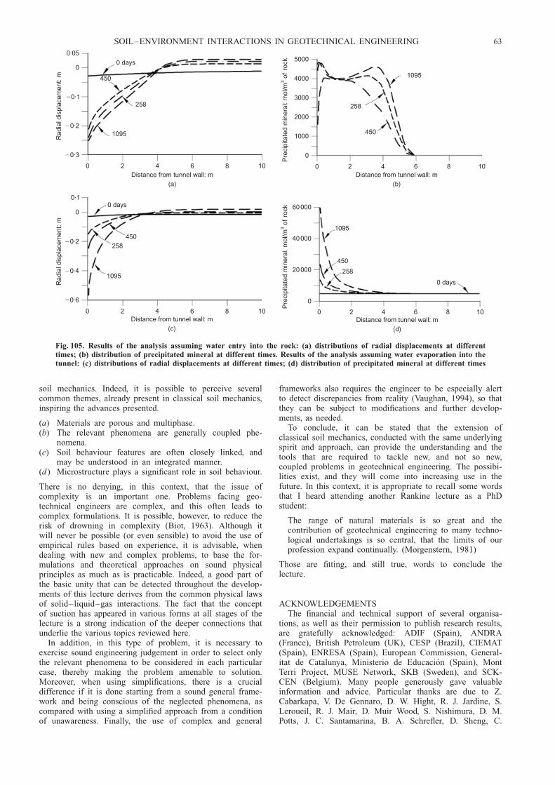
soil mechanics. Indeed, it is possible to perceive severalcommon themes, already present in classical soil mechanics,inspiring the advances presented.
(a) Materials are porous and multiphase.(b) The relevant phenomena are generally coupled phe-
nomena.(c) Soil behaviour features are often closely linked, and
may be understood in an integrated manner.(d ) Microstructure plays a significant role in soil behaviour.
There is no denying, in this context, that the issue ofcomplexity is an important one. Problems facing geo-technical engineers are complex, and this often leads tocomplex formulations. It is possible, however, to reduce therisk of drowning in complexity (Biot, 1963). Although itwill never be possible (or even sensible) to avoid the use ofempirical rules based on experience, it is advisable, whendealing with new and complex problems, to base the for-mulations and theoretical approaches on sound physicalprinciples as much as is practicable. Indeed, a good part ofthe basic unity that can be detected throughout the develop-ments of this lecture derives from the common physical lawsof solid–liquid–gas interactions. The fact that the conceptof suction has appeared in various forms at all stages of thelecture is a strong indication of the deeper connections thatunderlie the various topics reviewed here.
In addition, in this type of problem, it is necessary toexercise sound engineering judgement in order to select onlythe relevant phenomena to be considered in each particularcase, thereby making the problem amenable to solution.Moreover, when using simplifications, there is a crucialdifference if it is done starting from a sound general frame-work and being conscious of the neglected phenomena, ascompared with using a simplified approach from a conditionof unawareness. Finally, the use of complex and general
frameworks also requires the engineer to be especially alertto detect discrepancies from reality (Vaughan, 1994), so thatthey can be subject to modifications and further develop-ments, as needed.
To conclude, it can be stated that the extension ofclassical soil mechanics, conducted with the same underlyingspirit and approach, can provide the understanding and thetools that are required to tackle new, and not so new,coupled problems in geotechnical engineering. The possibi-lities exist, and they will come into increasing use in thefuture. In this context, it is appropriate to recall some wordsthat I heard attending another Rankine lecture as a PhDstudent:
The range of natural materials is so great and thecontribution of geotechnical engineering to many techno-logical undertakings is so central, that the limits of ourprofession expand continually. (Morgenstern, 1981)
Those are fitting, and still true, words to conclude thelecture.
ACKNOWLEDGEMENTSThe financial and technical support of several organisa-
tions, as well as their permission to publish research results,are gratefully acknowledged: ADIF (Spain), ANDRA(France), British Petroleum (UK), CESP (Brazil), CIEMAT(Spain), ENRESA (Spain), European Commission, General-itat de Catalunya, Ministerio de Educacion (Spain), MontTerri Project, MUSE Network, SKB (Sweden), and SCK-CEN (Belgium). Many people generously gave valuableinformation and advice. Particular thanks are due to Z.Cabarkapa, V. De Gennaro, D. W. Hight, R. J. Jardine, S.Leroueil, R. J. Mair, D. Muir Wood, S. Nishimura, D. M.Potts, J. C. Santamarina, B. A. Schrefler, D. Sheng, C.
0 days
450
258
1095
Distance from tunnel wall: m(a)
0 2 4 6 8 10
Rad
ial d
ispl
acem
ent:
m0·05
0
�0·1
�0·2
�0·3
0 days
450258
1095
Distance from tunnel wall: m(c)
0 2 4 6 8 10
Rad
ial d
ispl
acem
ent:
m
0·1
0
�0·2
�0·4
�0·6
Pre
cipi
tate
d m
iner
al: m
ol/m
ofro
ck3
1095
258
450
Distance from tunnel wall: m(b)
0 2 4 6 8 10
0
1000
2000
3000
4000
5000
Pre
cipi
tate
d m
iner
al: m
ol/m
ofro
ck3
Distance from tunnel wall: m(d)
1095
450
258
0 days
0 2 4 6 8 10
0
20000
40000
60000
Fig. 105. Results of the analysis assuming water entry into the rock: (a) distributions of radial displacements at differenttimes; (b) distribution of precipitated mineral at different times. Results of the analysis assuming water evaporation into thetunnel: (c) distributions of radial displacements at different times; (d) distribution of precipitated mineral at different times
SOIL–ENVIRONMENT INTERACTIONS IN GEOTECHNICAL ENGINEERING 63

Viggiani, O. Vilar, M. V. Villar, H.-S. Yu and L. Zdravkovic.David Hight, Dave Potts and Lidija Zdravkovic also providedinvaluable assistance in the final preparation of the lecture.
Most of the work presented has been done in collabora-tion with past and present members of the geotechnicalgroup at the Technical University of Catalonia (UPC): J.Alcoverro, M. Arroyo, I. Berdugo, A. Di Mariano, D.Gallipoli, L. do N. Guimaraes, B. Garitte, J. M. Gesto, N.Gonzalez, A. Josa, A. Ledesma, A. Lloret, S. Olivella, R. A.Rodrigues, E. Romero, M. Sanchez, J. Suriol, B. Vallejan, J.Vaunat and, of course, E. E. Alonso, who has been therefrom the beginning. I am very indebted to them for theirnumerous and important contributions.
Finally, special thanks go to my wife Dolors and mydaughters, Clara, Julia and Nuria, who have patiently en-dured the long preparation and writing of this lecture,providing support and encouragement at all times.
NOTATIONAi, A j chemical formulae of primary and secondary species
aw chemical activity of waterb vector of body forcesb Biot’s coefficient
bs linear thermal expansion coefficient of the solid phasebw volumetric thermal expansion coefficient of waterci concentration of chemical species i
R6·
46�
R
6·00
�1·30
(a)
(b)
Fig. 106. (a) Resisting support solution with a lining designed towithstand heave pressures; (b) construction of the new lining
Ta
ble
4.
Su
mm
ary
of
the
lect
ure
Var
iable
Bal
ance
equ
atio
ns
Co
up
led
anal
ysi
sC
on
stit
uti
ve
equ
atio
ns
Cas
eh
isto
ries
Wat
erA
irE
ner
gy
Rea
ctiv
etr
ansp
ort
Eq
uil
ib.
Sat
ura
ted
soil
sL
iqu
idp
ress
ure
,p
lY
esY
esH
MU
nsa
tura
ted
soil
sS
uct
ion
,s
Yes
Yes
Yes
HM
Bar
celo
na
Bas
icM
od
el(A
lon
soet
al.
,1
99
0)
Mic
rost
ruct
ure
-bas
edm
od
el(G
alli
po
liet
al.
,2
00
3)
Co
up
led
hy
dro
-mec
han
ical
mo
del
(Sh
eng
eta
l.,
20
04
)
Fo
un
dat
ion
coll
apse
inP
erei
raB
arre
to(B
razi
l)S
ub
sid
ence
inR
aven
na
(Ita
ly)
Th
erm
al,
hig
hte
mp
erat
ure
sT
emp
erat
ure
,T
Yes
Yes
Yes
TH
MD
ou
ble
stru
ctu
rem
od
el(S
anch
ezet
al.
,2
00
5)
Bo
nd
-mat
rix
elas
to-p
last
icm
od
el(V
aun
at&
Gen
s,2
00
3a)
Feb
exm
ock
-up
test
of
anen
gin
eere
db
arri
er,
Mad
rid
(Sp
ain
)In
situ
hea
tin
gte
stin
Op
alin
us
clay
,M
on
tT
erri
(Sw
itze
rlan
d)
Th
erm
al,
low
tem
per
atu
res
Tem
per
atu
re,
TY
esY
esY
esY
esT
HM
En
han
ced
BB
Mm
od
el(N
ish
imu
raet
al.
,2
00
9).
Ch
ille
dp
ipel
ine
bu
ried
inu
nfr
oze
ng
rou
nd,
Cal
gar
y(C
anad
a)C
hem
ical
Co
nce
ntr
atio
n,
cY
esY
esY
esY
esY
esT
HM
CC
hem
o-p
last
icm
od
elfo
rca
tio
nex
chan
ge
Tu
nn
elin
sulp
hat
e-b
eari
ng
rock
,L
illa
(Sp
ain
)
HM
,hy
dro
-mec
han
ical
;T
HM
,th
erm
o-h
yd
ro-m
ech
anic
al;
TH
MC
,th
erm
o-h
yd
ro-m
ech
anic
al-c
hem
ical
.
64 GENS

cp,m, cv,m specific heat capacity at constant pressure and atconstant volume, in molar terms
ciÆ specific heat capacity of species i in phase Æ phase
(i ¼ w, a; Æ ¼ l, g)D matrix describing the relationship between increments
of strains and constitutive stressesD9 matrix describing the relationship between increments
of strains and effective stressesD9g mechanical dispersion tensor
Dwg vapour diffusion coefficient in Fick’s law
Dwm molecular diffusion coefficient of vapour in open air
Ds(.)/Dt material derivative with respect to the solidEi specific internal energy of iceEÆ specific internal energy of phase Æ (Æ ¼ s, l, g)
e void ratioes void ratio in saturated virgin consolidation linef i external supply of species i (i ¼ w, a)
f Q external supply of energyf (s) mean interparticle force
G Gibbs free energyg gravity vectorg gravitational accelerationh vector that relates changes of constitutive stresses to
changes in suctionh thickness of film of adsorbed waterI identity matrix
IP plasticity indexic conductive heat flux
iiÆ non-advective mass flux (i ¼ w, a; Æ ¼ l, g)
jEÆ advective energy flux in phase Æ with respect to a fixedreference system (Æ ¼ s, l, g)
jw total mass flux of water with respect to a fixed referencesystem
jiw total mass flux of ice with respect to a fixed referencesystem
j iÆ total mass flux of species i in phase Æ with respect to a
fixed reference system (i ¼ w, a; Æ ¼ l, g)j9iÆ total mass flux of species i in phase Æ with respect to
the solid phase (i ¼ w, a; Æ ¼ l, g)K Æ permeability tensor (Æ ¼ l, g)
K bulk modulus of soilKl bulk modulus of liquid phase
Km equilibrium constant for mineral–water reaction (m ¼An, Gy)
Ks bulk modulus of solid phasek intrinsic permeability tensork permeabilityl latent heat
M slope of critical state lineMr total reactive minerals
Mw molecular mass of waterm inverse of bulk modulus
Nc number of independent chemical componentsNx number of reversible independent chemical reactions
n porositynm number of moles
nc, nx number of moles of primary and secondary speciesp mean net stress
p9 mean effective stress in saturated soils; mean Bishop’sstress in unsaturated soils
pp microstructural effective stress (¼ p + sm)pa air pressurepc reference stress in the BBMpi ice pressureps left intercept of yield surface in the BBMpt mean total stresspv vapour pressure
p0v vapour pressure at zero suction
pw water pressure; pore water pressurep0 net mean yield stress at current suction
p�0 net mean yield stress for saturated conditions
p10 limit value of p0 for infinite suction
pÆ pressure of phase Æ (Æ ¼ l, g)qw volumetric flux of water with respect to the solidqÆ volumetric flux of phase Æ with respect to the solid
(Æ ¼ l, g)q triaxial deviatoric stressR universal gas constant
Rc uniaxial compression strengthRi rate of production of chemical species i
RH relative humidityr parameter in the BBM
Sg gas degree of saturationSi ice degree of saturationSl (liquid) degree of saturations matric suction
si, sl specific entropy of ice (i) and liquid water (l)sm microstructural suctionso osmotic suctionst total suctionT absolute temperaturet timeu solid displacement vector
ua air pressureuw water pressureV volume
Table 5. Balance equations
Mass balance of solid@
@ t[Łs(1 � n)] þ = � js ¼ 0
Mass balance of water@
@ t(Łw
l Sl n þ Łwg Sg n) þ = � ( jwl þ jwg ) ¼ f w
Mass balance of air@
@ t(Ła
l Sl n þ ŁagSg n) þ = � ( jal þ jag) ¼ f a
Energy balance@
@ t[Esrs(1 � n) þ ElrlSl n þ EgrgSg n] þ = � (ic þ jEs þ jEl þ jEg) ¼ f Q
Reactive transport equation (mass balance of chemical species)@
@ t(nSlrlci) þ = � j i ¼ Ri (i ¼ 1, . . ., N )
Momentum balance (equilibrium) = � �t þ b ¼ 0
Table 6. Structure of constitutive laws
Hydro-mechanical (HM) law: saturated soils d�9 ¼ D9(�)(d�)Hydro-mechanical (HM) law: unsaturated soils d�� ¼ D(�, s)(d�) þ h(�, s)dsThermo-hydro-mechanical law (THM) d�� ¼ D(�, s, T )(d�) þ h(�, s, T )ds þ �(�, s, T )dTThermo-hydro-mechanical-chemical law (THMC) d�� ¼ D(�, s, T , c)(d�) þ h(�, s, T , c)ds þ �(�, s, T , c)dT þ ˆ(�, s, T , c)dc
SOIL–ENVIRONMENT INTERACTIONS IN GEOTECHNICAL ENGINEERING 65

vi , vl specific volume of ice (i) and liquid water (l)vw molar volume of waterWp plastic work
w water contentwL, wP liquid limit, plastic limit
Xi concentration of secondary chemical species ixi equivalent fraction of exchangeable cation i
x, y space coordinatesz vertical space coordinate
Æm material parameter in chemo-mechanical modelÆT coefficient of linear thermal expansion of the medium� vector that relates stresses and temperature changes� parameter in the BBM
�m material parameter in the chemo-mechanical model�w, �s water and solid compressibilities
ˆ matrix describing the relationship between incrementsof chemical concentrations and constitutive stresses
ªw unit weight of water� strain tensor
�m microstructural strain�v volumetric strain�ch
v chemically induced volumetric strain�p
v plastic volumetric strain�w volumetric water content (¼ nSl)�ª triaxial deviatoric strain� parameter defining the flow rule in the model by Sheng
et al. (2004) parameter in chemo-mechanical modelŁs density of solid phaseŁw
t density of ice
ŁiÆ (¼ rÆø
iÆ ) mass of species i in phase Æ per unit volume
of phase Æ (i ¼ w, a; Æ ¼ l, g)k slope of unloading–reloading consolidation linekc mean curvature of interface
k�1c capillary length of waterº thermal conductivityºi thermal conductivity of ice
ºsat, ºdry thermal conductivity for saturated and dry statesºÆ thermal conductivity of phase Æ (Æ ¼ s, l, g)
º(0) slope of saturated virgin consolidation lineº(s) slope of virgin consolidation line at suction s
�c, �x chemical potentials of primary and secondary species�1 component of first constitutive variable�2 second constitutive variable�Æ dynamic fluid viscosity of phase Æ (Æ ¼ l, g)�ij number of moles of primary species j in a mole of
secondary species i bonding variable in model by Gallipoli et al. (2003)ri density of icerw density of waterrÆ density of phase Æ (Æ ¼ s, l, g)� net stress (¼ �t � I pg)�9 effective stress in saturated soils; Bishop’s stress in
unsaturated soils�� constitutive stress variable�a axial net stress�t total stress�s surface tension�v vertical net stress� tortuosity� dissipation function� parameter in Bishop’s expression for effective stressł total potentialłi components of total potential (i ¼ g, gravitational; p,
gas pressure; m, matric; o. osmotic)ł2 part of Helmholtz free energy that depends on plastic
strainsøi
Æ mass fraction of species i in phase Æ (i ¼ w, a; Æ ¼ l, g)= gradient vector
ABBREVIATIONSBBM Barcelona Basic Model
CSSM critical state soil mechanicsEDZ excavation-damaged zone
FCV first constitutive variableHLW high-level waste
HM hydro-mechanicalLC loading–collapse
MCC Modified Cam-clayMUSE Mechanics of Unsaturated Soils for Engineering
OBC operational base caseREV representative elementary volumeSCV second constitutive variable
SI suction increaseSD suction decrease
THM thermo-hydro-mechanicalTHMC thermo-hydro-mechanical-chemical
REFERENCESAbuel-Naga, H. M., Bergado, D. T., Bouazza, A. & Pender, M.
(2009). Thermomechanical model for saturated clays. Geotech-nique 59, No. 3, 273–278.
Abuel-Naga, H. M., Bergado, D. T., Bouazza, A. & Ramana, G. V.(2007). Volume change behaviour of saturated clays underdrained heating conditions: experimental results and constitutivemodelling. Can. Geotech. J., 44, No. 8, 942–956.
Aitchison, G. D. (1965). Soil properties, shear strength and con-solidation. Proc. 6th Int. Conf. Soil Mechanics Found. Engng,Montreal 3, 318–321.
Aitchison, G. D. & Martin, R. (1973). A membrane oedometer forcomplex stress–strain studies in expansive clays. Proc. 3rd Int.Conf. Expansive Soils, Haifa 2, 83–88.
Aitchison, G. D., Russam, K. & Richards, B. G. (1965). Engineeringconcepts of moisture equilibria and moisture changes in soils. InMoisture equilibria and moisture changes in soils beneath cov-ered areas (ed. G. D. Aitchison), pp. 7–21. Sidney: Butterworth.
Alcoverro, J. (2003). The effective stress principle. Math. Comput.Modelling 37, No. 5, 457–467.
Alonso, E. E., Batlle, F., Gens, A. & Lloret, A. (1988). Consolida-tion analysis of partially saturated soils: application to earthdamconstruction. In Numerical models in geomechanics (ed. G.Swoboda), pp. 1303–1308. Rotterdam: Balkema.
Alonso, E. E., Berdugo, I. R., Tarrago, D. & Ramon, A. (2007).Tunnelling in sulphate claystones. Proc. 14th Eur. Conf. SoilMech. Geotech. Engng, Madrid 1, 103–122.
Alonso, E. E. & Gens, A. (1994). On the mechanical behaviour ofarid soils. In Engineering characteristics of arid soils (eds P. G.Fookes and R. H. G. Parry), pp. 173–205. Rotterdam: Balkema.
Alonso, E. E., Gens, A., Berdugo, I. R. & Romero, E. (2005).Expansive behaviour of a sulphated clay in a railway tunnel. Proc.16th Int. Conf. Soil Mech. Geotech. Engng, Osaka 3, 1583–1586.
Alonso, E. E., Gens, A. & Hight, D. W. (1987). Special problemsoils: general report, Proc. 9th Eur. Conf. Soil Mech. Found.Engng, Dublin 3, 1087–1146.
Alonso, E. E., Gens, A. & Josa, A. (1990). A constitutive modelfor partially saturated soils. Geotechnique 40, No. 3, 405–430.
Alonso, E. E. & Lloret, E. E. (1982). Behaviour of partiallysaturated soil in undrained loading and step by step embankmentconstruction. Proceedings of the IUTAM symposium on deforma-tion and failure of granular materials, Delft, pp. 173–180.
Alonso, E. E., Vaunat, J. & Gens, A. (1999). Modelling the mech-anical behaviour of expansive clays. Engng Geol. 54, No. 1,173–183.
Anagnostou, G. (2007). Design uncertainties in tunnelling throughanhydritic swelling rocks. Felsbau 24, No. 4, 48–54.
Andersland, O. B. & Ladanyi, B. (2004). Frozen ground engineer-ing, 2nd edn. Hoboken, NJ: Wiley.
Arenson, L. U. & Springman, S. M. (2005). Mathematical descrip-tions for the behaviour of ice-rich frozen soils at temperatureclose to 08C. Can. Geotech. J. 42, No. 2, 431–442.
Baker, R. & Frydman, S. (2009). Unsaturated soil mechanics:critical review of physical foundations. Engng Geol. 106, Nos1–2, 26–39.
Baldi, G., Hueckel, T., Peano, A. & Pellegrini, R. (1991). Develop-ments in modelling of thermo-hydro-geomechanical behaviour ofBoom clay and clay-based buffer materials, Report 13365/2 EN.Luxembourg: Publications of the European Communities.
66 GENS
Barbour, S. & Fredlund, D. G. (1989). Mechanism of osmotic flowand volume change in clay soils. Can. Geotech. J. 26, No. 4,551–562.
Barden, L., Madedor, A. O. & Sides, G. R. (1969). Volume changecharacteristics of unsaturated clays. J. Soil Mech. Found. EngngASCE 95, No. SM1, 33–51.
Barrera, M. (2002). Estudio experimental del comportamiento hi-dro-mecanico de suelos colapsables. PhD thesis, UniversitatPolitecnica de Catalunya, Spain.
Berdugo, I. R. (2007). Tunnelling in sulphate-bearing rocks: expan-sive phenomena. PhD thesis, Universitat Politenica de Catalunya,Spain.
Berdugo, I. R., Alonso, E. E., Gens, A. & Romero, E. (2007a).Extreme expansive phenomena in a high-speed railway tunnel.Proceedings of the international tunnelling congress, Madrid,pp. 479–490.
Berdugo, I. R., Alonso, E. E., Gens, A. & Romero, E. (2007b).Alternative support designs for tunneling in gypsiferous-anhydri-tic claystones. Proc. 11th Cong. Int. Soc. for Rock Mechanics,Lisbon 2, 775–778.
Berdugo, I. R., Alonso, E. E., Romero, E. & Gens, A. (2009a).Tunnelling and swelling in Triassic sulphate-bearing rocks. Part I:Case studies from Baden-Wurttemberg. Epsilon, No. 12, 13–37.
Berdugo, I. R., Alonso, E. E., Romero, E. & Gens, A. (2009b).Tunnelling and swelling in Triassic sulphate-bearing rocks. PartII: Case studies from Jura Mountains. Epsilon, No. 12, 39–53.
Berdugo, I. R., Guimaraes, L. do N., Gens, A. & Alonso, E. E.(2009c). HMC analysis of a tunnel in swelling rock. Proc. 2ndInt. Conf. on Computational Methods in Tunnelling, Bochum 1,477–483.
Bertoni, W., Elmi, C. & Marabini, F. (2005). The subsidence ofRavenna. Giornale di Geologia Applicata 1, 23–32.
Biot, M. A. (1941). General theory of three-dimensional consolida-tion. J. Appl. Phys. 12, 155–164.
Biot, M. A. (1963). Are we drowning in complexity? Mech. Engng85, No. 2, 26–27.
Bishop, A. W. (1959). The principle of effective stress. TekniskUkeblad 106, No. 39, 859–863.
Bishop, A. W., Alpan, I., Blight, G. E. & Donald, I. B. (1960).Factors controlling the strength of partly saturated cohesivesoils. Proceedings of the ASCE research conference on shearstrength of cohesive soils, Boulder, CO, pp. 503–532.
Bishop, A. W. & Blight, G. E. (1963). Some aspects of effectivestress in saturated and partly saturated soils. Geotechnique 13,No. 3, 177–197.
Black, P. B. & Tice, A. R. (1989). Comparison of soil freezingcurve and soil water curve data for Windsor Sandy Loam. WaterResour. Res. 25, No. 10, 2205–2210.
Blanchard, D. & Fremond, M. (1985). Soils frost heaving and thawsettlement. Proc. 4th Int. Symp. on Ground Freezing, Sapporo 1,209–216.
Blight, G. E. (1997). Interaction between the atmosphere and theEarth. Geotechnique 47, No. 4, 715–767.
Bolzon, G., Schrefler, B. A. & Zienkiewicz, O. C. (1996). Elasto-plastic soil constitutive laws generalized to semisaturated states.Geotechnique 46, No. 2, 279–289.
Bolzon, G. & Schrefler, B. A. (2005). Thermal effects in partiallysaturated soil: a constitutive model. Int. J. Numer. Anal. Meth.Geomech. 29, No. 9, 861–877.
Borja, R. I. (2006). On the mechanical energy and effective stressin saturated and unsaturated porous continua. Int. J. SolidsStruct. 43, No. 6, 1764–1786.
Brighenti, G., Gambolati, G., Gatto, P., Ricceri, G., Vuillermin, F.& Bertoni, W. (1994). Commissione per lo studio della sub-sidenza di Ravenna, Technical Report, Italian Law 854 /80.
Buisson, M. S. R. & Wheeler, S. J. (2000). Inclusion of hydraulichysteresis in a new elastoplastic framework for unsaturated soils.In Experimental evidence and theoretical approaches in unsatu-rated soils (eds A. Tarantino and C. Mancuso), pp. 109–119.Rotterdam: Balkema.
Burghignoli, A., Desideri, A. & Miliziano, S. (2000). A laboratorystudy on the thermomechanical behaviour of clayey soils. Can.Geotech. J. 37, No. 4, 764–780.
Burland, J. B. & Ridley, A. M. (1996). The importance of suctionin soil mechanics. Proc. 12th South-East Asian Conf. Soil Mech.Found. Engng, Kuala Lumpur 2, 27–49.
Buscarnera, G. & Nova, R. (2009). An elastoplastic strainhardeningmodel for soil allowing for hydraulic bonding-debonding effects.Int. J. Numer. Anal. Meth. Geomech. 33, No. 8, 1055–1086.
Campanella, R. G. & Mitchell, J. R. (1968). Influence of tempera-ture variations on soil behaviour. J. Soil Mech. Found. Div.ASCE 94, No. 3, 709–734.
Carlson, L. E. & Nixon, J. F. (1988). Subsoil investigation of icelensing at the Calgary, Canada, frost heave test facility. Can.Geotech. J. 25, No. 2, 307–319.
Casini, F., Munoz, J., Lorenco, S., Thorel, L., Vaunat, J., Delage, P.& Gallipoli, D. (2009). Centrifuge modelling of an unsaturatedcollapsible soil. In Between theory and practice in unsaturatedsoil mechanics (eds A. Tarantino and C. Mancuso). Rotterdam:Millpress.
Cekerevac, C. & Laloui, L. (2004). Experimental study of thermaleffects on the mechanical behaviour of clays. Int. J. Numer.Anal. Methods Geomech. 28, No. 3, 209–228.
Chandler, R. J. (1976). The history and stability of two Lias clayslopes in the upper Gwash valley, Rutland. Phil. Trans. R. Soc.London A 283, 463–491.
Chandler, R. J., Kellaway, G. A., Skempton, A. W. & Wyatt, R. J.(1976). Valley slope sections in Jurassic strata near Bath,Somerset. Phil. Trans. R. Soc. London A 283, 527–556.
Chapman, N. A. & McKinley, I. G. (1987). The geological disposalof nuclear waste. Chichester: Wiley.
Charles, J. A. (2008). The engineering behaviour of fills: the use,misuse and disuse of case histories. Geotechnique 58, No. 7,541–570.
Chiu, C. F. & Ng, C. W. W. (2003). A state-dependent elasto-plasticmodel for saturated and unsaturated soils. Geotechnique 53, No.9, 809–829.
Cho, W. J., Lee, J. O. & Chun, K. S. (1999). The temperatureeffects on hydraulic conductivity of compacted bentonite. Appl.Clay Sci. 14, Nos 1–3, 47–58.
Clarke, B. G. (2009). Thermal behaviour of the ground. Editorial.Geotechnique 59, No. 3, 157–158.
Clarke, J., Fenton, C., Gens, A., Jardine, R., Martin, C., Nethercot,D., Nishimura, S., Olivella, S., Reifen, C., Rutter, P., Strasser, F.& Toumi, R. (2008). A multi-disciplinary approach to assess theimpact of global climate change on infrastructure in coldregions. Proc. 9th Int. Conf. on Permafrost, Fairbanks, Alaska,279–284.
Coleman, J. D. (1962). Stress strain relations for partly saturatedsoil. Correspondence. Geotechnique 12, No. 4, 348–350.
Coll, C. (2005). Endommagement des roches argileuses et permea-bilite induite au voisinage d’ouvrages souterrains. Doctoralthesis, Universite Joseph Fourier, Grenoble, France.
Collins, I. F. & Hilder, T. (2002). A theoretical framework forconstructing elastic/plastic constitutive models of triaxial tests.Int. J. Numer. Anal. Methods Geomech. 26, No. 13, 1313–1347.
Collins, J. F. & Houlsby, G. T. (1997). Application of thermomech-anical principles to modelling of geotechnical materials. Proc.R. Soc. London Ser. A 453, 1975–2001.
Cote, J. & Konrad, J.-M. (2005). A generalized thermal conductivitymodel for soils and construction materials. Can. Geotech. J. 42,No. 2, 443–458.
Coussy, O. (2005). Poromechanics of freezing materials. J. Mech.Phys. Solids 53, No. 8, 1689–1718.
Coussy, O. (2006). Deformation and stress from in-pore drying-induced crystallization of salt. J. Mech. Phys. Solids 54, No. 8,1517–1547.
Coussy, O. (2007). Revisiting the constitutive equations of unsatu-rated porous solids using a Lagrangian saturation concept. Int. J.Numer. Anal. Methods Geomech. 31, No. 15, 1675–1694.
Coussy, O. & Dangla, P. (2002). Approche energetique du comporte-ment des sols non satures. In Mecanique des sols non satures(eds O. Coussy and J. M. Fleureau), pp. 137–174. Paris: Hermes.
Coussy, O., Pereira, J. M. & Vaunat, J. (2009). Revisiting thethermodynamics of plasticity for unsaturated soils. Comput.Geotech., doi: 10.1016/j.compgeo.2009.09.003.
Croney, D. (1952). The movement and distribution of water in soils.Geotechnique 3, No. 1, 1–16.
Cui, Y. J. (1993). Etude du comportement d’un limon compacte nonsature et da sa modelisation dans un cadre elasto-plastique.These de doctorat, Ecole Nationale des Ponts et Chaussees,France.
SOIL–ENVIRONMENT INTERACTIONS IN GEOTECHNICAL ENGINEERING 67
Cui, Y. J. & Delage, P. (1996). Yielding and plastic behaviour of anunsaturated compacted silt. Geotechnique 46, No. 2, 291–311.
Cui, Y. J., Delage, P. & Sultan, N. (1995). An elasto-plastic modelfor compacted soils. In Unsaturated soils (eds E. E. Alonso andP. Delage), Vol. 2, pp. 703–709. Rotterdam: Balkema.
Cui, Y. J., Sultan, N. & Delage, P. (2000). A thermomechanicalmodel for saturated clays. Can. Geotech. J. 37, No. 3, 607–620.
Dakshanamurthy, V., Fredlund, D. G. & Rahardjo, H. (1984).Coupled three-dimensional consolidation theory of unsaturatedporous media. Proc. 5th Int. Conf. Expansive Soils, Adelaide,99–103.
Dangla, O. L., Malinsky, L. & Coussy, O. (1997). Plasticity andimbibition-drainage curves for unsaturated soils: a unified ap-proach. Proc. 6th Int. Conf. on Numerical Models in Geomech-anics, Montreal, 141–146.
De Gennaro, V., Delage, P., Collin, F. & Cui, Y.-J. (2004). On thecollapse behaviour of oil reservoir chalk. Geotechnique 54, No.6, 415–420.
De Gennes, P.-G., Brochard-Wyart, F. & Quere, D. (2004). Capil-lary and wetting phenomena: Drops, bubbles, pearls, waves.New York: Springer.
Delage, P., Schroeder, Ch. & Cui, Y.-J. (1996). Subsidence andcapillary effects in chalk. Proc. Eurock ’96 (ed. G. Barla), pp.1291–1298. Rotterdam: Balkema.
Delage, P., Sultan, N. & Cui, Y. J. (2000). On the thermal consolida-tion of Boom clay. Can. Geotech. J. 37, No. 2, 343–354.
Delage, P., Suraj de Silva, G. P. R. & de Laure, E. (1987). Un novelappareil triaxial pour les sols non satures. Proc. 9th Eur. Conf.Soil Mech. Found. Engng, Dublin 1, 25–28.
Derjaguin, B. V., Churaev, N. V. & Muller, V. M. (1987). Surfaceforces. New York: Plenum.
Di Maio, C. (1996). Exposure of bentonite to salt solution: osmoticand mechanical effects. Geotechnique 46, No. 4, 695–707.
Ehlers, W., Graf, T. & Ammann, M. (2004). Deformation andlocalization analysis of partially saturated soil. Comput. MethodsAppl. Mech. Engng 193, Nos 27–29, 2885–2910.
Ehlers, W., Graf, T. & Ammann, M. (2005). Non-linear behaviourin the deformation and localization analysis of unsaturated soil.In Unsaturated soils: Numerical and theoretical approaches (ed.T. Schanz), Vol. 2, pp. 41–52. Berlin: Springer.
Escario, V. & Juca, J. F. T. (1989). Strength and deformation ofpartly saturated soils. Proc. 12th. Int. Conf. Soil Mech. Found.Engng, Rio de Janeiro 1, 43–46.
Escario, V. & Saez, J. (1973). Measurement of the properties ofswelling and collapsing soils under controlled suction. Proc. 3rdInt. Conf. Expansive Soils, Haifa, 196–200.
Escario, V. & Saez, J. (1986). The shear strength of partly saturatedsoils. Geotechnique 36, No. 3, 453–456.
Feola, A., Lombardi, G., Pellegrino, A. & Viggiani, C. (2004). Idissesti de via Settembrini a Napoli a seguito dell’eventopiovoso del 15 settembre 2001. Proc. 22nd Italian Geotech.Conf., Palermo, 107–118.
Fisher, R. A. (1926). On the capillary forces in an ideal soil:correction of formulae given by W. B. Haines. J. Agric. Sci. 16,No. 3, 492–505.
Fletcher, P. (1993). Chemical thermodynamics for earth scientists.Harlow: Longman.
Francois, B. & Laloui, L. (2008). ACMEG-TS: A constitutivemodel for unsaturated soils under non-isothermal conditions. Int.J. Numer. Anal. Methods Geomech. 32, No. 16, 1955–1988.
Fredlund, D. G. (2006). Unsaturated soil mechanics in engineeringpractice. J. Geotech. Geoenviron. Engng ASCE 132, No. 3,286–321.
Fredlund, D. G. & Morgenstern, N. R. (1976). Constitutive relationsfor volume change in unsaturated soils. Can. Geotech. J. 13,No. 3, 261–276.
Fredlund, D. G. & Morgenstern, N. R. (1977). Stress state variablesand unsaturated soils. J. Geotech. Engng Div. ASCE 103, No.GT5, 447–466.
Fredlund, D. G. & Rahardjo, H. (1993). Soil mechanics for unsatu-rated soils. New York: Wiley.
Fredlund, D. G. & Xing, A. (1994). Equations for the soil-watercharacteristic curve. Can. Geotech. J. 31, No. 3, 521–532.
Fredlund, D. G., Morgenstern, N. R. & Widger, R. A. (1978). Theshear strength of unsaturated soils. Can. Geotech. J. 15, No. 3,313–321.
Fredlund, D. G., Rahardjo, H. & Gan, J. K. M. (1987). Non-linearity of strength envelope for unsaturated soils. Proc. 6thInt. Conf. on Expansive Soils, New Delhi, 49–54.
Gajo, A., Loret, B. & Hueckel, T. (2002). Electro-chemo-mechan-ical coupling in saturated porous media: elastic-plastic behaviourof heteroionic expansive clays. Int. J. Solids Struct. 39, No. 16,4327–4362.
Gallipoli, D., Gens, A., Sharma, R. S. & Vaunat, J. (2003). Anelasto-plastic model for unsaturated soil including the effect ofsaturation degree on mechanical behaviour. Geotechnique 53,No. 1, 123–35.
Gallipoli, D., Gens, A., Chen, G. & D’Onza, F. (2008). Modellingunsaturated soil behaviour during normal consolidation and atcritical state. Comput. Geotech. 35, No. 6, 825–834.
Gan, J. K. M. & Fredlund, D. G. (1988). Multistage direct sheartesting of unsaturated soils. ASTM Geotech. Test. J. 11, No. 2,132–138.
Garitte, B., Vaunat, J. & Gens, A. (2006). A constitutive model thatincorporates the effect of suction in cemented geological materi-als. Proc. 4th Int. Conf. on Unsaturated Soils, Carefree, AZ 2,1944–1955.
Garrels, R. M. & Christ, C. L. (1965). Solutions, minerals andequilibria. San Francisco: Freeman Cooper.
Gatmiri, B. & Arson, C. (2008). Ł-STOCK, a powerful tool ofthermohydromechanical behaviour and damage modelling ofunsaturated porous media. Comput. Geotech. 35, No. 6, 890–915.
Gawin, D., Baggio, P. & Schrefler, B. A. (1995). Coupled heat,water and gas flow in deformable porous media. Int. J. Numer.Methods in Fluids 20, Nos 8–9, 969–987.
Geiser, F., Laloui, L. & Vulliet, L. (2000). Modelling the behaviourof unsaturated soils. In Experimental evidence and theoreticalapproaches in unsaturated soils (eds A. Tarantino and C.Mancuso), pp. 155–175. Rotterdam: Balkema.
Gens, A. (1995). Constitutive laws. In Modern issues in non-saturated soils (eds A. Gens, P. Jouanna and B. A. Schrefler),pp. 129–158. Wien: Springer-Verlag.
Gens, A. (1996). Constitutive modelling: application to compactedsoils. In Unsaturated soils (eds Alonso and Delage), Vol. 3, pp.1179–1200. Rotterdam: Balkema.
Gens, A. (1997). Suction and temperature, critical factors affectingsoil behaviour. Proc. 14th Int. Conf. Soil Mech. Found. Engng,Hamburg 4, 2169–2171.
Gens, A. (2003). The role of geotechnical engineering for nuclearenergy utilisation. Proc. 13th. Eur. Conf. Soil Mech. Geotech.Engng, Prague 3, 25–67.
Gens, A. & Alonso, E. E. (1992). A framework for the behaviourof unsaturated expansive clays. Can. Geotech. J. 29, No. 6,1013–1032.
Gens, A. & Nova, R. (1993). Conceptual bases for a constitutivemodel for bonded soils and weak rocks. In Geotechnical engi-neering of hard soils–soft rocks (eds A. Anagnostopoulos etal.), Vol. 1, pp. 485–494. Rotterdam: Balkema.
Gens, A. & Olivella, S. (2000). Non-isothermal multiphase flow indeformable porous media: coupled formulation and applicationto nuclear waste disposal. In Developments in theoretical geo-mechanics: The John Booker Memorial Symposium (eds D. W.Smith and I. P. Carter), pp. 619–640. Rotterdam: A. A. Balk-ema.
Gens, A. & Olivella, S. (2001a). THM phenomena in saturated andunsaturated porous media. Rev. fr. genie civ. 5, No. 6, 693–717.
Gens, A. & Olivella, S. (2001b). Numerical analysis of radioactivewaste disposal. In Environmental geomechanics (ed. B. A.Schrefler), pp. 203–234. Wien: Springer.
Gens, A. & Olivella, S. (2005). Numerical modelling in nuclearwaste storage engineering. Proc. 11th IACMAG Int. Conf., Turin4, 555–570.
Gens, A., Alonso, E. E. & Delage, P. (1997). Computer modelingand applications to unsaturated soils. In Unsaturated soil engi-neering practice (eds S. L. Houston and D. G. Fredlund). ASCEGeotechnical Special Publication 68, pp. 299–330. Reston, VA:ASCE.
Gens, A., Alonso, E. E. & Josa, A. (1989). Elastoplastic modellingof partially saturated soils, Proc. 3rd Int. Symp. on NumericalModels in Geomechanics (NUMOG III), Niagara Falls, 163–170.
68 GENS
Gens, A., Alonso, E. E., Lloret, A. & Batlle, F. (1993). Predictionof long term swelling of expansive soft rock: a double-structureapproach. Geotechnical Engineering of Hard Soils–Soft Rocks(eds A. Anagnostopoulos et al.), Vol. 1, pp. 495–500. Rotter-dam: Balkema.
Gens, A., Garcıa-Molina, A. J., Olivella, S., Alonso, E. E. &Huertas, F. (1998). Analysis of a full scale in situ test simulatingrepository conditions. Int. J. Numer. Anal. Methods Geomech.22, No. 7, 515–548.
Gens, A., Guimaraes, L. do N., Garcia-Molina, A. & Alonso, E. E.(2002a). Factors controlling rock–clay buffer interaction in aradioactive waste repository. Engng Geol. 64, Nos 2–3, 297–308.
Gens, A., Guimaraes, L. do N. & Olivella, S. (2002b). Coupledchemomechanical analysis for saturated and unsaturated soils. InEnvironmental geomechanics (eds L. Vulliet, L. Laloui and B.Schrefler), pp. 109–123. Lausanne: EPFL Press.
Gens, A., Guimaraes, L. do N. & Olivella, S. (2005). THMCcoupling in partially saturated geomaterials. Rev. eur. genie civ.9, Nos 5–6, 747–765.
Gens, A., Sanchez, M. & Sheng, D. (2006). On constitutive model-ling of unsaturated soils. Acta Geotech. 1, No. 3, 137–147.
Gens, A., Vaunat, J., Garitte, B. & Wileveau, Y (2007). In situbehaviour of a stiff layered clay subject to thermal loading:observations and interpretation. Geotechnique 57, No. 2, 207–228.
Gens, A., Guimaraes, L. do N., Fernandez, A. M., Olivella, S. &Sanchez, M. (2008a). Coupled analysis of chemo-mechanicalprocesses. In Thermal-hydromechanical and chemical couplingin geomaterials and applications, Geoproc’ 2008 (Shao, J.-F. &Burlion, N. eds.), pp. 41–57. London/Hobohen: Wiley-ISTE.
Gens, A., Guimaraes, L. do N., Sanchez, M. & Sheng, D. (2008b).Developments in modelling the generalised behaviour of unsatu-rated soils. In Unsaturated soils: Advances in geo-engineering(eds D. G. Toll et al.), pp. 53–61. London: Taylor & Francis.
Gens, A., Garitte, B., Olivella, S. & Vaunat, J. (2009a). Applica-tions of multiphysical geomechanics in underground nuclearwaste storage. Eur. J. Env. Civil Engng 13, No. 7–8, 937–962.
Gens, A., Sanchez, M., Guimaraes, L. do N., Alonso, E. E., Lloret,A., Olivella, S., Villar, M. V. & Huertas, F. (2009b). A full-scalein situ heating test for high-level nuclear waste disposal: ob-servations, analysis and interpretation. Geotechnique 59, No. 4,377–399.
Georgiadis, K., Potts, D. M. & Zdravkovic, L. (2003). The influenceof partial soil saturation on pile behaviour. Geotechnique 53,No. 1, 11–25.
Gili, J. A. (1988). Modelo microestructural para medios granularesno saturados. PhD thesis, Universitat Politecnica de Catalunya,Spain.
Gili, J. A. & Alonso, E. E. (2002). Microstructural deformationmechanisms of unsaturated granular soils. Int. J. Numer. Anal.Methods Geomech. 26, No. 5, 433–468.
Goughnour, R. R. & Andersland, O. B. (1968). Mechanical proper-ties of a sand-ice system. J. Soil Mech. Found. Div. ASCE 94,No. SM4, 923–950.
Graham, J., Tanaka, N., Crilly, T. & Alfaro, M. (2001). ModifiedCam-Clay modelling of temperature effects in clays. Can.Geotech. J. 38, No. 3, 608–621.
Gray, W. G. & Schrefler, B. A. (2001). Thermodynamic approach toeffective stress in partially saturated porous media. Eur. J. Mech.A/Solids 20, No. 4, 521–538.
Gray, W. G. & Schrefler, B. A. (2007). Analysis of the solid stresstensor in multiphase porous media. Int. J. Numer. Anal. MethodsGeomech. 31, No. 4, 541–581.
Guimaraes, L. do N. (2002). Analisis multi-componente no isotermoen medio poroso deformable no saturado. PhD thesis, Universi-tat Politecnica de Catalunya, Spain.
Guimaraes, L. do N., Gens, A. & Olivella, S. (1999). THM andreactive transport coupling in unsaturated porous media. Proc.7th Int. Symp. on Numerical Models in Geomechanics, Graz,303–308.
Guimaraes, L. do N., Gens, A., Sanchez, S. & Olivella, S. (2006).THM and reactive transport analysis of expansive clay barrier inradioactive waste isolation. Commun. Numer. Methods Engng22, No. 8, 849–859.
Guimaraes, L. do N., Gens, A. & Olivella, S. (2007). Coupledthermo-hydro-mechanical and chemical analysis of expansive
clay subjected to heating and hydration. Transp. Porous Media66, No. 3, 341–372.
Gulhati, S. K. & Satija, B. S. (1981). Shear strength of partiallysaturated soils. Proc. 10th. Int. Conf. Soil Mech. Found. Engng,Stockholm 1, 609–612.
Harvie, C., Greenberg, J. & Weare, J. (1987). A chemical equili-brium algorithm for highly non-ideal multiphase systems: freeenergy minimization. Geochim. Cosmochim. Acta 51, No. 5,1045–1057.
Hassanizadeh, S. M. & Gray, W. G. (1980). General conservationequations for multiphase systems. 3: Constitutive theory forporous media. Adv. Water Resour. 3, No. 1, 25–40.
He, P., Zhu, Y. & Cheng, G. (2000). Constitutive models of frozensoil. Can. Geotech. J. 37, No. 4, 811–816.
Ho, D. Y. F. & Fredlund, D. G. (1982). Increase in strength due tosuction for two Hong Kong soils. Proceedings of the ASCEspecialty conference on engineering and construction in tropicaland residual soils, Hawaii, pp. 263–295.
Horiguchi, K. & Miller, R. D. (1983). Hydraulic conductivity func-tions of frozen materials. Proc. 4th Int. Conf. on Permafrost,Fairbanks, 504–508.
Houlsby, G. T. (1997). The work input to an unsaturated granularmaterial. Geotechnique 47, No. 1, 193–196.
Houlsby, G. T. & Puzrin, A. M. (2006). Principles of hyperplasti-city: An approach to plasticity theory based on thermodynamicprinciples. London: Springer-Verlag.
Hueckel, T. (1992). Water mineral interaction in hydromechanicstheory approach. Can. Geotech. J., 29, No. 6, 1071–1086.
Hueckel, T. (1997). Chemo-plasticity of clays subjected to stressand flow of a single contaminant. Int. J. Numer. Anal. MethodsGeomech. 21, No. 1, 43–72.
Hueckel, T. & Baldi, G. (1990). Thermoplasticity of saturated clays:experimental constitutive study. J. Geotech. Engng ASCE 116,No. 12, 1768–1796.
Hueckel, T. & Borsetto, M. (1990). Thermoplasticity of saturatedsoils and shales: constitutive equations. J. Geotech. Engng ASCE116, No. 12, 1765–1777.
Huertas, F., Farina, P., Farias, J., Garcıa-Sineriz, J. L., Villar, M. V.,Fernandez, A. M., Martın, P. L., Elorza, F. J., Gens, A., Sanchez,M., Lloret, A., Samper, J. & Martınez, M. A. (2006). Full-scaleengineered barrier experiment, Updated Final Report, TechnicalPublication 05-0/2006. Madrid: Enresa.
Hutchinson, J. N. (1970). A coastal mudflow on the London Claycliffs at Beltinge, North Kent. Geotechnique 20, No. 4, 412–438.
Hutchinson, J. N. (1991). Theme lecture: Periglacial and slopeprocesses. In Quaternary engineering geology (eds A. Forster,M. G. Culshaw, J. C. Cripps, J. A. Little and C. F. Moon),Geological Society Engineering Geology Special Publication No.7, pp. 283–331. London: Geological Society.
Hutter, K., Laloui, L. & Vulliet, L. (1999). Thermodynamicallybased mixture models for saturated and unsaturated soils. Mech.-Cohesive Frictional Mater. 4, No. 4, 295–338.
IPCC (2007). Climate change 2007: The physical science basis,Contribution of Working Group I to the Fourth AssessmentReport of the Intergovernmental Panel on Climate Change.Cambridge: Cambridge University Press.
Jardine, R. J., Gens, A., Hight, D. W. & Coop, M. R. (2004).Developments in understanding soil behaviour. In Advances ingeotechnical engineering: The Skempton conference, pp. 103–206. London: Thomas Telford.
Jennings, J. E. B. & Burland, J. B. (1962). Limitations to the use ofeffective stresses in partly saturated soils. Geotechnique 12, No.2, 125–144.
Jessberger, H. L. (1981). A state-of-the-art report. Ground freezing:mechanical properties, processes and design. Engng Geol. 18,Nos 1–4, 5–30.
Jommi, C. (2000). Remarks on constitutive modelling of unsatu-rated soils. In Experimental evidence and theoretical approachesin unsaturated soils (eds A. Tarantino and C. Mancuso.), pp.139–153. Rotterdam: Balkema.
Jommi, C. & di Prisco, C. (1994). Un semplice approccio teoricoper la modellazione del comportamento meccanico dei terrenigranulari parzialmente saturi. Proc. Conf. il ruolo dei fluidi neiproblemi di ingegneria geotecnica, Mondovı, pp. 167–188.
Josa, A., Balmaceda, A., Gens, A. & Alonso, E. E. (1992). An
SOIL–ENVIRONMENT INTERACTIONS IN GEOTECHNICAL ENGINEERING 69

elastoplastic model for partially saturated soil exhibiting a maxi-mum of collapse. In Computational plasticity III (eds D. R. J.Owen, E. Onate and E. Hinton), Vol. 1, pp. 815–826. Swansea:Pineridge Press.
Justo, J. L., Saura, J., Jaramillo, A., Manzanares, J. L., Rodrıguez, J.E. & Gonzalez, A. (1985). A FEM for lineal canals onexpansive-collapsing soils. Proc. 11th Int. Conf. Soil Mech.Found. Engng, San Francisco 2, 769–772.
Kaczmarek, M. & Hueckel, T. (1998). Chemo-mechanical consoli-dation of clays: analytical solutions for a linearized one-dimen-sional problem. Transp. Porous Media 32, No. 1, 49–74.
Karube, D. (1983). Effect of suction on soil behavior. Proc. 7th.Asian Conf. on Soil Mechanics Found. Eng. Haifa, 1, 30–35.
Karube, D. & Kato, S. (1994). An ideal unsaturated soil and theBishop’s soil. Proc. 13th Int. Conf. Soil Mech. Found. Engng,New Delhi 1, 43–46.
Kavvadas, M. J. (2000). General report: Modelling the soil behav-iour – Selection of soil parameters. In The Geotechnics of hardsoils – soft rocks (eds A. Evangelista and L. Picarelli), Vol. 3,pp. 1441–1481. Rotterdam: Balkema.
Kerisel, J. (1987). Down to earth. Foundations past and present:the invisible art of the builder. Rotterdam: Balkema.
Khalili, N. & Khabbaz, M. H. (1998). A unique relationship for chifor the determination of the shear strength of unsaturated soils.Geotechnique 48, No. 5, 681–687.
Khalili, N., Geiser, F. & Blight, G. E. (2004). Effective stress inunsaturated soils: review with new evidence. Int. J. Geomech. 4,No. 2, 115–126.
Khalili, N., Habte, M. A. & Zargarbashi, S. (2008). A fully coupledflow deformation model for cyclic analysis of unsaturated soilsincluding hydraulic and mechanical hysteresis. Comput. Geotech.35, No. 6, 872–889.
Khalili, N. & Loret, B. (2001). An elasto-plastic model for non-isothermal analysis of flow and deformation in unsaturatedporous media: formulation. Int. J. Solids Struct. 38, No. 46–47,8305–8330.
Khemissa, M. (1998). Mesure de la permeabilite des argiles souscontrainte et temperature. Rev. Fr. Geotech. 82, 11–22.
Kimoto, S., Oka, F., Fushita, F. & Fujiwaki, M. (2007). A chemo-thermo-mechanically coupled numerical simulation of the sub-surface ground deformations due to methane hydrate dissocia-tion. Comput. Geotech. 34, No. 4, 216–228.
Kirillin, V. A., Sychev, V. V. & Sheindlin, A. E. (1976). Engineeringthermodynamics. Moscow: Mir Publishers.
Kohgo, Y., Nakano, M. & Miyazaki, T. (1993). Theoretical aspectsof constitutive modelling for unsaturated soils. Soils Found., 33,No. 4, 49–63.
Kohler, R. & Hofstetter, G. (2008). A cap model for partiallysaturated soils. Int. J. Numer. Anal. Methods Geomech. 32, No.8, 981–1004.
Konrad, J.-M. & Morgenstern, J. R. (1980). A mechanistic theory ofice lens formation in fine-grained soils. Can. Geotech. J. 17,No. 4, 473–486.
Konrad, J.-M. & Morgenstern, J. R. (1981). The segregation poten-tial of a freezing soil. Can. Geotech. J. 18, No. 4, 482–491.
Kovari, K., Amstad, Ch. & Anagnostou, G. (1988). Design/construc-tion methods: tunneling in swelling rocks. Proc. 28th US Symp.on Key Questions in Rock Mechanics, Minessota, 17–32.
Ladanyi, B. (1972). An engineering theory of creep of frozen soils.Can. Geotech. J. 9, No. 1, 63–80.
Laloui, L. & Cekerevac, C. (2003). Thermo-plasticity of clays: anisotropic yield mechanism. Comput. Geotech. 30, No. 8, 649–660.
Laloui, L. & Cekerevac, C. (2008). Non-isothermal plasticity modelfor cyclic behaviour of soils. Int. J. Numer. Anal. MethodsGeomech. 32, No. 5, 437–460.
Laloui, L. & Nuth, M. (2005). An introduction to the constitutivemodelling of unsaturated soils. Rev. eur. genie civ. 9, Nos 5–6,651–670.
Laloui, L. & Nuth, M. (2009). On the use of the generalisedeffective stress in the constitutive modelling of unsaturated soils.Comput. Geotech. 36, Nos 1–2, 20–23.
Laloui, L., Geiser, F. & Vulliet, L. (2001). Constitutive modellingof unsaturated soils. Rev. fr. genie civ., 5, No. 6, 797–807.
Laloui, L., Klubertanz, G. & Vulliet, L. (2003). Solid-liquid-aircoupling in multiphase porous media. Int. J. Numer. Anal. Meth-ods Geomech. 27, No. 3, 183–206.
Lambe, T. W. & Whitman, R. V. (1979). Soil mechanics. New York:Wiley.
Leroueil, S. & Barbosa, P. S. de A. (2000). Combined effects offabric, bonding and partial saturation on yielding of soils. InUnsaturated soils for Asia (eds H. Rahardjo, D. G. Toll and E.C. Leong), pp. 527–532. Rotterdam: Balkema.
Leroueil, S. & Vaughan, P. R. (1990). The general and congruenteffects of structure in natural soils and weak rocks. Geotech-nique 40, No. 3, 467–488.
Lewis, R. W. & Schrefler, B. A. (1987). The finite element methodin the deformation and consolidation of porous media. Chiches-ter: Wiley.
Li, N., Chen, B., Chen, F. & Xu, X. (2000). The coupled heat-moisture-mechanic model of the frozen soil. Cold Regions Sci.Technol. 31, No. 3, 199–205.
Li, N., Chen, F., Su, B. & Cheng, G. (2002). Theoretical frame ofthe saturated freezing soil. Cold Regions Sci. Technol. 35, No.2, 73–80.
Li, X. S. (2003). Effective stress in unsaturated soil: a microstruc-tural analysis. Geotechnique 53, No. 2, 273–277.
Lima, A. (2009). Thermo-hydro-mechanical behaviour of naturalBoom clay: an experimental study. PhD thesis, UniversitatPolitecnica de Catalunya, Spain (in preparation).
Lloret, A. & Alonso, E. E. (1980). Consolidation of unsaturatedsoils including swelling and collapse behaviour. Geotechnique30, No. 4, 449–477.
Lloret, A. & Alonso, E. E. (1985). State surfaces for partiallysaturated soils, Proc. 11th Int. Conf. Soil Mech. Found. Engng,San Francisco 2, 557–562.
Lloret, A. & Villar, M. V. (2007). Advances on the knowledge ofthe thermo-hydro-mechanical behaviour of heavily compactedFEBEX bentonite. Phys. Chem. of the Earth, Parts A/B/C 32,Nos 8–14, 701–715.
Loret, B. & Khalili, N. (2000). A three-phase model for unsaturatedsoils. Int. J. Numer. Anal. Methods Geomech. 24, No. 11, 893–927.
Loret, B. & Khalili, N. (2002). An effective stress elastic-plasticmodel for unsaturated porous media. Mech. Mater. 34, No. 2,97–116.
Loret, B., Hueckel, T. & Gajo, A. (2002). Chemo-mechanicalcoupling in saturated porous media: elastic–plastic behaviour ofhomoionic expansive clays. Int. J. Solids Struct. 39, No. 10,2773–2806.
Lu, N. (2008). Is matric suction a stress variable? J. Geotech.Geoenviron. Engng, ASCE 134, No. 7, 899–905.
McDougall, J. (2007). A hydro-bio-mechanical model for settlementand other behaviour in landfill waste. Comput. Geotech. 34, No.4, 229–246.
Manassero, M. & Domijiani, A. (2003). Modelling the osmosiseffect on solute migration through porous media. Geotechnique53, No. 5, 481–492.
Marques, M. E. S., Leroueil, S. & Almeida, M. S. S. (2004).Viscous behaviour of St-Roch-de-l’Achigan clay, Quebec. Can.Geotech. J. 41, No. 1, 25–38.
Masin, D. & Khalili, N. (2008). A hypoplastic model for mechan-ical response of unsaturated soils. Int. J. Numer. Anal. MethodsGeomech. 32, No. 15, 1903–1926.
Maswoswe, J. (1985). Stress path for a compacted soil duringcollapse due to wetting. PhD thesis, Imperial College, London.
Matyas, E. L. & Radhakrishna, H. S. (1968). Volume changecharacteristics of partially saturated soils. Geotechnique 18, No.4, 432–448.
Menin, A., Salomoni, V. A., Saltgiuliana, R., Simoni, L., Gens, A.& Schrefler, B. A. (2008). A mechanism contributing to sub-sidence above gas reservoirs and its application to a case study.Int. J. Comput. Methods Engng Sci. Mech. 9, No. 5, 270–287.
Mitchell, J. K. (1991). Conduction phenomena: from theory togeotechnical practice. Geotechnique 41, No. 3, 299–340.
Mitchell, J. K. & Soga, K. (2005). Fundamentals of soil behaviour,3rd edn. Hoboken, NJ: Wiley.
Modaressi, A. & Abou-Bekr, N. (1994). A unified approach tomodel the behaviour of saturated and unsaturated soils. Proc.8th Int. Conf. on Computer Methods and Advances in Geomech-anics (IACMAG), Morgantown, VA, 1507–1513
Modaressi, A., Abou-Bekr, N. & Fry, J. J. (1996). Unified approachto model partially saturated and saturated soil. Proc 1st Int.Conf. on Unsaturated Soils 3, 1495–1502.
70 GENS

Morgenstern, N. R. (1981). Geotechnical engineering and frontierresource development. Geotechnique 31, No. 3, 305–365.
Muir Wood, D. (2004). Geotechnical modelling. London: SponPress.
Newman, G. P. & Wilson, G. W. (1997). Heat and mass transfer inunsaturated soils during freezing. Can. Geotech. J. 34, No. 1,63–70.
Nishimura, S., Gens, A., Olivella, S. & Jardine, R. J. (2009). THM-coupled finite element analysis of frozen soil: formulation andapplication. Geotechnique 59, No. 3, 159–171.
Nitao, J. J. & Bear, J. (1996). Potentials and their role in transportin porous media. Water Resour. Res. 32, No. 2, 225–250.
Nixon, J. F. (1978). Foundation design approaches in permafrostareas. Can. Geotech. J. 15, No. 1, 96–112.
Nixon, J. F. & Morgenstern, N. R. (1973). The residual stress inthawing soils. Can. Geotech. J. 10, No. 4, 571–580.
Nova, R., Castellanza, R. & Tamagnini, C. (2003). A constitutivemodel for bonded geomaterials subject to mechanical and/orchemical degradation. Int. J. Numer. Anal. Methods Geomech.27, No. 9, 705–732.
Nur, A. & Byerlee, J. D. (1971). An exact effective stress law forelastic deformation of rock with fluids. J. Geophys. Res. 76, No.6, 6414–6419.
Nuth, M. & Laloui, L. (2008). Effective stress concept in unsat-urated soils: clarification and validation of a unified framework.Int. J. Numer. Anal. Methods Geomech. 32, No. 7, 771–801.
Oka, F., Kodaka, T., Kimoto, S., Kim, Y.-S. & Yamasaki, N. (2006).An elastoviscoplastic model and multiphase coupled FE analysisfor unsaturated soil. Proc. 4th Int. Conf. on Unsaturated Soils,Phoenix, AZ 2, 2039–2050.
Olivella, S. & Gens, A. (2000). Vapour transport in low permeabil-ity unsaturated soils with capillary effects. Transp. Porous Media40, No. 2, 219–241.
Olivella, S. & Gens, A. (2002). A constitutive model for crushedsalt. Int. J. Numer. Anal. Methods Geomech. 26, No. 7, 719–746.
Olivella, S., Carrera, J., Gens, A. & Alonso, E. E. (1994). Non-isothermal multiphase flow of brine and gas through salinemedia. Transp. Porous Media 15, No. 3, 271–293.
Olivella, S., Carrera, J., Gens, A. & Alonso, E. E. (1996a). Porosityvariations in saline media caused by temperature gradientscoupled to multiphase flow and dissolution/precipitation. Transp.Porous Media 25, No. 1, 1–25.
Olivella, S., Gens, A., Carrera, J. & Alonso, E. E. (1996b).Numerical formulation for a simulator (CODE_BRIGHT) forthe coupled analysis of saline media. Engng Comput. 13, No. 7,87–112.
O’Neill, K. & Miller, R. D. (1985). Exploration of a rigid icemodel of frost heave. Water Resour. Res. 21, No. 3, 281–296.
Pakzad, M. (1995). Modelisation du comportement hydro-mecaniquedes argiles gonflantes a faible porosite. PhD thesis, Universited’Orleans.
Pellegrino, A. (2005). Dissesti idrogeologici nel sottosuolo dellacitta di Napoli: Analisi ed interventi. In Questioni di ingegneriageotecnica: Scritti de Arturo Pelegrino (ed. G. Urciuoli), pp.241–267. Benevento: Hevelius Edizioni.
Pereira, J. M., Wong, H., Dubujet, P. & Dangla, P. (2005). Adapta-tion of existing behaviour models to unsaturated states: applica-tion to CJS model. Int. J. Numer. Anal. Methods Geomech. 29,No. 11, 1127–1155.
Peters, G. P. & Smith, D. W. (2004). The influence of advectivetransport on coupled chemical and mechanical consolidation ofclays. Mech. Mater. 36, Nos 5–6, 467–486.
Philip, J. R. (1977). Unitary approach to capillary condensation andadsorption. J. Chem. Phys. 66, No. 11, 5069–5075.
Pietruszczak, S., Lydzba, D. & Shao, J. F. (2006). Modelling ofdeformation response and chemo-mechanical coupling in chalk.Int. J. Numer. Anal. Methods Geomech. 30, No. 10, 997–1018.
Pinyol, N., Vaunat, J. & Alonso, E. E. (2007). A constitutive modelfor soft clayey rocks that includes weathering effects. Geotech-nique 57, No. 2, 137–151.
Pollock, D. W. (1986). Simulation of fluid flow and energy transportprocesses associated with high-level radioactive waste disposalin unsaturated alluvium. Water Resour. Res. 22, No. 5, 765–775.
Priol, G., De Gennaro, V., Delage, P. & Cui, Y. J. (2005). Onsuction and time dependent behaviour of reservoir chalks. In
Unsaturated soils: Advances in testing, modelling and engineer-ing applications (eds C. Mancuso and A. Tarantino), pp. 43–54.London: Taylor & Francis.
Priol, G., De Gennaro, V., Delage, P., Collin, F. & Charlier, R.(2006). Suction and time effects on the behaviour of a reservoirchalk. Proc. 2006 Eur. Rock Mechanics Symp. EUROCK 2006,Liege, 519–526.
Rampino, C., Mancuso, C. & Vinale, F. (2000). Experimentalbehaviour and modelling of an unsaturated compacted soil. Can.Geotech. J. 37, No. 3, 747–763.
Richards, B. G. (1984). Finite element analysis of volume changein expansive clays. Proc. 5th Int. Conf. on Expansive Soils,Adelaide, 141–148.
Romero, E. (1999). Characterisation and thermo-hydro-mechanicalbehaviour of unsaturated Boom clay: an experimental study.PhD thesis, Universitat Politenica de Catalunya, Spain.
Romero, E., Gens, A. & Lloret, A. (1999). Water permeability,water retention and microstructure of unsaturated compactedBoom clay. Engng Geol. 54, Nos 1–2, 117–127.
Romero, E., Gens, A. & Lloret, A. (2001). Temperature effects onthe hydraulic behaviour of an unsaturated clay. Geotech. Geol.Engng 19, Nos 3–4, 311–332.
Romero, E., Gens, A. & Lloret, A. (2003). Suction effects on acompacted clay under non-isothermal conditions. Geotechnique53, No. 1, 65–81.
Roscoe, K. H. & Burland, J. B. (1968). On the generalised stress–strain behaviour of ‘wet’ clay. In Engineering plasticity (eds J.Heyman and F. A. Leckie), pp. 535–609. Cambridge: Cam-bridge University Press.
Roscoe, K. H., Schofield, A. N. & Worth, C. P. (1958). On theyielding of soils. Geotechnique 8, No. 1, 22–52.
Russell, A. R. & Khalili, N. (2006). A unified bounding surfaceplasticity model for unsaturated soils. Int. J. Numer. Anal. Meth-ods Geomech. 30, No. 3, 181–212.
Saaltink, M., Ayora, C. & Carrera, J. (1998). A mathematicalformulation for reactive transport that eliminates mineral con-centrations. Water Resour. Res. 34, No. 7, 1649–1656.
Sanchez, M. & Gens, A. (2006). Final report on thermo-hydro-mechanical modelling. Febex Project, Publicacion Tecnica 05-2/2006. Madrid: Enresa.
Sanchez, M., Gens, A., Guimaraes, L. do N. & Olivella, S. (2005).A double structure generalized plasticity model for expansivematerials. Int. J. Numer. Anal. Methods Geomech. 29, No. 8,751–787.
Sanchez, M., Gens, A., Guimaraes, L. do N. & Olivella, S. (2008).Implementation algorithm of a generalised plasticity model forswelling clays. Comput. Geotech. 35, No. 6, 860–871.
Santagiuliana, R. & Schrefler, B. A. (2006). Enhancing the Bol-zon—Schrefler–Zienkiewicz constitutive model for partially sat-urated soil. Transp. Porous Media 65, No. 1, 1–30.
Santamarina, J. C. & Fam, M. (1995). Changes in dielectricpermittivity and shear wave velocity during concentration diffu-sion. Can. Geotech. J. 32, No. 4, 647–659.
Schofield, A. N. & Wroth, C. P. (1968). Critical state soil mech-anics. London: McGraw-Hill.
Scholtes, L., Hicher, P.-Y., Nicot, F., Chareye, B. & Darve, F.(2009). On the capillary stress tensor in wet granular materials.Int. J. Numer. Anal. Methods Geomech. 33, No. 10, 1289–1313.
Schrefler, B. A. (1984). The finite element method in soil consolida-tion (with applications to surface subsidence). PhD thesis,University College of Swansea, Wales.
Seetharam, S. C., Thomas, H. R. & Cleall, P. J. (2007). Coupledthermo/hydro-chemical/mechanical model for unsaturated soils:numerical algorithm. Int. J. Numer. Methods Engng 70, No. 12,1480–1511.
Selvadurai, A. P. S., Hu, J. & Konuk, I. (1999a). Computationalmodelling of frost heave induced soil-pipeline interaction. I:Modelling of frost heave. Cold Regions Sci. Technol. 29, No. 3,215–228.
Selvadurai, A. P. S., Hu, J. & Konuk, I. (1999b). Computationalmodelling of frost heave induced soil-pipeline interaction. II:Modelling of experiments at the Caen test facility. Cold RegionsSci. Technol. 29, No. 3, 229–257.
Sharma, R. S. (1998). Mechanical behaviour of unsaturated highlyexpansive clays. PhD thesis, University of Oxford, UK.
Sheng, D. & Fredlund, D. G. (2008). Elastoplastic modelling of
SOIL–ENVIRONMENT INTERACTIONS IN GEOTECHNICAL ENGINEERING 71
unsaturated soils: an overview. Proc. 12th Int. Conf. of Interna-tional Association for Computer Methods and Advances inGeomechanics (IACMAG), Goa, 2084–2105 (CD-ROM).
Sheng, D., Fredlund, D. G. & Gens, A. (2008a). A new modellingapproach for unsaturated soils using independent stress vari-ables. Can. Geotech. J. 45, No. 4, 511–534.
Sheng, D., Smith, D. W., Sloan, S. W. & Gens, A. (2003a). Finiteelement formulation and algorithms for unsaturated soils. PartII: Verification and application. Int. J. Numer. Anal. MethodsGeomech. 27, No. 9, 767–790.
Sheng, D., Sloan, S. W., Gens, A. & Smith, D. W. (2003b). Finiteelement formulation and algorithms for unsaturated soils. Part I:Theory. Int. J. Numer. Anal. Methods Geomech., 27, No. 9,745–765.
Sheng, D., Sloan, S. W. & Gens, A. (2004). A constitutive modelfor unsaturated soils: thermomechanical and computational as-pects. Comput. Mech. 33, No. 6, 453–465.
Sheng, D., Gens, A., Fredlund, D. G. & Sloan, S. W. (2008b).Unsaturated soils: from constitutive modelling to numericalalgorithms. Comput. Geotech. 35, No. 6, 810–824.
Sivakumar, V. (1993). A critical state framework for unsaturatedsoil. PhD thesis, University of Sheffield, UK.
Skempton, A. W. (1961). Effective stress in soils, concrete androcks. In Pore pressure and suction in soils, pp. 4–16. London:Butterworth.
Skempton, A. W., Norbury, D. & Petley, D. J. (1990). Solifluctionshears at Carsington, Derbyshire. Preprints of the 25th Ann.Conf. of the Engineering Group of the Geological Society,Edinburgh, 277–285.
Skempton, A. W. & Weeks, A. G. (1976). The Quaternary historyof the Lower Greensand escarpment and Weald clay vale nearSevenoaks, Kent. Phil. Trans. R. Soc. London A 283, 493–526.
Slusarchuk, W. A., Clark, J. I., Nixon, J. F., Morgenstern, N. R. &Gaskin, P. N. (1978). Field test results of a chilled pipelineburied in unfrozen ground. Proc. of 3rd Int. Conf. on Perma-frost, Edmonton 1, 878–883.
Steefel, C. & Lasaga, A. (1994). A coupled model for transport ofmultiple chemical species and kinetic precipitation/dissolutionreactions with application to reactive flow in single phasehydrothermal systems. Am. J. Sci. 294, 529–592.
Sultan, N., Delage, P. & Cui, Y.-J. (2002). Temperature effects onthe volume change behaviour of Boom clay. Engng Geol. 64,Nos 2–3, 135–145.
Sun, D. A., Matsuoka, H., Cui, H. B. & Xu, Y. F. (2003). Three-dimensional elasto-plastic model for unsaturated compacted soilswith different initial densities. Int. J. Numer. Anal. MethodsGeomech. 27, No. 12, 1079–1098.
Sun, D. A., Matsuoka, H. & Xu, Y. F. (2004). Collapse behavior ofcompacted clays in suction-controlled triaxial tests. Geotech.Test. J. ASTM 27, No. 4, 362–370.
Sun, D. A., Sheng, D., Cui, H. B. & Sloan, S. W. (2007a). Adensity-dependent elastoplastic hydro-mechanical model for un-saturated compacted soils. Int. J. Numer. Anal. Methods Geo-mech. 31, No. 11, 1257–1279.
Sun, D. A., Sheng, D. & Sloan, S. W. (2007b). Elastoplasticmodelling of hydraulic and stress–strain behaviour of unsat-urated soil. Mech. Mater. 39, No. 3, 212–221.
Sun, D. A., Sheng, D. & Xu, Y. (2007c). Collapse behaviour ofunsaturated compacted soil with different initial densities. Can.Geotech. J. 44, No. 6, 673–686.
Tamagnini, R. (2004). An extended cam-clay model for unsaturatedsoils with hydraulic hysteresis. Geotechnique 54, No. 3, 223–228.
Tamagnini, R. & Pastor, M. (2005). A thermodynamically basedmodel for unsaturated soil: a new framework for generalizedplasticity. In Unsaturated soils: Advances in testing, modellingand engineering applications (eds C. Mancuso and A. Taranti-no), pp. 121–134. London: Taylor & Francis.
Tang, A.-M., Cui, Y.-J. & Barnel, N. (2008). Thermo-mechanicalbehaviour of a compacted swelling clay. Geotechnique 58, No.1, 45–54.
Tarantino, A., Mongiovi, L. & Bosco, G. (2000). An experimentalinvestigation on the isotropic stress variables for unsaturatedsoils. Geotechnique 50, No. 3, 275–282.
Teatini, P., Ferronato, M., Gambolati, G., Bertoni, W. & Gonella(2005). A century of land subsidence in Ravenna, Italy. Environ.Geol. 47, No. 6, 831–846.
Terzaghi, K. (1925a). Erdbaumechanik auf bodenphisikalischerGrundlage. Leipzig/Vienna: Deuticke.
Terzaghi, K. (1925b). Principles of soil mechanics. Engng NewsRecord 95, No. 19, 742–746; No. 20, 796–800; No. 21, 832–836; No. 22, 874–878; No. 23, 912–915; No. 25, 987–999; No.26, 1026–1029; No. 27, 1064–1058. New York: Mc-Graw Hill(1926 edition).
Terzaghi, K. (1936). The shearing resistance of saturated soils andthe angle between the planes of shear. Proc. 1st Int. Conf. onSoil Mechanics, Cambridge, MA 1, 54–56.
Terzaghi, K. & Frolich, O. K. (1936). Theorie der Setzung vonTonschichten. Leipzig/Vienna: Deuticke.
Thomas, H. R. & He, Y. (1995). Analysis of coupled heat, moistureand air transfer in a deformable unsaturated soil. Geotechnique45, No. 4, 677–689.
Thomas, H. R. & He, Y. (1997). A coupled heat-moisture transfertheory for deformable unsaturated soil and its algorithmicimplementation. Int. J. Numer. Methods Engng 40, No. 18,3421–3441.
Thomas, H. R., Cleall, P. J. & Hashm, A. A. (2001). Thermal/hydraulic/chemical/mechanical (THCM) behaviour of partly sat-urated soil. Proc. 10th Int. Conf. on Computer Methods andAdvances in Geomechanics, Tucson, AZ 1, 743–748.
Thu, T. M., Rahardjo, H. & Leong, E. C. (2007). Elastoplasticmodel for unsaturated soil with incorporation of the soil-watercharacteristic curve. Can. Geotech. J. 44, No. 1, 67–77.
Thury, M. & Bossart, P. (1999). The Mont Terri rock laboratory, anew international research project in a Mesozoic shale forma-tion, in Switzerland. Engng Geol. 52, Nos 3–4, 347–359.
Toll, D. G. (1990). A framework for unsaturated soil behaviour.Geotechnique 40, No. 1, 31–44.
Toll, D. G. & Ong, B. H. (2003). Critical state parameters for anunsaturated residual sandy clay. Geotechnique 53, No. 1, 93–103.
Towhata, I., Kuntiwattanakul, P., Seko, I. & Ohishi, K. (1993).Volume change of clays induced by heating as observed inconsolidation tests. Soils Found. 33, No. 4, 170–183.
Tuller, M., Or, D. & Dudley, L. M. (1999). Adsorption and capillarycondensation in porous media: liquid retention and interfacialconfigurations in angular pores. Water Resour. Res. 35, No. 7,1949–1964.
Uchaipichat, A. & Khalili, N. (2009). Experimental investigation ofthermo-hydro-mechanical behaviour of an unsaturated silt. Geo-technique 59, No. 4, 339–353.
Vanapalli, S. K., Fredlund, D. G., Pufahl, D. E. & Clifton, A. W.(1996). Model for the prediction of shear strength with respectto soil suction. Can. Geotech. J. 33, No. 3, 379–392.
Vaughan, P. R. (1994). Assumption, prediction and reality in geo-technical engineering. Geotechnique 44, No. 4, 573–609.
Vaughan, P. R. (1999). Special lecture: Problematic soil or proble-matic soil mechanics? Proceedings of the international sympo-sium on problematic soils, Sendai, Vol. 2, pp. 803–814.
Vaunat, J., Jommi, C. & Gens, A. (1997). A strategy for numericalanalysis of the transition between saturated and unsaturated flowconditions. Proc. 6th Int. Symp. on Numerical Models in Geo-mechanics, Graz, 297–302.
Vaunat, J., Cante, J. C., Ledesma, A. & Gens, A. (2000a). A stresspoint algorithm for an elastoplastic model in unsaturated soils.Int. J. Plasticity 16, No. 2, 121–141.
Vaunat, J., Romero, E. & Jommi, C. (2000b). An elastoplastichydromechanical model for unsaturated soils. In Experimentalevidence and theoretical approaches in unsaturated soils (eds A.Tarantino and C. Mancuso), pp. 121–138. Rotterdam: Balkema.
Vaunat, J. & Gens, A. (2003a). Bond degradation and irreversiblestrains in soft argillaceous rock. Proc. 12th Panamerican Conf.Soil Mech. Geotech. Engng, Boston 1, 479–484.
Vaunat, J. & Gens, A. (2003b). Numerical modelling of an excava-tion in a hard soil/soft rock formation using a coupled damage/plasticity model. Proc. 7th Int. Conf. on Computational Plasti-city, Barcelona (CD-ROM).
Villar, M. V. (2002). Thermo-hydro-mechanical characterisation ofa bentonite from Cabo de Gata. A study applied to the use ofbentonite as sealing material in high level radioactive wasterepositories, Technical Publication 01/2002. Madrid: Enresa.
Villar, M. V. & Lloret, A. (2004). Influence of temperature on thehydro-mechanical behaviour of a compacted bentonite. Appl.Clay Sci. 26, Nos 1–4, 337–350.
72 GENS

Villar, M. V., Martin, P., Lloret, A. & Romero, E. (2004). FinalReport on Thermo-Hydro-Mechanical Laboratory Test, EnresaReport 70-IMA-L-0-97. Madrid: FEBEX II.
Volckaert, G., Bernier, F., Alonso, E. E., Gens, A., Samper, J.,Villar, M. V., Martin-Martin, P. L., Cuevas, J., Campos, R.,Thomas, H., Imbert, C. & Zingarelli, V. (1996). Thermal-hydraulic-mechanical and geochemical behaviour of the claybarrier in radioactive waste repositories (model developmentand validation), EUR 16744 EN. Luxembourg: Publications ofthe European Communities.
Wheeler, S. J. (1996). Inclusion of specific water volume within anelastoplastic model for unsaturated soils. Can. Geotech. J. 33,No. 1, 42–57.
Wheeler, S. J. (2005). The mechanics of unsaturated soils.2005 Geotechnique lecture (available on CD, British Geo-technical Association).
Wheeler, S. J. & Karube, D. (1996). State of the art report:constitutive modelling. Proc. 1st Int. Conf. on Unsaturated Soils,Paris 3, 1323–1356.
Wheeler, S. J. & Sivakumar, V. (1993). Development and applica-tion of a critical state model for unsaturated soil. Proceedings ofthe Wroth Memorial Symposium on Predictive Soil Mechanics(eds G T. Houlsby and A. N. Schofield), pp. 709–728. London:Thomas Telford.
Wheeler, S. J. & Sivakumar, V. (1995). An elasto-plastic criticalstate framework for unsaturated soil. Geotechnique 45, No. 1,35–53.
Wheeler, S. J. & Sivakumar, V. (2000). Influence of compactionprocedure on the mechanical behaviour of an unsaturated com-pacted clay. Part 2: shearing and constitutive modelling. Geo-technique 50, No. 4, 369–376.
Wheeler, S. J., Gallipoli, D. & Karstunen, M. (2002). Comments onuse of the Barcelona Basic Model for unsaturated soils. Int. J.Numer. Anal. Methods Geomech. 26, No. 15, 1561–1571.
Wheeler, S. J., Sharma, R. S. & Buisson, M. S. R. (2003). Couplingof hydraulic hysteresis and stress–strain behaviour in unsat-urated soils. Geotechnique 53, No. 1, 41–54.
Wileveau, Y. (2005). THM behaviour of host rock (HE-D) experi-ment: Progress Report. Part 1. Technical Report TR 2005-03.Mont Terri Project.
Williams, P. J. (1964). Unfrozen water content of frozen soils andsoil moisture suction. Geotechnique 14, No. 3, 231–246.
Wittke, W. & Wittke, M. (2005). Design, construction and super-vision tunnels in swelling rock. In Underground space use:analysis of the past and lessons for the future (eds Y. Erdemand T. Solak), pp. 1173–1178. London: Taylor & Francis.
Wong, H. N. & Ho, K. K. S. (1997). The 23 July 1994 landslide atKwun Lung Lau, Hong Kong. Can. Geotech. J. 34, No. 6, 825–840.
Wu, W., Li, X., Charlier, R. & Collin, E. (2004). A thermo-hydro-mechanical constitutive model and its numerical modelling forunsaturated soils. Comput. Geotech. 31, No. 2, 155–167.
Wu, Q. B., Cheng, G. D., Ma, W., Niu, F. & Sun, Z. Z. (2006).Technical approaches on permafrost thermal stability forQinghai–Tibet Railway. Geomech. Geoeng. 1, No. 2, 119–127.
Yang, C., Cui, Y.-J., Pereira, J. M. & Huang, M. S. (2009). Aconstitutive model for unsaturated cemented soils under cyclicloading. Comput. Geotech. 35, No. 6, 853–859.
Zhang, H. W. & Zhou, L. (2008). Implicit integration of a chemo-plastic constitutive model for partially saturated soils. Int. J.Numer. Anal. Methods Geomech. 32, No. 14, 1715–1735.
Zheng, L. & Samper, J. (2008). Coupled THMC model of FEBEXmock-up test. Phys. Chem. of the Earth 33, Suppl. 1, S486–S498.
VOTE OF THANKSProfessor D. M. POTTS, Imperial College of Science,
Technology and Medicine, London.Ladies and gentlemen, it is a great pleasure for me to give
this vote of thanks. I have known Antonio since 1979 whenI first joined the staff at Imperial. In those days Antonio was
carrying out laboratory tests for his PhD, a seminal piece ofwork which is still widely referred to today. We worked ontheoretical problems together and wrote several papers.While this in itself is not particularly unusual for a research-er, when taken in the context that he was also simultan-eously performing five or six complex laboratory stress-pathtests, all of which took several weeks to perform andinvolved manual control (PCs had not been invented yet),and was writing papers with both David Hight and PeterVaughan, it is extremely impressive. In fact, it was my firstencounter with parallel processing, something Antonio seemsto have a natural gift for, but has only recently been crackedby the computer industry. It was clear that Antonio was ahighly gifted and talented individual who had the potentialto become one of the best geotechnical engineers of hisgeneration. He was also a nice guy and an absolute pleasureto work with. I still refer to him as one of the most giftedpeople I have ever had the privilege to work with.
Well, 28 years on and Antonio is back at Imperial andhas just presented the 47th Rankine Lecture, arguably themost prestigious international lecture in the field of geo-technical engineering. I think we can confidently concludethat Antonio has more than fulfilled his early potential.
For those privileged few that are invited to give a RankineLecture it often forms the pinnacle of their career. However,acceptance of the invitation presents the lecturer with anenormous challenge. On the one hand the lecture must beinteresting, of wide appeal, understandable, stimulating andground breaking. On the other hand the audience consists ofa vast spectrum of people ranging from consultants andcontractors to academics, from those just starting theircareers to those coming to the ends of theirs, people ofvaried backgrounds and countries of origin. In many respectsit is a daunting, almost impossible task to reconcile theseconflicting criteria (boundary conditions) and much time andeffort is spent in selecting a topic and the material to beincluded so that there is something for everyone. I know thatAntonio spent much time and effort on this and I have nodoubt that both he and his family have suffered in theprocess.
Was it worth the effort? I believe so. Did Antonio satisfythe conflicting criteria? I believe he did. The lecture startedwith two quotes, one from Karl Terzaghi (the master) andone from Professor Peter Vaughan. Although not explicitlystated, it was implied that Terzaghi got it wrong andVaughan got it right. Such controversy was always going tograb the attention of the audience and focus their minds.The lecture then pursued Vaughan’s suggestion of adaptingthe soil mechanics to fit the soil. The introduction sum-marised classical soil mechanics and very elegantly definedit using three ingredients; namely identifying the governingvariables, establishing the necessary balance equations anddeveloping appropriate constitutive models. It then went onto show how these ingredients could be simply extended toaccount for various effects not accounted for by classicalsoil mechanics. Although this approach may seem obviousin retrospect, like so many other scientific breakthroughs, ittakes someone of a high intellect to think of them in thefirst place. Unsaturated soils, the effects of temperature, bothheating and freezing, and chemical effects were considered.The necessary extensions to the basic theoretical ingredientswere explained and their use demonstrated by consideringcase histories. These case histories were all relevant tomodern engineering and are likely to become even more soin the future as we tackle the effects of climate change andglobal warming.
Antonio, you have delivered an excellent Rankine Lecture,one that will be remembered and referred to for a long time.
SOIL–ENVIRONMENT INTERACTIONS IN GEOTECHNICAL ENGINEERING 73

You have demonstrated that you are an expert in bothexperimental and theoretical soil mechanics and that you areable to apply this expertise to solve real-world geotechnicalproblems. It has been privilege and pleasure to listen to you
tonight. On behalf of the British Geotechnical Associationand this evening’s audience, it is a great pleasure to thankyou most sincerely for preparing and delivering the 47thRankine Lecture.
74 GENS