geophysics experimental plan
TRANSCRIPT

Casmalia Site Remediation
RI/FS Work Plan Supplement
Geophysics Experimental
Plan
Prepared for:
USEPA, Region 9 75 Hawthorne Street
San Francisco, CA 94105
Prepared by:
Casmalia Resources Site Steering Committee
CB Consulting, Inc. MACTEC Engineering and Consulting, Inc. Linda Bertelsen, P.E. Roark W. Smith GP

Casmalia Site Remediation
RI/FS Work Plan Supplement
Geophysics Experimental Plan
Prepared for:
USEPA, Region 9
75 Hawthorne Street San Francisco, CA 94105
Prepared by:
Casmalia Resources Site Steering Committee
CB Consulting, Inc. MACTEC Engineering and Consulting, Inc. Linda Bertelsen, P.E. Roark W. Smith, GP
February , 2004

Casmalia Site Remediation RI/FS Work Plan – Geophysics Experimental Plan-Final
1.0 INTRODUCTION The Casmalia Resources Site Steering Committee (CSC) has prepared this Geophysics Survey Experimental Plan (Experimental Plan) as a supplement to the Remedial Investigation/ Feasibility Study (RI/FS) Work Plan for the Casmalia Hazardous Waste Management Facility (site). The CSC is submitting the draft Experimental Plan to the United States Environmental Protection Agency (USEPA) by March 1, 2004 as was required by EPA’s January 8, 2004 letter to the CSC on this subject. The Experimental Plan describes procedures for a surface geophysical investigation at selected areas of the site to survey beneath buried waste and other areas of the site for potential low areas or depressions in the claystone weathered and unweathered (or UHSU/LHSU) contact surface. Such low spots, if present, represent potential areas where free-phase DNAPL may have accumulated in the subsurface. As described in further detail in the revised Final RI/FS Work Plan (dated January 31, 2004) the potential low spots detected by the geophysical investigation will be targeted for intrusive investigations including CPT work and the possible installation of DNAPL observation wells. The geophysical investigation will include two parts: a Pilot Study and a Production Survey. Accordingly, this Experimental Plan is divided into two parts. Part A presents procedures for the Pilot Study and Part B presents procedures for the Production Survey. The Pilot Study will be a test survey on the toe of the Pesticide/Solvent (P/S) Landfill, where there are large amounts of drummed waste. The Production Survey will scan a much larger portion of the site that includes the Burial Trench Area, Central Drainage Area, and selected areas south of the PSCT. The Production Survey will be expanded to include the P/S Landfill if the Pilot Study results show that surface geophysics can be effective there. The Pilot Study and Production Survey areas are shown on Figure EP-1. The CSC will test seismic refraction, seismic reflection, and micro-gravity methods for the Pilot Study at the P/S Landfill, whereas the Production Survey will be performed using seismic refraction. The CSC selected seismic refraction as the primary investigation method because previous geophysical surveys along the Casmalia site perimeter (RI/FS Work Plan, Section 5.2.10 and Appendix A.4, Woodward and Clyde, 1988a) have demonstrated that the contact between the weathered and unweathered claystone (designated as the Upper and Lower Hydrostratigraphic Units (HSU), respectively) can be detected with refraction. At this time, the CSC is concerned that seismic refraction or seismic reflection (or any other surface geophysical method for that matter) cannot effectively assess subsurface conditions at the P/S Landfill due to the presence of large amounts of drummed waste. Accordingly, as discussed with USEPA, the CSC will perform a Pilot Study to test the performance of seismic refraction, seismic reflection, and micro-gravity at the P/S Landfill. Seismic reflection was selected in addition to seismic refraction because its high-resolution capabilities might prove effective for delineating subsurface features beneath buried waste; additionally, because seismic reflection requires shorter surface array length than refraction (for a given investigation depth) a refection survey can be focused more directly within the toe of the P/S Landfill. Micro-gravity was selected to test the possibility that potential low areas can be revealed through density contrasts between the native claystone and buried waste. The geophysical investigation will be performed by a qualified geophysical subcontractor to be selected by the CSC. The geophysics team will comprise a crew chief, whose primary responsibilities will be data quality control, geophysical instrument operation, and field logbook
C S C EP A-1 February 2004

Casmalia Site Remediation RI/FS Work Plan – Geophysics Experimental Plan-Final
maintenance, one or more technicians, and a geophysical analyst who will process and interpret the data. It is expected both the CSC and USEPA will participate in the data interpretation. The CSC will provide direct field oversight and it is assumed that the USEPA will also maintain a field presence. The investigation end products will include a written report to the USEPA. The report will describe equipment and field procedures, describe and explain data processing sequences, detail any problems encountered, and present the investigation results and interpretation. The report will also include survey location maps, data contour maps and profiles, and intermediate data processing products as appropriate. Additionally, the report will include a CD with raw and final processed data, scanned images of the field logbook, and a digital copy of the report document itself.
C S C EP A-2 February 2004

Casmalia Site Remediation RI/FS Work Plan – Geophysics Experimental Plan-Final
PART A – PILOT STUDY A.1 Pilot Study Overview As stated previously, the Pilot Study objective is to test the effectiveness of seismic refraction, seismic reflection, and micro-gravity at the P/S Landfill, where it is feared that large amounts of drummed waste may degrade data quality to such a degree that useable subsurface information cannot be obtained. The Pilot Study will be performed along co-located seismic and micro-gravity lines so the results from the three different geophysical methods can be directly compared. Two Pilot Study test lines are planned. The first line will be positioned across the toe of the P/S Landfill, along bench 1. The second line will be positioned along the landfill axis to intersect the first line in a north-south direction (Figure EP-2). To the extent possible, the test lines have been positioned to include “ground truth” locations where refuse thickness and/or the depth of the Upper/Lower HSU contact has been documented. As shown on Figure EP-2, potential ground truth locations in the immediate vicinity of the P/S Landfill toe are limited to the Gallery Well, PZ-LA-01, and possibly RP-20B. These boreholes show that the Upper/Lower HSU contact depth ranges between 70 and 90 feet below ground surface (bgs) in the landfill toe area; however, other areas of the P/S Landfill reportedly contain up to 140 feet of waste. Accordingly, the planned investigation depth for the geophysical Pilot Study will be 150 feet.
A.2 Seismic Refraction Test Survey
A.2.1 Seismic Refraction Field Plan The seismic refraction line locations for the Pilot Study are shown on Figure EP-2. The USEPA has advised that the sensor array length for seismic refraction should be eight times the investigation depth. Given an investigation depth of 150 feet, this equates to a sensor array (spread) length of 1200 feet. The CSC notes that a 1200-foot long east-west spread will extend beyond the P/S Landfill, approaching the Metals Landfill to the east and crossing the PSCT Trench to the west (Figure EP-2). While this does provide the opportunity to use TP-4 and SW-15 for additional ground truth, the CSC recognizes the potential for degradation of data quality along the east-west line. Degradation will be result from ray path disruption and energy attenuation as the seismic energy crosses lateral discontinuities at the PSCT Trench and P/S Landfill boundaries (in addition to degradation caused by the drummed waste itself). Close attention will be paid to these issues during data acquisition, processing, and interpretation. The CSC plans to use a geophone spacing of 12.5 feet in keeping with the parameters of the seismic refraction production survey, which is designed to provide sufficient resolution potential to detect subsurface features on the order of 25 feet in diameter (although both the CSC and USEPA have acknowledged that a 25-foot target likely will not be detected beneath 140 feet of refuse at the P/S Landfill). Accordingly, a 96-channel seismic system will be required to achieve 1200-foot long spreads with a 12.5-foot geophone separation. It is anticipated that 5 shotpoints per spread will be used to facilitate data processing and interpretation using the generalized reciprocal method (GRM), a technique for delineating undulating refractors (contacts). Explosives are often used to generate enough seismic energy for such long refraction spreads; however, the CSC understands that explosives cannot be used at the Casmalia site. Therefore, seismic energy will likely be produced with an accelerated weight drop system such as the Geometrics PWD-80, a highly mobile pickup truck mounted system that can be readily moved along the seismic line. As one of the Pilot Study goals is to optimize data acquisition
C S C EP A-3 February 2004

Casmalia Site Remediation RI/FS Work Plan – Geophysics Experimental Plan-Final
parameters for the subsequent seismic refraction Production Survey, other seismic sources may be tested.
As shown on Figure EP-2, the north-south refraction spread will be placed adjacent to the Gallery Well and the east-west spread will be placed alongside PZ-LA-01 and RP-20B. A fiberglass tape measure will be used to position the geophones and mark the shotpoint locations. The locations and elevations will then be surveyed to 0.01-foot accuracy by a licensed land surveyor. The seismic refraction Pilot Study test survey will be performed in close communication with the USEPA and the CSC expects that a USEPA representative will be present during fieldwork to provide input and approve field decisions. The CSC will process and evaluate the data immediately upon completion of the fieldwork and, in conjunction with the USEPA, make a determination as to whether or not seismic refraction can reliably and accurately detect the Upper/Lower HSU contact, or the buried waste/native claystone contact, at the P/S Landfill. As part of the data evaluation, the CSC will provide the USEPA will all raw and processed data to facilitate agreement on data processing sequence and agreement on the final interpretation. The CSC will verbally discuss the results of the refraction test survey with USEPA before the Pilot Study final report is issued. Details of the seismic refraction Pilot Study test survey are summarized below: Investigation Depth 150 feet bgs Spread Length 1200 feet (assuming spread length = 8 x investigation depth
as stipulated by USEPA) Geophone Spacing 12.5 feet, nominal Seismograph Geometrics StrataVisor, or equivalent Seismic Source Geometrics PWD-80, or equivalent Shotpoint Spacing 300 feet (nominal), five shotpoints per spread Positioning Tape measure for layout, followed by licensed land surveyor for horizontal and vertical to 0.01 foot Ground Truth Well ID Depth to U/L HSU Contact * Gallery Well 69 ft PZ-LA-01 94 ft RP-20B 74 ft TP-4 61 ft
SW-15 53 ft WP-8D 79 ft (* from Well Inventory Summary, Table 4 and 2003
Topography-- see Appendix B)
Data Processing Field preview for QC using seismograph software on-board
Final processing using Generalized Reciprocal Method (GRM) software
C S C EP A-4 February 2004

Casmalia Site Remediation RI/FS Work Plan – Geophysics Experimental Plan-Final
Deliverables Report with location map, interpreted velocity profiles, TD plots,
raw data with first break picks, and copy of field logbook. (provided in hardcopy and CD as appropriate)
A.2.2 Seismic Refraction Field Procedures
Health and Safety The CSC has prepared a Heath and Safety Plan for field work at the Casmalia site (Casmalia Hazardous Waste Management Facility, Safety and Health Plan, Revision 5.0, March 24, 2003, MACTEC 2003). Additionally, a hazard analysis specific to the geophysics work, along with a hospital route map, is included in Appendix A.
Pre-Mobilization The following steps will be taken before mobilization to the Casmalia site:
1. Review and discuss pertinent information and data (e.g., maps, borehole data, results of previous refraction surveys)
2. Review and discuss survey objectives — investigation depth and estimated target size
3. Review and discuss survey parameters (e.g., spread length, geophone spacing, number of shotpoints)
4. Obtain necessary permissions/permits (e.g., for site access, off road travel) 5. Review seismic survey coverage (i.e., spread placement, shotpoint locations)
displayed on Figure EP-2. 6. Bench test field equipment. Check/set seismograph date and time as appropriate 7. Gather and load equipment and tools, including redundant geophones and cables for
backup in case of equipment failure in field. 8. Mobilize to site.
On Site These procedures will be followed upon site arrival:
1. Check equipment functions the day before field work begins to insure that nothing was damaged during transport; repair/replace broken equipment, place seismograph batteries on charge, etc., as appropriate.
2. Attend kick-off meeting(s), perform site walk. 3. Re-assess seismic line placement; revise if necessary.
Data Acquisition These procedures will be followed for data acquisition:
1. Lay out tape measure and geophone cables, trigger wires, along seismic line as appropriate. Plant geophones into ground and connect to cable. Mark shotpoint locations using spray paint, lath, pin flags, etc. Record location of nearby well(s) relative to seismic line.
C S C EP A-5 February 2004

Casmalia Site Remediation RI/FS Work Plan – Geophysics Experimental Plan-Final
2. Geophysics crew chief enters spread parameters (e.g., geophone spacing, shotpoint positions) into seismograph memory as appropriate.
3. As a final check, the geophysics crew chief walks the length of the spread. 4. From the seismograph, the crew chief checks spread connectivity and for “dead”
channels/geophones. Walk line again to recheck connections, swap out cables, geophones as necessary.
5. Monitor for noise; adjust gains (if required). 6. Initiate seismic energy release at first shotpoint. Inspect resulting seismic record on
seismograph view screen. Check noise levels. Check first breaks. Check again for dead channels/geophones. No more than five (5) dead channels will be allowed.
7. Crew chief, with input from USEPA as appropriate, decides if record is acceptable. Decision will be made on the basis of first break quality, noise level, and data completeness.
8. If record is acceptable, record data to seismograph memory 9. Stack data from additional shots as appropriate. 10. Record seismic data file name in field logbook. 11. Print and annotate final seismogram. Verify correct survey parameters as displayed
on seismogram hardcopy. 12. Repeat for all shotpoints along spread. 13. Interpret data and perform preliminary analysis and modeling in field to assess
investigation depth. 14. Test different energy source(s), as appropriate. 15. Land surveyor performs topographic survey along seismic line. 16. Plot and annotate actual seismic line location on basemap using existing site
features (e.g., monitoring wells) for reference. Use GPS if practicable. 17. Crew chief verifies that appropriate information (e.g., date, time, crew, line
designation & orientation, weather, noise conditions, etc.) has been recorded in field logbook.
18. Pick up spread. 19. Repeat steps 1 – 18 at second line location. 20. At day’s end: download data to laptop and backup to disk, if appropriate. 21. As appropriate, submit copy of data and field notes to USEPA
A.2.3 Seismic Refraction Data Management Seismic refraction data will be recorded in digital format onto the seismograph’s hard drive memory as the survey progresses. A separate data file will be created at each shotpoint, and each file will be assigned a unique file name that will identify the line name and shotpoint number. Additionally, the data will be output in hardcopy format (as seismograms- waveforms from each geophone) for each shotpoint. Pertinent information about each file (e.g., date, time, seismic source location, field conditions, crew names) will also be recorded in the geophysics crew chief’s field logbook. The logbook will be scanned periodically and the resulting image files will be named according to date and seismic line so the log entries can be readily correlated to the appropriate seismic data files. The scanned log book images will be incorporated into the digital data set. Digital data will be copied onto backup media each evening. A second backup set will be made and hand-delivered to the USEPA Casmalia site trailer. The CSC will keep the first backup set in its own field office.
C S C EP A-6 February 2004

Casmalia Site Remediation RI/FS Work Plan – Geophysics Experimental Plan-Final
To track the data processing sequence, the names of the raw data files and associated processed data files, including those from velocity layer modeling runs, will be tabulated on a worksheet. File names for resulting graphics products (TD plots, velocity profiles, contour maps) will also be tabulated as appropriate. Additionally, the graphics products will be annotated with creation dates and time and the names of the data files from which they were produced. It is expected that the raw seismic waveform data will be stored in a binary format read by the processing software, while the TD and contouring data sets will be stored in an a directly readable format such as an EXCEL worksheet or ASCII text file. It is expected that the modeling runs will produce both raster and/or vector image files (e.g., .bmp and/or AutoCAD .dwg) and text files with the calculated depths to velocity layer interfaces beneath shotpoints and geophones along each seismic line. To facilitate retrieval, data files associated with the modeling runs will be grouped according to seismic line. The raw data files for each shot point will be grouped in separate folders beneath each the seismic line folders. All files and the entire working directory structure will be burned to a CD or DVD as appropriate and provided to the USEPA when the processing and modeling has been competed.
A.3 Seismic Reflection The seismic reflection portion of the Pilot Study will proceed as a walk-away test. In general, a walk-away test is performed at the very beginning of a reflection survey to assess the performance of the reflection method at a given site and to optimize data acquisition parameters for data production. Walk-away tests provide information about ambient noise levels and the dominant frequency of the seismic body wave generated by various seismic sources. The frequency information can be used to estimate the resolution capabilities of a reflection survey at a given site. A walk-away test employs a relatively short array of closely spaced geophones and a series of more widely-spaced shotpoints that are “walked”, or moved farther and farther away from the geophone array. This procedure enables the response from progressively deeper portions of the subsurface to be assessed. For the Pilot Study, the walk-away test will be used in lieu of a full-fledged reflection survey to determine if seismic reflection will be effective at the P/S Landfill. As shown on Figure EP-2, two walk-away test lines are planned. The north-south line will be placed adjacent to the Gallery Well and the east-west line will be placed alongside PZ-LA-01 and RP-20B. A fiberglass tape measure will be used to position the geophones and mark the shotpoint locations. The locations and elevations will then be surveyed to 0.01-foot accuracy by a licensed land surveyor. The CSC will use a 96 channel seismic system and geophone group spacing of 5 feet for a geophone array length of up to 480 feet, which should be sufficient to examine the reflection response to a depth of 150 feet. Unlike seismic refraction, seismic reflection can achieve deeper investigation depths with a relatively short geophone array (lateral coverage is achieved by moving, or “rolling”, geophones along the seismic line). Accordingly, the CSC will fit the geophone array for east-west test line (along bench 1) into the landfill toe, a distance of approximately 400 feet. The north-south array along the P/S landfill axis will be extended the full 480 feet. For each line, the near shotpoint will be placed 5 feet from the first geophone and three more shotpoints will be placed at 100-foot intervals to test the response at greater offset distances and with a source across the landfill boundary, in the case of the east-west test line.
C S C EP A-7 February 2004

Casmalia Site Remediation RI/FS Work Plan – Geophysics Experimental Plan-Final
Seismic energy will be produced with an accelerated weight drop system such as the Geometrics PWD-80, a highly mobile pickup truck mounted system that can be readily moved along the seismic line. Other seismic sources, such as hammer and plate, may also be tested.
The seismic reflection walk-away test survey will be performed in close communication with the USEPA and the CSC expects that a USEPA representative will be present during fieldwork to provide input and approve field decisions. The CSC will process and evaluate the data immediately upon completion of the fieldwork and, in conjunction with the USEPA, make a determination as to whether or not seismic reflection can image the Upper/Lower HSU contact, or the buried waste/native claystone contact, at the P/S Landfill. As part of the data evaluation, the CSC will provide the USEPA will all raw and processed data to facilitate agreement on data processing sequence and agreement on the final interpretation. The CSC will verbally discuss the results of the walk-away test survey with USEPA before the Pilot Study final report is issued. Details of the seismic reflection walk-away test are summarized below: Investigation Depth 150 feet bgs Spread Length Line 1, east-west = 400 feet
Line 2, north-south = 480 feet Geophone Spacing 5 feet, nominal Seismograph Geometrics StrataVisor, or equivalent Seismic Source Geometrics PWD-80, or equivalent Shotpoint Spacing From first geophone 5 feet, 100, 200, 300 (4 shotpoints per test) Positioning Tape measure for layout, followed by licensed land surveyor for horizontal and vertical to 0.01 foot Ground Truth Well ID Depth to U/L HSU Contact * Gallery Well 69 ft PZ-LA-01 94 ft RP-20B 74 ft TP-4 61 ft
SW-15 53 ft WP-8D 79 ft * from Well Inventory Summary, Table 4 and 2003 Topography
Data Processing Field preview for QC using seismograph software on-board
Final processing using WinSeis or similar program suite Deliverables Report with body wave frequency analysis and assessment of
resolution capabilities of reflection survey. Raw data and walk-away data panels including trace amplitude vs. source-receiver distance, results of filtering operations, copy of field logbook. (provided in hardcopy and CD as appropriate)
C S C EP A-8 February 2004
Casmalia Site Remediation RI/FS Work Plan – Geophysics Experimental Plan-Final
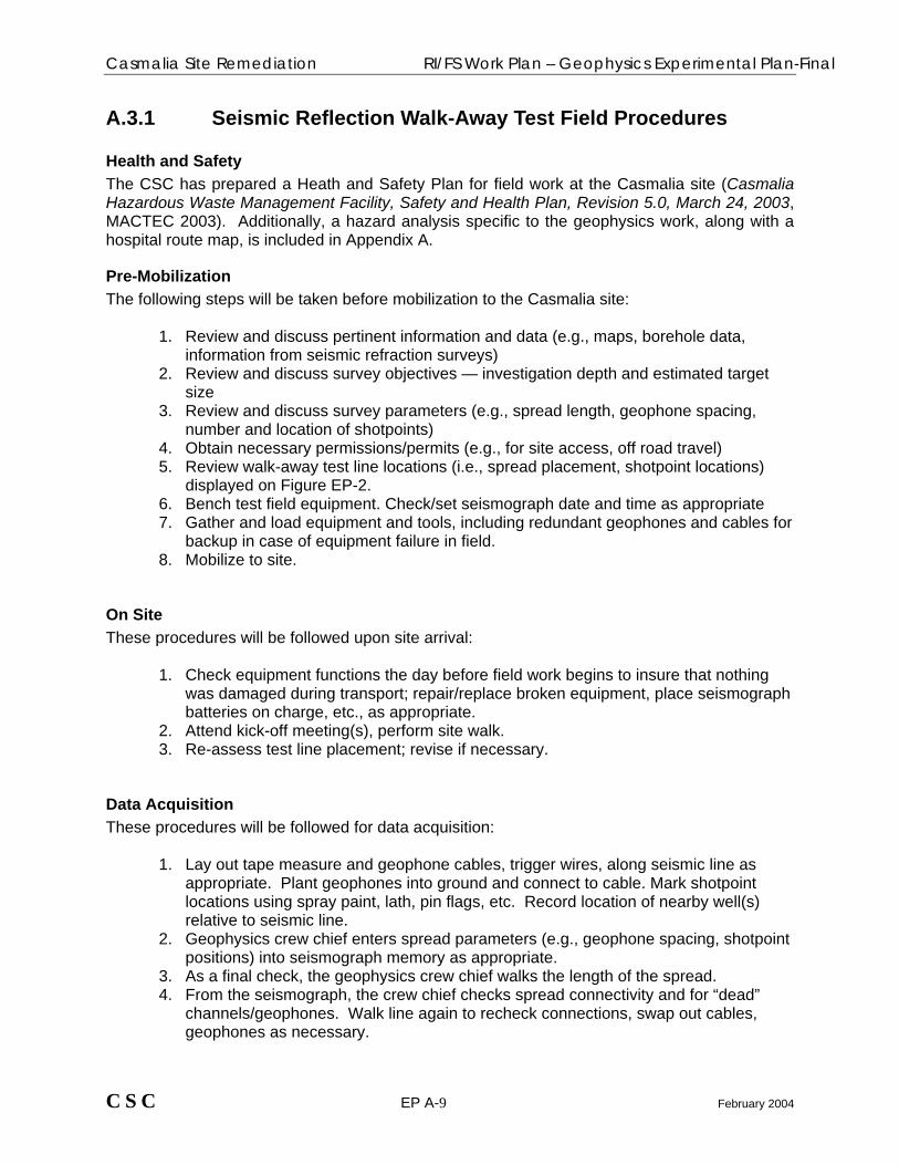
A.3.1 Seismic Reflection Walk-Away Test Field Procedures
Health and Safety The CSC has prepared a Heath and Safety Plan for field work at the Casmalia site (Casmalia Hazardous Waste Management Facility, Safety and Health Plan, Revision 5.0, March 24, 2003, MACTEC 2003). Additionally, a hazard analysis specific to the geophysics work, along with a hospital route map, is included in Appendix A.
Pre-Mobilization The following steps will be taken before mobilization to the Casmalia site:
1. Review and discuss pertinent information and data (e.g., maps, borehole data, information from seismic refraction surveys)
2. Review and discuss survey objectives — investigation depth and estimated target size
3. Review and discuss survey parameters (e.g., spread length, geophone spacing, number and location of shotpoints)
4. Obtain necessary permissions/permits (e.g., for site access, off road travel) 5. Review walk-away test line locations (i.e., spread placement, shotpoint locations)
displayed on Figure EP-2. 6. Bench test field equipment. Check/set seismograph date and time as appropriate 7. Gather and load equipment and tools, including redundant geophones and cables for
backup in case of equipment failure in field. 8. Mobilize to site.
On Site These procedures will be followed upon site arrival:
1. Check equipment functions the day before field work begins to insure that nothing was damaged during transport; repair/replace broken equipment, place seismograph batteries on charge, etc., as appropriate.
2. Attend kick-off meeting(s), perform site walk. 3. Re-assess test line placement; revise if necessary.
Data Acquisition These procedures will be followed for data acquisition:
1. Lay out tape measure and geophone cables, trigger wires, along seismic line as appropriate. Plant geophones into ground and connect to cable. Mark shotpoint locations using spray paint, lath, pin flags, etc. Record location of nearby well(s) relative to seismic line.
2. Geophysics crew chief enters spread parameters (e.g., geophone spacing, shotpoint positions) into seismograph memory as appropriate.
3. As a final check, the geophysics crew chief walks the length of the spread. 4. From the seismograph, the crew chief checks spread connectivity and for “dead”
channels/geophones. Walk line again to recheck connections, swap out cables, geophones as necessary.
C S C EP A-9 February 2004

Casmalia Site Remediation RI/FS Work Plan – Geophysics Experimental Plan-Final
5. Monitor for noise; adjust gains (if required). 6. Initiate seismic energy release at first shotpoint. Inspect resulting seismic record on
seismograph view screen. Check noise levels. Check first breaks. Check again for dead channels/geophones. No more than five (5) dead channels will be allowed.
7. Crew chief, with input from USEPA as appropriate, decides if record is acceptable. Decision will be made on the basis of apparent reflector continuity, noise level, and data completeness.
8. If record is acceptable, record data to seismograph memory 9. Record seismic data file name in field logbook. 10. Print and annotate final seismogram. Verify correct survey parameters as displayed
on seismogram hardcopy 11. Repeat for all shotpoints. 12. Test different energy source(s), as appropriate. 13. Land surveyor performs topographic survey along seismic line. 14. Plot and annotate actual walk-away test line location on basemap using existing site
features (e.g., monitoring wells) for reference. Use GPS if practicable. 15. Crew chief verifies that appropriate information (e.g., date, time, crew, line
designation & orientation, weather, noise conditions, etc.) has been recorded in field logbook.
16. Pick up spread. 17. Repeat steps 1 – 16 at second line location. 18. At day’s end: download data to laptop and backup to disk, if appropriate. 19. As appropriate, submit copy of data and field notes to USEPA
A.2.3 Seismic Reflection Data Management Seismic reflection data will be recorded in digital format onto the seismograph’s hard drive memory as the survey progresses. A separate data file will be created at each shotpoint, and each file will be assigned a unique file name that will identify the line name, shotpoint number, and seismic source type as appropriate. Additionally, the data will be output in hardcopy format (as seismograms- waveforms from each geophone) for each shotpoint. Pertinent information about each file (e.g., date, time, seismic source location, field conditions, crew names) will also be recorded in the geophysics crew chief’s field logbook. The logbook will be scanned periodically and the resulting image files will be named according to date and seismic line so the log entries can be readily correlated to the appropriate seismic data files. The scanned log book images will be incorporated into the digital data set. Digital data will be copied onto backup media each evening. A second backup set will be made and hand-delivered to the USEPA Casmalia site trailer. The CSC will keep the first backup set in its own field office. To track the data processing sequence, the names of the raw data files and associated processed data files, including those from filter tests and frequency analyses, will be tabulated on a worksheet. File names for resulting graphics products (e.g., filter panels, amplitude spectra) will also be tabulated as appropriate. Additionally, the graphics products will be annotated with creation dates and time and the names of the data files from which they were produced. It is expected that the raw seismic waveform data will be stored in a binary format read by the seismic processing software. To facilitate retrieval, data files associated with the modeling runs will be grouped according to seismic line. The raw data files for each shot point will be grouped in separate folders beneath each the seismic line folders. All files and the entire working directory structure will be burned to
C S C EP A-10 February 2004

Casmalia Site Remediation RI/FS Work Plan – Geophysics Experimental Plan-Final
a CD or DVD as appropriate and provided to the USEPA when the processing and modeling has been competed.
A.4 Micro-Gravity Micro-gravity measurements will be made within an approximately 1100- by 1100-foot area in the P/S Landfill. Measurement station locations are shown on Figure EP-2. Micro-gravity measurements will be made at 10-foot intervals along east-west and north-south alignments coincident with the seismic test lines so the results from the two surveys can be directly compared. The 10-foot station spacing will be used within a 600- by 750-foot area centered on the toe of the P/S Landfill. The measurement spacing will be expanded to 20 feet beyond the immediate landfill toe area. This will be done to maximize data coverage within the more limited level-of-effort framework of a test survey. Approximately 210 measurements will be obtained. Gravity measurements will be made using a Graviton-EG, Lacoste & Romberg’s new fully automated self-leveling gravimeter. Station locations will be measured with a fiberglass tape and marked with PVC pin flags or spray paint and will be surveyed by a licensed land surveyor to 0,01 foot accuracy to facilitate the topographic corrections necessary for optimal modeling and interpretation. A base station will be established near the survey area. The base station will be reoccupied approximately every three hours and at the beginning and end of each day to obtain repeat measurements that will enable time-varying instrument drift to be removed from the gravity data. Gravity measurements will be recorded in the instrument’s digital memory and in the geophysicist’s field log book along with pertinent information such as time and station designation as appropriate. Gravity data shall be processed and interpreted immediately after the field work is completed. Deliverables will include a copy of the geophysicist’s field log and appropriate data profiles (e.g., observed gravity, residual gravity, Bouguer anomaly) together with forward and inversion modeling results. The micro-gravity test survey will be performed in close communication with the USEPA and the CSC expects that a USEPA representative will be present during fieldwork to provide input and approve field decisions. The CSC will process and evaluate the data immediately upon completion of the fieldwork and, in conjunction with the USEPA, make a determination as to whether or not micro-gravity will be useful for delineating the Upper/Lower HSU contact, or the buried waste/native claystone contact, at the P/S Landfill. As part of the data evaluation, the CSC will provide the USEPA will all raw and processed data to facilitate agreement on data processing sequence and agreement on the final interpretation. The CSC will verbally discuss the results of the micro-gravity test survey with USEPA before the Pilot Study final report is issued. The CSC recognizes that removing the effects of the severe topography at the Casmalia site will be a critical part of the data processing sequence. Accordingly, the CSC will use three sources of topographic data for the terrain corrections: 1) Gravity measurement station elevations surveyed to 0.01 foot (vertical) by a licensed land surveyor as part of the micro-gravity test survey, 2) The most current of the detailed topographic data sets (2-foot contour interval) available for the Casmalia site, 3) regional topographic data derived from USGS topographic quadrangles. To perform the terrain correction, the raw gravity measurements and the topographic data will be input into the GEOSOFT Oasis montaj geophysical data processing
C S C EP A-11 February 2004
Casmalia Site Remediation RI/FS Work Plan – Geophysics Experimental Plan-Final
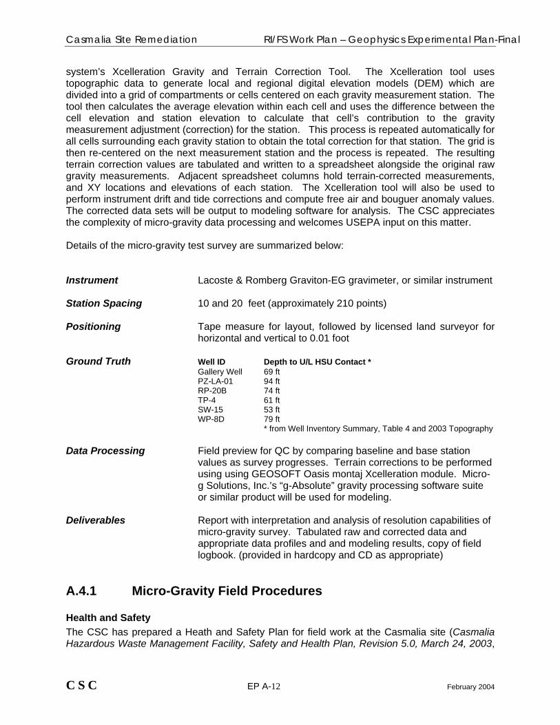
system’s Xcelleration Gravity and Terrain Correction Tool. The Xcelleration tool uses topographic data to generate local and regional digital elevation models (DEM) which are divided into a grid of compartments or cells centered on each gravity measurement station. The tool then calculates the average elevation within each cell and uses the difference between the cell elevation and station elevation to calculate that cell’s contribution to the gravity measurement adjustment (correction) for the station. This process is repeated automatically for all cells surrounding each gravity station to obtain the total correction for that station. The grid is then re-centered on the next measurement station and the process is repeated. The resulting terrain correction values are tabulated and written to a spreadsheet alongside the original raw gravity measurements. Adjacent spreadsheet columns hold terrain-corrected measurements, and XY locations and elevations of each station. The Xcelleration tool will also be used to perform instrument drift and tide corrections and compute free air and bouguer anomaly values. The corrected data sets will be output to modeling software for analysis. The CSC appreciates the complexity of micro-gravity data processing and welcomes USEPA input on this matter. Details of the micro-gravity test survey are summarized below: Instrument Lacoste & Romberg Graviton-EG gravimeter, or similar instrument Station Spacing 10 and 20 feet (approximately 210 points) Positioning Tape measure for layout, followed by licensed land surveyor for horizontal and vertical to 0.01 foot Ground Truth Well ID Depth to U/L HSU Contact * Gallery Well 69 ft PZ-LA-01 94 ft RP-20B 74 ft TP-4 61 ft
SW-15 53 ft WP-8D 79 ft * from Well Inventory Summary, Table 4 and 2003 Topography
Data Processing Field preview for QC by comparing baseline and base station
values as survey progresses. Terrain corrections to be performed using using GEOSOFT Oasis montaj Xcelleration module. Micro-g Solutions, Inc.’s “g-Absolute” gravity processing software suite or similar product will be used for modeling.
Deliverables Report with interpretation and analysis of resolution capabilities of micro-gravity survey. Tabulated raw and corrected data and appropriate data profiles and and modeling results, copy of field logbook. (provided in hardcopy and CD as appropriate)
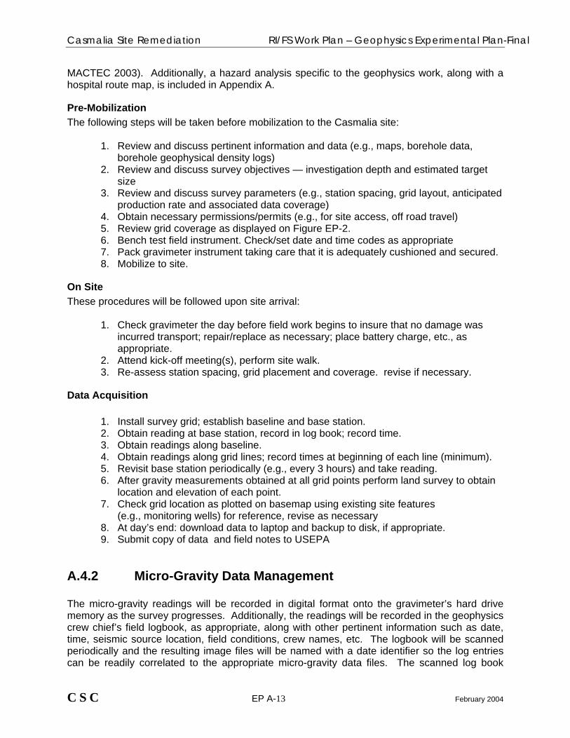
A.4.1 Micro-Gravity Field Procedures
Health and Safety The CSC has prepared a Heath and Safety Plan for field work at the Casmalia site (Casmalia Hazardous Waste Management Facility, Safety and Health Plan, Revision 5.0, March 24, 2003,
C S C EP A-12 February 2004
Casmalia Site Remediation RI/FS Work Plan – Geophysics Experimental Plan-Final
MACTEC 2003). Additionally, a hazard analysis specific to the geophysics work, along with a hospital route map, is included in Appendix A.
Pre-Mobilization The following steps will be taken before mobilization to the Casmalia site:
1. Review and discuss pertinent information and data (e.g., maps, borehole data, borehole geophysical density logs)
2. Review and discuss survey objectives — investigation depth and estimated target size
3. Review and discuss survey parameters (e.g., station spacing, grid layout, anticipated production rate and associated data coverage)
4. Obtain necessary permissions/permits (e.g., for site access, off road travel) 5. Review grid coverage as displayed on Figure EP-2. 6. Bench test field instrument. Check/set date and time codes as appropriate 7. Pack gravimeter instrument taking care that it is adequately cushioned and secured. 8. Mobilize to site.
On Site These procedures will be followed upon site arrival:
1. Check gravimeter the day before field work begins to insure that no damage was incurred transport; repair/replace as necessary; place battery charge, etc., as appropriate.
2. Attend kick-off meeting(s), perform site walk. 3. Re-assess station spacing, grid placement and coverage. revise if necessary.
Data Acquisition
1. Install survey grid; establish baseline and base station. 2. Obtain reading at base station, record in log book; record time. 3. Obtain readings along baseline. 4. Obtain readings along grid lines; record times at beginning of each line (minimum). 5. Revisit base station periodically (e.g., every 3 hours) and take reading. 6. After gravity measurements obtained at all grid points perform land survey to obtain
location and elevation of each point. 7. Check grid location as plotted on basemap using existing site features
(e.g., monitoring wells) for reference, revise as necessary 8. At day’s end: download data to laptop and backup to disk, if appropriate. 9. Submit copy of data and field notes to USEPA
A.4.2 Micro-Gravity Data Management The micro-gravity readings will be recorded in digital format onto the gravimeter’s hard drive memory as the survey progresses. Additionally, the readings will be recorded in the geophysics crew chief’s field logbook, as appropriate, along with other pertinent information such as date, time, seismic source location, field conditions, crew names, etc. The logbook will be scanned periodically and the resulting image files will be named with a date identifier so the log entries can be readily correlated to the appropriate micro-gravity data files. The scanned log book
C S C EP A-13 February 2004

Casmalia Site Remediation RI/FS Work Plan – Geophysics Experimental Plan-Final
images will be incorporated into the digital data set. In addition to the micro-gravity data, topographic data will also be obtained for each measurement station. The topographic data in the form of an X and Y coordinate and elevation, will be obtained in a separate survey by a licensed land surveyor and comprise a vital part of the micro-gravity data set. Digital data will be copied onto backup media each evening. A second backup set will be made and hand-delivered to the USEPA Casmalia site trailer. The CSC will keep the first backup set in its own field office. To track the data processing sequence, the names of the raw data files and associated processed data files will be tabulated on a worksheet. The CSC recognizes that terrain corrections are critical for micro-gravity data processing. Accordingly, the file name worksheet will correlate the model output with the appropriate terrain data set. File names for resulting graphics products (gravity profiles, 2D models, contour maps) will also be tabulated as appropriate. Additionally, the graphics products will be annotated with creation dates and time and the names of the data files from which they were produced. It is expected that the micro-gravity data will be stored in an a directly readable format such as ASCII text file. It is expected that the modeling runs will produce both raster and/or vector image files (e.g., .bmp and/or AutoCAD .dwg) and text files with the calculated depths to gravity layer interfaces beneath measurement stations. All files and the entire working directory structure will be burned to a CD or DVD as appropriate and provided to the USEPA when the processing and modeling has been competed.
C S C EP A-14 February 2004

Casmalia Site Remediation RI/FS Work Plan – Geophysics Experimental Plan
PART B – PRODUCTION SURVEY
B.1 Production Survey Overview A geophysical Production Survey using seismic refraction is planned for the Burial Trench Area, Central Drainage Area, and selected areas south of the PSCT trench (Figures EP-1, EP-3). The objective of the production survey is to search for potential low areas or depressions in the Upper/Lower HSU contact and for low areas in the native claystone surface beneath buried waste. As shown on Figure EP-3, the survey will be performed within an approximately 600- by 600-foot section of the Burial Trench Area, a 950- by 950 foot section of the Central Drainage Area, and a 2,000-foot long area extending approximately 300 feet south of the PSCT. Figure EP-3 shows the location of the 16 planned individual seismic refraction lines. To the extent possible, the lines are oriented parallel to slope contours and positioned along site roads to minimize topographic effects on the seismic data and to facilitate rapid data collection. Results from the seismic refraction portion of the Pilot Study will be incorporated into the production survey as appropriate. At present, the Experimental Plan calls for a geophone spacing of 12.5 feet to provide sufficient resolution potential to detect low spots on the order of 25 feet in diameter (although both the CSC and USEPA have acknowledged that a 25-foot target likely will not be detected below 75 feet bgs). Borehole data indicates that the depth to the UHSU/LHSU contact surface is on the order of 30 to 60 feet bgs in the Production Survey Area, increasing the likelihood that 25-foot wide target will be detected. The UHSU/LHSU contact depths are presented in Appendix K of the Remedial Investigation/ Feasibility Study (RI/FS) Work Plan and are also included in Appendix B. A 96-channel seismic system such as the Geometrics StrataVisor will be used, resulting in spreads up to 1200 feet long with a potential investigation depth of at least 150 feet. The seismic spreads in the Burial Trench Area have been shortened to approximately 800 feet, corresponding to a potential investigation depth of 100 feet. Five shotpoints per spread will be used to facilitate data processing and interpretation using the generalized reciprocal method (GRM), a technique for delineating undulating refractors (contacts). Seismic energy will be produced with an accelerated weight drop system such as the Geometrics PWD-80, a highly mobile pickup truck mounted system that can be readily moved along the seismic line. The seismic refraction Production Survey will be performed in close communication with the USEPA and the CSC expects that a USEPA representative will be present during fieldwork to provide input and approve field decisions. The CSC will process and evaluate the data as the survey progresses. As part of the data evaluation, the CSC will provide the USEPA will all raw and processed data to facilitate agreement on data processing sequence and agreement on the final interpretation. The CSC will verbally discuss the results of the refraction production with USEPA and specifically advise of any potential low areas indicated. Final production survey results will be presented in the RI/FS report. The report will include a discussion of the results, the interpretation, and any problems encountered. The report will also include a description of equipment and field procedures. The report will include a basemap showing seismic line locations and contour maps showing the elevation of the interpreted Upper/Lower HSU contact. Raw data, along with TD plots and velocity layer model depth sections will also be included. Details of the seismic refraction Production Survey are summarized below:
C S C EP B-1 3/13/2008

Casmalia Site Remediation RI/FS Work Plan – Geophysics Experimental Plan
Investigation Depth up to 150 feet bgs Spread Length 800 to 1200 feet
Geophone Spacing 12.5 feet, nominal Seismograph Geometrics StrataVisor, or equivalent Seismic Source Geometrics PWD-80, or equivalent Shotpoint Spacing 300 feet (nominal), five shotpoints per spread Positioning Tape measure for layout, followed by licensed land surveyor for horizontal and vertical to 0.01 foot Ground Truth (See Appendix B) Data Processing Field preview for QC using seismograph software on-board
Final processing using Generalized Reciprocal Method (GRM) software
Deliverables Report with location map, interpreted velocity profiles, TD plots,
raw data with first break picks, copy of field logbook. (provided in hardcopy and CD as appropriate)
B.2 Seismic Refraction Field Procedures
Health and Safety The CSC has prepared a Heath and Safety Plan for field work at the Casmalia site (Casmalia Hazardous Waste Management Facility, Safety and Health Plan, Revision 5.0, March 24, 2003, MACTEC 2003). Additionally, a hazard analysis specific to the geophysics work, along with a hospital route map, is included in Appendix A.
Pre-Mobilization The following steps will be taken before mobilization to the Casmalia site:
1. Review and discuss pertinent information and data (e.g., maps, borehole data, results of previous refraction surveys)
2. Review and discuss survey objectives — investigation depth and estimated target size
3. Review and discuss survey parameters (e.g., spread length, geophone spacing, number of shotpoints)
4. Obtain necessary permissions/permits (e.g., for site access, off road travel) 5. Review seismic survey coverage (i.e., spread placement, shotpoint locations)
displayed on Figure EP-3. 6. Bench test field equipment. Check/set seismograph date and time as appropriate
C S C EP B-2 3/13/2008

Casmalia Site Remediation RI/FS Work Plan – Geophysics Experimental Plan
7. Gather and load equipment and tools, including redundant geophones and cables for backup in case of equipment failure in field.
8. Mobilize to site.
On Site These procedures will be followed upon site arrival:
1. Check equipment functions the day before field work begins to insure that nothing was damaged during transport; repair/replace broken equipment, place seismograph batteries on charge, etc., as appropriate.
2. Attend kick-off meeting(s), perform site walk. 3. Re-assess seismic line placement; revise if necessary.
Data Acquisition These procedures will be followed for data acquisition:
1. Lay out tape measure and geophone cables, trigger wires, along seismic line as appropriate. Plant geophones into ground and connect to cable. Mark shotpoint locations using spray paint, lath, pin flags, etc. Record location of nearby well(s) relative to seismic line.
2. Geophysics crew chief enters spread parameters (e.g., geophone spacing, shotpoint positions) into seismograph memory as appropriate.
3. As a final check, the geophysics crew chief walks the length of the spread. 4. From the seismograph, the crew chief checks spread connectivity and for “dead”
channels/geophones. Walk line again to recheck connections, swap out cables, geophones as necessary.
5. Monitor for noise; adjust gains (if required). 6. Initiate seismic energy release at first shotpoint. Inspect resulting seismic record on
seismograph view screen. Check noise levels. Check first breaks. Check again for dead channels/geophones. No more than five (5) dead channels will be allowed.
7. Crew chief, with input from USEPA as appropriate, decides if record is acceptable. Decision will be made on the basis of first break quality, noise level, and data completeness.
8. If record is acceptable, record data to seismograph memory 9. Stack data from additional shots as appropriate. 10. Record seismic data file name in field logbook. 11. Print and annotate final seismogram. Verify correct survey parameters as displayed
on seismogram hardcopy. 12. Repeat for all shotpoints along spread. 13. Interpret data and perform preliminary analysis and modeling in field to assess
investigation depth and plausibility of velocity layering 14. Land surveyor performs topographic survey along seismic line. 15. Plot and annotate actual seismic line location on basemap using existing site
features (e.g., monitoring wells) for reference. Use GPS if practicable. 16. Crew chief verifies that appropriate information (e.g., date, time, crew, line
designation & orientation, weather, noise conditions, etc.) has been recorded in field logbook.
17. Pick up spread.
C S C EP B-3 3/13/2008

Casmalia Site Remediation RI/FS Work Plan – Geophysics Experimental Plan
18. Repeat steps 1 – 17 at next line location. 19. At day’s end: download data to laptop and backup to disk, if appropriate. 20. As appropriate, submit copy of data and field notes to USEPA
B.3 Seismic Refraction Data Management Seismic refraction data will be recorded in digital format onto the seismograph’s hard drive memory as the survey progresses. A separate data file will be created at each shotpoint, and each file will be assigned a unique file name that will identify the line name and shotpoint number. Additionally, the data will be output in hardcopy format (as seismograms- waveforms from each geophone) for each shotpoint. Pertinent information about each file (e.g., date, time, seismic source location, field conditions, crew names) will also be recorded in the geophysics crew chief’s field logbook. The logbook will be scanned periodically and the resulting image files will be named according to date and seismic line so the log entries can be readily correlated to the appropriate seismic data files. The scanned log book images will be incorporated into the digital data set. Digital data will be copied onto backup media each evening. A second backup set will be made and hand-delivered to the USEPA Casmalia site trailer. The CSC will keep the first backup set in its own field office. To track the data processing sequence, the names of the raw data files and associated processed data files, including those from velocity layer modeling runs, will be tabulated on a worksheet. File names for resulting graphics products (TD plots, velocity profiles, contour maps) will also be tabulated as appropriate. Additionally, the graphics products will be annotated with creation dates and time and the names of the data files from which they were produced. In particular, computer generated contour maps will be annotated with appropriate contouring parameters such as grid cell size and gridding algorithm used. It is expected that the raw seismic waveform data will be stored in a binary format read by the processing software, while the TD and contouring data sets will be stored in an a directly readable format such as an EXCEL worksheet or ASCII text file. It is expected that the modeling runs will produce both raster and/or vector image files (e.g., .bmp and/or AutoCAD .dwg) and text files with the calculated depths to velocity layer interfaces beneath shotpoints and geophones along each seismic line. To facilitate retrieval, data files associated with the modeling runs will be grouped according to seismic line. The raw data files for each shot point will be grouped in separate folders beneath each the seismic line folders. All files and the entire working directory structure will be burned to a CD or DVD as appropriate and provided to the USEPA when the processing and modeling has been competed.
C S C EP B-4 3/13/2008

Casmalia Site Remediation RI/FS Work Plan – Geophysics Experimental Plan
Attachments: Figure EP-1 Pilot Study and Production Survey Area Map Figure EP-2 Pilot Study Line and Grid Point Locations Figure EP-3 Production Survey Line Locations Figure EP-4 Hospital Route Map Appendix A Geophysical Survey Hazard Analysis Appendix B Well Inventory Summary, Table 4
C S C EP B-5 3/13/2008


Casmalia Site Remediation RI/FS Work Plan – Geophysics Experimental Plan
APPENDIX A
Geophysical Survey Hazard Analysis
C S C EP B-6 3/13/2008

Casmalia Site Remediation RI/FS Work Plan – Geophysics Experimental Plan
Geophysical Survey Hazard Analysis
Work Activity:
Personal Protective Equipment (PPE):
Goggles
Face Shields
Safety Glasses
Lifeline/Body Harness
Hard Hat
Cold weather steel toed boots
Chemical resistant steel toed bootsc
Supplied Respirator
Air Purifying Respiratora
Welding/Pipe Clothing
Welding Mask/Goggles
Life Vest
Glovesc
Coverallsc
Hearing protectionb
Analyzed By Position/Title Reviewed By Position/Title Date Roark Smith Senior Geophysicist Peter B. Rice, C.I.H., C.S.P. Principal Safety and IH Specialist 2/26/04
Job Steps Potential Hazards Critical Actions 1. Set up seismic survey transect. Mechanical hazards – operating machinery
and mechanized equipment (1,2,3,4)f Administrative – only qualifiedd operators using equipment, tools
2. Layout sensor arrays. Acoustical hazards – loud and/or sustained noise (1,2,3,4)f
Hazard inspection and monitoring – noise Wear hearing protection at all times
3. Establish shot points and initialize energy source.
Electrical hazards from geophysical equipment power supply (2,3,4)f
Engineering – check power cables & connections for wear. Cover batteries with insulated shield
4. Obtain seismic data. Physical hazards – slips, trips, and falls, extreme temperatures, uneven terrain, vibration (1,2,3,4,5,6,7)f
Stand clear of stand clear of weight drop system and equipment power supply. Monitor temperature and wind, wear appropriate weather clothing, take breaks, drink fluids, eat often
5. Set up micro-gravity survey grid.
Ergonomic hazards – lifting, repetitive motions (1,2,3,4,5,6,7)f
Use proper lifting techniques. Do not overload while hand-carrying equipment
6. Obtain micro-gravity data. Chemical hazards – exposure to airborne contaminants, contaminated soil, battery acid (1,2,3,4,5,6,7)
Wear appropriate PPEe (as defined at top of page), personnel decontamination, monitor dust if visible
7. Perform land survey . Biological hazards – spiders, snakes, mountain lion, badgers (1,2,3,4,5,6,7)f
Keep site clean of animal-attracting smells, remain aware of surroundings, and monitor animal activity in the area
Equipment to be Used Inspection Requirements Training Requirements
Weight drop impulse energy system. Equipment Safety Checklist Project-specific, initial health and safety briefing Hand tools Visual inspection daily and before each
use Pre-shift tailgate safety briefings. Review this Job Hazard Analysis
Seismograph, geophones, and cables. Visual inspection of geophones and cables, test effective operation of seismograph with on board functionality tests.
Hazardous Waste Operations training for employees performing tasks associated with hazardous wastes
Gravimeter Verify operational status and occupy set base station daily.
First Aid & CPR for a least two employees onsite per shift
Truck Vehicle/Equipment Safety Checklist Site specific training on biological hazards a Respiratory protection will be used if dust or contaminants become a problem. Dust will be monitored visually and by respiratory/nasal
irritation. A respirator will be used if TOV readings are above 1 ppm (sustained for 1 minute) in the breathing zone as measured with a PID. Full face respirators will be used when TOV readings are above 10 ppm.
b Noise protection will be used whenever sound-pressure levels exceed 85 decibels steady state (when normal communications becomes difficult at 3 feet) or 140 decibels impulse, regardless of the duration of exposure.
c As necessary to prevent or minimize exposure as determined by the SSHO. d Qualified: Training and experience with tasks, hazards, and safe work practices as determined by the employer. e SSHO will make the final determination on proper PPE. f Numbers correspond to job steps
C S C EP B-7 3/13/2008

Casmalia Site Remediation RI/FS Work Plan – Geophysics Experimental Plan
APPENDIX B
Well Inventory Summary, Including UHSU/LHSU Contact
Elevations
C S C EP B-8 3/13/2008

Table 4Well Construction Details
Well Inventory ReportCasmalia, California
Well Name Well Type
Modifications Since Original Construction
TOC Elevation (ft
MSL)
Ground Surface
Elevation (ft MSL)
Well Casing
Diameter (in)
Well Casing Material
Depth of Boring (ft
bgs)
Total Well
Depth (ft bgs)
Bottom of Casing
Elevation (ft MSL)
Top of Screen
Depth (ft bgs)
Top of Screen Elevatio
n (ft MSL)
Bottom of Screen Depth (ft bgs)
Bottom of Screen
Elevation (ft MSL)
Lithology of Screened Interval
Depth to Weathered/
Unweathered Contact (ft bgs)
Elevation of Weathered/
Unweathered Contact (ft MSL)
Water level Depth (feet) Locked ? Comments
A1-B WL Yes 759.78 757.8* 6 PVC 357 148.9 608.9 123.8 634 147.8 610 U 5.9 751.9 93.65 Yes Casing reduced
A1M WL Yes 726.51 723.50 6 PVC 180 176 547.502 18.502 705 176.002 547.5 W/U 46 677.502 46.71 Yes Casing reduced
A2B CQ No 453.25 452.63 6 PVC 61 61 391.632 36.632 416 56.632 396 U 34 418.632 20.41 Yes
A2M WL No 419.40 416.14 6 PVC 18 18 398.143 7.143 405.5 12.643 400 W 15 401.143 6.42 Yes
B3B CQ No 384.88 384.22 6 PVC 70 65 319.216 39.216 345 63.216 321 U 25 359.216 46.82 Yes
B3M CQ No 386.56 384.14 4 PVC 25 25 359.137 8.137 376 20.637 363.5 A NE 13.9 Yes
B4M WL No 370.70 367.92 4 PVC 25 26 341.918 10.918 356.6 23.918 344.1 A NE 5.85 Yes Well ID changed from B4M2 to match log
B-5 CQ No 407.72 405.00 8 PVC 45 359.996 27 380.72 NA GCW NA 31.52 Yes Gallery collection well
B6B WL Yes 401.27 398.93 6 PVC 62 62 336.933 50.433 349.8 60.433 339.8 U 37 361.933 38.16 Yes Casing added
C1B WL No 439.52 435.98 6 PVC 87 87 348.983 71.483 361 81.483 351 U 62 373.983 25.23 Yes
C2B WL No 452.31 449.02 6 PVC 95 95 354.021 83.021 366.1 93.021 356.1 U 70 379.021 39.89 Yes
C2M WL No 448.92 445.54 6 PVC 58 58 387.542 7.042 435 52.542 390 F/W 55 390.542 31.64 Yes
C3M CQ No 418.10 415.85 4 PVC 40 40 375.853 17.853 398 38.853 377 W 37 378.853 9.11 Yes
C4M CQ No 456.57 453.23 6 PVC 90 89 364.231 7.231 446 83.731 369.5 F/W 86.5 366.731 49.11 Yes
C-5 CQ No 452.38 451.06 PVC NA 50 NA 70 NA GCW NE 53.2 No
C5E WL No 452.49 451.59 6 PVC NA NA NA GCW NE 46.2 Yes
C6B WL No 454.30 451.29 6 PVC 106 106 345.289 91.289 360 100.789 350.5 U 90.5 360.789 46.95 Yes
CD-1 WL No 452.76 450.23 2 PVC NA NA NA NA NE 16 Yes
CD-2 WL No 449.23 448.20 4 PVC NA NA NA NA NE 25.31 Yes
CpH WL No 436.66 436.09 2 PVC 120 121 315.085 110.085 326 120.085 316 U 101 335.085 26.35 Yes
D1B CQ No 479.55 478.86 6 PVC 130 103 375.856 77.856 401 101.856 377 U 47 431.856 14.81 Yes
D1M WL No 479.05 475.48 6 PVC 47 47 428.478 7.478 468 41.978 433.5 W 44 431.478 12.19 Yes
DB-1 CQ No 482.24 481.75 4 PVC 53.5 53 428.751 42.831 439 52.831 429 U 9 472.751 17.38 Yes
Table4_Well Construction Details.xls.xls-C9/8/04 1 of 15
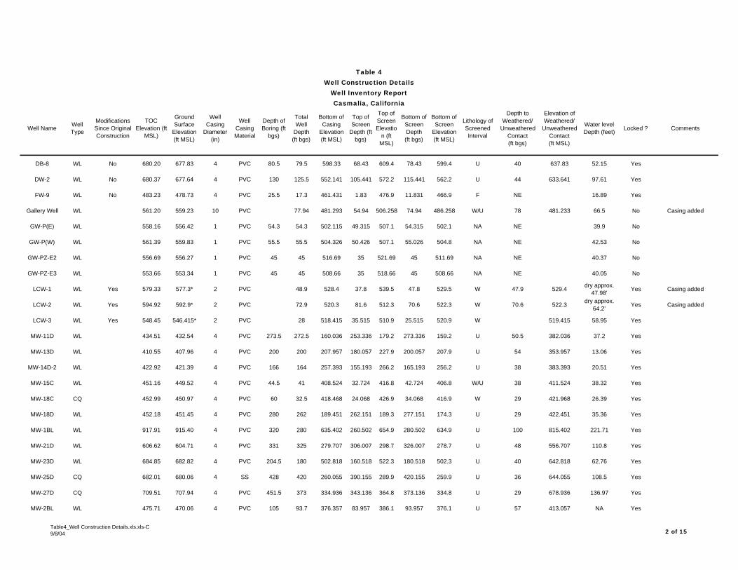
Table 4Well Construction Details
Well Inventory ReportCasmalia, California
Well Name Well Type
Modifications Since Original Construction
TOC Elevation (ft
MSL)
Ground Surface
Elevation (ft MSL)
Well Casing
Diameter (in)
Well Casing Material
Depth of Boring (ft
bgs)
Total Well
Depth (ft bgs)
Bottom of Casing
Elevation (ft MSL)
Top of Screen
Depth (ft bgs)
Top of Screen Elevatio
n (ft MSL)
Bottom of Screen Depth (ft bgs)
Bottom of Screen
Elevation (ft MSL)
Lithology of Screened Interval
Depth to Weathered/
Unweathered Contact (ft bgs)
Elevation of Weathered/
Unweathered Contact (ft MSL)
Water level Depth (feet) Locked ? Comments
DB-8 WL No 680.20 677.83 4 PVC 80.5 79.5 598.33 68.43 609.4 78.43 599.4 U 40 637.83 52.15 Yes
DW-2 WL No 680.37 677.64 4 PVC 130 125.5 552.141 105.441 572.2 115.441 562.2 U 44 633.641 97.61 Yes
FW-9 WL No 483.23 478.73 4 PVC 25.5 17.3 461.431 1.83 476.9 11.831 466.9 F NE 16.89 Yes
Gallery Well WL 561.20 559.23 10 PVC 77.94 481.293 54.94 506.258 74.94 486.258 W/U 78 481.233 66.5 No Casing added
GW-P(E) WL 558.16 556.42 1 PVC 54.3 54.3 502.115 49.315 507.1 54.315 502.1 NA NE 39.9 No
GW-P(W) WL 561.39 559.83 1 PVC 55.5 55.5 504.326 50.426 507.1 55.026 504.8 NA NE 42.53 No
GW-PZ-E2 WL 556.69 556.27 1 PVC 45 45 516.69 35 521.69 45 511.69 NA NE 40.37 No
GW-PZ-E3 WL 553.66 553.34 1 PVC 45 45 508.66 35 518.66 45 508.66 NA NE 40.05 No
LCW-1 WL Yes 579.33 577.3* 2 PVC 48.9 528.4 37.8 539.5 47.8 529.5 W 47.9 529.4 dry approx. 47.98' Yes Casing added
LCW-2 WL Yes 594.92 592.9* 2 PVC 72.9 520.3 81.6 512.3 70.6 522.3 W 70.6 522.3 dry approx. 64.2' Yes Casing added
LCW-3 WL Yes 548.45 546.415* 2 PVC 28 518.415 35.515 510.9 25.515 520.9 W 519.415 58.95 Yes
MW-11D WL 434.51 432.54 4 PVC 273.5 272.5 160.036 253.336 179.2 273.336 159.2 U 50.5 382.036 37.2 Yes
MW-13D WL 410.55 407.96 4 PVC 200 200 207.957 180.057 227.9 200.057 207.9 U 54 353.957 13.06 Yes
MW-14D-2 WL 422.92 421.39 4 PVC 166 164 257.393 155.193 266.2 165.193 256.2 U 38 383.393 20.51 Yes
MW-15C WL 451.16 449.52 4 PVC 44.5 41 408.524 32.724 416.8 42.724 406.8 W/U 38 411.524 38.32 Yes
MW-18C CQ 452.99 450.97 4 PVC 60 32.5 418.468 24.068 426.9 34.068 416.9 W 29 421.968 26.39 Yes
MW-18D WL 452.18 451.45 4 PVC 280 262 189.451 262.151 189.3 277.151 174.3 U 29 422.451 35.36 Yes
MW-1BL WL 917.91 915.40 4 PVC 320 280 635.402 260.502 654.9 280.502 634.9 U 100 815.402 221.71 Yes
MW-21D WL 606.62 604.71 4 PVC 331 325 279.707 306.007 298.7 326.007 278.7 U 48 556.707 110.8 Yes
MW-23D WL 684.85 682.82 4 PVC 204.5 180 502.818 160.518 522.3 180.518 502.3 U 40 642.818 62.76 Yes
MW-25D CQ 682.01 680.06 4 SS 428 420 260.055 390.155 289.9 420.155 259.9 U 36 644.055 108.5 Yes
MW-27D CQ 709.51 707.94 4 PVC 451.5 373 334.936 343.136 364.8 373.136 334.8 U 29 678.936 136.97 Yes
MW-2BL WL 475.71 470.06 4 PVC 105 93.7 376.357 83.957 386.1 93.957 376.1 U 57 413.057 NA Yes
Table4_Well Construction Details.xls.xls-C9/8/04 2 of 15

Table 4Well Construction Details
Well Inventory ReportCasmalia, California
Well Name Well Type
Modifications Since Original Construction
TOC Elevation (ft
MSL)
Ground Surface
Elevation (ft MSL)
Well Casing
Diameter (in)
Well Casing Material
Depth of Boring (ft
bgs)
Total Well
Depth (ft bgs)
Bottom of Casing
Elevation (ft MSL)
Top of Screen
Depth (ft bgs)
Top of Screen Elevatio
n (ft MSL)
Bottom of Screen Depth (ft bgs)
Bottom of Screen
Elevation (ft MSL)
Lithology of Screened Interval
Depth to Weathered/
Unweathered Contact (ft bgs)
Elevation of Weathered/
Unweathered Contact (ft MSL)
Water level Depth (feet) Locked ? Comments
MW-2BU WL 579.89 577.97 4 PVC 44.5 43.5 534.467 33.867 544.1 43.867 534.1 W NA 28.98 Yes
MW-3BL WL 549.35 547.66 4 PVC 220 216 331.661 196.661 351 216.661 331 U 34 513.661 15.74 Yes
MW-3BU WL 510.25 508.24 4 PVC 55 49 459.237 38.837 469.4 48.837 459.4 W 51 457.237 10.43 Yes
MW-4BL WL 505.80 503.98 4 PVC 139 115 388.984 106.084 397.9 116.084 387.9 U 40 463.984 26.45 Yes
MW-4BU WL 510.51 507.53 4 PVC 44 44 463.531 33.531 474 43.531 464 U 30 477.531 25.72 Yes
MW-5BL WL 510.74 508.63 4 PVC 130 120 388.63 110.73 397.9 120.73 387.9 U 56 452.63 7.15 Yes
MW-5BU WL 472.12 469.87 4 PVC 53 53 416.873 43.943 425.93 53.943 415.93 U 39 430.873 0.05 Yes
MW-6D WL 457.21 455.60 4 PVC 170.9 169 286.6 149.4 306.2 169.4 286.2 U 29 426.6 29.4 Yes
MW-7BL WL 904.02 901.45 4 PVC 325 320 581.445 300.245 601.2 321.245 581.2 U 90 811.445 219.47 Yes
MW-7BU CQ 615.26 614.41 4 PVC 52.8 57 557.413 46.813 567.6 56.813 557.6 W 52 562.413 30.47 Yes
MW-7C CQ 454.00 452.18 4 PVC 100 85.5 366.684 80.084 372.1 90.084 362.1 U 76 376.184 46.09 Yes
MW-7D CQ 454.20 451.92 4 PVC 173.5 172.5 279.421 152.821 299.1 172.821 279.1 U 86 365.921 46.28 Yes
MW-8D-2 WL 456.04 454.05 4 PVC 250 204.048 187.848 272.6 197.848 252.6 U 35 419.048 46.01 Yes
NP-11 WL 666.12 663.78 4 STEEL 35 628.779 NA NA N/A NE _ Yes
NP-8 WL 694.13 695.11 4 STEEL 24 671.107 NA NA N/A 20 675.107 24.1 Yes
PSCT-1 CQ 454.51 450.99 8 PVC 53.18 397.81 43.919 407.07 52.419 398.57 W NE 31.6 No
PSCT-2 CQ 503.51 502.49 8 PVC 61.89 440.60 54.093 448.4 62.493 440 W NE 48.91 No
PSCT-3 CQ 561.34 560.03 8 PVC 65.94 494.09 55.681 504.35 63.981 496.05 W NE 55.41 No
PSCT-4 CQ 593.18 591.17 8 PVC 66.15 525.02 47.298 543.87 65.198 525.97 W NE 47.49 No
PZ-LA-01 WL Yes 595.65 595.43 0.75 PVC 97 97 498.65 87 508.65 97 498.65 W/U 94 501.65 _ No Casing collapsed @71' bgs
PZ-P18-1 WL 458.76 456.80 2 PVC 45 45 411.801 28.252 426.229 43.252 411.229 F/A NE 15.71 Yes
PZ-P18-2A WL 476.85 474.56 2 PVC 20 454.56 12.858 459.092 17.858 454.092 F/A NE dry 26.84' Yes
PZ-P18-2B WL 476.85 474.56 2 PVC 35 32 442.56 24.858 447.022 29.858 442.022 F/A NE dry 26.84' Yes
Table4_Well Construction Details.xls.xls-C9/8/04 3 of 15

Table 4Well Construction Details
Well Inventory ReportCasmalia, California
Well Name Well Type
Modifications Since Original Construction
TOC Elevation (ft
MSL)
Ground Surface
Elevation (ft MSL)
Well Casing
Diameter (in)
Well Casing Material
Depth of Boring (ft
bgs)
Total Well
Depth (ft bgs)
Bottom of Casing
Elevation (ft MSL)
Top of Screen
Depth (ft bgs)
Top of Screen Elevatio
n (ft MSL)
Bottom of Screen Depth (ft bgs)
Bottom of Screen
Elevation (ft MSL)
Lithology of Screened Interval
Depth to Weathered/
Unweathered Contact (ft bgs)
Elevation of Weathered/
Unweathered Contact (ft MSL)
Water level Depth (feet) Locked ? Comments
PZ-P18-3A WL 477.84 475.22 2 PVC 45 20 455.215 12.544 459.701 17.544 454.701 F/A NE dry 30.38' Yes
PZ-P18-3B WL 477.83 475.22 2 PVC 45 35 440.215 27.544 444.691 32.544 439.691 W NE dry 30.38' Yes
PZ-P18-4A WL 478.03 475.77 2 PVC 45 20 455.772 12.946 460.126 17.946 455.126 F/A NE dry 32.03' Yes
PZ-P18-4B WL 478.00 475.77 2 PVC 45 45 430.772 32.946 440.176 42.946 430.176 F/A NE dry 32.03' Yes
PZ-P18-5 WL/CQ 470.96 468.60 2 PVC 45 40 428.596 32.827 432.889 37.827 427.889 W 40.5 428.096 26.25 Yes
PZ-PA5-1A WL 475.89 473.37 2 PVC 25 25 448.366 17.676 452.61 22.676 447.61 F/A NE 17.11 Yes
PZ-PA5-1A1 WL 475.89 473.37 2 PVC 25 15 458.366 2.672 467.62 12.672 457.62 F/A NE dry at 18.2' Yes
PZ-PA5-2A WL 475.72 473.25 2 PVC 50 25 448.245 12.751 457.85 22.751 447.85 F/A NE 16.51 Yes
PZ-PA5-2B WL 475.71 473.25 2 PVC 50 35 438.245 27.711 443.03 32.711 438.03 F/A NE 18.86 Yes
PZ-PA5-2C WL 475.72 473.25 2 PVC 50 45 428.245 37.713 432.792 42.713 427.792 F/A NE 23.22 Yes
PZ-PA5-3A WL 473.98 471.42 2 PVC 45 23 448.421 10.598 458.22 20.598 448.22 F/A NE 16.91 Yes
PZ-PA5-3A1 WL 473.93 471.42 2 PVC 45 9 462.421 1.689 467.22 6.689 462.22 F/A NE 11.21 Yes
PZ-PA5-3B WL 474.04 471.42 2 PVC 45 33 438.421 25.585 443.276 30.585 438.276 F/A NE 19.56 Yes
PZ-PA5-3C WL 474.08 471.42 2 PVC 45 43 428.421 35.565 443.126 40.565 428.126 F/A NE 18.05 Yes
RAP-1A CQ 449.40 448.13 8 PVC 37.5 410.628 20.128 428 37.128 409 W/U 22.8 425.328 35.65 No
RAP-1B CQ 416.07 413.70 8 PVC 69.7 344.002 50.502 363.2 70.002 343.7 W/U 56.9 356.802 58.16 No
RAP-1C CQ 450.67 447.09 8 PVC 64.5 382.59 45.09 402 64.09 383 W/U 50 397.09 60.71 No
RAP-2A WL 447.10 445.32 8 PVC 52.8 392.521 34.821 410.5 54.121 391.2 W/U 36.5 408.821 50.72 No
RAP-3A CQ 423.05 421.15 8 PVC 51.6 369.554 33.154 388 52.154 369 W/U 37.5 383.654 50.85 No
RIMW-1 CQ 496.75 494.69 4 PVC 40 30.5 464.19 10 484.69 30 464.69 U 8 486.69 9.45 Yes
RIMW-2 CQ 457.60 455.65 4 PVC 45 40.5 415.15 20 435.65 40 415.65 W/U 25.5 430.15 5.16 Yes
RIMW-3 CQ 482.50 480.29 4 PVC 35 31.5 448.79 6 474.29 31 449.29 A/W NE 5.24 Yes
RIMW-5 CQ 592.64 590.56 4 PVC 65 60.5 530.06 40 550.56 60 530.56 U 31 559.56 57.04 Yes
Table4_Well Construction Details.xls.xls-C9/8/04 4 of 15

Table 4Well Construction Details
Well Inventory ReportCasmalia, California
Well Name Well Type
Modifications Since Original Construction
TOC Elevation (ft
MSL)
Ground Surface
Elevation (ft MSL)
Well Casing
Diameter (in)
Well Casing Material
Depth of Boring (ft
bgs)
Total Well
Depth (ft bgs)
Bottom of Casing
Elevation (ft MSL)
Top of Screen
Depth (ft bgs)
Top of Screen Elevatio
n (ft MSL)
Bottom of Screen Depth (ft bgs)
Bottom of Screen
Elevation (ft MSL)
Lithology of Screened Interval
Depth to Weathered/
Unweathered Contact (ft bgs)
Elevation of Weathered/
Unweathered Contact (ft MSL)
Water level Depth (feet) Locked ? Comments
RIMW-6 CQ 618.10 616.09 4 PVC 70.5 70.5 545.59 45 571.09 70 546.09 U 38 578.09 72.08 Yes
RIMW-7 CQ 641.36 639.38 4 PVC 80 75.5 563.88 50 589.38 75 564.38 F/A 64 575.38 58.6 Yes
RIMW-8 CQ 658.93 656.92 4 PVC 70 65.5 591.42 45 611.92 65 591.92 W/U 60 596.92 39.18 Yes
RIMW-9 CQ 453.96 452.11 4 PVC 67 63.5 388.61 43 409.11 63 389.11 F/A NE 46.4 Yes
RIPZ-2 WL 399.49 397.40 2 PVC 50.5 50.5 346.90 35 362.40 50 347.40 W/U 42.3 355.10 19.9 Yes
RIPZ-3 WL 444.12 441.65 0.75 PVC 34.5 27 414.65 17 424.65 27 414.65 A/W 34.5 407.15 13.32 Yes
RIPZ-4 WL 448.34 445.69 0.75 PVC 34 32.5 413.19 22.5 423.19 32.5 413.19 W NE 20.56 Yes
RIPZ-5 WL 451.09 451.74 2 PVC 65 64.5 387.24 44 407.74 64 387.74 F/A NE 42.08 Yes
RIPZ-6 WL 465.87 463.82 2 PVC 51 50.5 413.32 30 433.82 50 413.82 U 20.5 443.32 46.23 Yes
RIPZ-7 WL 480.44 477.71 0.75 PVC 38 33.2 444.51 23.2 454.51 33.2 444.51 F/A NE 19.23 Yes
RIPZ-8 CQ 531.35 529.00 2 PVC 62 32.5 496.50 12 517.00 32 497.00 W/U 30 499.00 13.58 Yes
RIPZ-9 WL 594.92 592.94 2 PVC 65.5 65.5 527.44 50 542.94 65 527.94 U 26 566.94 44.78 Yes
RIPZ-10B WL 747.01 744.92 2 PVC 86 85.5 659.42 55 689.92 85 659.92 U 31 713.92 75.03 Yes
RIPZ-10C WL 746.44 744.46 2 PVC 136 135.5 608.96 115 629.46 135 609.46 U 30 714.46 118.69 Yes
RIPZ-10D WL 746.48 744.68 2 PVC 240 220.5 524.18 200 544.68 220 524.68 U 30 714.68 162.11 Yes
RIPZ-11 WL 487.24 485.23 2 PVC 65 50.5 434.73 30 455.23 50 435.23 U 31.8 453.43 27.21 Yes
RIPZ-12 WL 573.18 573.22 0.75 SS 89 89 484.22 79 494.22 89 484.22 F/A NE 68.02 Yes
RIPZ-15 WL 655.27 653.41 2 PVC 200 160.5 492.91 140 513.41 160 493.41 U 60 593.41 84.41 Yes
RIPZ-16 WL 625.13 622.79 2 PVC 200 150.5 472.29 135 487.79 150 472.79 U 52.8 569.99 70.63 Yes
RIPZ-17 WL 759.40 757.59 2 PVC 160 160.5 597.09 150 607.59 160 597.59 U 30 727.59 98.49 Yes
RIPZ-18 WL 449.22 447.41 2 PVC 40.5 40.5 406.91 25 422.41 40 407.41 W/U 30 417.41 16.88 Yes
RIPZ-19 WL 496.15 493.51 2 PVC 61 60.5 433.01 40 453.51 60 433.51 U 35 458.51 33.46 Yes
RIPZ-20 WL 558.91 559.31 2 PVC 68 65.5 493.81 55 504.31 65 494.31 U 40 519.31 47.56 Yes
Table4_Well Construction Details.xls.xls-C9/8/04 5 of 15

Table 4Well Construction Details
Well Inventory ReportCasmalia, California
Well Name Well Type
Modifications Since Original Construction
TOC Elevation (ft
MSL)
Ground Surface
Elevation (ft MSL)
Well Casing
Diameter (in)
Well Casing Material
Depth of Boring (ft
bgs)
Total Well
Depth (ft bgs)
Bottom of Casing
Elevation (ft MSL)
Top of Screen
Depth (ft bgs)
Top of Screen Elevatio
n (ft MSL)
Bottom of Screen Depth (ft bgs)
Bottom of Screen
Elevation (ft MSL)
Lithology of Screened Interval
Depth to Weathered/
Unweathered Contact (ft bgs)
Elevation of Weathered/
Unweathered Contact (ft MSL)
Water level Depth (feet) Locked ? Comments
RIPZ-22 WL 606.46 606.86 0.75 SS 105 105 501.86 95 511.86 105 501.86 F/A NE 87.62 Yes
RIPZ-23 WL 560.38 560.57 0.75 PVC 52 52 508.57 32 528.57 52 508.57 F/A NE 49.74 Yes
RIPZ-24 WL 557.24 557.41 0.75 PVC 50 50 507.41 30 527.41 50 507.41 F/A NE 38.85 Yes
RIPZ-25 WL 485.34 483.27 0.75 PVC 23 23 460.27 3 480.27 23 460.27 F/A NE 6.55 Yes
RIPZ-26 WL 468.33 465.71 0.75 PVC 18 15 450.71 5 460.71 15 450.71 F/A NE 5.91 Yes
RG-10B CQ 608.67 606.80 4 PVC 40 23 581.395 8 598.795 23 583.795 W/U 11 595.795 7.45 Yes
RG-11B CQ 726.72 724.63 4 PVC 55 50 671.532 35 689.632 50 674.632 W/U 40 684.632 51.84 Yes
RG-11B-2 CQ 725.60 723.68 4 PVC 81.5 80.5 643.18 60 663.68 80 643.68 U 43.3 680.38 80.38 Yes
RG-1B CQ 453.73 451.43 4 PVC 39 38.4 413.025 23.715 427.71 38.715 412.71 W/U 32 419.425 24.41 Yes
RG-1C CQ 452.36 450.52 4 PVC 97 92.5 358.018 82.238 368.28 92.238 358.28 U 29 421.518 58.35 Yes
RG-2B CQ 593.99 590.40 2 PVC 69.5 34 556.404 27.154 563.25 37.154 553.25 W/U 31.6 558.804 35.4 Yes
RG-3B CQ 468.35 466.81 4 PVC 40 36.5 430.313 21.373 445.44 36.373 430.44 W/U 32.6 434.213 6.65 Yes
RG-4B CQ 590.59 588.61 4 PVC 42 33 555.612 17.842 570.77 32.842 555.77 W/U 30.5 558.112 38.47 Yes
RG-5B CQ 513.17 510.75 4 PVC 50 31 477.748 15 495.748 30 480.748 W/U 23 487.748 11.55 Yes
RG-6B CQ 477.50 475.44 4 PVC 30 26 446.743 11 464.443 26 449.443 W/U 16 459.443 12.22 Yes
RG-7B CQ 455.36 452.87 4 PVC 45 42.5 408.272 32 420.872 42 410.872 W/U 41 411.872 25.3 Yes
RG-8B CQ Yes 539.13 537.1* 4 PVC 55 59.7 474.718 39.2 497.918 59.2 477.918 W 59.7 477.418 48.95 Yes Casing added
RG-9B CQ Yes 585.96 584* 4 PVC 66 91.4 490.964 70.9 513.064 90.9 493.064 W 91.9 492.064 79.32 Yes Casing added
RGPZ-10B WL 704.47 701.84 2 PVC 55 55 644.343 44.5 657.343 54.5 647.343 U 39.5 662.343 56.65 Yes
RGPZ-10B-2 WL 704.93 702.66 2 PVC 76 75.5 627.16 55 647.66 75 627.66 U 30.8 671.86 76.96 Yes
RGPZ-11B WL Yes 692.45 690.4* 2 PVC 80 90.1 597.624 74.8 615.624 84.8 605.624 U 33.3 663.624 73.15 Yes Casing added
RGPZ-11C WL Yes 691.35 689.3* 2 PVC 155 162.6 522.823 150.6 538.723 160.6 528.723 U 33.1 662.223 76.9 Yes Casing added
RGPZ-11D WL Yes 692.37 690.4* 2 PVC 218 228 459.231 217.7 472.731 227.7 462.731 U 33.2 657.231 73.3 Yes Casing added
Table4_Well Construction Details.xls.xls-C9/8/04 6 of 15

Table 4Well Construction Details
Well Inventory ReportCasmalia, California
Well Name Well Type
Modifications Since Original Construction
TOC Elevation (ft
MSL)
Ground Surface
Elevation (ft MSL)
Well Casing
Diameter (in)
Well Casing Material
Depth of Boring (ft
bgs)
Total Well
Depth (ft bgs)
Bottom of Casing
Elevation (ft MSL)
Top of Screen
Depth (ft bgs)
Top of Screen Elevatio
n (ft MSL)
Bottom of Screen Depth (ft bgs)
Bottom of Screen
Elevation (ft MSL)
Lithology of Screened Interval
Depth to Weathered/
Unweathered Contact (ft bgs)
Elevation of Weathered/
Unweathered Contact (ft MSL)
Water level Depth (feet) Locked ? Comments
RGPZ-12C WL 654.68 652.45 2 PVC 155 150.3 502.146 140 512.446 150 502.446 U 61 589.446 69.55 Yes
RGPZ-12D WL 653.66 651.00 2 PVC 251 245.3 403 225 426 245 406 U 61 590 122.1 Yes
RGPZ-13C WL Yes 640.75 638.8* 2 PVC 140 140.4 495.626 125.1 513.726 140.1 498.726 U 52.1 586.726 51.6 Yes Casing added
RGPZ-13D WL Yes 639.27 637.3* 2 PVC 200 203.135 431.965 183.1 454.165 203.1 434.165 U 52.1 585.165 76.45 Yes Casing added
RGPZ-14D WL 562.17 559.94 2 PVC 200 197.3 359.639 187 372.939 197 362.939 U 35 517.939 55 Yes
RGPZ-15B WL 561.36 559.09 2 PVC 67 65.3 490.994 55 504.094 65 494.094 U 51 508.094 54.45 Yes
RGPZ-16D WL 560.73 558.54 2 PVC 253 235.3 318.743 225 333.543 235 323.543 U 29.5 529.543 61.45 Yes
RGPZ-2B WL Yes 751.68 749.7* 2 PVC 92 55.8 690.446 35.8 713.946 55.8 693.946 U 17.3 732.446 37.85 Yes Casing reduced
RGPZ-2C WL Yes 752.08 750* 2 PVC 200 134.1 615.518 123.8 626.218 133.8 616.218 U 17.3 732.718 85.05 Yes Casing reduced
RGPZ-2D WL Yes 752.47 750.4* 2 PVC 250 213 534.721 192.7 557.721 212.6 537.721 U 16.2 734.221 148.2 Yes Casing reduced
RGPZ-3C WL 593.37 591.17 2 PVC 135 132.3 455.671 122 469.171 132 459.171 U 17 574.171 111.25 Yes
RGPZ-3D WL 593.54 591.37 2 PVC 200 166 421.971 156 435.371 166 425.371 U 17 574.371 39.6 Yes
RGPZ-4C WL 591.08 588.42 2 PVC 125 103.3 481.92 93 495.42 103 485.42 U 30 558.42 36.95 Yes
RGPZ-5B WL 514.08 512.33 2 PVC 50 40 467.531 29.5 482.831 39.5 472.831 W 39.5 472.831 21.9 Yes
RGPZ-6B WL 472.90 470.35 2 PVC 35 29 439.951 19 451.351 29 441.351 W/U 25 445.351 13.13 Yes
RGPZ-6C WL 472.95 470.68 2 PVC 100 98 369.677 88 382.677 98 372.677 U 25 445.677 12.26 Yes
RGPZ-6D WL 471.32 469.23 2 PVC 165 164.3 301.928 154 315.228 164 305.228 U 25 444.228 32.2 Yes
RGPZ-7C WL 466.83 464.91 2 PVC 100 100 362.809 90 374.909 100 364.909 U 24.5 440.409 9.6 Yes
RGPZ-7D WL 467.78 465.55 2 PVC 152 148.3 314.847 138 327.547 148 317.547 U 27 438.547 8 Yes
RGPZ-8D WL 450.69 448.51 2 PVC 150 140.3 305.711 130 318.511 140 308.511 U 35 413.511 136.37 Yes
RGPZ-9B WL 713.48 711.21 2 PVC 75 70 638.012 59.5 651.712 69.5 641.712 U 58 653.212 54.78 Yes
RP-100A CQ 441.86 441.00 4 PVC 60 25 415.996 15.396 425.6 25.396 415.6 A 38 402.996 13.25 Yes
RP-101C CQ 448.04 446.27 4 PVC 64 55.5 390.768 45.468 400.8 55.468 390.8 U 29 417.268 29.41 Yes
Table4_Well Construction Details.xls.xls-C9/8/04 7 of 15

Table 4Well Construction Details
Well Inventory ReportCasmalia, California
Well Name Well Type
Modifications Since Original Construction
TOC Elevation (ft
MSL)
Ground Surface
Elevation (ft MSL)
Well Casing
Diameter (in)
Well Casing Material
Depth of Boring (ft
bgs)
Total Well
Depth (ft bgs)
Bottom of Casing
Elevation (ft MSL)
Top of Screen
Depth (ft bgs)
Top of Screen Elevatio
n (ft MSL)
Bottom of Screen Depth (ft bgs)
Bottom of Screen
Elevation (ft MSL)
Lithology of Screened Interval
Depth to Weathered/
Unweathered Contact (ft bgs)
Elevation of Weathered/
Unweathered Contact (ft MSL)
Water level Depth (feet) Locked ? Comments
RP-103B CQ 371.73 369.79 4 PVC 32 29 340.788 24.588 345.2 29.588 340.2 W NE 7.02 Yes
RP-106D WL 545.26 543.15 4 PVC 325 310 233.152 290.052 253.1 310.052 233.1 U 41 502.152 35.49 Yes
RP-107D CQ 477.36 476.24 4 PVC 205 190 286.236 170.536 305.7 190.536 285.7 U 23 453.236 49.42 Yes
RP-108A WL 356.61 350.47 4 PVC 15 12 338.47 7.57 342.9 12.57 337.9 W NE 9.7 Yes
RP-108B CQ 356.20 354.45 4 PVC 60 31 323.445 23.345 331.1 31.345 323.1 W/U 26 328.445 7.89 Yes
RP-109B CQ 475.85 474.35 4 PVC 62 55 419.349 45.449 428.9 55.449 418.9 W/U 53 421.349 20.93 Yes
RP-109D CQ 475.55 473.55 4 PVC 175 175 298.55 155.55 318 175.55 298 U 53 420.55 20.91 Yes
RP-10A WL 455.64 453.57 4 PVC 66 45 408.569 35.569 418 45.569 408 A 63 390.569 16.66 Yes
RP-110B CQ 477.65 475.62 4 PVC 60 60 415.615 50.415 425.2 60.415 415.2 W/U 55 420.615 36.8 Yes
RP-110D WL 476.71 474.68 4 PVC 160 150 324.677 140.177 334.5 150.177 324.5 U 55 419.677 35.77 Yes
RP-111B WL 565.53 562.84 4 PVC 140 128 434.838 118.038 444.8 128.038 434.8 U 64 498.838 90.08 Yes
RP-111D WL 565.37 562.08 4 PVC 200 180 382.075 170.075 392 180.075 382 U 58 504.075 100.92 Yes
RP-11A WL 444.18 442.84 4 PVC 54 45 397.842 35.842 407 45.842 397 A 52 390.842 16.38 Yes
RP-12A WL 438.85 437.02 4 PVC 63 43 394.018 33.018 404 43.018 394 A 55 382.018 25.58 Yes
RP-13B CQ 458.22 456.24 4 PVC 50 47 409.242 37.242 419 47.242 409 W 46 410.242 32.82 Yes
RP-14B WL 574.55 573.51 4 PVC 65 52 521.509 69.339 530.6 79.339 520.6 W 49 524.509 47.85 Yes
RP-14D WL 570.63 569.66 4 PVC 210 195 374.66 185.53 384 195.53 374 U 43 526.66 60.95 Yes
RP-15C WL 515.34 515.25 4 PVC 37 37 478.253 33.353 481.9 33.353 481.9 U 2 513.253 3.28 Yes 2-logs, 1 V.W.P. 1 MW.
RP-16C WL 701.15 699.89 4 PVC 160 158.5 541.393 155.793 544.1 155.793 544.1 U 26.2 673.693 9 Yes
RP-16D WL 701.02 701.29 4 PVC 249 231 470.292 227.892 473.4 227.892 473.4 U 29 672.292 71.65 Yes
RP-17B CQ 532.75 531.63 4 PVC 68 62 469.634 52.634 479 62.634 469 W 66 465.634 38.05 Yes
RP-18C WL 451.02 450.47 4 PVC 120 120.5 329.974 116.274 334.2 116.274 334.2 U 76 374.474 44.82 Yes
RP-18D WL Yes 450.76 446.42 4 PVC 180 167 279.415 157.415 289 167.415 279 U 70 376.415 36.91 Yes Casing reduced
Table4_Well Construction Details.xls.xls-C9/8/04 8 of 15

Table 4Well Construction Details
Well Inventory ReportCasmalia, California
Well Name Well Type
Modifications Since Original Construction
TOC Elevation (ft
MSL)
Ground Surface
Elevation (ft MSL)
Well Casing
Diameter (in)
Well Casing Material
Depth of Boring (ft
bgs)
Total Well
Depth (ft bgs)
Bottom of Casing
Elevation (ft MSL)
Top of Screen
Depth (ft bgs)
Top of Screen Elevatio
n (ft MSL)
Bottom of Screen Depth (ft bgs)
Bottom of Screen
Elevation (ft MSL)
Lithology of Screened Interval
Depth to Weathered/
Unweathered Contact (ft bgs)
Elevation of Weathered/
Unweathered Contact (ft MSL)
Water level Depth (feet) Locked ? Comments
RP-1D CQ 839.48 838.32 4 PVC 232.5 232 606.32 212.32 626 232.32 606 U 58 780.32 154.55 Yes
RP-20B CQ 599.30 597.00 4 PVC 81 76 521.002 67.002 530 77.002 520 W 71 526.002 64.16 Yes
RP-23C WL Yes 655.28 652* 4 PVC 161 164.3 487.741 160.7 491.3 160.7 491.3 U 43.3 608.741 571.71 Yes Casing added
RP-24D WL 450.78 449.35 4 PVC 150 146 303.352 135.352 314 145.352 304 U 25 424.352 21.98 Yes
RP-25C WL 659.38 658.57 4 PVC 189 185 473.571 181.071 477.5 181.071 477.5 U 56 602.571 89.48 Yes
RP-25D WL 661.03 659.57 4 PVC 249 210 449.57 205.57 454 205.57 454 U 52 607.57 106.96 Yes
RP-26C WL Yes 545.49 543.5* 4 PVC 56.3 62.6 480.934 52.5 491 62.5 481 U 37.1 506.434 56.7 Yes Casing added
RP-26D WL Yes 539.66 537.7* 4 PVC 233.3 169 368.724 176.7 369 196.7 349 U 23.5 514.224 90.75 Yes Casing added
RP-27C WL 574.64 573.51 4 PVC 82 80 493.51 69.51 503.6 79.51 493.6 U 51 522.51 44.63 Yes
RP-28B CQ 447.89 446.23 4 PVC 70 60 386.228 49.728 396.5 59.728 386.5 W 66 380.228 35.24 Yes
RP-29D WL Yes 599.58 595.93 4 PVC 125 99 496.933 88.933 507 98.933 497 U 13 582.933 16.74 Yes Casing added
RP-2B WL Yes 673.61 669.27 4 PVC 63.1 55 614.265 44.265 625 54.265 615 W/U 52.5 616.765 55.88 Yes
RP-2C WL 673.64 669.29 4 PVC 215.8 196 473.288 186.288 483.3 196.288 473.3 U 53 616.288 78.61 Yes
RP-2D WL 674.21 669.83 4 PVC 275.8 261 408.831 255.331 414.5 255.331 414.5 U 56 613.831 132.2 Yes
RP-30B WL 569.59 567.59 4 PVC 48 45 522.591 35.591 532 45.591 522 W/U 40 527.591 38.31 Yes
RP-32B WL 469.61 467.37 4 PVC 44.5 41.5 425.87 32.87 PVC 42.87 424.5 W/U 40 427.37 dry approx. 44' Yes
RP-32D WL 466.58 467.34 4 PVC 220 219 248.335 218.835 248.5 218.835 248.5 U 41 426.335 59.86 Yes
RP-33C WL 485.90 483.81 4 PVC 81 76 407.807 71.707 412.1 71.707 412.1 U 39 444.807 56.45 Yes
RP-33D WL 485.07 483.52 4 PVC 130.5 128 355.521 117.521 366 127.521 356 U 41 442.521 50.5 Yes
RP-34C WL 713.92 711.49 PVC 180 178 533.494 178.794 532.7 178.794 532.7 U 51 660.494 98.7 Yes
RP-35 WL 533.06 531.29 4 PVC 268 264 267.285 262.285 269 264.285 267 U 53 478.285 NA Yes
RP-38 WL 613.69 611.77 PVC 160 157.5 454.265 157.965 453.8 157.965 453.8 U 72 539.765 _ Yes
RP-3B WL Yes 590.73 587.23 4 PVC 82.3 61 526.232 50.232 537 60.232 527 W/U 57.3 529.932 55.67 Yes Casing reduced
Table4_Well Construction Details.xls.xls-C9/8/04 9 of 15

Table 4Well Construction Details
Well Inventory ReportCasmalia, California
Well Name Well Type
Modifications Since Original Construction
TOC Elevation (ft
MSL)
Ground Surface
Elevation (ft MSL)
Well Casing
Diameter (in)
Well Casing Material
Depth of Boring (ft
bgs)
Total Well
Depth (ft bgs)
Bottom of Casing
Elevation (ft MSL)
Top of Screen
Depth (ft bgs)
Top of Screen Elevatio
n (ft MSL)
Bottom of Screen Depth (ft bgs)
Bottom of Screen
Elevation (ft MSL)
Lithology of Screened Interval
Depth to Weathered/
Unweathered Contact (ft bgs)
Elevation of Weathered/
Unweathered Contact (ft MSL)
Water level Depth (feet) Locked ? Comments
RP-3C WL Yes 588.20 585.58 4 PVC 95.2 82.8 502.778 71.578 514 81.578 504 U 44.3 541.278 dry approx. 49.7' Yes Casing reduced
RP-3D WL Yes 589.60 586.37 4 PVC 162.2 137.1 449.272 126.872 459.5 136.872 449.5 U 49.6 536.772 54.02 Yes Casing reduced
RP-40 WL 648.85 650.31 4 PVC 62 61 589.311 61.211 589.1 61.211 589.1 U 34 616.311 _ Yes
RP-41A WL 500.23 498.57 4 PVC 29 28 470.573 24.073 474.6 29.073 469.6 W NE 27.85 Yes
RP-41B WL 501.04 500.77 4 PVC 64 60 440.771 50.371 450.4 60.371 440.4 U 44 456.771 27.28 Yes
RP-41D CQ 504.07 501.92 4 PVC 345 272 229.922 252.322 249.6 272.322 229.6 U 43 458.922 23.78 Yes
RP-42C WL 617.71 614.78 4 PVC 120 117 497.784 117.084 497.7 117.084 497.7 U 38 576.784 57.53 Yes
RP-42D WL 616.93 615.57 4 PVC 240 238.5 377.066 219.066 396.5 239.066 376.5 U 45 570.566 53.46 Yes
RP-43B WL 593.34 592.70 4 PVC 50 49 543.7 36.7 553.7 46.7 543.7 W 45 547.7 39.51 Yes
RP-44C WL 644.54 642.61 4 PVC 190 189 453.608 178.908 463.7 188.908 453.7 U 52 590.608 106.11 Yes
RP-45B-2 WL 457.22 455.39 4 PVC 65 60.5 394.887 49.287 404.3 59.287 394.3 U 34 421.387 34.81 Yes
RP-47C WL 560.54 558.60 4 PVC 234 218 340.602 198.402 360 218.402 340 U 45 513.602 165.47 Yes
RP-48C WL 509.03 508.12 4 PVC 150 152 356.117 132.117 376 142.117 366 U 60 448.117 118.61 Yes
RP-4D WL Yes 443.41 438.92 4 PVC 150 131 307.919 115.919 323 125.919 313 U 24 414.919 6.76 Yes Casing reduced
RP-50C WL 582.58 580.97 4 PVC 173 172 408.973 162.573 420.4 172.573 410.4 U 75 505.973 136.55 Yes
RP-52B WL 462.62 461.09 4 PVC 43.5 43 418.089 33.849 427.5 43.849 417.5 W/U 41 420.089 23.3 Yes
RP-53C WL 494.16 492.86 4 PVC 80.9 82 410.859 71.559 421.3 81.559 411.3 U 39 453.859 31.04 Yes
RP-54C CQ 590.45 588.26 4 PVC 140 136 452.255 115.855 472.4 135.855 452.4 U 34 554.255 32.5 Yes
RP-55C WL 561.82 560.88 4 PVC 111 109.5 451.384 108.264 445 108.264 425 U 44 516.884 54.24 Yes
RP-55C-2 CQ 562.97 560.26 4 PVC 140 135 425.264 115.884 452 135.884 452 U 49 511.264 54.1 Yes
RP-57C WL Yes 503.11 498.64 4 PVC 105 85 413.641 75.241 423.4 85.241 413.4 U 51 447.641 32.8 Yes Casing reduced
RP-59B CQ 378.13 376.32 4 PVC 34 34 342.316 23.716 352.6 33.716 342.6 W/U 28 348.316 12.38 Yes
RP-5B WL 421.76 420.81 4 PVC 46 44 376.809 33.809 387 43.809 377 W/U 37 383.809 20.78 Yes
Table4_Well Construction Details.xls.xls-C9/8/04 10 of 15

Table 4Well Construction Details
Well Inventory ReportCasmalia, California
Well Name Well Type
Modifications Since Original Construction
TOC Elevation (ft
MSL)
Ground Surface
Elevation (ft MSL)
Well Casing
Diameter (in)
Well Casing Material
Depth of Boring (ft
bgs)
Total Well
Depth (ft bgs)
Bottom of Casing
Elevation (ft MSL)
Top of Screen
Depth (ft bgs)
Top of Screen Elevatio
n (ft MSL)
Bottom of Screen Depth (ft bgs)
Bottom of Screen
Elevation (ft MSL)
Lithology of Screened Interval
Depth to Weathered/
Unweathered Contact (ft bgs)
Elevation of Weathered/
Unweathered Contact (ft MSL)
Water level Depth (feet) Locked ? Comments
RP-5C WL 420.68 419.10 4 PVC 89 82 337.104 75.904 343.2 75.904 343.2 U 35 384.104 19.89 Yes
RP-5D WL 419.22 417.02 4 PVC 144 135 282.018 125.018 292 135.018 282 U 34 383.018 12.3 Yes
RP-61B CQ 656.97 655.25 4 PVC 106 102 553.252 92.152 563.1 102.152 553.1 U 51 604.252 59.74 Yes
RP-62B-1 CQ 685.88 684.09 4 PVC 90 79 605.094 69.394 614.7 79.394 604.7 U 45 639.094 60.55 Yes
RP-62B-2 WL 680.20 678.04 4 PVC 60 61 617.04 53.64 624.4 53.64 624.4 U 48 630.04 56.37 Yes
RP-62D WL 676.65 674.84 4 PVC 305 300 374.841 280.541 394.3 300.541 374.3 U 50 624.841 163.65 Yes
RP-63B WL 691.20 689.43 4 PVC 105 98 591.426 97.926 591.5 97.926 591.5 U 50 639.426 71.25 Yes
RP-63C CQ 693.68 692.13 4 PVC 124 91 601.132 81.132 611 91.132 601 U 55 637.132 64.9 Yes
RP-63D WL 693.24 691.26 4 PVC 186 186 505.264 165.664 525.6 185.664 505.6 U 53 638.264 88.68 Yes
RP-64B CQ 465.43 462.99 4 PVC 40 38 424.99 27.59 435.4 37.59 425.4 W 35.5 427.49 27.37 Yes
RP-65B CQ 411.50 409.94 4 PVC 28 29 380.939 18.939 391 28.939 381 W/U 24 385.939 7.31 Yes
RP-65C-2 WL 415.74 413.84 4 PVC 188.5 186.5 227.339 176.539 237.8 186.539 227.8 U 27 386.839 21.06 Yes Well ID changed from RP-65C to match log
RP-66C WL 518.01 515.90 4 PVC 99 97.5 418.401 87.501 428.4 97.501 418.4 U 6.5 509.401 0 Yes
RP-67C WL 741.35 739.05 4 PVC 200 198 541.052 177.952 561.1 197.952 541.1 U 60 679.052 102.07 Yes
RP-68C-2 WL 697.27 694.42 4 SS 174 173 521.417 152.417 542 172.417 522 U 52 642.417 84.39 Yes
RP-69C-1 WL 599.41 595.61 4 SS 301.8 311 284.607 262.707 305 282.707 285 U 65 530.607 74.07 Yes
RP-69C-2 WL Yes 603.99 602* 4 PVC 130.26 115.6 486.414 87.9 496.1 87.9 486.1 U 67.9 534.114 _ Yes Casing added
RP-6A WL 384.80 383.72 4 PVC 15.5 15 368.72 9.72 374 14.72 369 A NA 12.48 Yes
RP-6B WL 384.87 383.90 4 PVC 32 32 351.904 21.904 362 31.904 352 A 32 351.904 12.91 Yes
RP-6C WL 382.91 382.16 4 PVC 100 90 292.162 81.162 301 91.162 291 U 32 350.162 74.19 Yes
RP-6D WL 388.35 381.92 4 PVC 150 148.5 233.422 137.922 244 147.922 234 U 35 346.922 0 Yes
RP-70D-1 WL 579.27 576.98 PVC 400 324.5 252.476 324.776 252.2 324.776 252.2 U 45 531.976 180.47 Yes
RP-70D-2 WL 579.27 576.98 PVC 400 394 182.976 394.776 182.7 394.276 182.7 U 45 531.976 61.02 Yes RP-70D-2 nested well pair with RP-70D-1.
Table4_Well Construction Details.xls.xls-C9/8/04 11 of 15

Table 4Well Construction Details
Well Inventory ReportCasmalia, California
Well Name Well Type
Modifications Since Original Construction
TOC Elevation (ft
MSL)
Ground Surface
Elevation (ft MSL)
Well Casing
Diameter (in)
Well Casing Material
Depth of Boring (ft
bgs)
Total Well
Depth (ft bgs)
Bottom of Casing
Elevation (ft MSL)
Top of Screen
Depth (ft bgs)
Top of Screen Elevatio
n (ft MSL)
Bottom of Screen Depth (ft bgs)
Bottom of Screen
Elevation (ft MSL)
Lithology of Screened Interval
Depth to Weathered/
Unweathered Contact (ft bgs)
Elevation of Weathered/
Unweathered Contact (ft MSL)
Water level Depth (feet) Locked ? Comments
RP-71C WL 606.23 604.56 4 PVC 84 75 529.56 65.86 538.7 75.86 528.7 U 23 581.56 70.62 Yes
RP-72A CQ 379.75 377.14 4 PVC 35 34 343.143 24.543 352.6 34.543 342.6 A NE 22.09 Yes
RP-72B WL 385.26 382.72 4 PVC 58 58 324.717 48.517 334.2 58.517 324.2 W/U 54 328.717 21.69 Yes
RP-72D CQ 382.51 380.49 4 PVC 148 144 236.489 135.589 244.9 145.589 234.9 U 51 329.489 22.56 Yes
RP-73A-1 WL 379.17 377.28 4 PVC 15 14.5 362.78 10.28 367 15.28 362 A NE 9.62 Yes
RP-73A-2 WL 383.59 381.57 4 PVC 46 43 338.566 33.466 348.1 43.466 338.1 A NA 13.08 Yes
RP-73B WL 378.12 377.01 4 PVC 38 38 339.006 28.506 348.5 38.506 338.5 W/U 34.5 342.506 9.03 Yes
RP-73D WL 380.14 377.97 4 PVC 150 146 231.971 136.571 241.4 146.571 231.4 U 30 347.971 13.86 Yes
RP-74C WL 562.80 560.90 4 PVC 143 141 419.895 131.495 429.4 141.495 419.4 U 45 515.895 84.78 Yes
RP-75A CQ 345.69 344.04 4 PVC 24.5 23.5 320.544 14.944 329.1 24.944 319.1 A 24.5 319.544 10.11 Yes
RP-75B CQ 346.48 344.49 4 PVC 55 54 290.49 43.89 300.6 53.89 290.6 W 45 299.49 16.65 Yes
RP-75C CQ 346.44 344.30 4 PVC 118 101 243.301 91.301 253 101.301 243 U 44.5 299.801 5.6 Yes
RP-76A CQ 413.43 411.85 4 PVC 37.5 36 375.845 26.645 385.2 36.645 375.2 A 37.5 374.345 14.22 Yes
RP-78B WL 449.76 448.36 4 PVC 48.5 47.5 400.855 37.155 411.1 47.155 401.1 W 48.5 399.855 36.73 Yes
RP-79C-2 WL 385.65 384.00 4 PVC 69.6 68.5 315.498 58.898 325.1 68.898 315.1 U 27.5 356.498 10.73 Yes Well ID changed from RP-79C to match log
RP-7B WL 486.88 486.26 4 PVC 65 66 420.263 56.263 430 66.263 420 W 66.5 419.763 65.5 Yes
RP-7C WL 485.86 485.38 4 PVC 120 117 368.383 107.383 378 117.383 368 U 66 419.383 107.72 Yes
RP-80C WL 426.69 424.64 4 PVC 103 103 321.64 92.84 331.8 102.84 321.8 U 53 371.64 16 Yes
RP-81C WL Yes 761.50 759.5* 4 PVC 203 102.9 656.611 93.3 666.2 103.3 656.2 U 20 739.611 67.5 Yes Casing reduced
RP-82C WL 688.32 685.94 4 PVC 94.2 87 598.935 87.435 598.5 87.435 598.5 U 33 652.935 NA Yes
RP-83D WL 687.29 684.80 4 PVC 135 129.6 555.2 130.2 554.6 130.2 554.6 U 34.5 650.3 50.97 Yes
RP-84A-2 CQ 420.89 419.08 4 PVC 37 36 383.082 26.682 392.4 36.682 382.4 A NE 15.22 Yes
RP-84B WL 418.96 417.59 4 PVC 54.8 54 363.593 44.493 373.1 54.493 363.1 W/U 47 370.593 13.91 Yes
Table4_Well Construction Details.xls.xls-C9/8/04 12 of 15

Table 4Well Construction Details
Well Inventory ReportCasmalia, California
Well Name Well Type
Modifications Since Original Construction
TOC Elevation (ft
MSL)
Ground Surface
Elevation (ft MSL)
Well Casing
Diameter (in)
Well Casing Material
Depth of Boring (ft
bgs)
Total Well
Depth (ft bgs)
Bottom of Casing
Elevation (ft MSL)
Top of Screen
Depth (ft bgs)
Top of Screen Elevatio
n (ft MSL)
Bottom of Screen Depth (ft bgs)
Bottom of Screen
Elevation (ft MSL)
Lithology of Screened Interval
Depth to Weathered/
Unweathered Contact (ft bgs)
Elevation of Weathered/
Unweathered Contact (ft MSL)
Water level Depth (feet) Locked ? Comments
RP-85C WL 507.65 506.23 4 PVC 148 132 374.231 121.631 384.6 131.631 374.6 U 60 446.231 83.52 Yes
RP-86C WL 493.04 490.81 4 PVC 180.35 179 311.808 169.208 321.6 179.208 311.6 U 35 455.808 75.22 Yes
RP-87C-1 WL 389.83 386.93 4 PVC 120 118.5 268.433 118.533 268.4 118.533 268.4 U 96 290.933 209.57 Yes
RP-87C-2 WL 388.41 385.79 4 PVC 59 55 330.788 45.088 340.7 55.088 330.7 A NE 25.81 Yes
RP-88C WL 489.55 490.40 4 PVC 200.8 196 294.4 196.1 294.3 196.1 294.3 U 56 434.4 170 Yes
RP-89A WL 582.05 579.92 4 PVC 60 49 530.922 39.022 540.9 49.022 530.9 W/U 42 537.922 28.35 Yes
RP-8C WL 580.06 577.58 4 PVC 221 195 382.58 185.58 392 195.58 382 U 52 525.58 185.73 Yes
RP-92C WL 436.78 434.71 4 PVC 375 350 84.711 330.211 104.5 350.211 84.5 U 42 392.711 37.51 Yes
RP-94D CQ 531.20 527.77 4 PVC 221 228 299.769 207.769 320 227.769 300 U 42 485.769 36.02 Yes Casing added
RP-95D CQ Yes 583.28 581.3* 4 PVC 326.8 349.6 231.739 331.4 271.7 351.4 251.7 U 92.8 488.539 64.5 Yes Casing added
RP-96C-2 CQ Yes 541.61 539.6* 4 PVC 73.2 466.375 81.7 477.1 91.7 467.1 U 35.2 504.375 dry at 75.8 Yes Casing added
RP-97D WL 476.48 474.91 4 PVC 220 201 273.912 180.812 294.1 200.812 274.1 U 40 434.912 49.51 Yes
RP-98C CQ Yes 533.43 531.4* 4 PVC 100.3 44.7 486.672 49.5 477.2 59.5 487.2 U 37.7 493.672 53.25 Yes Casing added
RP-99A WL 553.90 551.79 4 PVC 41 40 511.794 30.394 521.4 40.394 511.4 A/U 39.5 512.294 25 Yes
RP-9B WL 585.96 465.99 4 PVC 38 32 433.988 22.988 443 32.988 433 W 34 431.988 13.73 Yes
RS-1 O 460.29 457.36 PVC 5.8 451.559 456.4 451.5 W NA 6.85 N Road Sump.
Sump 9B WL 487.29 484.41 8 PVC 27 457.409 8.409 476 27.409 457 W 31 453.409 11.02 N
SUMP 9B-CW WL Yes 486.26 484.00 4 PVC 31 31 453.00 21 463.00 31 453.00 NA 21.7 Yes
SUMP 9B-PA O 483.79 483.45 3/4 PVC 15 15 468.448 13 470.45 15 468.45 NA NA 3.09 N
SUMP 9B-PB O 484.42 484.19 3/4 PVC 15 15 469.188 13 471.18 15 469.18 NA NA 6.85 N
SUMP 9B-PC O 533.43 487.54 3/4 PVC 15 17 470.544 15 472.54 17 470.54 NA NA 7.48 N
SW-1 WL Yes 473.97 470.97 4 PVC 38.5 22.7 448.269 7.869 463.1 17.869 453.1 W 17 453.969 9.27 Yes Casing reduced
SW-15 WL Yes 587.84 584.74 4 PVC 82.5 57.2 527.54 41.54 543.2 51.54 533.2 W 52.7 532.04 dry approx. 42' Yes Casing reduced
Table4_Well Construction Details.xls.xls-C9/8/04 13 of 15

Table 4Well Construction Details
Well Inventory ReportCasmalia, California
Well Name Well Type
Modifications Since Original Construction
TOC Elevation (ft
MSL)
Ground Surface
Elevation (ft MSL)
Well Casing
Diameter (in)
Well Casing Material
Depth of Boring (ft
bgs)
Total Well
Depth (ft bgs)
Bottom of Casing
Elevation (ft MSL)
Top of Screen
Depth (ft bgs)
Top of Screen Elevatio
n (ft MSL)
Bottom of Screen Depth (ft bgs)
Bottom of Screen
Elevation (ft MSL)
Lithology of Screened Interval
Depth to Weathered/
Unweathered Contact (ft bgs)
Elevation of Weathered/
Unweathered Contact (ft MSL)
Water level Depth (feet) Locked ? Comments
SW-17 WL 630.12 628.90 4 PVC 60 62.3 566.601 46.801 582.1 56.801 572.1 W 56.4 572.501 50.65 Yes
SW-18 WL 558.95 557.91 4 PVC 50 52 505.914 36.014 521.9 46.014 511.9 W 46 511.914 47.02 Yes
SW-28 WL 498.95 496.08 4 PVC 21.5 20.5 475.58 5.45 490.63 15.45 480.63 W/U 9 487.08 13.81 Yes
SW-29 CQ Yes 499.40 497.15 4 PVC 34.5 24.4 472.75 8.87 488.28 18.87 478.28 W/U 16.4 480.75 18.15 Yes Casing reduced
SW-31 CQ 497.07 484.72 4 PVC 78 52.6 432.123 42.073 442.65 52.073 432.65 F/U 50.1 434.623 11.54 Yes
SW-44 CQ 671.93 671.17 4 PVC 75.5 74.6 596.565 59.865 611.26 69.865 601.26 W/U 68 603.165 57.01 Yes
SW-46 CQ 493.86 490.63 4 PVC 43 42.5 448.133 25.113 465.52 35.113 455.52 F/U 35 455.633 5.26 Yes
SW-47 CQ 698.10 696.90 4 PVC 34 35.4 661.502 19.902 677 29.902 667 W/U 26.4 670.502 27.654 Yes
SW-48 WL Yes 630.35 628.3* 4 PVC 55 63.3 564.979 42.6 585.7 52.6 575.7 W/U 47.8 580.479 54.29 Yes Casing added
SW-50 WL 680.52 678.73 4 PVC 71.5 70.8 607.932 55.342 623.39 65.342 613.39 W 68.4 610.332 62.95 Yes
T-2 WL 579.37 579.09 2 PVC 280 244 335.093 233.093 346 243.093 336 U 56 523.093 187.32 Yes
T-9 WL 814.31 813.36 2 PVC 172 172 641.355 162.355 651.2 172.355 641.2 U 116 697.355 130.12 Yes
TP-13 WL 487.69 486.48 4 PVC 55 50 436.478 39.478 447 49.478 437 W/U 43.5 442.978 36.88 Yes
TP-15 WL 591.28 588.44 4 PVC 59.7 46.7 541.74 47.44 551.3 37.44 541.3 W 47.7 540.74 45.89 Yes Casing reduced
TP-2A WL 453.54 452.93 PVC 71 66 386.927 54.927 397.1 65.927 387.1 W 67 385.927 22.95 YesChanged to TP-2 in
3/26/87 instead of TP-
TP-3 WL 442.84 441.39 4 PVC 52 49 392.392 38.392 402.6 48.392 392.6 W 50 391.392 15.3 Yes
TP-4 CQ Yes 563.00 561* 4 PVC 61.4 81.2 479.773 54 506.65 64 496.65 W 66.5 494.523 50.8 Yes Casing added
TP-5 WL 421.13 419.62 4 PVC 68 64 355.618 53.618 365.9 63.618 355.9 W 64 355.618 16.64 Yes
TP-7 WL 538.61 537.30 4 PVC 45 39.7 497.595 29.795 508 39.795 498 U 31.5 505.795 33.2 Yes
TP-8 WL Yes 475.65 475.54 4 PVC 21 18 457.544 8.044 467.5 18.044 457.5 W 16.5 459.044 13.35 Yes Casing added
TP-9 WL 509.23 503.92 4 PVC 39.8 464.124 30.044 474.1 40.044 464.1 W 40.8 463.124 44.68 Yes
WB-4 WL 494.26 492.02 1 PVC 67 67 425.022 47.022 482.5 67.022 449.5 W 52 440.022 4.89 Yes
WB-4 WL 494.30 492.02 PVC 67 67 425.022 47.022 445 67.022 425 W/U 52 440.022 4.89 Yes
Table4_Well Construction Details.xls.xls-C9/8/04 14 of 15

Table 4Well Construction Details
Well Inventory ReportCasmalia, California
Well Name Well Type
Modifications Since Original Construction
TOC Elevation (ft
MSL)
Ground Surface
Elevation (ft MSL)
Well Casing
Diameter (in)
Well Casing Material
Depth of Boring (ft
bgs)
Total Well
Depth (ft bgs)
Bottom of Casing
Elevation (ft MSL)
Top of Screen
Depth (ft bgs)
Top of Screen Elevatio
n (ft MSL)
Bottom of Screen Depth (ft bgs)
Bottom of Screen
Elevation (ft MSL)
Lithology of Screened Interval
Depth to Weathered/
Unweathered Contact (ft bgs)
Elevation of Weathered/
Unweathered Contact (ft MSL)
Water level Depth (feet) Locked ? Comments
WB-6 WL 550.72 548.14 2 PVC 26.5 24.6 523.544 13.144 534.5 24.144 523.5 W 24.6 523.544 dry approx. 22.4' Yes
WP-3D CQ 558.59 558.08 2 PVC 151 148.6 409.482 128.582 429.49 138.582 419.49 U 55.6 502.482 63.69 Yes
WP-3S CQ 558.70 556.91 4 PVC 58 57.5 499.414 42.514 514.58 52.514 504.58 W 55 501.914 54.42 Yes
WP-4D WL 446.80 443.95 4 PVC 129.5 128.5 315.452 113.532 330.42 123.532 320.42 U 48 395.952 40.01 Yes
WP-4S WL 446.12 443.78 4 PVC 49 48.5 395.283 38.363 405.42 48.363 395.42 W 48 395.783 25.27 Yes
WP-7D CQ 655.29 653.3* 2 PVC 151 153.3 499.987 138.3 514.98 153.3 499.98 U 42.3 610.987 54.17 Yes Casing added
WP-7S CQ Yes 654.83 652.8* 4 PVC 43 46.1 606.719 35.5 617.28 45.5 607.28 W/U 42.6 610.219 43.8 Yes Casing added
WP-8D CQ Yes 574.63 572.5* 2 PVC 138.7 145.7 426.777 124.8 447.7 134.8 437.7 U 80.7 491.777 62.45 Yes Casing added
WP-8S WL Yes 574.61 572.5* 4 PVC 78.2 87.3 485.185 76.9 498.23 86.9 488.23 W/U 80.2 492.285 71.95 Yes Casing added
Notes:‡ Well has been modified since original construction F = fill* Ground surface elevation not re-surveyed after casing elevation change. Measurement approximate. A = alluvium
Most well casings constructed from PVC. Some with stainless steel. W = weathered claystone
Well Type: WL = water level, CQ = chemical quality, O = omitted from monitoring program U = unweathered claystone
ft MSL = feet above mean sea level GCW = gallery collection well
ft bgs = feet below ground surface
NE = not encountered
NA = not available
Table4_Well Construction Details.xls.xls-C9/8/04 15 of 15