geotechnical engineering report arrc bald mountain
TRANSCRIPT
Submitted To: Hanson Alaska Professional Services, Inc.
801 B Street, Suite 400 Anchorage, Alaska 99501
Phone: 907-279-1282
By: Shannon & Wilson, Inc.
5430 Fairbanks Street, Suite 3 Anchorage, Alaska 99518
Phone: 907-561-2120 Fax: 907-561-4483
Email: [email protected]
32-1-02421-002
Geotechnical Engineering Report ARRC Bald Mountain
Telecommunication Site 12 Miles East of Talkeetna, Alaska
November 2014
ARRC Bald Mountain Telecommunication Site, Talkeetna Area, Alaska 32-1-02421-002
i
TABLE OF CONTENTS
Page
1.0 INTRODUCTION .................................................................................................................1 2.0 SITE AND PROJECT DESCRIPTION ................................................................................1 3.0 FIELD ACTIVITIES .............................................................................................................2 4.0 OBSERVED SURFACE CONDITIONS ..............................................................................3 5.0 ENGINEERING RECOMMENDATIONS ..........................................................................5
5.1 Structure Foundations................................................................................................6 5.2 Foundation Embedment and Frost Considerations ...................................................6 5.3 Uplift Resistance .......................................................................................................7 5.4 Bearing Capacity .......................................................................................................7 5.5 Foundation Settlements .............................................................................................8 5.6 Lateral Earth Pressures ..............................................................................................8 5.7 Drainage ....................................................................................................................9 5.8 Excavation Slopes and Utility Trenches ...................................................................9 5.9 Structural Fill ...........................................................................................................10
6.0 CLOSURE/LIMITATIONS ................................................................................................11
FIGURES
1 Vicinity Map 2 Site Plan 3 Foundation Elements Detail 4 Uplift Resistance vs. Footing Size 5 Gradation and Durability Requirements
APPENDICES
A Important Information About Your Geotechnical/Environmental Report

ARRC Bald Mountain Telecommunication Site, Talkeetna Area, Alaska 32-1-02421-002
1
GEOTECHNICAL REPORT ARRC BALD MOUNTAIN TELECOMMUNICATION SITE
12 MILES EAST OF TALKEETNA, ALASKA
1.0 INTRODUCTION
This report presents the results of surface reconnaissance, limited subsurface explorations, and
geotechnical engineering studies conducted to develop geotechnical engineering
recommendations for development of a new telecommunications site on Bald Mountain east of
Talkeetna, Alaska. The purpose of the field work was to evaluate the near surface soil and rock
conditions in the areas to receive a new tower and other support structures. To accomplish this,
we visited the site and made observations of nearby rock outcrops, advanced shallow test holes,
and conducted in-situ resistivity testing. Included in this report are descriptions of the site and
project, surface observations, interpretation of the likely subsurface conditions, and conclusions
and recommendations from our engineering studies.
Authorization to proceed with this work was received in the form of a signed agreement by
Michael Pochop, P.E. of Hanson Alaska Professional Services, Inc. (Hanson) on September 26,
2014. The work was generally performed according to our September 5, 2014 proposal.
Fieldwork was generally performed in accordance with our proposed “Alternative 2.”
2.0 SITE AND PROJECT DESCRIPTION
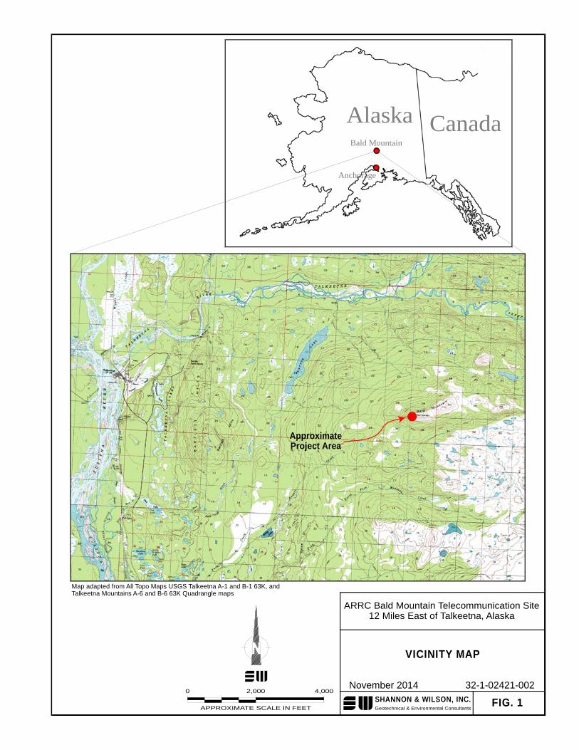
The proposed telecommunications site is situated on the west end of Bald Mountain
approximately 12 miles east of Talkeetna, Alaska. According to the USGS Talkeetna Mountains
B-6 63K Quadrangle map, this project is located in the southwest 1/4, Section 25, Township 26
North, Range 3 West, Seward Meridian. The site is sparsely vegetated with moss and lichen and
the ground surface is generally covered with a rocky rubble typically made up of cobble and
small boulder-sized particles. A primitive airstrip runs in an east-west direction along the
mountaintop south and east of the proposed site. Access to the site was only available via
helicopter, small fixed wing aircraft, or on foot (local trails may provide access via all-terrain
vehicle). A vicinity map depicting the general project area is included as Figure 1.
At the time of our visit the site was developed with an existing communications tower and two
sheds containing support equipment. The existing communications tower consists of an
approximately 20 to 25-foot tall, four legged, tower structure. The existing tower appears to be
resting on steel grade beams that are resting on the ground surface and appears to be attached to
an adjacent connex shed. Rocks have been piled on the beams and two guy wires are attached to
the tower and a deadman anchor (a section of a triangular lattice structure with rocks piled
ARRC Bald Mountain Telecommunication Site, Talkeetna Area, Alaska 32-1-02421-002
2
around it) on the north side of the tower. Another existing communications facility is also
located on the mountaintop several hundred feet east of the ARRC site.
We understand that the project generally consists of the construction of a 30-foot tall, self-
supported, four legged tower (Microflect D4-30) that will likely be supported on a shallow
concrete foundation. The project will also incorporate other hardware that includes an
equipment shelter (which is already on-site), propane tanks, and other appurtenances. According
to available drawings, the tower has a square footprint with approximately 12-foot spacing
between each support leg. Ultimately, the foundations of the towers and other improvements
will need to be designed to resist relatively significant overturning, shear, and vertical forces
(tension and compression).
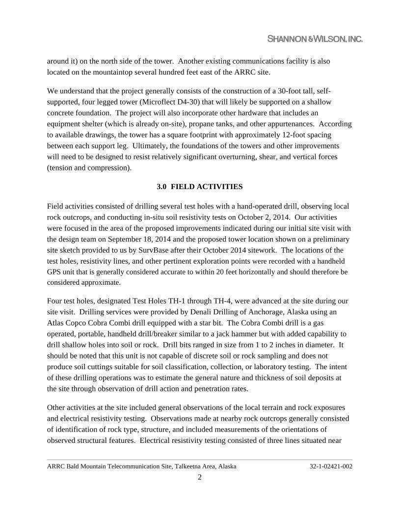
3.0 FIELD ACTIVITIES
Field activities consisted of drilling several test holes with a hand-operated drill, observing local
rock outcrops, and conducting in-situ soil resistivity tests on October 2, 2014. Our activities
were focused in the area of the proposed improvements indicated during our initial site visit with
the design team on September 18, 2014 and the proposed tower location shown on a preliminary
site sketch provided to us by SurvBase after their October 2014 sitework. The locations of the
test holes, resistivity lines, and other pertinent exploration points were recorded with a handheld
GPS unit that is generally considered accurate to within 20 feet horizontally and should therefore be
considered approximate.
Four test holes, designated Test Holes TH-1 through TH-4, were advanced at the site during our
site visit. Drilling services were provided by Denali Drilling of Anchorage, Alaska using an
Atlas Copco Cobra Combi drill equipped with a star bit. The Cobra Combi drill is a gas
operated, portable, handheld drill/breaker similar to a jack hammer but with added capability to
drill shallow holes into soil or rock. Drill bits ranged in size from 1 to 2 inches in diameter. It
should be noted that this unit is not capable of discrete soil or rock sampling and does not
produce soil cuttings suitable for soil classification, collection, or laboratory testing. The intent
of these drilling operations was to estimate the general nature and thickness of soil deposits at
the site through observation of drill action and penetration rates.
Other activities at the site included general observations of the local terrain and rock exposures
and electrical resistivity testing. Observations made at nearby rock outcrops generally consisted
of identification of rock type, structure, and included measurements of the orientations of
observed structural features. Electrical resistivity testing consisted of three lines situated near
ARRC Bald Mountain Telecommunication Site, Talkeetna Area, Alaska 32-1-02421-002
3
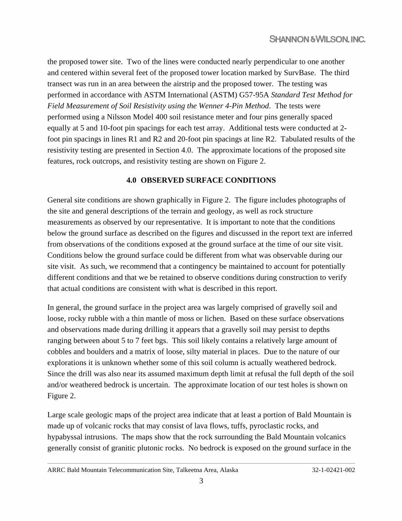
the proposed tower site. Two of the lines were conducted nearly perpendicular to one another
and centered within several feet of the proposed tower location marked by SurvBase. The third
transect was run in an area between the airstrip and the proposed tower. The testing was
performed in accordance with ASTM International (ASTM) G57-95A Standard Test Method for
Field Measurement of Soil Resistivity using the Wenner 4-Pin Method. The tests were
performed using a Nilsson Model 400 soil resistance meter and four pins generally spaced
equally at 5 and 10-foot pin spacings for each test array. Additional tests were conducted at 2-
foot pin spacings in lines R1 and R2 and 20-foot pin spacings at line R2. Tabulated results of the
resistivity testing are presented in Section 4.0. The approximate locations of the proposed site
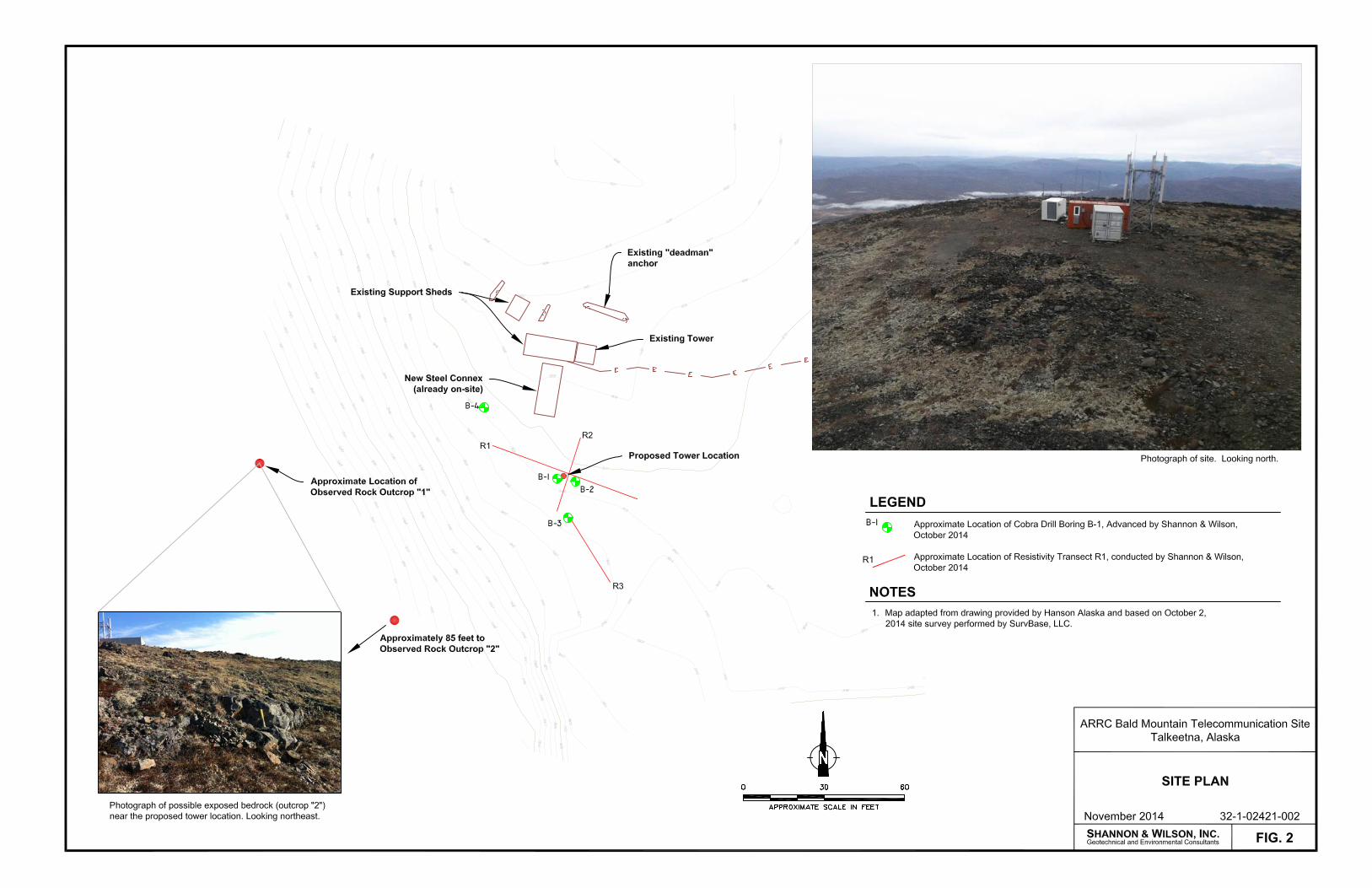
features, rock outcrops, and resistivity testing are shown on Figure 2.
4.0 OBSERVED SURFACE CONDITIONS
General site conditions are shown graphically in Figure 2. The figure includes photographs of
the site and general descriptions of the terrain and geology, as well as rock structure
measurements as observed by our representative. It is important to note that the conditions
below the ground surface as described on the figures and discussed in the report text are inferred
from observations of the conditions exposed at the ground surface at the time of our site visit.
Conditions below the ground surface could be different from what was observable during our
site visit. As such, we recommend that a contingency be maintained to account for potentially
different conditions and that we be retained to observe conditions during construction to verify
that actual conditions are consistent with what is described in this report.
In general, the ground surface in the project area was largely comprised of gravelly soil and
loose, rocky rubble with a thin mantle of moss or lichen. Based on these surface observations
and observations made during drilling it appears that a gravelly soil may persist to depths
ranging between about 5 to 7 feet bgs. This soil likely contains a relatively large amount of
cobbles and boulders and a matrix of loose, silty material in places. Due to the nature of our
explorations it is unknown whether some of this soil column is actually weathered bedrock.
Since the drill was also near its assumed maximum depth limit at refusal the full depth of the soil
and/or weathered bedrock is uncertain. The approximate location of our test holes is shown on
Figure 2.
Large scale geologic maps of the project area indicate that at least a portion of Bald Mountain is
made up of volcanic rocks that may consist of lava flows, tuffs, pyroclastic rocks, and
hypabyssal intrusions. The maps show that the rock surrounding the Bald Mountain volcanics
generally consist of granitic plutonic rocks. No bedrock is exposed on the ground surface in the
ARRC Bald Mountain Telecommunication Site, Talkeetna Area, Alaska 32-1-02421-002
4
immediate project area and bedrock exposures at the site were limited to relatively small
outcrops on the west slope of Bald Mountain below the proposed tower site. Larger outcrops
were visible from the air on the south facing slope of Bald Mountain. Based on visual
classification of rock fragments collected from the ground surface most of the rock rubble on top
of Bald Mountain in the project area appears to consist of a gray to dark gray, fine-grained rock
that may be basalt. Several granitic boulders were also observed on the ground surface near the
existing tower site. Outcrop 1 was located approximately 160 feet southwest of the proposed
new tower site. The rock visible at the outcrop generally appeared to match what may be
basaltic rock observed in the mountaintop rubble. In general the rock appeared relatively
massive with randomly oriented fractures spaced 1 to 2 feet apart. Other outcrops were
observable further southwest and downhill from the tower site. Rock in these outcrops consisted
of a relatively massive, black, crystalline, intrusive igneous rock. Outcrop 2, shown on Figure 2,
shows the location of one of these igneous outcrops. Two primary joint sets were observable at
Outcrop 2. One set dips at about 70 degrees to the northwest (typical measured dip direction of
310º). Joint spacings on the order of 18 inches to greater than 8 feet were estimated based on our
observations of Outcrop 2. The second joint set dips toward the south (typical measured dip
direction of 90º) at an angle of about 15 degrees. Exposures of this second joint set were limited
and we estimated joint spacing in this set was greater than about 4 feet. In general, the rock
observed in the outcrops appeared to be relatively resistive to weathering; however the “rubbly”
appearance of the ground surface may indicate that the rock is somewhat susceptible to
mechanical and/or chemical breakdown.
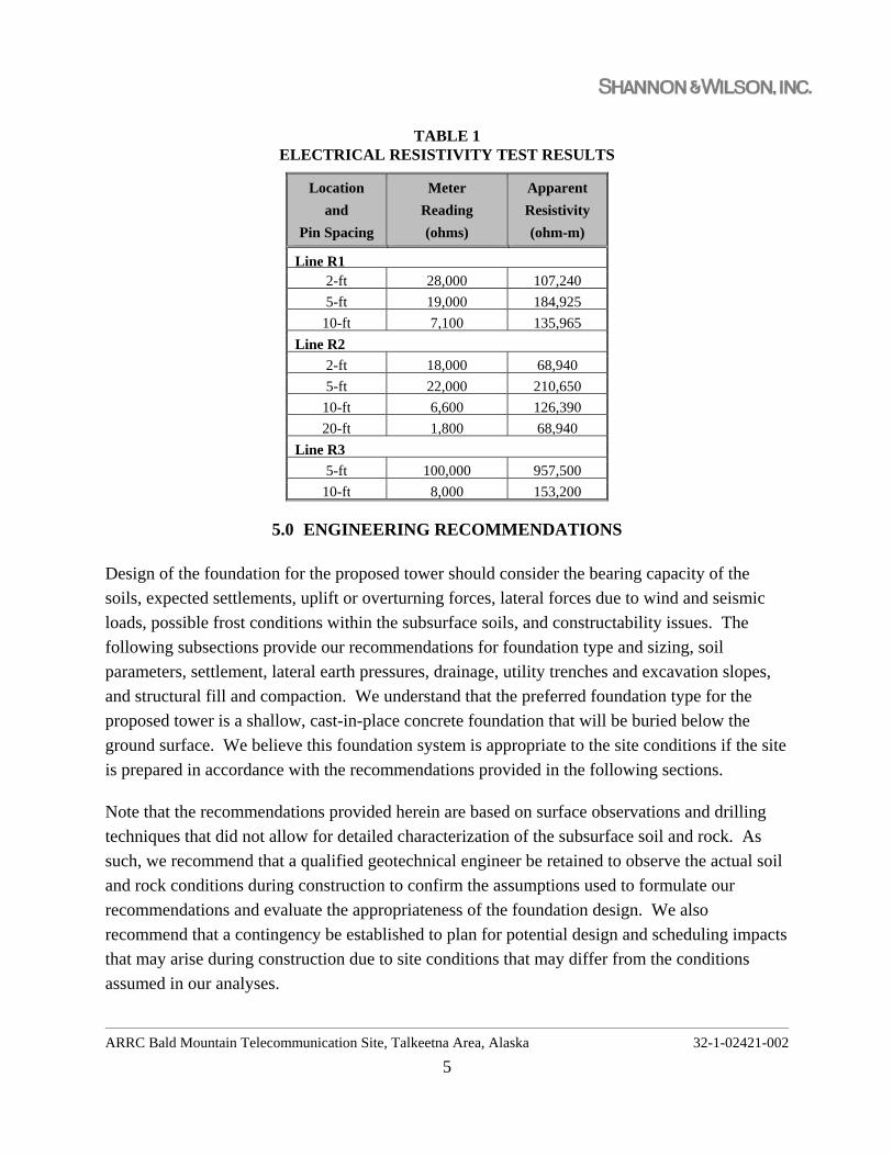
Electrical resistivity testing was conducted during our site visit. The locations of the three test
transects are indicated on Figure 2. The estimated results are summarized in Table 1 below.
ARRC Bald Mountain Telecommunication Site, Talkeetna Area, Alaska 32-1-02421-002
5
TABLE 1 ELECTRICAL RESISTIVITY TEST RESULTS
Location
and
Pin Spacing
Meter
Reading
(ohms)
Apparent
Resistivity
(ohm-m)
Line R1 2-ft 28,000 107,240
5-ft 19,000 184,925
10-ft 7,100 135,965
Line R2
2-ft 18,000 68,940
5-ft 22,000 210,650
10-ft 6,600 126,390
20-ft 1,800 68,940
Line R3
5-ft 100,000 957,500
10-ft 8,000 153,200
5.0 ENGINEERING RECOMMENDATIONS
Design of the foundation for the proposed tower should consider the bearing capacity of the
soils, expected settlements, uplift or overturning forces, lateral forces due to wind and seismic
loads, possible frost conditions within the subsurface soils, and constructability issues. The
following subsections provide our recommendations for foundation type and sizing, soil
parameters, settlement, lateral earth pressures, drainage, utility trenches and excavation slopes,
and structural fill and compaction. We understand that the preferred foundation type for the
proposed tower is a shallow, cast-in-place concrete foundation that will be buried below the
ground surface. We believe this foundation system is appropriate to the site conditions if the site
is prepared in accordance with the recommendations provided in the following sections.
Note that the recommendations provided herein are based on surface observations and drilling
techniques that did not allow for detailed characterization of the subsurface soil and rock. As
such, we recommend that a qualified geotechnical engineer be retained to observe the actual soil
and rock conditions during construction to confirm the assumptions used to formulate our
recommendations and evaluate the appropriateness of the foundation design. We also
recommend that a contingency be established to plan for potential design and scheduling impacts
that may arise during construction due to site conditions that may differ from the conditions
assumed in our analyses.
ARRC Bald Mountain Telecommunication Site, Talkeetna Area, Alaska 32-1-02421-002
6
5.1 Structure Foundations
Based on our limited drilling and surface observations it appears that there is at least 5 to 7 feet
of gravelly soil or rubble, some of which may be weathered bedrock, in the area of the proposed
improvements. It is our opinion that these materials, below about 2 to 3 feet, will provide
adequate support for the proposed tower. At the time of this report, we understand that the
preferred foundation is a shallow concrete foundation that may consist of individual elements at
each tower leg or a cast-in-place concrete pad with pedestals. We believe this foundation system
is appropriate to the site conditions. We recommend that the foundation bear on undisturbed
native soils or on compacted structural fill as detailed herein. Uplift loads would appear to
control the size and depth of the foundation (i.e., a foundation sized to resist uplift and
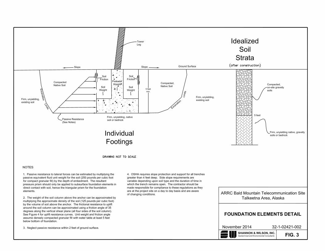
overturning loads should likewise be sufficient to resist the applied downward loads). Figure 8
presents typical foundation element details for a pedestal resting on a buried concrete block.
Excavation in the native soils beyond several feet below the ground surface may be difficult
given the coarse, angular nature of the rocky materials. It is likely that excavations will require
mechanical earthmoving equipment to complete. In preparing the bottom of excavation for
foundation elements, we recommend working the material such that it is as flat as practicable
with hand and mechanical equipment and compacting to a firm state with vibratory equipment.
The surface should be firm, relatively uniform, not contain voids more than approximately 6
inches in diameter, and not able to deflect under compaction equipment. If additional fill is
needed to fill surface voids or level the excavation surface, we recommend importing Selected
Material Type A or B. Placement and compaction recommendations are provided in Section 5.9.
5.2 Foundation Embedment and Frost Considerations
Based on our experience, seasonal frost in the project vicinity may extend to depths of 10 to 12
feet below the ground surface. The native soil materials observed at the site generally consisted
of boulder rubble or cobbles surrounded by a silty sand matrix. In our opinion, these materials
will provide adequate frost protection beneath and around the tower foundation given the
assumed large percentage of gravels/cobbles and the lack of available ground moisture, provided
the proper drainage is maintained around foundation elements. Minor seasonal deflections may
be experienced depending on the actual soil conditions encountered. We assume that it would be
preferable to utilize onsite soils for structural backfill at the site. Prior to reuse we recommend
that the gradation of the materials be confirmed for conformance to the material properties
ARRC Bald Mountain Telecommunication Site, Talkeetna Area, Alaska 32-1-02421-002
7
assumed in our analyses. In general, a gravelly soil with less than about 10 to 15 percent fines
should be appropriate.
If conditions prevent excavation for the minimum recommended embedment below the ground
surface recommended in Section 5.4, additional fill can be placed above the foundation to
effectively raise the elevation of the ground surface around the tower. The fill may be salvaged
from the ground surface on site and placed as recommended in Section 5.9. We recommend
limiting the amount of fill that can be added to no more than 2 feet above the ground surface.
The fill section should cover the entire tower footprint and should extend beyond the footprint of
the foundation a minimum of 10 feet in all directions. Fill should not be removed from the
ground surface from any areas within 25 feet of the proposed tower or any other existing site
features.
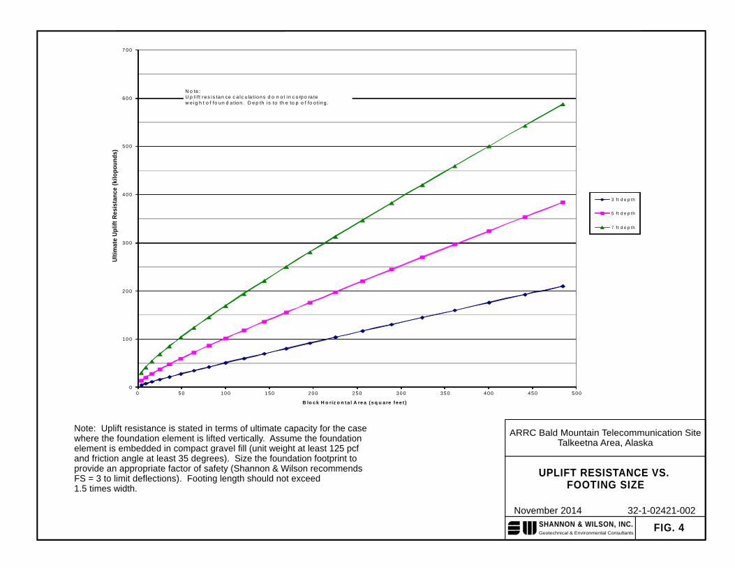
5.3 Uplift Resistance
In our experience, uplift loads generally control the size and depth of the foundation (i.e., a
foundation sized to resist uplift and overturning loads should likewise be sufficient to resist the
applied tower loads). Figure 3 presents typical foundation element details for a four-legged
tower resting on a shallow concrete foundation. The uplift resistance of the foundation can be
estimated by summing the dead weight of the footing, the weight of the soil within a zone
described by a vertical surface extending upward from the horizontal limits of the footing, and
the shearing resistance of the soil across this surface. Additional resistance gained from friction
between the foundation and embedment soils should be negligible in comparison, and in our
opinion should not be used in estimating uplift resistance for the foundations. Assuming a
gravelly soil with less than about 10 to 15 percent fines is used to backfill around and above the
footing using the placement and compaction requirements outlined in Section 5.9, the density of
the soil resisting uplift should be at approximately 125 pounds per cubic foot (pcf). Lastly,
shearing resistance can be calculated using a frictional resistance of about 35 degrees for densely
compacted gravel materials. Using these parameters, we created a graph representing ultimate
uplift resistance shown on Figure 8. This graph represents the calculated ultimate (no factor of
safety included) uplift resistance over a range of footing area and foundation depths, but does not
include the weight of the footing in the calculation.
5.4 Bearing Capacity
After sizing the footing, the foundation should be checked for allowable bearing pressure. We
recommend that the footing be designed using an allowable bearing capacity of 4,500 pounds per
ARRC Bald Mountain Telecommunication Site, Talkeetna Area, Alaska 32-1-02421-002
8
square foot (psf) for a footing embedded a minimum of 5 feet bgs and bearing on compacted
structural fill or native soils. This bearing value may be increased by 1/3 for short-term wind
and seismic loading. Before constructing forms for the footings, we recommend that a qualified
geotechnical engineer be retained to probe the bottom of the excavation to look for loose or
disturbed zones beneath the foundation. If disturbed or loosened soils are encountered by
probing, they should be replaced and re-compacted to a dense state.
Moments created by the structure may create eccentric loads on the foundation element. We
recommend using an effective footing width calculated by subtracting two times the eccentricity
in each direction, in calculations for allowable loading. The above bearing capacity is applicable
only if the eccentricity is less than 1/6 the width of the foundation element. If the eccentricity
exceeds 1/6 the foundation width, we recommend increasing the footing width until the
eccentricity criteria is met. If this is not economically feasible, more complex analysis of
bearing capacity may be required.
5.5 Foundation Settlements
The magnitudes of the settlements that will develop at the communications tower foundation are
dependent upon the applied loads, the density of the support material, and the care with which
structural fills are placed and compacted. Compaction recommendations and procedures
described in Section 5.9 should be strictly followed. We estimate that total maximum
settlements will be about 1 inch or less with differential settlements being about 1/2 of the total
settlements over the width of the footing. The greatest amount of settlement should occur during
construction, essentially as fast as the loads are applied, such that long term settlements should
be relatively small and well within tolerable limits.
5.6 Lateral Earth Pressures
Foundation structures below the ground surface should be designed to resist horizontal earth
pressures. The magnitude of the pressure is dependent on the method of backfill placement, the
type of backfill material, drainage provisions, and whether the vertical structure is permitted to
deflect after or during placement of backfill.
If the structure is allowed to deflect laterally or rotate an amount equal to about 0.001 times the
height of the structure, an active earth pressure condition under static loading would prevail and
an ultimate equivalent fluid weight of 34 pcf is recommended for design of vertical structures.
For rigid structures that are restrained from deflecting at the top, an at-rest earth pressure
condition would prevail and an equivalent fluid weight of 53 pcf is recommended. To simulate
ARRC Bald Mountain Telecommunication Site, Talkeetna Area, Alaska 32-1-02421-002
9
seismic loading (from soils adjacent to the foundation) a rectangular pressure prism with a
magnitude of 13 psf per foot of height should be applied to the footing. Note that these values
reflect free-draining, compact, granular backfill and no hydrostatic forces acting on the structure.
Lateral forces from wind or seismic loading may be resisted by passive earth pressures against
the sides of footings. These resisting pressures can be estimated using an equivalent fluid weight
of 250 pcf. This value includes a factor of safety of at least 1.5 on the full passive earth pressure.
Along with this value, it is also recommended that backfill around the footings be compacted per
Section 5.9.
Lateral resistance may also be developed in friction against sliding along the base of the
foundation placed on grade. These forces may be computed using a friction coefficient of 0.4
between concrete and soil.
5.7 Drainage
Groundwater is not expected it to be encountered during construction activities. However, there
is the potential for surface runoff to infiltrate open excavations during construction. Therefore,
the contractor should be responsible for maintaining site grade to prevent surface water from
entering excavations during periods of high rain or snow melting. The contractor should be
prepared to dewater the excavation with sumps and pumps during construction as needed to
remove water that collects in the excavation.
We recommend that the area around the tower be contoured to provide positive surface drainage
away from the structure and off the site. Contouring the site for positive drainage should
minimize ponding of surface waters during periods of rainfall or rapid snow melting. This in
turn will limit moisture contents in the site soils, which should reduce the potential for frost
wedging.
5.8 Excavation Slopes and Utility Trenches
An excavation will be needed to construct the tower foundation and buried cables may be needed
to tie the new tower into support facilities. Excavations for utilities and tower foundations
should extend down to expose firm, consistent, native mineral soils. The bedding and structural
fill material around utility lines and the foundation should be densely compacted to support and
hold them firmly in place. Soil slopes in these materials will tend to stand steeply initially, but
as they dry they will soften and slump in time to their natural angle of repose, which for planning
purposes is estimated at about 1.5 horizontal to 1 vertical. If excavations are allowed to stay
ARRC Bald Mountain Telecommunication Site, Talkeetna Area, Alaska 32-1-02421-002
10
open to inclement weather, the soil slopes could slough to shallower angles. The slope and
excavation bottom conditions should be made the responsibility of the contractor who will be
present on a day to day basis and can adjust efforts to obtain the needed stability, and meet the
applicable Alaska and Federal (OSHA) safety regulations.
Backfill for the foundation excavations should consist of compacted structural fill as described in
Section 5.9. Above the bedding in underground utilities, excavated native, granular soils should
be used to backfill the trenches, to the extent practicable, up to the original ground surface.
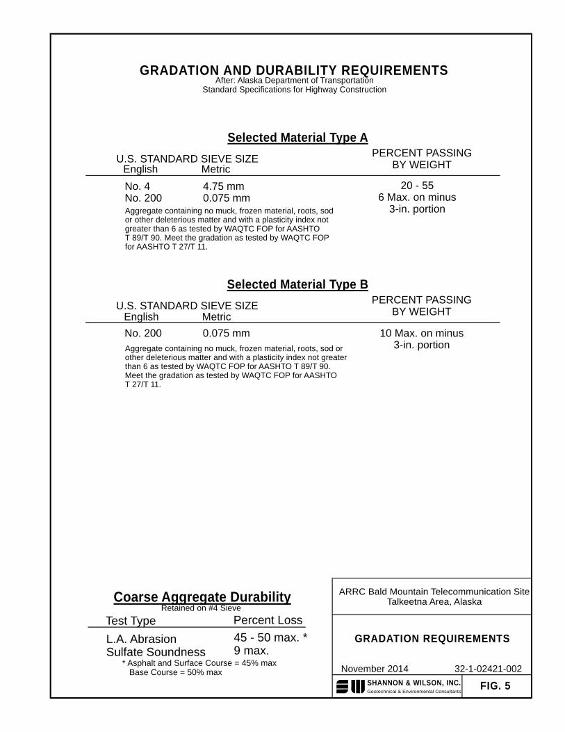
5.9 Structural Fill
Backfill will be required under and around the tower foundation. We anticipate that the existing
soils will consist of sand, gravel, and cobbles with about 10 to 15 percent fines. Minor amounts
of soil fills may need to be imported into the site for bedding cables or levelling foundation pads
and it should consist of clean, granular soil free of organic material to provide drainage and frost
protection. Selected Material Type A or B as Alaska Department of Transportation & Public
Facilities meets these requirements. Gradation requirements for Type II/IIA structural fill are
provided in Figure 5.
The existing native soils observed are expected to be predominantly granular but may not meet
the gradation requirements for Selected Material Type A or B structural fill, as shown on Figure
5. Existing soils that contain more than about 10 to 15 percent fines should not be used as
structural fill below or around foundation elements but may be used as unclassified fill to
contour the site or as utility trench backfill under areas that will not support structures. Likewise,
materials that contain organic or deleterious matter should not be used in structural applications.
Selected Material Types A and B placed as backfill around, above, and below foundation
elements or around buried utilities should be placed in lifts not to exceed 10 to 12 inches loose
thickness and compacted to 95 percent of the maximum density as determined by the Modified
Proctor compaction procedure (ASTM D 1557). During fill placement, we recommend that
large cobbles or boulders with dimensions in excess of 8 inches be removed. Because of the
coarse nature of the existing fills it will be difficult to use moisture/density control to compact
these materials. As such, we recommend using subjective compaction criteria such that
vibratory equipment is used to compact the materials to a visually firm, consistent state where
the fill surface contains minimal voids and does not deflect under compaction equipment
loading.
ARRC Bald Mountain Telecommunication Site, Talkeetna Area, Alaska 32-1-02421-002
11
Bulking of backfill into the excavations should be discouraged as this can cause voids and lead
to large future surface settlements. To avoid damage to foundation elements, fill material within
18 inches of the pedestal and/or block foundation should be placed in layers not to exceed six
inches loose thickness and compacted with hand operated equipment. Heavy equipment should
not be used as it could cause increased lateral pressures and possibly damage the structure.
6.0 CLOSURE/LIMITATIONS
This report was prepared for the exclusive use of our client and their representatives for
evaluating the site as it relates to the geotechnical aspects discussed herein. The conclusions and
recommendations contained in this report are based on information provided from the observed
site conditions and other conditions described herein. The analyses, conclusions and
recommendations contained in this report are based on site conditions as they presently exist. It
is assumed that the observed surface soil and rock conditions are representative of the subsurface
conditions throughout the site, i.e., the subsurface conditions everywhere are not significantly
different from those disclosed by the explorations.
If, during construction, conditions different from those encountered in these explorations are
observed or appear to be present, Shannon & Wilson, Inc. should be advised at once so that these
conditions can be reviewed and recommendations can be reconsidered where necessary. If there
is a substantial lapse of time between the submittal of this report and the start of work at the site,
or if conditions have changed due to natural causes or construction operations at or adjacent to
the site, it is recommended that this report be reviewed to determine the applicability of the
conclusions and recommendations considering the changed conditions and time lapse.
We recommend that we be retained to review those portions of the plans and specifications
pertaining to earthwork and foundations to determine if they are consistent with our
recommendations.
Unanticipated soil conditions are commonly encountered and cannot fully be determined by
merely taking soil samples or excavating test pits. Such unexpected conditions frequently
require that additional expenditures be made to attain a properly constructed project. Therefore,
some contingency fund is recommended to accommodate such potential extra costs. Shannon &
Wilson has prepared the attachments in Appendix A Important Information About Your
Geotechnical/Environmental Report to assist you and others in understanding the use and
limitations of the reports.
ARRC Bald Mountain Telecommunication Site12 Miles East of Talkeetna, Alaska
VICINITY MAP
November 2014
FIG. 1
32-1-02421-002SHANNON & WILSON, INC.Geotechnical & Environmental ConsultantsAPPROXIMATE SCALE IN FEET
0 2,000 4,000
CanadaAlaskaBald Mountain
Anchorage
Map adapted from All Topo Maps USGS Talkeetna A-1 and B-1 63K, and Talkeetna Mountains A-6 and B-6 63K Quadrangle maps
ApproximateProject Area
SHANNON & WILSON, INC.Geotechnical & Environmental Consultants
0
1 0 0
2 0 0
3 0 0
4 0 0
5 0 0
6 0 0
7 0 0
0 5 0 1 0 0 1 5 0 2 0 0 2 5 0 3 0 0 3 5 0 4 0 0 4 5 0 5 0 0
Approximate Uplift Resistance (kips)
B lo c k H o riz o n ta l A re a (s q u a re fe e t )
3 f t d e p th
5 f t d e p th
7 f t d e p th
N o te : U p l i ft r e s i s ta n ce c a l c u la ti o n s d o n o t i n c o rp o ra tew e ig h t o f fo u n d a tio n . D e p th i s to th e to p o f fo o ti n g .
Note: Uplift resistance is stated in terms of ultimate capacity for the case where the foundation element is lifted vertically. Assume the foundation element is embedded in compact gravel fill (unit weight at least 125 pcfand friction angle at least 35 degrees). Size the foundation footprint to provide an appropriate factor of safety (Shannon & Wilson recommends FS = 3 to limit deflections). Footing length should not exceed 1.5 times width.
ARRC Bald Mountain Telecommunication SiteTalkeetna Area, Alaska
UPLIFT RESISTANCE VS. FOOTING SIZE
November 2014
FIG. 4
32-1-02421-002
Ult
imat
e U
plif
t R
esis
tan
ce (
kilo
po
un
ds)
GRADATION AND DURABILITY REQUIREMENTSAfter: Alaska Department of Transportation
Standard Specifications for Highway Construction
Coarse Aggregate Durability
L.A. AbrasionSulfate Soundness
45 - 50 max. *9 max.
Test Type Percent LossRetained on #4 Sieve
* Asphalt and Surface Course = 45% max Base Course = 50% max
Selected Material Type APERCENT PASSING
BY WEIGHTU.S. STANDARD SIEVE SIZE
No. 4No. 200
4.75 mm0.075 mm
Selected Material Type BPERCENT PASSING
BY WEIGHTU.S. STANDARD SIEVE SIZE
No. 200 0.075 mm 10 Max. on minus3-in. portion
20 - 556 Max. on minus
3-in. portion
English Metric
English Metric
SHANNON & WILSON, INC.Geotechnical & Environmental Consultants
ARRC Bald Mountain Telecommunication SiteTalkeetna Area, Alaska
GRADATION REQUIREMENTS
November 2014
FIG. 5
32-1-02421-002
Aggregate containing no muck, frozen material, roots, sodor other deleterious matter and with a plasticity index notgreater than 6 as tested by WAQTC FOP for AASHTOT 89/T 90. Meet the gradation as tested by WAQTC FOPfor AASHTO T 27/T 11.
Aggregate containing no muck, frozen material, roots, sod orother deleterious matter and with a plasticity index not greaterthan 6 as tested by WAQTC FOP for AASHTO T 89/T 90.Meet the gradation as tested by WAQTC FOP for AASHTOT 27/T 11.
32-1-02421-002
APPENDIX A
IMPORTANT INFORMATION ABOUT YOUR GEOTECHNICAL/ENVIRONMENTAL REPORT
Page 1 of 2 3/2004
SHANNON & WILSON, INC. Geotechnical and Environmental Consultants
Attachment to 32-1-02421-002 Date: November 2014 To: Hanson Alaska Re: ARRC Bald Mountain Telecommunication
Site, Talkeetna Area, Alaska
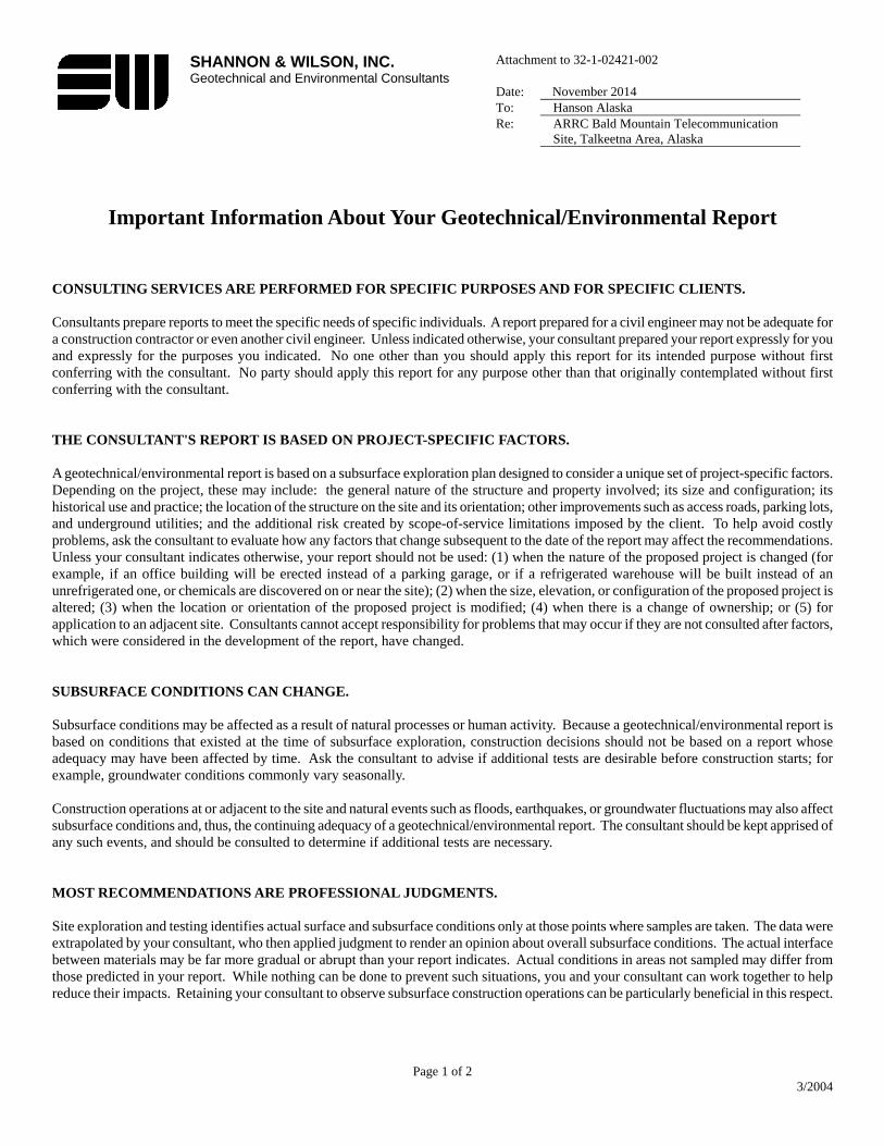
Important Information About Your Geotechnical/Environmental Report CONSULTING SERVICES ARE PERFORMED FOR SPECIFIC PURPOSES AND FOR SPECIFIC CLIENTS. Consultants prepare reports to meet the specific needs of specific individuals. A report prepared for a civil engineer may not be adequate for a construction contractor or even another civil engineer. Unless indicated otherwise, your consultant prepared your report expressly for you and expressly for the purposes you indicated. No one other than you should apply this report for its intended purpose without first conferring with the consultant. No party should apply this report for any purpose other than that originally contemplated without first conferring with the consultant. THE CONSULTANT'S REPORT IS BASED ON PROJECT-SPECIFIC FACTORS. A geotechnical/environmental report is based on a subsurface exploration plan designed to consider a unique set of project-specific factors. Depending on the project, these may include: the general nature of the structure and property involved; its size and configuration; its historical use and practice; the location of the structure on the site and its orientation; other improvements such as access roads, parking lots, and underground utilities; and the additional risk created by scope-of-service limitations imposed by the client. To help avoid costly problems, ask the consultant to evaluate how any factors that change subsequent to the date of the report may affect the recommendations. Unless your consultant indicates otherwise, your report should not be used: (1) when the nature of the proposed project is changed (for example, if an office building will be erected instead of a parking garage, or if a refrigerated warehouse will be built instead of an unrefrigerated one, or chemicals are discovered on or near the site); (2) when the size, elevation, or configuration of the proposed project is altered; (3) when the location or orientation of the proposed project is modified; (4) when there is a change of ownership; or (5) for application to an adjacent site. Consultants cannot accept responsibility for problems that may occur if they are not consulted after factors, which were considered in the development of the report, have changed. SUBSURFACE CONDITIONS CAN CHANGE. Subsurface conditions may be affected as a result of natural processes or human activity. Because a geotechnical/environmental report is based on conditions that existed at the time of subsurface exploration, construction decisions should not be based on a report whose adequacy may have been affected by time. Ask the consultant to advise if additional tests are desirable before construction starts; for example, groundwater conditions commonly vary seasonally. Construction operations at or adjacent to the site and natural events such as floods, earthquakes, or groundwater fluctuations may also affect subsurface conditions and, thus, the continuing adequacy of a geotechnical/environmental report. The consultant should be kept apprised of any such events, and should be consulted to determine if additional tests are necessary. MOST RECOMMENDATIONS ARE PROFESSIONAL JUDGMENTS. Site exploration and testing identifies actual surface and subsurface conditions only at those points where samples are taken. The data were extrapolated by your consultant, who then applied judgment to render an opinion about overall subsurface conditions. The actual interface between materials may be far more gradual or abrupt than your report indicates. Actual conditions in areas not sampled may differ from those predicted in your report. While nothing can be done to prevent such situations, you and your consultant can work together to help reduce their impacts. Retaining your consultant to observe subsurface construction operations can be particularly beneficial in this respect.
Page 2 of 2 3/2004
A REPORT'S CONCLUSIONS ARE PRELIMINARY. The conclusions contained in your consultant's report are preliminary because they must be based on the assumption that conditions revealed through selective exploratory sampling are indicative of actual conditions throughout a site. Actual subsurface conditions can be discerned only during earthwork; therefore, you should retain your consultant to observe actual conditions and to provide conclusions. Only the consultant who prepared the report is fully familiar with the background information needed to determine whether or not the report's recommendations based on those conclusions are valid and whether or not the contractor is abiding by applicable recommendations. The consultant who developed your report cannot assume responsibility or liability for the adequacy of the report's recommendations if another party is retained to observe construction. THE CONSULTANT'S REPORT IS SUBJECT TO MISINTERPRETATION. Costly problems can occur when other design professionals develop their plans based on misinterpretation of a geotechnical/environmental report. To help avoid these problems, the consultant should be retained to work with other project design professionals to explain relevant geotechnical, geological, hydrogeological, and environmental findings, and to review the adequacy of their plans and specifications relative to these issues. BORING LOGS AND/OR MONITORING WELL DATA SHOULD NOT BE SEPARATED FROM THE REPORT. Final boring logs developed by the consultant are based upon interpretation of field logs (assembled by site personnel), field test results, and laboratory and/or office evaluation of field samples and data. Only final boring logs and data are customarily included in geotechnical/environmental reports. These final logs should not, under any circumstances, be redrawn for inclusion in architectural or other design drawings, because drafters may commit errors or omissions in the transfer process. To reduce the likelihood of boring log or monitoring well misinterpretation, contractors should be given ready access to the complete geotechnical engineering/environmental report prepared or authorized for their use. If access is provided only to the report prepared for you, you should advise contractors of the report's limitations, assuming that a contractor was not one of the specific persons for whom the report was prepared, and that developing construction cost estimates was not one of the specific purposes for which it was prepared. While a contractor may gain important knowledge from a report prepared for another party, the contractor should discuss the report with your consultant and perform the additional or alternative work believed necessary to obtain the data specifically appropriate for construction cost estimating purposes. Some clients hold the mistaken impression that simply disclaiming responsibility for the accuracy of subsurface information always insulates them from attendant liability. Providing the best available information to contractors helps prevent costly construction problems and the adversarial attitudes that aggravate them to a disproportionate scale. READ RESPONSIBILITY CLAUSES CLOSELY. Because geotechnical/environmental engineering is based extensively on judgment and opinion, it is far less exact than other design disciplines. This situation has resulted in wholly unwarranted claims being lodged against consultants. To help prevent this problem, consultants have developed a number of clauses for use in their contracts, reports and other documents. These responsibility clauses are not exculpatory clauses designed to transfer the consultant's liabilities to other parties; rather, they are definitive clauses that identify where the consultant's responsibilities begin and end. Their use helps all parties involved recognize their individual responsibilities and take appropriate action. Some of these definitive clauses are likely to appear in your report, and you are encouraged to read them closely. Your consultant will be pleased to give full and frank answers to your questions.
The preceding paragraphs are based on information provided by the ASFE/Association of Engineering Firms Practicing in the Geosciences, Silver Spring, Maryland