geotechnical exploration report orange county … · geotechnical exploration report . orange...
TRANSCRIPT
GEOTECHNICAL EXPLORATION REPORT ORANGE COUNTY WATER DISTRICT
MID-BASIN INJECTION WELLS PROJECT AT CENTENNIAL PARK
CITY OF SANTA ANA, CALIFORNIA
Prepared for:
TETRA TECH, INC. 17885 Von Karman Avenue, Suite 500
Irvine, California 92614
Project No. 11099.001
September 22, 2015 (Revised October 5, 2015)

September 22, 2015 (Revised October 5, 2015)
Project No. 11099.001
Tetra Tech, Inc. 17885 Von Karman Avenue, Suite 500 Irvine, California 92614 Attention: Mr. Tom Epperson, PE Subject: Geotechnical Exploration Report
Orange County Water District Mid-Basin Injection Wells Project at Centennial Park City of Santa Ana, California In accordance with your request, Leighton Consulting, Inc. has performed a geotechnical exploration and analysis as your subconsultant for the proposed Mid-Basin Injection Wells Project at Centennial Park for the Orange County Water District (OCWD). The proposed project includes four below grade vaults for injection wells, two shared structures, new pipelines, and asphalt overlay on the existing roads and parking lots. This report is prepared in accordance with our revised proposal dated May 13, 2015, and information provided by you.
Earth materials encountered during the field exploration consisted of sand with varying amount of silt to a depth of approximately 10 feet. The sand was dry to slightly moist with little cementation. Below approximately 10 feet, the soils consisted mainly of medium dense silt and medium stiff clay. Groundwater was encountered in six of our borings between the depths of 13 and 23 feet.
Geotechnical aspects of the site that should be considered in design and construction include potential for caving sand, shallow groundwater, and strong seismic shaking during design life of the proposed project.
11099.001
2
The proposed project is feasible from a geotechnical standpoint, provided the findings and recommendations presented in this report are incorporated into the design and construction. This report presents the results of our field exploration, laboratory testing, and geotechnical analyses, and provides our recommendations for the proposed project.
We appreciate the opportunity to work with you on this project. If you have any questions, or if we can be of further service, please contact us at your convenience.
Respectfully submitted, LEIGHTON CONSULTING, INC. Djan Chandra, PE, GE 2376 Senior Principal Engineer
LK/DJC/gv Distribution: (1) Addressee

11099.001
i
TABLE OF CONTENTS Section Page 1.0 INTRODUCTION .................................................................................................. 1
1.1 Site Location and Proposed Project ........................................................... 1 1.2 Purpose and Scope of Services ................................................................. 1
2.0 FINDINGS ............................................................................................................ 4
2.1 Geologic Setting ........................................................................................ 4 2.2 Subsurface Conditions ............................................................................... 4 2.3 Groundwater .............................................................................................. 4 2.4 Soil Corrosivity ........................................................................................... 5 2.5 Faulting and Seismicity .............................................................................. 6 2.6 Liquefaction Hazards ................................................................................. 6
3.0 RECOMMENDATIONS ........................................................................................ 8
3.1 Site Grading ............................................................................................... 8
3.1.1 Site Preparation .............................................................................. 8 3.1.2 Overexcavation and Recompaction ................................................ 8 3.1.3 Fill Placement and Compaction....................................................... 9
3.2 Foundation Design Parameters ................................................................. 9
3.2.1 Shared Structures ........................................................................... 9 3.2.2 Below Grade Vaults ...................................................................... 10 3.2.3 Lateral Load Resistance ............................................................... 10
3.3 Slab-On-Grade ........................................................................................ 11 3.4 Lateral Earth Pressures ........................................................................... 12 3.5 Seismic Design Parameters ..................................................................... 13 3.6 Pipeline Trench Subgrade and Backfill .................................................... 13
4.0 CONSTRUCTION CONSIDERATIONS ............................................................. 15
4.1 Open Trench Construction ....................................................................... 15 4.2 Dewatering during Construction ............................................................... 15 4.3 Temporary Shoring .................................................................................. 16 4.4 Restoring Asphalt Paving ......................................................................... 17 4.5 Additional Geotechnical Services ............................................................ 17
5.0 LIMITATIONS ..................................................................................................... 19
11099.001
ii
6.0 REFERENCES ................................................................................................... 20
LIST OF ATTACHMENTS Important Information About Your Geotechnical Engineering Report Rear of Text Figures Figure 1 – Site Location Map Rear of Text Figure 2 – Boring Location Map Rear of Text Appendices Appendix A – Boring Logs Appendix B – Laboratory Test Results

11099.001
1
1.0 INTRODUCTION
1.1 Site Location and Proposed Project
Centennial Park is located east of the Santa Ana River and south of Edinger Avenue in the city of Santa Ana, California. The site location (latitude N33.7254° and W117.9198°) and immediate vicinity is shown on Figure 1, Site Location Map. OCWD plans to construct four groundwater injection wells in below grade vaults within the park. The source of water to these wells will be the Groundwater Replenishment System (GWRS) pipeline located in the western levee of the Santa Ana River. A new supply pipeline of approximately 5,500 feet long, ranging from 36 to 16 inches in diameter, will be installed to supply the water from the GWRS pipeline to the injection wells. The pipeline will cross the Santa Ana River on to Edinger Avenue and, within the park, will generally follow alignment of the existing roads and parking lots. The supply pipeline is expected to be steel and/or ductile iron pipe. A backflush discharge pipeline with a preliminary sizing of 16 inches and length of approximately 4,500 feet will be constructed to discharge to the Greenville-Banning Channel on the eastern edge of Centennial Park. The discharge pipeline is expected to be steel, PVC, and/or ductile iron pipe. The two pipelines will mostly share a joint trench along with power and communication conduits. The project will also include two new shared structures that will house electrical, communication and process control equipment. The structures will be shared with the City and serve as public restroom and changing rooms, and an office space. The proposed utility rooms will be approximately 16 by 16 feet square. A deep, multi-depth nested monitoring well will be constructed south of the park in a property currently occupied by Heritage Museum. Additionally, the majority of parking and roadway area within the park (approximately 9.6 acres) will be cold milled by 2 inches and repaved.
1.2 Purpose and Scope of Services
The purpose of our geotechnical exploration was to evaluate the subsurface conditions and general soil characteristics at the project site in order to provide geotechnical recommendations for design and construction of the project as currently proposed. Since OCWD will design the injection wells and monitoring well in house, the project elements that are part of the scope of services of the

11099.001
2
design team include well vaults, above-well piping, pumping system, and paving improvements. The scope of our exploration included the following tasks:
• Background Review – A background review was performed of readily available, relevant geotechnical and geological literature pertinent to the site; References used in preparation of this report are listed in Section 6.0.
• Pre-Field Exploration Activities – Boring locations were marked and Underground Service Alert (USA) was notified to locate and mark existing underground utilities prior to our subsurface exploration. An encroachment permit was obtained from the City of Santa Ana for drilling within the public right-of-way.
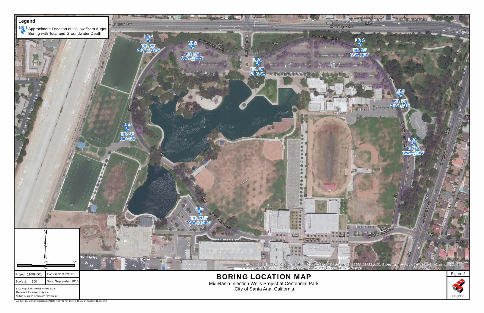
• Field Exploration – We advanced four hollow-stem auger borings (LB-2 , LB-4, LB-6 and LB-7) at the approximate vault locations to a depth of 25 feet, two borings (LB-1 and LB-5) at the shared structure locations to depths of 20 and 25 feet, and two borings (LB-3 and LB-8) within the parks to depth of 10 feet on August 18, 2015. The approximate boring locations performed by Leighton (LB-1 through LB-8) are shown on Figure 2, Boring Location Map and summarized in Table 1.
Table 1 – Boring Summary
Boring No. Total Depth (feet) Location
LB-1 25 Shared Structure
LB-2 25 Injection Well Vault
LB-3 10 Pipeline
LB-4 25 Injection Well Vault
LB-5 20 Shared Structure
LB-6 25 Injection Well Vault
LB-7 25 Injection Well Vault
LB-8 10 Pipeline
The borings were geotechnically logged and sampled using Standard Penetration Test (SPT) and California Ring samplers at selected intervals. The SPT and Ring samplers were driven into the soil with a 140-pound hammer, free falling 30 inches. The number of blows was noted for every 6 inches of sampler penetration. Relatively undisturbed samples were collected

11099.001
3
from the borings using the Ring sampler. The sampling procedures generally followed ASTM Test Method D 1586 and D 3550 for SPT and split-barrel sampling of soil. In addition to driven samples, representative bulk soil samples were also collected from the borings. Each soil sample collected was described in general conformance with the Unified Soil Classification System (USCS). The samples were sealed, packaged, and transported to our soil laboratory. The soil descriptions and depths are noted on the boring logs included in Appendix A, Boring Logs.
• Laboratory Tests – Laboratory tests were performed on selected soil samples obtained during our field investigation. The laboratory testing program was designed to evaluate the physical and engineering characteristics of the onsite soil. Tests performed during this investigation include:
- Moisture Content and Dry Density (ASTM D 2216 and ASTM D 2937);
- Sieve Analysis (ASTM D 6913);
- Consolidation (ASTM D 2435) ;
- Direct Shear (ASTM D 3080);
- Corrosivity Suite – pH, Sulfate, Chloride, and Resistivity (California Test Methods 417, 422, and 643).
- Maximum Density (ASTM D 698); and
- R-Value (California Test Method 301).
Results of moisture content and dry density testing are presented on the boring logs in Appendix A. Other laboratory test results are presented in Appendix B, Laboratory Test Results.
• Engineering Analysis - The data obtained from our background review, field exploration, and laboratory testing program were evaluated and analyzed to develop the recommendations presented in this report for the proposed project.
• Report Preparation - The results of the exploration are summarized in this report presenting our findings, conclusions and recommendations.
11099.001
4
2.0 FINDINGS
2.1 Geologic Setting
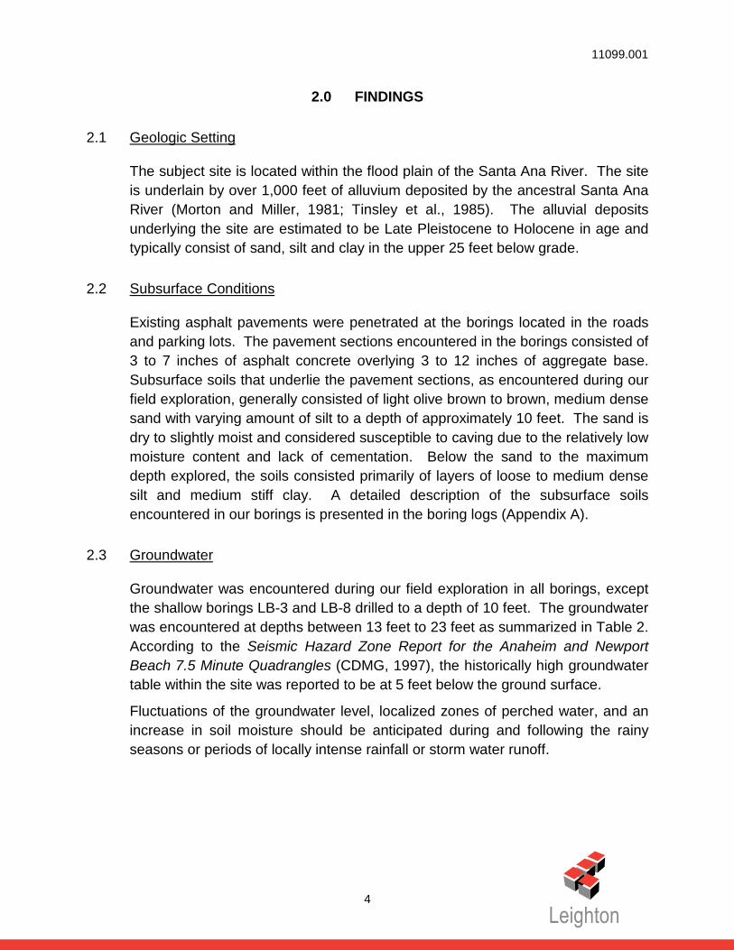
The subject site is located within the flood plain of the Santa Ana River. The site is underlain by over 1,000 feet of alluvium deposited by the ancestral Santa Ana River (Morton and Miller, 1981; Tinsley et al., 1985). The alluvial deposits underlying the site are estimated to be Late Pleistocene to Holocene in age and typically consist of sand, silt and clay in the upper 25 feet below grade.
2.2 Subsurface Conditions
Existing asphalt pavements were penetrated at the borings located in the roads and parking lots. The pavement sections encountered in the borings consisted of 3 to 7 inches of asphalt concrete overlying 3 to 12 inches of aggregate base. Subsurface soils that underlie the pavement sections, as encountered during our field exploration, generally consisted of light olive brown to brown, medium dense sand with varying amount of silt to a depth of approximately 10 feet. The sand is dry to slightly moist and considered susceptible to caving due to the relatively low moisture content and lack of cementation. Below the sand to the maximum depth explored, the soils consisted primarily of layers of loose to medium dense silt and medium stiff clay. A detailed description of the subsurface soils encountered in our borings is presented in the boring logs (Appendix A).
2.3 Groundwater
Groundwater was encountered during our field exploration in all borings, except the shallow borings LB-3 and LB-8 drilled to a depth of 10 feet. The groundwater was encountered at depths between 13 feet to 23 feet as summarized in Table 2. According to the Seismic Hazard Zone Report for the Anaheim and Newport Beach 7.5 Minute Quadrangles (CDMG, 1997), the historically high groundwater table within the site was reported to be at 5 feet below the ground surface.
Fluctuations of the groundwater level, localized zones of perched water, and an increase in soil moisture should be anticipated during and following the rainy seasons or periods of locally intense rainfall or storm water runoff.

11099.001
5
Table 2 – Summary of Groundwater Depths
Boring No. Total Depth (feet) Groundwater Depth (feet)
LB-1 25 18.5
LB-2 25 23
LB-3 10 Not Encountered
LB-4 25 16
LB-5 20 19
LB-6 25 13
LB-7 25 15
LB-8 10 Not Encountered
2.4 Soil Corrosivity
In general, soil environments that are detrimental to concrete have high concentrations of soluble sulfates and/or pH values of less than 5.5. Soils with chloride content greater than 500 ppm per California Test 422 are considered corrosive to steel, either in the form of reinforcement protected by concrete cover or plain steel substructures, such as steel pipes. Additionally, soils with a minimum resistivity of less than 1,000 Ohm-cm are considered corrosive to ferrous metal. Corrosivity test results are included in Appendix B of this report and summarized in Table 3.
Table 3 – Summary of Corrosivity Test Results
Test Parameter Test Results* General Classification of Hazard
Water-soluble sulfate content 153 and 170 ppm
Negligible sulfate exposure to buried concrete (per ACI 318-11)
Water-soluble chloride content 62 and 71 ppm Non-corrosive to buried concrete
(per Caltrans Specifications)
pH 7.99 and 8.14 Slightly to moderately alkaline, relatively passive to buried metals
Minimum resistivity (in saturated condition)
1,695 and 3,250 Ohm-cm
Slightly corrosive to buried ferrous metal pipes
*Borings LB-4 and LB-6

11099.001
6
Based on the laboratory test results, the subsurface soils at the project site exhibit “negligible” potential for sulfate attack on concrete and are considered to have low corrosion potential to buried ferrous metal in direct contact with the soils.
2.5 Faulting and Seismicity
Our review of available in-house literature indicates that there are no known active or potentially active faults traversing the site and the site is not located within a State of California designated Alquist-Priolo Earthquake Fault Zone (Bryant and Hart, 2007). The principal seismic hazard that could affect the site is ground shaking resulting from an earthquake occurring along any one of several major active faults in the region. Known regional active and potentially active faults that could produce significant ground shaking at the site include the San Joaquin Hills Blind Thrust, Newport Inglewood, Puente Hills Blind Thrust, and Elsinore faults located at approximately 2.1, 5.4, 10.1, and 14.4 miles, respectively, from the site.
The intensity of ground shaking at a given location depends primarily upon the earthquake magnitude, the distance from the source, and the site response characteristics. Peak ground accelerations are generally used to evaluate the intensity of ground motion. Using the United States Geological Survey (USGS) Seismic Design Map (USGS, 2013), the peak ground acceleration for the Maximum Considered Earthquake (MCEG) adjusted for the Site Class effects (PGAM) is 0.56g. Based on the USGS online interactive deaggregation program (USGS, 2008), the modal seismic event is Moment Magnitude (MW) 7.0 at a distance of 3.1 miles.
2.6 Liquefaction Hazards
Liquefaction is the loss of soil strength or stiffness due to a buildup of pore-water pressure during severe ground shaking. Liquefaction is associated primarily with loose (low density), saturated, fine-to-medium grained, cohesionless soils. As the shaking action of an earthquake progresses, the soil gains are rearranged and the soil densifies within a short period of time. Rapid pore-water pressure approaches the overburden pressure, the soil reduces greatly in strength and temporarily behaves similarly to a fluid.

11099.001
7
Review of the Seismic Hazard Zone Map for the Newport Beach 7.5 Minute Quadrangle (CDMG, 1997) indicates the subject site is located within an area that has been identified by the State of California as being potentially susceptible to the occurrence of liquefaction. This is primarily due to relatively shallow historically high groundwater level and loose to medium dense sand and silt. Detailed evaluation of the potential for liquefaction to occur and the effect on the proposed project was beyond the scope of this exploration and was not required by the code for non-habitable structures.

11099.001
8
3.0 RECOMMENDATIONS
Presented below are the geotechnical recommendations for design and construction of the project. The recommendations are based upon the exhibited geotechnical engineering properties of the soils and their anticipated response both during and after construction as well as proper field observation and testing during construction. The recommendations are considered minimal and may be superseded by more restrictive requirements of OCWD, City of Santa Ana, and the civil and structural engineers.
3.1 Site Grading
All site grading should be performed in accordance with the applicable local codes and in accordance with the project specifications that are prepared by the appropriate design professional. As a minimum, the earthwork guidelines in the following sections should be followed.
3.1.1 Site Preparation
Prior to construction, the site should be cleared of existing improvements and debris. Existing utility and irrigation lines should be removed or properly protected in place if they interfere with the proposed construction. Abandoned utility trenches or cavities should be excavated to expose competent material before being properly backfilled and compacted under the observation and testing of the geotechnical engineer. Subgrade in areas to receive new fill should be observed by a representative of the geotechnical engineer prior to placement of fill to verify that suitable soils are exposed. Subgrade suitable for fill placement or other improvements, such as pavement and concrete flatwork, should be scarified to a depth of at least 8 inches, moisture-conditioned, and compacted to a minimum relative compaction of 90 percent.
3.1.2 Overexcavation and Recompaction
The proposed shared structures may be supported on a conventional shallow foundation system established on engineered fill. To provide a uniform support and reduce the potential for differential settlement, we recommend that foundations for the proposed buildings be underlain by a minimum 3 feet of compacted fill. The structural fill should extend a minimum 3 feet beyond outside edges of the foundation, where feasible.

11099.001
9
Slab-on-grade for the buildings should be underlain by a minimum 12 inches of compacted fill.
Below grade vaults for the injection wells should be supported on competent subgrade as determined by the geotechnical engineer. Wet and pumping subgrade may be encountered at the excavation bottoms for the vault construction. Such materials, if present, should be removed to a minimum depth of 2 feet and replaced with compacted crushed rock of 1 inch or larger. To provide a uniform support, the vaults should be underlain by a minimum 12 inches of compacted fill, aggregate base or ¾-inch crushed rock. If compacted fill or aggregate base is used, a layer of filter fabric should be placed below this material to separate it from the 1 inch or larger crushed rock used to stabilize wet and pumping soils.
Local conditions may be encountered which may require additional removals and recompaction. The exact extent of removals can best be determined during grading by the geotechnical engineer when direct observation and evaluation of materials are possible
3.1.3 Fill Placement and Compaction
The onsite soils to be used as compacted structural fill should be free of organic material or construction debris. Imported fill soil, if any, should be approved by the geotechnical engineer prior to placement as fill. Fill soils should be placed in loose lifts not exceeding 8 inches, moisture-conditioned as necessary to slightly above optimum moisture content and compacted to a minimum of 90 percent of the maximum dry density as determined by ASTM Test Method D 1557.
3.2 Foundation Design Parameters
3.2.1 Shared Structures
The proposed shared structures may be supported on a shallow foundation system upon completion of the recommended site grading as described in this report. Footings should have a minimum embedment depth of 18 inches and a minimum width of 12 inches. An allowable bearing pressure of 2,500 psf may be used based on the minimum embedment depth and width. The allowable bearing value may be increased by 300 psf per foot increase in depth or width to a maximum

11099.001
10
allowable bearing pressure of 4,000 psf. The allowable bearing pressures are for the total dead load and frequently applied live loads and may be increased by one third when considering loads of short duration, such as those imposed by wind and seismic forces. The allowable bearing pressures are net values; the weight of the footing may be neglected for design purposes.
All continuous footings should be reinforced with top and bottom steel to provide structural continuity and to permit spanning of local irregularities. It is essential that a geotechnical engineer observes footing excavations before reinforcing steel is placed.
The recommended allowable bearing capacity for shallow footings is generally based on a total allowable static settlement of 1 inch. Since settlement is a function of footing size and contact bearing pressure, differential settlement can be expected between adjacent columns or walls where a large differential loading condition exists. The differential settlement should be less than approximately ½ inch, assuming no more than 50 percent variation in dead plus sustained live load between adjacent columns. These settlement estimates should be reviewed by Leighton Consulting when final foundation plans and loads for the proposed structures become available.
3.2.2 Below Grade Vaults
The below grade vaults may be supported on a mat foundation bearing on properly compacted structural fill described in this report. The mat foundation may be designed using a maximum allowable bearing capacity 2,500 psf and a modulus of subgrade reaction of 115 pounds per cubic inch (pci).
Total and differential settlements of the mat foundation due to the static loads are expected to be on the order of 1 inch and ½ over a distance of 30 feet, respectively. The allowable bearing pressures may be increased by one third when considering loads of short duration.
3.2.3 Lateral Load Resistance
Resistance to lateral loads will be provided by a combination of friction between the soils and foundation interface and passive pressure acting

11099.001
11
against the vertical portion of the foundation. A friction coefficient of 0.35 may be used at the soil-concrete interface for calculating the sliding resistance. A passive pressure based on an equivalent fluid pressure of 330 pounds per cubic foot (pcf) may be used for calculating the lateral passive resistance. The lateral passive resistance can be taken into account only if it is ensured that the soils against embedded structures will remain intact with time. The above values do not contain an appreciable factor of safety, so the structural engineer should apply the applicable factors of safety and/or load factors during design.
3.3 Slab-On-Grade
Concrete slabs-on-grade subjected to special loads should be designed by the structural engineer. Where conventional light floor loading conditions exist, the following minimum recommendations for conventional slabs-on-grade should be used. More stringent requirements may be required by local agencies, the structural engineer, the architect, or the CBC.
• A minimum slab thickness of 5 inches. Slab reinforcement should be designed by the structural engineer but as a minimum should consist of No. 3 rebar placed at 24 inches on center in each direction and provided with adequate concrete cover.
• A vapor barrier, 10-mil or thicker, should be placed below slabs where moisture-sensitive floor coverings or equipment is planned. The moisture retarder should be properly sealed at all joints and any penetrations.
• To reduce the potential for excessive cracking, concrete slabs-on-grade should be provided with construction or weakened plane joints at frequent intervals. Joints should be laid out to form approximately square panels.
• The subgrade soil should be wetted prior to placing the vapor barrier, steel, or concrete.
Our experience indicates that use of reinforcement in slabs can generally reduce the potential for drying and shrinkage cracking. Some cracking should be expected as the concrete cures. Minor cracking is considered normal; however, it is often aggravated by a high water/cement ratio, high concrete temperature at the time of placement, small nominal aggregate size, and rapid moisture loss due to hot, dry, and/or windy weather conditions during placement and curing.
11099.001
12
Cracking due to temperature and moisture fluctuations can also be expected. The use of low slump concrete can reduce the potential for shrinkage cracking.
3.4 Lateral Earth Pressures
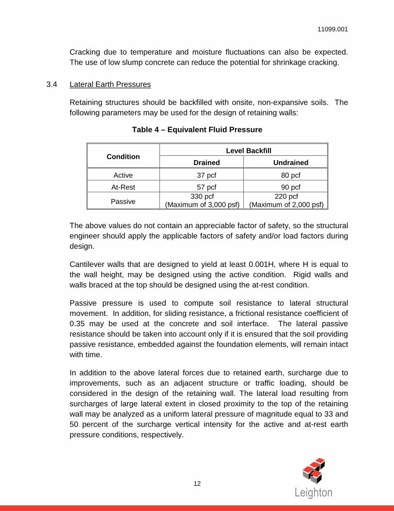
Retaining structures should be backfilled with onsite, non-expansive soils. The following parameters may be used for the design of retaining walls:
Table 4 – Equivalent Fluid Pressure
Condition Level Backfill
Drained Undrained
Active 37 pcf 80 pcf
At-Rest 57 pcf 90 pcf
Passive 330 pcf
(Maximum of 3,000 psf) 220 pcf
(Maximum of 2,000 psf) The above values do not contain an appreciable factor of safety, so the structural engineer should apply the applicable factors of safety and/or load factors during design.
Cantilever walls that are designed to yield at least 0.001H, where H is equal to the wall height, may be designed using the active condition. Rigid walls and walls braced at the top should be designed using the at-rest condition.
Passive pressure is used to compute soil resistance to lateral structural movement. In addition, for sliding resistance, a frictional resistance coefficient of 0.35 may be used at the concrete and soil interface. The lateral passive resistance should be taken into account only if it is ensured that the soil providing passive resistance, embedded against the foundation elements, will remain intact with time.
In addition to the above lateral forces due to retained earth, surcharge due to improvements, such as an adjacent structure or traffic loading, should be considered in the design of the retaining wall. The lateral load resulting from surcharges of large lateral extent in closed proximity to the top of the retaining wall may be analyzed as a uniform lateral pressure of magnitude equal to 33 and 50 percent of the surcharge vertical intensity for the active and at-rest earth pressure conditions, respectively.

11099.001
13
To use the lateral earth pressures for drained condition, design and construction of the walls will require some form of permanent subsurface drainage system behind the wall. If no drainage is provided and for portions of the structure below the groundwater table, the lateral earth pressures for undrained condition should be considered in the wall design.
3.5 Seismic Design Parameters
This site is not located within a currently designated Alquist-Priolo Earthquake Fault Zone. However, strong ground shaking due to seismic activity is anticipated at the sites. To reduce the effects of ground shaking produced by regional seismic events, seismic design should be performed in accordance with the applicable building codes. The following data may be considered for the seismic analysis of the project based on the 2013 CBC.
Table 5 – Seismic Design Parameters
3.6 Pipeline Trench Subgrade and Backfill
The exposed surfaces at the bottom of excavation for the pipeline trenches should be uniform in composition and free of loose soil or debris. If subgrade instability due to soft soils and/or pumping condition is encountered, unstable soils may be removed to expose a stable, unyielding subgrade, suitable for pipe support. The overexcavated portion of the trench may be backfilled with properly compacted fill or crushed rock. Field evaluation of the stability and support
Categorization/Coefficient Value from
USGS Seismic Design Maps
Site Class D
Short Period (0.2 sec) Site Coefficient, Fa 1.0
Long Period (1.0 sec) Site Coefficient, Fv 1.5
Design (5% damped) spectral response acceleration parameter at short period, SDS
0.995g
Design (5% damped) spectral response acceleration parameter at a period of 1 sec, SD1
0.552g
11099.001
14
characteristics of the subgrade is recommended to be performed by the geotechnical engineer prior to pipe installation.
Pipe bedding should extend a minimum 6 inches below the pipe and pipe zone backfill should be at least 12 inches above the top of pipe. Bedding and pipe zone backfill materials should consist of sand, gravel, crushed rock, or onsite granular soils having a Sand Equivalent of 30 or better in accordance with Section 217 of the Standard Specifications for Public Works Construction. The bedding and pipe zone backfill materials may be densified by jetting in accordance with Section 306-6.5.1 of Standard Specifications for Public Works Construction.
Utility trenches can be backfilled with the onsite material, provided it is free of debris, organic material and oversized material (greater than 8 inches in diameter). The native backfill should be placed in lifts, moisture conditioned as necessary to achieve a moisture content of slightly above optimum, and mechanically compacted to a minimum standard of 90 percent relative compaction. The maximum lift thickness should also be determined based on the compaction equipment used in accordance with the latest edition of the Standard Specifications for Public Works Construction.
11099.001
15
4.0 CONSTRUCTION CONSIDERATIONS
4.1 Open Trench Construction
All temporary excavations, including vault excavations and pipeline trenches, should be performed in accordance with project plans, specifications, and all OSHA requirements. Excavations 5 feet or deeper should be laid back or shored in accordance with OSHA requirements before personnel are allowed to enter.
No surcharge loads should be permitted within a horizontal distance equal to the height of cut or 5 feet, whichever is greater from the top of the cut, unless the cut is shored appropriately as discussed in Section 4.3 of this report.
During construction, the soil conditions should be regularly evaluated to verify that conditions are as anticipated. The contractor shall be responsible for providing the “competent person” required by OSHA standards to evaluate soil conditions. Close coordination between the competent person and the geotechnical engineer should be maintained to facilitate construction while providing safe excavations.
Based on our borings, the soils at the project site should be readily excavated using conventional excavating equipment in good working condition. The soils within the upper 10 feet are expected to be susceptible to caving due to the low moisture content and lack of cementation.
4.2 Dewatering during Construction
Groundwater was encountered in our borings at 13 to 23 feet below the existing grade and is expected to fluctuate seasonally. Depending on the depth of excavation for the underground vaults and when the construction is performed, groundwater may be encountered during construction. If groundwater is encountered during excavation, groundwater control, such as dewatering, will be required. Dewatering procedures and methods should be selected by the contractor based on actual groundwater conditions encountered during construction, and based on the contractor’s chosen means-and-methods of construction. However, deep groundwater drawdown should be avoided, to reduce the potential for damaging adjacent structures.

11099.001
16
4.3 Temporary Shoring
Trench excavations may be supported by several methods including cross-braced hydraulic shoring, conventional shields, sheet piles, even possibly soldier piles with wood lagging. The choice should be left to the contractor’s judgment since economic considerations and/or the individual contractor’s construction experience may determine which method is more economical and/or appropriate. The contractor and shoring designer should also perform additional geotechnical studies as necessary to refine the means-and-methods of shoring construction. Shoring may be desired or even necessary to reduce excavation quantities, reduce pavement restoration quantities, keep traffic lanes open and/or protect existing adjacent utilities and/or other improvements.
Support of all adjacent existing structures without distress is the contractor's responsibility. In addition, it should be the contractor’s responsibility to undertake a pre-construction survey with benchmarks and photographs of the adjacent properties.
Shoring systems should be designed by a California licensed civil or structural engineer. As preliminary design guidelines, we present the following geotechnical parameters for shoring design. Typical cantilever shoring should be designed based on the active fluid pressure indicated in Table 4. The use of the at-rest earth pressure is recommended if the shoring is not free to rotate to mobilize active earth pressure. If excavations are braced at the top and at specific design intervals, the earth pressure may be approximated by a rectangular soil pressure distribution with the pressure per foot of width equal to 24H, where H is equal to the depth of the excavation being shored. These values are for a level ground and drained condition behind the shoring system. If the retained soils are not drained, hydrostatic pressure should be considered in the shoring design.
The above values do not contain an appreciable factor of safety, so the structural/shoring engineer should apply the applicable factors of safety and/or load factors during design. Lateral pressures from surcharges and superimposed loads, including loads from vehicle traffic and foundation bearing stresses of adjacent structures, should be included in the design of the temporary shoring in situations where the loads are located in close proximity.
11099.001
17
4.4 Restoring Asphalt Paving
Installation of the water pipeline requires reconstruction of the pavement within the trenched areas to restore normal traffic flow. The new pavement sections within the trenched areas should match with the existing pavement sections. A 12-inch wide, 1-inch thick seal joint should be provided on either side of the excavation by milling 1-inch below the existing asphalt concrete pavement. Asphalt concrete and aggregate base should conform to Sections 39 and 26-1.02A, respectively, of the Caltrans Standard Specifications. As an alternative, asphalt concrete should conform to Section 203-6 of the Standard Specifications for Public Works Construction. Crushed aggregate base or crushed miscellaneous base should conform to Sections 200-2.2 and 200-2.4 of the Standard Specifications for Public Works Construction, respectively. Field observation and periodic testing, as needed during placement of the base course materials, should be performed to ensure that the requirements of the standard specifications are fulfilled. The upper 12 inches of trench backfill in pavement areas should be compacted to a minimum 95 percent relative compaction (ASTM D 1557). Aggregate base should be placed in thin lifts, moisture conditioned as necessary, and compacted to a minimum of 95 percent relative compaction (ASTM D 1557).
4.5 Additional Geotechnical Services
Leighton Consulting should also review the foundation, grading and shoring plans, when they become available to verify that the recommendations in this report have been properly implemented. Geotechnical observation and testing should be conducted during excavation and all phases of grading operations, including the following stages:
• Upon completion of site clearing;
• During shoring installation, if any;
• During overexcavation and recompaction;
• During fill placement;
• After foundation excavations and prior to placement of concrete;
• During backfilling of trenches;

11099.001
18
• Pavement subgrade and base preparation;
• Placement of asphalt concrete; and
• When any unusual or unexpected geotechnical conditions are encountered.

11099.001
19
5.0 LIMITATIONS
It should be noted that the recommendations in this report are subject to the limitations presented in this section. An information sheet prepared by ASFE (the Association of Engineering Firms Practicing in the Geosciences) is also included at the rear of the text. We recommend that all individuals using this report read the limitations along with the attached information sheet.
This report was based solely on data obtained from a limited number of geotechnical exploration, and soil samples and tests. Such information is, by necessity, incomplete. The nature of many sites is such that differing soil or geologic conditions can be present within small distances and under varying climatic conditions. Changes in subsurface conditions can and do occur over time. Therefore, the findings, conclusions, and recommendations presented in this report are only valid if Leighton Consulting, Inc. has the opportunity to observe subsurface conditions during grading and construction, to confirm that our preliminary data are representative for the site. Leighton Consulting, Inc. should also review the construction plans and project specifications, when available, to comment on the geotechnical aspects.
Our professional services were performed in accordance with the prevailing standard of professional care as practiced by other geotechnical engineers in the area. We do not make any warranty, either expressed or implied. The report may not be used by others or for other projects without the expressed written consent of our client and our firm.

11099.001
20
6.0 REFERENCES
American Concrete Institute (ACI), 2011, Building Code Requirements for Structural Concrete (ACI 318-11) and Commentary.
Bryant, W.A., and Hart, E.W., 2007, Fault Rupture Hazard Zones in California, Alquist-Priolo Earthquake Fault Zoning Act with Index to Earthquake Zones Maps, Department of Conservation, California Geological Survey, Special Publication 42, 2007 Interim Revision.
California Building Standards Commission, 2013, 2013 California Building Code, California Code of Regulations, Title 24, Part 2, Volume 2 of 2, Based on 2012 International Building Code, Effective January 1, 2014.
California Division of Mines and Geology (CDMG), 1997, Seismic Hazard Zone Report for the Anaheim and Newport Beach 7.5-Minute Quadrangles, Seismic Hazard Zone Report 03.
_____, 1997, Seismic Hazard Zone Map for the Newport Beach, 7.5-Minute Quadrangle, April 17, 1997.
Morton, P.K., and Miller, R. V., 1981, Geologic Map of Orange County, California, Showing Mines and Mineral Deposits, California Divisions of Mines and Geology Bulletin 204.
Public Works Standard, Inc., 2015, The “Greenbook”, Standard Specifications for Public Works Construction: BNI Building News, Anaheim, California.
Tinsley, J. C., Youd, T. L., Perkins, D. M., Chen, A. T. F., 1985, Evaluating Liquefaction Potential in Evaluating Earthquake Hazards in the Los Angeles Region – An Earth-Science Perspective: U.S. Geological Survey Professional Paper 1360, pp. 263-3154
United States Geological Survey (USGS), 2008, Interactive Deaggregation Online Program - http://geohazards.usgs.gov/deaggint/2008/
Yerkes, R.F., McCollouch, T.H., Schoellhamer, J.E., and Vedder, J.G, 1965, Geology of the Los Angeles Basin, California- An Introduction: U.S. Geological Survey Professional Paper 420-A pp. 57.

Geotechnical-Engineering Report
Geotechnical Services Are Performed for Specific Purposes, Persons, and ProjectsGeotechnical engineers structure their services to meet the specific needs of their clients. A geotechnical-engineering study conducted for a civil engineer may not fulfill the needs of a constructor — a construction contractor — or even another civil engineer. Because each geotechnical- engineering study is unique, each geotechnical-engineering report is unique, prepared solely for the client. No one except you should rely on this geotechnical-engineering report without first conferring with the geotechnical engineer who prepared it. And no one — not even you — should apply this report for any purpose or project except the one originally contemplated.
Read the Full ReportSerious problems have occurred because those relying on a geotechnical-engineering report did not read it all. Do not rely on an executive summary. Do not read selected elements only.
Geotechnical Engineers Base Each Report on a Unique Set of Project-Specific FactorsGeotechnical engineers consider many unique, project-specific factors when establishing the scope of a study. Typical factors include: the client’s goals, objectives, and risk-management preferences; the general nature of the structure involved, its size, and configuration; the location of the structure on the site; and other planned or existing site improvements, such as access roads, parking lots, and underground utilities. Unless the geotechnical engineer who conducted the study specifically indicates otherwise, do not rely on a geotechnical-engineering report that was:• not prepared for you;• not prepared for your project;• not prepared for the specific site explored; or• completed before important project changes were made.
Typical changes that can erode the reliability of an existing geotechnical-engineering report include those that affect: • the function of the proposed structure, as when it’s changed
from a parking garage to an office building, or from a light-industrial plant to a refrigerated warehouse;
• the elevation, configuration, location, orientation, or weight of the proposed structure;
• the composition of the design team; or• project ownership.
As a general rule, always inform your geotechnical engineer of project changes—even minor ones—and request an
assessment of their impact. Geotechnical engineers cannot accept responsibility or liability for problems that occur because their reports do not consider developments of which they were not informed.
Subsurface Conditions Can ChangeA geotechnical-engineering report is based on conditions that existed at the time the geotechnical engineer performed the study. Do not rely on a geotechnical-engineering report whose adequacy may have been affected by: the passage of time; man-made events, such as construction on or adjacent to the site; or natural events, such as floods, droughts, earthquakes, or groundwater fluctuations. Contact the geotechnical engineer before applying this report to determine if it is still reliable. A minor amount of additional testing or analysis could prevent major problems.
Most Geotechnical Findings Are Professional OpinionsSite exploration identifies subsurface conditions only at those points where subsurface tests are conducted or samples are taken. Geotechnical engineers review field and laboratory data and then apply their professional judgment to render an opinion about subsurface conditions throughout the site. Actual subsurface conditions may differ — sometimes significantly — from those indicated in your report. Retaining the geotechnical engineer who developed your report to provide geotechnical-construction observation is the most effective method of managing the risks associated with unanticipated conditions.
A Report’s Recommendations Are Not FinalDo not overrely on the confirmation-dependent recommendations included in your report. Confirmation-dependent recommendations are not final, because geotechnical engineers develop them principally from judgment and opinion. Geotechnical engineers can finalize their recommendations only by observing actual subsurface conditions revealed during construction. The geotechnical engineer who developed your report cannot assume responsibility or liability for the report’s confirmation-dependent recommendations if that engineer does not perform the geotechnical-construction observation required to confirm the recommendations’ applicability.
A Geotechnical-Engineering Report Is Subject to MisinterpretationOther design-team members’ misinterpretation of geotechnical-engineering reports has resulted in costly
Important Information about This
Subsurface problems are a principal cause of construction delays, cost overruns, claims, and disputes.
While you cannot eliminate all such risks, you can manage them. The following information is provided to help.

problems. Confront that risk by having your geo technical engineer confer with appropriate members of the design team after submitting the report. Also retain your geotechnical engineer to review pertinent elements of the design team’s plans and specifications. Constructors can also misinterpret a geotechnical-engineering report. Confront that risk by having your geotechnical engineer participate in prebid and preconstruction conferences, and by providing geotechnical construction observation.
Do Not Redraw the Engineer’s LogsGeotechnical engineers prepare final boring and testing logs based upon their interpretation of field logs and laboratory data. To prevent errors or omissions, the logs included in a geotechnical-engineering report should never be redrawn for inclusion in architectural or other design drawings. Only photographic or electronic reproduction is acceptable, but recognize that separating logs from the report can elevate risk.
Give Constructors a Complete Report and GuidanceSome owners and design professionals mistakenly believe they can make constructors liable for unanticipated subsurface conditions by limiting what they provide for bid preparation. To help prevent costly problems, give constructors the complete geotechnical-engineering report, but preface it with a clearly written letter of transmittal. In that letter, advise constructors that the report was not prepared for purposes of bid development and that the report’s accuracy is limited; encourage them to confer with the geotechnical engineer who prepared the report (a modest fee may be required) and/or to conduct additional study to obtain the specific types of information they need or prefer. A prebid conference can also be valuable. Be sure constructors have sufficient time to perform additional study. Only then might you be in a position to give constructors the best information available to you, while requiring them to at least share some of the financial responsibilities stemming from unanticipated conditions.
Read Responsibility Provisions CloselySome clients, design professionals, and constructors fail to recognize that geotechnical engineering is far less exact than other engineering disciplines. This lack of understanding has created unrealistic expectations that have led to disappointments, claims, and disputes. To help reduce the risk of such outcomes, geotechnical engineers commonly include a variety of explanatory provisions in their reports. Sometimes labeled “limitations,” many of these provisions indicate where geotechnical engineers’ responsibilities begin and end, to help
others recognize their own responsibilities and risks. Read these provisions closely. Ask questions. Your geotechnical engineer should respond fully and frankly.
Environmental Concerns Are Not Covered The equipment, techniques, and personnel used to perform an environmental study differ significantly from those used to perform a geotechnical study. For that reason, a geotechnical-engineering report does not usually relate any environmental findings, conclusions, or recommendations; e.g., about the likelihood of encountering underground storage tanks or regulated contaminants. Unanticipated environmental problems have led to numerous project failures. If you have not yet obtained your own environmental information, ask your geotechnical consultant for risk-management guidance. Do not rely on an environmental report prepared for someone else.
Obtain Professional Assistance To Deal with MoldDiverse strategies can be applied during building design, construction, operation, and maintenance to prevent significant amounts of mold from growing on indoor surfaces. To be effective, all such strategies should be devised for the express purpose of mold prevention, integrated into a comprehensive plan, and executed with diligent oversight by a professional mold-prevention consultant. Because just a small amount of water or moisture can lead to the development of severe mold infestations, many mold- prevention strategies focus on keeping building surfaces dry. While groundwater, water infiltration, and similar issues may have been addressed as part of the geotechnical- engineering study whose findings are conveyed in this report, the geotechnical engineer in charge of this project is not a mold prevention consultant; none of the services performed in connection with the geotechnical engineer’s study were designed or conducted for the purpose of mold prevention. Proper implementation of the recommendations conveyed in this report will not of itself be sufficient to prevent mold from growing in or on the structure involved.
Rely, on Your GBC-Member Geotechnical Engineer for Additional AssistanceMembership in the Geotechnical Business Council of the Geoprofessional Business Association exposes geotechnical engineers to a wide array of risk-confrontation techniques that can be of genuine benefit for everyone involved with a construction project. Confer with you GBC-Member geotechnical engineer for more information.
8811 Colesville Road/Suite G106, Silver Spring, MD 20910Telephone: 301/565-2733 Facsimile: 301/589-2017
e-mail: [email protected] www.geoprofessional.org
Copyright 2015 by Geoprofessional Business Association (GBA). Duplication, reproduction, or copying of this document, or its contents, in whole or in part, by any means whatsoever, is strictly prohibited, except with GBA’s specific written permission. Excerpting, quoting, or otherwise extracting wording from this document
is permitted only with the express written permission of GBA, and only for purposes of scholarly research or book review. Only members of GBA may use this document as a complement to or as an element of a geotechnical-engineering report. Any other firm, individual, or other entity that so uses this document without
being a GBA member could be commiting negligent or intentional (fraudulent) misrepresentation.

Source: Esri, DigitalGlobe, GeoEye, Earthstar Geographics, CNES/AirbusDS, USDA, USGS, AEX, Getmapping, Aerogrid, IGN, IGP, swisstopo, andthe GIS User Community, Esri, HERE, DeLorme, MapmyIndia, ©OpenStreetMap contributors
³0 2,000 4,000
Feet
Figure 1
Scale:
Leighton
Base Map: ESRI ArcGIS Online 2015Thematic Information: Leighton
1 " = 2,000 '
Project: 11099.001 Eng/Geol: DJC/JR
Map Saved as V:\Drafting\11099\maps\11099_001_F01_SLM_2015_9_17.mxd on 9/17/2015 2:56:26 PM
Author: Leighton Geomatics (asakowicz)
Date: September 2015SITE LOCATION MAP
Mid-Basin Injection Wells Project at Centennial Park City of Santa Ana, California
Centennial Park
&<
&<
&<
&<
&<
&<
&<
&<
LB-1LB-2
LB-3
LB-4
LB-5
LB-8
LB-7
LB-6
Source: Esri, DigitalGlobe, GeoEye, Earthstar Geographics, CNES/Airbus DS, USDA, USGS, AEX, Getmapping, Aerogrid, IGN, IGP, swisstopo, and the GISUser Community, Esri, HERE, DeLorme, MapmyIndia, © OpenStreetMap contributors
Map Saved as V:\Drafting\11099\maps\11099_001_F02_SP_2015_9_18.mxd on 9/22/2015 11:55:13 AM
BORING LOCATION MAPMid-Basin Injection Wells Project at Centennial Park
City of Santa Ana, California
Figure 2
Leighton
³0 200 400
Feet
Scale:
Base Map: ESRI ArcGIS Online 2015Thematic Information: Leighton
1 " = 200 '
Project: 11099.001 Eng/Geol: DJC/ JR
Author: Leighton Geomatics (asakowicz)
Date: September 2015
T.D. 25'G.W. @18.5'
T.D. 25'G.W. @23.3'
T.D. 10'No G.W.
T.D. 10'No G.W.
T.D. 26.5'G.W. @14.9'
T.D. 25'G.W. @13.4'
T.D. 20'G.W. @19'
T.D. 25'G.W. @16'
Legend
&<Approximate Location of Hollow Stem AugerBoring with Total and Groundwater Depth
LB-1

APPENDIX A
BORING LOGS

@Surface: 3 inches Asphalt Concrete over 12 inches AggregateBase Course
@2': Poorly graded SAND with SILT, dense, light olive brown,dry
@5': medium dense
@10': SILT, medium dense, brown, very moist, presence ofroots
@15': CLAYEY SILT, medium stiff, gray, wet
@20': CLAY, medium stiff, greenish gray, wet, mediumplasticity, PP=0.5 tsf
Total Depth of Boring: 25 feet.Groundwater encountered at 18.5 during drilling.Boring backfilled with soil cuttings upon completion of drilling
and surfaced with asphalt patch.
1
1
26
43
SP-SM
ML
ML
CL
CN
96
87
91
83
R-1
R-2
R-3
S-1
R-4
S-2
102119
5811
469
113
3612
469
59''
BULK SAMPLECORE SAMPLEGRAB SAMPLERING SAMPLESPLIT SPOON SAMPLETUBE SAMPLE
BCGRST
LK
Hollow Stem Auger - 140lb - Autohammer - 30" Drop
0
5
10
15
20
25
30
So
il C
lass
.
8-18-15
SOIL DESCRIPTION
Sampled By
Drilling Co.Drilling Co.Project
Project No.
See Figure 2 - Boring Location Map
Mid-Basin Injection - Centennial Park
11099.001
Drilling Method8""
Sam
ple
No
.
Fee
t
Hole Diameter
Mo
istu
re
Ground Elevation
Dep
th
Blo
ws
Ele
vati
on
Per
6 In
ches
Page 1 of 1
Att
itu
des
SAMPLE TYPES:
2R Drilling
Co
nte
nt,
%
GEOTECHNICAL BORING LOG LB-1
Logged By
Date Drilled
* * * This log is a part of a report by Leighton and should not be used as a stand-alone document. * * *
LK
Fee
t
S
(U.S
.C.S
.)
Lo
g
Typ
e o
f T
ests
Gra
ph
ic
pcf
Location
Dry
Den
sity
N
This Soil Description applies only to a location of the exploration at thetime of sampling. Subsurface conditions may differ at other locationsand may change with time. The description is a simplification of theactual conditions encountered. Transitions between soil types may begradual.
TYPE OF TESTS:-200ALCNCOCRCU
% FINES PASSINGATTERBERG LIMITSCONSOLIDATIONCOLLAPSECORROSIONUNDRAINED TRIAXIAL
DSEIHMDPPRV
DIRECT SHEAREXPANSION INDEXHYDROMETERMAXIMUM DENSITYPOCKET PENETROMETERR VALUE
SASESGUC
SIEVE ANALYSISSAND EQUIVALENTSPECIFIC GRAVITYUNCONFINED COMPRESSIVE STRENGTH

@Surface: 3 inches Asphalt Concrete and 4 inches AggregateBase Course
@2': SILTY SAND, medium dense, yellowish brown, dry,presence of roots
@5': medium dense, very moist, Fe stains
@10': CLAYEY SILT, medium stiff, gray, wet, Fe stains
@20': CLAY, very stiff, greenish gray, wet, medium plasticity,PP=2.0 tsf
Total Depth of Boring: 25 feet.Groundwater encountered at 23.3 feet during drilling.Boring backfilled with soil cuttings upon completion of drilling
and surfaced with asphalt patch.
2
23
35
28
SM
ML
CL
97
90
83
94
R-1
R-2
R-3
S-1
R-4
S-2
131415
6810
345
113
41217
112
58''
BULK SAMPLECORE SAMPLEGRAB SAMPLERING SAMPLESPLIT SPOON SAMPLETUBE SAMPLE
BCGRST
LK
Hollow Stem Auger - 140lb - Autohammer - 30" Drop
0
5
10
15
20
25
30
So
il C
lass
.
8-18-15
SOIL DESCRIPTION
Sampled By
Drilling Co.Drilling Co.Project
Project No.
See Figure 2 - Boring Location Map
Mid-Basin Injection - Centennial Park
11099.001
Drilling Method8""
Sam
ple
No
.
Fee
t
Hole Diameter
Mo
istu
re
Ground Elevation
Dep
th
Blo
ws
Ele
vati
on
Per
6 In
ches
Page 1 of 1
Att
itu
des
SAMPLE TYPES:
2R Drilling
Co
nte
nt,
%
GEOTECHNICAL BORING LOG LB-2
Logged By
Date Drilled
* * * This log is a part of a report by Leighton and should not be used as a stand-alone document. * * *
LK
Fee
t
S
(U.S
.C.S
.)
Lo
g
Typ
e o
f T
ests
Gra
ph
ic
pcf
Location
Dry
Den
sity
N
This Soil Description applies only to a location of the exploration at thetime of sampling. Subsurface conditions may differ at other locationsand may change with time. The description is a simplification of theactual conditions encountered. Transitions between soil types may begradual.
TYPE OF TESTS:-200ALCNCOCRCU
% FINES PASSINGATTERBERG LIMITSCONSOLIDATIONCOLLAPSECORROSIONUNDRAINED TRIAXIAL
DSEIHMDPPRV
DIRECT SHEAREXPANSION INDEXHYDROMETERMAXIMUM DENSITYPOCKET PENETROMETERR VALUE
SASESGUC
SIEVE ANALYSISSAND EQUIVALENTSPECIFIC GRAVITYUNCONFINED COMPRESSIVE STRENGTH

@Surface: Grass@ 0.3': SILTY SAND, brown, dry
@5': Poorly Graded SAND, medium dense, brown, slightly moist
Total Depth of Boring: 10 feet.No free groundwater encountered during drilling.Boring backfilled with soil cuttings upon completion of drilling.
3
3
SM
SP SA97
96
R-1
R-2
91210
6710
57''
BULK SAMPLECORE SAMPLEGRAB SAMPLERING SAMPLESPLIT SPOON SAMPLETUBE SAMPLE
BCGRST
LK
Hollow Stem Auger - 140lb - Autohammer - 30" Drop
0
5
10
15
20
25
30
So
il C
lass
.
8-18-15
SOIL DESCRIPTION
Sampled By
Drilling Co.Drilling Co.Project
Project No.
See Figure 2 - Boring Location Map
Mid-Basin Injection - Centennial Park
11099.001
Drilling Method8""
Sam
ple
No
.
Fee
t
Hole Diameter
Mo
istu
re
Ground Elevation
Dep
th
Blo
ws
Ele
vati
on
Per
6 In
ches
Page 1 of 1
Att
itu
des
SAMPLE TYPES:
2R Drilling
Co
nte
nt,
%
GEOTECHNICAL BORING LOG LB-3
Logged By
Date Drilled
* * * This log is a part of a report by Leighton and should not be used as a stand-alone document. * * *
LK
Fee
t
S
(U.S
.C.S
.)
Lo
g
Typ
e o
f T
ests
Gra
ph
ic
pcf
Location
Dry
Den
sity
N
This Soil Description applies only to a location of the exploration at thetime of sampling. Subsurface conditions may differ at other locationsand may change with time. The description is a simplification of theactual conditions encountered. Transitions between soil types may begradual.
TYPE OF TESTS:-200ALCNCOCRCU
% FINES PASSINGATTERBERG LIMITSCONSOLIDATIONCOLLAPSECORROSIONUNDRAINED TRIAXIAL
DSEIHMDPPRV
DIRECT SHEAREXPANSION INDEXHYDROMETERMAXIMUM DENSITYPOCKET PENETROMETERR VALUE
SASESGUC
SIEVE ANALYSISSAND EQUIVALENTSPECIFIC GRAVITYUNCONFINED COMPRESSIVE STRENGTH

@Surface: [email protected]': Poorly graded SAND with SILT, light olive brown to olive
gray, dry
@5': Poorly graded SAND with SILT, medium dense, light olivebrown, slightly moist
@10': SILTY SAND, loose, gray, wet
@12': SILTY CLAYEY SAND, medium dense, brown, wet
@20': SILTY SAND, very loose, brown, wet
@23.5': CLAY, medium stiff, gray, wet, medium plasticity
Total Depth of Boring: 25 feet.Groundwater encountered at 16 feet during drilling.Boring backfilled with soil cuttings upon completion of drilling.
3
22
22
SP-SM
SP-SM
SM
SM-SC
SM
CL
CR, MD,RV
DS100
104
101
B-1
R-1
R-2
S-1
R-3
S-2
368
234
367
223
113
56''
BULK SAMPLECORE SAMPLEGRAB SAMPLERING SAMPLESPLIT SPOON SAMPLETUBE SAMPLE
BCGRST
LK
Hollow Stem Auger - 140lb - Autohammer - 30" Drop
0
5
10
15
20
25
30
So
il C
lass
.
8-18-15
SOIL DESCRIPTION
Sampled By
Drilling Co.Drilling Co.Project
Project No.
See Figure 2 - Boring Location Map
Mid-Basin Injection - Centennial Park
11099.001
Drilling Method8""
Sam
ple
No
.
Fee
t
Hole Diameter
Mo
istu
re
Ground Elevation
Dep
th
Blo
ws
Ele
vati
on
Per
6 In
ches
Page 1 of 1
Att
itu
des
SAMPLE TYPES:
2R Drilling
Co
nte
nt,
%
GEOTECHNICAL BORING LOG LB-4
Logged By
Date Drilled
* * * This log is a part of a report by Leighton and should not be used as a stand-alone document. * * *
LK
Fee
t
S
(U.S
.C.S
.)
Lo
g
Typ
e o
f T
ests
Gra
ph
ic
pcf
Location
Dry
Den
sity
N
This Soil Description applies only to a location of the exploration at thetime of sampling. Subsurface conditions may differ at other locationsand may change with time. The description is a simplification of theactual conditions encountered. Transitions between soil types may begradual.
TYPE OF TESTS:-200ALCNCOCRCU
% FINES PASSINGATTERBERG LIMITSCONSOLIDATIONCOLLAPSECORROSIONUNDRAINED TRIAXIAL
DSEIHMDPPRV
DIRECT SHEAREXPANSION INDEXHYDROMETERMAXIMUM DENSITYPOCKET PENETROMETERR VALUE
SASESGUC
SIEVE ANALYSISSAND EQUIVALENTSPECIFIC GRAVITYUNCONFINED COMPRESSIVE STRENGTH
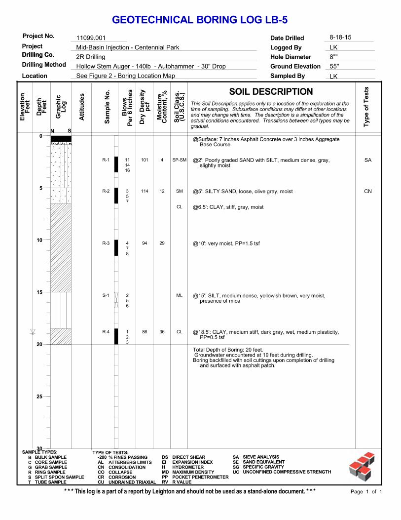
@Surface: 7 inches Asphalt Concrete over 3 inches AggregateBase Course
@2': Poorly graded SAND with SILT, medium dense, gray,slightly moist
@5': SILTY SAND, loose, olive gray, moist
@6.5': CLAY, stiff, gray, moist
@10': very moist, PP=1.5 tsf
@15': SILT, medium dense, yellowish brown, very moist,presence of mica
@18.5': CLAY, medium stiff, dark gray, wet, medium plasticity,PP=0.5 tsf
Total Depth of Boring: 20 feet. Groundwater encountered at 19 feet during drilling.Boring backfilled with soil cuttings upon completion of drilling
and surfaced with asphalt patch.
4
12
29
36
SP-SM
SM
CL
ML
CL
SA
CN
101
114
94
86
R-1
R-2
R-3
S-1
R-4
111416
357
478
256
123
55''
BULK SAMPLECORE SAMPLEGRAB SAMPLERING SAMPLESPLIT SPOON SAMPLETUBE SAMPLE
BCGRST
LK
Hollow Stem Auger - 140lb - Autohammer - 30" Drop
0
5
10
15
20
25
30
So
il C
lass
.
8-18-15
SOIL DESCRIPTION
Sampled By
Drilling Co.Drilling Co.Project
Project No.
See Figure 2 - Boring Location Map
Mid-Basin Injection - Centennial Park
11099.001
Drilling Method8""
Sam
ple
No
.
Fee
t
Hole Diameter
Mo
istu
re
Ground Elevation
Dep
th
Blo
ws
Ele
vati
on
Per
6 In
ches
Page 1 of 1
Att
itu
des
SAMPLE TYPES:
2R Drilling
Co
nte
nt,
%
GEOTECHNICAL BORING LOG LB-5
Logged By
Date Drilled
* * * This log is a part of a report by Leighton and should not be used as a stand-alone document. * * *
LK
Fee
t
S
(U.S
.C.S
.)
Lo
g
Typ
e o
f T
ests
Gra
ph
ic
pcf
Location
Dry
Den
sity
N
This Soil Description applies only to a location of the exploration at thetime of sampling. Subsurface conditions may differ at other locationsand may change with time. The description is a simplification of theactual conditions encountered. Transitions between soil types may begradual.
TYPE OF TESTS:-200ALCNCOCRCU
% FINES PASSINGATTERBERG LIMITSCONSOLIDATIONCOLLAPSECORROSIONUNDRAINED TRIAXIAL
DSEIHMDPPRV
DIRECT SHEAREXPANSION INDEXHYDROMETERMAXIMUM DENSITYPOCKET PENETROMETERR VALUE
SASESGUC
SIEVE ANALYSISSAND EQUIVALENTSPECIFIC GRAVITYUNCONFINED COMPRESSIVE STRENGTH

@Surface: 4 inches Asphalt Concrete over 6 inches AggregateBase Course
@2': SILTY SAND, medium dense, brown, slightly moist
@5': CLAYEY SAND, medium dense, olive, moist, FE stains
@10': wet
@15': CLAYEY SILT, stiff, dark brown, wet
@20: CLAY, medium stiff, dark brown, wet, medium plasticity,PP= 0.5 tsf
Total Depth of Boring: 25 feet. Groundwater encountered at 13.4 feet during drilling.Boring backfilled with soil cuttings upon completion of drilling
and surfaced with asphalt patch.
3
9
30
28
SM
SC
ML
CL
CR
CR
104
114
92
94
R-1
R-2
R-3
S-1
R-4
S-2
131918
5812
358
346
224
123
54''
BULK SAMPLECORE SAMPLEGRAB SAMPLERING SAMPLESPLIT SPOON SAMPLETUBE SAMPLE
BCGRST
LK
Hollow Stem Auger - 140lb - Autohammer - 30" Drop
0
5
10
15
20
25
30
So
il C
lass
.
8-18-15
SOIL DESCRIPTION
Sampled By
Drilling Co.Drilling Co.Project
Project No.
See Figure 2 - Boring Location Map
Mid-Basin Injection - Centennial Park
11099.001
Drilling Method8""
Sam
ple
No
.
Fee
t
Hole Diameter
Mo
istu
re
Ground Elevation
Dep
th
Blo
ws
Ele
vati
on
Per
6 In
ches
Page 1 of 1
Att
itu
des
SAMPLE TYPES:
2R Drilling
Co
nte
nt,
%
GEOTECHNICAL BORING LOG LB-6
Logged By
Date Drilled
* * * This log is a part of a report by Leighton and should not be used as a stand-alone document. * * *
LK
Fee
t
S
(U.S
.C.S
.)
Lo
g
Typ
e o
f T
ests
Gra
ph
ic
pcf
Location
Dry
Den
sity
N
This Soil Description applies only to a location of the exploration at thetime of sampling. Subsurface conditions may differ at other locationsand may change with time. The description is a simplification of theactual conditions encountered. Transitions between soil types may begradual.
TYPE OF TESTS:-200ALCNCOCRCU
% FINES PASSINGATTERBERG LIMITSCONSOLIDATIONCOLLAPSECORROSIONUNDRAINED TRIAXIAL
DSEIHMDPPRV
DIRECT SHEAREXPANSION INDEXHYDROMETERMAXIMUM DENSITYPOCKET PENETROMETERR VALUE
SASESGUC
SIEVE ANALYSISSAND EQUIVALENTSPECIFIC GRAVITYUNCONFINED COMPRESSIVE STRENGTH

@Surface: 3 inches Asphalt Concrete over 7 inches AggregateBase Course
@0.83':SILTY SAND, yellowish brown, dry
@5': medium dense, gray, moist, FE stains
@10': SANDY SILT, loose, olive gray, wet
@15': CLAY, medium stiff, brown, wet, medium plasticity
@20': SILT, loose, gray, wet
@25': CLAY, medium stiff, gray, wet, medium plasticity
Total Depth of Boring: 26.5 feet. Groundwater encountered at 14.9 feet during drilling.Boring backfilled with soil cuttings upon completion of drilling
and surfaced with asphalt patch.
9
26
36
SM
ML
CL
ML
CL
SA
DS
96
99
83
R-1
R-2
S-1
R-3
S-2
4810
456
112
348
112
56''
BULK SAMPLECORE SAMPLEGRAB SAMPLERING SAMPLESPLIT SPOON SAMPLETUBE SAMPLE
BCGRST
LK
Hollow Stem Auger - 140lb - Autohammer - 30" Drop
0
5
10
15
20
25
30
So
il C
lass
.
8-18-15
SOIL DESCRIPTION
Sampled By
Drilling Co.Drilling Co.Project
Project No.
See Figure 2 - Boring Location Map
Mid-Basin Injection - Centennial Park
11099.001
Drilling Method8""
Sam
ple
No
.
Fee
t
Hole Diameter
Mo
istu
re
Ground Elevation
Dep
th
Blo
ws
Ele
vati
on
Per
6 In
ches
Page 1 of 1
Att
itu
des
SAMPLE TYPES:
2R Drilling
Co
nte
nt,
%
GEOTECHNICAL BORING LOG LB-7
Logged By
Date Drilled
* * * This log is a part of a report by Leighton and should not be used as a stand-alone document. * * *
LK
Fee
t
S
(U.S
.C.S
.)
Lo
g
Typ
e o
f T
ests
Gra
ph
ic
pcf
Location
Dry
Den
sity
N
This Soil Description applies only to a location of the exploration at thetime of sampling. Subsurface conditions may differ at other locationsand may change with time. The description is a simplification of theactual conditions encountered. Transitions between soil types may begradual.
TYPE OF TESTS:-200ALCNCOCRCU
% FINES PASSINGATTERBERG LIMITSCONSOLIDATIONCOLLAPSECORROSIONUNDRAINED TRIAXIAL
DSEIHMDPPRV
DIRECT SHEAREXPANSION INDEXHYDROMETERMAXIMUM DENSITYPOCKET PENETROMETERR VALUE
SASESGUC
SIEVE ANALYSISSAND EQUIVALENTSPECIFIC GRAVITYUNCONFINED COMPRESSIVE STRENGTH

@Surface: 3 inches Asphalt Concrete over 5 inches AggregateBase Course
@2': SANDY SILT, medium dense, yellowish brown, slightlymoist
@6.5': CLAY, stiff, brown, dry, medium plasticity, FE stains
Total Depth of Boring: 10 feet.No free groundwater encountered during drilling.Boring backfilled with soil cuttings upon completion of drilling
and surfaced with asphalt patch.
4
15
2
ML
CL
SA108
90
84
R-1
R-2
R-3
111517
578
577
58''
BULK SAMPLECORE SAMPLEGRAB SAMPLERING SAMPLESPLIT SPOON SAMPLETUBE SAMPLE
BCGRST
LK
Hollow Stem Auger - 140lb - Autohammer - 30" Drop
0
5
10
15
20
25
30
So
il C
lass
.
8-18-15
SOIL DESCRIPTION
Sampled By
Drilling Co.Drilling Co.Project
Project No.
See Figure 2 - Boring Location Map
Mid-Basin Injection - Centennial Park
11099.001
Drilling Method8""
Sam
ple
No
.
Fee
t
Hole Diameter
Mo
istu
re
Ground Elevation
Dep
th
Blo
ws
Ele
vati
on
Per
6 In
ches
Page 1 of 1
Att
itu
des
SAMPLE TYPES:
2R Drilling
Co
nte
nt,
%
GEOTECHNICAL BORING LOG LB-8
Logged By
Date Drilled
* * * This log is a part of a report by Leighton and should not be used as a stand-alone document. * * *
LK
Fee
t
S
(U.S
.C.S
.)
Lo
g
Typ
e o
f T
ests
Gra
ph
ic
pcf
Location
Dry
Den
sity
N
This Soil Description applies only to a location of the exploration at thetime of sampling. Subsurface conditions may differ at other locationsand may change with time. The description is a simplification of theactual conditions encountered. Transitions between soil types may begradual.
TYPE OF TESTS:-200ALCNCOCRCU
% FINES PASSINGATTERBERG LIMITSCONSOLIDATIONCOLLAPSECORROSIONUNDRAINED TRIAXIAL
DSEIHMDPPRV
DIRECT SHEAREXPANSION INDEXHYDROMETERMAXIMUM DENSITYPOCKET PENETROMETERR VALUE
SASESGUC
SIEVE ANALYSISSAND EQUIVALENTSPECIFIC GRAVITYUNCONFINED COMPRESSIVE STRENGTH

APPENDIX B
LABORATORY TEST RESULTS
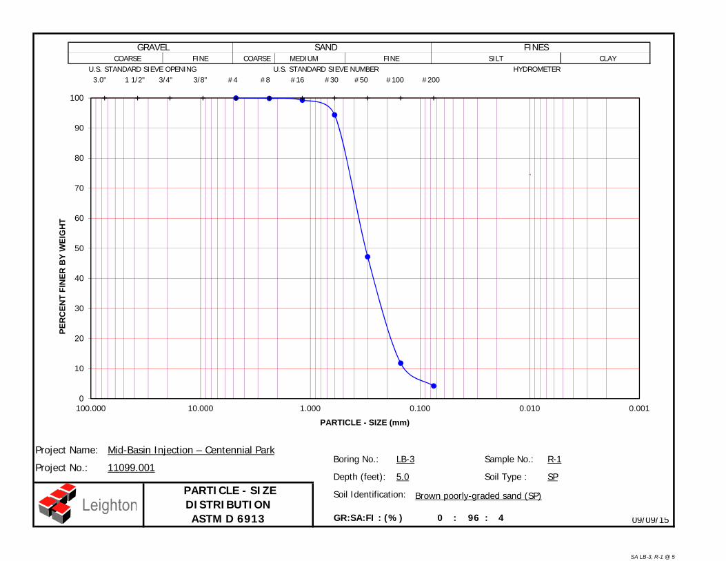
0 : 96 : 4
R-1
09/09/15
Boring No.:
Depth (feet): 5.0 Soil Type :
Project Name:
PARTICLE - SIZE DISTRIBUTION ASTM D 6913
Soil Identification: Brown poorly-graded sand (SP)
SP
GR:SA:FI : (%)
Mid-Basin Injection – Centennial Park
Project No.:LB-3 Sample No.:
11099.001
SANDSILT FINE
HYDROMETER 3.0" 1 1/2" 3/4" 3/8" #4 #8 #16 #30 #50 #100 #200U.S. STANDARD SIEVE OPENING U.S. STANDARD SIEVE NUMBER
GRAVEL FINESFINE CLAY COARSE COARSE MEDIUM
0
10
20
30
40
50
60
70
80
90
100
0.0010.0100.1001.00010.000100.000
PER
CEN
T FI
NER
BY
WEI
GH
T
PARTICLE - SIZE (mm)
"
SA LB-3, R-1 @ 5
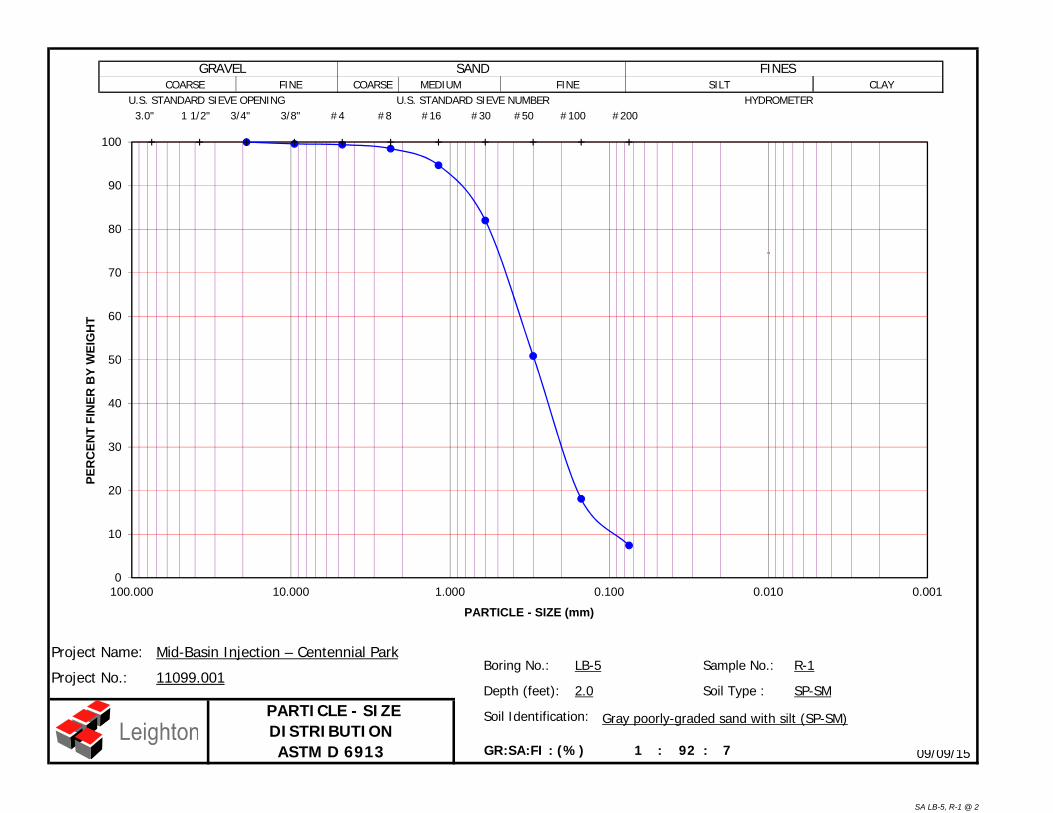
1 : 92 : 7
R-1
09/09/15
Boring No.:
Depth (feet): 2.0 Soil Type :
Project Name:
PARTICLE - SIZE DISTRIBUTION ASTM D 6913
Soil Identification: Gray poorly-graded sand with silt (SP-SM)
SP-SM
GR:SA:FI : (%)
Mid-Basin Injection – Centennial Park
Project No.:LB-5 Sample No.:
11099.001
SANDSILT FINE
HYDROMETER 3.0" 1 1/2" 3/4" 3/8" #4 #8 #16 #30 #50 #100 #200U.S. STANDARD SIEVE OPENING U.S. STANDARD SIEVE NUMBER
GRAVEL FINESFINE CLAY COARSE COARSE MEDIUM
0
10
20
30
40
50
60
70
80
90
100
0.0010.0100.1001.00010.000100.000
PER
CEN
T FI
NER
BY
WEI
GH
T
PARTICLE - SIZE (mm)
"
SA LB-5, R-1 @ 2
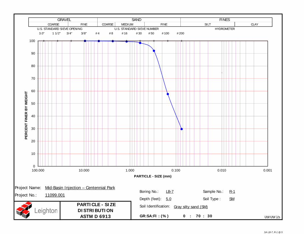
0 : 70 : 30
R-1
09/09/15
Boring No.:
Depth (feet): 5.0 Soil Type :
Project Name:
PARTICLE - SIZE DISTRIBUTION ASTM D 6913
Soil Identification: Gray silty sand (SM)
SM
GR:SA:FI : (%)
Mid-Basin Injection – Centennial Park
Project No.:LB-7 Sample No.:
11099.001
SANDSILT FINE
HYDROMETER 3.0" 1 1/2" 3/4" 3/8" #4 #8 #16 #30 #50 #100 #200U.S. STANDARD SIEVE OPENING U.S. STANDARD SIEVE NUMBER
GRAVEL FINESFINE CLAY COARSE COARSE MEDIUM
0
10
20
30
40
50
60
70
80
90
100
0.0010.0100.1001.00010.000100.000
PER
CEN
T FI
NER
BY
WEI
GH
T
PARTICLE - SIZE (mm)
"
SA LB-7, R-1 @ 5

0 : 45 : 55
R-2
09/09/15
Boring No.:
Depth (feet): 5.0 Soil Type :
Project Name:
PARTICLE - SIZE DISTRIBUTION ASTM D 6913
Soil Identification: Brown sandy silt s(ML)
s(ML)
GR:SA:FI : (%)
Mid-Basin Injection – Centennial Park
Project No.:LB-8 Sample No.:
11099.001
SANDSILT FINE
HYDROMETER 3.0" 1 1/2" 3/4" 3/8" #4 #8 #16 #30 #50 #100 #200U.S. STANDARD SIEVE OPENING U.S. STANDARD SIEVE NUMBER
GRAVEL FINESFINE CLAY COARSE COARSE MEDIUM
0
10
20
30
40
50
60
70
80
90
100
0.0010.0100.1001.00010.000100.000
PER
CEN
T FI
NER
BY
WEI
GH
T
PARTICLE - SIZE (mm)
"
SA LB-8, R-2 @ 5

Initial Final Initial Final Initial Final Initial Final
No Time Readings
0.813 4 7087.1
Degree of Saturation (%)Dry Density (pcf)
0.935
Void Ratio
5.0 1.3
Soil Identification: Light olive brown poorly-graded sand with silt (SP-SM)
Project No.:
Mid-Basin Injection – Centennial Park
09-15
11099.001
Boring No.
Sample No.
Depth (ft.)
Moisture Content (%)
ONE-DIMENSIONAL CONSOLIDATION PROPERTIES of SOILS
ASTM D 2435
22.0 90.9LB-1 R-2
0.2920
0.3420
0.3920
0.4420
0.4920
0.5420
0.5920
0.1 1.0
Def
orm
atio
n D
ial R
eadi
ng (i
n.)
Log of Time (min.)
0.00
1.00
2.00
3.00
4.00
5.00
6.00
7.00
8.000.10 1.00 10.00 100.00
Def
orm
atio
n (%
)
Pressure, p (ksf)
0.0000
0.0500
0.1000
0.1500
0.2000
0.2500
0.3000
0.3500
0.4000
0.4500
0.5000
0.5500
0.0 10.0
Square Root of Time (min.1/2)Inundate with
Tap water
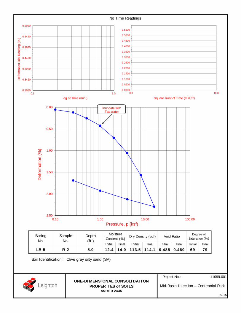
Initial Final Initial Final Initial Final Initial Final
No Time Readings
0.460 69 79113.5
Degree of Saturation (%)Dry Density (pcf)
0.485
Void Ratio
5.0 12.4
Soil Identification: Olive gray silty sand (SM)
Project No.:
Mid-Basin Injection – Centennial Park
09-15
11099.001
Boring No.
Sample No.
Depth (ft.)
Moisture Content (%)
ONE-DIMENSIONAL CONSOLIDATION PROPERTIES of SOILS
ASTM D 2435
14.0 114.1LB-5 R-2
0.2920
0.3420
0.3920
0.4420
0.4920
0.5420
0.5920
0.1 1.0
Def
orm
atio
n D
ial R
eadi
ng (i
n.)
Log of Time (min.)
0.00
0.50
1.00
1.50
2.00
2.500.10 1.00 10.00 100.00
Def
orm
atio
n (%
)
Pressure, p (ksf)
0.0000
0.0500
0.1000
0.1500
0.2000
0.2500
0.3000
0.3500
0.4000
0.4500
0.5000
0.5500
0.0 10.0
Square Root of Time (min.1/2)
Inundate with Tap water

Normal Stress (kip/ft²)Peak Shear Stress (kip/ft²)Shear Stress @ End of Test (ksf)
Sample Type: Ring Deformation Rate (in./min.)
Initial Sample Height (in.)Diameter (in.)Initial Moisture Content (%)
Strength Parameters Dry Density (pcf)C (psf) (o) Saturation (%)
Peak 10.5 40.9 Soil Height Before Shearing (in.)Ultimate 26.5 32.9 Final Moisture Content (%)
08-15
Project No.: 11099.001
12.20.9927
1.000
21.1
Mid-Basin Injection – Centennial ParkDIRECT SHEAR TEST RESULTS
Consolidated Undrained
1.0000.9270.7070.0500
3.1599.5
2.415Soil Identification:
0.9732
3.15
18.5
1.0002.415
0.987320.4
100.7
1.0002.415
12.6
3.15100.5
0.0500
4.0003.5052.6310.0500
12.6
2.000
Light olive brown poorly-graded sand with silt (SP-SM)
Boring No.Sample No.Depth (ft)
LB-4R-15
1.6721.270
0.00
1.00
2.00
3.00
4.00
0 0.1 0.2 0.3
She
ar S
tress
(ksf
)
Horizontal Deformation (in.)
0.0
1.0
2.0
3.0
4.0
0.0 1.0 2.0 3.0 4.0
She
ar S
tress
(ksf
)
Normal Stress (ksf)
DS LB-4, R-1 @ 5

Normal Stress (kip/ft²)Peak Shear Stress (kip/ft²)Shear Stress @ End of Test (ksf)
Sample Type: Ring Deformation Rate (in./min.)
Initial Sample Height (in.)Diameter (in.)Initial Moisture Content (%)
Strength Parameters Dry Density (pcf)C (psf) (o) Saturation (%)
Peak 224.5 37.2 Soil Height Before Shearing (in.)Ultimate 111.5 31.4 Final Moisture Content (%)
08-15
Project No.: 11099.001
99.90.9903
1.000
23.0
Mid-Basin Injection – Centennial ParkDIRECT SHEAR TEST RESULTS
Consolidated Undrained
1.0000.9180.7100.0500
26.2198.7
2.415Soil Identification:
0.9766
26.21
20.8
1.0002.415
0.986221.1
99.8
1.0002.415
101.6
26.2199.3
0.0500
4.0003.2292.5460.0500
102.6
2.000
Olive gray sandy silt s(ML)
Boring No.Sample No.Depth (ft)
LB-7R-210
1.8421.349
0.00
1.00
2.00
3.00
4.00
0 0.1 0.2 0.3
She
ar S
tress
(ksf
)
Horizontal Deformation (in.)
0.0
1.0
2.0
3.0
4.0
0.0 1.0 2.0 3.0 4.0
She
ar S
tress
(ksf
)
Normal Stress (ksf)
DS LB-7, R-2 @ 10

Project Name: Mid-Basin Injection – Centennial Park Tested By : G. Berdy Date: 08/25/15
Project No. : 11099.001 Data Input By: J. Ward Date: 09/09/15
Boring No. LB-4 LB-6
Sample No. B-1R-2 & R-3 combined
Sample Depth (ft) 0-5 5-10
227.27 241.02
221.51 239.49
55.54 67.49
3.47 0.89
100.48 100.35
40 62
3 2
860 860
10:45/11:20 10:45/11:20
35 35
21.6355 21.0186
21.6319 21.0145
0.0036 0.0041
148.14 168.71
153 170
ml of Extract For Titration (B) 15 30
ml of AgNO3 Soln. Used in Titration (C) 0.5 0.9
PPM of Chloride (C -0.2) * 100 * 30 / B 60 70
PPM of Chloride, Dry Wt. Basis 62 71
8.14 7.99
21.7 21.8
TESTS for SULFATE CONTENTCHLORIDE CONTENT and pH of SOILS
SULFATE CONTENT, DOT California Test 417, Part II
Soil Identification:
Moisture Content (%)
Temperature °C
pH Value
Olive SC
pH TEST, DOT California Test 643
CHLORIDE CONTENT, DOT California Test 422
Time In / Time Out
Weight of Soaked Soil (g)
Olive gray SP-SM
Wt. of Crucible + Residue (g)
Wet Weight of Soil + Container (g)
Dry Weight of Soil + Container (g)
Weight of Container (g)
Duration of Combustion (min)
Beaker No.
Crucible No.
Furnace Temperature (°C)
PPM of Sulfate (A) x 41150
PPM of Sulfate, Dry Weight Basis
Wt. of Crucible (g)
Wt. of Residue (g) (A)
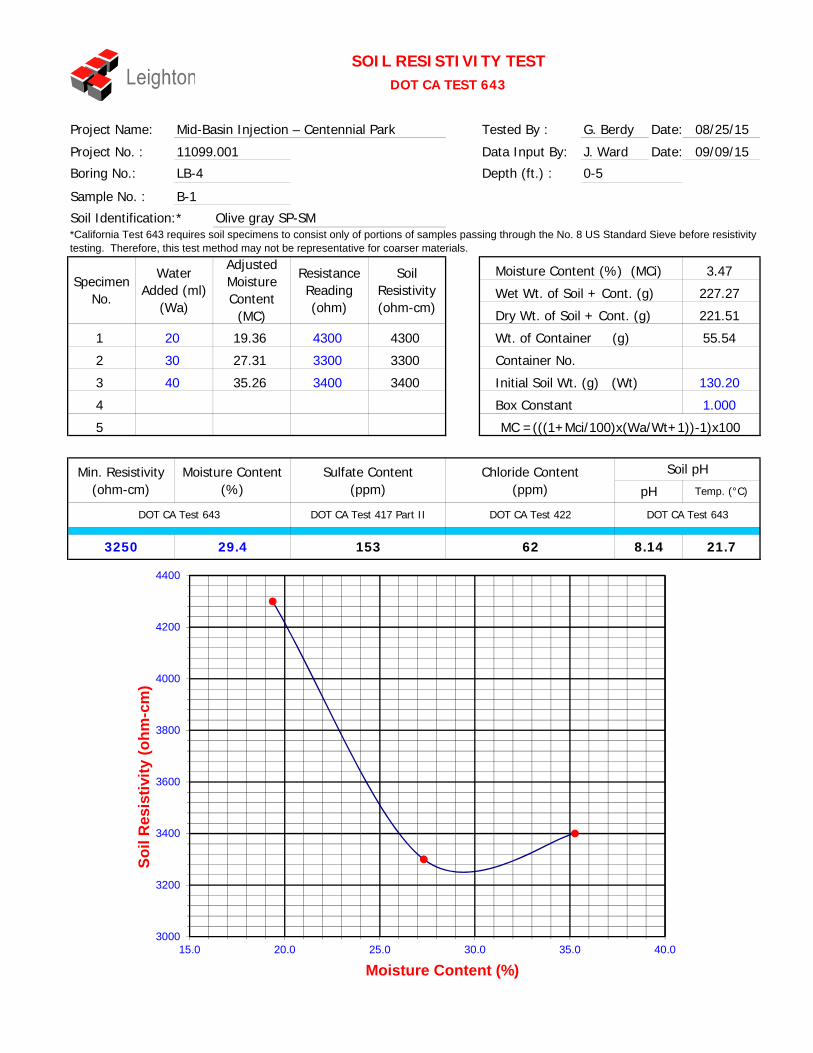
Project Name: Tested By : G. Berdy Date:
Project No. : Data Input By: J. Ward Date:
Boring No.: Depth (ft.) :
Sample No. :
Dry Wt. of Soil + Cont. (g)
4300
Soil Identification:**California Test 643 requires soil specimens to consist only of portions of samples passing through the No. 8 US Standard Sieve before resistivity testing. Therefore, this test method may not be representative for coarser materials.
Wt. of Container (g)19.36 4300
3.47
227.27
Moisture Content (%) (MCi)
Wet Wt. of Soil + Cont. (g)Specimen
No.
1
2
Water Added (ml)
(Wa)
20
Adjusted Moisture Content
(MC)
DOT CA Test 643
1.000
Chloride Content(ohm-cm)
Moisture Content Sulfate Content
5
Min. Resistivity
DOT CA Test 643DOT CA Test 417 Part II DOT CA Test 422
(%) (ppm) (ppm)
4
30
40 130.203 340035.26
3300
3250 29.4 153 62 8.14 21.7
SOIL RESISTIVITY TESTDOT CA TEST 643
Temp. (°C)pH
Soil pH
3300
3400
221.51
55.54
MC =(((1+Mci/100)x(Wa/Wt+1))-1)x100
Mid-Basin Injection – Centennial Park 08/25/15
09/09/15
0-5
11099.001
LB-4
B-1
Container No.
Initial Soil Wt. (g) (Wt)
Box Constant
Olive gray SP-SM
Resistance Reading (ohm)
27.31
Soil Resistivity (ohm-cm)
3000
3200
3400
3600
3800
4000
4200
4400
15.0 20.0 25.0 30.0 35.0 40.0
Soil
Res
istiv
ity (o
hm-c
m)
Moisture Content (%)

Project Name: Tested By : G. Berdy Date:
Project No. : Data Input By: J. Ward Date:
Boring No.: Depth (ft.) :
Sample No. :
Moisture Content (%) (MCi)
Wet Wt. of Soil + Cont. (g)
30
Soil Identification:*
Dry Wt. of Soil + Cont. (g)
Wt. of Container (g)
*California Test 643 requires soil specimens to consist only of portions of samples passing through the No. 8 US Standard Sieve before resistivity testing. Therefore, this test method may not be representative for coarser materials.
0.89
R-2 & R-3 combined
Mid-Basin Injection – Centennial Park 08/26/15
09/09/15
5-10
11099.001
LB-6
241.02
239.49
67.49
21.8
Soil Resistivity (ohm-cm)
Box Constant
SOIL RESISTIVITY TESTDOT CA TEST 643
Temp. (°C)pH
Soil pH
1.000
130.12
1750
1700
1695 38.0 170 71 7.99
DOT CA Test 643DOT CA Test 417 Part II DOT CA Test 422DOT CA Test 643
Specimen No.
1
2
3
200024.15 2000
Resistance Reading (ohm)
Adjusted Moisture Content
(MC)
Water Added (ml)
(Wa)
Initial Soil Wt. (g) (Wt)
5
1700
1800
Container No.175031.90
MC =(((1+Mci/100)x(Wa/Wt+1))-1)x100
4
Sulfate Content Chloride Content(ohm-cm) (%) (ppm) (ppm)
Min. Resistivity Moisture Content
Olive SC
1800
40
50
60
39.66
47.41
1500
1600
1700
1800
1900
2000
2100
20.0 25.0 30.0 35.0 40.0 45.0 50.0
Soil
Res
istiv
ity (o
hm-c
m)
Moisture Content (%)

Tested By: O. Figueroa Date: 08/27/15
Input By: J. Ward Date: 09/09/15LB-4 Depth (ft.): 0-5
X Moist Mechanical Ram
Dry Manual Ram
Mold Volume (ft³) 0.03340 Ram Weight = 10 lb.; Drop = 18 in.
1 2 3 4 5 6
3658 3719 3772 3758
1861 1861 1861 1861
1797 1858 1911 1897
391.2 396.2 422.1 509.2
365.4 362.6 377.8 445.8
38.6 39.3 38.7 39.0
7.89 10.39 13.06 15.59
118.6 122.6 126.1 125.2
109.9 111.1 111.6 108.3
111.5 12.5
PROCEDURE USED
X Procedure ASoil Passing No. 4 (4.75 mm) SieveMold : 4 in. (101.6 mm) diameterLayers : 5 (Five)Blows per layer : 25 (twenty-five)May be used if +#4 is 20% or less
Procedure BSoil Passing 3/8 in. (9.5 mm) SieveMold : 4 in. (101.6 mm) diameterLayers : 5 (Five)Blows per layer : 25 (twenty-five)Use if +#4 is >20% and +3/8 in. is 20% or less
Procedure CSoil Passing 3/4 in. (19.0 mm) SieveMold : 6 in. (152.4 mm) diameterLayers : 5 (Five)Blows per layer : 56 (fifty-six)Use if +3/8 in. is >20% and +¾ in. is <30%
Particle-Size Distribution:
GR:SA:FIAtterberg Limits:
LL,PL,PI
Sample No.:Olive gray poorly-graded sand with silt (SP-SM)
MODIFIED PROCTOR COMPACTION TEST ASTM D 1557
Project No.:Boring No.:
Weight of Container (g)
Weight of Mold (g)
Mid-Basin Injection – Centennial Park
Preparation Method:
Wt. Compacted Soil + Mold (g)
B-1
11099.001
TEST NO.
Soil Identification:
Project Name:
Optimum Moisture Content (%) Maximum Dry Density (pcf)
Net Weight of Soil (g)
Wet Density (pcf)
Dry Density (pcf)
Moisture Content (%)
Wet Weight of Soil + Cont. (g)
Dry Weight of Soil + Cont. (g)
100.0
105.0
110.0
115.0
120.0
0.0 5.0 10.0 15.0 20.
Dry
Den
sity
(pcf
)
Moisture Content (%)
SP. GR. = 2.40SP. GR. = 2.45SP. GR. = 2.50
XX
MX LB-4, B-1 @ 0-5
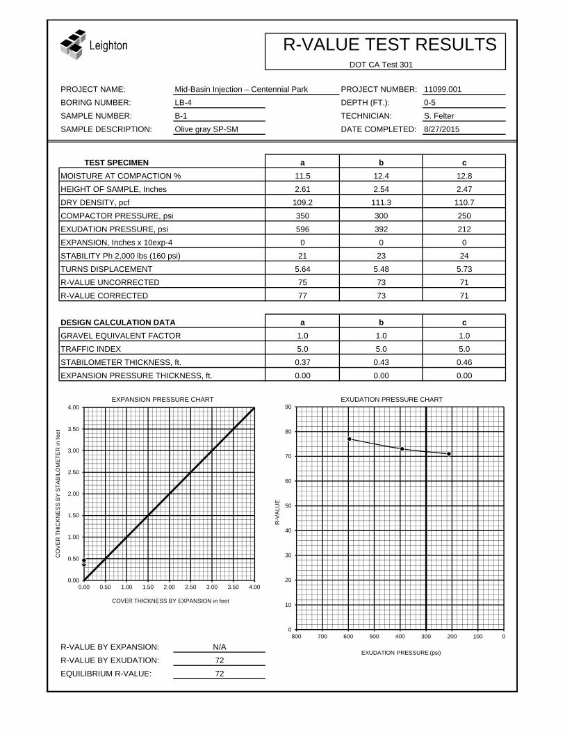
R-VALUE TEST RESULTSDOT CA Test 301
PROJECT NAME: Mid-Basin Injection – Centennial Park PROJECT NUMBER: 11099.001
BORING NUMBER: LB-4 DEPTH (FT.): 0-5
SAMPLE NUMBER: B-1 TECHNICIAN: S. Felter
SAMPLE DESCRIPTION: Olive gray SP-SM DATE COMPLETED: 8/27/2015
TEST SPECIMEN a b cMOISTURE AT COMPACTION % 11.5 12.4 12.8
HEIGHT OF SAMPLE, Inches 2.61 2.54 2.47
DRY DENSITY, pcf 109.2 111.3 110.7
COMPACTOR PRESSURE, psi 350 300 250
EXUDATION PRESSURE, psi 596 392 212
EXPANSION, Inches x 10exp-4 0 0 0
STABILITY Ph 2,000 lbs (160 psi) 21 23 24
TURNS DISPLACEMENT 5.64 5.48 5.73
R-VALUE UNCORRECTED 75 73 71
R-VALUE CORRECTED 77 73 71
DESIGN CALCULATION DATA a b cGRAVEL EQUIVALENT FACTOR 1.0 1.0 1.0
TRAFFIC INDEX 5.0 5.0 5.0
STABILOMETER THICKNESS, ft. 0.37 0.43 0.46
EXPANSION PRESSURE THICKNESS, ft. 0.00 0.00 0.00
EXPANSION PRESSURE CHART EXUDATION PRESSURE CHART
R-VALUE BY EXPANSION: N/A
R-VALUE BY EXUDATION: 72
EQUILIBRIUM R-VALUE: 72
0.00
0.50
1.00
1.50
2.00
2.50
3.00
3.50
4.00
0.00 0.50 1.00 1.50 2.00 2.50 3.00 3.50 4.00
CO
VE
R T
HIC
KN
ES
S B
Y S
TAB
ILO
ME
TER
in fe
et
COVER THICKNESS BY EXPANSION in feet
0
10
20
30
40
50
60
70
80
90
0100200300400500600700800
R-V
ALU
E
EXUDATION PRESSURE (psi)