report of geotechnical data - sagres construction · report of geotechnical data ... (astm d 6913),...
TRANSCRIPT
Corporate HQ: 3015 Dumbarton Road Richmond, Virginia 23228 T 804.264.2701 F 804.264.1202 www.fandr.com
VIRGINIA • NORTH CAROLINA • SOUTH CAROLINA • MARYLAND • DISTRICT OF COLUMBIA
Report of Geotechnical Data
NAMA Rehabilitate Potable Water Lines
Washington, DC
F&R Project No. 72U0289
Prepared For:
CH2M Hill
8720 Stony Point Parkway, Suite 110
Richmond, Virginia 23235
Prepared By:
Froehling & Robertson, Inc.
22923 Quicksilver Drive, Suite 111 Dulles, Virginia 20166
April 24, 2017
FROEHLING & ROBERTSON, INC. Engineering Stability Since 1881
Capital Region, Dulles Operation Center
22923 Quicksilver Drive, Suite 111 Dulles, Virginia 20166‐2013
T 703.996.0123 I F 703.996.0124
Corporate HQ: 3015 Dumbarton Road Richmond, Virginia 23228 T 804.264.2701 F 804.264.1202 www.fandr.com
VIRGINIA • NORTH CAROLINA • SOUTH CAROLINA • MARYLAND • DISTRICT OF COLUMBIA
April 24, 2017 Mr. Howard Lusk, PE, CH2M Hill 8720 Stony Point Parkway, Suite 110 Richmond, Virginia, 23235 Subject: Report of Geotechnical Data
NAMA 151059 D Water Lines Washington, DC F&R Project No. 72U0289 Dear Mr. Lusk: The purpose of this study is to present the results of the subsurface exploration program and geotechnical data collection undertaken by Froehling & Robertson, Inc. (F&R) in connection with the proposed NAMA Rehabilitate Potable Water Lines project. Our services were performed in general accordance with F&R Proposal No. 1772‐00285 dated December 14, 2016, as authorized by your office. The attached report presents our understanding of the project, reviews our exploration procedures, and describes the existing site and general subsurface conditions. We appreciate the opportunity to be of service to you on this project. If you have any questions concerning this report, please contact either of the undersigned.
Respectfully, Froehling & Robertson, Inc.
Parham Safarian Bahri, Oscar R. Merida, J.R, P.E, Staff Engineer Senior Geotechnical Engineer

CH2M HILL NAMA Rehabilitate Potable Water Lines
F&R Project No. 72U0289 April 24, 2017
ii
TABLE OF CONTENTS
SECTION PAGE
1.0 PURPOSE & SCOPE OF SERVICES ............................................................................................... 1
2.0 PROJECT INFORMATION ........................................................................................................... 1
2.1 SITE DESCRIPTION ..................................................................................................................... 1 2.2 PROPOSED CONSTRUCTION ......................................................................................................... 2
3.0 EXPLORATION PROCEDURES ..................................................................................................... 2
3.1 SUBSURFACE EXPLORATION ......................................................................................................... 2 3.2 LABORATORY TESTING ................................................................................................................ 3
4.0 REGIONAL GEOLOGY & SUBSURFACE CONDITIONS ................................................................... 4
4.1 REGIONAL GEOLOGY .................................................................................................................. 4 4.2 SUBSURFACE CONDITIONS ........................................................................................................... 4
4.2.1 General ......................................................................................................................... 4 4.2.2 Fill and Possible Fill Materials ........................................................................................ 5
4.3 SUBSURFACE WATER ................................................................................................................. 5 4.4 LABORATORY TEST RESULTS ........................................................................................................ 6
5.0 LIMITATIONS .............................................................................................................................. 6

CH2M HILL NAMA Rehabilitate Potable Water Lines
F&R Project No. 72U0289 April 24, 2017
iii
APPENDICES
APPENDIX I
Site Location Plan (Drawing No. 1) Boring Location Plans (Drawings No. 2 through 6)
APPENDIX II
Classification of Soils for Engineering Purposes Key to Soil Classification Unified Soil Classification Chart Boring Logs (B‐1 and B‐10)
APPENDIX III
Laboratory Testing Reports
APPENDIX IV
GBA Document “Important Information about Your Geotechnical Engineering Report”

CH2M HILL NAMA Rehabilitate Potable Water Lines
F&R Project No. 72U0289 April 24, 2017
1
1.0 PURPOSE & SCOPE OF SERVICES
The purpose of our involvement in this project was to provide general descriptions of the
subsurface soil conditions encountered at the locations explored. In order to accomplish the
above objectives, we undertook the following scope of services:
Reviewed and summarized available geologic and subsurface information relative to the
project site.
Visited the site to observe existing surface conditions and features.
Performed a stakeout of the boring locations based on the Boring Location Plan provided
by your office using a Series 7 Trimble GPS Unit.
Hired a private utility locator to mark the private utility lines at the site and coordinated
with Miss Utility.
Executed a subsurface program consisting of ten (10) borings, B‐1 through B‐10, drilled to
a depth of 25 feet.
Performed geotechnical laboratory testing on representative soil samples.
Prepared this written report summarizing our work on the project and
providing descriptions of the subsurface conditions encountered.
Our scope of services did not include any design recommendations for the geotechnical aspects of
the project, quantity estimates, preparation of plans or specifications, the identification and
evaluation of environmental related aspects of the project site, or any other item not specifically
included in our scope of work.
2.0 PROJECT INFORMATION
2.1 Site Description
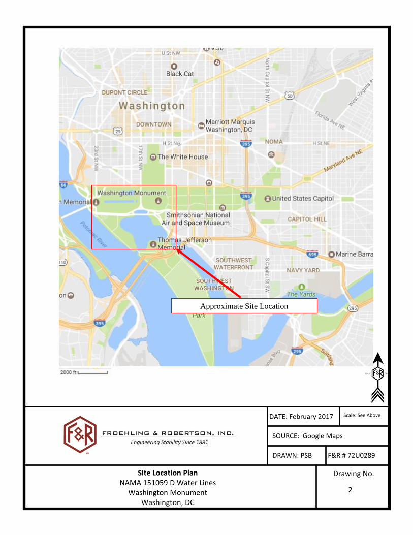
The site is located on the National Mall area from the Washington Monument east to the Lincoln
Memorial and along Independence Avenue SW and Ohio Drive SW to the Jefferson Memorial in
Washington, DC, as shown on the attached Site Location Plan, Drawing No. 1, located in Appendix
A of this report.
The site is relatively flat ranging in elevation from EL 1.9 at Boring B‐10 located near the
intersection of Ohio Drive SW and West Basin Drive SW to elevation EL 10.9 feet at Boring B‐7
located near the intersection of 21st Street NW and Constitution Avenue NW. Ground surface
elevations were determined using a Geo 7 Series Trimble GPS Unit and converted to 1929
Maryland State Plane Datum.

CH2M HILL NAMA Rehabilitate Potable Water Lines
F&R Project No. 72U0289 April 24, 2017
2
2.2 Proposed Construction
We understand that the project consists of the installation of approximately 12,000 LF of new
potable water line that vary in size from 8” to 12” diameter, and approximately 4,000 LF of small
service lines with diameter of generally less than 2”. The work includes appurtenances like fire
hydrants, backflow prevention valves, gate valves, water meters, and water taps.
Horizontal directional drilling with the use of high density polyethylene (HDPE) or polyethylene (PE)
will be utilized for the construction of the proposed water lines due to the sensitive nature of the
park monuments, high traffic, and the landscapes in the construction area.
3.0 EXPLORATION PROCEDURES
3.1 Subsurface Exploration
The subsurface exploration program (consisting of ten test borings designated B‐1 through B‐10)
was performed between March 13, and March 21, 2017, at the approximate locations shown on
the attached Boring Location Plans (Drawings No. 2 through 6 Appendix I of this report). F&R
personnel marked the boring locations in the field using a Series 7 Trimble GPS Unit based on the
drawings provided to us by your office. Mr. Howard Lusk with CH2M Hill oversaw the stake‐out
procedure. In consideration of the methods used in their determination, the boring locations
shown on the attached Boring Location Plan and the elevations shown on the Boring Logs should
be considered approximate.
The test borings were performed in accordance with generally accepted drilling practice using a
truck‐mounted CME‐55 rotary drill rig. Hollow‐stem augers were advanced to pre‐selected
depths, the center plug was removed, and representative soil samples were recovered with a
standard split‐spoon sampler (1.375 in. ID & 2 in. OD) in general accordance with ASTM D 1586,
the Standard Penetration Test. The split‐spoon sampler was driven into the soil by freely dropping
a weight of 140 pounds from a height of 30 inches. The number of blows required to drive the
split‐spoon sampler three consecutive 6‐inch increments is recorded, and the blows of the last
two increments are summed to obtain the Standard Penetration Resistance (N‐value). The N‐
value provides a general indication of in‐situ soil conditions and has been correlated with certain
engineering properties of soils. Standard Penetration Testing was conducted utilizing an
automatic hammer.
Research has shown that the Standard Penetration Resistance (N‐value) determined by the
automatic hammer is different than the N‐value determined by the safety hammer method.
Most corrections that are published in the technical literature are based on the N‐value
determined by the safety hammer method. This is commonly termed N60 as the rope and cathead

CH2M HILL NAMA Rehabilitate Potable Water Lines
F&R Project No. 72U0289 April 24, 2017
3
with a safety hammer delivers about 60 percent of the theoretical energy delivered by a 140‐
pound hammer falling 30 inches. Several researchers have proposed correction factors for the
use of hammers other than the safety hammer. The correction is made by the following
equation:
N60 = Nfield x CE
where Nfield is the value recorded in the field, and CE is the drill rod energy ratio for the hammer
used. A correction factor (CE) of 1.46 should be utilized to convert Nfield values to N60 values as
noted on the Boring Logs. The correction factor is based on previous energy measurements made
for the automatic hammer system utilized. The N‐values reported on the Boring Logs included in
this report are the actual, uncorrected, field derived values (Nfield). It is recommended that
corrected N60 values be used for engineering analysis.
Subsurface water level readings were taken in each of the borings during drilling. All boreholes
were grouted using a grout mixture consisting of bentonite and cement in accordance with the
DCRA requirements up to 18 inches and the top 18 inches were backfilled with sandy loam per
NPS requirements upon completion of drilling.
Split‐spoon soil samples recovered on this project will be stored at F&R’s office for a period of
sixty days. After sixty days, the samples will be discarded unless prior notification is provided to
us in writing.
3.2 Laboratory Testing
Representative portions of the split‐spoon soil samples obtained throughout the exploration
program were placed in glass jars and transported to our laboratory. Bulk samples were also
obtained from the top 5 feet of the borings. In the laboratory, the soil samples were evaluated
by a member of our professional staff in general accordance with techniques outlined in the
visual‐manual identification procedure (ASTM D 2488) and the Unified Soil Classification System
(ASTM D 2487). The soil descriptions and classifications discussed in this report and shown on
the attached Boring Logs are based on visual observations and should be considered
approximate. Copies of the Boring Logs are provided and classification procedures are further
explained in the attached Appendix II.
Laboratory tests were performed on selected split‐spoon and bulk soil samples in general
accordance with the American Society for Testing and Materials (ASTM). The test samples were
selected by your office after reviewing the draft boring logs on April 12, 2017. The tests
performed on the soils samples were Atterberg limits (ASTM D 4318), mechanical sieve analysis

CH2M HILL NAMA Rehabilitate Potable Water Lines
F&R Project No. 72U0289 April 24, 2017
4
(ASTM D 6913), Hydrometer analysis (ASTM D 7928), Standard Proctor (ASTM D 698), and natural
moisture content (ASTM D 2216).
4.0 REGIONAL GEOLOGY & SUBSURFACE CONDITIONS
4.1 Regional Geology
Available geologic references including the The Geologic Map of the Washington West
Quadrangle, District of Columbia, Montgomery and Prince Georges Counties, Maryland, and
Arlington and Fairfax Counties, Virginia by Flemming, Drake and McCartan (1994) indicate that
the site is underlain by artificial fill with heterogeneous composition and texture overlying
Alluvium of stream bottoms and flood plains: swamp deposits, and tidal deposits (Holocene). This
formation contains gravel, sand, silt, and clay and ranges from gray to gray brown in color with
variable thickness up to several feet. The sediment is derived from older terraces, colluvium, and
saprolite, and from fresh crystalline rock.
This alluvium formation consists of mostly quartz sand and silt, illite, and illite‐smectite mixed
layer clay. The sand and silt include feldspar and immature heavy minerals such as hornblende,
epidote, and chlorite.
4.2 Subsurface Conditions
4.2.1 General
The subsurface conditions discussed in the following paragraphs and those shown on the
attached boring logs represent an estimate of the subsurface conditions based on interpretation
of the boring data using normally accepted geotechnical engineering judgments. The transitions
between different soil strata are usually less distinct than those shown on the boring logs.
Sometimes the relatively small sample obtained in the field is insufficient to definitively describe
the origin of the subsurface material. In these cases, we qualify our origin descriptions with
“possible” before the word describing the material’s origin (i.e. possible fill, etc.). Although
individual soil test borings are representative of the subsurface conditions at the boring locations
on the dates shown, they are not necessarily indicative of subsurface conditions at other
locations or at other times. Data from the specific soil test borings are shown on the attached
Boring Logs in Appendix II.
Approximately 6 inches of surficial soils were encountered at the ground surface within the
borings. Surficial soil is typically a dark colored soil material containing roots, fibrous matter,
and/or other organic components, and is generally unsuitable for engineering purposes. F&R has
not performed any laboratory testing to determine the organic content or other horticultural
properties of the observed surficial soil material; therefore, the term surficial soil is not intended

CH2M HILL NAMA Rehabilitate Potable Water Lines
F&R Project No. 72U0289 April 24, 2017
5
to indicate suitability for landscaping and/or other purposes. The surficial soil depths provided in
this report are based on driller observations and should be considered approximate. We note
that the transition from surficial soil to underlying materials may be gradual, and therefore, the
observation and measurement of surficial soil depths are subjective. Actual surficial soil depths
should be expected to vary.
4.2.2 Fill and Possible Fill Materials
Fill and possible fill materials were encountered within the test borings to a termination depth of
approximately 25 feet. Fill and possible fill materials encountered in this exploration consisted
FAT CLAY (CH), ELASTIC SILT (MH) with varying amounts of sand, SILT (ML) with varying amounts
of sand, silty SAND (SM), poorly graded SAND (SM), clayey GRAVEL (GC), silty GRAVEL (GM), and
poorly graded GRAVEL (GP). Standard Penetration Test (SPT) N‐values ranging from 0 to 30 blows
per foot (bpf) were recorded for the soils in this stratum, indicating a very loose to medium dense
state for the granular soils and a very soft to very stiff consistency for the cohesive soils.
4.3 Subsurface Water
Subsurface water was encountered within borings during drilling at elevations ranging from
approximately EL 0.7 to EL ‐8.1 feet. Fluctuations in subsurface water levels and soil moisture
can be anticipated with changes in precipitation, run‐off, and season. The subsurface water
elevations are summarized in Table 1 below.
Table 1 – Ground Water Level Readings
Boring B‐1 B‐2 B‐3 B‐4 B‐5 B‐6 B‐7 B‐8 B‐9 B‐10
Subsurface Water
Elevation (ft)
‐2.3 ‐5.1 ‐5.7 ‐5.3 ‐2.4 0.7 ‐7.1 ‐3.4 ‐6.8 ‐8.1

CH2M HILL NAMA Rehabilitate Potable Water Lines
F&R Project No. 72U0289 April 24, 2017
6
4.4 Laboratory Test Results
The results of the laboratory tests are summarized in Table 2 below and included in Appendix III
of this report.
Table 2 ‐ Summary of Classification Testing
Boring Depth (ft)
LL PL PI Moisture Content
(%)
%Gravel
%Sand
%Fines
USCS Classification
Maximum Dry
Density* (pcf)
Optimum Moisture Content*
(%)
B‐1 4.0 ‐ ‐ ‐ 20.0 0.1 81.7 18.2 ‐ ‐ ‐
B‐1 8.0 52 30 22 45.4 0.0 2.8 97.2 MH ‐ ‐
B‐10 0.5 33 19 14 18.5 9.4 38.9 51.7 CL 115.1 13.1
B‐10 2.0 ‐ ‐ ‐ 17.0 0.0 28.2 71.8 ‐ ‐ ‐
B‐10 10.0 ‐ ‐ ‐ 27.1 0.4 88.9 10.7 ‐ ‐ ‐
B‐2 10.0 ‐ ‐ ‐ 30.3 32.6 48.3 19.0 ‐ ‐ ‐
B‐3 2.0 ‐ ‐ ‐ 13.7 0.0 30.8 69.1 ‐ ‐ ‐
B‐3 6.0 ‐ ‐ ‐ 14.1 34.3 31.9 33.8 ‐ ‐ ‐
B‐4 8.0 NP NP NP 30.7 0.0 73.1 26.9 SM ‐ ‐
B‐5 4.0 61 29 32 39.6 0.0 1.3 98.7 CH ‐ ‐
B‐6 0.5 24 20 4 14.2 5.6 62.6 31.8 SC‐SM 112.1 12.9
B‐6 2.0 ‐ ‐ ‐ 16.1 5.0 67.1 27.9 ‐ ‐ ‐
B‐7 4.0 ‐ ‐ ‐ 33.5 0.0 2.0 98.0 ‐ ‐ ‐
B‐7 8.0 49 29 20 44.0 0.0 1.6 98.4 ML ‐ ‐
B‐8 6.0 ‐ ‐ ‐ 38.1 0.0 6.9 93.1 ‐ ‐ ‐
B‐9 6.0 ‐ ‐ ‐ 4.0 1.7 92.8 5.5 ‐ ‐ ‐ * Maximum dry density and optimum moisture content were determined by ASTM D 698
5.0 LIMITATIONS
This report does not reflect any variations, which may occur beyond the test borings. No warranty,
express or implied, is made.
This report has been prepared for the exclusive use of CH2M Hill to aid in the evaluation of this site
and to assist their office and other design professionals in the design of this project. It is intended
for use with regard to the specific project described herein.
There are important limitations to this and all geotechnical studies. Some of these limitations are
discussed in the information prepared by GBA, which is included in Appendix IV. We ask that you
please review this GBA information.
Regardless of the thoroughness of a subsurface exploration, there is the possibility that conditions
between borings will differ from those at the boring locations, that conditions are not as anticipated
by the designers, or that the construction process has altered the soil conditions. Therefore,

CH2M HILL NAMA Rehabilitate Potable Water Lines
F&R Project No. 72U0289 April 24, 2017
7
experienced geotechnical engineers should evaluate earthwork, pavement, and foundation
construction to verify that the conditions anticipated in design actually exist. Otherwise, we assume
no responsibility for construction compliance with the design concepts, specifications, or
recommendations.
In the event that changes are made in the design or location of the proposed pipeline, the
recommendations presented in the report shall not be considered valid unless the changes are
reviewed by our firm and conclusions of this report modified and/or verified in writing. If this report
is copied or transmitted to a third party, it must be copied or transmitted in its entirety, including
text, attachments, and enclosures. Interpretations based on only a part of this report may not be
valid.
CH2M HILL NAMA Rehabilitate Potable Water Lines
F&R Project No. 72U0289 April 24, 2017
APPENDIX I
DATE: February 2017
SOURCE: Google Maps
DRAWN: PSB F&R # 72U0289
Site Location Plan NAMA 151059 D Water Lines
Washington Monument Washington, DC
Drawing No.
Approximate Project Location
Scale: See Above
2
Approximate Site Location

o
B-01
B-02
B-03
B-05
B-07
B-06
B-08
B-04
B-09
B-10
Date:
Scale:
Drawn:
As ShownFROEHLING & ROBERTSON, INC.Engineering Stability Since 1881
April, 2017
72U-0289
NAMA Rehabilitate Potable Water LinesWashington, DCCH2M Hill
KHH
Drawing No.
2
Boring Location Plan
Index
Drawing No. 3 Drawing No. 4
Drawing No. 5
Drawing No. 6
0 700' 1400'
LEGENDBOREHOLE LOCATIONN

o
o
o
o
o
o
o
10''W
12''W
12''W
10''W
12''W
12''W
10''W
10''W
10''W
10''W
SHRUBS
8" AMERICAN
HOLLY
AMERICAN
4" TWIN
AMERICAN
4" TWIN
CHERRY
4" YOSHINO
UT
B-05
B-07
B-06
Date:
Scale:
Drawn:
As ShownFROEHLING & ROBERTSON, INC.Engineering Stability Since 1881
April, 2017
72U-0289
NAMA Rehabilitate Potable Water LinesWashington, DCCH2M Hill
0 200' 400'
LEGENDBOREHOLE LOCATIONN KHH
Drawing No.
3
Boring Location Plan

o
6''W6''W
6''W
12''W
12''W
12''W
2
''W
6
'
'
W
6''W6''W
6''W
6''W
10''W
10''W
6''W
SHRUBS
8" AMERICAN
HOLLY
AMERICAN
4" TWIN
AMERICAN
4" TWIN
CHERRY
4" YOSHINO
UT
UT
U
T
U
E
UE
U
T
B-02
B-03
Date:
Scale:
Drawn:
As ShownFROEHLING & ROBERTSON, INC.Engineering Stability Since 1881
April, 2017
72U-0289
NAMA Rehabilitate Potable Water LinesWashington, DCCH2M Hill
0 200' 400'
LEGENDBOREHOLE LOCATIONN KHH
Drawing No.
4
Boring Location Plan

o
o
o
6
'
'
W
4''W
4
'
'
W
6
'
'
W
10''W
10''W
6
'
'
W
10''W
10''W
10''W
SHRUBS
SHRUBS
CHERRY
6" YOSHINO
HOLLY
AMERICAN
6" & 8" TWIN
HOLLY
8" AMERICAN
HOLLY
8" AMERICAN
HOLLY
AMERICAN
4" TWIN
HOLLY
AMERICAN
4" TWIN
CHERRY
2" YOSHINO
CHERRY
4" YOSHINO
UE
U
T
UT
UT
UT
UT
UT
U
T
B-05
B-06
B-08
B-04
B-09
Date:
Scale:
Drawn:
As ShownFROEHLING & ROBERTSON, INC.Engineering Stability Since 1881
April, 2017
72U-0289
NAMA Rehabilitate Potable Water LinesWashington, DCCH2M Hill
0 200' 400'
LEGENDBOREHOLE LOCATIONN KHH
Drawing No.
5
Boring Location Plan
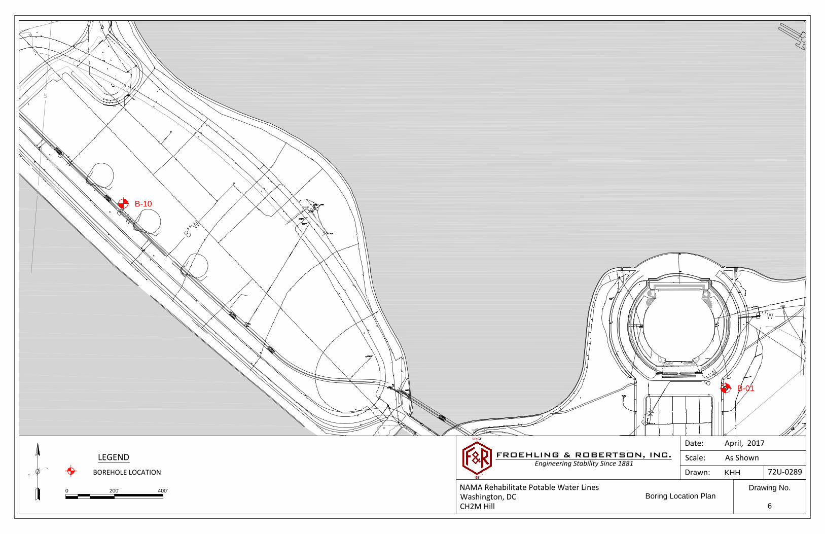
UT
UT
B-01
B-10
Date:
Scale:
Drawn:
As ShownFROEHLING & ROBERTSON, INC.Engineering Stability Since 1881
April, 2017
72U-0289
NAMA Rehabilitate Potable Water LinesWashington, DCCH2M Hill
0 200' 400'
LEGENDBOREHOLE LOCATIONN KHH
Drawing No.
6
Boring Location Plan

CH2M HILL NAMA Rehabilitate Potable Water Lines
F&R Project No. 72U0289 April 24, 2017
APPENDIX II

KEY TO SOIL CLASSIFICATION Correlation of Penetration Resistance with
Relative Density and Consistency
Sands and Gravels Silts and Clays
No. of Relative No. of
Blows, N Density Blows, N Consistency
0 - 4 Very loose 0 - 2 Very soft
5 - 10 Loose 3 - 4 Soft
11 - 30 Medium dense 5 - 8 Firm
31 - 50 Dense 9 - 15 Stiff
Over 50 Very dense 16 - 30 Very stiff
31 - 50 Hard
Over 50 Very hard
Particle Size Identification
(Unified Classification System)
Boulders: Diameter exceeds 12-in. (300-mm)
Cobbles: 3-in. (75-mm) to 12-in. (300-mm) diameter
Gravel: Coarse - ¾-in. (19-mm) to 3 in. (75-mm) diameter
Fine - No. 4 (4.75-mm) sieve to ¾-in. (19-mm) diameter
Sand: Coarse – No. 10 (2.0-mm) to No. 4 (4.76 mm) sieve
Medium – No. 40 (0.425-mm) to No. 10 (2.0-mm) sieve
Fine - No. 200 (0.075-mm) to No. 40 (0.425-mm) sieve
Silt and Clay: Less than No. 200 (0.075-mm) sieve
Modifiers
The modifiers provide our estimate of the amount of silt, clay or sand size particles in the soil
sample.
Approximate
Content
Modifiers
Field Moisture
Description
≤ 5%: Trace Dry Absence of moisture, dusty, dry
to touch
5 to 10%: Few Moist Damp but no visible water
15 to 25%: Little Wet Visible free water, usually soil is
below water table
30 to 45%: Some
50 to 100% Mostly

CLASSIFICATION OF SOILS FOR ENGINEERING PURPOSES
ASTM Designation: D 2487
(Based on Unified Soil Classification System)
Criteria for Assigning Group Symbols and Group Names Using Laboratory Tests A Soil Classification
Group Symbol Group Name B
COARSE-GRAINED
SOILS
More than 50%
retained on No. 200
sieve
Gravels
More than 50%
coarse fraction
retaining on No. 4
sieve
Clean Gravels
Less than 5% finesc
Cu ≥ 4 and 1 ≤ Cc ≤ 3E GW Well graded gravel
F
Cu < 4 and/or 1> Cc >3 E GP Poorly graded gravel
F
Gravels with Fines
More than 12 % finesc
Fines classify as ML or MH GM Silty gravel F,G,H
Fines classify as CL or CH GC
Clayey gravel F,G,H
Sands
50% or more of
coarse fraction
passes No. 4 sieve
Clean Sands
Less than 5% finesD
Cu ≥ 6 and 1 ≤ Cc ≤3 E SW Well-graded sand
I
Cu < 6 and/or 1 > Cc > 3 E SP Poorly graded sand
I
Sands with Fines
More than 12% finesD
Fines classify as ML or MH SM Silty sand G,H,I
Fines classify as CL or CH SC Clayey sand G,H,I
FINE-GRAINED SOILS
50% or more passes
the No. 200 sieve
Silts and Clays
Liquid Limit less than
50
Inorganic PI > 7 and plots on or above
“A” line J
CL Lean clay
K,L,M
PI < 4 or plots below “A” line J ML Silt
K,L,M
Organic Liquid limit - ovendried <0.75
Liquid limit - not dried OL
Organic clay K,L,M,N
Organic silt K,L,M,O
Silts and Clays
Liquid Limit 50 or
more
Inorganic PI plots on or above “A” line CH Fat clay K,L,M
PI plots below “A” line MH Elastic silt K,L,M
Organic Liquid limit - ovendried <0.75
Liquid limit - not dried OH
Organic clay K,L,M,P
Organic silt K,L,M,Q
HIGHLY ORGANIC SOILS Primarily organic matter, dark in color, and organic odor PT Peat
A Based on the material passing the 3-in (75 mm) sieve
B If field sample contained cobbles or boulders, or both, add
“with cobbles or boulders, or both” to group name.
C Gravels with 5 to 12% fines require dual symbols:
GW-GM well-graded gravel with silt
GW-GC well-graded gravel with clay
GP-GM poorly graded gravel with silt
GP-GC poorly graded gravel with clay
D Sands with 5 to 12% fines require dual symbols:
SW-SM well-graded sand with silt
SW-SC well-graded sand with clay
SP-SM poorly graded sand with silt
SP-SC poorly graded sand with clay
ECu=D60/D10 Cc = (D30)
2/(D10*D60)
F If soil contains ≥ 15% sand, add “with sand” to the
group name
G If fines classify as CL-ML, use dual symbol GC-GM, or
SC-SM
H If fines are organic, add “with organic fines” to the
group name
I If soil contains ≥ 15% gravel, add “with gravel” to
group name
J If Atterberg limits plot in hatched area, soils is a CL-ML,
silty clay
K If soil contains 15 to 29% plus No. 200, add “with sand” or
“with gravel,” whichever is predominant
L If soil contains ≥ 30% plus No. 200, predominantly sand,
add “sandy” to group name
M If soil contains ≥ 30% plus No. 200, predominantly gravel,
add “gravelly” to group name
N PI ≥ 4 and plots on or above “A” line
O PI < 4 or plots below “A” line
P PI plots on or above “A” line
Q PI plots below “A” line
SIEVE ANALYSIS Screen (in) Sieve No.
1.5 ¾ 4 10 20 40 60 100 200
D60 = 3 mm
D30 = 0.6 mm
D10 = 0.2 mm
Cu = D60/D10 = (3/0.2) = 15
Cc = (D30)2/(D10*D60) = (0.6
2)/(0.2*3) = 0.6
“U” Line “A” Line
CL or OL
CH or OH
ML or OL
MH or OH
CL-ML
For classification of fine-grained soils and fine-grained fraction of coarse-grained soils:
60
50
40
30
20
10
0 10 20 30 40 50 60 70 80 90 100 110
Liquid Limit (LL)
Plasticity Index (PI)
Equation of “A” line: Horizontal at PI = 4 to LL = 22.5, then PI = 0.73*(LL-20)
Equation of “U” line: Vertical at LL = 16 to PI = 7, then PI = 0.9*(LL-8)
0

LETTERGRAPH
SYMBOLSMAJOR DIVISIONS
SOIL CLASSIFICATION CHART
OH
CH
MH
OL
CL
ML
SC
SM
SP
COARSEGRAINED
SOILS
SW
TYPICAL
DESCRIPTIONS
WELL-GRADED GRAVELS, GRAVEL -SAND MIXTURES, LITTLE OR NOFINES
POORLY-GRADED GRAVELS,GRAVEL - SAND MIXTURES, LITTLEOR NO FINES
SILTY GRAVELS, GRAVEL - SAND -SILT MIXTURES
GC
GM
GP
GW
CLAYEY GRAVELS, GRAVEL - SAND -CLAY MIXTURES
WELL-GRADED SANDS, GRAVELLYSANDS, LITTLE OR NO FINES
POORLY-GRADED SANDS,GRAVELLY SAND, LITTLE OR NOFINES
SILTY SANDS, SAND - SILTMIXTURES
CLAYEY SANDS, SAND - CLAYMIXTURES
INORGANIC SILTS AND VERY FINESANDS, ROCK FLOUR, SILTY ORCLAYEY FINE SANDS OR CLAYEYSILTS WITH SLIGHT PLASTICITY
INORGANIC CLAYS OF LOW TOMEDIUM PLASTICITY, GRAVELLYCLAYS, SANDY CLAYS, SILTYCLAYS, LEAN CLAYS
ORGANIC SILTS AND ORGANICSILTY CLAYS OF LOW PLASTICITY
INORGANIC SILTS, MICACEOUS ORDIATOMACEOUS FINE SAND ORSILTY SOILS
INORGANIC CLAYS OF HIGHPLASTICITY
ORGANIC CLAYS OF MEDIUM TOHIGH PLASTICITY, ORGANIC SILTS
CLEANGRAVELS
GRAVELS WITHFINES
CLEAN SANDS
(LITTLE OR NO FINES)
SANDS WITHFINES
LIQUID LIMITLESS THAN 50
LIQUID LIMITGREATER THAN 50
GRAVELAND
GRAVELLYSOILS
FINEGRAINED
SOILS
SANDAND
SANDYSOILS
SILTSAND
CLAYS
SILTSAND
CLAYS
MORE THAN 50%OF COARSEFRACTION
RETAINED ON NO.4 SIEVE
MORE THAN 50%OF COARSEFRACTION
PASSING ON NO.4 SIEVE
MORE THAN 50%OF MATERIAL ISSMALLER THANNO. 200 SIEVE
SIZE
MORE THAN 50%OF MATERIAL ISLARGER THANNO. 200 SIEVE
SIZE
(LITTLE OR NO FINES)
(APPRECIABLEAMOUNT OF FINES)
(APPRECIABLEAMOUNT OF FINES)
NOTE: DUAL SYMBOLS ARE USED TO INDICATE BORDERLINE SOIL CLASSIFICATIONS
EXISTING FILL FILL EXISTING FILL MATERIALS

1.5
3.5
5.5
7.5
9.5
11.5
13.5
15.5
17.5
19.5
21.5
23.5
25.0
R: Recovery length of thesamples
Water encountered at 6feet during drilling
W: Spoon driven by theweight of the hammerPocket Pen at 8 feet: 0.25TSF
Pocket Pen at 16 feet: 0TSF
6 inches of SURFICIAL SOILFILL, Brown, clayey SAND (SC) with gravel, traceroot matter, loose, moistBrown, sandy ELASTIC SILT (MH), trace rootmatter, firm, moist
Brown, silty SAND (SM), loose to very loose,moist
- Wet at 6 feet
Dark gray, sandy ELASTIC SILT (MH), very soft,wet
Dark gray, silty SAND (SM), contains seams of fatclay, very loose, wet
Boring was terminated at 25 feet. Boring wasgrouted per DCRA requirements up to 18 inches.The top 18 inches was backfilled with sandy loamper NPS requirements.
* Elevation was determined with a Geo 7 SeriesGPS Unit in 1929 Maryland State Plane.
3.2
1.7
-0.3
-4.3
-12.3
-21.3
0.0
2.0
4.0
6.0
8.0
10.0
12.0
14.0
16.0
18.0
20.0
22.0
23.5
0.5
2.0
4.0
8.0
16.0
25.0
9
6
6
2
0
2
0
2
2
0
0
0
3
3-3-6-R=2"
2-3-3-R=18"
3-3-3-R=18"
2-1-1-R=18"
W-W-W-R=18"
W-W-2-R=18"
W-W-W-R=18"
W-W-2-R=18"
W-1-1-R=18"
W-W-W-R=18"
W-W-W-R=18"
W-W-W-R=18"
W-1-2-R=18"
F r o e h l in g & R o b e r t s o n , I n c .
Client: CH2M Hill
City/State: Washington, D.C.Project: NAMA 151059 D Water Lines
*Number of blows required for a 140 lb hammer dropping 30" to drive 2" O.D., 1.375" I.D. sampler a total of 18 inches in three 6" increments.The sum of the second and third increments of penetration is termed the standard penetration resistance, N-Value.
Project No: 72U0289
Elevation Remarks
Boring: B-1 (1 of 1)
Location: See Boring Location PlanHammer Type: Automatic
SampleDepth(feet)
Depth
R
Total Depth: 25.0'Elevation: 3.7 ± *
Driller: Wilhelm
Drilling Method: 2.25" HSA
Date Drilled: 3/20/17
* SampleBlows
Description of Materials(Classification)
N-Value(blows/ft)
BORING LOGBO
RIN
G_L
OG
72U
0289
LO
GS.
GPJ
F&
R.G
DT
4/2
4/17

1.5
3.5
5.5
7.5
9.5
11.5
13.5
15.5
17.5
19.5
21.5
23.5
25.0
R: Recovery length of thesamples
Water encountered at 10feet during drilling
W: Spoon driven by theweight of the hammer
6 inches of SURFICIAL SOILFILL, Brown, silty SAND (SM) with gravel,contains quartz, trace root matter, mediumdense, moistBrown, silty GRAVEL (GM), contains quartz,medium dense, moist
Brown, silty SAND (SM), loose, moist
Brown, clayey GRAVEL (GC), very loose to loose,moist
- Wet at 10 feet
- Trace debris (ceramic) at 14 feet
Dark gray, sandy ELASTIC SILT (MH), very soft tostiff, wet
- Trace gravel, contains quartz, contains woodfragments at 18 feet
Dark gray, silty GRAVEL (GM) with sand, loose,wet
POSSIBLE FILL Brown, FAT CLAY (CH), containswood fragments, stiff, moist
Gray and brown, silty SAND (SM) with gravel,some clay, loose, wet
Boring was terminated at 25 feet. Boring wasgrouted per DCRA requirements up to 18 inches.The top 18 inches was backfilled with sandy loamper NPS requirements.
* Elevation was determined with a Geo 7 SeriesGPS Unit in 1929 Maryland State Plane.
4.4
2.9
-1.1
-3.1
-11.1
-15.1
-17.1
-18.6
-20.1
0.0
2.0
4.0
6.0
8.0
10.0
12.0
14.0
16.0
18.0
20.0
22.0
23.5
0.5
2.0
6.0
8.0
16.0
20.0
22.0
23.5
25.0
13
14
11
10
6
6
2
0
2
12
9
9
8
3-5-8-R=12"
6-6-8-R=18"
3-5-6-R=18"
5-6-4-R=18"
2-3-3-R=18"
2-3-3-R=18"
1-1-1-R=6"
W-W-W-R=6"
2-1-1-R=10"
3-5-7-R=18"
3-4-5-R=6"
4-4-5-R=2"
3-3-5-R=18"
F r o e h l in g & R o b e r t s o n , I n c .
Client: CH2M Hill
City/State: Washington, D.C.Project: NAMA 151059 D Water Lines
*Number of blows required for a 140 lb hammer dropping 30" to drive 2" O.D., 1.375" I.D. sampler a total of 18 inches in three 6" increments.The sum of the second and third increments of penetration is termed the standard penetration resistance, N-Value.
Project No: 72U0289
Elevation Remarks
Boring: B-2 (1 of 1)
Location: See Boring Location PlanHammer Type: Automatic
SampleDepth(feet)
Depth
R
Total Depth: 25.0'Elevation: 4.9 ± *
Driller: Wilhelm
Drilling Method: 2.25" HSA
Date Drilled: 3/16/17
* SampleBlows
Description of Materials(Classification)
N-Value(blows/ft)
BORING LOGBO
RIN
G_L
OG
72U
0289
LO
GS.
GPJ
F&
R.G
DT
4/2
4/17
1.5
3.5
5.5
7.5
9.5
11.5
13.5
15.5
17.5
19.5
21.5
23.5
25.0
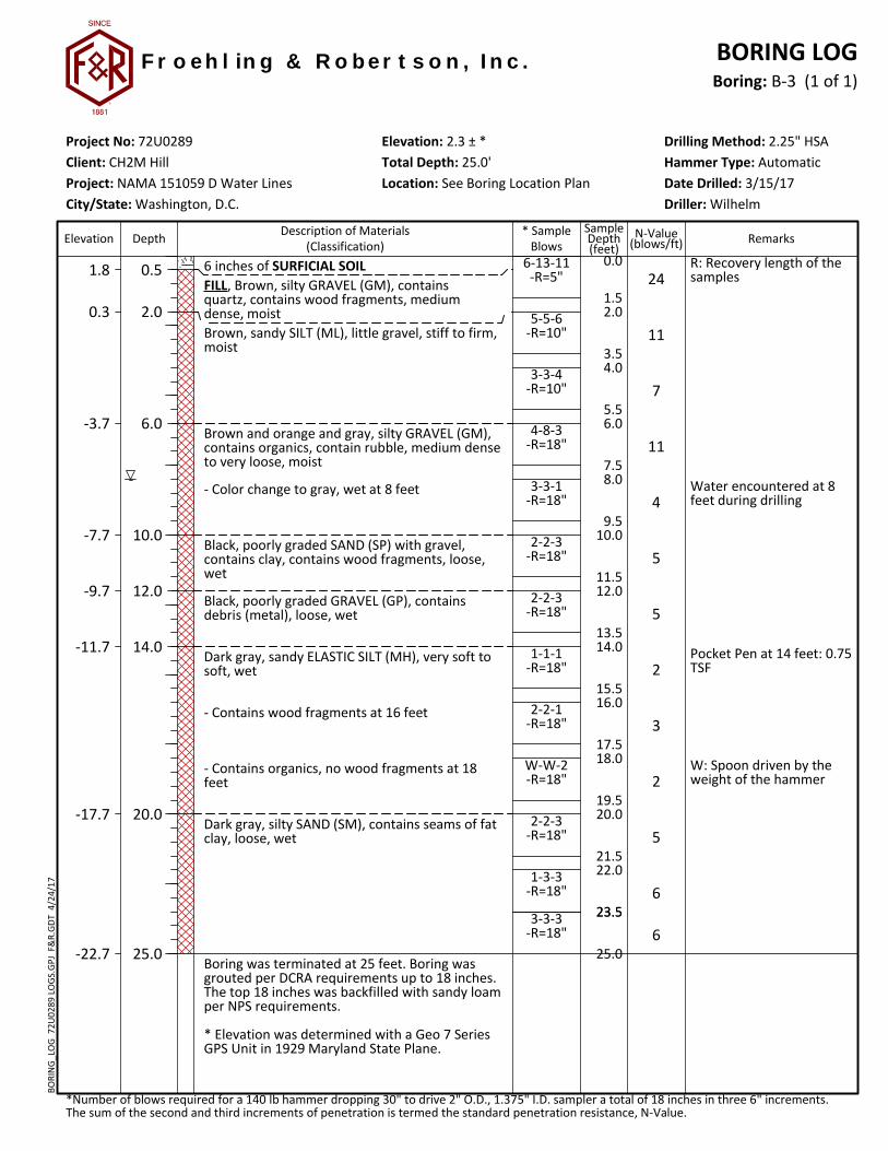
R: Recovery length of thesamples
Water encountered at 8feet during drilling
Pocket Pen at 14 feet: 0.75TSF
W: Spoon driven by theweight of the hammer
6 inches of SURFICIAL SOILFILL, Brown, silty GRAVEL (GM), containsquartz, contains wood fragments, mediumdense, moistBrown, sandy SILT (ML), little gravel, stiff to firm,moist
Brown and orange and gray, silty GRAVEL (GM),contains organics, contain rubble, medium denseto very loose, moist
- Color change to gray, wet at 8 feet
Black, poorly graded SAND (SP) with gravel,contains clay, contains wood fragments, loose,wet
Black, poorly graded GRAVEL (GP), containsdebris (metal), loose, wet
Dark gray, sandy ELASTIC SILT (MH), very soft tosoft, wet
- Contains wood fragments at 16 feet
- Contains organics, no wood fragments at 18feet
Dark gray, silty SAND (SM), contains seams of fatclay, loose, wet
Boring was terminated at 25 feet. Boring wasgrouted per DCRA requirements up to 18 inches.The top 18 inches was backfilled with sandy loamper NPS requirements.
* Elevation was determined with a Geo 7 SeriesGPS Unit in 1929 Maryland State Plane.
1.8
0.3
-3.7
-7.7
-9.7
-11.7
-17.7
-22.7
0.0
2.0
4.0
6.0
8.0
10.0
12.0
14.0
16.0
18.0
20.0
22.0
23.5
0.5
2.0
6.0
10.0
12.0
14.0
20.0
25.0
24
11
7
11
4
5
5
2
3
2
5
6
6
6-13-11-R=5"
5-5-6-R=10"
3-3-4-R=10"
4-8-3-R=18"
3-3-1-R=18"
2-2-3-R=18"
2-2-3-R=18"
1-1-1-R=18"
2-2-1-R=18"
W-W-2-R=18"
2-2-3-R=18"
1-3-3-R=18"
3-3-3-R=18"
F r o e h l in g & R o b e r t s o n , I n c .
Client: CH2M Hill
City/State: Washington, D.C.Project: NAMA 151059 D Water Lines
*Number of blows required for a 140 lb hammer dropping 30" to drive 2" O.D., 1.375" I.D. sampler a total of 18 inches in three 6" increments.The sum of the second and third increments of penetration is termed the standard penetration resistance, N-Value.
Project No: 72U0289
Elevation Remarks
Boring: B-3 (1 of 1)
Location: See Boring Location PlanHammer Type: Automatic
SampleDepth(feet)
Depth
R
Total Depth: 25.0'Elevation: 2.3 ± *
Driller: Wilhelm
Drilling Method: 2.25" HSA
Date Drilled: 3/15/17
* SampleBlows
Description of Materials(Classification)
N-Value(blows/ft)
BORING LOGBO
RIN
G_L
OG
72U
0289
LO
GS.
GPJ
F&
R.G
DT
4/2
4/17
1.5
3.5
5.5
7.5
9.5
11.5
13.5
15.5
17.5
19.5
21.5
23.5
25.0
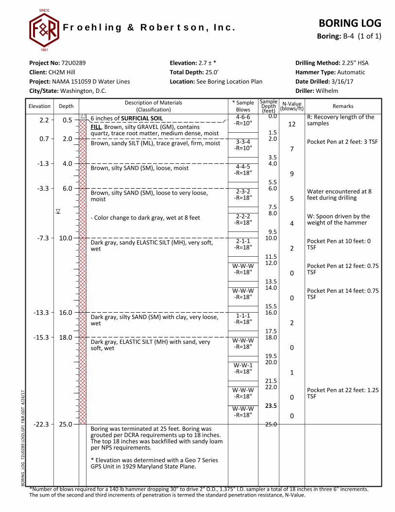
R: Recovery length of thesamples
Pocket Pen at 2 feet: 3 TSF
Water encountered at 8feet during drilling
W: Spoon driven by theweight of the hammer
Pocket Pen at 10 feet: 0TSF
Pocket Pen at 12 feet: 0.75TSF
Pocket Pen at 14 feet: 0.75TSF
Pocket Pen at 22 feet: 1.25TSF
6 inches of SURFICIAL SOILFILL, Brown, silty GRAVEL (GM), containsquartz, trace root matter, medium dense, moistBrown, sandy SILT (ML), trace gravel, firm, moist
Brown, silty SAND (SM), loose, moist
Brown, silty SAND (SM), loose to very loose,moist
- Color change to dark gray, wet at 8 feet
Dark gray, sandy ELASTIC SILT (MH), very soft,wet
Dark gray, silty SAND (SM) with clay, very loose,wet
Dark gray, ELASTIC SILT (MH) with sand, verysoft, wet
Boring was terminated at 25 feet. Boring wasgrouted per DCRA requirements up to 18 inches.The top 18 inches was backfilled with sandy loamper NPS requirements.
* Elevation was determined with a Geo 7 SeriesGPS Unit in 1929 Maryland State Plane.
2.2
0.7
-1.3
-3.3
-7.3
-13.3
-15.3
-22.3
0.0
2.0
4.0
6.0
8.0
10.0
12.0
14.0
16.0
18.0
20.0
22.0
23.5
0.5
2.0
4.0
6.0
10.0
16.0
18.0
25.0
12
7
9
5
4
2
0
0
2
0
1
0
0
4-6-6-R=10"
3-3-4-R=10"
4-4-5-R=18"
2-3-2-R=18"
2-2-2-R=18"
2-1-1-R=18"
W-W-W-R=18"
W-W-W-R=18"
1-1-1-R=18"
W-W-W-R=18"
W-W-1-R=18"
W-W-W-R=18"
W-W-W-R=18"
F r o e h l in g & R o b e r t s o n , I n c .
Client: CH2M Hill
City/State: Washington, D.C.Project: NAMA 151059 D Water Lines
*Number of blows required for a 140 lb hammer dropping 30" to drive 2" O.D., 1.375" I.D. sampler a total of 18 inches in three 6" increments.The sum of the second and third increments of penetration is termed the standard penetration resistance, N-Value.
Project No: 72U0289
Elevation Remarks
Boring: B-4 (1 of 1)
Location: See Boring Location PlanHammer Type: Automatic
SampleDepth(feet)
Depth
R
Total Depth: 25.0'Elevation: 2.7 ± *
Driller: Wilhelm
Drilling Method: 2.25" HSA
Date Drilled: 3/16/17
* SampleBlows
Description of Materials(Classification)
N-Value(blows/ft)
BORING LOGBO
RIN
G_L
OG
72U
0289
LO
GS.
GPJ
F&
R.G
DT
4/2
4/17
1.5
3.5
5.5
7.5
9.5
11.5
13.5
15.5
19.0
21.5
23.5
25.0
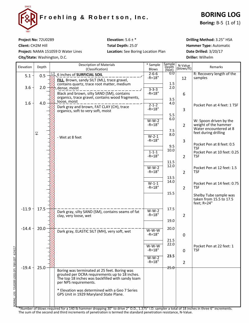
R: Recovery length of thesamples
Pocket Pen at 4 feet: 1 TSF
W: Spoon driven by theweight of the hammerWater encountered at 8feet during drilling
Pocket Pen at 8 feet: 0.5TSFPocket Pen at 10 feet: 0.25TSF
Pocket Pen at 12 feet: 1.5TSF
Pocket Pen at 14 feet: 0.75TSF
Shelby Tube sample wastaken from 15.5 to 17.5feet; R=24"
Pocket Pen at 22 feet: 1TSF
6 inches of SURFICIAL SOILFILL, Brown, sandy SILT (ML), trace gravel,contains quartz, trace root matter, mediumdense, moistBlack and brown, silty SAND (SM), containsorganics, trace gravel, contains wood fragments,loose, moistDark gray and brown, FAT CLAY (CH), traceorganics, soft to very soft, moist
- Wet at 8 feet
Dark gray, silty SAND (SM), contains seams of fatclay, very loose, wet
Dark gray, ELASTIC SILT (MH), very soft, wet
Boring was terminated at 25 feet. Boring wasgrouted per DCRA requirements up to 18 inches.The top 18 inches was backfilled with sandy loamper NPS requirements.
* Elevation was determined with a Geo 7 SeriesGPS Unit in 1929 Maryland State Plane.
5.1
3.6
1.6
-11.9
-14.4
-19.4
0.0
2.0
4.0
6.0
8.0
10.0
12.0
14.0
17.5
20.0
22.0
23.5
0.5
2.0
4.0
17.5
20.0
25.0
12
6
3
2
3
2
2
2
2
0
0
2
2-6-6-R=18"
3-3-3-R=18"
2-1-2-R=18"
W-W-2-R=18"
W-2-1-R=18"
1-1-1-R=18"
W-W-2-R=18"
W-1-1-R=18"
W-W-2-R=18"
W-W-W-R=18"
W-W-W-R=18"
W-W-2-R=18"
F r o e h l in g & R o b e r t s o n , I n c .
Client: CH2M Hill
City/State: Washington, D.C.Project: NAMA 151059 D Water Lines
*Number of blows required for a 140 lb hammer dropping 30" to drive 2" O.D., 1.375" I.D. sampler a total of 18 inches in three 6" increments.The sum of the second and third increments of penetration is termed the standard penetration resistance, N-Value.
Project No: 72U0289
Elevation Remarks
Boring: B-5 (1 of 1)
Location: See Boring Location PlanHammer Type: Automatic
SampleDepth(feet)
Depth
R
Total Depth: 25.0'Elevation: 5.6 ± *
Driller: Wilhelm
Drilling Method: 3.25" HSA
Date Drilled: 3/20/17
* SampleBlows
Description of Materials(Classification)
N-Value(blows/ft)
BORING LOGBO
RIN
G_L
OG
72U
0289
LO
GS.
GPJ
F&
R.G
DT
4/2
4/17

1.5
3.5
5.5
7.5
9.5
13.5
15.5
17.5
19.5
21.5
23.5
25.0
R: Recovery length of thesamplesPocket Pen at 0 feet: 3 TSF
W: Spoon driven by theweight of the hammer
Water encountered at 6feet during drilling
Shelby Tube sample wastaken from 9.5 to 11.5feet; R=20"
Pocket Pen at 14 feet: 0.75TSF
Pocket Pen at 22 feet: 1.5TSF
Pocket Pen at 23.5 feet:1.25 TSF
6 inches of SURFICIAL SOILFILL, Brown, silty SAND (SM), trace root matter,contains organics, some gravel, very loose tomedium dense, moist- Trace gravel at 2 feet
- Color change to dark gray, wet at 6 feet
Dark gray, ELASTIC SILT (MH) with sand, traceorganics, very soft, wet
Dark gray, silty SAND (SM), contains seams of fatclay, very loose, wet
Dark gray, sandy ELASTIC SILT (MH), trace gravel,contains quartz, very soft, wet
Dark gray, silty SAND (SM), contains seams of fatclay, very loose, wet
Dark gray, sandy SILT (ML), very soft, wet
Boring was terminated at 25 feet. Boring wasgrouted per DCRA requirements up to 18 inches.The top 18 inches was backfilled with sandy loamper NPS requirements.
* Elevation was determined with a Geo 7 SeriesGPS Unit in 1929 Maryland State Plane.
6.2
-1.3
-5.3
-7.3
-11.3
-16.8
-18.3
0.0
2.0
4.0
6.0
8.0
12.0
14.0
16.0
18.0
20.0
22.0
23.5
0.5
8.0
12.0
14.0
18.0
23.5
25.0
13
13
7
3
0
3
2
1
0
2
3
0
4-5-8-R=10"
10-6-7-R=12"
4-4-3-R=18"
W-1-2-R=18"
W-W-W-R=18"
2-1-2-R=18"
1-1-1-R=12"
1-W-1-R=18"
W-W-W-R=18"
W-1-1-R=18"
W-1-2-R=18"
W-W-W-R=18"
F r o e h l in g & R o b e r t s o n , I n c .
Client: CH2M Hill
City/State: Washington, D.C.Project: NAMA 151059 D Water Lines
*Number of blows required for a 140 lb hammer dropping 30" to drive 2" O.D., 1.375" I.D. sampler a total of 18 inches in three 6" increments.The sum of the second and third increments of penetration is termed the standard penetration resistance, N-Value.
Project No: 72U0289
Elevation Remarks
Boring: B-6 (1 of 1)
Location: See Boring Location PlanHammer Type: Automatic
SampleDepth(feet)
Depth
R
Total Depth: 25.0'Elevation: 6.7 ± *
Driller: Wilhelm
Drilling Method: 3.25" HSA
Date Drilled: 3/17/17
* SampleBlows
Description of Materials(Classification)
N-Value(blows/ft)
BORING LOGBO
RIN
G_L
OG
72U
0289
LO
GS.
GPJ
F&
R.G
DT
4/2
4/17

1.5
3.5
5.5
7.5
9.5
11.5
13.5
15.5
17.5
19.5
21.5
23.5
25.0
R: Recovery length of thesamples
W: Spoon driven by theweight of the hammer
Pocket Pen at 8 feet: 0.5TSF
Pocket Pen at 14 feet: 0.75TSF
Water encountered at 18feet during drilling
Pocket Pen at 20 feet: 0.25TSF
6 inches of SURFICIAL SOILFILL, Brown, silty SAND (SM) with gravel, tracedebris (glass), medium dense, moist- Color change to black and brown at 2 feet
Gray, sandy SILT (ML), trace gravel, firm, moist
Gray, ELASTIC SILT (MH), contains woodfragments, very soft, moist
Gray, SILT (ML), contains wood fragments, verysoft, moist
Gray, ELASTIC SILT (MH), contains woodfragments, very soft, moist
Dark gray, silty SAND (SM), very loose, moist
- Wet at 18 feet
Dark gray, sandy ELASTIC SILT (MH), very soft,wet
Boring was terminated at 25 feet. Boring wasgrouted per DCRA requirements up to 18 inches.The top 18 inches was backfilled with sandy loamper NPS requirements.
* Elevation was determined with a Geo 7 SeriesGPS Unit in 1929 Maryland State Plane.
10.4
6.9
4.9
2.9
0.9
-5.1
-9.1
-14.1
0.0
2.0
4.0
6.0
8.0
10.0
12.0
14.0
16.0
18.0
20.0
22.0
23.5
0.5
4.0
6.0
8.0
10.0
16.0
20.0
25.0
11
12
6
2
2
0
0
1
2
0
0
0
0
4-5-6-R=18"
3-5-7-R=18"
4-3-3-R=18"
W-1-1-R=18"
W-1-1-R=18"
W-W-W-R=18"
W-W-W-R=18"
W-W-1-R=18"
W-1-1-R=18"
W-W-W-R=18"
W-W-W-R=18"
W-W-W-R=18"
W-W-W-R=18"
F r o e h l in g & R o b e r t s o n , I n c .
Client: CH2M Hill
City/State: Washington, D.C.Project: NAMA 151059 D Water Lines
*Number of blows required for a 140 lb hammer dropping 30" to drive 2" O.D., 1.375" I.D. sampler a total of 18 inches in three 6" increments.The sum of the second and third increments of penetration is termed the standard penetration resistance, N-Value.
Project No: 72U0289
Elevation Remarks
Boring: B-7 (1 of 1)
Location: See Boring Location PlanHammer Type: Automatic
SampleDepth(feet)
Depth
R
Total Depth: 25.0'Elevation: 10.9 ± *
Driller: Wilhelm
Drilling Method: 2.25" HSA
Date Drilled: 3/17/17
* SampleBlows
Description of Materials(Classification)
N-Value(blows/ft)
BORING LOGBO
RIN
G_L
OG
72U
0289
LO
GS.
GPJ
F&
R.G
DT
4/2
4/17

1.5
3.5
5.5
7.5
9.5
11.5
13.5
15.5
17.5
19.5
21.5
23.5
25.0
R: Recovery length of thesamples
Pocket Pen at 2 feet: 3.5TSF
W: Spoon driven by theweight of the hammer
Pocket Pen at 6 feet: 0 TSF
Water encountered at 8feet during drilling
Pocket Pen at 14 feet: 0.25TSF
6 inches of SURFICIAL SOILFILL, Brown, silty SAND (SM), trace gravel,contains quartz, very loose to medium dense
- Trace root matter at 4 feet
Dark gray, ELASTIC SILT (MH), little sand, verysoft, moist
- Trace gravel, trace root matter, wet at 8 feet
- No root matter at 10 feet
- Contains organics at 14 feet
- Contains pieces of bricks at 20 feet
POSSIBLE FILL, Dark gray, silty SAND (SM), veryloose, wet
Dark gray, sandy ELASTIC SILT (MH), very soft,wet
Boring was terminated at 25 feet. Boring wasgrouted per DCRA requirements up to 18 inches.The top 18 inches was backfilled with sandy loamper NPS requirements.
* Elevation was determined with a Geo 7 SeriesGPS Unit in 1929 Maryland State Plane.
4.1
-1.4
-17.4
-18.9
-20.4
0.0
2.0
4.0
6.0
8.0
10.0
12.0
14.0
16.0
18.0
20.0
22.0
23.5
0.5
6.0
22.0
23.5
25.0
8
11
3
0
0
0
0
0
0
0
0
2
1
2-3-5-R=10"
2-4-7-R=18"
3-2-1-R=4"
W-W-W-R=18"
W-W-W-R=18"
W-W-W-R=18"
W-W-W-R=18"
W-W-W-R=18"
W-W-W-R=18"
W-W-W-R=18"
W-W-W-R=18"
W-W-2-R=18"
W-W-1-R=18"
F r o e h l in g & R o b e r t s o n , I n c .
Client: CH2M Hill
City/State: Washington, D.C.Project: NAMA 151059 D Water Lines
*Number of blows required for a 140 lb hammer dropping 30" to drive 2" O.D., 1.375" I.D. sampler a total of 18 inches in three 6" increments.The sum of the second and third increments of penetration is termed the standard penetration resistance, N-Value.
Project No: 72U0289
Elevation Remarks
Boring: B-8 (1 of 1)
Location: See Boring Location PlanHammer Type: Automatic
SampleDepth(feet)
Depth
R
Total Depth: 25.0'Elevation: 4.6 ± *
Driller: Wilhelm
Drilling Method: 2.25" HSA
Date Drilled: 3/21/17
* SampleBlows
Description of Materials(Classification)
N-Value(blows/ft)
BORING LOGBO
RIN
G_L
OG
72U
0289
LO
GS.
GPJ
F&
R.G
DT
4/2
4/17
1.5
3.5
5.5
7.5
9.5
11.5
13.5
15.5
17.5
19.5
21.5
23.5
25.0
R: Recovery length of thesamples
Pocket Pen at 2 feet: 3 TSF
Water encountered at 10feet during drilling
W: Spoon driven by theweight of the hammer
Pocket Pen at 20 feet: 0.5TSF
6 inches of SURFICIAL SOILFILL, Brown, silty GRAVEL (GM), containsquartz, medium dense, moistBrown, sandy SILT (ML), trace gravel, loose,moist
Brown, silty SAND (SM), contains quartz, loose tovery loose, moist
- Color change to gray-brown, wet at 10 feet
Dark gray, sandy SILT (ML), very soft, wet
Dark gray, silty SAND (SM), very loose to loose,wet
Dark gray, sandy ELASTIC SILT (MH), firm, wet
POSSIBLE FILL, Dark gray, silty SAND (SM),contains wood fragments, loose to very loose,wet
Boring was terminated at 25 feet. Boring wasgrouted per DCRA requirements up to 18 inches.The top 18 inches was backfilled with sandy loamper NPS requirements.
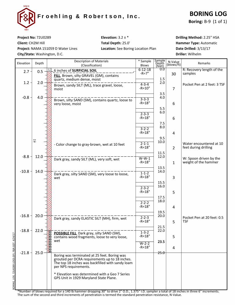
* Elevation was determined with a Geo 7 SeriesGPS Unit in 1929 Maryland State Plane.
2.7
1.2
-0.8
-8.8
-10.8
-16.8
-18.8
-21.8
0.0
2.0
4.0
6.0
8.0
10.0
12.0
14.0
16.0
18.0
20.0
22.0
23.5
0.5
2.0
4.0
12.0
14.0
20.0
22.0
25.0
30
7
6
6
4
2
1
3
5
4
5
5
4
6-12-18-R=7"
4-3-4-R=10"
3-3-3-R=18"
2-3-3-R=18"
3-2-2-R=18"
2-1-1-R=18"
W-W-1-R=18"
1-1-2-R=18"
2-3-2-R=18"
2-2-2-R=18"
2-2-3-R=18"
1-3-2-R=18"
W-2-2-R=18"
F r o e h l in g & R o b e r t s o n , I n c .
Client: CH2M Hill
City/State: Washington, D.C.Project: NAMA 151059 D Water Lines
*Number of blows required for a 140 lb hammer dropping 30" to drive 2" O.D., 1.375" I.D. sampler a total of 18 inches in three 6" increments.The sum of the second and third increments of penetration is termed the standard penetration resistance, N-Value.
Project No: 72U0289
Elevation Remarks
Boring: B-9 (1 of 1)
Location: See Boring Location PlanHammer Type: Automatic
SampleDepth(feet)
Depth
R
Total Depth: 25.0'Elevation: 3.2 ± *
Driller: Wilhelm
Drilling Method: 2.25" HSA
Date Drilled: 3/13/17
* SampleBlows
Description of Materials(Classification)
N-Value(blows/ft)
BORING LOGBO
RIN
G_L
OG
72U
0289
LO
GS.
GPJ
F&
R.G
DT
4/2
4/17

1.5
3.5
5.5
7.5
9.5
11.5
13.5
15.5
17.5
19.5
21.5
23.5
25.0
R: Recovery length of thesamples
Water encountered at 10feet during drilling
6 inches of SURFICIAL SOILFILL, Brown, clayey GRAVEL (GC), containsquartz, medium dense, moistBrown, SILT (ML) with sand, stiff, moist
Brown, silty SAND (SM), very loose to loose,moist
- Color change to dark gray, contains organics at8 feet
- Wet at 10 feet
- Contains seams of fat clay at 20 feet
- No fat clay at 22 feet
Boring was terminated at 25 feet. Boring wasgrouted per DCRA requirements up to 18 inches.The top 18 inches was backfilled with sandy loamper NPS requirements.
* Elevation was determined with a Geo 7 SeriesGPS Unit in 1929 Maryland State Plane.
1.4
-0.1
-2.1
-23.1
0.0
2.0
4.0
6.0
8.0
10.0
12.0
14.0
16.0
18.0
20.0
22.0
23.5
0.5
2.0
4.0
25.0
23
11
8
5
3
5
4
4
2
2
4
2
4
6-11-12-R=18"
5-6-5-R=18"
3-4-4-R=18"
2-2-3-R=18"
1-1-2-R=18"
2-3-2-R=18"
2-2-2-R=18"
2-2-2-R=18"
1-1-1-R=18"
1-1-1-R=18"
2-2-2-R=18"
1-1-1-R=18"
3-2-2-R=18"
F r o e h l in g & R o b e r t s o n , I n c .
Client: CH2M Hill
City/State: Washington, D.C.Project: NAMA 151059 D Water Lines
*Number of blows required for a 140 lb hammer dropping 30" to drive 2" O.D., 1.375" I.D. sampler a total of 18 inches in three 6" increments.The sum of the second and third increments of penetration is termed the standard penetration resistance, N-Value.
Project No: 72U0289
Elevation Remarks
Boring: B-10 (1 of 1)
Location: See Boring Location PlanHammer Type: Automatic
SampleDepth(feet)
Depth
R
Total Depth: 25.0'Elevation: 1.9 ± *
Driller: Wilhelm
Drilling Method: 2.25" HSA
Date Drilled: 3/13/17
* SampleBlows
Description of Materials(Classification)
N-Value(blows/ft)
BORING LOGBO
RIN
G_L
OG
72U
0289
LO
GS.
GPJ
F&
R.G
DT
4/2
4/17

CH2M HILL NAMA Rehabilitate Potable Water Lines
F&R Project No. 72U0289 April 24, 2017
APPENDIX III
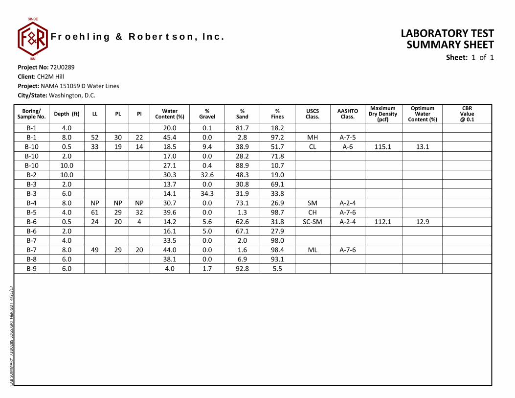
B-1 4.0 20.0 0.1 81.7 18.2B-1 8.0 52 30 22 45.4 0.0 2.8 97.2 MH A-7-5
B-10 0.5 33 19 14 18.5 9.4 38.9 51.7 CL A-6 115.1 13.1B-10 2.0 17.0 0.0 28.2 71.8B-10 10.0 27.1 0.4 88.9 10.7B-2 10.0 30.3 32.6 48.3 19.0B-3 2.0 13.7 0.0 30.8 69.1B-3 6.0 14.1 34.3 31.9 33.8B-4 8.0 NP NP NP 30.7 0.0 73.1 26.9 SM A-2-4B-5 4.0 61 29 32 39.6 0.0 1.3 98.7 CH A-7-6B-6 0.5 24 20 4 14.2 5.6 62.6 31.8 SC-SM A-2-4 112.1 12.9B-6 2.0 16.1 5.0 67.1 27.9B-7 4.0 33.5 0.0 2.0 98.0B-7 8.0 49 29 20 44.0 0.0 1.6 98.4 ML A-7-6B-8 6.0 38.1 0.0 6.9 93.1B-9 6.0 4.0 1.7 92.8 5.5
AASHTOClass.
%Gravel
Sheet: 1 of 1
LL PL %Sand
%Fines
CBRValue@ 0.1
PIOptimum
WaterContent (%)
MaximumDry Density
(pcf)Depth (ft) USCS
Class.
LABORATORY TESTSUMMARY SHEET
Boring/Sample No.
WaterContent (%)
City/State: Washington, D.C.Project: NAMA 151059 D Water LinesClient: CH2M Hill
F r o e h l in g & R o b e r t s o n , I n c .
Project No: 72U0289
R
LAB
SUM
MAR
Y 7
2U02
89 L
OG
S.G
PJ F
&R.
GD
T 4
/21/
17
0
5
10
15
20
25
30
35
40
45
50
55
60
65
70
75
80
85
90
95
100
0.0010.010.1110100Grain Size (mm)
GRAIN SIZEDISTRIBUTION
COBBLES
3/8 3 4 6 810 1416 20 30 40 50 60 100140
9.529.5225.49.5225.4
D600.1510.1490.3190.0060.047
0.0080.0710.01
0.002
%Gravel0.10.4
32.60.0
34.3
%Sand81.788.948.330.831.9
4.010.010.0
2.06.0
%Silt9.8
10.712.941.320.0
%Clay8.30.06.1
27.813.8
200
Cu
U.S. SIEVE NUMBERS HYDROMETER
6 4 3 2 1.5 1 3/4 1/2
Perc
ent F
iner
(By
Wei
ght)
GRAVELcoarse fine coarse medium
SANDfine
SILT OR CLAY
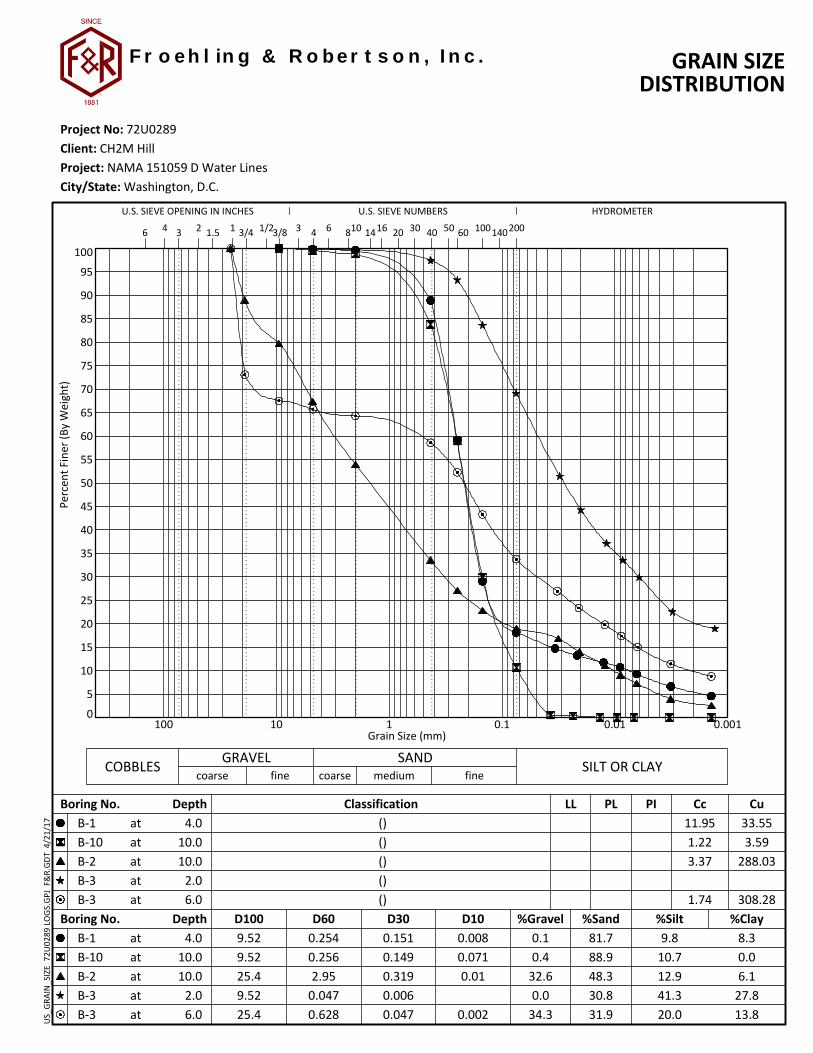
Boring No. DepthB-1B-10B-2B-3B-3
atatatatat
4.010.010.0
2.06.0
Classification () () () () ()
LL PL PI
0.2540.2562.95
0.0470.628
D30 D10
33.553.59
288.03
308.28
Cc11.951.223.37
1.74
U.S. SIEVE OPENING IN INCHES
Boring No. DepthB-1B-10B-2B-3B-3
atatatatat
D100
Client: CH2M Hill
City/State: Washington, D.C.Project: NAMA 151059 D Water Lines
Project No: 72U0289
R
F r o e h l in g & R o b e r t s o n , I n c .U
S_G
RAIN
_SIZ
E 7
2U02
89 L
OG
S.G
PJ F
&R.
GD
T 4
/21/
17

0
5
10
15
20
25
30
35
40
45
50
55
60
65
70
75
80
85
90
95
100
0.0010.010.1110100Grain Size (mm)
GRAIN SIZEDISTRIBUTION
COBBLES
3/8 3 4 6 810 1416 20 30 40 50 60 100140
22
4.762
D600.0020.0790.0010.003
0.035
%Gravel0.00.00.00.0
%Sand2.8
73.11.31.6
8.08.04.08.0
%Silt53.323.638.956.4
%Clay43.93.3
59.841.9
200
Cu
U.S. SIEVE NUMBERS HYDROMETER
6 4 3 2 1.5 1 3/4 1/2
30NP2929
22NP3220
52NP6149
Perc
ent F
iner
(By
Wei
ght)
GRAVELcoarse fine coarse medium
SANDfine
SILT OR CLAY
Boring No. DepthB-1B-4B-5B-7
atatatatat
8.08.04.08.0
ClassificationELASTIC SILT (MH)SILTY SAND (SM)
FAT CLAY (CH)SILT (ML)
LL PL PI
0.010.1370.0050.01
D30 D10
3.86
Cc
1.30
U.S. SIEVE OPENING IN INCHES
Boring No. DepthB-1B-4B-5B-7
atatatatat
D100
Client: CH2M Hill
City/State: Washington, D.C.Project: NAMA 151059 D Water Lines
Project No: 72U0289
R
F r o e h l in g & R o b e r t s o n , I n c .U
S_G
RAIN
_SIZ
E 7
2U02
89 L
OG
S.G
PJ F
&R.
GD
T 4
/21/
17

0
5
10
15
20
25
30
35
40
45
50
55
60
65
70
75
80
85
90
95
100
0.0010.010.1110100Grain Size (mm)
GRAIN SIZEDISTRIBUTION
COBBLES
3/8 3 4 6 810 1416 20 30 40 50 60 100140
4.762
19.1
D600.0030.0050.251 0.115
%Gravel0.00.01.7
%Sand2.06.9
92.8
4.06.06.0
%Silt60.562.94.6
%Clay37.430.20.9
200
Cu
U.S. SIEVE NUMBERS HYDROMETER
6 4 3 2 1.5 1 3/4 1/2
Perc
ent F
iner
(By
Wei
ght)
GRAVELcoarse fine coarse medium
SANDfine
SILT OR CLAY
Boring No. DepthB-7B-8B-9
atatatatat
4.06.06.0
Classification () () ()
LL PL PI
0.0110.02
0.387
D30 D10
3.36
Cc
1.41
U.S. SIEVE OPENING IN INCHES
Boring No. DepthB-7B-8B-9
atatatatat
D100
Client: CH2M Hill
City/State: Washington, D.C.Project: NAMA 151059 D Water Lines
Project No: 72U0289
R
F r o e h l in g & R o b e r t s o n , I n c .U
S_G
RAIN
_SIZ
E 7
2U02
89 L
OG
S.G
PJ F
&R.
GD
T 4
/21/
17

0
10
20
30
40
50
60
0 20 40 60 80 100
PI
22
NP
32
20
PLLL Classification % Natural Water Content
8.0
8.0
4.0
8.0
45.4
30.7
39.6
44.0
ATTERBERG LIMITS
52
NP
61
49
30
NP
29
29
Liquid Limit
Plas
ticity
Inde
x
FinesBoring No. Depth
CH
ML MH
ELASTIC SILT (MH)
SILTY SAND (SM)
FAT CLAY (CH)
SILT (ML)
97.2
26.9
98.7
98.4
CL-ML
CL
Sheet: 1 of 1
B-1
B-4
B-5
B-7
at
at
at
at
Client: CH2M Hill
City/State: Washington, D.C.Project: NAMA 151059 D Water Lines
Project No: 72U0289
R
F r o e h l in g & R o b e r t s o n , I n c .AT
TERB
ERG
_LIM
ITS_
USC
S 7
2U02
89 L
OG
S.G
PJ F
&R.
GD
T 4
/21/
17

0
5
10
15
20
25
30
35
40
45
50
55
60
65
70
75
80
85
90
95
100
0.0010.010.1110100Grain Size (mm)
GRAIN SIZEDISTRIBUTION
COBBLES
3/8 3 4 6 810 1416 20 30 40 50 60 100140
25.44.7625.419.1
D60
0.015
0.089 0.014
%Gravel9.40.05.65.0
%Sand38.928.262.667.1
0.52.00.52.0
%Silt
54.6
24.1
%Clay
17.2
3.8
200
51.7
31.8
Cu
U.S. SIEVE NUMBERS HYDROMETER
6 4 3 2 1.5 1 3/4 1/2
19
20
14
4
33
24
Perc
ent F
iner
(By
Wei
ght)
GRAVELcoarse fine coarse medium
SANDfine
SILT OR CLAY
Boring No. DepthB-10B-10B-6B-6
atatatatat
0.52.00.52.0
ClassificationSANDY LEAN CLAY (CL)
()SILTY, CLAYEY SAND (SC-SM)
()
LL PL PI
0.1380.0530.22
0.297
D30 D10
20.86
Cc
1.87
U.S. SIEVE OPENING IN INCHES
Boring No. DepthB-10B-10B-6B-6
atatatatat
D100
Client: CH2M Hill
City/State: Washington, D.C.Project: NAMA 151059 D Water Lines
Project No: 72U0289
R
F r o e h l in g & R o b e r t s o n , I n c .U
S_G
RAIN
_SIZ
E 7
2U02
89 L
OG
S.G
PJ F
&R.
GD
T 4
/21/
17

0
10
20
30
40
50
60
0 20 40 60 80 100
PI
14
4
PLLL Classification % Natural Water Content
0.5
0.5
18.5
14.2
ATTERBERG LIMITS
33
24
19
20
Liquid Limit
Plas
ticity
Inde
x
FinesBoring No. Depth
CH
ML MH
SANDY LEAN CLAY (CL)
SILTY, CLAYEY SAND (SC-SM)
51.7
31.8
CL-ML
CL
Sheet: 1 of 1
B-10
B-6
at
at
Client: CH2M Hill
City/State: Washington, D.C.Project: NAMA 151059 D Water Lines
Project No: 72U0289
R
F r o e h l in g & R o b e r t s o n , I n c .AT
TERB
ERG
_LIM
ITS_
USC
S 7
2U02
89 L
OG
S.G
PJ F
&R.
GD
T 4
/21/
17
Sp
. g
r. fo
r Z
AV
is a
ssu
me
d
Tested By: JA Checked By: JA
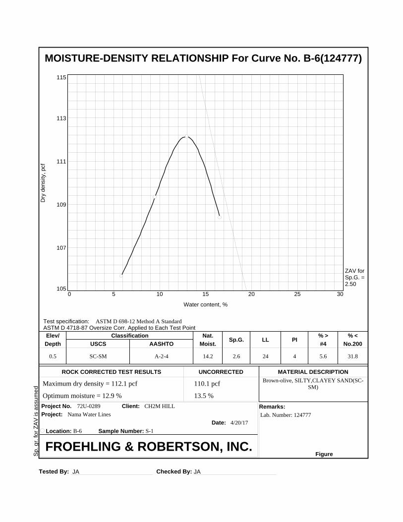
MOISTURE-DENSITY RELATIONSHIP For Curve No. B-6(124777)
Dry
density, pcf
105
107
109
111
113
115
Water content, %
0 5 10 15 20 25 30
ZAV forSp.G. =2.50
Test specification:ASTM D 4718-87 Oversize Corr. Applied to Each Test Point
ASTM D 698-12 Method A Standard
0.5 SC-SM A-2-4 14.2 2.6 24 4 5.6 31.8
Brown-olive, SILTY,CLAYEY SAND(SC-SM)
72U-0289 CH2M HILL
Lab. Number: 124777
4/20/17
Elev/ Classification Nat.Sp.G. LL PI
% > % <
Depth USCS AASHTO Moist. #4 No.200
ROCK CORRECTED TEST RESULTS UNCORRECTED MATERIAL DESCRIPTION
Project No. Client: Remarks:
Project:
Date:
Location: B-6 Sample Number: S-1
FROEHLING & ROBERTSON, INC.Figure
110.1 pcf Maximum dry density = 112.1 pcf
13.5 % Optimum moisture = 12.9 %
Nama Water Lines

Sp
. g
r. fo
r Z
AV
is a
ssu
me
d
Tested By: JA Checked By: JA
MOISTURE-DENSITY RELATIONSHIP For Curve No. B-10(124777
Dry
density, pcf
98
103
108
113
118
123
Water content, %
7.5 10 12.5 15 17.5 20 22.5
ZAV forSp.G. =2.55
Test specification:ASTM D 4718-87 Oversize Corr. Applied to Each Test Point
ASTM D 698-12 Method A Standard
0.5 CL A-6 18.5 2.6 33 14 9.4 51.7
Brown-oranguish olive, SANDY LEANCLAY(CL)
72U-0289 CH2M HILL
Lab. Number: 124777
4/20/17
Elev/ Classification Nat.Sp.G. LL PI
% > % <
Depth USCS AASHTO Moist. #4 No.200
ROCK CORRECTED TEST RESULTS UNCORRECTED MATERIAL DESCRIPTION
Project No. Client: Remarks:
Project:
Date:
Location: B-10 Sample Number: S-1
FROEHLING & ROBERTSON, INC.Figure
111.8 pcf Maximum dry density = 115.1 pcf
14.2 % Optimum moisture = 13.1 %
Nama Water Lines

CH2M HILL NAMA Rehabilitate Potable Water Lines
F&R Project No. 72U0289 April 24, 2017
APPENDIX IV

Geotechnical-Engineering ReportImportant Information about This
Subsurface problems are a principal cause of construction delays, cost overruns, claims, and disputes.
While you cannot eliminate all such risks, you can manage them. The following information is provided to help.
The Geoprofessional Business Association (GBA) has prepared this advisory to help you – assumedly a client representative – interpret and apply this geotechnical-engineering report as effectively as possible. In that way, clients can benefit from a lowered exposure to the subsurface problems that, for decades, have been a principal cause of construction delays, cost overruns, claims, and disputes. If you have questions or want more information about any of the issues discussed below, contact your GBA-member geotechnical engineer. Active involvement in the Geoprofessional Business Association exposes geotechnical engineers to a wide array of risk-confrontation techniques that can be of genuine benefit for everyone involved with a construction project.
Geotechnical-Engineering Services Are Performed for Specific Purposes, Persons, and ProjectsGeotechnical engineers structure their services to meet the specific needs of their clients. A geotechnical-engineering study conducted for a given civil engineer will not likely meet the needs of a civil-works constructor or even a different civil engineer. Because each geotechnical-engineering study is unique, each geotechnical-engineering report is unique, prepared solely for the client. Those who rely on a geotechnical-engineering report prepared for a different client can be seriously misled. No one except authorized client representatives should rely on this geotechnical-engineering report without first conferring with the geotechnical engineer who prepared it. And no one – not even you – should apply this report for any purpose or project except the one originally contemplated.
Read this Report in FullCostly problems have occurred because those relying on a geotechnical-engineering report did not read it in its entirety. Do not rely on an executive summary. Do not read selected elements only. Read this report in full.
You Need to Inform Your Geotechnical Engineer about ChangeYour geotechnical engineer considered unique, project-specific factors when designing the study behind this report and developing the confirmation-dependent recommendations the report conveys. A few typical factors include: • the client’s goals, objectives, budget, schedule, and risk-management preferences; • the general nature of the structure involved, its size, configuration, and performance criteria; • the structure’s location and orientation on the site; and • other planned or existing site improvements, such as retaining walls, access roads, parking lots, and underground utilities.
Typical changes that could erode the reliability of this report include those that affect:• the site’s size or shape;• the function of the proposed structure, as when it’s changed from a parking garage to an office building, or from a light-industrial plant to a refrigerated warehouse;• the elevation, configuration, location, orientation, or weight of the proposed structure;• the composition of the design team; or• project ownership.
As a general rule, always inform your geotechnical engineer of project changes – even minor ones – and request an assessment of their impact. The geotechnical engineer who prepared this report cannot accept responsibility or liability for problems that arise because the geotechnical engineer was not informed about developments the engineer otherwise would have considered.
This Report May Not Be ReliableDo not rely on this report if your geotechnical engineer prepared it:• for a different client;• for a different project;• for a different site (that may or may not include all or a portion of the original site); or • before important events occurred at the site or adjacent to it; e.g., man-made events like construction or environmental remediation, or natural events like floods, droughts, earthquakes, or groundwater fluctuations.
Note, too, that it could be unwise to rely on a geotechnical-engineering report whose reliability may have been affected by the passage of time, because of factors like changed subsurface conditions; new or modified codes, standards, or regulations; or new techniques or tools. If your geotechnical engineer has not indicated an “apply-by” date on the report, ask what it should be, and, in general, if you are the least bit uncertain about the continued reliability of this report, contact your geotechnical engineer before applying it. A minor amount of additional testing or analysis – if any is required at all – could prevent major problems.
Most of the “Findings” Related in This Report Are Professional OpinionsBefore construction begins, geotechnical engineers explore a site’s subsurface through various sampling and testing procedures. Geotechnical engineers can observe actual subsurface conditions only at those specific locations where sampling and testing were performed. The data derived from that sampling and testing were reviewed by your geotechnical engineer, who then applied professional judgment to form opinions about subsurface conditions throughout the site. Actual sitewide-subsurface conditions may differ – maybe significantly – from those indicated in this report. Confront that risk by retaining your geotechnical engineer to serve on the design team from project start to project finish, so the individual can provide informed guidance quickly, whenever needed.
This Report’s Recommendations Are Confirmation-DependentThe recommendations included in this report – including any options or alternatives – are confirmation-dependent. In other words, they are not final, because the geotechnical engineer who developed them relied heavily on judgment and opinion to do so. Your geotechnical engineer can finalize the recommendations only after observing actual subsurface conditions revealed during construction. If through observation your geotechnical engineer confirms that the conditions assumed to exist actually do exist, the recommendations can be relied upon, assuming no other changes have occurred. The geotechnical engineer who prepared this report cannot assume responsibility or liability for confirmation-dependent recommendations if you fail to retain that engineer to perform construction observation.
This Report Could Be MisinterpretedOther design professionals’ misinterpretation of geotechnical-engineering reports has resulted in costly problems. Confront that risk by having your geotechnical engineer serve as a full-time member of the design team, to: • confer with other design-team members, • help develop specifications, • review pertinent elements of other design professionals’ plans and specifications, and • be on hand quickly whenever geotechnical-engineering guidance is needed. You should also confront the risk of constructors misinterpreting this report. Do so by retaining your geotechnical engineer to participate in prebid and preconstruction conferences and to perform construction observation.
Give Constructors a Complete Report and GuidanceSome owners and design professionals mistakenly believe they can shift unanticipated-subsurface-conditions liability to constructors by limiting the information they provide for bid preparation. To help prevent the costly, contentious problems this practice has caused, include the complete geotechnical-engineering report, along with any attachments or appendices, with your contract documents, but be certain to note conspicuously that you’ve included the material for informational purposes only. To avoid misunderstanding, you may also want to note that “informational purposes” means constructors have no right to rely on the interpretations, opinions, conclusions, or recommendations in the report, but they may rely on the factual data relative to the specific times, locations, and depths/elevations referenced. Be certain that constructors know they may learn about specific project requirements, including options selected from the report, only from the design drawings and specifications. Remind constructors that they may
perform their own studies if they want to, and be sure to allow enough time to permit them to do so. Only then might you be in a position to give constructors the information available to you, while requiring them to at least share some of the financial responsibilities stemming from unanticipated conditions. Conducting prebid and preconstruction conferences can also be valuable in this respect.
Read Responsibility Provisions CloselySome client representatives, design professionals, and constructors do not realize that geotechnical engineering is far less exact than other engineering disciplines. That lack of understanding has nurtured unrealistic expectations that have resulted in disappointments, delays, cost overruns, claims, and disputes. To confront that risk, geotechnical engineers commonly include explanatory provisions in their reports. Sometimes labeled “limitations,” many of these provisions indicate where geotechnical engineers’ responsibilities begin and end, to help others recognize their own responsibilities and risks. Read these provisions closely. Ask questions. Your geotechnical engineer should respond fully and frankly.
Geoenvironmental Concerns Are Not CoveredThe personnel, equipment, and techniques used to perform an environmental study – e.g., a “phase-one” or “phase-two” environmental site assessment – differ significantly from those used to perform a geotechnical-engineering study. For that reason, a geotechnical-engineering report does not usually relate any environmental findings, conclusions, or recommendations; e.g., about the likelihood of encountering underground storage tanks or regulated contaminants. Unanticipated subsurface environmental problems have led to project failures. If you have not yet obtained your own environmental information, ask your geotechnical consultant for risk-management guidance. As a general rule, do not rely on an environmental report prepared for a different client, site, or project, or that is more than six months old.
Obtain Professional Assistance to Deal with Moisture Infiltration and MoldWhile your geotechnical engineer may have addressed groundwater, water infiltration, or similar issues in this report, none of the engineer’s services were designed, conducted, or intended to prevent uncontrolled migration of moisture – including water vapor – from the soil through building slabs and walls and into the building interior, where it can cause mold growth and material-performance deficiencies. Accordingly, proper implementation of the geotechnical engineer’s recommendations will not of itself be sufficient to prevent moisture infiltration. Confront the risk of moisture infiltration by including building-envelope or mold specialists on the design team. Geotechnical engineers are not building-envelope or mold specialists.
Copyright 2016 by Geoprofessional Business Association (GBA). Duplication, reproduction, or copying of this document, in whole or in part, by any means whatsoever, is strictly prohibited, except with GBA’s specific written permission. Excerpting, quoting, or otherwise extracting wording from this document is permitted only with the express written permission of GBA, and only for purposes of scholarly research or book review. Only members of GBA may use this document or its wording as a complement to or as an element of a report of any
kind. Any other firm, individual, or other entity that so uses this document without being a GBA member could be committing negligent
Telephone: 301/565-2733e-mail: [email protected] www.geoprofessional.org