getting started with aves blue - ez.analog.com fileanalog devices, inc. getting started with aves...
TRANSCRIPT
Analog Devices, Inc.
Getting started with AVES Blue Build 3.03.1243
AVES Blue 3-10-2016
1
Table of Contents Introduction ............................................................................................................................................ 4
Words and Abbreviations used ............................................................................................................... 4
Setting up AVES Blue for full use ............................................................................................................ 5
Installing AVES Blue............................................................................................................................. 5
Installing IronPython 2.7.5 (optional) ................................................................................................. 7
Installing SDP Drivers .......................................................................................................................... 7
Installing FTDI Drivers ......................................................................................................................... 7
AVES Basics ............................................................................................................................................. 8
Status Indicators ................................................................................................................................. 8
Progress Bar .................................................................................................................................... 8
I2C Status Box ................................................................................................................................. 8
Refresh Status Box .......................................................................................................................... 8
Connection Status Bar ..................................................................................................................... 8
The Connection Window ........................................................................................................................ 9
Connecting to a board ........................................................................................................................ 9
Connecting to a Aardvark chip ...................................................................................................... 10
Connecting to ADS7 (SDP) ............................................................................................................. 10
Connecting to AdvantivSerial ........................................................................................................ 11
Connecting to a AdvantivUSB ....................................................................................................... 11
Connecting to a Cypress chip ........................................................................................................ 11
Connecting to a FTDI Chip ............................................................................................................. 11
Connecting to a SDP Board ........................................................................................................... 12
Connecting to UBoot ..................................................................................................................... 12
Connection Established ................................................................................................................. 14
Log file ............................................................................................................................................... 15
Monitor Window ................................................................................................................................... 15
The File Menu ....................................................................................................................................... 16
Project ............................................................................................................................................... 16
Device ................................................................................................................................................ 16
ScriptX ............................................................................................................................................... 16
Probe ................................................................................................................................................. 16
IronPython ........................................................................................................................................ 16
Re-dock All ........................................................................................................................................ 16
Remove Active Project ...................................................................................................................... 16
Remove Active Device ....................................................................................................................... 16
2
Exit..................................................................................................................................................... 16
Settings.................................................................................................................................................. 17
Preferences ....................................................................................................................................... 17
Script Editor ................................................................................................................................... 17
EDID Editor .................................................................................................................................... 17
Python Editor ................................................................................................................................ 17
Run Time Section .......................................................................................................................... 17
Start up .......................................................................................................................................... 18
Bus Configurator ............................................................................................................................... 19
Display Re-Configuration .................................................................................................................. 20
Tools ...................................................................................................................................................... 22
Device Validation .............................................................................................................................. 22
The IronPython Window ....................................................................................................................... 23
The Add button ................................................................................................................................. 23
The Edit button ................................................................................................................................. 23
Running Files ..................................................................................................................................... 24
The Configure Window ..................................................................................................................... 24
Paths.............................................................................................................................................. 24
Assemblies .................................................................................................................................... 24
Probe ..................................................................................................................................................... 25
File Menu ...................................................................................................................................... 25
Buttons above the Grid ................................................................................................................. 25
The Register Grid........................................................................................................................... 27
ScriptX (Scripts Tab) .............................................................................................................................. 29
Device Tab ............................................................................................................................................. 30
Introduction ...................................................................................................................................... 30
Menu Buttons ................................................................................................................................... 30
Addressing ..................................................................................................................................... 30
Consoles ........................................................................................................................................ 31
Capture .......................................................................................................................................... 33
EDID ............................................................................................................................................... 33
Read .............................................................................................................................................. 33
Search Tab ......................................................................................................................................... 34
Register Map ..................................................................................................................................... 35
FAQ ........................................................................................................................................................ 38
How do I delete a Project Tab? ......................................................................................................... 38
3
Does the Register Dump (capture button) do a read-back from the device? .................................. 38
How do I add a field to the console window?................................................................................... 38
How do I know when an I2C operation has failed? .......................................................................... 38
Can I have one project connected to one connection and another project with a different
connection? ...................................................................................................................................... 38
What is for Null connection for? ....................................................................................................... 38
Can I create my own plug-in connections? ....................................................................................... 38
How do I re-dock all of the tabs? ...................................................................................................... 38
What is the probe function for? ....................................................................................................... 38
My USB chip is listed in AVES but isn’t working, why? ..................................................................... 38
What is the difference between Project and Device? ...................................................................... 38
Why is the ScriptX button disabled? ................................................................................................. 38
What is the IronPython tab for? ....................................................................................................... 39
What are the installation requirements for AVES? ........................................................................... 39
Do I need to uninstall a previous version of AVES (e.g. AVES3) if I am installing AVES Blue? .......... 39
Does uninstalling AVES Blue delete old user files? ........................................................................... 39
References ............................................................................................................................................ 40
4
Introduction This is an installation and user guide for AVES Blue. It is subject to change.
AVES Blue is a suite of tools used to evaluate Analog Devices Video Boards. It contains register maps,
the ability to run AVES Scripts to program multiple registers, to run IronPython Scripts, debug
consoles, probes and more.
If you have any questions or comments please start a discussion at the Video Support Community
found at Video Support Community.
Words and Abbreviations used AVES – Advantiv Video Evaluation Software [1]. Software used to evaluate ADV products. This guide
covers how to install and use it.
SDP – System Demonstration Platform. A range of hardware products used to simplify the evaluation
of ADI components and boards [2].
ADV – Analog Devices Video. A department of Analog Devices who’s products AVES was built to
evaluate.
FTDI - Future Technology Devices International. A semiconductor company that specialises in
products for USB communications and display systems [3].
IronPython – A port of the Python programming language that runs on the .NET framework [4].
DLL – Dynamic Link Library. A binary file containing a programming library that can share across
programs. It is used to make code modular as the one DLL can be shared between programs instead
of having each program have a copy of the library [5].
XML - Extensible Markup Language. It is a text-based format that allows for the structuring of
electronic documents. It is similar to HTML in that tags are used to organise the data [6].
I2C – Inter IC. A communication bus designed by Philips (now NXP) to allow easy communications
between integrated circuits. It uses two wires for communications, a data lane and a clock lane [7].
5
Setting up AVES Blue for full use
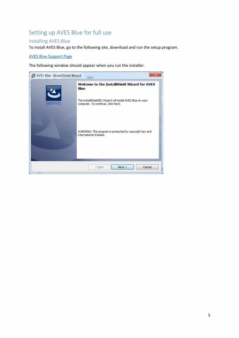
Installing AVES Blue To install AVES Blue, go to the following site, download and run the setup program.
AVES Blue Support Page
The following window should appear when you run the installer.
6
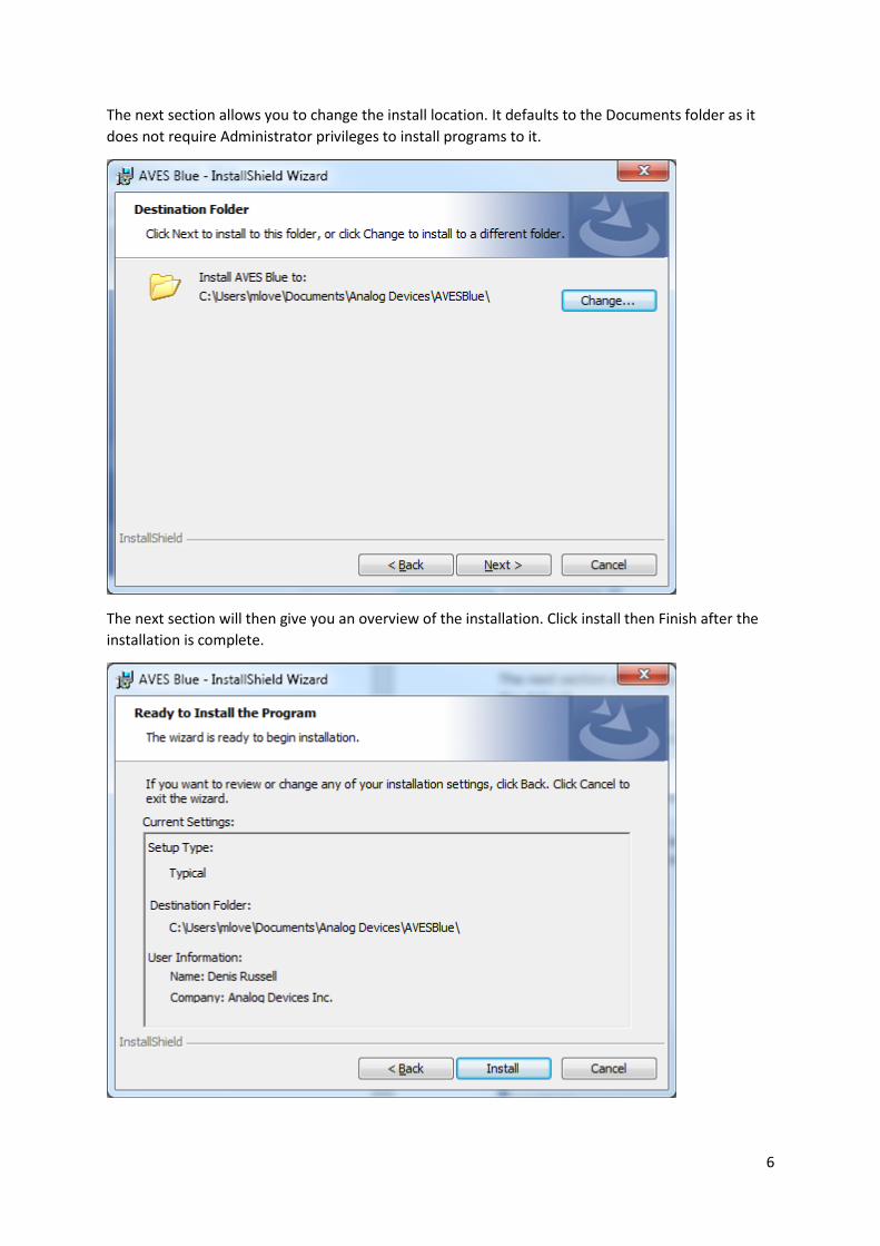
The next section allows you to change the install location. It defaults to the Documents folder as it
does not require Administrator privileges to install programs to it.
The next section will then give you an overview of the installation. Click install then Finish after the
installation is complete.
7
Installing IronPython 2.7.5 (optional) IronPython can used from within AVES for running IronPython scripts that need to get access to
AVES’ I2C connection. It is similar to how Python was used in XRC. It is an optional component and
requires you to install the IronPython interpreter to run an IronPython script.
These programs can be run outside of AVES though you will not be able to get access to AVES’ I2C
connection.
IronPython 2.7.5 can be found at developer’s website.
The main difference between IronPython and Python is that IronPython is written in .NET.
Being written in .NET means that IronPython can use any code written in a .NET language like C# and
F#. You also get access to their standard libraries on top of the Python Standard Library.
The main reason IronPython is being used is that AVES Blue is written in C# which is also a .NET
language so they are easily integrated.
Installing SDP Drivers Drivers are needed to connect to SDP based boards (e.g. ADS7 and SDP-B). The drivers can be found
at the following FTP site or at the SDP Sharepoint.
Username avesuser
Password 21GpGG4m
FTP Server ftp.analog.com
If you already have the .NET framework installed then just download SDPDrivers.exe, otherwise get
SDPDriversNET.exe which contains the .NET framework.
Installing FTDI Drivers Drivers for the FTDI chip can be found at the following FTP site or at the manufacturer’s website.
8
AVES Basics When you run AVES you’ll be presented with the connection window, covered in the next chapter.
If you double click on any tab in AVES it will be separated into a floating window. Closing the new
window will re-dock the window into the main window. If you wish to redock all of the windows at
once, click “Redock All” under the file menu.
The top of the window contains three sections which are covered in more detail later:
The file menu has controls for
o Loading board XMLs
o Loading register scripts
o Project folders (containing both of the above)
o Loading the Probe
o Re-docking all broken out tabs
The settings menu controls the persistent parameters for program operation.
The tools menu contains various high level tools available to the user.
The help window contains two controls:
o Documentation for using AVES.
o An about section describing what AVES is used for.
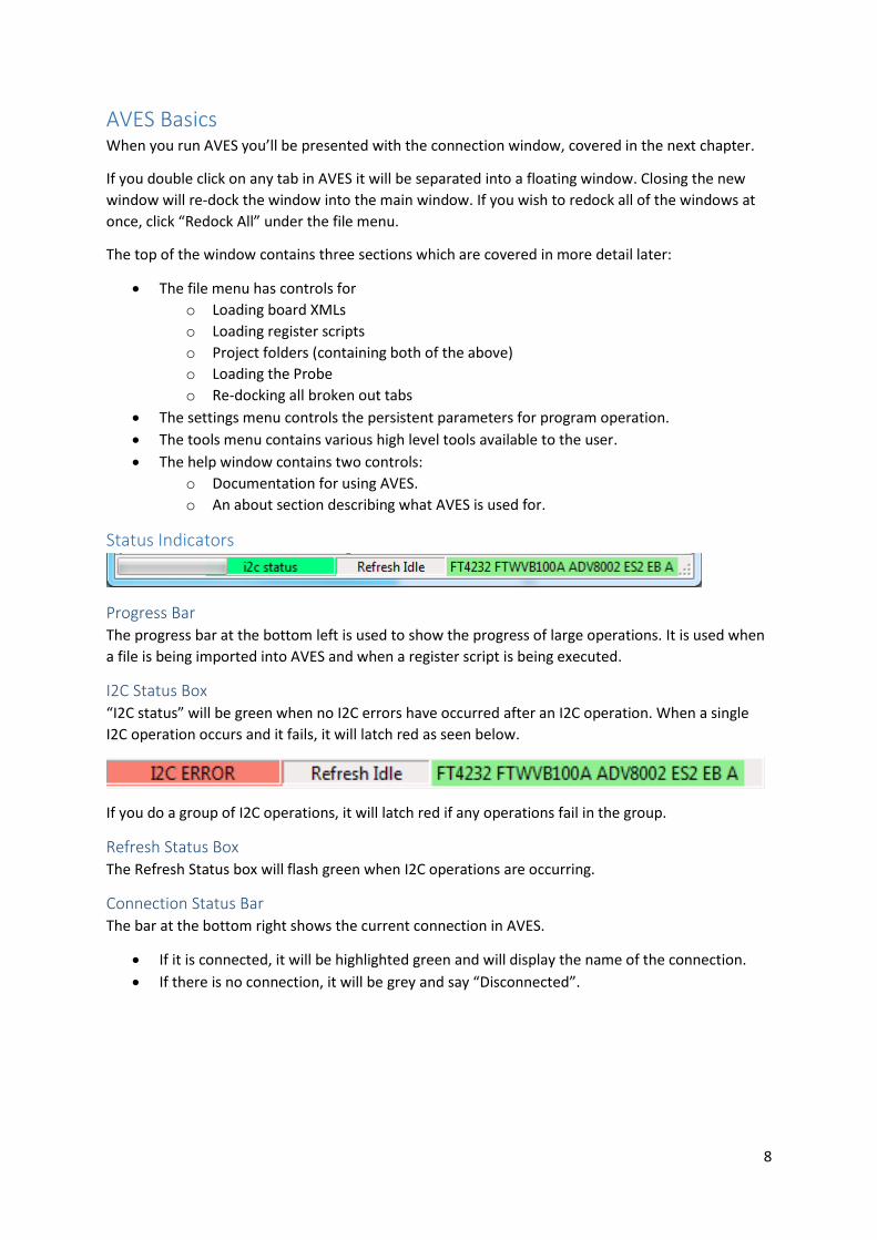
Status Indicators
Progress Bar The progress bar at the bottom left is used to show the progress of large operations. It is used when
a file is being imported into AVES and when a register script is being executed.
I2C Status Box “I2C status” will be green when no I2C errors have occurred after an I2C operation. When a single
I2C operation occurs and it fails, it will latch red as seen below.
If you do a group of I2C operations, it will latch red if any operations fail in the group.
Refresh Status Box The Refresh Status box will flash green when I2C operations are occurring.
Connection Status Bar The bar at the bottom right shows the current connection in AVES.
If it is connected, it will be highlighted green and will display the name of the connection.
If there is no connection, it will be grey and say “Disconnected”.
9
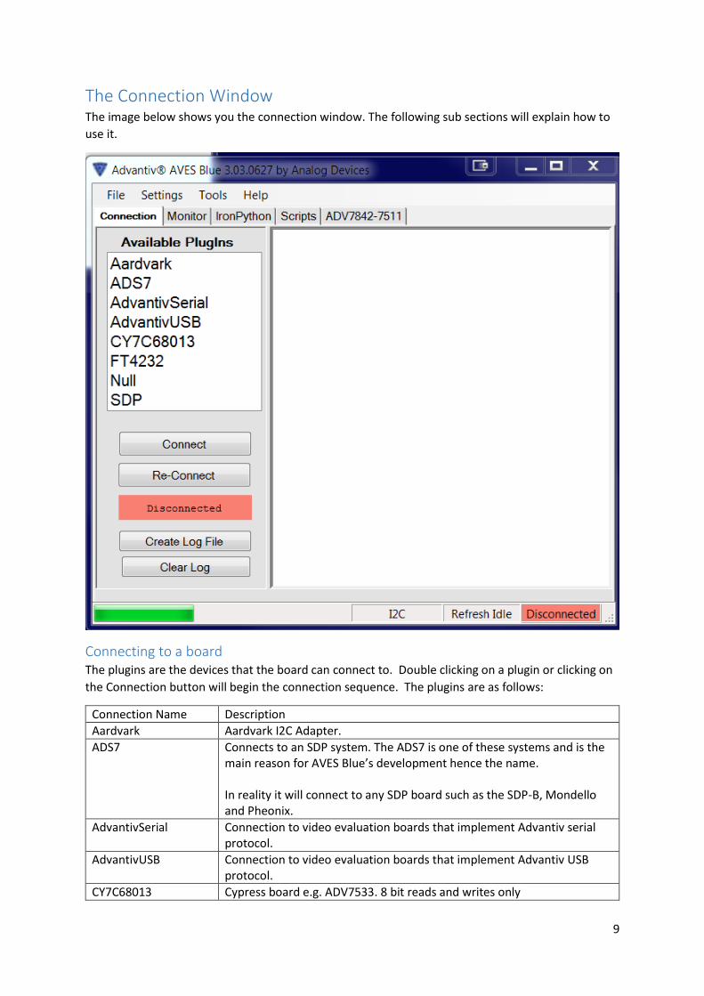
The Connection Window The image below shows you the connection window. The following sub sections will explain how to
use it.
Connecting to a board The plugins are the devices that the board can connect to. Double clicking on a plugin or clicking on
the Connection button will begin the connection sequence. The plugins are as follows:
Connection Name Description
Aardvark Aardvark I2C Adapter.
ADS7 Connects to an SDP system. The ADS7 is one of these systems and is the main reason for AVES Blue’s development hence the name. In reality it will connect to any SDP board such as the SDP-B, Mondello and Pheonix.
AdvantivSerial Connection to video evaluation boards that implement Advantiv serial protocol.
AdvantivUSB Connection to video evaluation boards that implement Advantiv USB protocol.
CY7C68013 Cypress board e.g. ADV7533. 8 bit reads and writes only
10
FT4232 FTDI.
Null Null driver used for debugging.
SDP Connecting to SDP based boards other than just the ADS7. Also allows flashing of the SDB-B firmware.
UBoot Connect to any target through UBoot application loader
Connecting to a Aardvark chip If you are connected to an Aardvark chip, all you need to do is choose the plugin, click on the
connect button and AVES will connect.
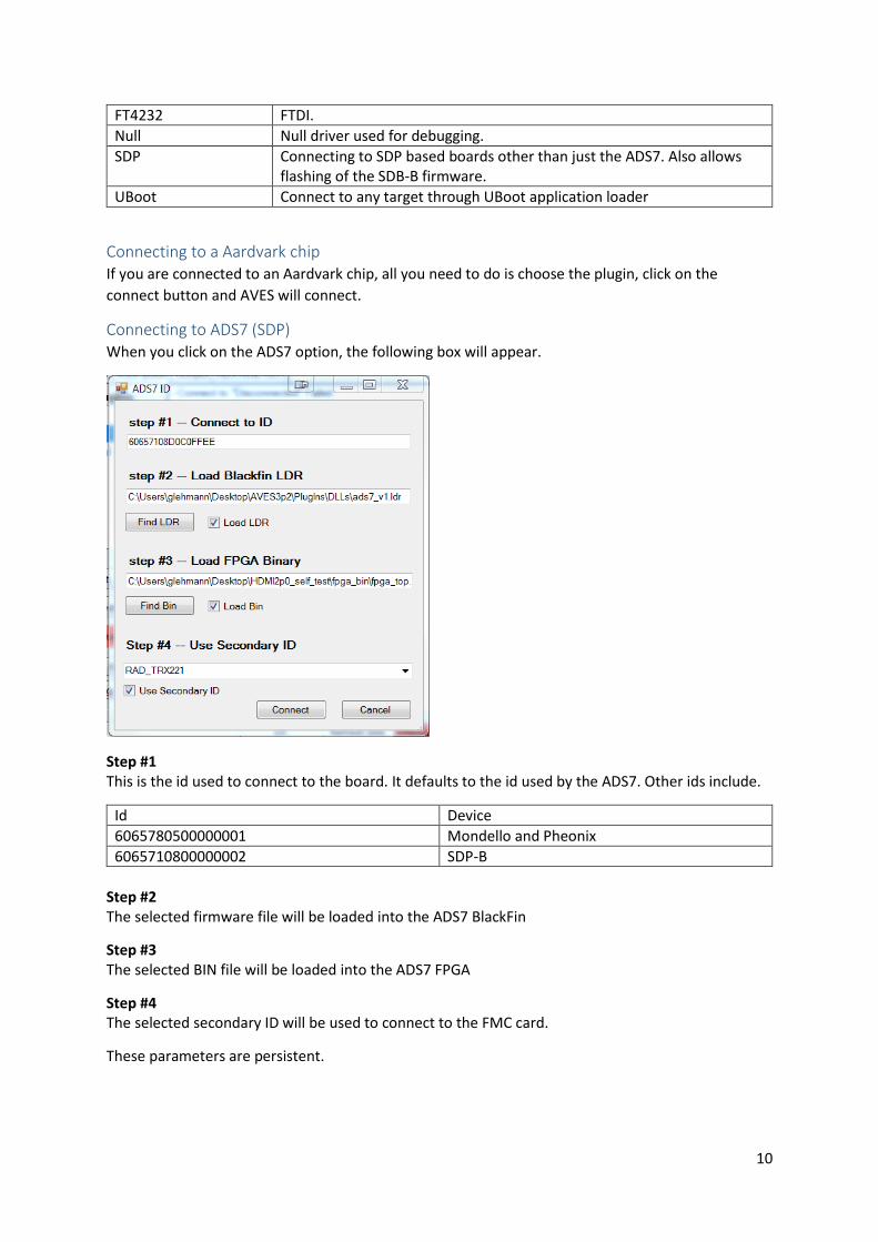
Connecting to ADS7 (SDP) When you click on the ADS7 option, the following box will appear.
Step #1 This is the id used to connect to the board. It defaults to the id used by the ADS7. Other ids include.
Id Device
6065780500000001 Mondello and Pheonix
6065710800000002 SDP-B
Step #2 The selected firmware file will be loaded into the ADS7 BlackFin
Step #3 The selected BIN file will be loaded into the ADS7 FPGA
Step #4 The selected secondary ID will be used to connect to the FMC card.
These parameters are persistent.
11
Connecting to AdvantivSerial If you are connected to an AdvantivSerial protocol board, all you need to do is choose the plugin,
click on the connect button and AVES will connect.
Connecting to a AdvantivUSB If you are connected to an AdvantivUSB protocol board , all you need to do is choose the plugin, click
on the connect button and AVES will connect.
Connecting to a Cypress chip If you are connected to a Cypress chip, all you need to do is choose the plugin, click on the connect
button and AVES will connect.
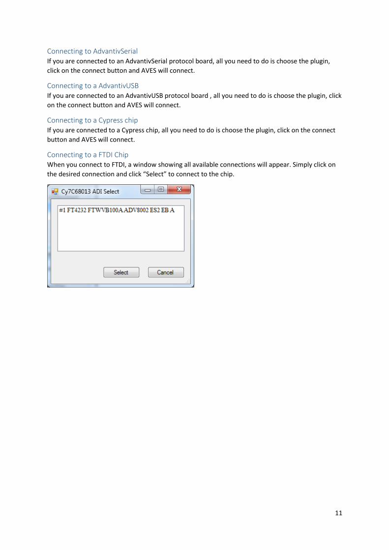
Connecting to a FTDI Chip When you connect to FTDI, a window showing all available connections will appear. Simply click on
the desired connection and click “Select” to connect to the chip.
12
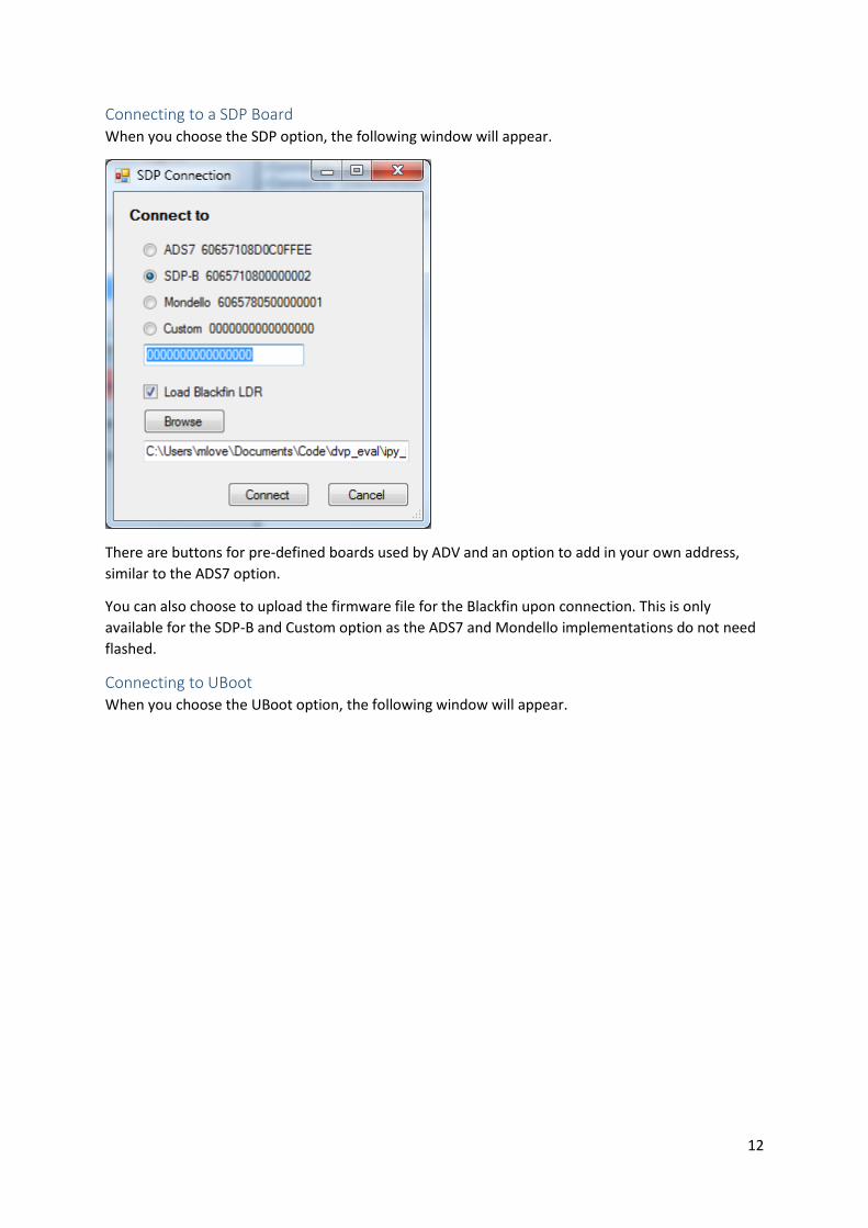
Connecting to a SDP Board When you choose the SDP option, the following window will appear.
There are buttons for pre-defined boards used by ADV and an option to add in your own address,
similar to the ADS7 option.
You can also choose to upload the firmware file for the Blackfin upon connection. This is only
available for the SDP-B and Custom option as the ADS7 and Mondello implementations do not need
flashed.
Connecting to UBoot When you choose the UBoot option, the following window will appear.

13
Step #1 Allows you to select which port you want to connect to the target with. In this case AVES Blue is
connected to the target using a serial port (COM7).
Step #2 Specifies a file which contains UBoot initialization strings that at send immediately after connection
has been established. The initialization strings can be any command from UBoot help command
however is will not be able to process responses. They are just plain writes. An example
initialization file may look like
;comments are marked with ';' as first character and are ignored
gpio set PF10
gpio clear PF10
i2c speed 100
Step #3 Has two optional action to do. ‘Connect’ will attempt to connect the target and output the target
configuration. ‘Reconnect’ will only connect to the target with no target configuration written. It is
intended to be used when a configuration has already been sent and the target is still in UBoot mode
such as what happens the ‘F7’ key is pressed to connect/disconnect AVES Blue.
Step #4 Informs you to reset the board so the UBoot driver can attempt to gain connection to the target.
When the board is reset, UBoot does some simple initialization and then begins a 5 second count
down before launching the application. The UBoot driver intercepts the count down and stops
UBoot from launching the application. Then is sends the configuration strings.
14
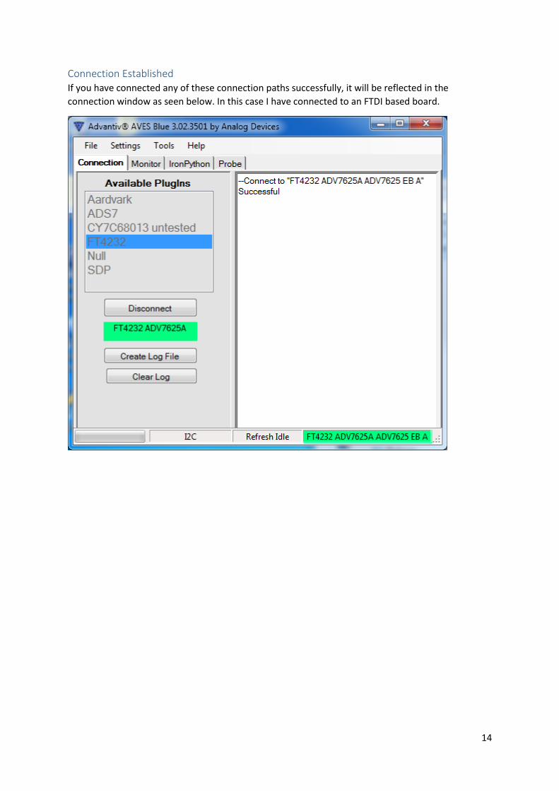
Connection Established If you have connected any of these connection paths successfully, it will be reflected in the
connection window as seen below. In this case I have connected to an FTDI based board.
15
Log file The text box to the right of the connection tab is a log of all I2C operations. I will report any
connections, reads and writes and if they failed.
You can write the log messages to a file by using the “Select Log File” button. This will open a file
viewer to save the log messages to.
Clearing the log will not affect a log file if you have one open.
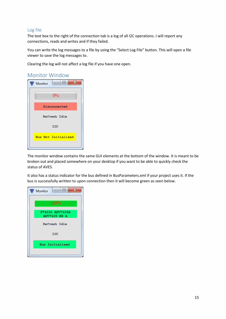
Monitor Window
The monitor window contains the same GUI elements at the bottom of the window. It is meant to be
broken out and placed somewhere on your desktop if you want to be able to quickly check the
status of AVES.
It also has a status indicator for the bus defined in BusParameters.xml if your project uses it. If the
bus is successfully written to upon connection then it will become green as seen below.
16
The File Menu
Project Opens a folder viewer and the user chooses a project folder.
A project folder contains board XMLs, register scripts, hints files etc. It will load them all depending
on the preference settings.
Device Used to import individual board XMLs into AVES. It will open a file viewer and ask you to load an
XML.
ScriptX This is used to load Register Scripts into AVES. A file viewer is opened to choose the script files.
If no register scripts were previously opened, the Scripts tab will be added. This is covered in more
detail in the Scripts section.
Probe This loads the probe which is used to interact with individual registers. It is covered in more detail in
the probe section.
IronPython This reveals the IronPython window. It lets you run scripts using the IronPython language. The scripts
have access to AVES’ I2C connection
Re-dock All This re-docks all undocked tabs back into the main program.
Remove Active Project Removes the Project folder tab the AVES window.
Remove Active Device Removes the Device tab the AVES window.
Exit Closes the program. Identical to clicking the red button at the top right of the window.
17
Settings
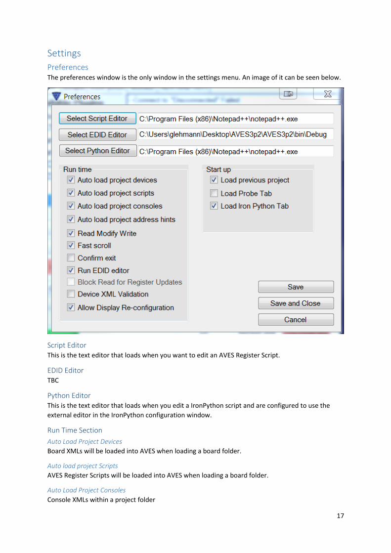
Preferences The preferences window is the only window in the settings menu. An image of it can be seen below.
Script Editor This is the text editor that loads when you want to edit an AVES Register Script.
EDID Editor TBC
Python Editor This is the text editor that loads when you edit a IronPython script and are configured to use the
external editor in the IronPython configuration window.
Run Time Section
Auto Load Project Devices
Board XMLs will be loaded into AVES when loading a board folder.
Auto load project Scripts
AVES Register Scripts will be loaded into AVES when loading a board folder.
Auto Load Project Consoles
Console XMLs within a project folder
18
Auto Load Project Address Hints
This will parse the hints files in the board XMLs and add them to the register maps.
Read Modify Write
After a write, a read is performed on the register.
Fast Scroll
Typically AVES will refresh the register maps as you scroll through it. This comes with a large
performance penalty. Fast scroll disables refreshing until after you have stopped scrolling.
Confirm Exit
If this is enabled, a popup will be created when exiting AVES to confirm you want to quit.
Run EDID Editor
TBC
Block Read for Register Updates
This makes AVES read all of the visible registers at one time instead of one at a time when refreshing
a register map. Currently disabled.
Device XML Validation
Upon loading a device xml, AVES will validate that it meets a standard laid out for the device XMLs.
Allow Display Re-Configuration
Allows the user to custom which tabs are hidden.
Start up
Load Previous Project
If this is enabled, all boards that were loaded when you closed AVES will be reloaded the next time
you open AVES.
Load Probe Tab
Makes the Probe tab visible on start-up.
Load IronPython Tab
Makes the IronPython tab visible on start-up.

19
Bus Configurator Current evaluation boards only map chip I2C addressing to unique addresses on the I2C bus so
multiple instances of the same chip do not collide in the address space. Future boards will multiple
instances of the same chip mapped to the same I2C address space or possibly different I2C busses or
using chip selects. The problem is then how do we access all the different chips with overlapping I2C
maps on different busses and with chip selects.
The Bus Configurator is one solution to this problem. Basically within the application code, the
application will implement virtual bus switches or chip selects. When I2C commands are sent the
application will intercept the commands addressed to the virtual I2C slave in the code and set the
chip selects or bus switches accordingly. All non-virtual I2C transactions will be sent the targeted
chip selected by the virtual transactions.
The upside to this approach is we will now be able to access multiple instances of the same chip
sitting at the same address on the I2C bus and handle chip selects. The down side is that it requires
the application code to implement virtual I2C slave device and will only work with AdvantivSerial,
AdvantivUSB or ADS7 drivers and it must be part of a project.
Below is the Bus Configuration window.
The ‘Default’ writes occur only when the connection is initially made.
The hierarchical writes occur whenever the program attempts to access a different chip instance.
The chip instances are identified as the target name and must match the device name in the tabs
within the project. When a new chip is accessed the ‘Writes’ will be sent before the first transaction
to the target. All subsequent writes to the chip instance will not be prefixed with the ‘Writes’. Every
time the program switches to another chip instance the ‘Writes’ will be send first and only once.
In the above picture, there are two targets, instance 0 and instance 1. The project file must contain
two copies of the same device xml file except the names have been changed to reflect the different
instances. The associated ‘Writes’ are the I2C transactions that need to occur to access the specific
instance.
Commands can be 2 or 3 bytes long with multiple commands separated by ‘;’.
The ‘Save and Close’ button saves the configuration in the project directory. This saved file is
automatically loaded when the project is opened.
20
The ‘Validate’ button just validates that the transactions are in the correct format.
All this works with the null driver if you want to experiment with the configuration before having the
target application virtual I2C slaves ready.
The Bus Configuration works with the Probe and Device tabs. It will not work with script files or
Python code. Python and scripts must implement their own writes to the virtual slave. These must
be three byte transactions.
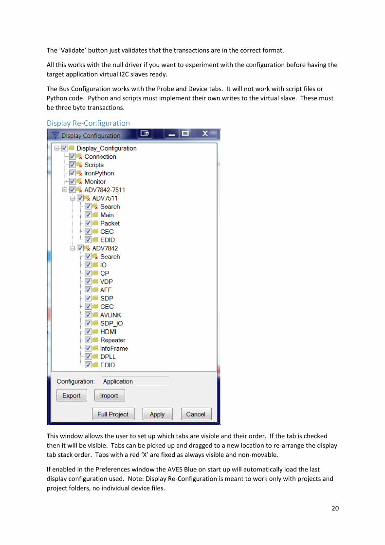
Display Re-Configuration
This window allows the user to set up which tabs are visible and their order. If the tab is checked
then it will be visible. Tabs can be picked up and dragged to a new location to re-arrange the display
tab stack order. Tabs with a red ‘X’ are fixed as always visible and non-movable.
If enabled in the Preferences window the AVES Blue on start up will automatically load the last
display configuration used. Note: Display Re-Configuration is meant to work only with projects and
project folders, no individual device files.
21
Export
Saves the configuration to an XML style file.
Import
Reads a previously stored configuration
Full Project
Closes this window and restores the project display to its original display configuration, all tabs
shown and in their original order.
Apply
Closes this window and sets the project display to the configuration as shown in this window
22
Tools
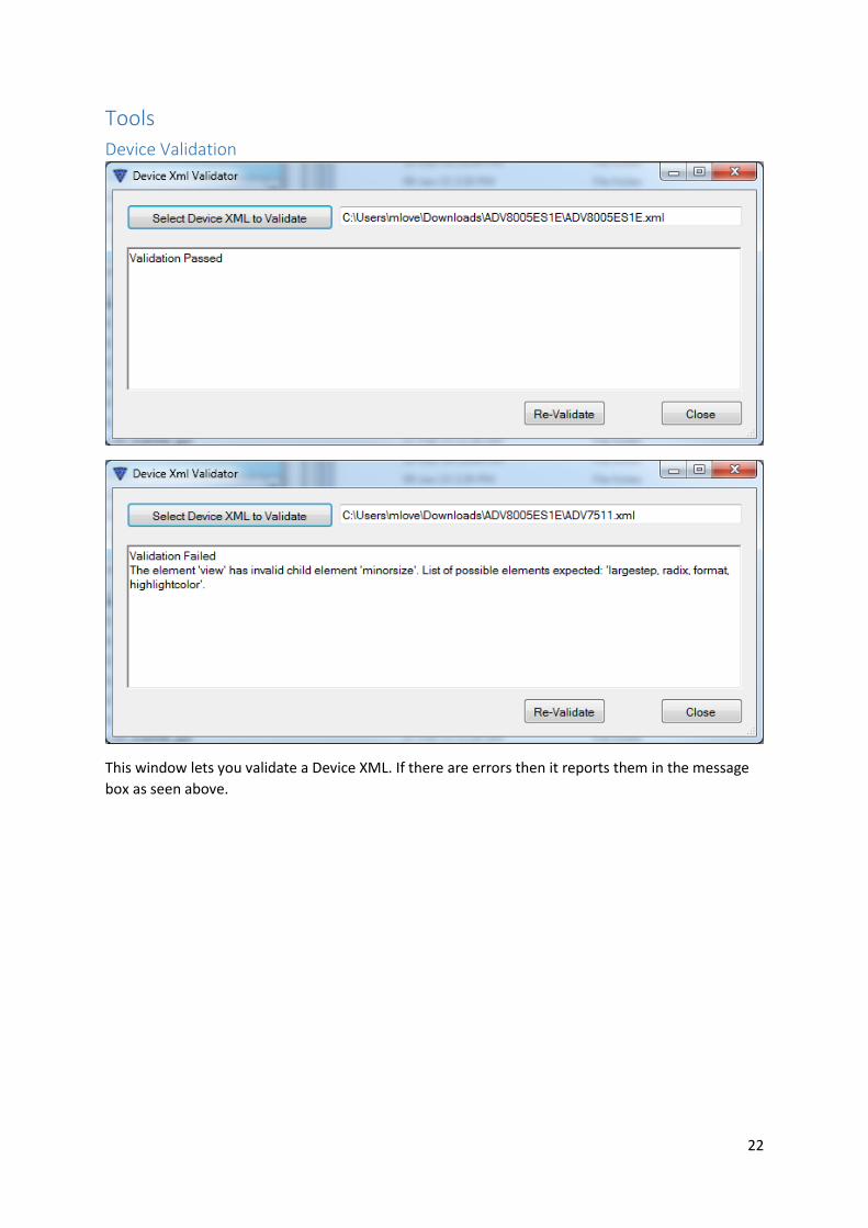
Device Validation
This window lets you validate a Device XML. If there are errors then it reports them in the message
box as seen above.
23
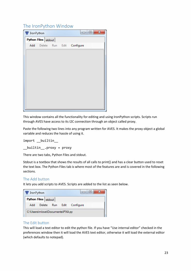
The IronPython Window
This window contains all the functionality for editing and using IronPython scripts. Scripts run
through AVES have access to its I2C connection through an object called proxy.
Paste the following two lines into any program written for AVES. It makes the proxy object a global
variable and reduces the hassle of using it.
import __builtin__
__builtin__.proxy = proxy
There are two tabs, Python Files and stdout.
Stdout is a textbox that shows the results of all calls to print() and has a clear button used to reset
the text box. The Python Files tab is where most of the features are and is covered in the following
sections.
The Add button It lets you add scripts to AVES. Scripts are added to the list as seen below.
The Edit button This will load a text editor to edit the python file. If you have “Use internal editor” checked in the
preferences window then it will load the AVES text editor, otherwise it will load the external editor
(which defaults to notepad).
24
Running Files Once a python script is added, run the file by either double clicking on it or by clicking on the file
name and press the run button.
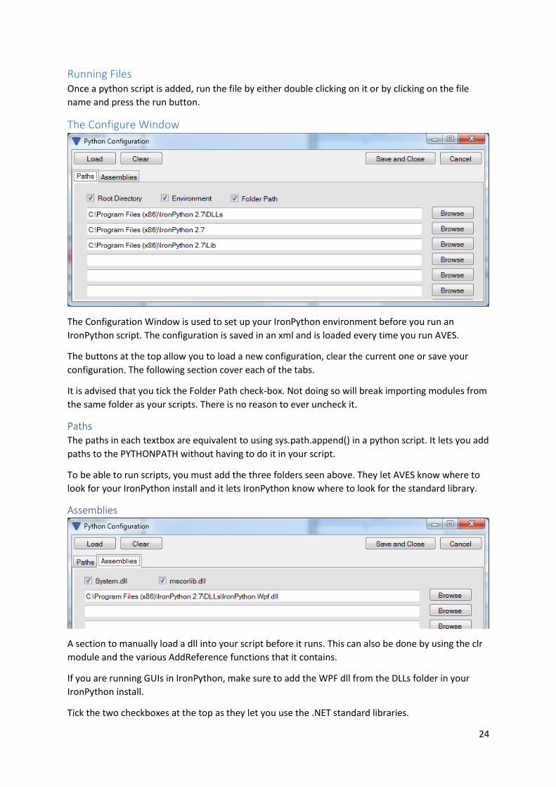
The Configure Window
The Configuration Window is used to set up your IronPython environment before you run an
IronPython script. The configuration is saved in an xml and is loaded every time you run AVES.
The buttons at the top allow you to load a new configuration, clear the current one or save your
configuration. The following section cover each of the tabs.
It is advised that you tick the Folder Path check-box. Not doing so will break importing modules from
the same folder as your scripts. There is no reason to ever uncheck it.
Paths The paths in each textbox are equivalent to using sys.path.append() in a python script. It lets you add
paths to the PYTHONPATH without having to do it in your script.
To be able to run scripts, you must add the three folders seen above. They let AVES know where to
look for your IronPython install and it lets IronPython know where to look for the standard library.
Assemblies
A section to manually load a dll into your script before it runs. This can also be done by using the clr
module and the various AddReference functions that it contains.
If you are running GUIs in IronPython, make sure to add the WPF dll from the DLLs folder in your
IronPython install.
Tick the two checkboxes at the top as they let you use the .NET standard libraries.
25
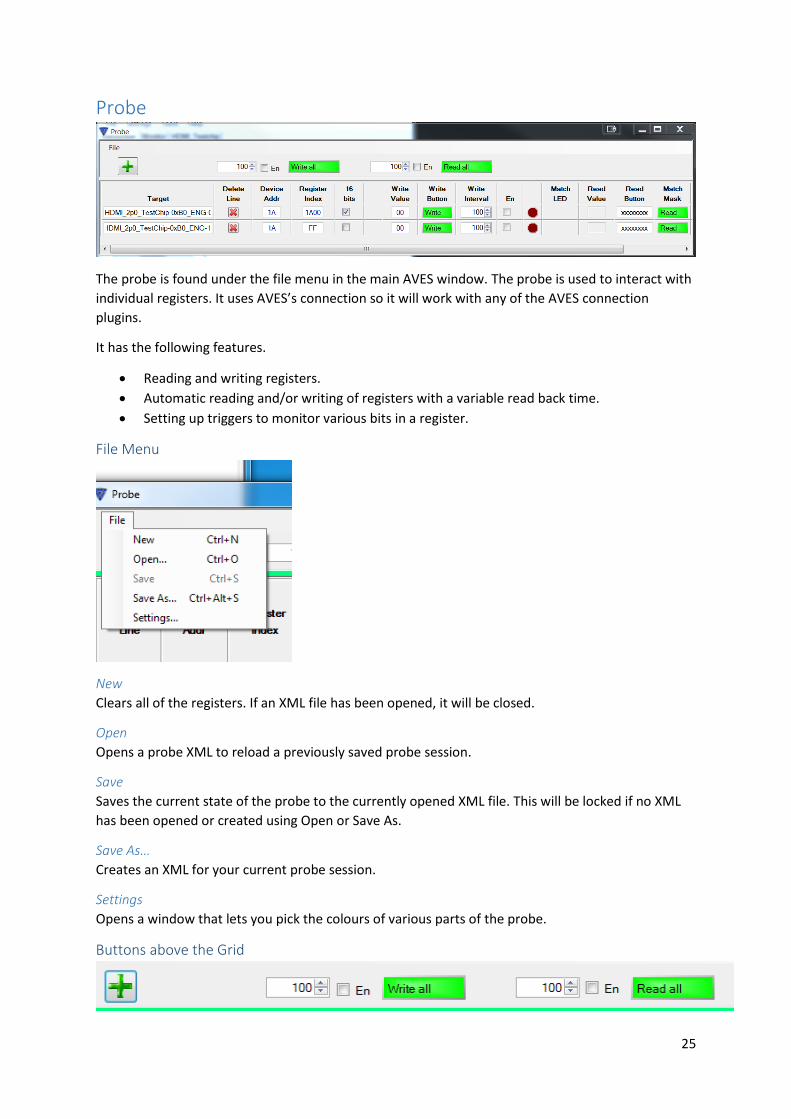
Probe
The probe is found under the file menu in the main AVES window. The probe is used to interact with
individual registers. It uses AVES’s connection so it will work with any of the AVES connection
plugins.
It has the following features.
Reading and writing registers.
Automatic reading and/or writing of registers with a variable read back time.
Setting up triggers to monitor various bits in a register.
File Menu
New
Clears all of the registers. If an XML file has been opened, it will be closed.
Open
Opens a probe XML to reload a previously saved probe session.
Save
Saves the current state of the probe to the currently opened XML file. This will be locked if no XML
has been opened or created using Open or Save As.
Save As…
Creates an XML for your current probe session.
Settings
Opens a window that lets you pick the colours of various parts of the probe.
Buttons above the Grid
26
Plus Button
Adds another register to the grid of registers.
Textbox next to Write All
The time in milliseconds for each write when repetitive write mode is on.
En Checkbox next to Write All
Enables continuous writes of the values in every “Write Value” field to its corresponding register.
Write All
This writes each of the values in “Write Value” field to its corresponding register.
Textbox next to Read All
The time in milliseconds for each read when repetitive write mode is on.
En Checkbox next to Read All
Enables continuous reads of every register.
Write All
Reads the value of every register in the probe.
27
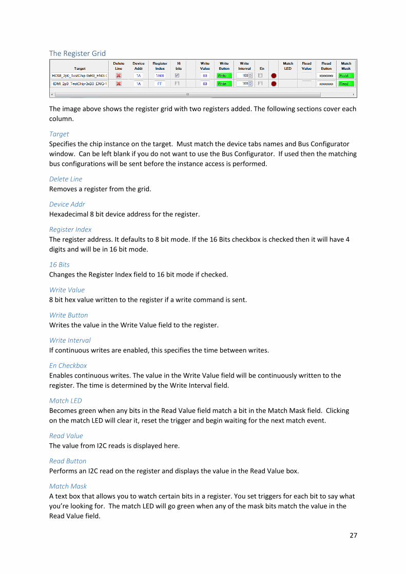
The Register Grid
The image above shows the register grid with two registers added. The following sections cover each
column.
Target
Specifies the chip instance on the target. Must match the device tabs names and Bus Configurator
window. Can be left blank if you do not want to use the Bus Configurator. If used then the matching
bus configurations will be sent before the instance access is performed.
Delete Line
Removes a register from the grid.
Device Addr
Hexadecimal 8 bit device address for the register.
Register Index
The register address. It defaults to 8 bit mode. If the 16 Bits checkbox is checked then it will have 4
digits and will be in 16 bit mode.
16 Bits
Changes the Register Index field to 16 bit mode if checked.
Write Value
8 bit hex value written to the register if a write command is sent.
Write Button
Writes the value in the Write Value field to the register.
Write Interval
If continuous writes are enabled, this specifies the time between writes.
En Checkbox
Enables continuous writes. The value in the Write Value field will be continuously written to the
register. The time is determined by the Write Interval field.
Match LED
Becomes green when any bits in the Read Value field match a bit in the Match Mask field. Clicking
on the match LED will clear it, reset the trigger and begin waiting for the next match event.
Read Value
The value from I2C reads is displayed here.
Read Button
Performs an I2C read on the register and displays the value in the Read Value box.
Match Mask
A text box that allows you to watch certain bits in a register. You set triggers for each bit to say what
you’re looking for. The match LED will go green when any of the mask bits match the value in the
Read Value field.

28
The settings are as follows.
X means you don’t care about the bit.
1 will light up the match LED when the bit goes high.
0 will light up the match LED when the bit goes low.
Read Interval
If continuous reads are enabled, this specifies the time between each read.
En Checkbox
Enables continuous reads for the register. It will continuously read the register and write the value
to the Read Value field.
29
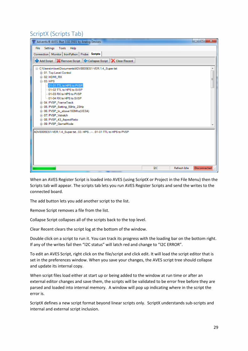
ScriptX (Scripts Tab)
When an AVES Register Script is loaded into AVES (using ScriptX or Project in the File Menu) then the
Scripts tab will appear. The scripts tab lets you run AVES Register Scripts and send the writes to the
connected board.
The add button lets you add another script to the list.
Remove Script removes a file from the list.
Collapse Script collapses all of the scripts back to the top level.
Clear Recent clears the script log at the bottom of the window.
Double click on a script to run it. You can track its progress with the loading bar on the bottom right.
If any of the writes fail then “I2C status” will latch red and change to “I2C ERROR”.
To edit an AVES Script, right click on the file/script and click edit. It will load the script editor that is
set in the preferences window. When you save your changes, the AVES script tree should collapse
and update its internal copy.
When script files load either at start up or being added to the window at run time or after an
external editor changes and save them, the scripts will be validated to be error free before they are
parsed and loaded into internal memory. A window will pop up indicating where in the script the
error is.
ScriptX defines a new script format beyond linear scripts only. ScriptX understands sub-scripts and
internal and external script inclusion.
30
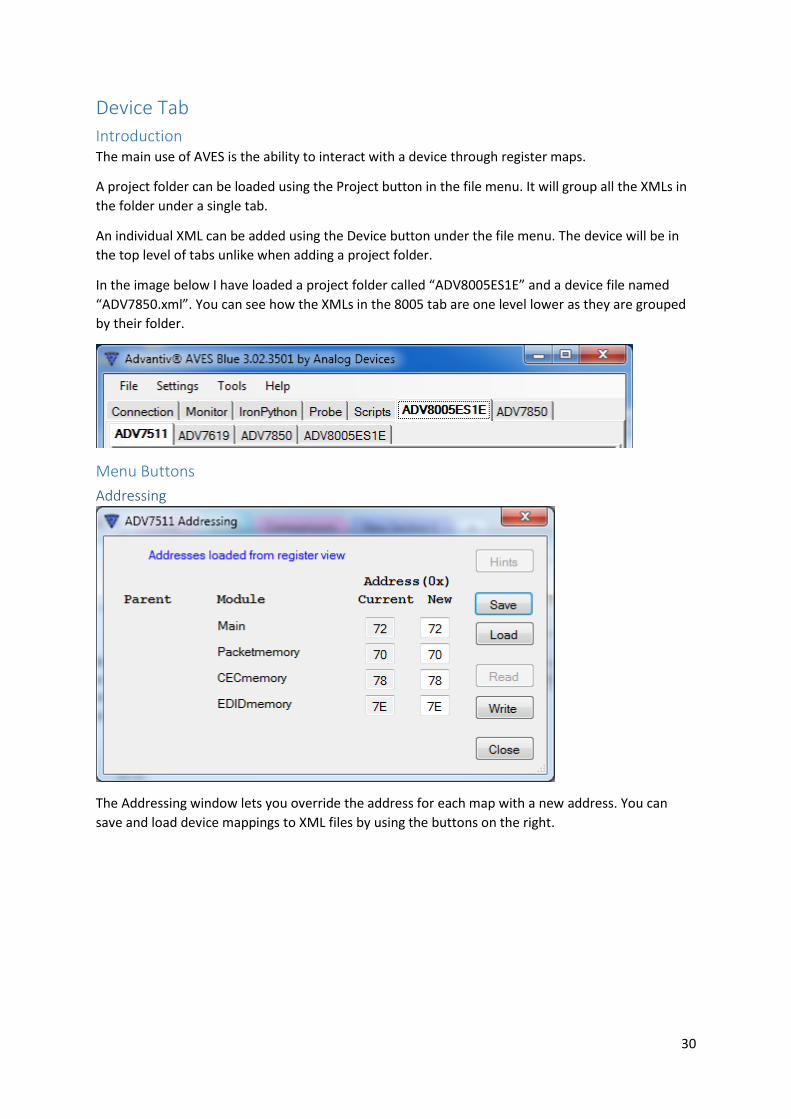
Device Tab
Introduction The main use of AVES is the ability to interact with a device through register maps.
A project folder can be loaded using the Project button in the file menu. It will group all the XMLs in
the folder under a single tab.
An individual XML can be added using the Device button under the file menu. The device will be in
the top level of tabs unlike when adding a project folder.
In the image below I have loaded a project folder called “ADV8005ES1E” and a device file named
“ADV7850.xml”. You can see how the XMLs in the 8005 tab are one level lower as they are grouped
by their folder.
Menu Buttons
Addressing
The Addressing window lets you override the address for each map with a new address. You can
save and load device mappings to XML files by using the buttons on the right.

31
Consoles Consoles are simplified version of the probe. Consoles allow you to monitor or control register fields
in a device map. Consoles can be a user force read or periodically read fields. You can create
custom consoles for each device that let you monitor registers from that device. You cannot mix
registers from multiple devices in the same console window.
Loading a Console
Some consoles are stored in device XMLs. They are also read only. The image below shows that our
XML for the ADV7511 came with 3 consoles. Loading on of them will add another tab to the
ADV7511 section.
You can create your own console by pressing Create New seen in the image above. A popup is
created to give the console a name. A new tab is created next to the register map tabs with the
console name. In this example I will create a new console call “Example Console”.
As you can see, a new tab called “Console: Example Console” has been created and it is blank.
32
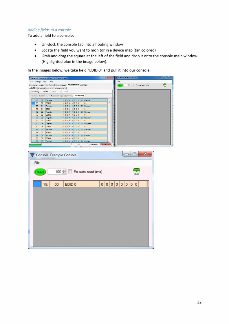
Adding fields to a console
To add a field to a console:
Un-dock the console tab into a floating window
Locate the field you want to monitor in a device map (tan colored)
Grab and drag the square at the left of the field and drop it onto the console main window.
(Highlighted blue in the image below).
In the images below, we take field “EDID 0” and pull it into our console.

33
The item on in the console window
Read does a read of all visible fields in the console.
The field next to the read button is the time in milliseconds for the continuous read mode.
The checkbox to the right lets you turn on continuous read mode.
The Bin icon lets you remove fields by dragging the square at the left of the field into the bin.
Capture The capture command lets you take a register dump of one or all maps. Note that all captured
registers are refreshed before the capture takes place.
It loads the following window.
If you choose script mode, it outputs the reads in the form of a register script so the file can be
loaded into AVES again if needed.
Byte mode just writes all the values of the registers to the file. It does not write the device address
or register address to the file.
Bytes per line just displays how many reads will be put on a single line.
The comments checkbox means that the device name and a timestamp will be put at the top of a
file.
EDID TBC
Read This reads all registers that are visible on the monitor. This can also be triggered by pressing the F5
key.
34
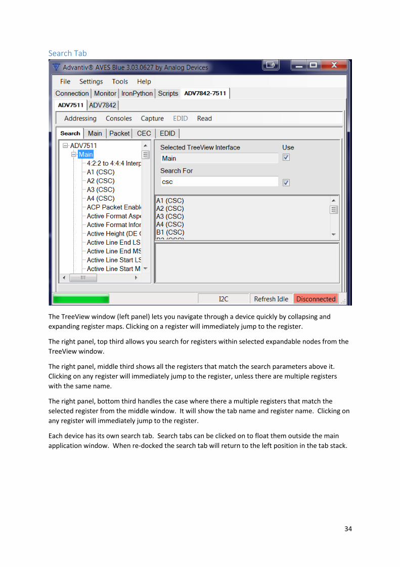
Search Tab
The TreeView window (left panel) lets you navigate through a device quickly by collapsing and
expanding register maps. Clicking on a register will immediately jump to the register.
The right panel, top third allows you search for registers within selected expandable nodes from the
TreeView window.
The right panel, middle third shows all the registers that match the search parameters above it.
Clicking on any register will immediately jump to the register, unless there are multiple registers
with the same name.
The right panel, bottom third handles the case where there a multiple registers that match the
selected register from the middle window. It will show the tab name and register name. Clicking on
any register will immediately jump to the register.
Each device has its own search tab. Search tabs can be clicked on to float them outside the main
application window. When re-docked the search tab will return to the left position in the tab stack.

35
Register Map
The above image is a register map. The table below describes each column does.
Column Description
1 A grab point to drag the field to a console window
2 Device Address.
3 Register Address
4 The name of the field.
5-12 The bits of each field. If it is white then it can be written to. Clicking the bit will change it from a 0 to 1 and vice versa. The blue row represents the total value of the tan fields below it. The number next to it is the value in hex and can be changed.
13 The total value of the register.
14 The dropdowns say what the value of the field means. Clicking on the drop down lets you change the value of the field. Some fields span multiple registers. When these field are clicked on, AvesBlue will pop up a floating ‘MetaField’ editor.
36
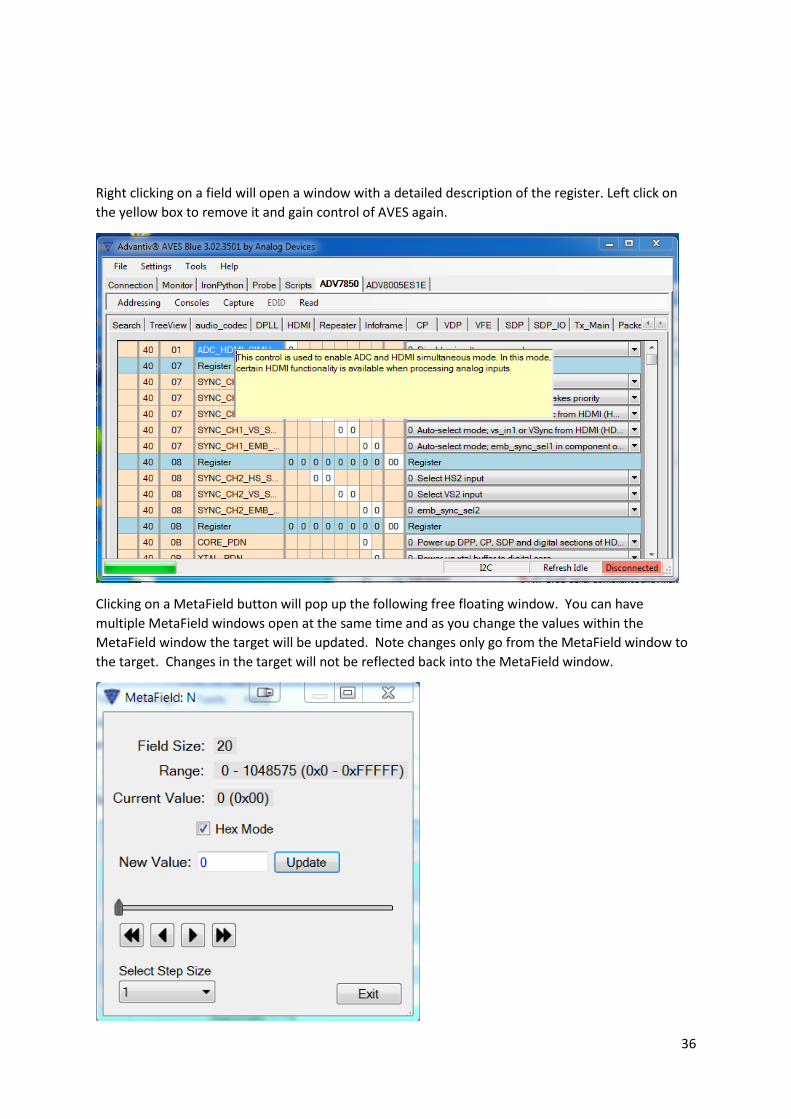
Right clicking on a field will open a window with a detailed description of the register. Left click on
the yellow box to remove it and gain control of AVES again.
Clicking on a MetaField button will pop up the following free floating window. You can have
multiple MetaField windows open at the same time and as you change the values within the
MetaField window the target will be updated. Note changes only go from the MetaField window to
the target. Changes in the target will not be reflected back into the MetaField window.
37
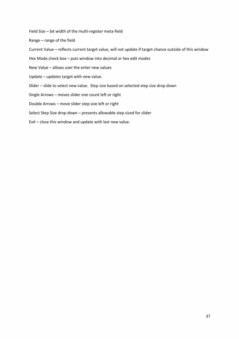
Field Size – bit width of the multi-register meta-field
Range – range of the field
Current Value – reflects current target value, will not update if target chance outside of this window
Hex Mode check box – puts window into decimal or hex edit modes
New Value – allows user the enter new values
Update – updates target with new value.
Slider – slide to select new value. Step size based on selected step size drop down
Single Arrows – moves slider one count left or right
Double Arrows – move slider step size left or right
Select Step Size drop down – presents allowable step sized for slider
Exit – close this window and update with last new value.

38
FAQ
How do I delete a Project Tab? Use Files->Remove Active Project or change preferences so the previous project is not reloaded
when AVES is started.
Does the Register Dump (capture button) do a read-back from the device? Yes, it reads all the registers you are capturing immediately before storing the register values into a
file.
How do I add a field to the console window? Make sure that the console window is undocked. Grab and drag the left most cell from a device map
field (tan coloured) and drop it into the console window.
How do I know when an I2C operation has failed? The “I2C status” bar at the bottom of the window will latch red and say “I2C ERROR” as seen below.
Can I have one project connected to one connection and another project with a
different connection? Yes but with separate instances of AVES Blue i.e. two programs running independently.
What is for Null connection for? It’s just a dummy driver that is used to view register maps without having it constantly latch red
from “read fails.” Used for program testing and debug purposes
Can I create my own plug-in connections? Yes, the plug-in interface defines about 12 methods that need to be implemented to use different
I2C hardware. Example source code and dll’s can be provided upon request.
How do I re-dock all of the tabs? Click the Re-dock all button below the file menu.
What is the probe function for? It is used for debugging or checking particular registers. It supports continuous reading and writing
of a register at any address on the I2C bus and you can set up triggers so the GUI will highlight when
a condition has been met.
My USB chip is listed in AVES but isn’t working, why? Do you have the required drivers? Look at the Drivers section to find them.
What is the difference between Project and Device? Project loads a folder containing board XMLs, register scripts and console scripts. Device just loads a
device XML. A board XML can be located anywhere in the file system
Why is the ScriptX button disabled? Because a script has already been loaded. The scripts tab is already visible.
39
What is the IronPython tab for? It is a plugin for developers. It allows you to run small scripts to automate certain actions using the
connection already established by the main program.
What are the installation requirements for AVES? Windows 7 and beyond with at least 4GB RAM.
Do I need to uninstall a previous version of AVES (e.g. AVES3) if I am installing AVES
Blue? No, AVES Blue is installed separately from previous versions. They can exist side by side.
Does uninstalling AVES Blue delete old user files? No, previous configurations for AVES Blue and the IronPython section will be retained across
installations.
40
References
[1] GuenterL, “Advantiv™ Video Evaluation Software,” Analog Devices International, 11 December
2012. [Online]. Available: https://ez.analog.com/docs/DOC-1789. [Accessed 6 February 2015].
[2] Analog Devices International, “System Demonstration Platform (SDP),” Analog Devices
International, 2015. [Online]. Available: http://www.analog.com/en/system-demonstration-
platform/evaluation/index.html. [Accessed 6 Feburary 2015].
[3] Future Technology Devices International, “FTDI Chip Home Page,” Future Technology Devices
International, 2015. [Online]. Available: http://www.ftdichip.com/. [Accessed 6 February 2015].
[4] IronPython Team, “IronPython,” 06 December 2014. [Online]. Available: http://ironpython.net/.
[Accessed 6 Febraury 2015].
[5] Microsoft, “What is a DLL?,” 4 December 2007. [Online]. Available:
http://support.microsoft.com/kb/815065. [Accessed 6 February 2015].
[6] M. Rouse, “XML (Extensible Markup Language) definition,” 12 December 2014. [Online].
Available: http://searchsoa.techtarget.com/definition/XML. [Accessed 6 February 2015].
[7] i2c-bus.org, “I2C-Bus: What's that?,” i2c-bus.org, [Online]. Available: http://www.i2c-bus.org/.
[Accessed 6 Feburary 2015].