gigabox centrifugal fans product-specific information
TRANSCRIPT
GigaBox centrifugal fansProduct-specific information
n Application Multifunctional fan box for the
transportation of medium to large volume flows against high resistances in ventilation sys-tems of all kinds. The compact frame design and easy-to-in-stall accessories allow variable and thus optimal adaptation to structural conditions by simply repositioning the casing panels.
n GB T120 and GB EC T120 The GigaBox T120 types are
designed for the delivery of con-taminated, humid and hot air up to max. 120 °C, e.g. as extract air fans in commercial kitchens and many process technology applications. GigaBox T120 types with EC drive technology are optionally available for ener-gy-saving applications and the lowest operating costs.
n GB EC GigaBox types with EC drive
technology are optionally avail-able for energy-saving applica-tions and the lowest operating costs.
n Casing Self-supporting frame construc-
tion made of aluminium hollow profiles. Double-walled, 20 mm thick side panels made of gal-vanised steel sheet, sound and heat insulated by non-flammable mineral wool lining. Nozzle on inlet side for optimal inflow as well as connectors and flexible connecting sleeve for duct connection. Moulded part (square to round) on outlet side for low-loss outflow and flexible connecting sleeve to prevent structure-borne noise transmis-sion. The flexible connecting sleeves included in the scope of delivery correspond to a max. permissible air flow temperature of +70 °C or +120 °C for types
GB T120 and GB EC T120. Simple positioning with crane hook as standard.
n The drive motor is located out-side of the air flow for GB T120 and GB EC T120. The thermally insulated partition is also the support plate for the motor-im-peller unit and it can be com-pletely removed for inspection without dismantling the system components.
n Power controln GB and GB T120 All types (excluding GBD 630/4
T120, GBD 710/4 and GBD 710/4 T120) are speed-control-lable using 5-step transformer or electronic controllers. The 3~ GB types can also be inexpen-sively operated at two speeds using a Y/s switch (accessory DS 2 or motor protection circuit breaker M4).
Performance levels are shown in the performance diagram. Control by means of frequency converter with integrated sine filter (FU-BS, accessories) is possible for 3~ types; GBD 630/4 T120, GBD 710/4 and GBD 710/4 T120 can only be controlled by frequency convert-er FU-BS.
n GB EC and GB EC T120 All EC types have continuously
variable speed control via speed potentiometer. Control is also possible via three level switch or continuously variable via univer-sal control system or electronic differential pressure/temperature controller. Performance levels are shown on the characteristic curve as examples.
n Positioning, installationn GB and GB EC Any installation position and flex-
ible installation due to five possi-
ble outlet directions of the outlet fitting. Removable side panels allow inspection access from all sides.
n GB T120 and GB EC T120 Installation position with con-
densate drain below. Flexible installation due to three possible centrifugal outlet directions of the outlet fitting. Inspection cov-er with handle, easily removable for cleaning and maintenance. Simple positioning with crane hook as standard.
The transmission of structure- borne noise to buildings is min-
imised by vibration dampers (type SDD-U, accessories). The transmission of vibrations to the duct sys tem is prevented by the standard flexible connecting sleeves.
n Impeller Free-running high performance
centrifugal impeller with back-ward curved plastic blades (nominal size 250 made of steel) on galvanised steel plate, directly driven. Series GB EC, GB from nominal size 500 and GB T120 and GB EC T120 with aluminium impellers. Energy-
efficient with low noise emission. Dynamically balanced together with the motor in accordance with DIN ISO 21940-11 – quality grade 6.3 or 2.5.
n Driven GB and GB T120 IEC standard motor or mainte-
nance-free external rotor motor in protection category IP 54 or 44. Thermal overload protection through thermal contacts in the winding. Suitable for continuous operation S1. Insulation class F. The ball bearings have a suffi-cient lubricant supply for their service life).
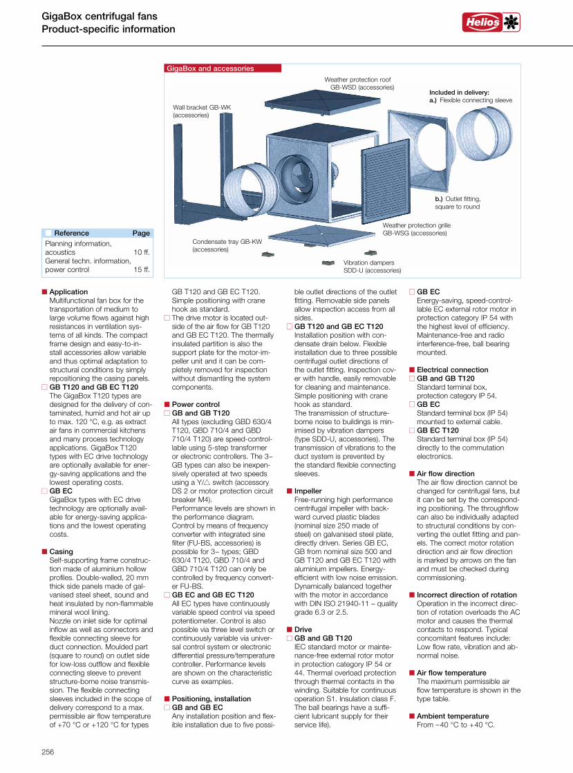
Condensate tray GB-KW (accessories)
Weather protection roof GB-WSD (accessories)
Weather protection grille GB-WSG (accessories)
Wall bracket GB-WK (accessories)
GigaBox and accessories
Included in delivery: a.) Flexible connecting sleeve
Vibration dampers SDD-U (accessories)
b.) Outlet fitting, square to round
n GB EC Energy-saving, speed-control-
lable EC external rotor motor in protection category IP 54 with the highest level of efficiency. Maintenance-free and radio interference-free, ball bearing mounted.
n Electrical connectionn GB and GB T120 Standard terminal box,
protection category IP 54.n GB EC Standard terminal box (IP 54)
mounted to external cable.n GB EC T120 Standard terminal box (IP 54)
directly to the commutation electronics.
n Air flow direction The air flow direction cannot be
changed for centrifugal fans, but it can be set by the correspond-ing positioning. The throughflow can also be individually adapted to structural conditions by con-verting the outlet fitting and pan-els. The correct motor rotation direction and air flow direction is marked by arrows on the fan and must be checked during commissioning.
n Incorrect direction of rotation Operation in the incorrect direc-
tion of rotation overloads the AC motor and causes the thermal contacts to respond. Typical concomitant features include: Low flow rate, vibration and ab-normal noise.
n Air flow temperature The maximum permissible air
flow temperature is shown in the type table.
n Ambient temperature From –40 °C to +40 °C.
n Reference Page Planning information,acoustics 10 ff.General techn. information,power control 15 ff.
256
Box
fans
VDI 2052 ”Ventilation equipment for kitchens – Planning, design, inspection” is applied for the planning of extract air systems in commercial kitchens. The following applies for extract air fans:
n Fans in extraction systems must be designed and installed so that they can be easily ac-cessed, easily controlled and cleaned. It must be possible to deactivate them from the kitch-en. The drive motors must be located outside of the extract air volume flow.
Connected extraction hoods must separate solid and liquid components as far as possible. Flame propagation to down-stream components must be prevented.
These specific requirements are remarkably fulfilled by the GigaBoxes GB T120 and GB EC T120. The freely accessi-ble casing and double-walled side panels allow problem-free cleaning with degreasing agents and steam.
The guideline on fire protection re-quirements pertaining to ventilation systems (LüAR ventilation system guideline) of September 2006 has been largely introduced nationwide by law.This resulted in additional re-quirements for extract air sys-tems in commercial and compa-rable kitchens:
n Extract air ducts must also be made of non-combustible mate-rials (building material class A1 or A2 pursuant to DIN 4102).
From the point of exit from the kitchen, they must have fire resistance class L90 at least or be equipped with a damper with proof of use for this purpose.
n Kitchen extract air ducts must not be interconnected or con-nected to other ventilation ducts. The combination of room air with the cooking zone extrac-tion within the kitchen as well as the connection of multiple kitchen extraction hoods to one shared extract air duct is permit-ted.
n Suitable grease filters or sep-arating elements made of non-combustible materials must be connected to or directly behind the extraction systems (hoods or ventilation ceilings). It must be possible to easily install and remove these for cleaning.
n The extract air ducts must have smooth inner surfaces which are easy to clean. Profiled walls such as e.g. flexible ducts and porous or absorbent building ma-terials are not permitted. Grease and condensate must not leak through the walls.
n The extract air ducts must have inspection openings at distances of max. 3 m after each change of direction and in horizontal, straight sections. Their dimen-sions must correspond to the duct cross-section or at least 3600 cm2. Devices for catching and draining condensate and cleaning agents must be pro-vided at suitable points in the pipeline.
n Fire protection for neighbour-ing buildings
If a ventilation system is located on the building envelope (wall), the ventilation system parts must have a fire-resistant lining L90. This also applies to fans and their extract air ducts which lead outside (up to the roof)..
n Fire protection in the attic Ventilation system (fan) parts in
the attic must have a fire-resist-ant lining L90. Ducts which lead outside must be lined up to the roofing. Ven-tilation ducts (in the building and attic) must have a fire-resistant lining.
GigaBox T120 Requirements for extract air systems in commercial kitchens
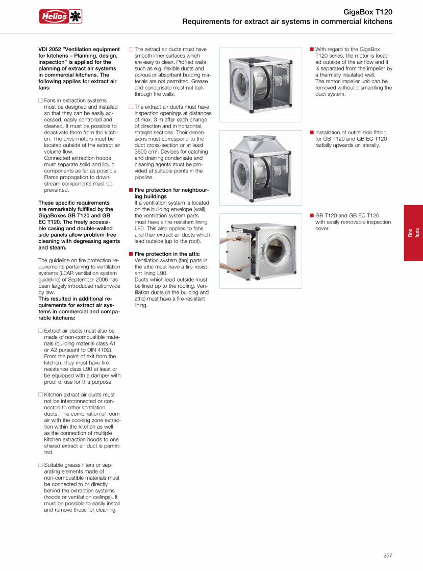
n With regard to the GigaBox T120 series, the motor is locat-ed outside of the air flow and it is separated from the impeller by a thermally insulated wall.
The motor-impeller unit can be removed without dismantling the duct system.
n Installation of outlet-side fitting for GB T120 and GB EC T120 radially upwards or laterally.
n GB T120 and GB EC T120 with easily removable inspection
cover.
257
GigaBox EC centrifugal fansSelection table
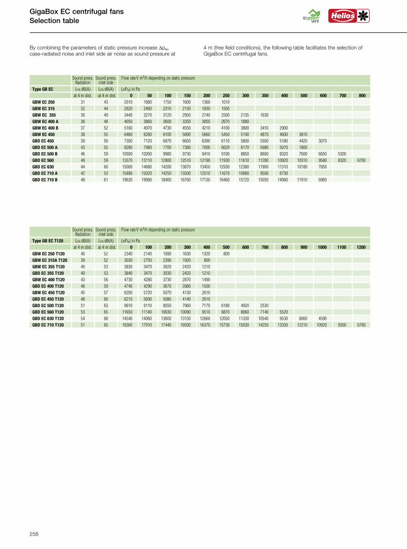
By combining the parameters of static pressure increase Dpfa, case-radiated noise and inlet side air noise as sound pressure at
4 m (free field conditions), the following table facilitates the selection of GigaBox EC centrifugal fans.
800 700 600 500 400 350 300 250 200 150 100 50 0 at 4 m dist. at 4 m dist.
GBD EC 560 49 59 13370 13110 12800 12510 12190 11930 11610 11280 10920 10310 9580 8320 6700 GBD EC 630 44 60 15000 14680 14200 13870 13450 12930 12380 11900 11310 10180 7850 GBD EC 710 A 42 53 15890 15020 14250 13500 12510 11670 10680 9500 6730 GBD EC 710 B 48 61 19630 19060 18400 16760 17130 16460 15720 15050 14060 11910 6960
GBD EC 500 B 46 59 10500 10260 9980 9730 9410 9100 8850 8600 8320 7600 6650 5300 GBD EC 500 A 43 55 8280 7980 7700 7380 7000 6620 6170 5680 5070 1800 GBD EC 450 39 56 7300 7120 6870 6650 6390 6110 5800 5500 5180 4420 3070
GBW EC 400 B 37 52 5160 4970 4730 4550 4210 4100 3800 3410 2900 GBW EC 400 A 36 48 4050 3860 3600 3350 3050 2670 1880
GBW EC 315 32 44 2620 2460 2310 2130 1830 1500 GBW EC 355 30 49 3440 3270 3120 2950 2740 2500 2135 1630
GBW EC 250 31 43 2010 1880 1750 1600 1360 1010
GBW EC 450 38 55 6460 6280 6100 5890 5660 5450 5190 4870 4600 3810
Type GB EC LPA dB(A) LPA dB(A) (DPfa) in Pa
Sound press. Sound press. Flow rate .V m3/h depending on static pressure
Radiation inlet side
1200 1100 1000 900 800 700 600 500 400 300 200 100 0 at 4 m dist. at 4 m dist.
GBD EC 560 T120 53 65 11650 11140 10630 10090 9510 8870 8060 7140 5520 GBD EC 630 T120 54 68 14540 14060 13600 13150 12660 12050 11330 10540 9530 8060 4590 GBD EC 710 T120 51 65 18360 17910 17440 16930 16370 15730 15030 14250 13330 12210 10920 9300 6760
GBD EC 500 T120 51 63 9610 9110 8550 7960 7170 6180 4920 2530 GBD EC 450 T120 48 60 6210 5690 5080 4140 2610 GBW EC 450 T120 45 57 6200 5720 5070 4130 2610
GBW EC 400 T120 43 56 4730 4280 3730 2870 1490 GBD EC 355 T120 40 53 3840 3470 3030 2420 1210
GBW EC 315A T120 39 52 3030 2750 2390 1920 800 GBW EC 355 T120 40 53 3830 3470 3020 2420 1210
GBW EC 250 T120 40 52 2340 2140 1890 1630 1320 800
GBD EC 400 T120 46 59 4740 4290 3670 2880 1500
Type GB EC T120 LPA dB(A) LPA dB(A) (DPfa) in Pa
Sound press. Sound press. Flow rate .V m3/h depending on static pressure
Radiation inlet side
258
Box
fans
GigaBox AC centrifugal fansSelection table
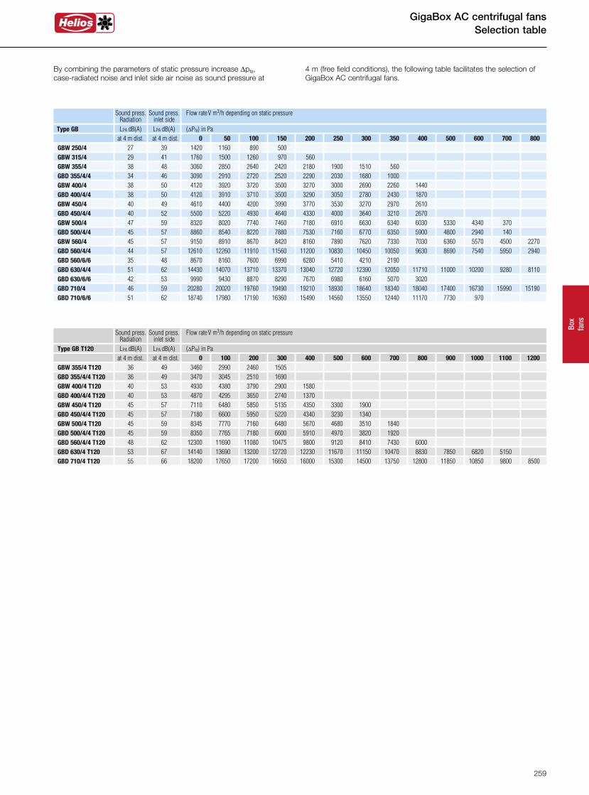
GBD 710/6/6 51 62 18740 17980 17190 16360 15490 14560 13550 12440 11170 7730 970
恴箎Type GB LPA dB(A) LPA dB(A) (DPfa) in Pa
GBD 710/4 46 59 20280 20020 19760 19490 19210 18930 18640 18340 18040 17400 16730 15990 15190 GBD 630/6/6 42 53 9990 9430 8870 8290 7670 6980 6160 5070 3020
GBD 630/4/4 51 62 14430 14070 13710 13370 13040 12720 12390 12050 11710 11000 10200 9280 8110 GBD 560/6/6 35 48 8670 8160 7600 6990 6280 5410 4210 2190 GBD 560/4/4 44 57 12610 12260 11910 11560 11200 10830 10450 10050 9630 8690 7540 5950 2940
GBW 560/4 45 57 9150 8910 8670 8420 8160 7890 7620 7330 7030 6360 5570 4500 2270 GBD 500/4/4 45 57 8860 8540 8220 7880 7530 7160 6770 6350 5900 4800 2940 140 GBW 500/4 47 59 8320 8020 7740 7460 7180 6910 6630 6340 6030 5330 4340 370
GBW 450/4 40 49 4610 4400 4200 3990 3770 3530 3270 2970 2610 GBD 400/4/4 38 50 4120 3910 3710 3500 3290 3050 2780 2430 1870
GBD 355/4/4 34 46 3090 2910 2720 2520 2290 2030 1680 1000 GBW 400/4 38 50 4120 3920 3720 3500 3270 3000 2690 2260 1440
GBW 355/4 38 48 3060 2850 2640 2420 2180 1900 1510 560 GBW 315/4 29 41 1760 1500 1260 970 560 GBW 250/4 27 39 1420 1160 890 500 at 4 m dist. at 4 m dist. 800 700 600 500 400 350 300 250 200 150 100 50 0
Sound press. Sound press. Flow rate .V m3/h depending on static pressure
Radiation inlet side
GBD 450/4/4 40 52 5500 5220 4930 4640 4330 4000 3640 3210 2670
1200 1100 1000 900 800 700 600 500 400 300 200 100 0 at 4 m dist. at 4 m dist. Type GB T120 LPA dB(A) LPA dB(A) (DPfa) in Pa
Sound press. Sound press. Flow rate .V m3/h depending on static pressure
Radiation inlet side
GBD 710/4 T120 55 66 18200 17650 17200 16650 16000 15300 14500 13750 12800 11850 10850 9800 8500 GBD 630/4 T120 53 67 14140 13690 13200 12720 12230 11670 11150 10470 8830 7850 6820 5150 GBD 560/4/4 T120 48 62 12300 11690 11080 10475 9800 9120 8410 7430 6000 GBD 500/4/4 T120 45 59 8350 7765 7180 6600 5910 4970 3820 1920 GBW 500/4 T120 45 59 8345 7770 7160 6480 5670 4680 3510 1840
GBW 450/4 T120 45 57 7110 6480 5850 5135 4350 3300 1900 GBD 400/4/4 T120 40 53 4870 4295 3650 2740 1370
GBD 355/4/4 T120 36 49 3470 3045 2510 1690 GBW 400/4 T120 40 53 4930 4380 3790 2900 1580
GBW 355/4 T120 36 49 3460 2990 2460 1505
GBD 450/4/4 T120 45 57 7180 6600 5950 5220 4340 3230 1340
By combining the parameters of static pressure increase Dpfa, case-radiated noise and inlet side air noise as sound pressure at
4 m (free field conditions), the following table facilitates the selection of GigaBox AC centrifugal fans.
259
1) Multiple EC fans can normally be connected. 2) Alternative electronic diff. pressure / temperature controller (EDR/ETR, No. 01437/01438) or three level speed switch (SU/SA, No. 04266/04267).
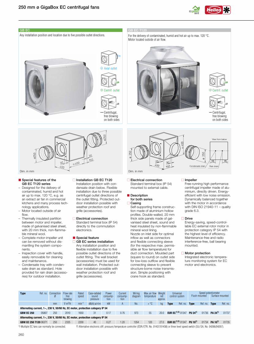
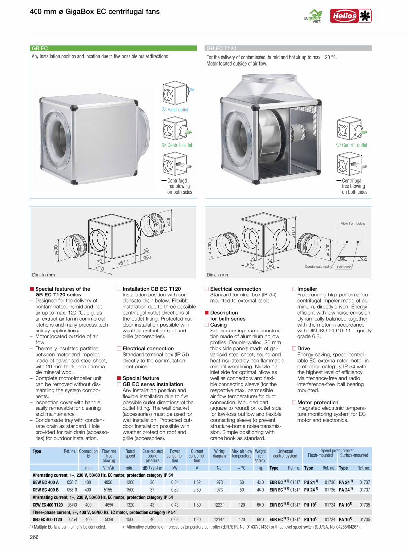
n Installation GB EC T120 Installation position with con-
densate drain below. Flexible installation due to three possible centrifugal outlet directions of the outlet fitting. Protected out-door installation possible with weather protection roof and grille (accessories).
n Electrical connection Standard terminal box (IP 54) directly to the commutation electronics.
n Special featuren GB EC series installation Any installation position and
flexible installation due to five possible outlet directions of the outlet fitting. The wall bracket (accessories) must be used for wall installation. Protected out-door installation possible with weather protection roof and grille (accessories).
n Special features of the GB EC T120 series– Designed for the delivery of
contaminated, humid and hot air up to max. 120 °C, e.g. as an extract air fan in commercial kitchens and many process tech-nology applications.
– Motor located outside of air flow.
– Thermally insulated partition between motor and impeller, made of galvanised steel sheet, with 20 mm thick, non-flamma-ble mineral wool.
– Complete motor-impeller unit can be removed without dis-mantling the system compo-nents.
– Inspection cover with handle, easily removable for cleaning and maintenance.
– Condensate tray with conden-sate drain as standard. Hole provided for rain drain (accesso-ries) for outdoor installation.
n Electrical connection Standard terminal box (IP 54) mounted to external cable.
n Description for both seriesn Casing Self-supporting frame construc-
tion made of aluminium hollow profiles. Double-walled, 20 mm thick side panels made of gal-vanised steel sheet, sound and heat insulated by non-flammable mineral wool lining. Nozzle on inlet side for optimal inflow as well as connectors and flexible connecting sleeve (for the respective max. permis-sible air flow temperature) for duct connection. Moulded part (square to round) on outlet side for low-loss outflow and flexible connecting sleeve to prevent structure-borne noise transmis-sion. Simple positioning with crane hook as standard.
n Impeller Free-running high performance
centrifugal impeller made of alu-minium, directly driven. Energy-
efficient with low noise emission. Dynamically balanced together with the motor in accordance with DIN ISO 21940-11 – quality grade 6.3.
n Drive Energy-saving, speed-control-
lable EC external rotor motor in protection category IP 54 with the highest level of efficiency. Maintenance-free and radio interference-free, ball bearing mounted.
n Motor protection Integrated electronic tempera-ture monitoring system for EC motor and electronics.
Centrif. outlet
Centrifugal, free blowing on both sides
R
GB EC T120
For the delivery of contaminated, humid and hot air up to max. 120 °C. Motor located outside of air flow.
Axial outletA
Centrif. outlet
Centrifugal, free blowing on both sides
GB EC
R
Any installation position and location due to five possible outlet directions.
Dim. in mm Dim. in mm
250 mm ø GigaBox EC centrifugal fans
Connection Ø
Flow ratefree
blowing
GBW EC 250 05807 250 2010 1650 31 973 20.00.17 0.76 55 EUR EC1) 2) 01347 PU 241) 01736
Type Ref. no. Ratedspeed
Case-radiated sound
pressure
Wiringdiagram
Weight net
approx.
mm.V m3/h min-1 dB(A) at 4 m No. kg
Powerconsump-
tion
kW
Current consump-
tion
A
Max. air flowtemperature
+ °C
Universal control system
Type Ref. no. Type Ref. no.
PA 241) 01737
Type Ref. no.
Speed potentiometer Flush-mounted Surface-mounted
GBW EC 250 T120 06371 250 2335 2200 40 1354 27.00.27 1.20 120 EUR EC1) 2) 01347 PU 101) 01734 PA 101) 01735
Alternating current, 1~, 230 V, 50/60 Hz, EC motor, protection category IP 54
Alternating current, 1~, 230 V, 50/60 Hz, EC motor, protection category IP 54
View from below
Condensate drain Rain drain
260

GigaBox EC centrifugal fans 250 mm ø
n Accessories for both series
Vibration dampers for indoor in-stallation. 1 set = 4 pcs.SDD-U Ref. no. 05627 Wall bracket for wall installation.GB-WK 250 Ref. no. 05625
Weather protection grille for out-let-side coverage.GB-WSG 250 Ref. no. 05637
Weather protection roof for pro-tected outdoor installation.GB-WSD 250 Ref. no. 05746
n Special accessories
n for GB EC seriesCondensate tray with drain con-nectors (central) for duct/hose connection.GB-KW 250 Ref. no. 05642(a condensate tray with conden-sate drain is included in delivery for GB EC T120).
n for GB EC T120 seriesRain drain for outdoor installation (Hole in casing base already pro-vided).GB-RA Ref. no. 09418
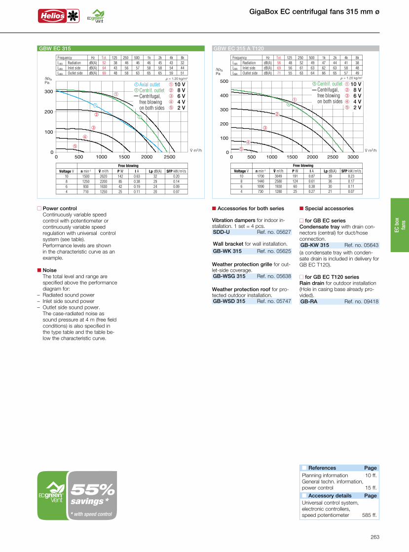
n Power control Continuously variable speed control with potentiometer or continuously variable speed regulation with universal control system (see table).
Performance levels are shown in the characteristic curve as an example.
n Noise The total level and range are specified above the performance diagram for:
– Radiated sound power– Inlet side sound power– Outlet side sound power.
The case-radiated noise as sound pressure at 4 m (free field conditions) is also specified in the type table and the table be-low the characteristic curve.
n References Page Planning information 10 ff.General techn. information,power control 15 ff.
n Accessory details Page Universal control system,electronic controllers,speed potentiometer 585 ff.
Frequency Hz Tot. 125 250 500 1k 2k 4k 8k LWA Radiation dB(A) 51 41 48 44 41 39 36 29 LWA Inlet side dB(A) 63 44 54 56 58 57 52 45 LWA Outlet side dB(A) 67 45 57 59 62 62 56 50
á
û
ô
ê
â
V· m3/h
DpfaPa
r = 1.20 kg/m3
GBW EC 250
â 10 Vê 8 Vô 6 V û 4 V á 2 V
R
A
Free blowing Voltage V n min-1 V· m3/h P W I A Lp dB(A) SFP kW/m3/s 10 1650 2010 120 0.53 31 0.22 8 1325 1600 70 0.31 28 0.15 6 1000 1200 35 0.16 22 0.11 4 710 830 21 0.09 17 0.09
Axial outlet Centrif. outlet Centrifugal, free blowing on both sides
RA
Frequency Hz Tot. 125 250 500 1k 2k 4k 8k LWA Radiation dB(A) 57 47 55 50 43 40 32 29 LWA Inlet side dB(A) 69 51 59 62 64 65 59 49 LWA Outlet side dB(A) 72 52 63 66 67 64 63 54
R
V· m3/h
DpfaPa
r = 1.20 kg/m3
á
û
ôê
â
GBW EC 250 T120
Free blowing Voltage V n min-1 V· m3/h P W I A Lp dB(A) SFP kW/m3/s 10 2310 2335 169 0.76 40 0.26 8 2300 2330 167 0.75 40 0.26 6 2144 2180 140 0.63 38 0.23 4 1697 1730 73 0.35 33 0.15
Centrif. outlet Centrifugal,
free blowing on both sides
R â 10 Vê 8 Vô 6 V û 4 V á 2 V
savings ** with speed control
261
EC b
ox
fans

315 mm ø GigaBox EC centrifugal fans
1) Multiple EC fans can normally be connected. 2) Alternative electronic diff. pressure / temperature controller (EDR/ETR, No. 01437/01438) or three level speed switch (SU/SA, No. 04266/04267).
Centrif. outlet
Centrifugal, free blowing on both sides
R
GB EC T120
For the delivery of contaminated, humid and hot air up to max. 120 °C. Motor located outside of air flow.
Axial outletA
Centrif. outlet
Centrifugal, free blowing on both sides
GB EC
R
Any installation position and location due to five possible outlet directions.
Dim. in mm Dim. in mm
Connection Ø
Flow ratefree
blowing
GBW EC 315 05808 315 2617 1500 32 973 31.00.20 0.9 55 EUR EC1) 2) 01347 PU 241) 01736
Type Ref. no. Ratedspeed
Case-radiated sound
pressure
Wiringdiagram
Weight net
approx.
mm.V m3/h min-1 dB(A) at 4 m No. kg
Powerconsump-
tion
kW
Current consump-
tion
A
Max. air flowtemperature
+ °C
Universal control system
Speed potentiometer Flush-mounted Surface-mounted
Type Ref. no. Type Ref. no.
PA 241) 01737
Type Ref. no.
GBW EC 315 A T120 06370 315 3049 1700 39 1223.1 42.00.29 1.3 120 EUR EC1) 2) 01347 PU 101) 01734 PA 101) 01735
Alternating current, 1~, 230 V, 50/60 Hz, EC motor, protection category IP 54
Alternating current, 1~, 230 V, 50/60 Hz, EC motor, protection category IP 54
n Installation GB EC T120 Installation position with con-
densate drain below. Flexible installation due to three possible centrifugal outlet directions of the outlet fitting. Protected out-door installation possible with weather protection roof and grille (accessories).
n Electrical connection Standard terminal box (IP 54) directly to the commutation electronics.
n Special featuren GB EC series installation Any installation position and
flexible installation due to five possible outlet directions of the outlet fitting. The wall bracket (accessories) must be used for wall installation. Protected out-door installation possible with weather protection roof and grille (accessories).
n Special features of the GB EC T120 series– Designed for the delivery of
contaminated, humid and hot air up to max. 120 °C, e.g. as an extract air fan in commercial kitchens and many process tech-nology applications.
– Motor located outside of air flow.
– Thermally insulated partition between motor and impeller, made of galvanised steel sheet, with 20 mm thick, non-flamma- ble mineral wool.– Complete motor-impeller unit
can be removed without dis-mantling the system compo-nents.
– Inspection cover with handle, easily removable for cleaning and maintenance.
– Condensate tray with conden-sate drain as standard. Hole provided for rain drain (accesso-ries) for outdoor installation.
n Electrical connection Standard terminal box (IP 54) mounted to external cable.
n Description for both seriesn Casing Self-supporting frame construc-
tion made of aluminium hollow profiles. Double-walled, 20 mm thick side panels made of gal-vanised steel sheet, sound and heat insulated by non-flammable mineral wool lining. Nozzle on inlet side for optimal inflow as well as connectors and flexi-ble connecting sleeve (for the respective max. permissible air flow temperature) for duct connection. Moulded part (square to round) on outlet side for low-loss outflow and flexible connecting sleeve to prevent structure-borne noise transmis-sion. Simple positioning with crane hook as standard.
n Impeller Free-running high performance
centrifugal impeller made of alu-minium, directly driven. Energy-
efficient with low noise emission. Dynamically balanced together with the motor in accordance with DIN ISO 21940-11 – quality grade 6.3.
n Drive Energy-saving, speed-control-
lable EC external rotor motor in protection category IP 54 with the highest level of efficiency. Maintenance-free and radio interference-free, ball bearing mounted.
n Motor protection Integrated electronic tempera-ture monitoring system for EC motor and electronics.
View from below
Condensate drain Rain drain
262
Frequency Hz Tot. 125 250 500 1k 2k 4k 8k LWA Radiation dB(A) 52 38 46 46 46 45 43 32 LWA Inlet side dB(A) 64 43 56 57 58 58 54 44 LWA Outlet side dB(A) 69 48 58 63 65 65 59 51
á
û
ô
ê
â
V· m3/h
DpfaPa
r = 1.20 kg/m3
GBW EC 315
â 10 Vê 8 Vô 6 V û 4 V á 2 V
Axial outlet Centrif. outlet Centrifugal,
free blowing on both sides
Free blowing Voltage V n min-1 V· m3/h P W I A Lp dB(A) SFP kW/m3/s 10 1500 2620 142 0.63 32 0.20 8 1250 2200 85 0.38 29 0.14 6 930 1630 42 0.19 24 0.09 4 710 1250 25 0.11 20 0.07
R
A
R
A
GigaBox EC centrifugal fans 315 mm ø
n Accessories for both series
Vibration dampers for indoor in-stallation. 1 set = 4 pcs.SDD-U Ref. no. 05627 Wall bracket for wall installation.GB-WK 315 Ref. no. 05625
Weather protection grille for out-let-side coverage.GB-WSG 315 Ref. no. 05638
Weather protection roof for pro-tected outdoor installation.GB-WSD 315 Ref. no. 05747
n Special accessories
n for GB EC seriesCondensate tray with drain con-nectors (central) for duct/hose connection.GB-KW 315 Ref. no. 05643(a condensate tray with conden-sate drain is included in delivery for GB EC T120).
n for GB EC T120 seriesRain drain for outdoor installation(Hole in casing base already pro-vided).GB-RA Ref. no. 09418
Frequency Hz Tot. 125 250 500 1k 2k 4k 8k LWA Radiation dB(A) 56 48 52 49 47 44 41 38 LWA Inlet side dB(A) 69 56 61 63 62 63 58 48 LWA Outlet side dB(A) 71 55 63 64 66 65 57 49
R
V· m3/h
DpfaPa
r = 1.20 kg/m3
á
û
ô
ê
â
GBW EC 315 A T120
Free blowing Voltage V n min-1 V· m3/h P W I A Lp dB(A) SFP kW/m3/s 10 1700 3049 191 0.87 39 0.23 8 1440 2580 124 0.61 36 0.17 6 1090 1930 60 0.38 30 0.11 4 730 1280 25 0.27 21 0.07
Centrif. outlet Centrifugal,
free blowing on both sides
R â 10 Vê 8 Vô 6 V û 4 V á 2 V
n References Page Planning information 10 ff.General techn. information,power control 15 ff.
n Accessory details Page Universal control system,electronic controllers,speed potentiometer 585 ff.
n Power control Continuously variable speed control with potentiometer or continuously variable speed regulation with universal control system (see table).
Performance levels are shown in the characteristic curve as an example.
n Noise The total level and range are specified above the performance diagram for:
– Radiated sound power– Inlet side sound power– Outlet side sound power.
The case-radiated noise as sound pressure at 4 m (free field conditions) is also specified in the type table and the table be-low the characteristic curve.
savings ** with speed control
263
EC b
ox
fans
355 mm ø GigaBox EC centrifugal fans
1) Multiple EC fans can normally be connected. 2) Alternative electronic diff. pressure / temperature controller (EDR/ETR, No. 01437/01438) or three level speed switch (SU/SA, No. 04266/04267).
Centrif. outlet
Centrifugal, free blowing on both sides
R
GB EC T120
For the delivery of contaminated, humid and hot air up to max. 120 °C. Motor located outside of air flow.
Axial outletA
Centrif. outlet
Centrifugal, free blowing on both sides
GB EC
R
Any installation position and location due to five possible outlet directions.
Dim. in mm Dim. in mm
Connection Ø
Flow ratefree
blowing
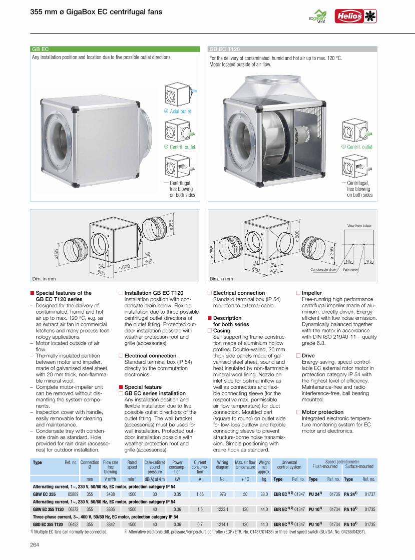
GBW EC 355 05809 355 3438 1500 30 973 33.00.35 1.55 50 EUR EC1) 2) 01347 PU 241) 01736
Type Ref. no. Ratedspeed
Case-radiated sound
pressure
Wiringdiagram
Weight net
approx.
mm.V m3/h min-1 dB(A) at 4 m No. kg
Powerconsump-
tion
kW
Current consump-
tion
A
Max. air flowtemperature
+ °C
Universal control system
Speed potentiometer Flush-mounted Surface-mounted
Type Ref. no. Type Ref. no.
PA 241) 01737
Type Ref. no.
GBW EC 355 T120 06372 355 3836 1500 40 1223.1 44.00.36 1.5 120 EUR EC1) 2) 01347 PU 101) 01734 PA 101) 01735
GBD EC 355 T120 06452 355 3842 1500 40 1214.1 44.00.36 0.7 120 EUR EC1) 2) 01347 PU 101) 01734 PA 101) 01735
Alternating current, 1~, 230 V, 50/60 Hz, EC motor, protection category IP 54
Alternating current, 1~, 230 V, 50/60 Hz, EC motor, protection category IP 54
Three-phase current, 3~, 400 V, 50/60 Hz, EC motor, protection category IP 54
n Installation GB EC T120 Installation position with con-
densate drain below. Flexible installation due to three possible centrifugal outlet directions of the outlet fitting. Protected out-door installation possible with weather protection roof and grille (accessories).
n Electrical connection Standard terminal box (IP 54) directly to the commutation electronics.
n Special featuren GB EC series installation Any installation position and
flexible installation due to five possible outlet directions of the outlet fitting. The wall bracket (accessories) must be used for wall installation. Protected out-door installation possible with weather protection roof and grille (accessories).
n Special features of the GB EC T120 series– Designed for the delivery of
contaminated, humid and hot air up to max. 120 °C, e.g. as an extract air fan in commercial kitchens and many process tech-nology applications.
– Motor located outside of air flow.
– Thermally insulated partition between motor and impeller, made of galvanised steel sheet, with 20 mm thick, non-flamma- ble mineral wool.– Complete motor-impeller unit
can be removed without dis-mantling the system compo-nents.
– Inspection cover with handle, easily removable for cleaning and maintenance.
– Condensate tray with conden-sate drain as standard. Hole provided for rain drain (accesso-ries) for outdoor installation.
n Electrical connection Standard terminal box (IP 54) mounted to external cable.
n Description for both seriesn Casing Self-supporting frame construc-
tion made of aluminium hollow profiles. Double-walled, 20 mm thick side panels made of gal-vanised steel sheet, sound and heat insulated by non-flammable mineral wool lining. Nozzle on inlet side for optimal inflow as well as connectors and flexi-ble connecting sleeve (for the respective max. permissible air flow temperature) for duct connection. Moulded part (square to round) on outlet side for low-loss outflow and flexible connecting sleeve to prevent structure-borne noise transmis-sion. Simple positioning with crane hook as standard.
n Impeller Free-running high performance
centrifugal impeller made of alu-minium, directly driven. Energy-
efficient with low noise emission. Dynamically balanced together with the motor in accordance with DIN ISO 21940-11 – quality grade 6.3.
n Drive Energy-saving, speed-control-
lable EC external rotor motor in protection category IP 54 with the highest level of efficiency. Maintenance-free and radio interference-free, ball bearing mounted.
n Motor protection Integrated electronic tempera-ture monitoring system for EC motor and electronics.
View from below
Condensate drain Rain drain
264
GigaBox EC centrifugal fans 355 mm ø
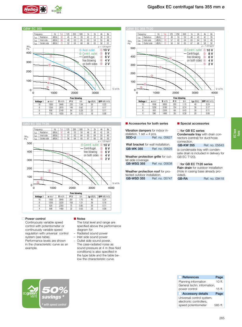
Frequency Hz Tot. 125 250 500 1k 2k 4k 8k LWA Radiation dB(A) 50 45 44 39 42 41 38 29 LWA Inlet side dB(A) 69 49 63 65 62 59 55 48 LWA Outlet side dB(A) 72 52 64 68 66 63 58 51
á
û
ô
ê
â
V· m3/h
DpfaPa
r = 1.20 kg/m3
GBW EC 355
â 10 Vê 8 Vô 6 V û 4 V á 2 V
Axial outlet Centrif. outlet Centrifugal,
free blowing on both sides
Free blowing Voltage V n min-1 V· m3/h P W I A Lp dB(A) SFP kW/m3/s 10 1500 3440 235 1.04 30 0.25 8 1250 2870 140 0.62 27 0.17 6 930 2140 64 0.28 22 0.11 4 710 1630 34 0.15 18 0.08
R
A
R
A
n Accessories for both series
Vibration dampers for indoor in-stallation. 1 set = 4 pcs.SDD-U Ref. no. 05627 Wall bracket for wall installation.GB-WK 355 Ref. no. 05625
Weather protection grille for out-let-side coverage.GB-WSG 355 Ref. no. 05638
Weather protection roof for pro-tected outdoor installation.GB-WSD 355 Ref. no. 05747
n Special accessories
n for GB EC seriesCondensate tray with drain con-nectors (central) for duct/hoseconnection.GB-KW 355 Ref. no. 05643(a condensate tray with conden-sate drain is included in delivery for GB EC T120).
n for GB EC T120 seriesRain drain for outdoor installation(Hole in casing base already pro-vided).GB-RA Ref. no. 09418
Frequency Hz Tot. 125 250 500 1k 2k 4k 8k LWA Radiation dB(A) 57 49 53 50 48 45 42 39 LWA Inlet side dB(A) 70 57 62 64 63 64 59 49 LWA Outlet side dB(A) 72 56 64 65 67 66 58 50
V· m3/h
DpfaPa
r = 1.20 kg/m3
á
û
ô
ê
â
GBD EC 355 T120
Free blowing Voltage V n min-1 V· m3/h P W I A Lp dB(A) SFP kW/m3/s 10 1500 3840 261 1.70 40 0.24 8 1250 3220 160 1.31 36 0.18 6 920 2350 75 0.85 30 0.11 4 590 1480 32 0.63 20 0.08
R
Centrif. outlet Centrifugal,
free blowing on both sides
R â 10 Vê 8 Vô 6 V û 4 V á 2 V
Frequency Hz Tot. 125 250 500 1k 2k 4k 8k LWA Radiation dB(A) 57 49 53 50 48 45 42 39 LWA Inlet side dB(A) 70 57 62 64 63 64 59 49 LWA Outlet side dB(A) 72 56 64 65 67 66 58 50
R
V· m3/h
DpfaPa
r = 1.20 kg/m3
áû
ô
ê
â
GBW EC 355 T120
Free blowing Voltage V n min-1 V· m3/h P W I A Lp dB(A) SFP kW/m3/s 10 1500 3830 255 1.15 40 0.24 8 1250 3190 154 0.74 36 0.17 6 920 2330 68 0.43 30 0.11 4 590 1490 26 0.28 20 0.06
Centrif. outlet Centrifugal,
free blowing on both sides
R â 10 Vê 8 Vô 6 V û 4 V á 2 V
n References Page Planning information 10 ff.General techn. information,power control 15 ff.
n Accessory details Page Universal control system,electronic controllers,speed potentiometer 585 ff.
n Power control Continuously variable speed control with potentiometer or continuously variable speed regulation with universal control system (see table).
Performance levels are shown in the characteristic curve as an example.
n Noise The total level and range are specified above the performance diagram for:
– Radiated sound power– Inlet side sound power– Outlet side sound power.
The case-radiated noise as sound pressure at 4 m (free field conditions) is also specified in the type table and the table be-low the characteristic curve.
savings ** with speed control
265
EC b
ox
fans
400 mm ø GigaBox EC centrifugal fans
Centrif. outlet
Centrifugal, free blowing on both sides
R
GB EC T120
For the delivery of contaminated, humid and hot air up to max. 120 °C. Motor located outside of air flow.
Axial outletA
Centrif. outlet
Centrifugal, free blowing on both sides
GB EC
R
Any installation position and location due to five possible outlet directions.
Dim. in mm Dim. in mm
1) Multiple EC fans can normally be connected. 2) Alternative electronic diff. pressure / temperature controller (EDR/ETR, No. 01437/01438) or three level speed switch (SU/SA, No. 04266/04267).
Connection Ø
Flow ratefree
blowing
Type Ref. no. Ratedspeed
Case-radiated sound
pressure
Wiringdiagram
Weight net
approx.
mm.V m3/h min-1 dB(A) at 4 m No. kg
Powerconsump-
tion
kW
Current consump-
tion
A
Max. air flowtemperature
+ °C
Universal control system
Speed potentiometer Flush-mounted Surface-mounted
Type Ref. no. Type Ref. no. Type Ref. no.
GBW EC 400 T120 06453 400 4650 1320 43 1223.1 60.00.43 1.80 120 EUR EC1) 2) 01347 PU 101) 01734 PA 101) 01735
GBD EC 400 T120 06454 400 5090 1500 46 1214.1 60.00.62 1.20 120 EUR EC1) 2) 01347 PU 101) 01734 PA 101) 01735
GBW EC 400 A 05817 400 4050 1200 36 973 43.00.34 1.52 50 EUR EC1) 2) 01347 PU 24 1) 01736 PA 24 1) 01737
GBW EC 400 B 05810 400 5155 1500 37 973 46.00.62 2.80 50 EUR EC1) 2) 01347 PU 24 1) 01736 PA 24 1) 01737
Alternating current, 1~, 230 V, 50/60 Hz, EC motor, protection category IP 54
Three-phase current, 3~, 400 V, 50/60 Hz, EC motor, protection category IP 54
Alternating current, 1~, 230 V, 50/60 Hz, EC motor, protection category IP 54
n Installation GB EC T120 Installation position with con-
densate drain below. Flexible installation due to three possible centrifugal outlet directions of the outlet fitting. Protected out-door installation possible with weather protection roof and grille (accessories).
n Electrical connection Standard terminal box (IP 54) directly to the commutation electronics.
n Special featuren GB EC series installation Any installation position and
flexible installation due to five possible outlet directions of the outlet fitting. The wall bracket (accessories) must be used for wall installation. Protected out-door installation possible with weather protection roof and grille (accessories).
n Special features of the GB EC T120 series– Designed for the delivery of
contaminated, humid and hot air up to max. 120 °C, e.g. as an extract air fan in commercial kitchens and many process tech-nology applications.
– Motor located outside of air flow.
– Thermally insulated partition between motor and impeller, made of galvanised steel sheet, with 20 mm thick, non-flamma- ble mineral wool.– Complete motor-impeller unit
can be removed without dis-mantling the system compo-nents.
– Inspection cover with handle, easily removable for cleaning and maintenance.
– Condensate tray with conden-sate drain as standard. Hole provided for rain drain (accesso-ries) for outdoor installation.
n Electrical connection Standard terminal box (IP 54) mounted to external cable.
n Description for both seriesn Casing Self-supporting frame construc-
tion made of aluminium hollow profiles. Double-walled, 20 mm thick side panels made of gal-vanised steel sheet, sound and heat insulated by non-flammable mineral wool lining. Nozzle on inlet side for optimal inflow as well as connectors and flexi-ble connecting sleeve (for the respective max. permissible air flow temperature) for duct connection. Moulded part (square to round) on outlet side for low-loss outflow and flexible connecting sleeve to prevent structure-borne noise transmis-sion. Simple positioning with crane hook as standard.
n Impeller Free-running high performance
centrifugal impeller made of alu-minium, directly driven. Energy-
efficient with low noise emission. Dynamically balanced together with the motor in accordance with DIN ISO 21940-11 – quality grade 6.3.
n Drive Energy-saving, speed-control-
lable EC external rotor motor in protection category IP 54 with the highest level of efficiency. Maintenance-free and radio interference-free, ball bearing mounted.
n Motor protection Integrated electronic tempera-ture monitoring system for EC motor and electronics.
View from below
Condensate drain Rain drain
266
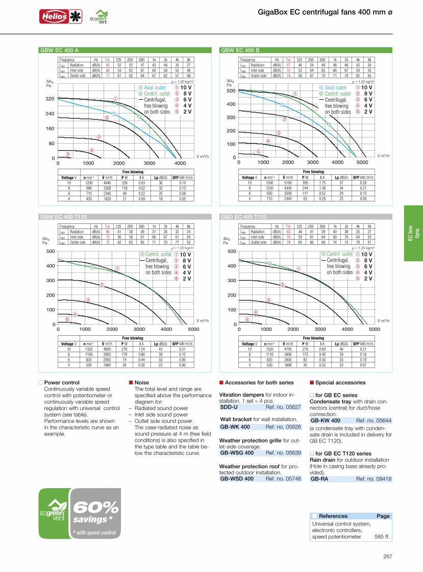
Frequency Hz Tot. 125 250 500 1k 2k 4k 8k LWA Radiation dB(A) 57 46 54 49 48 46 43 39 LWA Inlet side dB(A) 72 53 64 65 66 67 59 53 LWA Outlet side dB(A) 76 56 67 70 71 70 62 55
á
û
ô
ê
â
V· m3/h
DpfaPa
r = 1.20 kg/m3
GBW EC 400 B
â 10 Vê 8 Vô 6 V û 4 V á 2 V
Axial outlet Centrif. outlet Centrifugal,
free blowing on both sides
Free blowing Voltage V n min-1 V· m3/h P W I A Lp dB(A) SFP kW/m3/s 10 1500 5160 395 1.75 37 0.28 8 1250 4300 244 1.08 34 0.21 6 930 3200 117 0.52 29 0.13 4 710 2440 63 0.28 25 0.09
R
A
R
A
GigaBox EC centrifugal fans 400 mm ø
n Accessories for both series
Vibration dampers for indoor in-stallation. 1 set = 4 pcs.SDD-U Ref. no. 05627 Wall bracket for wall installation.GB-WK 400 Ref. no. 05626
Weather protection grille for out-let-side coverage.GB-WSG 400 Ref. no. 05639
Weather protection roof for pro-tected outdoor installation.GB-WSD 400 Ref. no. 05748
n Special accessories
n for GB EC seriesCondensate tray with drain con-nectors (central) for duct/hoseconnection.GB-KW 400 Ref. no. 05644(a condensate tray with conden-sate drain is included in delivery for GB EC T120).
n for GB EC T120 seriesRain drain for outdoor installation(Hole in casing base already pro-vided).GB-RA Ref. no. 09418
Frequency Hz Tot. 125 250 500 1k 2k 4k 8k LWA Radiation dB(A) 60 41 38 36 37 35 32 24 LWA Inlet side dB(A) 73 56 58 61 66 67 61 50 LWA Outlet side dB(A) 75 62 63 65 71 70 77 53
R
V· m3/h
DpfaPa
r = 1.20 kg/m3
áû
ô
ê
â
GBW EC 400 T120
Free blowing Voltage V n min-1 V· m3/h P W I A Lp dB(A) SFP kW/m3/s 10 1320 4650 276 1.24 43 0.21 8 1100 3950 170 0.80 39 0.15 6 820 2950 74 0.44 33 0.09 4 530 1880 29 0.30 23 0.06
Centrif. outlet Centrifugal,
free blowing on both sides
R â 10 Vê 8 Vô 6 V û 4 V á 2 V
Frequency Hz Tot. 125 250 500 1k 2k 4k 8k LWA Radiation dB(A) 63 44 41 39 40 38 35 27 LWA Inlet side dB(A) 76 59 61 64 69 70 64 53 LWA Outlet side dB(A) 78 65 66 68 74 73 70 57
R
V· m3/h
DpfaPa
r = 1.20 kg/m3
á
û
ô
ê
â
GBD EC 400 T120
Free blowing Voltage V n min-1 V· m3/h P W I A Lp dB(A) SFP kW/m3/s 10 1320 4750 279 0.60 46 0.21 8 1110 3990 173 0.45 39 0.16 6 820 2900 82 0.30 33 0.10 4 530 1890 35 0.22 23 0.07
Centrif. outlet Centrifugal,
free blowing on both sides
R â 10 Vê 8 Vô 6 V û 4 V á 2 V
n References Page Universal control system,electronic controllers,speed potentiometer 585 ff.
n Power control Continuously variable speed control with potentiometer or continuously variable speed regulation with universal control system (see table).
Performance levels are shown in the characteristic curve as an example.
n Noise The total level and range are specified above the performance diagram for:
– Radiated sound power– Inlet side sound power– Outlet side sound power.
The case-radiated noise as sound pressure at 4 m (free field conditions) is also specified in the type table and the table be-low the characteristic curve.
Frequency Hz Tot. 125 250 500 1k 2k 4k 8k LWA Radiation dB(A) 56 52 52 47 43 40 35 27 LWA Inlet side dB(A) 68 53 62 67 60 58 55 48 LWA Outlet side dB(A) 71 61 62 64 67 62 57 48
áû
ô
ê
â
V· m3/h
DpfaPa
r = 1.20 kg/m3
GBW EC 400 A
â 10 Vê 8 Vô 6 V û 4 V á 2 V
Axial outlet Centrif. outlet Centrifugal,
free blowing on both sides
Free blowing Voltage V n min-1 V· m3/h P W I A Lp dB(A) SFP kW/m3/s 10 1200 4040 209 0.93 36 0.19 8 990 3300 118 0.52 32 0.13 6 710 2340 49 0.22 25 0.08 4 430 1420 21 0.09 18 0.05
R
A
RA
savings ** with speed control
267
EC b
ox
fans
450 mm ø GigaBox EC centrifugal fans
1) Multiple EC fans can normally be connected. 2) Alternative electronic diff. pressure / temperature controller (EDR/ETR, No. 01437/01438) or three level speed switch (SU/SA, No. 04266/04267).
Centrif. outlet
Centrifugal, free blowing on both sides
R
GB EC T120
For the delivery of contaminated, humid and hot air up to max. 120 °C. Motor located outside of air flow.
Axial outletA
Centrif. outlet
Centrifugal, free blowing on both sides
GB EC
R
Any installation position and location due to five possible outlet directions.
Connection Ø
Flow ratefree
blowing
Type Ref. no. Ratedspeed
Case-radiated sound
pressure
Wiringdiagram
Weight net
approx.
mm.V m3/h min-1 dB(A) at 4 m No. kg
Powerconsump-
tion
kW
Current consump-
tion
A
Max. air flowtemperature
+ °C
Universal control system
Speed potentiometer Flush-mounted Surface-mounted
Type Ref. no. Type Ref. no. Type Ref. no.
GBW EC 450 T120 06475 450 6250 1230 45 1223.1 66.00.65 2.8 120 EUR EC1) 2) 01347 PU 101) 01734 PA 101) 01735
GBD EC 450 T120 06476 450 6450 1400 48 1214.1 66.00.95 1.7 120 EUR EC1) 2) 01347 PU 101) 01734 PA 101) 01735
GBW EC 450 05811 450 6458 1450 38 973 52.01.00 4.5 50 EUR EC1) 2) 01347 PU 24 1) 01736 PA 24 1) 01737
GBD EC 450 05812 450 7317 1500 39 976 52.01.00 1.8 55 EUR EC1) 2) 01347 PU 24 1) 01736 PA 24 1) 01737
Alternating current, 1~, 230 V, 50/60 Hz, EC motor, protection category IP 54
Three-phase current, 3~, 400 V, 50/60 Hz, EC motor, protection category IP 54
Alternating current, 1~, 230 V (GBW) / Three-phase current, 3~, 400 V (GBD) – 50/60 Hz, EC motor, protection category IP 54
Dim. in mm Dim. in mm
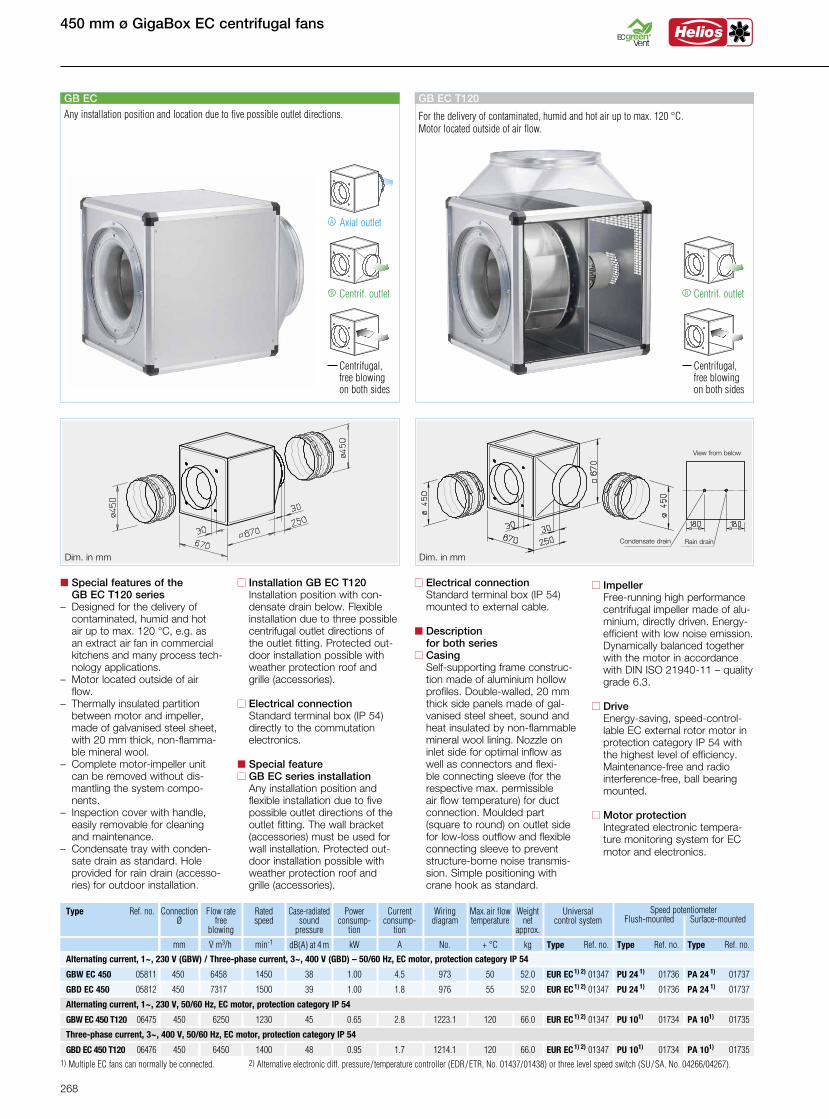
n Installation GB EC T120 Installation position with con-
densate drain below. Flexible installation due to three possible centrifugal outlet directions of the outlet fitting. Protected out-door installation possible with weather protection roof and grille (accessories).
n Electrical connection Standard terminal box (IP 54) directly to the commutation electronics.
n Special featuren GB EC series installation Any installation position and
flexible installation due to five possible outlet directions of the outlet fitting. The wall bracket (accessories) must be used for wall installation. Protected out-door installation possible with weather protection roof and grille (accessories).
n Special features of the GB EC T120 series– Designed for the delivery of
contaminated, humid and hot air up to max. 120 °C, e.g. as an extract air fan in commercial kitchens and many process tech-nology applications.
– Motor located outside of air flow.
– Thermally insulated partition between motor and impeller, made of galvanised steel sheet, with 20 mm thick, non-flamma- ble mineral wool.– Complete motor-impeller unit
can be removed without dis-mantling the system compo-nents.
– Inspection cover with handle, easily removable for cleaning and maintenance.
– Condensate tray with conden-sate drain as standard. Hole provided for rain drain (accesso-ries) for outdoor installation.
n Electrical connection Standard terminal box (IP 54) mounted to external cable.
n Description for both seriesn Casing Self-supporting frame construc-
tion made of aluminium hollow profiles. Double-walled, 20 mm thick side panels made of gal-vanised steel sheet, sound and heat insulated by non-flammable mineral wool lining. Nozzle on inlet side for optimal inflow as well as connectors and flexi-ble connecting sleeve (for the respective max. permissible air flow temperature) for duct connection. Moulded part (square to round) on outlet side for low-loss outflow and flexible connecting sleeve to prevent structure-borne noise transmis-sion. Simple positioning with crane hook as standard.
n Impeller Free-running high performance
centrifugal impeller made of alu-minium, directly driven. Energy-
efficient with low noise emission. Dynamically balanced together with the motor in accordance with DIN ISO 21940-11 – quality grade 6.3.
n Drive Energy-saving, speed-control-
lable EC external rotor motor in protection category IP 54 with the highest level of efficiency. Maintenance-free and radio interference-free, ball bearing mounted.
n Motor protection Integrated electronic tempera-ture monitoring system for EC motor and electronics.
View from below
Condensate drain Rain drain
268
GigaBox EC centrifugal fans 450 mm ø
n Accessories for both series
Vibration dampers for indoor in-stallation. 1 set = 4 pcs.SDD-U Ref. no. 05627 Wall bracket for wall installation.GB-WK 450 Ref. no. 05626
Weather protection grille for out-let-side coverage.GB-WSG 450 Ref. no. 05639
Weather protection roof for pro-tected outdoor installation.GB-WSD 450 Ref. no. 05748
n Special accessories
n for GB EC seriesCondensate tray with drain con-nectors (central) for duct/hoseconnection.GB-KW 450 Ref. no. 05644(a condensate tray with conden-sate drain is included in delivery for GB EC T120).
n for GB EC T120 seriesRain drain for outdoor installation(Hole in casing base already pro-vided).GB-RA Ref. no. 09418
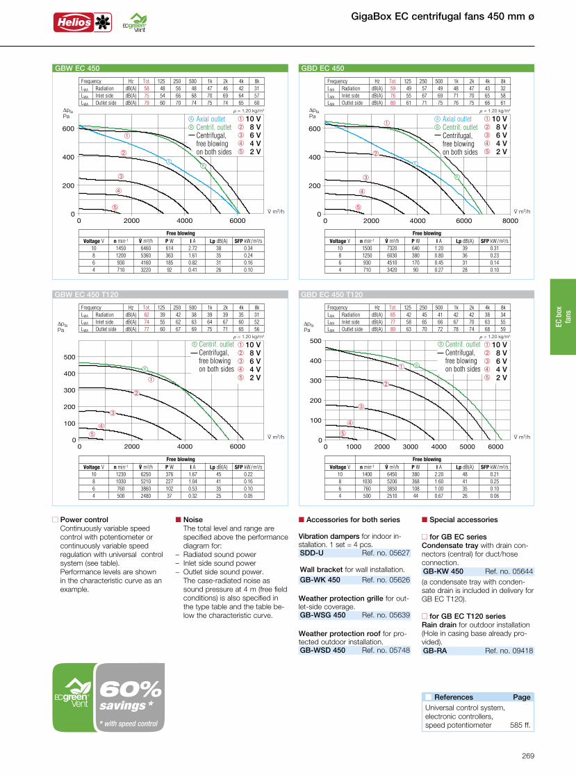
Frequency Hz Tot. 125 250 500 1k 2k 4k 8k LWA Radiation dB(A) 59 49 57 49 48 47 43 32 LWA Inlet side dB(A) 76 55 67 69 71 70 65 58 LWA Outlet side dB(A) 80 61 71 75 76 75 66 61
á
û
ô
ê
â
V· m3/h
DpfaPa
r = 1.20 kg/m3
GBD EC 450
â 10 Vê 8 Vô 6 V û 4 V á 2 V
Axial outlet Centrif. outlet Centrifugal,
free blowing on both sides
Free blowing Voltage V n min-1 V· m3/h P W I A Lp dB(A) SFP kW/m3/s 10 1500 7320 640 1.20 39 0.31 8 1250 6030 380 0.80 36 0.23 6 930 4510 170 0.45 31 0.14 4 710 3420 90 0.27 28 0.10
R
A
R
A
Frequency Hz Tot. 125 250 500 1k 2k 4k 8k LWA Radiation dB(A) 62 39 42 38 39 39 35 31 LWA Inlet side dB(A) 74 55 62 63 64 67 60 52 LWA Outlet side dB(A) 77 60 67 69 75 71 65 56
V· m3/h
DpfaPa
r = 1.20 kg/m3
áû
ô
ê
â
GBW EC 450 T120
Free blowing Voltage V n min-1 V· m3/h P W I A Lp dB(A) SFP kW/m3/s 10 1230 6250 376 1.67 45 0.22 8 1030 5210 227 1.04 41 0.16 6 760 3860 102 0.53 35 0.10 4 500 2480 37 0.32 25 0.05
R
Centrif. outlet Centrifugal,
free blowing on both sides
R â 10 Vê 8 Vô 6 V û 4 V á 2 V
Frequency Hz Tot. 125 250 500 1k 2k 4k 8k LWA Radiation dB(A) 65 42 45 41 42 42 38 34 LWA Inlet side dB(A) 77 58 65 66 67 70 63 55 LWA Outlet side dB(A) 80 63 70 72 78 74 68 59
R
V· m3/h
DpfaPa
r = 1.20 kg/m3
á
û
ô
ê
â
GBD EC 450 T120
Free blowing Voltage V n min-1 V· m3/h P W I A Lp dB(A) SFP kW/m3/s 10 1400 6450 380 2.20 48 0.21 8 1030 5200 368 1.60 41 0.25 6 760 3850 108 1.00 35 0.10 4 500 2510 44 0.67 26 0.06
Centrif. outlet Centrifugal,
free blowing on both sides
R â 10 Vê 8 Vô 6 V û 4 V á 2 V
n References Page Universal control system,electronic controllers,speed potentiometer 585 ff.
n Power control Continuously variable speed control with potentiometer or continuously variable speed regulation with universal control system (see table).
Performance levels are shown in the characteristic curve as an example.
n Noise The total level and range are specified above the performance diagram for:
– Radiated sound power– Inlet side sound power– Outlet side sound power.
The case-radiated noise as sound pressure at 4 m (free field conditions) is also specified in the type table and the table be-low the characteristic curve.
Frequency Hz Tot. 125 250 500 1k 2k 4k 8k LWA Radiation dB(A) 58 48 56 48 47 46 42 31 LWA Inlet side dB(A) 75 54 66 68 70 69 64 57 LWA Outlet side dB(A) 79 60 70 74 75 74 65 60
á
û
ô
ê
â
V· m3/h
DpfaPa
r = 1.20 kg/m3
GBW EC 450
â 10 Vê 8 Vô 6 V û 4 V á 2 V
Axial outlet Centrif. outlet Centrifugal,
free blowing on both sides
Free blowing Voltage V n min-1 V· m3/h P W I A Lp dB(A) SFP kW/m3/s 10 1450 6460 614 2.72 38 0.34 8 1200 5360 363 1.61 35 0.24 6 930 4160 185 0.82 31 0.16 4 710 3220 92 0.41 26 0.10
R
A
RA
savings ** with speed control
269
EC b
ox
fans

500 mm ø GigaBox EC centrifugal fans
Centrif. outlet
Centrifugal, free blowing on both sides
R
GB EC T120
For the delivery of contaminated, humid and hot air up to max. 120 °C. Motor located outside of air flow.
Axial outletA
Centrif. outlet
Centrifugal, free blowing on both sides
GB EC
R
Any installation position and location due to five possible outlet directions.
Connection Ø
Flow ratefree
blowing
Type Ref. no. Ratedspeed
Case-radiated sound
pressure
Wiringdiagram
Weight net
approx.
mm.V m3/h min-1 dB(A) at 4 m No. kg
Powerconsump-
tion
kW
Current consump-
tion
A
Max. air flowtemperature
+ °C
Universal control system
Speed potentiometer Flush-mounted Surface-mounted
Type Ref. no. Type Ref. no. Type Ref. no.
GBD EC 500 A T120 06477 500 9850 1400 51 1214.1 96.01.45 2,4 120 EUR EC1) 2) 01347 PU 101) 01734 PA 101) 01735
GBD EC 500 A 05818 500 8280 1200 43 976 80.51.10 1.80 50 EUR EC1) 2) 01347 PU 24 1) 01736 PA 24 1) 01737
GBD EC 500 B 05813 500 10500 1500 46 976 79.01.95 3.10 50 EUR EC1) 2) 01347 PU 24 1) 01736 PA 24 1) 01737
Three-phase current, 3~, 400 V, 50/60 Hz, EC motor, protection category IP 54
Three-phase current, 3~, 400 V, 50/60 Hz, EC motor, protection category IP 54
1) Multiple EC fans can normally be connected. 2) Alternative electronic diff. pressure / temperature controller (EDR/ETR, No. 01437/01438) or three level speed switch (SU/SA, No. 04266/04267).
Dim. in mm Dim. in mm
n Installation GB EC T120 Installation position with con-
densate drain below. Flexible installation due to three possible centrifugal outlet directions of the outlet fitting. Protected out-door installation possible with weather protection roof and grille (accessories).
n Electrical connection Standard terminal box (IP 54) directly to the commutation electronics.
n Special featuren GB EC series installation Any installation position and
flexible installation due to five possible outlet directions of the outlet fitting. The wall bracket (accessories) must be used for wall installation. Protected out-door installation possible with weather protection roof and grille (accessories).
n Special features of the GB EC T120 series– Designed for the delivery of
contaminated, humid and hot air up to max. 120 °C, e.g. as an extract air fan in commercial kitchens and many process tech-nology applications.
– Motor located outside of air flow.
– Thermally insulated partition between motor and impeller, made of galvanised steel sheet, with 20 mm thick, non-flamma- ble mineral wool.– Complete motor-impeller unit
can be removed without dis-mantling the system compo-nents.
– Inspection cover with handle, easily removable for cleaning and maintenance.
– Condensate tray with conden-sate drain as standard. Hole provided for rain drain (accesso-ries) for outdoor installation.
n Electrical connection Standard terminal box (IP 54) mounted to external cable.
n Description for both seriesn Casing Self-supporting frame construc-
tion made of aluminium hollow profiles. Double-walled, 20 mm thick side panels made of gal-vanised steel sheet, sound and heat insulated by non-flammable mineral wool lining. Nozzle on inlet side for optimal inflow as well as connectors and flexi-ble connecting sleeve (for the respective max. permissible air flow temperature) for duct connection. Moulded part (square to round) on outlet side for low-loss outflow and flexible connecting sleeve to prevent structure-borne noise transmis-sion. Simple positioning with crane hook as standard.
n Impeller Free-running high performance
centrifugal impeller made of alu-minium, directly driven. Energy-
efficient with low noise emission. Dynamically balanced together with the motor in accordance with DIN ISO 21940-11 – quality grade 6.3.
n Drive Energy-saving, speed-control-
lable EC external rotor motor in protection category IP 54 with the highest level of efficiency. Maintenance-free and radio interference-free, ball bearing mounted.
n Motor protection Integrated electronic tempera-ture monitoring system for EC motor and electronics.
View from below
Condensate drain Rain drain
270
GigaBox EC centrifugal fans 500 mm ø
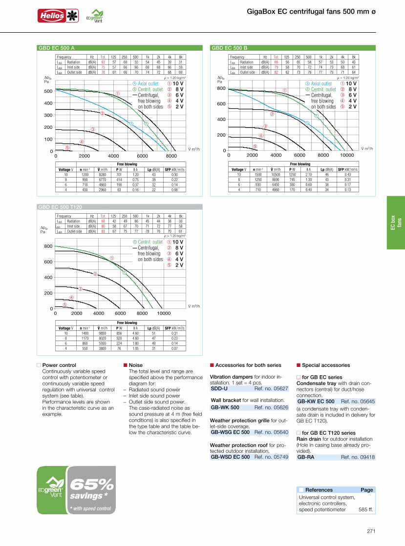
Frequency Hz Tot. 125 250 500 1k 2k 4k 8k LWA Radiation dB(A) 63 57 60 55 54 45 39 31 LWA Inlet side dB(A) 75 57 66 66 69 68 66 59 LWA Outlet side dB(A) 78 61 66 70 74 72 68 60
áû
ô
ê
â
V· m3/h
DpfaPa
r = 1.20 kg/m3
GBD EC 500 A
â 10 Vê 8 Vô 6 V û 4 V á 2 V
Axial outlet Centrif. outlet Centrifugal,
free blowing on both sides
R
A
RA
Free blowing Voltage V n min-1 V· m3/h P W I A Lp dB(A) SFP kW/m3/s 10 1200 8280 701 1.20 43 0.30 8 990 6770 414 0.75 39 0.22 6 710 4860 190 0.37 32 0.14 4 430 2960 63 0.16 22 0.08
Frequency Hz Tot. 125 250 500 1k 2k 4k 8k LWA Radiation dB(A) 66 56 65 58 57 53 50 43 LWA Inlet side dB(A) 79 58 70 72 74 73 68 61 LWA Outlet side dB(A) 82 62 73 76 77 75 71 64
á
û
ô
ê
â
V· m3/h
DpfaPa
r = 1.20 kg/m3
GBD EC 500 B
â 10 Vê 8 Vô 6 V û 4 V á 2 V
Axial outlet Centrif. outlet Centrifugal,
free blowing on both sides
R
A
R
A
Free blowing Voltage V n min-1 V· m3/h P W I A Lp dB(A) SFP kW/m3/s 10 1500 10500 1250 2.10 46 0.43 8 1250 8690 745 1.30 43 0.31 6 930 6450 300 0.60 38 0.17 4 710 4860 170 0.40 34 0.13
n Accessories for both series
Vibration dampers for indoor in-stallation. 1 set = 4 pcs.SDD-U Ref. no. 05627 Wall bracket for wall installation.GB-WK 500 Ref. no. 05626
Weather protection grille for out-let-side coverage.GB-WSG EC 500 Ref. no. 05640
Weather protection roof for pro-tected outdoor installation.GB-WSD EC 500 Ref. no. 05749
n Special accessories
n for GB EC seriesCondensate tray with drain con-nectors (central) for duct/hoseconnection.GB-KW EC 500 Ref. no. 05645(a condensate tray with conden-sate drain is included in delivery for GB EC T120).
n for GB EC T120 seriesRain drain for outdoor installation(Hole in casing base already pro-vided).GB-RA Ref. no. 09418
Frequency Hz Tot. 125 250 500 1k 2k 4k 8k LWA Radiation dB(A) 68 42 49 66 45 44 38 30 LWA Inlet side dB(A) 80 58 67 70 71 72 77 58 LWA Outlet side dB(A) 83 67 75 77 78 76 70 61
V· m3/h
DpfaPa
r = 1.20 kg/m3
á
û
ô
ê
â
GBD EC 500 T120
Free blowing Voltage V n min-1 V· m3/h P W I A Lp dB(A) SFP kW/m3/s 10 1400 9850 856 4.60 51 0.31 8 1170 8020 520 4.60 47 0.23 6 860 5930 224 1.80 40 0.14 4 550 3800 76 1.05 31 0.07
R
Centrif. outlet Centrifugal,
free blowing on both sides
R â 10 Vê 8 Vô 6 V û 4 V á 2 V
n Power control Continuously variable speed control with potentiometer or continuously variable speed regulation with universal control system (see table).
Performance levels are shown in the characteristic curve as an example.
n Noise The total level and range are specified above the performance diagram for:
– Radiated sound power– Inlet side sound power– Outlet side sound power.
The case-radiated noise as sound pressure at 4 m (free field conditions) is also specified in the type table and the table be-low the characteristic curve.
n References Page Universal control system,electronic controllers,speed potentiometer 585 ff.
savings ** with speed control
271
EC b
ox
fans

560 mm ø GigaBox EC centrifugal fans
Centrif. outlet
Centrifugal, free blowing on both sides
R
GB EC T120
For the delivery of contaminated, humid and hot air up to max. 120 °C. Motor located outside of air flow.
Axial outletA
Centrif. outlet
Centrifugal, free blowing on both sides
GB EC
R
Any installation position and location due to five possible outlet directions.
Connection Ø
Flow ratefree
blowing
GBD EC 560 05814 560 13367 1400 49 976 83.02.80 4.30 50 EUR EC1) 2) 01347 PU 241) 01736
Type Ref. no. Ratedspeed
Case-radiated sound
pressure
Wiringdiagram
Weight net
approx.
mm.V m3/h min-1 dB(A) at 4 m No. kg
Powerconsump-
tion
kW
Current consump-
tion
A
Max. air flowtemperature
+ °C
Universal control system
Speed potentiometer Flush-mounted Surface-mounted
Type Ref. no. Type Ref. no.
PA 241) 01737
Type Ref. no.
Three-phase current, 3~, 400 V, 50/60 Hz, EC motor, protection category IP 54
GBD EC 560 T120 06481 560 12100 1400 53 1214.1 102.02.30 3.60 120 EUR EC1) 2) 01347 PU 101) 01734 PA 101) 01735
Three-phase current, 3~, 400 V, 50/60 Hz, EC motor, protection category IP 54
Dim. in mm Dim. in mm
1) Multiple EC fans can normally be connected. 2) Alternative electronic diff. pressure / temperature controller (EDR/ETR, No. 01437/01438) or three level speed switch (SU/SA, No. 04266/04267).
n Installation GB EC T120 Installation position with con-
densate drain below. Flexible installation due to three possible centrifugal outlet directions of the outlet fitting. Protected out-door installation possible with weather protection roof and grille (accessories).
n Electrical connection Standard terminal box (IP 54) directly to the commutation electronics.
n Special featuren GB EC series installation Any installation position and
flexible installation due to five possible outlet directions of the outlet fitting. The wall bracket (accessories) must be used for wall installation. Protected out-door installation possible with weather protection roof and grille (accessories).
n Special features of the GB EC T120 series– Designed for the delivery of
contaminated, humid and hot air up to max. 120 °C, e.g. as an extract air fan in commercial kitchens and many process tech-nology applications.
– Motor located outside of air flow.
– Thermally insulated partition between motor and impeller, made of galvanised steel sheet, with 20 mm thick, non-flamma- ble mineral wool.– Complete motor-impeller unit
can be removed without dis-mantling the system compo-nents.
– Inspection cover with handle, easily removable for cleaning and maintenance.
– Condensate tray with conden-sate drain as standard. Hole provided for rain drain (accesso-ries) for outdoor installation.
n Electrical connection Standard terminal box (IP 54) mounted to external cable.
n Description for both seriesn Casing Self-supporting frame construc-
tion made of aluminium hollow profiles. Double-walled, 20 mm thick side panels made of gal-vanised steel sheet, sound and heat insulated by non-flammable mineral wool lining. Nozzle on inlet side for optimal inflow as well as connectors and flexi-ble connecting sleeve (for the respective max. permissible air flow temperature) for duct connection. Moulded part (square to round) on outlet side for low-loss outflow and flexible connecting sleeve to prevent structure-borne noise transmis-sion. Simple positioning with crane hook as standard.
n Impeller Free-running high performance
centrifugal impeller made of alu-minium, directly driven. Energy-
efficient with low noise emission. Dynamically balanced together with the motor in accordance with DIN ISO 21940-11 – quality grade 6.3.
n Drive Energy-saving, speed-control-
lable EC external rotor motor in protection category IP 54 with the highest level of efficiency. Maintenance-free and radio interference-free, ball bearing mounted.
n Motor protection Integrated electronic tempera-ture monitoring system for EC motor and electronics.
View from below
Condensate drain Rain drain
272
GigaBox EC centrifugal fans 560 mm ø
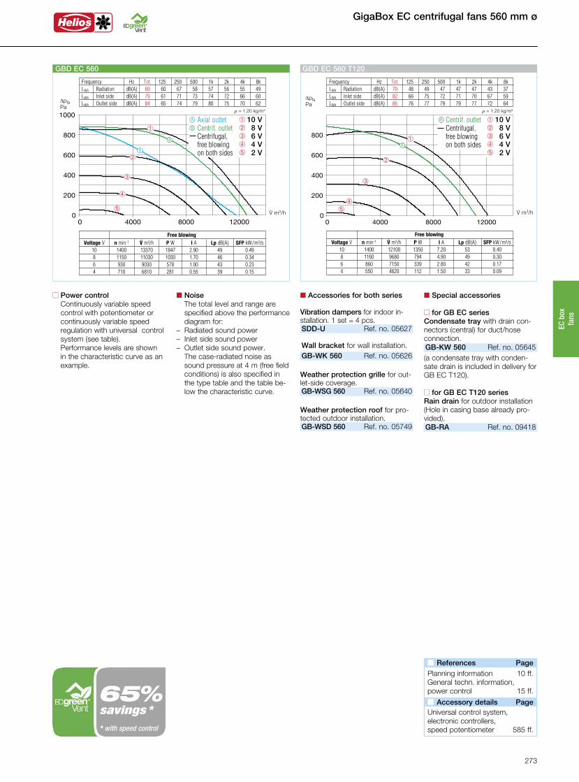
Frequency Hz Tot. 125 250 500 1k 2k 4k 8k LWA Radiation dB(A) 69 60 67 58 57 56 55 49 LWA Inlet side dB(A) 79 61 71 73 74 72 66 60 LWA Outlet side dB(A) 84 65 74 79 80 75 70 62
á
û
ô
ê
â
V· m3/h
DpfaPa
r = 1.20 kg/m3
GBD EC 560
â 10 Vê 8 Vô 6 V û 4 V á 2 V
Axial outlet Centrif. outlet Centrifugal,
free blowing on both sides
Free blowing Voltage V n min-1 V· m3/h P W I A Lp dB(A) SFP kW/m3/s 10 1400 13370 1847 2.90 49 0.49 8 1150 11030 1030 1.70 46 0.34 6 930 9030 578 1.00 43 0.23 4 710 6810 281 0.55 39 0.15
R
A
R
A
n Accessories for both series
Vibration dampers for indoor in-stallation. 1 set = 4 pcs.SDD-U Ref. no. 05627 Wall bracket for wall installation.GB-WK 560 Ref. no. 05626
Weather protection grille for out-let-side coverage.GB-WSG 560 Ref. no. 05640
Weather protection roof for pro-tected outdoor installation.GB-WSD 560 Ref. no. 05749
n Special accessories
n for GB EC seriesCondensate tray with drain con-nectors (central) for duct/hoseconnection.GB-KW 560 Ref. no. 05645(a condensate tray with conden-sate drain is included in delivery for GB EC T120).
n for GB EC T120 seriesRain drain for outdoor installation(Hole in casing base already pro-vided).GB-RA Ref. no. 09418
Frequency Hz Tot. 125 250 500 1k 2k 4k 8k LWA Radiation dB(A) 70 48 49 47 47 47 43 37 LWA Inlet side dB(A) 82 66 75 72 71 70 67 59 LWA Outlet side dB(A) 85 76 77 79 79 77 72 64
V· m3/h
DpfaPa
r = 1.20 kg/m3
áû
ô
ê
â
GBD EC 560 T120
Free blowing Voltage V n min-1 V· m3/h P W I A Lp dB(A) SFP kW/m3/s 10 1400 12100 1350 7.20 53 0.40 8 1160 9680 794 4.90 49 0.30 6 860 7150 339 2.80 42 0.17 4 550 4620 112 1.50 33 0.09
R
Centrif. outlet Centrifugal,
free blowing on both sides
R â 10 Vê 8 Vô 6 V û 4 V á 2 V
n Power control Continuously variable speed control with potentiometer or continuously variable speed regulation with universal control system (see table).
Performance levels are shown in the characteristic curve as an example.
n Noise The total level and range are specified above the performance diagram for:
– Radiated sound power– Inlet side sound power– Outlet side sound power.
The case-radiated noise as sound pressure at 4 m (free field conditions) is also specified in the type table and the table be-low the characteristic curve.
n References Page Planning information 10 ff.General techn. information,power control 15 ff.
n Accessory details Page Universal control system,electronic controllers,speed potentiometer 585 ff.
savings ** with speed control
273
EC b
ox
fans
630 mm ø GigaBox EC centrifugal fans
1) Multiple EC fans can normally be connected. 2) Alternative electronic diff. pressure / temperature controller (EDR/ETR, No. 01437/01438) or three level speed switch (SU/SA, No. 04266/04267).
Centrif. outlet
Centrifugal, free blowing on both sides
R
GB EC T120
For the delivery of contaminated, humid and hot air up to max. 120 °C. Motor located outside of air flow.
Axial outletA
Centrif. outlet
Centrifugal, free blowing on both sides
GB EC
R
Any installation position and location due to five possible outlet directions.
Dim. in mm Dim. in mm
Connection Ø
Flow ratefree
blowing
GBD EC 630 05815 630 15000 1100 44 976 116.02.30 3.70 50 EUR EC1) 2) 01347 PU 241) 01736
Type Ref. no. Ratedspeed
Case-radiated sound
pressure
Wiringdiagram
Weight net
approx.
mm.V m3/h min-1 dB(A) at 4 m No. kg
Powerconsump-
tion
kW
Current consump-
tion
A
Max. air flowtemperature
+ °C
Universal control system
Speed potentiometer Flush-mounted Surface-mounted
Type Ref. no. Type Ref. no.
PA 241) 01737
Type Ref. no.
GBD EC 630 T120 06485 630 15300 1350 54 1214.1 112.03.60 5.50 120 EUR EC1) 2) 01347 PU 101) 01734 PA 101) 01735
Three-phase current, 3~, 400 V, 50/60 Hz, EC motor, protection category IP 54
Three-phase current, 3~, 400 V, 50/60 Hz, EC motor, protection category IP 54
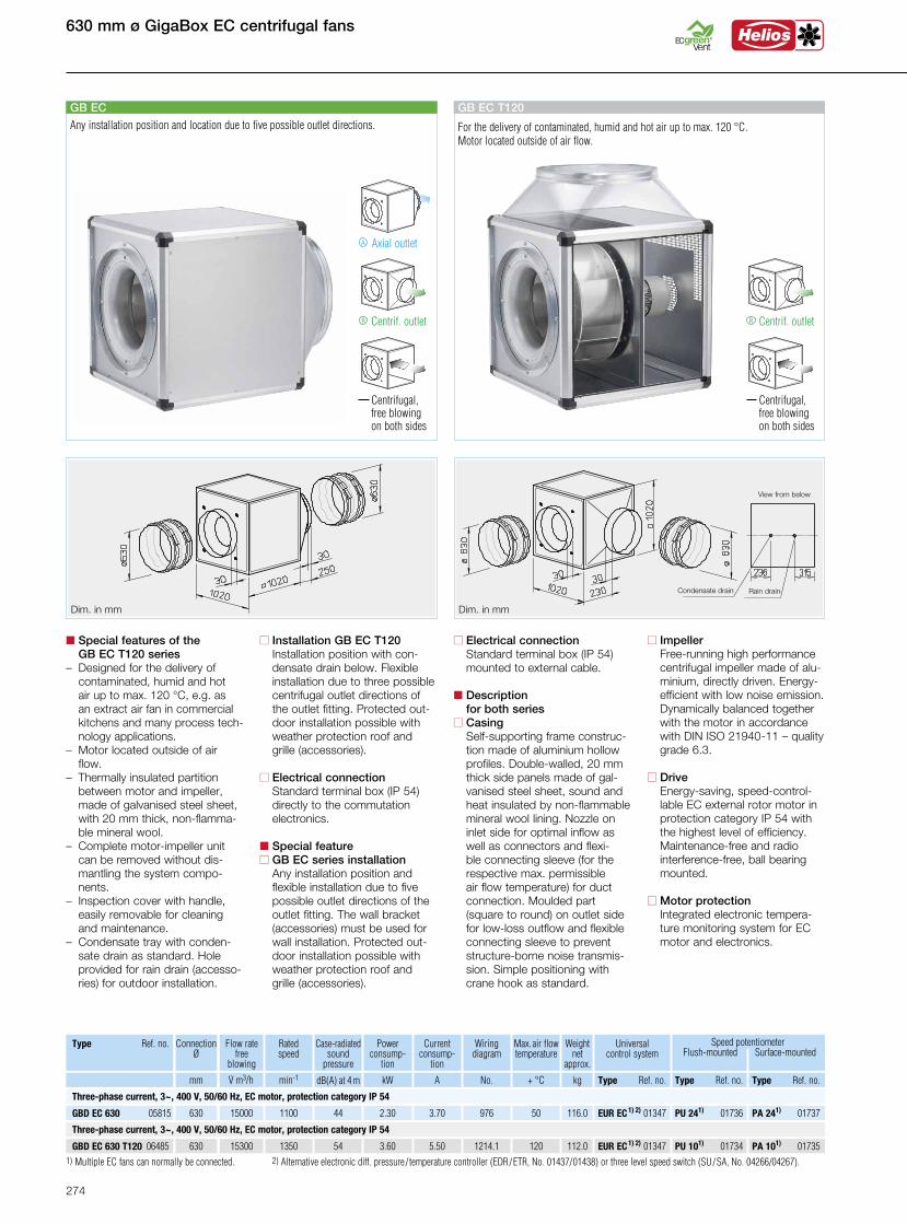
n Installation GB EC T120 Installation position with con-
densate drain below. Flexible installation due to three possible centrifugal outlet directions of the outlet fitting. Protected out-door installation possible with weather protection roof and grille (accessories).
n Electrical connection Standard terminal box (IP 54) directly to the commutation electronics.
n Special featuren GB EC series installation Any installation position and
flexible installation due to five possible outlet directions of the outlet fitting. The wall bracket (accessories) must be used for wall installation. Protected out-door installation possible with weather protection roof and grille (accessories).
n Special features of the GB EC T120 series– Designed for the delivery of
contaminated, humid and hot air up to max. 120 °C, e.g. as an extract air fan in commercial kitchens and many process tech-nology applications.
– Motor located outside of air flow.
– Thermally insulated partition between motor and impeller, made of galvanised steel sheet, with 20 mm thick, non-flamma- ble mineral wool.– Complete motor-impeller unit
can be removed without dis-mantling the system compo-nents.
– Inspection cover with handle, easily removable for cleaning and maintenance.
– Condensate tray with conden-sate drain as standard. Hole provided for rain drain (accesso-ries) for outdoor installation.
n Electrical connection Standard terminal box (IP 54) mounted to external cable.
n Description for both seriesn Casing Self-supporting frame construc-
tion made of aluminium hollow profiles. Double-walled, 20 mm thick side panels made of gal-vanised steel sheet, sound and heat insulated by non-flammable mineral wool lining. Nozzle on inlet side for optimal inflow as well as connectors and flexi-ble connecting sleeve (for the respective max. permissible air flow temperature) for duct connection. Moulded part (square to round) on outlet side for low-loss outflow and flexible connecting sleeve to prevent structure-borne noise transmis-sion. Simple positioning with crane hook as standard.
n Impeller Free-running high performance
centrifugal impeller made of alu-minium, directly driven. Energy-
efficient with low noise emission. Dynamically balanced together with the motor in accordance with DIN ISO 21940-11 – quality grade 6.3.
n Drive Energy-saving, speed-control-
lable EC external rotor motor in protection category IP 54 with the highest level of efficiency. Maintenance-free and radio interference-free, ball bearing mounted.
n Motor protection Integrated electronic tempera-ture monitoring system for EC motor and electronics.
View from below
Condensate drain Rain drain
274

GigaBox EC centrifugal fans 630 mm ø
Frequency Hz Tot. 125 250 500 1k 2k 4k 8k LWA Radiation dB(A) 64 58 61 53 53 51 49 41 LWA Inlet side dB(A) 80 66 71 72 74 73 72 68 LWA Outlet side dB(A) 83 69 76 77 78 75 68 61
á
û
ô
ê
â
V· m3/h
DpfaPa
r = 1.20 kg/m3
GBD EC 630
â 10 Vê 8 Vô 6 V û 4 V á 2 V
Axial outlet Centrif. outlet Centrifugal,
free blowing on both sides
R
A
R
A
Free blowing Voltage V n min-1 V· m3/h P W I A Lp dB(A) SFP kW/m3/s 10 1100 15000 1430 2.40 44 0.34 8 930 12610 890 1.50 42 0.25 6 710 9600 415 0.78 38 0.16 4 500 6880 170 0.36 32 0.09
n Accessories for both series
Vibration dampers for indoor in-stallation. 1 set = 4 pcs.SDD-U Ref. no. 05627 Wall bracket for wall installation.GB-WK 630 Ref. no. 05626
Weather protection grille for out-let-side coverage.GB-WSG 630 Ref. no. 05640
Weather protection roof for pro-tected outdoor installation.GB-WSD 630 Ref. no. 05749
n Special accessories
n for GB EC seriesCondensate tray with drain con-nectors (central) for duct/hoseconnection.GB-KW EC 630 Ref. no. 05646(a condensate tray with conden-sate drain is included in delivery for GB EC T120).
n for GB EC T120 seriesRain drain for outdoor installation(Hole in casing base already pro-vided).GB-RA Ref. no. 09418
Frequency Hz Tot. 125 250 500 1k 2k 4k 8k LWA Radiation dB(A) 71 45 49 45 49 44 37 28 LWA Inlet side dB(A) 85 59 70 71 76 79 74 64 LWA Outlet side dB(A) 88 70 70 80 83 83 79 67
R
V· m3/h
DpfaPa
r = 1.20 kg/m3
á
û
ô
ê
â
GBD EC 630 T120
Centrif. outlet Centrifugal,
free blowing on both sides
R
Free blowing Voltage V n min-1 V· m3/h P W I A Lp dB(A) SFP kW/m3/s 10 1350 15300 2250 11.90 54 0.53 8 1130 12200 1320 8.30 50 0.39 6 830 8970 560 1.50 43 0.22 4 540 5810 180 2.30 34 0.11
â 10 Vê 8 Vô 6 V û 4 V á 2 V
n References Page Planning information 10 ff.General techn. information,power control 15 ff.
n Accessory details Page Universal control system,electronic controllers,speed potentiometer 585 ff.
n Power control Continuously variable speed control with potentiometer or continuously variable speed regulation with universal control system (see table).
Performance levels are shown in the characteristic curve as an example.
n Noise The total level and range are specified above the performance diagram for:
– Radiated sound power– Inlet side sound power– Outlet side sound power.
The case-radiated noise as sound pressure at 4 m (free field conditions) is also specified in the type table and the table be-low the characteristic curve.
savings ** with speed control
275
EC b
ox
fans
710 mm ø GigaBox EC centrifugal fans
Connection Ø
Flow ratefree
blowing
Type Ref. no. Ratedspeed
Case-radiated sound
pressure
Wiringdiagram
Weight net
approx.
mm.V m3/h min-1 dB(A) at 4 m No. kg
Powerconsump-
tion
kW
Current consump-
tion
A
Max. air flowtemperature
+ °C
Universal control system
Speed potentiometer Flush-mounted Surface-mounted
Type Ref. no. Type Ref. no. Type Ref. no.
GBD EC 710 T120 06488 710 18360 1380 51 1214.1 207.04.63 7.80 120 EUR EC1) 2) 01347 PU 101) 01734 PA 101) 01735
GBD EC 710 A 05816 710 15892 775 42 976 119.01.50 2.40 50 EUR EC1) 2) 01347 PU 24 1) 01736 PA 24 1) 01737
GBD EC 710 B 05819 710 19650 940 48 976 100.02.65 4.10 50 EUR EC1) 2) 01347 PU 24 1) 01736 PA 24 1) 01737
Three-phase current, 3~, 400 V, 50/60 Hz, EC motor, protection category IP 54
Three-phase current, 3~, 400 V, 50/60 Hz, EC motor, protection category IP 54
1) Multiple EC fans can normally be connected. 2) Alternative electronic diff. pressure / temperature controller (EDR/ETR, No. 01437/01438) or three level speed switch (SU/SA, No. 04266/04267).
Centrif. outlet
Centrifugal, free blowing on both sides
R
GB EC T120
For the delivery of contaminated, humid and hot air up to max. 120 °C. Motor located outside of air flow.
Axial outletA
Centrif. outlet
Centrifugal, free blowing on both sides
GB EC
R
Any installation position and location due to five possible outlet directions.
Dim. in mm Dim. in mm
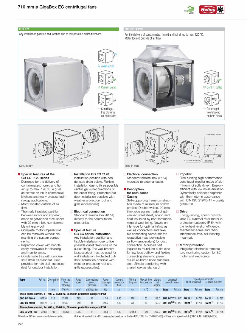
n Installation GB EC T120 Installation position with con-
densate drain below. Flexible installation due to three possible centrifugal outlet directions of the outlet fitting. Protected out-door installation possible with weather protection roof and grille (accessories).
n Electrical connection Standard terminal box (IP 54) directly to the commutation electronics.
n Special featuren GB EC series installation Any installation position and
flexible installation due to five possible outlet directions of the outlet fitting. The wall bracket (accessories) must be used for wall installation. Protected out-door installation possible with weather protection roof and grille (accessories).
n Special features of the GB EC T120 series– Designed for the delivery of
contaminated, humid and hot air up to max. 120 °C, e.g. as an extract air fan in commercial kitchens and many process tech-nology applications.
– Motor located outside of air flow.
– Thermally insulated partition between motor and impeller, made of galvanised steel sheet, with 20 mm thick, non-flamma- ble mineral wool.– Complete motor-impeller unit
can be removed without dis-mantling the system compo-nents.
– Inspection cover with handle, easily removable for cleaning and maintenance.
– Condensate tray with conden-sate drain as standard. Hole provided for rain drain (accesso-ries) for outdoor installation.
n Electrical connection Standard terminal box (IP 54) mounted to external cable.
n Description for both seriesn Casing Self-supporting frame construc-
tion made of aluminium hollow profiles. Double-walled, 20 mm thick side panels made of gal-vanised steel sheet, sound and heat insulated by non-flammable mineral wool lining. Nozzle on inlet side for optimal inflow as well as connectors and flexi-ble connecting sleeve (for the respective max. permissible air flow temperature) for duct connection. Moulded part (square to round) on outlet side for low-loss outflow and flexible connecting sleeve to prevent structure-borne noise transmis-sion. Simple positioning with crane hook as standard.
n Impeller Free-running high performance
centrifugal impeller made of alu-minium, directly driven. Energy-
efficient with low noise emission. Dynamically balanced together with the motor in accordance with DIN ISO 21940-11 – quality grade 6.3.
n Drive Energy-saving, speed-control-
lable EC external rotor motor in protection category IP 54 with the highest level of efficiency. Maintenance-free and radio interference-free, ball bearing mounted.
n Motor protection Integrated electronic tempera-ture monitoring system for EC motor and electronics.
View from below
Condensate drain Rain drain
276
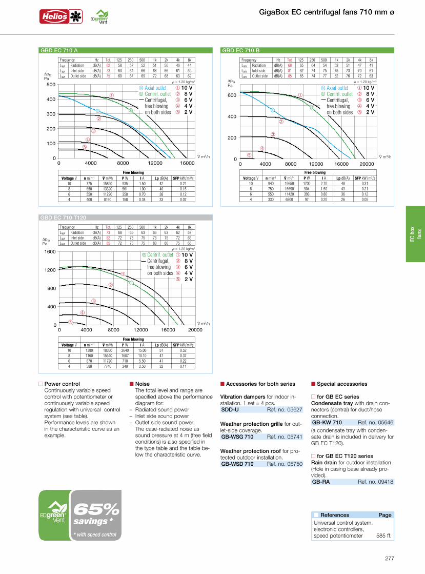
GigaBox EC centrifugal fans 710 mm ø
Frequency Hz Tot. 125 250 500 1k 2k 4k 8k LWA Radiation dB(A) 62 58 57 52 51 50 46 44 LWA Inlet side dB(A) 73 60 64 66 68 66 61 59 LWA Outlet side dB(A) 75 60 67 69 72 68 63 62
á
û
ô
ê
â
V· m3/h
DpfaPa
r = 1.20 kg/m3
GBD EC 710 A
â 10 Vê 8 Vô 6 V û 4 V á 2 V
Axial outlet Centrif. outlet Centrifugal,
free blowing on both sides
R
A
RA
Free blowing Voltage V n min-1 V· m3/h P W I A Lp dB(A) SFP kW/m3/s 10 775 15890 935 1.50 42 0.21 8 650 13320 561 1.00 40 0.15 6 550 11220 358 0.70 38 0.12 4 400 8150 158 0.34 33 0.07
n Accessories for both series
Vibration dampers for indoor in-stallation. 1 set = 4 pcs.SDD-U Ref. no. 05627
Weather protection grille for out-let-side coverage.GB-WSG 710 Ref. no. 05741
Weather protection roof for pro-tected outdoor installation.GB-WSD 710 Ref. no. 05750
n Special accessories
n for GB EC seriesCondensate tray with drain con-nectors (central) for duct/hoseconnection.GB-KW 710 Ref. no. 05646(a condensate tray with conden-sate drain is included in delivery for GB EC T120).
n for GB EC T120 seriesRain drain for outdoor installation(Hole in casing base already pro-vided).GB-RA Ref. no. 09418
Frequency Hz Tot. 125 250 500 1k 2k 4k 8k LWA Radiation dB(A) 73 68 65 63 66 63 62 59 LWA Inlet side dB(A) 82 72 73 75 76 75 72 65 LWA Outlet side dB(A) 85 72 75 75 80 80 75 68
R
V· m3/h
DpfaPa
r = 1.20 kg/m3
á
û
ô
ê
â
GBD EC 710 T120
Free blowing Voltage V n min-1 V· m3/h P W I A Lp dB(A) SFP kW/m3/s 10 1380 18360 2640 15.00 51 0.52 8 1160 15540 1607 10.10 47 0.37 6 870 11720 710 5.50 41 0.22 4 580 7740 240 2.50 32 0.11
Centrif. outlet Centrifugal,
free blowing on both sides
R â 10 Vê 8 Vô 6 V û 4 V á 2 V
n Power control Continuously variable speed control with potentiometer or continuously variable speed regulation with universal control system (see table).
Performance levels are shown in the characteristic curve as an example.
n Noise The total level and range are specified above the performance diagram for:
– Radiated sound power– Inlet side sound power– Outlet side sound power.
The case-radiated noise as sound pressure at 4 m (free field conditions) is also specified in the type table and the table be-low the characteristic curve.
n References Page Universal control system,electronic controllers,speed potentiometer 585 ff.
Frequency Hz Tot. 125 250 500 1k 2k 4k 8k LWA Radiation dB(A) 68 65 64 54 53 51 47 41 LWA Inlet side dB(A) 81 62 74 75 75 73 70 61 LWA Outlet side dB(A) 85 65 74 77 82 76 72 63
áû
ô
ê
â
V· m3/h
DpfaPa
r = 1.20 kg/m3
GBD EC 710 B
RA
Free blowing Voltage V n min-1 V· m3/h P W I A Lp dB(A) SFP kW/m3/s 10 940 19650 1700 2.70 48 0.31 8 750 15690 904 1.50 43 0.21 6 550 11420 393 0.80 36 0.12 4 330 6800 97 0.20 26 0.05
â 10 Vê 8 Vô 6 V û 4 V á 2 V
Axial outlet Centrif. outlet Centrifugal,
free blowing on both sides
R
A
savings ** with speed control
277
EC b
ox
fans
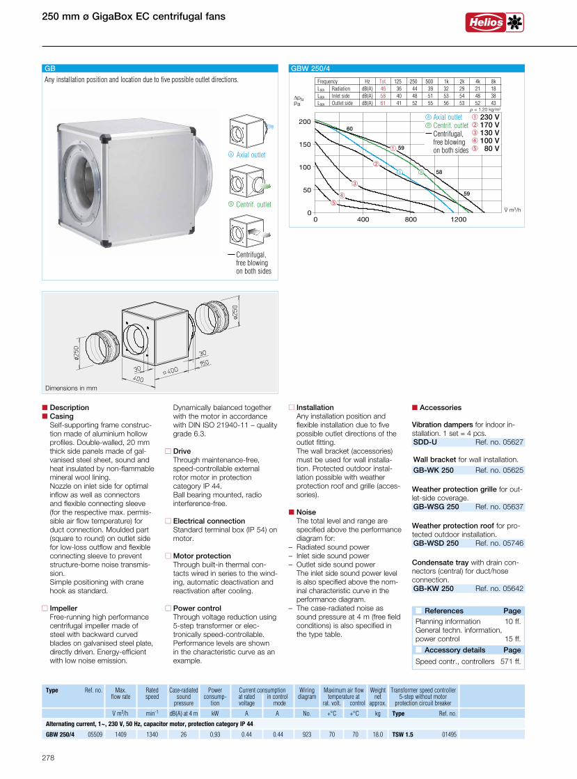
250 mm ø GigaBox EC centrifugal fans
Dynamically balanced together with the motor in accordance with DIN ISO 21940-11 – quality grade 6.3.
n Drive Through maintenance-free,
speed-controllable external rotor motor in protection category IP 44. Ball bearing mounted, radio interference-free.
n Electrical connection Standard terminal box (IP 54) on motor.
n Motor protection Through built-in thermal con-tacts wired in series to the wind-ing, automatic deactivation and reactivation after cooling.
n Power control Through voltage reduction using 5-step transformer or elec- tronically speed-controllable.
Performance levels are shown in the characteristic curve as an example.
n Descriptionn Casing Self-supporting frame construc-
tion made of aluminium hollow profiles. Double-walled, 20 mm thick side panels made of gal-vanised steel sheet, sound and heat insulated by non-flammable mineral wool lining. Nozzle on inlet side for optimal inflow as well as connectors and flexible connecting sleeve (for the respective max. permis-sible air flow temperature) for duct connection. Moulded part (square to round) on outlet side for low-loss outflow and flexible connecting sleeve to prevent structure-borne noise transmis-sion.
Simple positioning with crane hook as standard.
n Impeller Free-running high performance
centrifugal impeller made of steel with backward curved blades on galvanised steel plate, directly driven. Energy-efficient with low noise emission.
Dimensions in mm
n Accessories
Vibration dampers for indoor in-stallation. 1 set = 4 pcs.SDD-U Ref. no. 05627 Wall bracket for wall installation.GB-WK 250 Ref. no. 05625
Weather protection grille for out-let-side coverage.GB-WSG 250 Ref. no. 05637
Weather protection roof for pro-tected outdoor installation.GB-WSD 250 Ref. no. 05746
Condensate tray with drain con-nectors (central) for duct/hoseconnection.GB-KW 250 Ref. no. 05642
n Installation Any installation position and
flexible installation due to five possible outlet directions of the outlet fitting.
The wall bracket (accessories) must be used for wall installa-tion. Protected outdoor instal-lation possible with weather protection roof and grille (acces-sories).
n Noise The total level and range are specified above the performance diagram for:
– Radiated sound power– Inlet side sound power– Outlet side sound power The inlet side sound power level
is also specified above the nom-inal characteristic curve in the performance diagram.
– The case-radiated noise as sound pressure at 4 m (free field conditions) is also specified in the type table.
Transformer speed controller 5-step without motor protection circuit breaker
GBW 250/4 05509 1340 26 0.44 0.44 923 70 70 18.0
Type Ref. no. Max. flow rate
Ratedspeed
Case-radiated sound
pressure
Current consumption at rated in control voltage mode
Wiringdiagram
Maximum air flow temperature at
rat. volt. control
Weight net
approx. .V m3/h min-1 dB(A) at 4 m A A No. +°C +°C kg
0,93
Powerconsump-
tion
kW
TSW 1.5 01495
Type Ref. no.
1409
Alternating current, 1~, 230 V, 50 Hz, capacitor motor, protection category IP 44
n References Page Planning information 10 ff.General techn. information,power control 15 ff.
n Accessory details Page
Speed contr., controllers 571 ff.
Frequency Hz Tot. 125 250 500 1k 2k 4k 8k LWA Radiation dB(A) 46 36 44 39 32 29 21 18 LWA Inlet side dB(A) 58 40 48 51 53 54 48 38 LWA Outlet side dB(A) 61 41 52 55 56 53 52 43
RA
áû
ô
ê
â
V· m3/h
DpfaPa
r = 1,20 kg/m3
60
59
58
59
GBW 250/4
â 230 Vê 170 Vô 130 V û 100 V á 80 V
Axial outlet Centrif. outlet Centrifugal,
free blowing on both sides
R
A
GB
Axial outletA
Centrif. outlet
Centrifugal, free blowing on both sides
R
Any installation position and location due to five possible outlet directions.
278
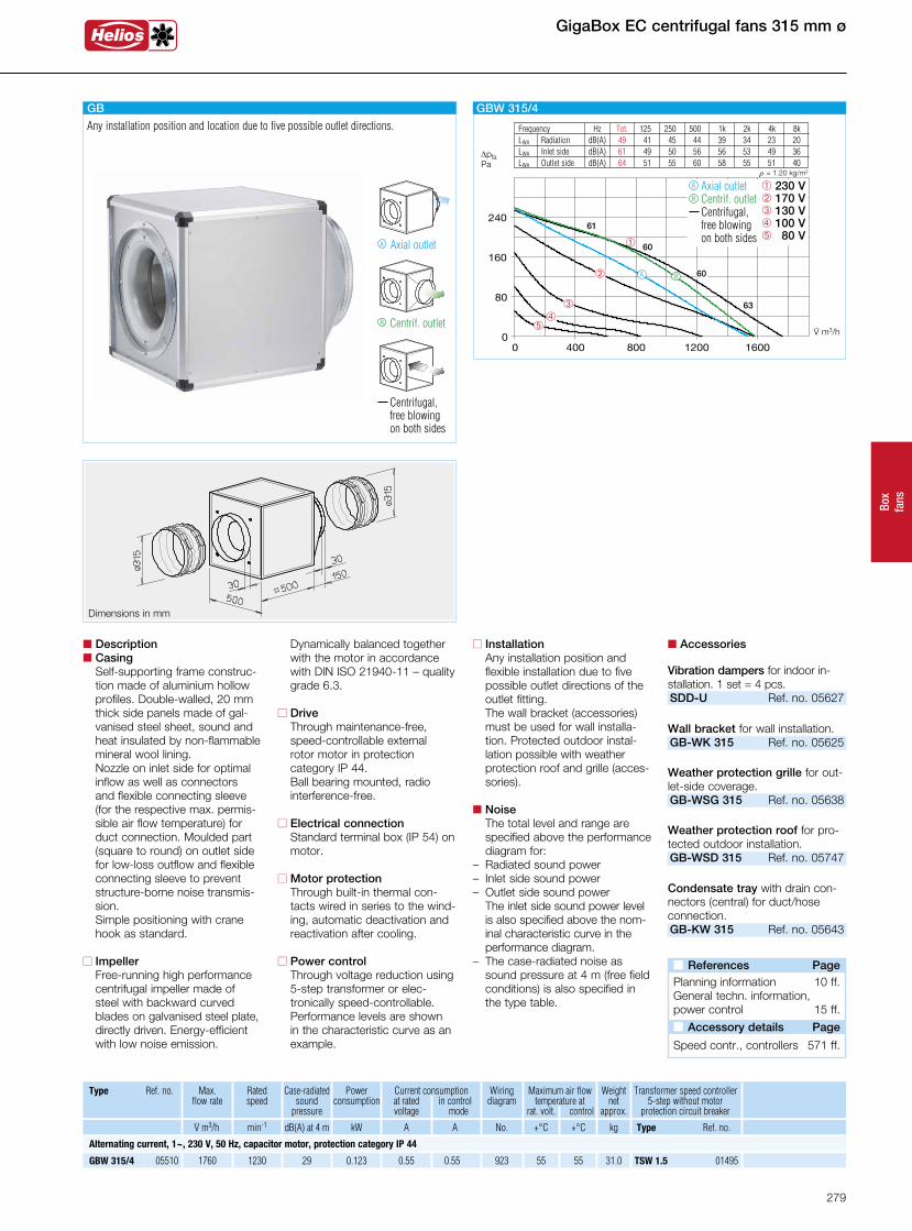
Box
fans
Dimensions in mm
Transformer speed controller 5-step without motor protection circuit breaker
GBW 315/4 05510 1760 1230 29 0.55 0.55 923 55 55 31.0
Type Ref. no. Max. flow rate
Ratedspeed
Case-radiated sound
pressure
Current consumption at rated in control voltage mode
Wiringdiagram
Maximum air flow temperature at
rat. volt. control
Weight net
approx. .V m3/h min-1 dB(A) at 4 m A A No. +°C +°C kg
0.123
Power consumption
kW
TSW 1.5 01495
Type Ref. no.
Alternating current, 1~, 230 V, 50 Hz, capacitor motor, protection category IP 44
Dynamically balanced together with the motor in accordance with DIN ISO 21940-11 – quality grade 6.3.
n Drive Through maintenance-free,
speed-controllable external rotor motor in protection category IP 44. Ball bearing mounted, radio interference-free.
n Electrical connection Standard terminal box (IP 54) on motor.
n Motor protection Through built-in thermal con-tacts wired in series to the wind-ing, automatic deactivation and reactivation after cooling.
n Power control Through voltage reduction using 5-step transformer or elec- tronically speed-controllable.
Performance levels are shown in the characteristic curve as an example.
n Descriptionn Casing Self-supporting frame construc-
tion made of aluminium hollow profiles. Double-walled, 20 mm thick side panels made of gal-vanised steel sheet, sound and heat insulated by non-flammable mineral wool lining. Nozzle on inlet side for optimal inflow as well as connectors and flexible connecting sleeve (for the respective max. permis-sible air flow temperature) for duct connection. Moulded part (square to round) on outlet side for low-loss outflow and flexible connecting sleeve to prevent structure-borne noise transmis-sion.
Simple positioning with crane hook as standard.
n Impeller Free-running high performance
centrifugal impeller made of steel with backward curved blades on galvanised steel plate, directly driven. Energy-efficient with low noise emission.
n Accessories
Vibration dampers for indoor in-stallation. 1 set = 4 pcs.SDD-U Ref. no. 05627
Wall bracket for wall installation.GB-WK 315 Ref. no. 05625
Weather protection grille for out-let-side coverage.GB-WSG 315 Ref. no. 05638
Weather protection roof for pro-tected outdoor installation.GB-WSD 315 Ref. no. 05747
Condensate tray with drain con-nectors (central) for duct/hoseconnection. GB-KW 315 Ref. no. 05643
n Installation Any installation position and
flexible installation due to five possible outlet directions of the outlet fitting.
The wall bracket (accessories) must be used for wall installa-tion. Protected outdoor instal-lation possible with weather protection roof and grille (acces-sories).
n Noise The total level and range are specified above the performance diagram for:
– Radiated sound power– Inlet side sound power– Outlet side sound power The inlet side sound power level
is also specified above the nom-inal characteristic curve in the performance diagram.
– The case-radiated noise as sound pressure at 4 m (free field conditions) is also specified in the type table.
GigaBox EC centrifugal fans 315 mm ø
n References Page Planning information 10 ff.General techn. information,power control 15 ff.
n Accessory details Page
Speed contr., controllers 571 ff.
Frequency Hz Tot. 125 250 500 1k 2k 4k 8k LWA Radiation dB(A) 49 41 45 44 39 34 23 20 LWA Inlet side dB(A) 61 49 50 56 56 53 49 36 LWA Outlet side dB(A) 64 51 55 60 58 55 51 40
áû
ô
ê
â
V· m3/h
DpfaPa
r = 1.20 kg/m3
61
60
60
63
GBW 315/4
â 230 Vê 170 Vô 130 V û 100 V á 80 V
Axial outlet Centrif. outlet Centrifugal,
free blowing on both sides
R
A
RA
GB
Axial outletA
Centrif. outlet
Centrifugal, free blowing on both sides
R
Any installation position and location due to five possible outlet directions.
279

355 mm ø GigaBox EC centrifugal fans
Dimensions in mm
1) Incl. operating switch.
Dimensions in mm
n Installation GB T120 Installation position with con-
densate drain below. Flexible installation due to three possible centrifugal outlet directions of the outlet fitting.
Protected outdoor installation possible with weather protection roof and grille (accessories).
n Special featuren GB series installation Any installation position and
flexible installation due to five possible outlet directions of the outlet fitting.
The wall bracket (accessories) must be used for wall installa-tion. Protected outdoor instal-lation possible with weather protection roof and grille (acces-sories).
n Special features of the GB T120 series– Designed for the delivery of con-
taminated, humid and hot air up to max. 120 °C.
– Motor located outside of air flow.
– Thermally insulated partition be-tween motor and impeller, made of galvanised steel sheet, with 20 mm thick, non-flammable mineral wool.
– Complete motor-impeller unit can be removed without dis-mantling the system compo-nents.
– Inspection cover with handle, easily removable for cleaning and maintenance.
– Condensate tray with conden-sate drain as standard. Hole provided for rain drain (accesso-ries) for outdoor installation.
n Description for both seriesn Casing Self-supporting frame construc-
tion made of aluminium hollow profiles. Double-walled, 20 mm thick side panels made of gal-vanised steel sheet, sound and heat insulated by non-flammable mineral wool lining. Nozzle on inlet side for optimal inflow as well as connectors and flexible connecting sleeve (for the respective max. permis-sible air flow temperature) for duct connection. Moulded part (square to round) on outlet side for low-loss outflow and flexible connecting sleeve to prevent structure-borne noise transmis-sion. Simple positioning with crane hook as standard.
n Impeller Free-running high performance
centrifugal impeller with back-ward curved plastic blades on galvanised steel plate (aluminium impellers for GB T120), directly driven. Energy-efficient with low noise emission.
Dynamically balanced together with the motor in accordance with DIN ISO 21940-11 – quality grade 6.3.
n Drive Through maintenance-free,
speed-controllable external rotor motor or IEC standard motor in protection category IP 54. Ball bearing mounted, radio interfer-ence-free.
Centrif. outlet
Centrifugal, free blowing on both sides
R
GB T120
For the delivery of contaminated, humid and hot air up to max. 120 °C. Motor located outside of air flow.
Max. flow rate
Ratedspeed
GBW 355/4 T120 05770 3460 1340 36 1.55 1.75 935 120 120 38.00.32 MWS 3 01948 TSW 3.0 01496 MW 1) 01579
120 120 GBD 355/4/4 T120 05771 2990/3470 1100/1360 36 0.40/0.75 0.75 947 38.00.22/0.33 RDS 1 01314 TSD 0.8 01500 MD 05849
Speed controller 5-step with motor prot. without mot. prot. circuit breaker circuit breaker
Type Ref. no. Case-radiated sound
pressure
Current consumption at rated in control voltage mode
Wiringdiagram
Maximum air flow temperature at
rat. volt. control
Weight net
approx. .V m3/h min-1 dB(A) at 4 m A A No. +°C +°C kg
Powerconsump-
tion
kW
GBW 355/4 05511 3060 1375 38 1.47 1.90 864 60 60 32.00.29 MWS 3 01948 TSW 3.0 01496 MW 1) 01579
Mot. prot. circ. break. for connecting built-in thermal contacts
Type Ref. no. Type Ref. no. Type Ref. no.
55 55 GBD 355/4/4 05512 2850/3100 1230/1405 34 0.41/0.75 0.75 867 35.00.25/0.34 RDS 1 01314 TSD 1.5 01501 MD 05849
Two-speed, three-phase current motor, 3~, 400 V, 50 Hz, Y/s connection, protection category IP 54
Alternating current, 1~, 230 V, 50 Hz, capacitor motor, protection category IP 54
Alternating current, 1~, 230 V, 50 Hz, capacitor motor, protection category IP 54
Two-speed, three-phase current motor, 3~, 400 V, 50 Hz, Y/s connection, protection category IP 54
GB
Axial outletA
Centrif. outlet
Centrifugal, free blowing on both sides
R
Any installation position and location due to five possible outlet directions.
View from below
Condensate drain Rain drain
280

Box
fans
n Accessories for both series
Vibration dampers for indoor in-stallation. 1 set = 4 pcs.SDD-U Ref. no. 05627 Wall bracket for wall installation.GB-WK 355 Ref. no. 05625
Weather protection grille for out-let-side coverage.GB-WSG 355 Ref. no. 05638
Weather protection roof for pro-tected outdoor installation.GB-WSD 355 Ref. no. 05747
Speed switch and on/off switch for two-speed Y/s switchable three-phase current fans.Type DS 2 2) Ref. no. 01351
2) required motor protection circuit breaker: Type MD, No. 05849.
n Special accessories
n for GB seriesCondensate tray with drain con-nectors (central) for duct/hoseconnection.GB-KW 355 Ref. no. 05643(a condensate tray with conden-sate drain is included in delivery for GB T120).
n for GB T120 seriesRain drain for outdoor installation(Hole in casing base already pro-vided).GB-RA Ref. no. 09418
n Electrical connection Standard terminal box (IP 54) on motor; on the motor support plate for GB T120.
n Motor protection With external thermal contacts on the terminal block, which must be wired to the motor pro-tection circuit breaker.
n Power control All types are speed-controlla-ble using voltage reduction by means of transformer (acces-sories).
The 3~ types can also be op-erated at two speeds using a Y/s switch or motor protection circuit breaker M4. Performance levels are shown in the perfor-mance diagram.
n Noise The total level and range are specified above the performance diagram for:
– Radiated sound power– Inlet side sound power– Outlet side sound power The inlet side sound power level
is also specified above the nom-inal characteristic curve in the performance diagram.
– The case-radiated noise as sound pressure at 4 m (free field conditions) is also specified in the type table.
GigaBox EC centrifugal fans 355 mm ø
n References Page
Planning information 10 ff.General techn. information,power control 15 ff.
n Accessory details Page
Speed controllers and motorprot. circuit breakers 571 ff.
Frequency Hz Tot. 125 250 500 1k 2k 4k 8k LWA Radiation dB(A) 56 48 52 49 47 44 41 38 LWA Inlet side dB(A) 69 55 61 63 62 63 58 48 LWA Outlet side dB(A) 71 55 63 64 66 65 57 49
â 230 Vê 170 Vô 130 V û 100 V á 80 V
V· m3/h
DpfaPa
r = 1.20 kg/m3
áû
ô
ê
â
69
68
69
70
Centrif. outlet Centrifugal,
free blowing on both sides
GBW 355/4 T120
R
R
Frequency Hz Tot. 125 250 500 1k 2k 4k 8k LWA Radiation dB(A) 58 54 54 49 45 42 37 29 LWA Inlet side dB(A) 68 55 60 63 62 59 56 53 LWA Outlet side dB(A) 74 62 65 68 69 67 59 55
â 230 Vê 170 Vô 130 V û 100 V á 80 V
V· m3/h
DpfaPa
r = 1.20 kg/m3
áû
ô
ê
â
65
64
65
GBW 355/4
67
Axial outlet Centrif. outlet Centrifugal,
free blowing on both sides
R
A
A
R
Frequency Hz Tot. 125 250 500 1k 2k 4k 8k LWA Radiation dB(A) 54 46 50 49 44 39 28 25 LWA Inlet side dB(A) 66 54 55 61 61 58 54 41 LWA Outlet side dB(A) 69 56 60 65 63 60 56 45
V· m3/h
DpfaPa
r = 1.20 kg/m3
é
á
ûô
êâ
â s 400 Vê s 280 Vô Y 400 V û s 200 V á s 140 V é s 80 V
65
64
65
67
GBD 355/4/4
Axial outlet Centrif. outlet See left
R
A
R
A
Frequency Hz Tot. 125 250 500 1k 2k 4k 8k LWA Radiation dB(A) 56 48 52 49 47 44 41 38 LWA Inlet side dB(A) 69 55 61 63 62 63 58 48 LWA Outlet side dB(A) 71 55 63 64 66 65 57 49
V· m3/h
DpfaPa
r = 1.20 kg/m3
é
á
ûô
ê
â
â s 400 Vê s 280 Vô Y 400 V û s 200 V á s 140 V é s 80 V
69
68
69
70
GBD 355/4/4 T120
Centrif. outlet See left
R
R
281

GB T120
For the delivery of contaminated, humid and hot air up to max. 120 °C. Motor located outside of air flow.
400 mm ø GigaBox EC centrifugal fans
Dimensions in mm Dimensions in mm
1) Incl. operating switch.
Centrif. outlet
Centrifugal, free blowing on both sides
R
n Installation GB T120 Installation position with con-
densate drain below. Flexible installation due to three possible centrifugal outlet directions of the outlet fitting.
Protected outdoor installation possible with weather protection roof and grille (accessories).
n Special featuren GB series installation Any installation position and
flexible installation due to five possible outlet directions of the outlet fitting.
The wall bracket (accessories) must be used for wall installa-tion. Protected outdoor instal-lation possible with weather protection roof and grille (acces-sories).
n Special features of the GB T120 series– Designed for the delivery of con-
taminated, humid and hot air up to max. 120 °C.
– Motor located outside of air flow.
– Thermally insulated partition be- tween motor and impeller, made of galvanised steel sheet, with 20 mm thick, non-flammable mineral wool.– Complete motor-impeller unit
can be removed without dis-mantling the system compo-nents.
– Inspection cover with handle, easily removable for cleaning and maintenance.
– Condensate tray with conden-sate drain as standard. Hole provided for rain drain (accesso-ries) for outdoor installation.
n Description for both seriesn Casing Self-supporting frame construc-
tion made of aluminium hollow profiles. Double-walled, 20 mm thick side panels made of gal-vanised steel sheet, sound and heat insulated by non-flammable mineral wool lining. Nozzle on inlet side for optimal inflow as well as connectors and flexible connecting sleeve (for the respective max. permis-sible air flow temperature) for duct connection. Moulded part (square to round) on outlet side for low-loss outflow and flexible connecting sleeve to prevent structure-borne noise transmis-sion. Simple positioning with crane hook as standard.
n Impeller Free-running high performance
centrifugal impeller with back-ward curved plastic blades on galvanised steel plate (aluminium impellers for GB T120), directly driven. Energy-efficient with low noise emission.
Dynamically balanced together with the motor in accordance with DIN ISO 21940-11 – quality grade 6.3.
n Drive Through maintenance-free,
speed-controllable external rotor motor or IEC standard motor in protection category IP 54. Ball bearing mounted, radio interfer-ence-free.
Max. flow rate
Ratedspeed
GBW 400/4 T120 05772 4930 1280 40 2.50 2.50 935 120 100 62.00.54 MWS 3 01948 TSW 3.0 01496 MW 1) 01579
120 120 GBD 400/4/4 T120 05773 4010/4870 975/1255 40 0.50/1.10 1.10 947 62.00.29/0.48 RDS 1 01314 TSD 1.5 01501 MD 05849
Speed controller 5-step with motor prot. without mot. prot. circuit breaker circuit breaker
Type Ref. no. Case-radiated sound
pressure
Current consumption at rated in control voltage mode
Wiringdiagram
Maximum air flow temperature at
rat. volt. control
Weight net
approx. .V m3/h min-1 dB(A) at 4 m A A No. +°C +°C kg
Powerconsump-
tion
kW
GBW 400/4 05513 4300 1360 38 2.40 2.80 864 50 50 52.00.53 MWS 5 01949 TSW 5.0 01497 MW 1) 01579
Mot. prot. circ. break. for connecting built-in thermal contacts
Type Ref. no. Type Ref. no. Type Ref. no.
50 45 GBD 400/4/4 05514 3700/4100 1193/1390 38 0.61/1.05 1.08 867 52.00.38/0.49 RDS 2 01315 TSD 1.5 01501 MD 05849
Two-speed, three-phase current motor, 3~, 400 V, 50 Hz, Y/s connection, protection category IP 54
Alternating current, 1~, 230 V, 50 Hz, capacitor motor, protection category IP 54
Two-speed, three-phase current motor, 3~, 400 V, 50 Hz, Y/s connection, protection category IP 54
Alternating current, 1~, 230 V, 50 Hz, capacitor motor, protection category IP 54
GB
Axial outletA
Centrif. outlet
Centrifugal, free blowing on both sides
R
Any installation position and location due to five possible outlet directions.
View from below
Condensate drain Rain drain
282

Box
fans
n Special accessories
n for GB seriesCondensate tray with drain con-nectors (central) for duct/hoseconnection.GB-KW 400 Ref. no. 05644(a condensate tray with conden-sate drain is included in delivery for GB T120). n for GB T120 seriesRain drain for outdoor installation(Hole in casing base already pro-vided).GB-RA Ref. no. 09418
n Electrical connection Standard terminal box (IP 54) on motor; on the motor support plate for GB T120.
n Motor protection With external thermal contacts on the terminal block, which must be wired to the motor pro-tection circuit breaker.
n Power control All types are speed-controlla-ble using voltage reduction by means of transformer (acces-sories).
The 3~ types can also be op-erated at two speeds using a Y/s switch or motor protection circuit breaker M4. Performance levels are shown in the perfor-mance diagram.
n Noise The total level and range are specified above the performance diagram for:
– Radiated sound power– Inlet side sound power– Outlet side sound power The inlet side sound power level
is also specified above the nom-inal characteristic curve in the performance diagram.
– The case-radiated noise as sound pressure at 4 m (free field conditions) is also specified in the type table.
n Accessories for both series
Vibration dampers for indoor in-stallation. 1 set = 4 pcs.SDD-U Ref. no. 05627
Wall bracket for wall installation.GB-WK 400 Ref. no. 05626
Weather protection grille for out-let-side coverage.GB-WSG 400 Ref. no. 05639
Weather protection roof for pro-tected outdoor installation.GB-WSD 400 Ref. no. 05748
Speed switch and on/off switch for two-speed Y/s switchable three-phase current fans.Type DS 2 2) Ref. no. 01351
2) required motor protection circuit breaker: Type MD, No. 05849.
GigaBox EC centrifugal fans 400 mm ø
Frequency Hz Tot. 125 250 500 1k 2k 4k 8k LWA Radiation dB(A) 58 54 54 49 45 42 37 29 LWA Inlet side dB(A) 70 60 61 63 66 61 56 47 LWA Outlet side dB(A) 73 58 67 69 65 63 60 53
áû
ô
ê
â
V· m3/h
DpfaPa
r = 1.20 kg/m3
69
68
69
71
GBW 400/4
â 230 Vê 170 Vô 130 V û 100 V á 80 V
Axial outlet Centrif. outlet See right
R
A
R
A
Frequency Hz Tot. 125 250 500 1k 2k 4k 8k LWA Radiation dB(A) 58 54 54 49 45 42 37 29 LWA Inlet side dB(A) 70 60 61 63 66 61 56 47 LWA Outlet side dB(A) 73 58 67 69 65 63 60 53
ausblasend
V· m3/h
DpfaPa
r = 1.20 kg/m3
é
á
ûô
êâ
â s 400 Vê s 280 Vô Y 400 V û s 200 V á s 140 V é s 80 V
6968
69
71
GBD 400/4/4
Axial outlet Centrif. outlet Centrifugal,
free blowing on both sides
R
A
RA
Frequency Hz Tot. 125 250 500 1k 2k 4k 8k LWA Radiation dB(A) 60 56 53 51 52 50 47 39 LWA Inlet side dB(A) 73 58 60 63 68 69 63 52 LWA Outlet side dB(A) 75 62 62 65 71 70 67 54
R
V· m3/h
DpfaPa
r = 1.20 kg/m3
é
á
ûô
ê
â
â s 400 Vê s 280 Vô Y 400 V û s 200 V á s 140 V é s 80 V
71
71
73
75
Centrif. outlet Centrifugal,
free blowing on both sides
GBD 400/4/4 T120
R
Frequency Hz Tot. 125 250 500 1k 2k 4k 8k LWA Radiation dB(A) 60 56 53 51 52 50 47 39 LWA Inlet side dB(A) 73 58 60 63 68 69 63 52 LWA Outlet side dB(A) 75 62 62 65 71 70 67 54
â 230 Vê 170 Vô 130 V û 100 V á 80 V
áû
ô
ê
â
V· m3/h
DpfaPa
r = 1.20 kg/m3
71
71
73
75
Centtrif. outlet See right
GBW 400/4 T120
R
R
n References Page
Planning information 10 ff.General techn. information,power control 15 ff.
n Accessory details Page
Speed controllers and motorprot. circuit breakers 571 ff.
283

Dimensions in mmDimensions in mm
GB T120
For the delivery of contaminated, humid and hot air up to max. 120 °C. Motor located outside of air flow.
Centrif. outlet
Centrifugal, free blowing on both sides
R
1) Incl. operating switch.
n Installation GB T120 Installation position with con-
densate drain below. Flexible installation due to three possible centrifugal outlet directions of the outlet fitting.
Protected outdoor installation possible with weather protection roof and grille (accessories).
n Special featuren GB series installation Any installation position and
flexible installation due to five possible outlet directions of the outlet fitting.
The wall bracket (accessories) must be used for wall installa-tion. Protected outdoor instal-lation possible with weather protection roof and grille (acces-sories).
n Special features of the GB T120 series– Designed for the delivery of con-
taminated, humid and hot air up to max. 120 °C.
– Motor located outside of air flow.
– Thermally insulated partition be- tween motor and impeller, made of galvanised steel sheet, with 20 mm thick, non-flammable mineral wool.– Complete motor-impeller unit
can be removed without dis-mantling the system compo-nents.
– Inspection cover with handle, easily removable for cleaning and maintenance.
– Condensate tray with conden-sate drain as standard. Hole provided for rain drain (accesso-ries) for outdoor installation.
n Description for both seriesn Casing Self-supporting frame construc-
tion made of aluminium hollow profiles. Double-walled, 20 mm thick side panels made of gal-vanised steel sheet, sound and heat insulated by non-flammable mineral wool lining. Nozzle on inlet side for optimal inflow as well as connectors and flexible connecting sleeve (for the respective max. permis-sible air flow temperature) for duct connection. Moulded part (square to round) on outlet side for low-loss outflow and flexible connecting sleeve to prevent structure-borne noise transmis-sion. Simple positioning with crane hook as standard.
n Impeller Free-running high performance
centrifugal impeller with back-ward curved plastic blades on galvanised steel plate (aluminium impellers for GB T120), directly driven. Energy-efficient with low noise emission.
Dynamically balanced together with the motor in accordance with DIN ISO 21940-11 – quality grade 6.3.
n Drive Through maintenance-free,
speed-controllable external rotor motor or IEC standard motor in protection category IP 54. Ball bearing mounted, radio interfer-ence-free.
450 mm ø GigaBox EC centrifugal fans
Max. flow rate
Ratedspeed
GBW 450/4 T120 05774 7110 1370 45 4.60 5.50 935 120 100 74.01.00 MWS 7.5 01950 TSW 7.5 01596 MW 1) 01579
120 110 GBD 450/4/4 T120 05775 6210/7180 1100/1350 45 1.10/1.60 1.80 947 74.00.65/0.90 RDS 2 01315 TSD 3.0 01502 MD 05849
Speed controller 5-step with motor prot. without mot. prot. circuit breaker circuit breaker
Type Ref. no. Case-radiated sound
pressure
Current consumption at rated in control voltage mode
Wiringdiagram
Maximum air flow temperature at
rat. volt. control
Weight net
approx. .V m3/h min-1 dB(A) at 4 m A A No. +°C +°C kg
Powerconsump-
tion
kW
GBW 450/4 05515 4600 1380 40 2.90 4.0 864 45 45 49.00.66 MWS 5 01949 TSW 5.0 01497 MW 1) 01579
Mot. prot. circ. break. for connecting built-in thermal contacts
Type Ref. no. Type Ref. no. Type Ref. no.
55 55 GBD 450/4/4 05516 4350/5450 880/1240 40 0.67/1.33 1.30 867 49.00.36/0.67 RDS 2 01315 TSD 1.5 01501 MD 05849
Two-speed, three-phase current motor, 3~, 400 V, 50 Hz, Y/s connection, protection category IP 54
Alternating current, 1~, 230 V, 50 Hz, capacitor motor, protection category IP 54
Two-speed, three-phase current motor, 3~, 400 V, 50 Hz, Y/s connection, protection category IP 54
Alternating current, 1~, 230 V, 50 Hz, capacitor motor, protection category IP 54
GB
Axial outletA
Centrif. outlet
Centrifugal, free blowing on both sides
R
Any installation position and location due to five possible outlet directions.
View from below
Condensate drain Rain drain
284
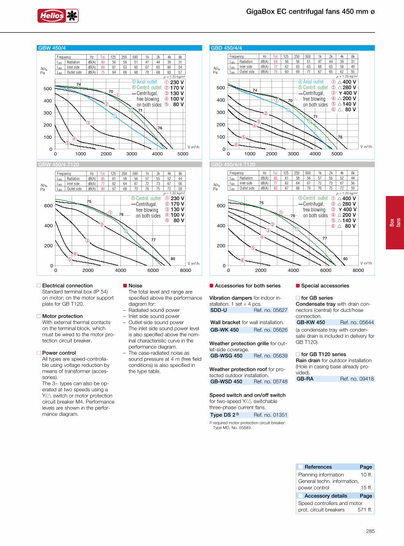
Box
fans
GigaBox EC centrifugal fans 450 mm ø
n Special accessories
n for GB seriesCondensate tray with drain con-nectors (central) for duct/hoseconnection.GB-KW 450 Ref. no. 05644(a condensate tray with conden-sate drain is included in delivery for GB T120).
n for GB T120 seriesRain drain for outdoor installation(Hole in casing base already pro-vided).GB-RA Ref. no. 09418
n Electrical connection Standard terminal box (IP 54) on motor; on the motor support plate for GB T120.
n Motor protection With external thermal contacts on the terminal block, which must be wired to the motor pro-tection circuit breaker.
n Power control All types are speed-controlla-ble using voltage reduction by means of transformer (acces-sories).
The 3~ types can also be op-erated at two speeds using a Y/s switch or motor protection circuit breaker M4. Performance levels are shown in the perfor-mance diagram.
n Noise The total level and range are specified above the performance diagram for:
– Radiated sound power– Inlet side sound power– Outlet side sound power The inlet side sound power level
is also specified above the nom-inal characteristic curve in the performance diagram.
– The case-radiated noise as sound pressure at 4 m (free field conditions) is also specified in the type table.
n Accessories for both series
Vibration dampers for indoor in-stallation. 1 set = 4 pcs.SDD-U Ref. no. 05627 Wall bracket for wall installation.GB-WK 450 Ref. no. 05626
Weather protection grille for out-let-side coverage.GB-WSG 450 Ref. no. 05639
Weather protection roof for pro-tected outdoor installation.GB-WSD 450 Ref. no. 05748
Speed switch and on/off switch for two-speed Y/s switchable three-phase current fans.Type DS 2 2) Ref. no. 01351
2) required motor protection circuit breaker: Type MD, No. 05849.
Frequency Hz Tot. 125 250 500 1k 2k 4k 8k LWA Radiation dB(A) 60 56 56 51 47 44 39 31 LWA Inlet side dB(A) 72 62 63 65 68 63 58 49 LWA Outlet side dB(A) 75 60 69 71 67 65 62 55
V· m3/h
DpfaPa
r = 1.20 kg/m3
é
á
ûô
ê
â
â s 400 Vê s 280 Vô Y 400 V û s 200 V á s 140 V é s 80 V
74
70
71
76
GBD 450/4/4
Axial outlet Centrif. outlet Centrifugal,
free blowing on both sides
R
A
R
A
Frequency Hz Tot. 125 250 500 1k 2k 4k 8k LWA Radiation dB(A) 60 56 56 51 47 44 39 31 LWA Inlet side dB(A) 69 61 63 65 67 65 60 54 LWA Outlet side dB(A) 75 64 66 68 70 68 63 57
áû
ô
ê
â
V· m3/h
DpfaPa
r = 1.20 kg/m3
74
70
71
76
GBW 450/4
â 230 Vê 170 Vô 130 V û 100 V á 80 V
Axial outlet Centrif. outlet Centrifugal,
free blowing on both sides
R
A
R
A
Frequency Hz Tot. 125 250 500 1k 2k 4k 8k LWA Radiation dB(A) 65 61 58 56 57 55 52 44 LWA Inlet side dB(A) 77 62 64 67 72 73 67 56 LWA Outlet side dB(A) 80 67 68 70 76 75 72 59
â 230 Vê 170 Vô 130 V û 100 V á 80 V
áû
ô
ê
â
V· m3/h
DpfaPa
r = 1.20 kg/m3
75
76
77
80
Centrif. outlet Centrifugal,
free blowing on both sides
GBW 450/4 T120
R
R
Frequency Hz Tot. 125 250 500 1k 2k 4k 8k LWA Radiation dB(A) 65 61 58 56 57 55 52 44 LWA Inlet side dB(A) 77 62 64 67 72 73 67 56 LWA Outlet side dB(A) 80 67 68 70 76 75 72 59
V· m3/h
DpfaPa
r = 1.20 kg/m3
é
á
ûô
ê
â
â s 400 Vê s 280 Vô Y 400 V û s 200 V á s 140 V é s 80 V
75
76
77
80
GBD 450/4/4 T120
Centrif. outlet Centrifugal,
free blowing on both sides
R
R
n References Page
Planning information 10 ff.General techn. information,power control 15 ff.
n Accessory details Page
Speed controllers and motorprot. circuit breakers 571 ff.
285
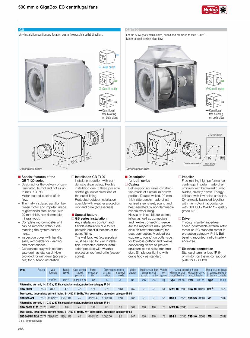
500 mm ø GigaBox EC centrifugal fans
Dimensions in mm Dimensions in mm
n Installation GB T120 Installation position with con-
densate drain below. Flexible installation due to three possible centrifugal outlet directions of the outlet fitting.
Protected outdoor installation possible with weather protection roof and grille (accessories).
n Special featuren GB series installation Any installation position and
flexible installation due to five possible outlet directions of the outlet fitting.
The wall bracket (accessories) must be used for wall installa-tion. Protected outdoor instal-lation possible with weather protection roof and grille (acces-sories).
n Special features of the GB T120 series– Designed for the delivery of con-
taminated, humid and hot air up to max. 120 °C.
– Motor located outside of air flow.
– Thermally insulated partition be- tween motor and impeller, made of galvanised steel sheet, with 20 mm thick, non-flammable mineral wool.– Complete motor-impeller unit
can be removed without dis-mantling the system compo-nents.
– Inspection cover with handle, easily removable for cleaning and maintenance.
– Condensate tray with conden-sate drain as standard. Hole provided for rain drain (accesso-ries) for outdoor installation.
n Description for both seriesn Casing Self-supporting frame construc-
tion made of aluminium hollow profiles. Double-walled, 20 mm thick side panels made of gal-vanised steel sheet, sound and heat insulated by non-flammable mineral wool lining. Nozzle on inlet side for optimal inflow as well as connectors and flexible connecting sleeve (for the respective max. permis-sible air flow temperature) for duct connection. Moulded part (square to round) on outlet side for low-loss outflow and flexible connecting sleeve to prevent structure-borne noise transmis-sion. Simple positioning with crane hook as standard.
n Impeller Free-running high performance
centrifugal impeller made of al-uminium with backward curved blades, directly driven. Energy-
efficient with low noise emission. Dynamically balanced together with the motor in accordance with DIN ISO 21940-11 – quality grade 6.3.
n Drive Through maintenance-free,
speed-controllable external rotor motor or IEC standard motor in protection category IP 54. Ball bearing mounted, radio interfer-ence-free.
n Electrical connection Standard terminal box (IP 54) on motor; on the motor support plate for GB T120.
GB T120
For the delivery of contaminated, humid and hot air up to max. 120 °C. Motor located outside of air flow.
Centrif. outlet
Centrifugal, free blowing on both sides
R
Max. flow rate
Ratedspeed
947 120 110 75 RDS 4 01316 TSD 3.0 01502 MD 05849 GBD 500/4/4 T120 05777 7320/8350 1120/1370 45 1.60/2.50 2.50.95/1.30
301 120 100 75 MWS 10 01946 — — GBW 500/4 T120 05776 8345 1340 45 6.1 7.01.40
50 50 GBD 500/4/4 05518 8000/9200 1075/1340 45 1.60/2.80 2.90 867 570.97/1.45 RDS 7 01578 TSD 5.5 01503 MD 05849
GBW 500/4 05517 8321 1401 47 6.70 9.60 865 65 55 611.50 MWS 10 01946 TSW 10 01498 MW 1) 01579
Speed controller 5-step with motor prot. without mot. prot. circuit breaker circuit breaker
Type Ref. no. Case-radiated sound
pressure
Current consumption at rated in control voltage mode
Wiringdiagram
Maximum air flow temperature at
rat. volt. control
Weight net
approx. .V m3/h min-1 dB(A) at 4 m A A No. +°C +°C kg
Powerconsump-
tion
kW
Mot. prot. circ. break. for connecting built-in thermal contacts
Type Ref. no. Type Ref. no. Type Ref. no.
Two-speed, three-phase current motor, 3~, 400 V, 50 Hz, Y/s connection, protection category IP 54
Alternating current, 1~, 230 V, 50 Hz, capacitor motor, protection category IP 54
Two-speed, three-phase current motor, 3~, 400 V, 50 Hz, Y/s connection, protection category IP 54
Alternating current, 1~, 230 V, 50 Hz, capacitor motor, protection category IP 54
1) Incl. operating switch.
GB
Axial outletA
Centrif. outlet
Centrifugal, free blowing on both sides
R
Any installation position and location due to five possible outlet directions.
View from below
Condensate drain Rain drain
286
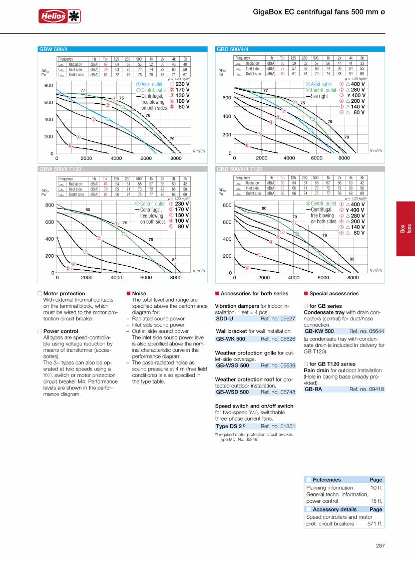
Box
fans
Frequency Hz Tot. 125 250 500 1k 2k 4k 8k LWA Radiation dB(A) 65 54 61 58 57 56 50 42 LWA Inlet side dB(A) 79 65 71 73 72 73 68 58 LWA Outlet side dB(A) 82 66 74 75 77 76 68 60
â 230 Vê 170 Vô 130 V û 100 V á 80 V
áû
ô
ê
â
V· m3/h
DpfaPa
r = 1.20 kg/m3
GBW 500/4 T120
80
79
79
82
Centrif. outlet Centrifugal,
free blowing on both sides
R
R
n Motor protection With external thermal contacts on the terminal block, which must be wired to the motor pro-tection circuit breaker.
n Power control All types are speed-controlla-ble using voltage reduction by means of transformer (acces-sories).
The 3~ types can also be op-erated at two speeds using a Y/s switch or motor protection circuit breaker M4. Performance levels are shown in the perfor-mance diagram.
n Noise The total level and range are specified above the performance diagram for:
– Radiated sound power– Inlet side sound power– Outlet side sound power The inlet side sound power level
is also specified above the nom-inal characteristic curve in the performance diagram.
– The case-radiated noise as sound pressure at 4 m (free field conditions) is also specified in the type table.
n Special accessories
n for GB seriesCondensate tray with drain con-nectors (central) for duct/hoseconnection.GB-KW 500 Ref. no. 05644(a condensate tray with conden-sate drain is included in delivery for GB T120).
n for GB T120 seriesRain drain for outdoor installation(Hole in casing base already pro-vided).GB-RA Ref. no. 09418
GigaBox EC centrifugal fans 500 mm ø
n Accessories for both series
Vibration dampers for indoor in-stallation. 1 set = 4 pcs.SDD-U Ref. no. 05627 Wall bracket for wall installation.GB-WK 500 Ref. no. 05626
Weather protection grille for out-let-side coverage.GB-WSG 500 Ref. no. 05639
Weather protection roof for pro-tected outdoor installation.GB-WSD 500 Ref. no. 05748
Speed switch and on/off switch for two-speed Y/s switchable three-phase current fans.Type DS 2 2) Ref. no. 01351
2) required motor protection circuit breaker: Type MD, No. 05849.
Frequency Hz Tot. 125 250 500 1k 2k 4k 8k LWA Radiation dB(A) 67 64 63 53 52 50 46 40 LWA Inlet side dB(A) 79 63 72 72 74 72 66 59 LWA Outlet side dB(A) 83 72 75 76 78 75 71 67
â 230 Vê 170 Vô 130 V û 100 V á 80 V
á
û
ô
êâ
V· m3/h
DpfaPa
r = 1.20 kg/m3
77
75
76
79
GBW 500/4
R
A
Axial outlet Centrif. outlet Centrifugal,
free blowing on both sides
R
A
Frequency Hz Tot. 125 250 500 1k 2k 4k 8k LWA Radiation dB(A) 65 59 62 57 56 47 41 33 LWA Inlet side dB(A) 77 57 66 69 74 70 64 55 LWA Outlet side dB(A) 80 61 73 74 74 73 69 60
V· m3/h
DpfaPa
r = 1.20 kg/m3
é
á
ûô
ê
â
â s 400 Vê s 280 Vô Y 400 V û s 200 V á s 140 V é s 80 V
77
75
76
79
GBD 500/4/4
Axial outlet Centrif. outlet See right
R
A
R
A
Frequency Hz Tot. 125 250 500 1k 2k 4k 8k LWA Radiation dB(A) 65 54 61 58 57 56 50 42 LWA Inlet side dB(A) 79 65 71 73 72 73 68 58 LWA Outlet side dB(A) 82 66 74 75 77 76 68 60
V· m3/h
DpfaPa
r = 1.20 kg/m3
é
á
ûô
ê
â
â s 400 Vê Y 400 Vô s 280 V û s 200 V á s 140 V é s 80 V
GBD 500/4/4 T120
80
79
79
82
Centrif. outlet Centrifugal,
free blowing on both sides
R
R
n References Page
Planning information 10 ff.General techn. information,power control 15 ff.
n Accessory details Page
Speed controllers and motorprot. circuit breakers 571 ff.
287
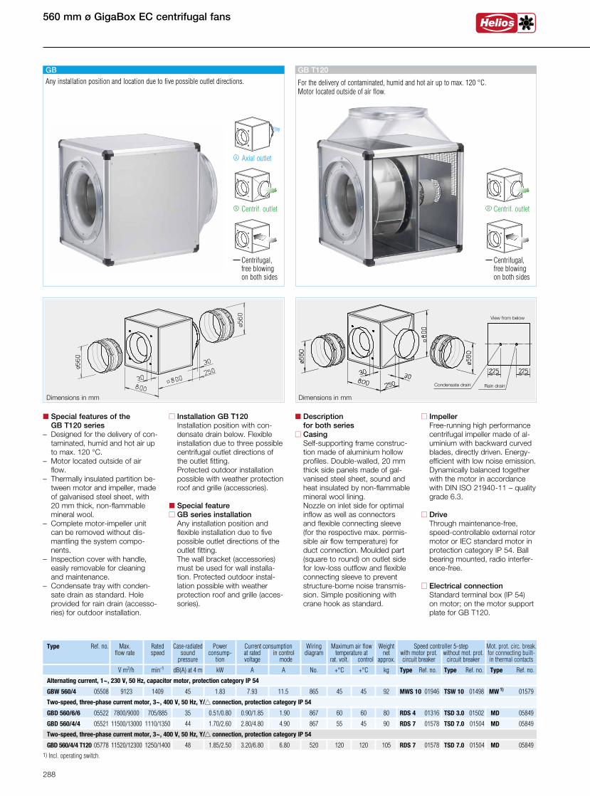
560 mm ø GigaBox EC centrifugal fans
Dimensions in mm Dimensions in mm
n Installation GB T120 Installation position with con-
densate drain below. Flexible installation due to three possible centrifugal outlet directions of the outlet fitting.
Protected outdoor installation possible with weather protection roof and grille (accessories).
n Special featuren GB series installation Any installation position and
flexible installation due to five possible outlet directions of the outlet fitting.
The wall bracket (accessories) must be used for wall installa-tion. Protected outdoor instal-lation possible with weather protection roof and grille (acces-sories).
n Special features of the GB T120 series– Designed for the delivery of con-
taminated, humid and hot air up to max. 120 °C.
– Motor located outside of air flow.
– Thermally insulated partition be- tween motor and impeller, made of galvanised steel sheet, with 20 mm thick, non-flammable mineral wool.– Complete motor-impeller unit
can be removed without dis-mantling the system compo-nents.
– Inspection cover with handle, easily removable for cleaning and maintenance.
– Condensate tray with conden-sate drain as standard. Hole provided for rain drain (accesso-ries) for outdoor installation.
n Description for both seriesn Casing Self-supporting frame construc-
tion made of aluminium hollow profiles. Double-walled, 20 mm thick side panels made of gal-vanised steel sheet, sound and heat insulated by non-flammable mineral wool lining. Nozzle on inlet side for optimal inflow as well as connectors and flexible connecting sleeve (for the respective max. permis-sible air flow temperature) for duct connection. Moulded part (square to round) on outlet side for low-loss outflow and flexible connecting sleeve to prevent structure-borne noise transmis-sion. Simple positioning with crane hook as standard.
n Impeller Free-running high performance
centrifugal impeller made of al-uminium with backward curved blades, directly driven. Energy-
efficient with low noise emission. Dynamically balanced together with the motor in accordance with DIN ISO 21940-11 – quality grade 6.3.
n Drive Through maintenance-free,
speed-controllable external rotor motor or IEC standard motor in protection category IP 54. Ball bearing mounted, radio interfer-ence-free.
n Electrical connection Standard terminal box (IP 54) on motor; on the motor support plate for GB T120.
Centrif. outlet
Centrifugal, free blowing on both sides
R
GB T120
For the delivery of contaminated, humid and hot air up to max. 120 °C. Motor located outside of air flow.
Type Ref. no.
45 45 GBW 560/4 05508 9123 1409 45 7.93 11.5 865 921.83 MWS 10 01946 TSW 10 01498 MW 1) 01579
GBD 560/4/4 T120 05778 11520/12300 1250/1400 48 3.20/6.80 6.80 520 120 120 1051.85/2.50 RDS 7 01578 TSD 7.0 01504 MD 05849
Speed controller 5-step with motor prot. without mot. prot. circuit breaker circuit breaker
Case-radiated sound
pressure
Current consumption at rated in control voltage mode
Wiringdiagram
Maximum air flow temperature at
rat. volt. control
Weight net
approx. .V m3/h min-1 dB(A) at 4 m A A No. +°C +°C kg
Powerconsump-
tion
kW
GBD 560/4/4 05521 11500/13000 1110/1350 44 2.80/4.80 4.90 867 55 45 901.70/2.60 RDS 7 01578 TSD 7.0 01504 MD 05849
Mot. prot. circ. break. for connecting built-in thermal contacts
Type Ref. no. Type Ref. no. Type Ref. no.
60 60 GBD 560/6/6 05522 7800/9000 705/885 35 0.90/1.85 1.90 867 800.51/0.80 RDS 4 01316 TSD 3.0 01502 MD 05849
Max. flow rate
Ratedspeed
Alternating current, 1~, 230 V, 50 Hz, capacitor motor, protection category IP 54
Two-speed, three-phase current motor, 3~, 400 V, 50 Hz, Y/s connection, protection category IP 54
Two-speed, three-phase current motor, 3~, 400 V, 50 Hz, Y/s connection, protection category IP 54
1) Incl. operating switch.
GB
Axial outletA
Centrif. outlet
Centrifugal, free blowing on both sides
R
Any installation position and location due to five possible outlet directions.
View from below
Condensate drain Rain drain
288
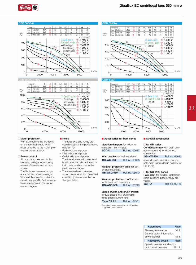
Box
fans
n Motor protection With external thermal contacts on the terminal block, which must be wired to the motor pro-tection circuit breaker.
n Power control All types are speed-controlla-ble using voltage reduction by means of transformer (acces-sories).
The 3~ types can also be op-erated at two speeds using a Y/s switch or motor protection circuit breaker M4. Performance levels are shown in the perfor-mance diagram.
n Noise The total level and range are specified above the performance diagram for:
– Radiated sound power– Inlet side sound power– Outlet side sound power The inlet side sound power level
is also specified above the nom-inal characteristic curve in the performance diagram.
– The case-radiated noise as sound pressure at 4 m (free field conditions) is also specified in the type table.
n Accessories for both series
Vibration dampers for indoor in-stallation. 1 set = 4 pcs.SDD-U Ref. no. 05627 Wall bracket for wall installation.GB-WK 560 Ref. no. 05626
Weather protection grille for out-let-side coverage.GB-WSG 560 Ref. no. 05640
Weather protection roof for pro-tected outdoor installation.GB-WSD 560 Ref. no. 05749
Speed switch and on/off switch for two-speed Y/s switchable three-phase current fans.Type DS 2 2) Ref. no. 01351
2) required motor protection circuit breaker: Type MD, No. 05849.
n Special accessories
n for GB seriesCondensate tray with drain con-nectors (central) for duct/hoseconnection.GB-KW 560 Ref. no. 05645(a condensate tray with conden-sate drain is included in delivery for GB T120).
n for GB T120 seriesRain drain for outdoor installation(Hole in casing base already pro-vided).GB-RA Ref. no. 09418
GigaBox EC centrifugal fans 560 mm ø
Frequency Hz Tot. 125 250 500 1k 2k 4k 8k LWA Radiation dB(A) 65 62 61 51 50 48 44 38 LWA Inlet side dB(A) 76 63 68 69 71 69 64 57 LWA Outlet side dB(A) 82 71 73 76 77 74 70 61
DpfaPa
r = 1.20 kg/m3
á
û
ô
ê
â
â s 400 Vê s 280 Vô Y 400 V û s 200 V á s 140 V
8377
82
GBW 560/4
V· m3/h
Axial outlet Centrif. outlet See left
78
R
A
RA
Frequency Hz Tot. 125 250 500 1k 2k 4k 8k LWA Radiation dB(A) 68 61 62 60 60 60 56 50 LWA Inlet side dB(A) 82 69 78 75 74 73 70 62 LWA Outlet side dB(A) 85 76 77 79 79 77 72 64
V· m3/h
DpfaPa
r = 1.20 kg/m3
é
á
ûô
êâ
â s 400 Vê Y 400 Vô s 280 V û s 200 V á s 140 V é s 80 V
8281
82
85
Centrif. outlet Centrifugal, free blowing on both sides
GBD 560/4/4 T120
R
R
Frequency Hz Tot. 125 250 500 1k 2k 4k 8k LWA Radiation dB(A) 55 52 51 42 40 37 32 25 LWA Inlet side dB(A) 68 51 53 63 64 61 53 43 LWA Outlet side dB(A) 72 60 62 69 67 66 61 50
V· m3/h
DpfaPa
r = 1.20 kg/m3
é
á
ûô
ê
â
70
67
68
72
GBD 560/6/6
â s 400 Vê s 280 Vô Y 400 V û s 200 V á s 140 V é s 80 V
Axial outlet Centrif. outlet Centrifugal,
free blowing on both sides
R
A
A
R
0 4000 8000 120000
200
400
600
800
Frequency Hz Tot. 125 250 500 1k 2k 4k 8k LWA Radiation dB(A) 64 64 64 48 50 46 43 37 LWA Inlet side dB(A) 77 57 66 69 74 70 64 55 LWA Outlet side dB(A) 81 62 74 75 75 74 70 61
Axial outlet Centrif. outlet See left
V· m3/h
DpfaPa
r = 1.20 kg/m3
é
á
ûô
ê
â
â s 400 Vê s 280 Vô Y 400 V û s 200 V á s 140 V é s 80 V
79
76
77
81
GBD 560/4/4
RA
R
A
n References Page
Planning information 10 ff.General techn. information,power control 15 ff.
n Accessory details Page
Speed controllers and motorprot. circuit breakers 571 ff.
289
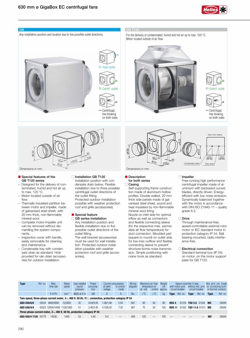
Dimensions in mmDimensions in mm
GB T120
For the delivery of contaminated, humid and hot air up to max. 120 °C. Motor located outside of air flow.
Centrif. outlet
Centrifugal, free blowing on both sides
R
n Installation GB T120 Installation position with con-
densate drain below. Flexible installation due to three possible centrifugal outlet directions of the outlet fitting.
Protected outdoor installation possible with weather protection roof and grille (accessories).
n Special featuren GB series installation Any installation position and
flexible installation due to five possible outlet directions of the outlet fitting.
The wall bracket (accessories) must be used for wall installa-tion. Protected outdoor instal-lation possible with weather protection roof and grille (acces-sories).
n Special features of the GB T120 series– Designed for the delivery of con-
taminated, humid and hot air up to max. 120 °C.
– Motor located outside of air flow.
– Thermally insulated partition be- tween motor and impeller, made of galvanised steel sheet, with 20 mm thick, non-flammable mineral wool.– Complete motor-impeller unit
can be removed without dis-mantling the system compo-nents.
– Inspection cover with handle, easily removable for cleaning and maintenance.
– Condensate tray with conden-sate drain as standard. Hole provided for rain drain (accesso-ries) for outdoor installation.
n Description for both seriesn Casing Self-supporting frame construc-
tion made of aluminium hollow profiles. Double-walled, 20 mm thick side panels made of gal-vanised steel sheet, sound and heat insulated by non-flammable mineral wool lining. Nozzle on inlet side for optimal inflow as well as connectors and flexible connecting sleeve (for the respective max. permis-sible air flow temperature) for duct connection. Moulded part (square to round) on outlet side for low-loss outflow and flexible connecting sleeve to prevent structure-borne noise transmis-sion. Simple positioning with crane hook as standard.
n Impeller Free-running high performance
centrifugal impeller made of al-uminium with backward curved blades, directly driven. Energy-
efficient with low noise emission. Dynamically balanced together with the motor in accordance with DIN ISO 21940-11 – quality grade 6.3.
n Drive Through maintenance-free,
speed-controllable external rotor motor or IEC standard motor in protection category IP 54. Ball bearing mounted, radio interfer-ence-free.
n Electrical connection Standard terminal box (IP 54) on motor; on the motor support plate for GB T120.
630 mm ø GigaBox EC centrifugal fans
GBD 630/4 T120 05779 14200 1445 53 8.0 — 499 120 — 1054.40 — — — — MD 05849
Speed controller 5-step with motor prot. without mot. prot. circuit breaker circuit breaker
Type Ref. no. Case-radiated sound
pressure
Current consumption at rated in control voltage mode
Wiringdiagram
Maximum air flow temperature at
rat. volt. control
Weight net
approx. .V m3/h min-1 dB(A) at 4 m A A No. +°C +°C kg
Powerconsump-
tion
kW
GBD 630/4/4 05523 12954/14430 1128/1383 51 4.10/6.20 7.20 867 75 50 1052.40/3.45 RDS 11 01332 TSD 11.0 01513 MD 05849
Mot. prot. circ. break. for connecting built-in thermal contacts
Type Ref. no. Type Ref. no. Type Ref. no.
60 60 GBD 630/6/6 05524 8600/9990 723/893 42 1.08/1.88 2.03 867 860.64/0.93 RDS 4 01316 TSD 5.5 01503 MD 05849
Max. flow rate
Ratedspeed
Two-speed, three-phase current motor, 3~, 400 V, 50 Hz, Y/s connection, protection category IP 54
Three-phase current motor, 3~, 400 V, 50 Hz, protection category IP 54
GB
Axial outletA
Centrif. outlet
Centrifugal, free blowing on both sides
R
Any installation position and location due to five possible outlet directions.
View from below
Condensate drain Rain drain
290
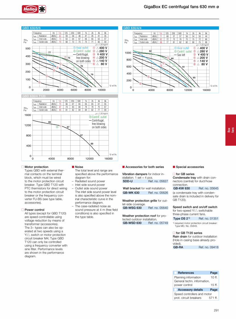
Box
fans
n Motor protection Types GBD with external ther-mal contacts on the terminal block, which must be wired to the motor protection circuit breaker. Type GBD T120 with PTC thermistors for direct wiring to the motor protection circuit breaker or the frequency con-verter FU-BS (see type table, accessories).
n Power control All types (except for GBD T120) are speed-controllable using voltage reduction by means of transformer (accessories).
The 3~ types can also be op-erated at two speeds using a Y/s switch or motor protection circuit breaker M4; Type GBD T120 can only be controlled using a frequency converter with sine filter. Performance levels are shown in the performance diagram.
n Noise The total level and range are specified above the performance diagram for:
– Radiated sound power– Inlet side sound power– Outlet side sound power The inlet side sound power level
is also specified above the nom-inal characteristic curve in the performance diagram.
– The case-radiated noise as sound pressure at 4 m (free field conditions) is also specified in the type table.
n Accessories for both series
Vibration dampers for indoor in-stallation. 1 set = 4 pcs.SDD-U Ref. no. 05627 Wall bracket for wall installation.GB-WK 630 Ref. no. 05626
Weather protection grille for out-let-side coverage.GB-WSG 630 Ref. no. 05640
Weather protection roof for pro-tected outdoor installation.GB-WSD 630 Ref. no. 05749
n Special accessories
n for GB seriesCondensate tray with drain con-nectors (central) for duct/hoseconnection.GB-KW 630 Ref. no. 05645(a condensate tray with conden-sate drain is included in delivery for GB T120).
Speed switch and on/off switch for two-speed Y/s switchable three-phase current fans.Type DS 2 1) Ref. no. 01351
1) required motor protection circuit breaker: Type MD, No. 05849.
n for GB T120 seriesRain drain for outdoor installation(Hole in casing base already pro-vided).GB-RA Ref. no. 09418
GigaBox EC centrifugal fans 630 mm ø
Frequency Hz Tot. 125 250 500 1k 2k 4k 8k LWA Radiation dB(A) 71 68 57 57 56 54 50 44 LWA Inlet side dB(A) 82 72 73 76 75 75 72 66 LWA Outlet side dB(A) 88 77 81 82 82 80 75 68
DpfaPa
á
û
ôê
r = 1.20 kg/m3
â
V· m3/h
82
80
81
85
R
A
GBD 630/4/4
é
â s 400 Vê s 280 Vô Y 400 V û s 200 V á s 140 V é s 80 V
Axial outlet Centrif. outlet See left
R
A
Frequency Hz Tot. 125 250 500 1k 2k 4k 8k LWA Radiation dB(A) 62 59 58 48 47 45 41 35 LWA Inlet side dB(A) 73 63 64 67 66 66 63 57 LWA Outlet side dB(A) 79 68 72 73 73 71 66 59
V· m3/h
DpfaPa
r = 1.20 kg/m3
é
á
ûô
ê
â
â s 400 Vê s 280 Vô Y 400 V û s 200 V á s 140 V é s 80 V
77
75
76
79
GBD 630/6/6
Axial outlet Centrif. outlet Centrifugal, free blowing on both sides
R
A
R
A
n References Page
Planning information 10 ff.General techn. information,power control 15 ff.
n Accessory details Page
Speed controllers and motorprot. circuit breakers 571 ff.
Frequency Hz Tot. 125 250 500 1k 2k 4k 8k LWA Radiation dB(A) 73 66 67 65 65 65 61 55 LWA Inlet side dB(A) 87 74 83 80 79 78 75 67 LWA Outlet side dB(A) 90 81 82 84 84 82 77 69
V· m3/h
DpfaPa
r = 1.20 kg/m3
â
89
87
87
89
GBD 630/4 T120
R
Centrif. outlet Centrifugal, free blowing on both sides
R
291
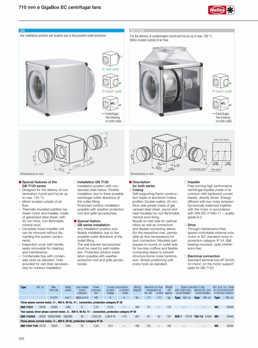
GBD 710/4 T120 05756 18200 1465 55 10.4 — 499 120 — 1885.89 — — MD 05849
710 mm ø GigaBox EC centrifugal fans
Dimensions in mm Dimensions in mm
GB T120
For the delivery of contaminated, humid and hot air up to max. 120 °C. Motor located outside of air flow.
Centrif. outlet
Centrifugal, free blowing on both sides
R
n Installation GB T120 Installation position with con-
densate drain below. Flexible installation due to three possible centrifugal outlet directions of the outlet fitting.
Protected outdoor installation possible with weather protection roof and grille (accessories).
n Special featuren GB series installation Any installation position and
flexible installation due to five possible outlet directions of the outlet fitting.
The wall bracket (accessories) must be used for wall installa-tion. Protected outdoor instal-lation possible with weather protection roof and grille (acces-sories).
n Special features of the GB T120 series– Designed for the delivery of con-
taminated, humid and hot air up to max. 120 °C.
– Motor located outside of air flow.
– Thermally insulated partition be- tween motor and impeller, made of galvanised steel sheet, with 20 mm thick, non-flammable mineral wool.– Complete motor-impeller unit
can be removed without dis-mantling the system compo-nents.
– Inspection cover with handle, easily removable for cleaning and maintenance.
– Condensate tray with conden-sate drain as standard. Hole provided for rain drain (accesso-ries) for outdoor installation.
n Description for both seriesn Casing Self-supporting frame construc-
tion made of aluminium hollow profiles. Double-walled, 20 mm thick side panels made of gal-vanised steel sheet, sound and heat insulated by non-flammable mineral wool lining. Nozzle on inlet side for optimal inflow as well as connectors and flexible connecting sleeve (for the respective max. permis-sible air flow temperature) for duct connection. Moulded part (square to round) on outlet side for low-loss outflow and flexible connecting sleeve to prevent structure-borne noise transmis-sion. Simple positioning with crane hook as standard.
n Impeller Free-running high performance
centrifugal impeller made of al-uminium with backward curved blades, directly driven. Energy-
efficient with low noise emission. Dynamically balanced together with the motor in accordance with DIN ISO 21940-11 – quality grade 6.3.
n Drive Through maintenance-free,
speed-controllable external rotor motor or IEC standard motor in protection category IP 54. Ball bearing mounted, radio interfer-ence-free.
n Electrical connection Standard terminal box (IP 54/55) on motor; on the motor support plate for GB T120.
GBD 710/4 05529 1465 51 10.20 — 499 75 — 1705.97 — — MD 0584920285
Speed controller 5-step with motor prot. without mot. prot. circuit breaker circuit breaker
GBD 710/6/6 05525 690/890 46 2.90/4.70 4.70 867 50 50 157
Type Ref. no. Max. flow rate
Ratedspeed
Case-radiated sound
pressure
Current consumption at rated in control voltage mode
Wiringdiagram
Maximum air flow temperature at
rat. volt. control
Weight net
approx. .V m3/h min-1 dB(A) at 4 m A A No. +°C +°C kg
1.55/2.45
Powerconsump-
tion
kW
RDS 7 01578 TSD 7.0 01504 MD 05849
Mot. prot. circ. break. for connecting built-in thermal contacts
Type Ref. no. Type Ref. no. Type Ref. no.
16500/19000
Two-speed, three-phase current motor, 3~, 400 V, 50 Hz, Y/s connection, protection category IP 54
Three-phase current motor, 3~, 400 V, 50 Hz, Y/s connection, protection category IP 55
Three-phase current motor, 3~, 400 V, 50 Hz, protection category IP 54
GB
Axial outletA
Centrif. outlet
Centrifugal, free blowing on both sides
R
Any installation position and location due to five possible outlet directions.
View from below
Condensate drain Rain drain
292
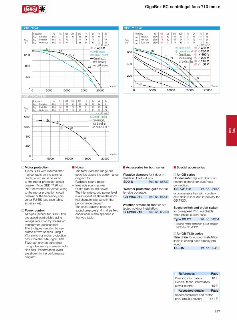
Box
fans
GigaBox EC centrifugal fans 710 mm ø
n Motor protection Types GBD with external ther-mal contacts on the terminal block, which must be wired to the motor protection circuit breaker. Type GBD T120 with PTC thermistors for direct wiring to the motor protection circuit breaker or the frequency con-verter FU-BS (see type table, accessories).
n Power control All types (except for GBD T120) are speed-controllable using voltage reduction by means of transformer (accessories).
The 3~ types can also be op-erated at two speeds using a Y/s switch or motor protection circuit breaker M4; Type GBD T120 can only be controlled using a frequency converter with sine filter. Performance levels are shown in the performance diagram.
n Noise The total level and range are specified above the performance diagram for:
– Radiated sound power– Inlet side sound power– Outlet side sound power The inlet side sound power level
is also specified above the nom-inal characteristic curve in the performance diagram.
– The case-radiated noise as sound pressure at 4 m (free field conditions) is also specified in the type table.
n Accessories for both series
Vibration dampers for indoor in-stallation. 1 set = 4 pcs.SDD-U Ref. no. 05627 Weather protection grille for out-let-side coverage.GB-WSG 710 Ref. no. 05641
Weather protection roof for pro-tected outdoor installation.GB-WSD 710 Ref. no. 05750
n Special accessories
n for GB seriesCondensate tray with drain con-nectors (central) for duct/hoseconnection.GB-KW 710 Ref. no. 05646(a condensate tray with conden-sate drain is included in delivery for GB T120).
Speed switch and on/off switch for two-speed Y/s switchable three-phase current fans.Type DS 2 1) Ref. no. 01351
1) required motor protection circuit breaker: Type MD, No. 05849.
n for GB T120 seriesRain drain for outdoor installation(Hole in casing base already pro-vided).GB-RA Ref. no. 09418
Frequency Hz Tot. 125 250 500 1k 2k 4k 8k LWA Radiation dB(A) 66 63 62 53 51 48 43 36 LWA Inlet side dB(A) 79 62 64 74 75 72 64 54 LWA Outlet side dB(A) 83 71 75 80 78 77 72 61
V· m3/h
DpfaPa
r = 1.20 kg/m3
é
á
ûô
ê
â
80
78
79
82
GBD 710/6/6
â s 400 Vê s 280 Vô Y 400 V û s 200 V á s 140 V é s 80 V
Axial outlet Centrif. outlet Centrifugal, free blowing on both sides
R
A
RA
Frequency Hz Tot. 125 250 500 1k 2k 4k 8k LWA Radiation dB(A) 71 67 68 58 56 53 48 41 LWA Inlet side dB(A) 82 70 73 77 76 74 71 60 LWA Outlet side dB(A) 88 71 73 83 84 81 73 63
V· m3/h
DpfaPa
r = 1.20 kg/m3
â
8482
83
86
GBD 710/4
â s 400 V Axial outlet Centrif. outlet Centrifugal, free blowing on both sides
R
A
R
A
n References Page
Planning information 10 ff.General techn. information,power control 15 ff.
n Accessory details Page
Speed controllers and motorprot. circuit breakers 571 ff.
Frequency Hz Tot. 125 250 500 1k 2k 4k 8k LWA Radiation dB(A) 75 70 67 65 68 65 64 61 LWA Inlet side dB(A) 86 73 76 76 81 81 67 69 LWA Outlet side dB(A) 87 77 78 80 81 82 77 70
V· m3/h
DpfaPa
r = 1.20 kg/m3
â
8987
85
87
GBD 710/4 T120
Centrif. outlet Centrifugal,
free blowing on both sides
R
R
293