gl-01, guidelines for the measurement of radio frequency ...rfsafetysolutions.com/s/canada's...
TRANSCRIPT
GL-01Issue 2
October 2005
Spectrum Management and Telecommunications
Guideline
Guidelines for the Measurement ofRadio Frequency Fields at Frequenciesfrom 3 kHz to 300 GHz
Aussi disponible en français - LD-01

i
Acknowledgement
A joint government/industry committee under the auspices of Industry Canada prepared the presentdocument. A subcommittee under the Broadcasting Technical Advisory Committee (B-TAC) hadpreviously produced part of the work.
Members of the Committee were:
Andrew Lam (Chairperson) Spectrum Engineering BranchIndustry Canada
Dr. Art Thansandote Radiation Protection BureauHealth Canada
Greg Gajda Radiation Protection BureauHealth Canada
Pierre Labarre Pierre Labarre & Associates
Wayne Stacey Canadian Association of Broadcasters
Gerald Bergin Canadian Radio-Television Commission
Suzanne Lamarre Canadian Broadcasting Corporation
Doug Allen D.E.M. Allen & Associates
Allan Leung Ontario Regional OfficeIndustry Canada
Paul Frew Motorola Canada Limited
Mark Kuisma Department of National Defence
Eric Augstman NAV CANADA
Andy McGregor Nortel Networks
Arto Chubukjian Spectrum Engineering BranchIndustry Canada
Rob Cepella Spectrum Management BranchIndustry Canada

ii
Ben Nguyen Ontario Regional OfficeIndustry Canada
Brian Kasper Spectrum Engineering BranchIndustry Canada
Britt Brousseau Interfax
Jack Wojcik Aprel Laboratories
Peter Munzer Bell Mobility
Members of the B-TAC Sub-Committee
Andrew Lam (Chairperson) Broadcasting Regulation BranchIndustry Canada
Jack Dadourian Broadcasting Regulation BranchIndustry Canada
Dr. Art Thansandote Bureau of Radiation & MedicalDevices, Health & Welfare Canada
Dr. Jules Lebel Communications Research Centre
Pierre Labarre Pierre Labarre & Associates
Wayne Stacey Canadian Association of Broadcasters
Suzanne Lamarre Canadian Broadcasting Corporation
John Dexter Broadcasting Regulation BranchIndustry Canada
Paul Vaccani Engineering ProgramsIndustry Canada
Arie Lubienietzky Canadian Radio - Television and TelecommunicationsCommission
Edward Aslan Narda Microwave
Paul Rayment Spectrum Management EngineeringIndustry Canada
Jennifer Horwood Interfax Canada
Hibtullah Khomusi Engineering ProgramsIndustry Canada

iii
Tom Jones Radio Regulatory BranchIndustry Canada
Darius Breau Radio Regulatory BranchIndustry Canada
iv
Table of Contents
Page
1. Introduction . . . . . . . . . . . . . . . . . . . . . . . . . . . . . . . . . . . . . . . . . . . . . . . . . . . . . . . . . . . . . . . . . 11.1 Background . . . . . . . . . . . . . . . . . . . . . . . . . . . . . . . . . . . . . . . . . . . . . . . . . . . . . . . . . . . . 11.2 Scope . . . . . . . . . . . . . . . . . . . . . . . . . . . . . . . . . . . . . . . . . . . . . . . . . . . . . . . . . . . . . . . . . 1
1.2.1 Purpose . . . . . . . . . . . . . . . . . . . . . . . . . . . . . . . . . . . . . . . . . . . . . . . . . . . . . . . . . . 11.2.2 Measurements . . . . . . . . . . . . . . . . . . . . . . . . . . . . . . . . . . . . . . . . . . . . . . . . . . . . 21.2.3 Sources of Emission . . . . . . . . . . . . . . . . . . . . . . . . . . . . . . . . . . . . . . . . . . . . . . . . 2
2. Measurement Parameters . . . . . . . . . . . . . . . . . . . . . . . . . . . . . . . . . . . . . . . . . . . . . . . . . . . . . . 22.1 Frequency Range . . . . . . . . . . . . . . . . . . . . . . . . . . . . . . . . . . . . . . . . . . . . . . . . . . . . . . . . 2
2.1.1 3 kHz to 300 MHz . . . . . . . . . . . . . . . . . . . . . . . . . . . . . . . . . . . . . . . . . . . . . . . . . 22.1.2 300 MHz to 300 GHz . . . . . . . . . . . . . . . . . . . . . . . . . . . . . . . . . . . . . . . . . . . . . . . 2
2.2 Source Parameters . . . . . . . . . . . . . . . . . . . . . . . . . . . . . . . . . . . . . . . . . . . . . . . . . . . . . . . 32.2.1 Modulation . . . . . . . . . . . . . . . . . . . . . . . . . . . . . . . . . . . . . . . . . . . . . . . . . . . . . . . 32.2.2 Near Field and Far Field Regions . . . . . . . . . . . . . . . . . . . . . . . . . . . . . . . . . . . . . 32.2.3 Power Levels and Power Density . . . . . . . . . . . . . . . . . . . . . . . . . . . . . . . . . . . . . 42.2.4 Radiation Pattern . . . . . . . . . . . . . . . . . . . . . . . . . . . . . . . . . . . . . . . . . . . . . . . . . . 62.2.5 Polarization . . . . . . . . . . . . . . . . . . . . . . . . . . . . . . . . . . . . . . . . . . . . . . . . . . . . . . 62.2.6 Single or Complex . . . . . . . . . . . . . . . . . . . . . . . . . . . . . . . . . . . . . . . . . . . . . . . . . 6
2.3 Radiation Leakage . . . . . . . . . . . . . . . . . . . . . . . . . . . . . . . . . . . . . . . . . . . . . . . . . . . . . . . 62.4 Secondary Radiation . . . . . . . . . . . . . . . . . . . . . . . . . . . . . . . . . . . . . . . . . . . . . . . . . . . . . 72.5 Induced and Contact Currents . . . . . . . . . . . . . . . . . . . . . . . . . . . . . . . . . . . . . . . . . . . . . . 72.6 Specific Absorption Rate (SAR) . . . . . . . . . . . . . . . . . . . . . . . . . . . . . . . . . . . . . . . . . . . . 72.7 Measurement Errors . . . . . . . . . . . . . . . . . . . . . . . . . . . . . . . . . . . . . . . . . . . . . . . . . . . . . . 8
3. Instrumentation . . . . . . . . . . . . . . . . . . . . . . . . . . . . . . . . . . . . . . . . . . . . . . . . . . . . . . . . . . . . . . 83.1 Types of Measuring Instruments . . . . . . . . . . . . . . . . . . . . . . . . . . . . . . . . . . . . . . . . . . . . 8
3.1.1 Electric and Magnetic Field Strength Meters . . . . . . . . . . . . . . . . . . . . . . . . . . . . 93.1.2 Spectrum Analyzers . . . . . . . . . . . . . . . . . . . . . . . . . . . . . . . . . . . . . . . . . . . . . . . . 93.1.3 Power Density Meters . . . . . . . . . . . . . . . . . . . . . . . . . . . . . . . . . . . . . . . . . . . . . . 93.1.4 Shaped Frequency Response . . . . . . . . . . . . . . . . . . . . . . . . . . . . . . . . . . . . . . . . 113.1.5 Combined Electric and Magnetic Field Probes . . . . . . . . . . . . . . . . . . . . . . . . . . 123.1.6 Induced Current Meters . . . . . . . . . . . . . . . . . . . . . . . . . . . . . . . . . . . . . . . . . . . . 123.1.7 Contact Current Meters . . . . . . . . . . . . . . . . . . . . . . . . . . . . . . . . . . . . . . . . . . . . 12
3.2 Desirable Performance Characteristics . . . . . . . . . . . . . . . . . . . . . . . . . . . . . . . . . . . . . . 133.2.1 Physical Characteristics . . . . . . . . . . . . . . . . . . . . . . . . . . . . . . . . . . . . . . . . . . . . 133.2.2 Electrical Performance Characteristics . . . . . . . . . . . . . . . . . . . . . . . . . . . . . . . . 14
3.3 Calibration . . . . . . . . . . . . . . . . . . . . . . . . . . . . . . . . . . . . . . . . . . . . . . . . . . . . . . . . . . . . 163.3.1 Methods . . . . . . . . . . . . . . . . . . . . . . . . . . . . . . . . . . . . . . . . . . . . . . . . . . . . . . . . 173.3.2 Evaluation of Survey Instruments . . . . . . . . . . . . . . . . . . . . . . . . . . . . . . . . . . . . 193.3.3 Practical Measurement Accuracy . . . . . . . . . . . . . . . . . . . . . . . . . . . . . . . . . . . . 19
v
4. Measurement . . . . . . . . . . . . . . . . . . . . . . . . . . . . . . . . . . . . . . . . . . . . . . . . . . . . . . . . . . . . . . . 204.1 Preliminary Considerations . . . . . . . . . . . . . . . . . . . . . . . . . . . . . . . . . . . . . . . . . . . . . . . 204.2 Procedures . . . . . . . . . . . . . . . . . . . . . . . . . . . . . . . . . . . . . . . . . . . . . . . . . . . . . . . . . . . . 24
4.2.1 General Considerations . . . . . . . . . . . . . . . . . . . . . . . . . . . . . . . . . . . . . . . . . . . . 244.2.2 Far Field Measurements: Single Source . . . . . . . . . . . . . . . . . . . . . . . . . . . . . . . 274.2.3 Far Field Measurements: Complex Source . . . . . . . . . . . . . . . . . . . . . . . . . . . . . 284.2.4 Near Field Measurements . . . . . . . . . . . . . . . . . . . . . . . . . . . . . . . . . . . . . . . . . . 284.2.5 Specific Absorption Rate (SAR) Measurement . . . . . . . . . . . . . . . . . . . . . . . . . . 284.2.6 Induced Current and Contact Current Measurement . . . . . . . . . . . . . . . . . . . . . . 29
References . . . . . . . . . . . . . . . . . . . . . . . . . . . . . . . . . . . . . . . . . . . . . . . . . . . . . . . . . . . . . . . . . . . . . . . . 30
Appendix 1 . . . . . . . . . . . . . . . . . . . . . . . . . . . . . . . . . . . . . . . . . . . . . . . . . . . . . . . . . . . . . . . . . . . . . . . 31Section A - Procedures for Measuring the Levels of RF Energy at and in the Vicinity of
FM/Digital Radio, VHF/UHF/Digital TV and MDS Transmitting Sites . . . . . . . . . . . . 31Section B - Procedures for Measuring the Levels of
RF Energy at and in the Vicinity of AM Radio Transmitting Sites . . . . . . . . . . . . . . . . 34
Appendix 2 - Measurement Procedure for Microwave Installations . . . . . . . . . . . . . . . . . . . . . . . . 38
Appendix 3 . . . . . . . . . . . . . . . . . . . . . . . . . . . . . . . . . . . . . . . . . . . . . . . . . . . . . . . . . . . . . . . . . . . . . . . 48Section A - Procedures for Measuring the Levels of RF
Energy Associated With Land Mobile, Cellular and PCS Services . . . . . . . . . . . . . . . . 48Section B - Procedures for Measuring the Levels of RF Energy Associated with the
Portable and Mobile Units of Land Mobile, Cellular and PCS Services . . . . . . . . . . . . . 54
Appendix 4 - Measurement Procedures for Radar Installations . . . . . . . . . . . . . . . . . . . . . . . . . . . 55
Appendix 5 - Guidelines for Measurement Uncertainties . . . . . . . . . . . . . . . . . . . . . . . . . . . . . . . . . 62
Guidelines for the Measurement of Radio Frequency Fields at Frequencies from 3 kHz to 300 GHz GL-01
1 Safety Code 6 can be found on Health Canada's Web site at:http://www.hc-sc.gc.ca/ewh-semt/pubs/radiation/99ehd-dhm237/index_e.html.
1
1. Introduction
1.1 Background
The use and application of electrical devices has steadily increased over the past decades resulting in acorresponding increase in electromagnetic (EM) fields (also termed non-ionizing radiation) in theenvironment. Public concern over the exposure to these fields has prompted many scientists andresearchers to investigate possible effects and risks to human health.
Throughout the world, considerable research effort has been devoted to determine the effects ofnon-ionizing radiation exposure on human and public authorities responded to this concern by issuingexposure limits and safety guidelines for exposure to radio frequency fields.
Health Canada has issued a document entitled Limits of Human Exposure to RadiofrequencyElectromagnetic Fields in the Frequency Range from 3 kHz to 300 GHz - Safety Code 6 (SC6) whichoutlines recommended limits of exposure to radio frequency electromagnetic (RF) fields from 3 kHz -300 GHz.1 In conjunction with this guideline, Industry Canada requires an assessment of non-ionizingradiation as part of the environmental review process for all telecommunication service licenceapplications. In order to assist the applicants on the subject, the Department has developed softwareprograms to predict levels of RF energy near transmitter sites. However, field measurement may still berequired in certain cases to evaluate the actual levels of radio frequency fields.
1.2 Scope
1.2.1 Purpose
This document outlines some principles and background information for the measurement of radiofrequency electromagnetic fields. It also provides a number of recommended measurement proceduresfor the different types of telecommunication service. The techniques for both the near field and far fieldmeasurements are based on the instrumentation that is currently available. The recommendedprocedures are not considered to be appropriate for the measurement of electromagnetic fields in thereactive near field region.
The document is to be used by people who work in the RF discipline and with the assumption that theuser has a basic knowledge of electromagnetic field theory and practice.
The recommended procedures do not extend to measurements in the very low frequency band (below1 kHz).
Guidelines for the Measurement of Radio Frequency Fields at Frequencies from 3 kHz to 300 GHz GL-01
2
1.2.2 Measurements
The procedures presented in this document may be used for the following:
1. Measurement of radiating EM fields;
2. Measurement of leakage and re-radiated EM fields;
3. Measurement of induced EM fields in the body.
1.2.3 Sources of Emission
Sources of emission in the present context refer to the different types of radio frequency transmittersemployed in the different telecommunication services. These transmitters may exhibit very differentspectral, spatial and temporal characteristics due to the nature and the requirements of each type ofservice. The recommended procedures take into consideration the normal features and the circumstancesof each type of service and the characteristics of the transmitters and radiation patterns.
2. Measurement Parameters
2.1 Frequency Range
2.1.1 3 kHz to 300 MHz
Services in this frequency range include maritime navigational communications, areonauticalradionavigation and radiocommunication, analog AM radio broadcasting, shortwave broadcasting, landmobile communication and fixed services, VHF radio (FM) and television broadcasting and amateurradio communication.
Measurement procedures and techniques over this frequency range vary according to the frequency andthe type of service. In general, for services below 300 MHz, measurements of both the electric (E) fieldsand the magnetic (H) fields may be required. In addition, in cases of some high-power transmissions(e.g. AM radio service) measurements of induced current and contact current may also be required.
2.1.2 300 MHz to 300 GHz
Services in this frequency range include UHF television and digital radio broadcasting, fixed,landmobile/PCS and satellite systems. Over this frequency range, the wavelengths of theelectromagnetic fields and the dimensions of the antenna are relatively short, measurement locations areusually situated in the far field region, and in general, only electric (E) field measurements are required.In the far field region, the magnetic (H) field and the electric (E) field are related by a constant. In thiscase, measuring only the | E |² component can approximate the power density.
Guidelines for the Measurement of Radio Frequency Fields at Frequencies from 3 kHz to 300 GHz GL-01
3
R =λπ2
(2.1)
Ra
=2 2
λ(2.2)
2.2 Source Parameters
Radio frequency electromagnetic sources radiate energy into space through antennas installed on towersand buildings. These sources have widely different characteristics and thus require proper selection ofinstrumentation in hazard determination. Below are the pertinent characteristics of these sources.
2.2.1 Modulation
Transmitted electromagnetic waves may have various forms. The most fundamental form is acontinuous wave (CW) or un-modulated carrier in which the wave oscillates at a single frequency. Suchcarriers may be modulated by another signal or message. When a CW wave is modulated by pulsing, orby varying its amplitude, frequency or phase, the wave is called a pulse, an amplitude, a frequency, or aphase-modulated wave, respectively.
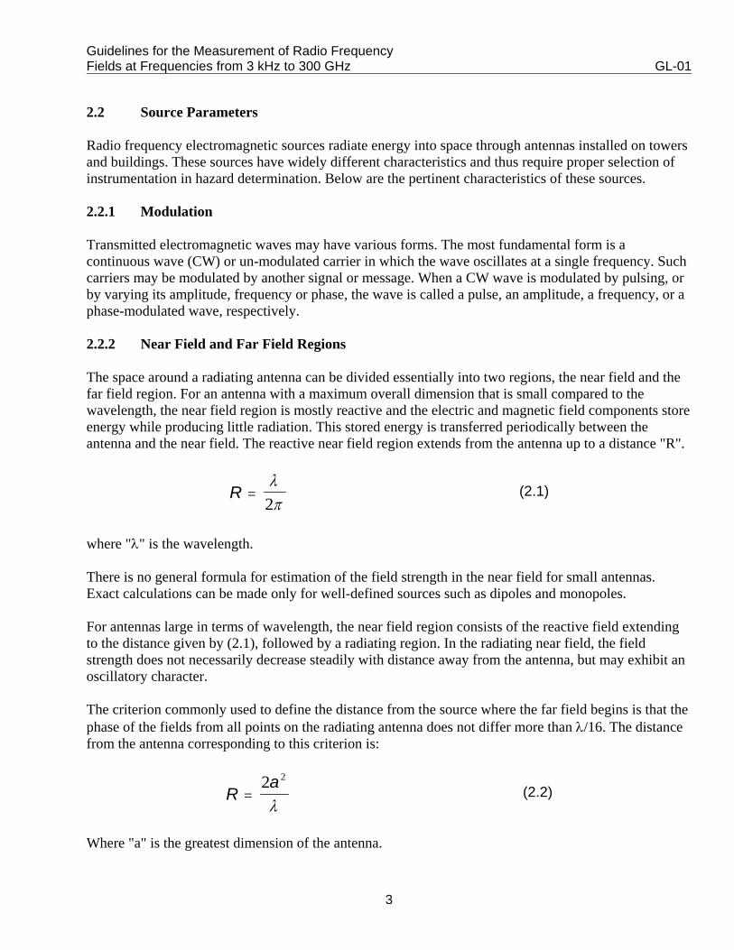
2.2.2 Near Field and Far Field Regions
The space around a radiating antenna can be divided essentially into two regions, the near field and thefar field region. For an antenna with a maximum overall dimension that is small compared to thewavelength, the near field region is mostly reactive and the electric and magnetic field components storeenergy while producing little radiation. This stored energy is transferred periodically between theantenna and the near field. The reactive near field region extends from the antenna up to a distance "R".
where "λ" is the wavelength.
There is no general formula for estimation of the field strength in the near field for small antennas.Exact calculations can be made only for well-defined sources such as dipoles and monopoles.
For antennas large in terms of wavelength, the near field region consists of the reactive field extendingto the distance given by (2.1), followed by a radiating region. In the radiating near field, the fieldstrength does not necessarily decrease steadily with distance away from the antenna, but may exhibit anoscillatory character.
The criterion commonly used to define the distance from the source where the far field begins is that thephase of the fields from all points on the radiating antenna does not differ more than λ/16. The distancefrom the antenna corresponding to this criterion is:
Where "a" is the greatest dimension of the antenna.
Guidelines for the Measurement of Radio Frequency Fields at Frequencies from 3 kHz to 300 GHz GL-01
4
Ra
= 052
.λ
(2.3)
EH
= η (2.4)
SE
H= =2
2
ηη (2.5)
EH
= =η 377Ω (2.6)
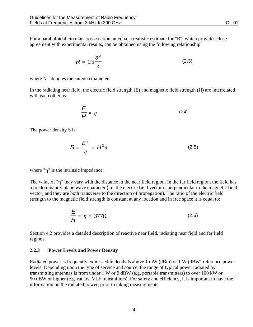
For a paraboloidal circular-cross-section antenna, a realistic estimate for "R", which provides closeagreement with experimental results, can be obtained using the following relationship:
where "a" denotes the antenna diameter.
In the radiating near field, the electric field strength (E) and magnetic field strength (H) are interrelatedwith each other as:
The power density S is:
where "η" is the intrinsic impedance.
The value of "η" may vary with the distance in the near field region. In the far field region, the field hasa predominantly plane wave character (i.e. the electric field vector is perpendicular to the magnetic fieldvector, and they are both transverse to the direction of propagation). The ratio of the electric fieldstrength to the magnetic field strength is constant at any location and in free space it is equal to:
Section 4.2 provides a detailed description of reactive near field, radiating near field and far fieldregions.
2.2.3 Power Levels and Power Density
Radiated power is frequently expressed in decibels above 1 mW (dBm) or 1 W (dBW) reference powerlevels. Depending upon the type of service and source, the range of typical power radiated bytransmitting antennas is from under 1 W or 0 dBW (e.g. portable transmitters) to over 100 kW or50 dBW or higher (e.g. radars, VLF transmitters). For safety and efficiency, it is important to have theinformation on the radiated power, prior to taking measurements.
Guidelines for the Measurement of Radio Frequency Fields at Frequencies from 3 kHz to 300 GHz GL-01
5
SPA
a= 4 (2.7)
SP G
ra=
4 2π(2.8)
GAe=
42
πλ
(2.9)
EP
re=
30(2.10)
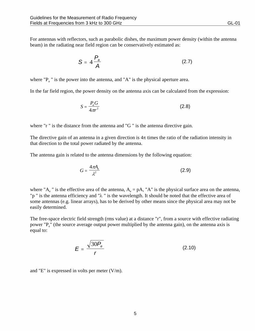
For antennas with reflectors, such as parabolic dishes, the maximum power density (within the antennabeam) in the radiating near field region can be conservatively estimated as:
where "Pa " is the power into the antenna, and "A" is the physical aperture area.
In the far field region, the power density on the antenna axis can be calculated from the expression:
where "r " is the distance from the antenna and "G " is the antenna directive gain.
The directive gain of an antenna in a given direction is 4π times the ratio of the radiation intensity inthat direction to the total power radiated by the antenna.
The antenna gain is related to the antenna dimensions by the following equation:
where "Ae " is the effective area of the antenna, Ae = pA, "A" is the physical surface area on the antenna,"p " is the antenna efficiency and "λ " is the wavelength. It should be noted that the effective area ofsome antennas (e.g. linear arrays), has to be derived by other means since the physical area may not beeasily determined.
The free-space electric field strength (rms value) at a distance "r", from a source with effective radiatingpower "Pe" (the source average output power multiplied by the antenna gain), on the antenna axis isequal to:
and "E" is expressed in volts per meter (V/m).
Guidelines for the Measurement of Radio Frequency Fields at Frequencies from 3 kHz to 300 GHz GL-01
6
2.2.4 Radiation Pattern
Electromagnetic waves are radiated into space by means of antennas. The radiation pattern of anantenna determines the spatial distribution of the radiated energy. A pattern taken in the planecontaining the electric field vector is referred to as an E-plane pattern. A pattern taken in a planeperpendicular to an E-plane is called an H-plane pattern. The directional pattern of an antenna describeshow much it concentrates energy in one direction in preference to radiation in other directions.
In the near field, the radiation pattern of an antenna changes with distance from the source, whereas inthe far field no significant change with distance occurs.
2.2.5 Polarization
The orientation of an electric field vector in the plane orthogonal to the direction of propagation is calledpolarization. If the electric field vector is always oriented in a given direction, the wave is linearlypolarized. If the electric field vector rotates around the direction of propagation, maintaining a constantmagnitude, the wave is circularly polarized. If the extremity of the electric field vector traces an ellipse,the wave is elliptically polarized. The rotation of the electric field vector occurs in one of two directions,either clockwise or counter-clockwise.
It is difficult to predict the orientation of the electric field in the near field region, as the transmittingantenna cannot be considered as a point source in this region. In the far field region, the antennabecomes a point source, the electric and magnetic components of the field become orthogonal to thedirection of propagation and their polarization characteristics do not vary with distance.
2.2.6 Single or Complex
At a measurement survey site, there may be only a single source or several sources of electromagneticfields. A single source may have strong harmonic content that can produce electromagnetic fields atmultiple frequencies. In addition, several types of RF sources such as AM, FM, TV, land-mobile andfixed transmitters may commonly be installed on an antenna farm or multiple-use tower and canproduce a complex electromagnetic environment. In these situations, it is difficult to estimate themaximum expected field levels. Both broadband and narrowband instrumentation should be employedto fully characterize the electromagnetic environment.
2.3 Radiation Leakage
At many transmitting sites, there may be unexpected radiation leakage emanating from electronicequipment (e.g. power amplifiers), a crack in the shielding cabinet or conduit, a joint betweentransmission cables or sections of waveguide. These leakages can result in localized hot spots with theelectromagnetic fields in excess of the exposure limits. The nature of the leakage fields is similar to thatof the near field around an antenna. Therefore, any type of polarizations may exist in the vicinity of theleak location. There is no reliable method to predict the extent of the leakage radiation, or the type of thefield produced (reactive or radiating). In general, the location of the leak is not known and may only bedetected by trial and error. Although many types of instruments are available for field measurements,those that have isotropic characteristics are generally better suited to probe radiation leakage.
Guidelines for the Measurement of Radio Frequency Fields at Frequencies from 3 kHz to 300 GHz GL-01
7
2.4 Secondary Radiation
RF electromagnetic energy from an active radiator induces electric charges or currents on ungroundedor poorly grounded conducting objects such as metal flag poles, sign posts, window frames, fences andwalls of metallic buildings. The amount of the induced current depends on the physical characteristics ofthe object (size, shape, orientation with respect to the source) and the frequency of the incident field.This current produces its own electric and magnetic fields in close proximity to the object. The producedfields, which are generally reactive, interact with the incident field and may result in so-called "hotspots" or the enhanced E and/or H fields close to the object surface. Since the conducting objects act assecondary radiators when exposed to ambient RF fields, they are sometimes referred to as passive orparasitic re-radiators. The enhanced fields generally diminish to the ambient levels in the surroundingareas within very short distances of the secondary source. Field strength reduction is generallyexponential with highest strengths on the surface of the re-radiating object. The enhanced fields arehighly non-uniform in their spatial distribution on the re-radiating object and are generally difficult topredict by theoretical methods. Hot spots are best evaluated by measurements.
2.5 Induced and Contact Currents
An RF field induces an alternating electric potential on ungrounded or poorly grounded conductingobjects. When a person touches such objects, RF current flows through the person's body to the ground.This type of current is known as contact current. Even though a person may not be touching a metallicobject, RF current that is induced in the body by RF fields may also flow through the body to theground. This type of current is referred to as induced body current. Modest levels of these RF currentsmay cause perception, while higher values may result in shock or burns. The 1999 version of SafetyCode 6 includes recommended limits for both contact and induced currents in the frequency range from3 kHz to 110 MHz, with the intention to reduce the potential for shock or burns. Under certain exposureconditions, the contact and induced currents shall be evaluated as they may exceed the limits, eventhough the field strength limits are not exceeded. These conditions may occur when the electric fieldstrength is as low as 20-25% of the exposure limit.
2.6 Specific Absorption Rate (SAR)
Specific absorption rate (SAR) is the rate of RF energy absorption per unit mass in the body. SAR hasunits of joules per second per kilogram or watts per kilogram (W/kg). This parameter is used as aprimary indicator of RF energy absorbed in the body when quantifying the biological effects and thusdefining the basic exposure limits. At frequencies between 100 kHz and 10 GHz, SAR limits takeprecedence over field strength and power density limits and shall not be exceeded. When carrying outcompliance evaluation, the SAR should be determined for cases where exposures take place at adistance of 0.2 metres or less from the source. For conditions where SAR determination is impractical,field strength or power density measurement shall be carried out.

Guidelines for the Measurement of Radio Frequency Fields at Frequencies from 3 kHz to 300 GHz GL-01
8
2.7 Measurement Errors
The following factors affect the measurement accuracy of radio frequency electromagnetic fields:
1. If the probe is very close to an active radiator, coupling may occur between the probe's antennas andthe radiator.
2. The ground as well as nearby objects such as a metallic wall can cause partial or total reflection orscattering of the incident waves. These reflections or scattering combine with the energy receiveddirectly from the source, and create interference patterns or multipath effects that may enhance orreduce the field strength at the measurement location.
3. Fields may have several frequencies because of multiple sources of emission or a single source withstrong harmonic content or both.
4. Certain types of modulation may affect the reliability of measured results.
5. Spurious responses of the probes may be a factor, for example, the H field probe may be sensitive toelectric fields, and vice versa.
6. Temperature and humidity may affect the accuracy of the measuring probe. Be sure that these arewithin the working range of the probe. Under very low and high temperature and humidityconditions, correction factors would have to be applied to the measurement data.
7. Errors may result from uncalibrated or mis-calibrated measuring instruments.
3. Instrumentation
3.1 Types of Measuring Instruments
A typical RF field or power density measurement device is composed of a probe, leads and meteringinstrumentation. The probe is used to detect the field. It can either be a conventional antenna or anothertype of sensor. The performance and the application of the measuring instrument as a whole depend to alarge extent on the design and characteristics of the probe. The detected signal is carried by the leads tothe metering instrumentation. To reduce the coupling of the leads with the surrounding field in order tominimize any disturbance, the leads take the form of high resistance wires. The meteringinstrumentation is primarily designed to process and display received field density.
The RF measurement device may be either broadband or narrowband. A broadband device respondsuniformly over a wide frequency range and requires no tuning. A narrowband device may also operateover a wide frequency range, but the reception bandwidth is narrow, and the device must be tuned to thefrequency of interest. Narrowband and wideband devices have their own advantages and disadvantagesdepending on the spectral environment and the type of measurements that are projected.
Guidelines for the Measurement of Radio Frequency Fields at Frequencies from 3 kHz to 300 GHz GL-01
9
3.1.1 Electric and Magnetic Field Strength Meters
Electric and magnetic field strength meters are narrowband devices. They consist of an antenna, cable(s)to carry the signal from the antenna, and a signal conditioning/readout instrument. Field strength metersmay use linear antennas, such as monopoles, dipoles, loops, biconical or conical log spiral antennas,horns or parabolic reflectors. The appropriate field parameters can be determined from a measurementof voltage or power at the selected frequency and at the antenna terminal. The electric (or magnetic)field strength can be derived from information on the antenna gain or antenna factor and the loss in theconnecting cable.
3.1.2 Spectrum Analyzers
Spectrum analyzers are essentially broadband tunable receivers whose reception bandwidth may be setover a wide range of frequencies. They are used to measure the power at the antenna terminal at theselected frequency(ies). If used in combination with a narrowband selective antenna, the overall devicebecomes in concept similar to a field strength meter. However, spectrum analyzers can also beconnected to relatively short antennas to produce a broad response over a given frequency range. In thiscase, the analyzer will display the spectrum of ambient signals and thus will permit to ascertain thefrequencies involved and their relative contribution to the overall power density.
3.1.3 Power Density Meters
Power density meters are generally isotropic and broadband devices. However, there are conceptualdifferences among these devices in the way the fields are detected and processed. The instrumentsdescribed in the following sections have essentially the same basic components (i.e. a probe, aconnecting cable and a conditioning display unit). They are limited to those types which are currentlyavailable and which can provide reasonable accuracy in both near field and far field situations.
Measurements conducted with a power density meter may produce erroneous readings when theconnecting cables are inadvertently aligned with the electric field. This is due to the fact that highresistance leads carrying the signal act as a more efficient antenna at low frequencies (such as in AMbroadcasting band) than the short dipoles in the probe.
3.1.3.1 Diode Rectifiers
Multiple diodes and antenna elements (short dipoles or loops) are arranged in a suitable configuration tosum all three spatial field components independently of polarization and direction of incidence. Threeelements, in an orthogonal arrangement, is required for an isotropic instrument which can be used in anyorientation with respect to the field. Dipoles respond to the electric field, loops to the magnetic field. Toachieve a uniform response over the desired frequency range, the size of the dipole or the loop must besmall compared to the wavelength of the highest frequency to be measured.
Schottky diodes, in general, exhibit some photovoltaic effect. Beamlead hybrid types exhibit this effectto a much greater extent and may produce erroneous readings when illuminated by sunlight or strongincandescent light. Therefore, optically opaque shielding is required to eliminate this effect.
Guidelines for the Measurement of Radio Frequency Fields at Frequencies from 3 kHz to 300 GHz GL-01
10
Diode instruments are non-linear with respect to field strength. At low levels, the rectified voltage isproportional to the square of E (or H). At higher levels, the rectified voltage becomes directlyproportional to E (or H). This change in characteristic requires that the range of operation of the diodebe restricted to low levels to provide a true indication of ⏐E⏐² or⏐H⏐². When the diodes are operated athigher levels, it is required that the output voltages of the individual elements be modified (generallysquared) prior to their summation. When diode instruments are used in pulsed fields they usually changefrom an average to a peak detecting device, hence, measurement errors may be large in fields of highpeak to average ratio.
When adapted to broadband operation, the upper frequency range of a diode- based instrument iscurrently above 12 GHz. The low-frequency limit is below 400 kHz. The burnout characteristics can bein the hundreds of mW/cm2 range.
Diode detectors, depending on design, may be temperature sensitive. Variations in output with ambienttemperature will typically be less than 0.05 dB per "C. Diode units also may be modulation sensitive ifthe square-law region is exceeded, resulting in errors dependent upon the type of modulation.
3.1.3.2 Active Antenna
It is difficult to make accurate, broadband E and H field probes that cover the long wavelength (1000 m)region, using the conventional means described above. In order to provide a flat frequency response andadequate sensitivity in a dipole probe, the load impedance of the detector and the high impedance leadin combination must be greater than the antenna (source) impedance. One solution is to provide a highimpedance RF buffer amplifier that is connected directly to a monopole or loop antenna and which actsas the load. This is practical for frequencies between 10 kHz and several hundred MHz. Commerciallyavailable magnetic and electric field probes, using active electronics, operate at frequencies as low as60 Hz.
A second problem associated with probes without active electronics is that of isolating the signalcarrying leads from the antenna/detector combination. This problem may become severe below about100 MHz, and particularly below 10 MHz. This is due to the fact that the typical high resistance signalcarrying leads serve as a low-pass filter, and their ability to separate the low frequency detected signalfrom the RF field being measured becomes more difficult as the two frequencies approach each other.This results in excessive sensitivity and poor antenna patterns in passive probes.
Finally, at frequencies above about 300 MHz, where "free-space" or uniform irradiation conditionsexist, both the sensor and the metal enclosure of the survey instrument can be exposed to similar levelsof RF, and scattering from the enclosure to the sensor (probe) can cause significant errors.
Active electronic probes eliminate the use of such leads entirely by including the visual display(readout) with the metal box containing the active electronics. A fibre optic data link can be providedfor a remote readout.
Guidelines for the Measurement of Radio Frequency Fields at Frequencies from 3 kHz to 300 GHz GL-01
11
3.1.3.3 Displacement-Current Sensors
In addition to short dipoles and monopoles, a form of parallel plate capacitor, called a displacement-current sensor can be used to measure electric fields normal to its surface or normal to any largeconducting surface. Instruments designed primarily for measuring fields associated with video displayterminals, are based on the displacement-current sensor concept.
Displacement-current sensors are typically used at frequencies in the LF and VLF regions (e.g. from DCto a few hundred kHz) but may effectively be used at frequencies as high as a few hundred MHz.
3.1.3.4 Electro-Optical (Photonic) Sensors
This type of electromagnetic field sensor utilizes a non-metallic, passive sensing element (electro-opticmodulator) with a very broadband response (DC to 20 GHz) that converts electromagnetic field strengthinformation to instantaneous modulation of a laser beam. The laser energy is transmitted via fibre opticsto the modulator.
The modulator impresses amplitude modulation on the laser beam, in proportion to the instantaneousamplitude of the RF electromagnetic field to which the modulator is exposed. The amplitude-modulatedlaser beam is then carried from the modulator to a photodetector that converts the modulated opticalbeam to an electrical signal that represents the instantaneous amplitude of the RF field strength. Thissignal is then detected and processed before being sent to for display.
The above system has been used with electrically small dipoles as an electric field sensor as well as withno antenna (where the electro-optic modulator itself serves as the E field sensor). In addition,conventional antennas can be connected to a commercially available electro-optic modulator via a shortlead, to provide a non-metallic, passive RF link to the antenna.
3.1.3.5 Thermocouples
The detection elements are thin-film type thermocouples. Parts of the film perform the functions of theantenna element. Some low frequency probes also use loop antennas terminated with thermocoupledetectors. The DC output of the thermocouple is proportional to the square of the electric field strength.The major limitation of the thermocouple type radiation monitors is the burnout characteristic. Theburnout characteristic is typically 3 times full scale in terms of average values. Newer designs ofthermocouple instruments have burnout ratings of 15 to 20 times full scale. Thin resistive films providevery broad bandwidth.
3.1.4 Shaped Frequency Response
Safety limits for field strength and power density in Canada are frequency dependent. Probe designs,which rely on dipole-diode elements separately or in conjunction with thermocouple elements, may bedesigned to have a "sensitivity versus frequency" characteristic that is the inverse of the standard. Thisallows the summation and weighing of multiple frequency signals in conformity with the frequencydependent safety limits. The readout of such devices is in % of the standard. The probes may be tailoredto a specific American National Standards Institute (ANSI) or Canadian Standard.
Guidelines for the Measurement of Radio Frequency Fields at Frequencies from 3 kHz to 300 GHz GL-01
12
Shaped frequency response probes may cover only a portion of the frequency range of the standard.Additional probes may be used to complement each other and provide a wider measurement range.When complementary probes are used, these should exhibit good rejection of out-of-band signals.
3.1.5 Combined Electric and Magnetic Field Probes
Devices described in Sections 3.1.3.1 to 3.1.3.5 employ separate probes to measure the electric andmagnetic field components. In the near field region of an RF source, the relative values of the electricand magnetic fields vary considerably with respect to one another, depending on the distance from thesource.
Also, in typical situations, fields may vary rapidly with time. To measure both electric and magneticfield strengths, which vary over time and space, one must place an electric field probe and then amagnetic field probe at exactly the same point. However a measurement uncertainty results, since thefield under study may change during the finite time that elapses between the successive measurements.
A broadband isotropic probe system to measure the electric and magnetic fields simultaneously can beproduced with a set of three mutually orthogonal dipole elements and a set of three mutually orthogonalloops that are physically located within a very small (compared with the shortest wavelength) volume.These elements are described in Section 3.1.3.1. Since the lengths of the dipoles, or the diameter of theloops, are kept small for uniform frequency response, the electric field pickup will be negligible. Thus,the mutual coupling between any of the probe elements is minimized by the use of electrically smallantennas. Detectors based on the use of square law operated diodes or thermocouple are used to providea signal to the electronic circuits to perform summing, data processing or conversion.
3.1.6 Induced Current Meters
Induced current meters display the amount of current induced through the body to ground when anindividual is standing in an electric field created by a high-power transmitter. These currents canprovide an indication of energy absorbed by the body.
Induced current meters are generally stand-on devices that measure the induced current flowing throughthe subject's feet to ground. The stand-on baseplate is made of two stainless steel plates and is, in fact acapacitor/resistor network. The meter reads the current flowing through the resistor connected betweenthe capacitor plates. The size of the baseplate is kept small to minimize any pick-up of electric fieldfrom the sides of the baseplate.
There are also the clamp-on induced current meters that can measure directly the induced current inarms and legs using clamp-on sensors. Typical frequency range of commercial meters is from 10 kHz to100 MHz.
3.1.7 Contact Current Meters
Contact current meters display the amount of current through the body caused by contact with a 'hot'metallic object located in the vicinity of a high-power transmitter.
Guidelines for the Measurement of Radio Frequency Fields at Frequencies from 3 kHz to 300 GHz GL-01
13
Contact current meters generally feature an insulated contact probe for contact with the 'hot' object.Together with a stainless steel baseplate and internal circuitries, the measured current simulates theequivalent induced current by a barefoot individual gripping the 'hot' metallic object. Typical frequencyrange of this type of meter is from 3 kHz to 30 MHz.
3.2 Desirable Performance Characteristics
There are certain characteristics, which are desirable in a survey instrument. They can be arranged intwo classes: physical characteristics and electrical performance characteristics.
3.2.1 Physical Characteristics
3.2.1.1 Portability
The instrument should be lightweight and small to permit convenient operation under restrictiveconditions. The weight should be kept as low as is practical in keeping with good engineering practice.The volume should be convenient for hand held operation.
3.2.1.2 Durability
The display and other components of the device should be durable and able to withstand shock andvibration associated with transportation and handling under difficult conditions. A storage case shouldbe provided.
3.2.1.3 Effects of Temperature, Humidity and Pressure
The accuracy of the device should be specified in terms of effects of temperature, humidity andatmospheric pressure. The extent of the effect of these parameters should be taken into account.
3.2.1.4 Display
The markings should be large enough to be easily read at arm's length. For shaped frequency responseprobes with an the analog type readout, the applicable safety standard should appear within the centralone-third of the full scale reading of the dial. If more than one range of sensitivity is provided, thefull-scale value of the selected range should be indicated. In any case, the analog or digital readoutshould provide a clear indication of the units being displayed.
3.2.1.5 Adjustments
The device should have a minimum number of controls. The functions associated with the controlsshould be clearly labelled and the operating procedures relatively simple.
3.2.1.6 Simplicity
Complicated operating procedures should be avoided. The information provided in the instructionmanual should be sufficient to make accurate measurements.
Guidelines for the Measurement of Radio Frequency Fields at Frequencies from 3 kHz to 300 GHz GL-01
14
3.2.2 Electrical Performance Characteristics
3.2.2.1 Power Supply
The instrument should be battery operated. The battery should be easily replaceable or rechargeable. Atest switch or some other means should be provided to indicate their condition. The instrument shouldbe capable of operating within its rated accuracy for at least eight hours before replacement orrecharging of the batteries becomes necessary.
3.2.2.2 Polarization Factor
Probe antennas based on multiple dipoles or loops will respond to all polarization components of theelectromagnetic field. A device based on a single antenna may respond to the same field by physicalrotation of the single antenna about its axis.
3.2.2.3 Display Units
The instrument should indicate one or more of the following parameters:
(1) average "equivalent plane-wave" power density in milliwatts per square centimetre (mW/cm²)
(2) mean-squared electric field strength in volts squared per metre squared (V2/m2);
(3) mean-squared magnetic field strength in amperes squared per metre squared (A2/m2)
Some instruments display "equivalent plane-wave" power density as derived from the field quantities(E field and H field) being measured.
Instruments with a shaped-frequency response should indicate in terms of "percent of exposure limit"based on the appropriate safety standard.
3.2.2.4 Frequency Range
The manufacturer should specify the frequency range of the device. The dynamic range for flatfrequency response probes should be at least 10 dB below the lowest value and 5 dB above the highestvalue of the safety standard. These limits should also apply to shaped-frequency response instruments.
3.2.2.5 Coupling and Response to Other Radiations
The probe should only respond to the field component being measured (i.e. a dipole antenna shouldrespond to the electric field and should not interact with the magnetic field and vice versa).
The specified accuracy of the instrument should take into account effects such as ionizing radiation,artificial light, sunlight, etc.
Guidelines for the Measurement of Radio Frequency Fields at Frequencies from 3 kHz to 300 GHz GL-01
15
3.2.2.6 Shielding
The housing of the instrument and antenna cables should be designed to reduce or eliminateelectromagnetic interference. The shielding should be effective under conditions in which the maximumcoupling or "pickup" occurs for the unintentional receiving elements.
3.2.2.7 Out-of-Band Response
The manufacturer should specify the out-of-band response characteristics of the instrument to assist theuser in selecting an instrument for a particular application.
3.2.2.8 Modulation
The device should indicate RMS value of the electromagnetic fields. However, the device may also beequipped with a switch for CW and amplitude-modulated continuous wave (AM-CW) modes. Thedevice should also be able to average the narrowest pulse-modulated envelope of a non-continuous wavefield that is expected to be encountered by the surveyor.
3.2.2.9 Static Electricity
Static charges are often induced on the probe of the survey instrument. The device should not indicatefalse levels due to a response to static charges. Windy or dry conditions may also influence the readingof the survey instrument.
3.2.2.10 Recorder Output
It may be desirable to equip the instrument with a recorder output. This will enable the measurement ofhazardous fields without endangering the operator. It will also facilitate spatial and time averaging.
3.2.2.11 Response Time
The response time is generally defined as the time required for the instrument to reach 90% of its finalvalue when exposed to step function CW RF energy. The user should be made aware of the responsetime of the instrument.
3.2.2.12 Special Features
The following is a list of options that can be provided with the instrument:
(1) A "peak-hold" circuit. This is useful when the amplitude of the field is changing during themeasurement;
(2) An alarm or test switch to indicate that the preset level has been exceeded. Also a means should beprovided to alert the user that the measured signal is overloading the instrument;
Guidelines for the Measurement of Radio Frequency Fields at Frequencies from 3 kHz to 300 GHz GL-01
16
(3) A data-logging function, which can provide an average, maximum and minimum values of the fieldcomponents being measured. This function could provide a real-time average of the measured fieldswith an averaging time specified by the user (e.g. six minutes).
3.2.2.13 Stability
The instrument should be able to operate continuously for 10 to 30 minutes without the need to reset thedevice. Automatic electronic reset circuitry can be used to avoid the necessary shielding of the sensitiveprobe from ambient RF fields during the reset process. This is a desirable feature, particularly whenperforming RF surveys in situations where broadcasting or other major communication towers areinvolved. In such environments, RF-free locations may not be available. The instrument should not besensitive to thermal variations within the range of normally encountered temperature extremes. Themanufacturer should specify the maximum zero drift for each range.
3.2.2.14 Measurement Uncertainties
The accuracy of the measured field strength levels can be affected by the uncertainties of the actualmeasurement and the uncertainties of the instrument used to perform the measurement (see Ref. [13] ).Actual measurement uncertainties can be minimized by following proper measurement procedures andinstrumentation uncertainties can be reduced by correct calibration and careful selection of theinstrument. To reduce instrumentation uncertainties, additional procedures may be taken(e.g. conducting single frequency measurements). To increase the confidence level of compliance to thesafety standards, the sample size of measurement points (locations) of a site may be increased toprovide a better indication of field strength values at the site. In any case, the survey report shouldinclude the specifications of the instrument as provided by the manufacturer. The instrumentspecifications should also address the instrument's ability to respond to amplitude-modulated (AM)fields such as pulsed radar signals as well as a multiplicity of signals, which might simultaneouslyilluminate the probe. The instrument readout should permit resolution of the measured field strength towithin at least 5% of the full-scale value. Appendix 5 provides further information on the issue ofmeasurement uncertainties.
3.3 Calibration
To ensure the safety of personnel, compliance with safety guidelines and to provide a basis forcomparing the results of RF hazard, it is recommended that calibration be performed on instrumentsused for measuring various RF fields.
Existing calibration methods are based on the premise that a known field strength can be establishedthrough measurements, calculation, or a combination of both. The device to be calibrated is placed inthis standard field and the meter indication is compared with the known field value. There are threebasic approaches for producing a standard calibrating field: the free-space standard field method,guided-wave method and the TEM Cell method. The selection of technique is dictated by the nature ofthe probe under investigation, the frequency range, the accuracy required and the available hardware forcalibration.
Guidelines for the Measurement of Radio Frequency Fields at Frequencies from 3 kHz to 300 GHz GL-01
17
3.3.1 Methods
3.3.1.1 Free-space Standard Field Method
The objective is to establish a reliable and known calibration field by the free-space method. In mostexperimental setups, a microwave transmitter is employed to generate the reference field. The powerdensity at a point is related to the power delivered to the transmitting antenna, the effective gain of theantenna on the on-axis distance of that point from the antenna.
It is to be noted that this arrangement is valid only when the device being calibrated is sufficiently smalland far enough away from the transmitting antenna so that the amount of energy reflected back into thetransmitting system is insignificant.
It is recommended that calibration should only be performed by qualified personnel in a laboratoryfurnished with proper equipment, and for field measurements, the calibration of the measuringinstruments should be verified at the site using a portable TEM cell.
The main sources of error in the free-space method are multi-path interference from components that arepart of the experimental setup and uncertainties in the antenna gain determination. Errors may be also becaused by misalignment of the transmitter antenna axis to the measuring probe.
3.3.1.2 Rectangular Waveguides
Rectangular waveguides will provide sufficiently uniform fields to be considered for calibrationpurpose. These fields are also predictable. The probe to be calibrated is inserted into the waveguidethrough a hole in the sidewall and positioned in the centre of the guide where the field is nearly uniform.The access hole is kept as small as possible to minimize its effect on the field distribution. Theequivalent power density at the centre of the waveguide can be determined in terms of the square of theelectric field.
When compared to the free-space standard field calibration method, the rectangular waveguide takesconsiderably less space and requires little electromagnetic power. The disadvantage is that themaximum transverse dimension of the waveguide must be less than the wavelength at the highestcalibration frequency to avoid higher order modes that result in complicated field distributions. Hence,this method is generally useful only for frequencies below 2.6 GHz.
3.3.1.3 Calibration using TEM Cells
The transverse electromagnetic cell, commonly known as TEM cell is another guided wave method forcalibrating electromagnetic field probes. The basic TEM cell is a section of two-conductor transmissionline operating in the transverse electromagnetic mode, hence the name. The main body consists of arectangular outer conductor and a flat central conductor located midway between the top and bottomwalls. The dimensions and the tapered ends of the TEM cell are chosen to provide a standard 50 Ωcharacteristic impedance along the entire length of the cell. In the centre of the calibration zone, halfwaybetween the centre conductor and the top or bottom wall of the cell, the electric field is verticallypolarized and uniform. The wave impedance (E/H) will be close to the free-space value of 377 Ω.
Guidelines for the Measurement of Radio Frequency Fields at Frequencies from 3 kHz to 300 GHz GL-01
18
TEM cells may be made in various sizes to accommodate particular needs and frequency ranges.However, since the width must be less than a half-wavelength to avoid higher order modes in the cell,the useful upper frequency of a TEM cell is approximately 500 MHz. There are several factors that needto be considered in more detail when designing or using a TEM cell, IEEE Standard (C95.3) entitled"Recommended Practice for the Measurement of Potentially Hazardous Electromagnetic Fields, RF andMicrowave" provides valuable and detailed information on electrical characteristics, standing waves,size of the probe to be calibrated with respect to plate separation, etc.
3.3.1.4 Magnetic Field Generators
At low frequencies the axial magnetic field (in A/m) at the centre of a circular loop wire is simply thecurrent (in amperes) divided by the loop diameter (in meters). For a single-turn coil in free space, a loopbecomes self-resonant when the circumference approaches the free-space wavelength. For multi-turncoils, the resonant frequency is lower because of capacitance between the turns. Using a coil with a totalwire length less than λ/10, the input impedance is very low but the field strength value can easily becalculated. This type of coil is useful for probe calibration purposes up to about 30 MHz.
There is also another coil arrangement named Helmholz. It consists of two flat coils on the same axis,both carrying current in the same direction. This type of coil system generates a more uniform magneticfield over a larger volume than the single coil. Helmholtz coils are useful up to about 10 MHz. Thisfrequency limit is dictated by the dimensions of the coil which must be small compared with thewavelength.
3.3.1.5 Standard Probe Method
This method is the simplest, and may be the best method of calibrating hazard meters for general fielduse. The object is to have a stable and reliable probe that has been calibrated accurately (by one of thepreviously discussed techniques) for use as a "transfer standard." The standard probe is used to measurethe field strength produced by an arbitrary RF field-generating device (e.g. antenna or TEM cell) over aparticular region in space (or in a waveguide system). Then an uncalibrated probe is placed at the samelocation in the field that the standard probe occupied, and the uncalibrated probe's meter reading iscompared with the known, measured value of the field, based on data obtained with the standard probe.The transmitter and field-generating device used during this process must generate a field that has thedesired magnitude and which is constant with time and the field should be uniform over the regionwhere the unknown probe is placed. Accuracies of about ± 2 to 3 dB are readily attainable with thismethod. The advantages of this approach are convenience, reliability, and simplicity. A potential sourceof error when using the transfer standard to calibrate another probe is the difference in the receivingpatterns of the two probes. Also, in the near field of a radiator, the size of the probe's sensor isimportant. Ideally, the standard and unknown probes should be nominally identical and the calibrationshould be conducted in a field relatively free of spatial variations due to multipath interactions betweenthe probe, the radiator, the anechoic chamber and other field generating components. In TEM cells orparallel plate transmission systems, capacitive coupling between the probe and the centre plate and thewalls of the cell can create calibration errors. The transfer standard probe should be stable, rugged, andnot easily burned out; it should have a large dynamic range, cover a broad frequency range, and possessan isotropic response.
Guidelines for the Measurement of Radio Frequency Fields at Frequencies from 3 kHz to 300 GHz GL-01
19
3.3.2 Evaluation of Survey Instruments
Survey instruments have to be evaluated to determine the uncertainties or errors that may occur whenthe instrument is used to make field measurements. This evaluation also permits the development ofprocedures that can minimize errors in measurements. The following is a list of parameters that shouldbe investigated:
(1) Absolute Calibration. Should be performed at field levels that produce indications that equal orexceed the mid-scale readout of the instrument.
(2) Linearity of the Instrument. In order to establish the linearity of the instrument, measurementsshould be made at field levels that produce indications of 25, 50, 75 and 100% of full scale, oneach range of the readout device.
(3) Frequency Response. The frequency response of the instrument over the band of interest shouldbe established. The response should be relatively flat over the specified frequency range (± 1 to3 dB).
(4) Out-of-band Response. The sensitivity of the instrument as a whole should be evaluated for fieldsat frequencies outside the specified frequency range of the instrument.
(5) Near Field Response. The magnetic field response of an electric field instrument and vice versashould be evaluated.
(6) Polarization. Any variation of the readout as the probe is rotated about the axis of the handleshould be noted.
(7) Lead Pickup. Variations in response as the probe handle is rotated through the E plane or anyextraneous pickup should be noted and quantified.
(8) Temperature Response. Changes in the response of the instrument to a given field over thetemperature range of interest should be determined.
(9) Supply Voltage Response. For battery operated RF survey meters, the overall accuracy of theinstrument should be tested for deviations from the nominal voltage rating of one or more of thebatteries.
(10) Drift and Noise. Short and long term stability of the instrument should be determined with respectto full scale on each measurement range of the instrument, in the absence of electromagnetic fields.
3.3.3 Practical Measurement Accuracy
Several methods for calibrating meters have been discussed and the uncertainties associated with eachmethod were estimated. It is important to understand that one cannot expect to achieve the sameaccuracy when using the meters for practical measurement applications. Some of the reasons are asfollows:
Guidelines for the Measurement of Radio Frequency Fields at Frequencies from 3 kHz to 300 GHz GL-01
20
(1) Meters are usually calibrated in nominally plane wave or uniform fields. Such fields are not alwaysencountered in practice, and the sensor may not respond in the same way to non-planar fields (fieldswith large spatial gradients).
(2) With most calibration methods, only the sensor (probe) is exposed to the field while, in practice, thecomplete system, including the indicating unit and connecting cable, is immersed in the field. Errorscan also result from spurious responses from other parts of the instrument including readout meter(case) and cable. The overall uncertainty added by the above factors is difficult to assess and willvary with the type of meter and usage situation. However, if good measurement procedures arefollowed, accuracies of ± 1 to 3 dB can be expected in practice, with greater uncertainties in nearfield situations and at higher frequencies (shorter wavelengths), or in areas where large reflectingobjects are present.
4. Measurement
4.1 Preliminary Considerations
Before carrying out a survey of potentially hazardous EM fields, it is important to determine as many ofthe known characteristics of the sources of these fields as possible. This will permit a better evaluationof the expected field strength and, consequently, a more appropriate selection of test instruments andtest procedures.
A checklist of source characteristics should include:
(1) type of RF generator and the output power;
(2) carrier frequency(ies);
(3) modulation characteristics (e.g. peak and average values, waveform, signal duty factor, pulse width,pulse-repetition frequency, etc.);
(4) intermittency (e.g. scanning beams, operational duty factors).
(5) number of sources. If more than one source is present, are some or all of the signals coherent? Areintensities likely to add linearly or will they create interference patterns (standing waves etc.); and
(6) spurious frequencies including radiated harmonics.
A checklist of field characteristics may include:
(1) distance of source to test site;
(2) type of antenna and properties including gain, beam-width, elevation and azimuth patterns,orientation, physical size with respect to the distance of the area being surveyed (i.e. near field, etc.);
Guidelines for the Measurement of Radio Frequency Fields at Frequencies from 3 kHz to 300 GHz GL-01
21
(3) polarization; and
(4) existence of absorbing or scattering objects likely to influence the field distribution at the test site.
A review of such a checklist is a necessity if the surveyor is to avoid some simple, but often surprisingsituations. For example, it is necessary to know the location of the source and RF propagation pathduring surveys with hand held probes. Only then can an appropriate assessment of the effect of thepresence of the surveyor's body be made, and measurement errors avoided. Another example commonin leakage situations is the possibility that the levels of the EM fields may be hazardous to the surveyorand may produce malfunction in the instrument electronics if it was not designed for operation in thepresence of such fields.
Evaluation of Expected Field Strength
If the fields are far fields or radiating near fields of an antenna, then the material on theoreticalcalculations of exposure fields in Section 4.2 can be used to obtain field strength estimates. Generalreferences on antennas and hazard surveys are useful.
Field enhancement due to ground reflections could increase by as much as a factor of four times andeven more if focusing effects are present. On the other hand, it should be recognized that such fieldsmeasured in the absence of a person may be misleading relative to hazards. For example, a personexposed in front of a reflecting plane reduces the magnitude of the standing wave.
In the case of low frequencies or small aperture antennas, the existence of potentially hazardous reactivenear fields becomes relevant. Since these fields cannot be calculated with accuracy, measurements of Eand H are usually required. However, one can always utilize the general property (see Ref. [8]) thatreactive fields predominate at distances d close to sources where 2Bd/8<<1. Reactive near fieldamplitudes diminish as 1/d2 or faster, whereas radiation far field amplitudes diminish as 1/d. Generaltexts can sometimes be used to estimate E and H field values at these lower frequencies, and specificliterature on the propagation characteristics of various broadcasting and communication antennas can beused to estimate either near or far fields from these sources.
Determination of Type of Instrument Required
Although many instruments designed for the measurement of electromagnetic fields are broadband innature, none of them cover the entire frequency range of interest and all parameters of potential interest.Some general considerations in the selection of an instrument include the following:
(1) Frequency. Frequencies must be determined in advance so that proper instruments andmeasurement methods can be selected. The presence of several frequencies dictates the use of abroadband device with true RMS response.
(2) Response Time. It is usually desirable to begin a survey using an instrument with a response time(integrator time-constant) of one second or less (the "fast" setting on some commercial instruments).This enables a coarse measurement or the detection of pulse-modulated or intermittent fields (e.g.those created by a scanning radar beam). A "peak hold" feature on some survey instruments can

Guidelines for the Measurement of Radio Frequency Fields at Frequencies from 3 kHz to 300 GHz GL-01
22
provide an accurate indication of moderately fast bursts of RF energy (duration greater than severalmilliseconds). Once a high field strength zone is located, a slower time constant (3 seconds or more)should be used to obtain the time averaged value of the field strength. If the hazard meter stillindicates that an intermittent field exists, other means of recording and averaging should be used.Data logging systems are available specifically for use with RF hazard meters.
(3) Peak Field Limitations. Knowledge of the peak field limitations of the instrument is necessary toprotect probes from damage in some low-duty-factor pulsed fields, such as those associated withradars.
(4) Polarization. Knowledge of the polarization of the fields enables a surveyor to use a non-isotropicprobe for hazard surveys. In the absence of such knowledge, an isotropic probe is highly desirableboth for ensuring accuracy and ease of performance of the survey in a reasonable period of time.
(5) Dynamic Range. The maximum anticipated field strengths should be estimated before measuringemissions from an RF source. A survey instrument capable of withstanding continuous exposure tofield strengths (E2 or H2) of at least ten times the predetermined value should be chosen in order toavoid destruction of the probe sensing elements or the high resistance leads connected to thoseelements. In addition, adequate sensitivity is required to ensure a reasonable signal-to-noise ratiowhen the minimum expected field strengths are being measured.
(6) Near Field Measurement Capabilities. If a leakage situation exists or if the fields in closeproximity to a source are to be measured, care must be taken to select a suitable instrument.
If possible, one should estimate the maximum expected field levels in order to facilitate the selection ofan appropriate survey instrument. In many cases it may be best to begin by using a broadbandinstrument capable of accurately measuring the total field from all sources, including reflections. If thetotal field does not exceed the relevant exposure guideline in accessible areas, and if the measurementtechnique employed is sufficiently accurate, this would mean compliance with that particular guideline,and further measurements would be unnecessary.
When using a broadband survey instrument an average exposure level may be determined by slowlymoving the probe in first a horizontal and then a vertical direction. An average can be estimated byobserving the meter reading during this scanning process. A maximum field reading is also desirable,and, if the instrument has a "peak hold" feature, this can be obtained by observing the peak readingaccording to the instrument instructions. Otherwise, the maximum reading can be determined by simplyrecording the peak during the scanning process.
The term "hot spots" has been used to describe locations where peak readings occur because of localfield distortions or other perturbations in the field and such readings are often found near conductiveobjects.
In many situations there may be several RF sources. For example, a broadcast antenna farm ormultiple-use tower could have several types of RF sources including AM, FM, and TV, as well as land-mobile and microwave transmitters. In such a situation it is generally useful to use both broadband andnarrowband instrumentation to fully characterize the electromagnetic environment.
Guidelines for the Measurement of Radio Frequency Fields at Frequencies from 3 kHz to 300 GHz GL-01
23
Broadband instrumentation could be used to determine what the overall field levels appeared to be,while narrowband instrumentation would be required to determine the relative contributions of eachsignal to the total field.
At frequencies above 300 MHz it is usually sufficient to measure only the electric field (E), or the meansquared electric field, in the far field. However, at lower frequencies both the electric (E) and magneticfield (H) shall be measured.
In many situations a relatively large sampling of data will be necessary to spatially resolve areas of fieldintensification that may be caused by reflection and multipath interference. Areas that are normally areaccessible to the general public should be examined in detail to determine exposure potential.
If narrowband instrumentation and a linear antenna are used, field intensities at three mutuallyorthogonal orientations of the antenna must be obtained at each measurement point. The values of E2 orH2, will then be equal to the sum of the squares of the corresponding orthogonal field components.
If an aperture antenna is used, it should be rotated in both azimuth and elevation until a maximum isobtained. The antenna should then be rotated about its longitudinal axis and the measurement repeatedso that both horizontally and vertically polarized field components are measured.
When making measurements, procedures should be followed which minimize possible sources of error.For example, when the polarization of a field is known, all cables associated with the survey instrumentshould be held perpendicular to the electric field in order to minimize pickup. Ideally, non-conductivecable (e.g. optical fibre) should be used, since substantial error can be introduced by cable pick-up.
Interaction of the entire instrument (probe plus readout device) with the field can be a significantproblem below approximately 10 MHz, and it may be desirable to use a self-contained meter formeasuring electric field at these frequencies. Also, at frequencies below about 1 MHz, the body of theperson making the measurement may become part of the antenna, and error from probe/cable pickupand instrument/body interaction may be reduced by supporting the probe and electronics on a dielectricstructure made of wood, styrofoam, etc. In this connection, it is also desirable to remove all unnecessarypersonnel from an area where a survey is being conducted in order to minimize errors due to reflectionand field perturbation.
In areas with relatively high fields, or pulsed fields with high peak powers, it is a good idea tooccasionally hold the probe fixed and rotate the readout device and move the connecting cable whileobserving the meter reading. Any significant change usually indicates pickup in the leads andinterference problems. When a field strength meter or spectrum analyzer is used in the aboveenvironments, the antenna cable should occasionally be removed and replaced with an impedance-matched termination. Any reading on the device indicates pickup or interference.
Substantial errors may be introduced due to zero drift. If a device is being used which requires zeroing,it should frequently be checked for drift. This should be done with the probe shielded with metal foil,with the source(s) shut off, or with the probe removed from the field.
Guidelines for the Measurement of Radio Frequency Fields at Frequencies from 3 kHz to 300 GHz GL-01
24
4.2 Procedures
4.2.1 General Considerations
Prior to making measurements one should estimate the expected field strength and determine the type ofinstrument required, as discussed in Section 4.1. Some additional approaches and equations forcalculating field strength in various situations are given below. The measurement procedures to be usedmay differ, depending on the source and propagation information available.
Technical Considerations of RF Source Characteristics
Although the prediction of power density levels in the vicinity of RF sources is complicated by manyfactors, useful estimates can be made. The quality of such calculations will depend on the analyticalapproach used as well as on the accuracy of the values of the peak power, pulse duration, pulserepetition rate, antenna radiation patterns, antenna placement, and scanning rates that are used intheoretical computations. Corrections for near field effects may also be appropriate. The operatingparameters listed below must be specified adequately so that the true average radiated power from theantenna, and resulting power density at a distant point can be calculated.
For all sources (pulsed or CW) the antenna type and size, gain, antenna pattern including E and H planebeam widths and sidelobe distribution, antenna height above ground, operating frequency, antenna beamorientation (all possible cases) and the attenuation of the transmission line that connects the RFgenerator to the antenna must be known or estimated. For the calculation of the expected power densitylevels of pulse-modulated sources, the maximum possible values of peak power, pulse duration, andpulse repetition rate which closely approximate, but do not exceed the maximum rated duty factor of atransmitter should be used. In the case of multiple sources, the contribution of each source must beconsidered when estimating the combined effect.
Antennas - On Axis
The space around an antenna can be sub-divided into three zones:
(1) Reactive Near Field Zone. This is the volume of space immediately surrounding the antenna orleakage source where the reactive (non-radiating) components predominate and energy is stored inthe field. The reactive near field extends to a distance of approximately one wavelength from theantenna, except for the case of electrically large antennas (whose physical size is greater, in anydimension, than several wavelengths).
(2) Radiating Near Field Zone (Fresnel Zone). In this zone, which starts at a distance from theantenna where the reactive field has diminished to an insignificant amount, the antenna gain and theangular distribution of the radiated field vary proportionally with distance from the antenna. This isbecause the phase and amplitude relationships of the various waves arriving at the observation pointfrom different areas of the antenna change with distance. For reflector type antennas, such asparabolic dishes, the radiation is somewhat more complex in its distribution pattern.
Guidelines for the Measurement of Radio Frequency Fields at Frequencies from 3 kHz to 300 GHz GL-01
25
rGPW
=π
(4.1)
(3) Far field Zone (Fraunhofer Zone). This is sufficiently far from the source that the phase andamplitude relationships of the waves arriving from different areas of the antenna do not changeappreciably with distance. The antenna gain and angular pattern are essentially independent ofdistance, and the power density is inversely proportional to the square of the distance from thesource. Although the transition from the non-radiating near field is a gradual one, the far field regionis commonly assumed to begin at a distance of about 2a2/λ for antennas with equiphase excitationand extends to infinity ("a" being the largest linear aperture dimension and "λ" the wavelength at thefrequency of interest).
This criterion is not adequate for all types of antennas and should not be applied indiscriminately.
To compute an approximate value for the maximum power density "W" in the Fresnel and far fieldregions of an antenna, use the equation (2.8) of Section 2.2.3.
For commonly used horn and reflector antennas, the maximum power density Wm expected in theradiating near field can be estimated by equation (2.7) of Section 2.2.3.
The values predicted by Eq. (2.7) will be within ± 3 dB of the correct value (in the absence ofreflections) for square apertures with uniform, cosine, and cosine square amplitude tapers, and forcircular apertures with tapers ranging from uniform up to (1-q2)3 (see Ref. [9]). (The taper oraperture field distribution of circular apertures can be represented by the function (1-q2)p, whereq=r/a, in which "a" is the outside radius of the circular aperture and "r" is a radius within theaperture. When the exponent "p" increases, the field distribution becomes more highly tapered (i.e. itbecomes more concentrated at the aperture centre). When p decreases and approaches zero, theaperture field distribution approaches uniform illumination.)
If a computation indicates that the approximate power density is substantially less than the exposurelimit recommended in Safety Code 6, then there is usually no need for further calculation sinceEq. (2.7) provides the maximum power density that can exist on the axis of the beam of an antennathat is focused at infinity, in the absence of reflections. (An antenna focused at a lesser distancecould produce a higher power density in the region of its focal point, but this condition is unusual.)
If the computation from Eq. (2.7) reveals a power density value that is equal to or greater than therecommended exposure limit, then it must be assumed that this value may exist at any point in theradiating near field region and attention should be directed to the exposure fields in the far fieldregions.
Equations (2.7) and (2.8) do not include the effect of ground reflections. Values of power densitythat exceed the free-space value by a factor of four times can result when the main beam is directedtoward a planar ground or reflecting surface. If the shape of the reflecting surface is such that itproduces focusing effects, even greater values may result. After considering the sources of errorcited above one may calculate the distance to the boundary of the potentially hazardous zone (in thepresence of reflections) as follows:
Guidelines for the Measurement of Radio Frequency Fields at Frequencies from 3 kHz to 300 GHz GL-01
26
WPA
ar
=⎛⎝⎜
⎞⎠⎟⎛⎝⎜
⎞⎠⎟⎛⎝⎜
⎞⎠⎟
22
360π θ
θπ
>⎛⎝⎜
⎞⎠⎟ ×
ar2
360 (4.2)
WPA
=4
θπ
<⎛⎝⎜
⎞⎠⎟ ×
ar2
360 (4.3)
Antennas - Off Axis
It is more difficult to calculate the power density off the axis of the main beam, and requires the solutionof complex mathematical equations. One approach reveals that the collimated beam in the radiating nearfield falls off with increasing distance approximately 12 dB per unit of antenna radius. Many antennasdo not have simple shapes or illumination tapers. In such cases, the approximate formula above will notapply directly, and a more complex analysis is indicated. However, a high order of precision is notwarranted when computing the expected power density because of the many physical parameters in theenvironment that create significant variations in the values predicted by idealized computations.
Scanning Correction
In the case of scanning antennas, the average power density at a fixed point will be reduced by the valueof the effective antenna-pattern beamwidth divided by the scanning angle (the number of degrees ofantenna rotation during a scan). This assumes that a constant rotational velocity is used, and that theantenna rotates in one direction, rather than stopping after a scan, and reversing direction. Accordingly,the potentially hazardous distance is decreased by at least the square root of this ratio (if the period ofrotation is less than the averaging time specified in Safety Code 6). The antenna's effective beamwidthin the far field will, in general, be somewhat different from the 3 dB beamwidth. The exact valuedepends upon the form factor of radiation pattern and associated sidelobes.
In the Fresnel Zone, the effective angle of the beamwidth will vary with distance. Here the averagepower density "W" of the scanning antenna is given approximately by the following relationship:
and,
where: θ = the scanned angle, in degrees,P = the average power transmitted,A = the effective area of the antennaa = antenna diameter or widthr = distance from the antenna
If the source and propagation information on which the choice of measurement procedures is based hasbeen deemed adequate, then the surveyor, after making estimates of expected field strengths andselecting an instrument, may proceed with the survey. The surveyor should use a high-power probe withthe range switch set on the most sensitive scale. The high-intensity field areas (e.g. the main beam of adirectional antenna) should be approached from a distance to avoid probe burnout. The surveyor thengradually proceeds to move progressively closer to the regions of higher field strength. Extreme caremust be exercised to avoid overexposure of the surveyor and survey instrument.

Guidelines for the Measurement of Radio Frequency Fields at Frequencies from 3 kHz to 300 GHz GL-01
27
( )T TE r= ε12 (4.4)
On the other hand, if the information is not well defined (for example, reports of strong, intermittentinterference), then it may be difficult to make a hazard survey without first conducting an empiricalhazard assessment. A survey for potentially hazardous fields of unknown frequency, modulation,distribution within an area, etc. may require use of several instruments. Examples of such instrumentsare spectrum analyzers or field strength meters that display frequency-domain information with a meansto analyze amplitude modulation characteristics, and which have a wide dynamic range (e.g. 60 dB inpower). After this preliminary procedure is performed, it may be possible to continue a more meaningfulsurvey with isotropic survey instruments.
4.2.2 Far Field Measurements: Single Source
The measurement of a linearly polarized plane-wave field whose source location, frequency, andpolarization are known may be performed with a tunable field strength meter of acceptable accuracy,which covers the frequency range of interest. This instrument is used with a calibrated conventionalantenna such as a standard-gain horn or dipole. Alternatively, an isotropic hazard probe may be used.
Multipath reflections may create highly non-uniform field distributions, particularly at frequencies inexcess of 300 MHz. The spatial average of the field within that area should be considered as theappropriate level for comparison with whatever exposure limit is being employed as a criterion.Measurements near metallic objects should be made with the edge of the probe at least 3 "probe lengths"(e.g. 20 cm, from the object).
While mounting or holding the measuring antenna or probe, care must be taken to avoid reflections orperturbations of the field by support structures or by the operator's body. Where required, to avoid fieldperturbation, metallic portions of the measuring device, or support structure, should be covered withabsorbing material of appropriate quality. Where possible, probe interconnect cables should be orientednormal to the electric field. When that is not practical, or where several multipath effects produce fieldsoriginating from multiple directions, metallic cables should be covered with absorber unless testsdemonstrate that the cable position does not affect the measurement. Dielectric fixtures should be assmall as possible (minimum reflection cross section) and should be of low dielectric-constant material,or be less than one-quarter wavelength in effective thickness TE. The effective thickness is given by:
where, "T" is the physical thickness, and ",r" is the relative permittivity. Even dielectric slabs (,r > 2)can significantly alter plane wave fields if the effective thickness is greater than 0.1 wavelengths. Forhighest accuracy, sources of error can be accounted for, so that the true field strengths may beascertained with less than ± 2 dB of uncertainty. To obtain this level of accuracy at frequencies aboveapproximately 300 MHz, a scanned measurement or many point measurements per wavelength must beperformed in order to obtain information on the variations in field strength in that area due to multipathand other reflections.
Guidelines for the Measurement of Radio Frequency Fields at Frequencies from 3 kHz to 300 GHz GL-01
28
4.2.3 Far Field Measurements: Complex Source
When measuring the fields from multiple, relatively distant sources of unknown frequency, polarization,or direction of propagation, a broadband isotropic probe is required. Since standing wave effects andmultiple-source field interactions must be accounted for, it is necessary to scan a volume of space in thezone of interest. The area should be divided into a grid of one metre squares and measurements shouldbe taken at each grid intersection. Scans should also be made in the vertical plane at grid intersectionpoints.
In the case of multiple sources of unknown polarizations, a single axis probe (linear dipole) cannot beused to provide accurate data in a reasonable length of time, since measurements with three orthogonalorientations of the probe must be performed to ensure that all components of the field are accounted for.If a single axis probe or linearly polarized antenna must be used, one must ensure that the field beingmeasured is time invariant. Even if an isotropic probe is used, it must be relatively free from sources ofmeasurement errors caused by reflections from the probe, cables, readout case, and the surveyor. Theuse of long (many metres) high resistance or fibre optic probe interconnect cables will minimize thereflection problems mentioned above.
4.2.4 Near Field Measurements
Since large field gradients exist in the near field of an active radiator or passive re-radiator, theirmeasurement requires the use of a probe with an electrically small array of three orthogonal dipoles, andfor frequencies below approximately 300 MHz, an array of three electrically small orthogonal loops, inorder to provide satisfactory performance for the resolution of these spatial gradients. Otherwise, a largeprobe will measure the spatially averaged value (one with an effective area greater than one-quarterwavelength in cross section). In addition, a small antenna array produces minimal perturbation of thefield and the radiation characteristics of the source are not modified (alteration of reactive near fields).Since the polarization of the fields in near field situations is usually unknown, under most circumstancesan isotropic probe must be used. If the frequency and polarization are known, a broadband instrument isnot required. Instead, a narrowband probe with uniform response in a single plane (similar to somecommercial, microwave oven survey instruments with two orthogonal dipoles) may be used.
4.2.5 Specific Absorption Rate (SAR) Measurement
A very careful and well-documented assessment of SAR has to be performed for conformity with therequirements in Safety Code 6. It should be remembered that the internal field within a human body, andthus the SAR, are not related to the external field in a simple way.
Determination of SAR for near field exposures of humans is difficult and can be done only on simulatedmodels of the human body under laboratory conditions. To be valid, they have to be reliable andreasonably accurate. Examples of numerical methods for SAR calculations are the impedance method,the method of moments and the finite-difference-time-domain (FDTD) technique. Detailedrepresentations of the complex geometry and composition of the human body have been made availableusing data from computerized tomography and magnetic resonance imaging scans. Recent advances incomputers (memory and speed) and in the FDTD technique have led to the development of a tool foranalysis of SAR in the human head from various cellular telephones. This numerical tool allows a
Guidelines for the Measurement of Radio Frequency Fields at Frequencies from 3 kHz to 300 GHz GL-01
29
SAR cTt
=ΔΔ
(4.5)
SARE
=σρ
2
(4.6)
detailed modeling of anatomically relevant human inhomogeneities, such as those in the head that aredifficult to model experimentally. Software for numerical calculation of local and regional SAR iscommercially available, but at the time of writing, there is not enough information to discuss thecalculation accuracy.
Measurement methods have been developed for determination of SAR in experimental animals andmodels made of tissue-equivalent synthetic material. Such simulated models are referred to as phantoms.Measurement methods are used to verify the accuracy of numerical calculations. There are two basicmethods for SAR measurements. One is to use a temperature probe to measure the temperature changecaused by the heat produced by the absorbed RF energy, and then calculate SAR from:
where "ΔT" is the temperature rise (in "C) within the time interval "Δt" (in seconds), and "c" is the tissue(or phantom material) specific heat capacity, in J/kg"C. Calculations of SAR from temperature rise canbe done only if the temperature rise is linear with time. This method is appropriate for local SARmeasurement when the exposure levels (irradiating fields) are intense enough so that heat transfer withinand out of the body does not influence temperature rise. The second basic method for SARdetermination is to measure the electric field inside the body with implantable electric field probes andthen calculate the SAR from:
where "σ" is the tissue conductivity (S/m), "E" is the rms electric field strength induced in the tissue(V/m) and "ρ" is the mass density (kg/m3). This method is suitable only for measuring SAR at specificpoints in the body and for low values of SAR where the absorbed energy is insufficient to cause adetectable change in temperature. Instrumentation for this type of SAR measurement method usuallyincludes an implantable electric field probe, a phantom and a computer controlled system for positioningthe probe. This instrumentation has recently become commercially available and has been used to testportable transmitters for compliance evaluation.
4.2.6 Induced Current and Contact Current Measurement
Safety Code 6 requires that access to high field strength areas be restricted so as to limit the inducedcurrent and contact current experienced by a person so exposed, and acceptable limits of induced currentand contact current are prescribed. Induced current is RF current induced in a human body throughexposure to RF fields. The induced current can be measured by means of a special clamp-on currentprobe. Contact current is RF current that flows through a human body that is in contact with ungroundedor poorly grounded conductive objects in which RF potentials have been induced due to exposure to RFfields. The contact current flowing in the body is determined by the frequency and strength of the RFfield, the size and shape of the body, and the body’s impedance, which in turn depends on severalfactors, such as height, weight, body composition (i.e. fat vs. lean tissue), and the nature and degree ofcontact. Contact current is determined with an electric circuit simulating the impedance of a humanbody grasping an insulated, conductive object energised by an RF field. Further discussion concerningmeasurement of induced current and contact current may be found in Safety Code 6.
Guidelines for the Measurement of Radio Frequency Fields at Frequencies from 3 kHz to 300 GHz GL-01
30
References
(1) Health Canada, Health Protection Branch, Limits of Human Exposure to Radiofrequency Fields inthe Frequency Range from 3 kHz -300 GHz Safety Code 6, 99-EHD-237, 1999.
(2) National Health and Welfare, Health Aspects of Radiofrequency and Microwave RadiationExposure, Part 1, Environmental Health Criteria Document, Report No. 77-EHD-13, 1977.
(3) IEEE C95.3-1991, Recommended Practice for the Measurement of Potentially HazardousElectromagnetic Fields - RF and Microwave, IEEE Inc., New York 1991.
(4) R. Cleveland, Evaluating Compliance with FCC Specified Guidelines for Human Exposure toRadiofrequency Radiation, FCC OST Bulletin No. 65, Federal Communication Commission,Washington, DC, Oct. 1985.
(5) M.A. Stuchly and S.S. Stuchly, Measurements of Electromagnetic Fields in BiomedicalApplications, CRC Critical Review in Biomedical Engineering, vol. 14, Issue 3, pp. 241-288,1987.
(6) R.A. Tell, RF hot spot fields: the problem of determining compliance with the ansi radiofrequencyprotection guide,1990 NAB Engineering Conference Proceedings, pp. 419-431.
(7) H.I. Bassen and T.M. Babij, "Experimental techniques and instrumentation," Biological Effectsand Medical Applications of Electromagnetic Energy, O.P. Gandhi, ed., pp. 141-173. EnglewoodCliffs, NJ: Prentice Hall, 1990.
(8) R.W.P. King, Electromagnetic Engineering, vol. I, McGraw-Hill, New York, 1945.
(9) W.W. Mumford, Some Technical Aspects of Microwave Radiation Hazards, IRE Proceedings, no.49, Feb. 1961, pp. 427-447.
(10) Richard A. Tell, Recommended Practice for Measuring Radiofrequency Fields Associated withLand Mobile, Cellular and PCS Base Stations for Compliance with Safety Code 6, June 1999.
(11) Industry Canada RSS-123, Issue 1, Low Power Licensed Radiocommunication Devices, 1999.
(12) Industry Canada RSS-102, Issue 2, Radio Frequency Exposure Compliance ofRadiocommunication Apparatus (All Frequency Bands).
(13) National Physical Laboratory, UK, Measurement Good Practices Guides.
Guidelines for the Measurement of Radio Frequency Fields at Frequencies from 3 kHz to 300 GHz GL-01
31
Appendix 1
Section A - Procedures for Measuring the Levels of RF Energy at and in the Vicinity ofFM/Digital Radio, VHF/UHF/Digital TV and MDS Transmitting Sites
1. Introduction
This part of the appendix covers transmitting facilities involving FM Radio (88-108 MHz), DigitalRadio (1452-1492 MHz), VHF, UHF, Digital TV in the bands 54-72 MHz, 76-88 MHz, 174-216 MHz,470-806 MHz and MDS operations in 2596-2686 MHz. Field measurements should be done byqualified personnel who have a good understanding of broadcasting operations and of broadcastingfacilities. The following procedures apply to all classes of undertakings, including low-power stations.
2. Related Documents
Pertinent documents on the subject of non-ionizing radiation (NIR) are listed below:
• Industry Canada, Broadcasting Procedures and Rules, Part I, General Rules (BPR-1) Section 8, whichspecifies the circumstances under which measurement of radio frequency energy may be required.
• Health Canada, Limits of Human Exposure to Radiofrequency Electromagnetic Fields in theFrequency Range from 3 kHz to 300 GHz, Safety Code 6, 1999.
• The 'HIFIELD' Prediction program, Industry Canada.
3. Measurement Zone
3.1 Estimating Appropriate Measurement Distances
The maximum radial distance(s) to which measurements should be undertaken at an antenna site shouldbe estimated by first performing a theoretical analysis of the power density contributions of eachtransmitter. This analysis should take into account the permissible power density contribution at eachfrequency in use, the vertical and horizontal location of each antenna on the supporting structure(s),azimuth and elevation patterns of each antenna, the type(s) of modulation, the polarization of theradiating antenna(s), the terrain elevations near the site and the maximum ERP of each transmittingfacility.
Power density prediction programs, such as 'HIFIELD', may be used to estimate the critical distanceswithin which locations exceeding the Safety Code 6 levels may occur. It should be noted that mostprograms of this type have built-in assumptions and safety margins and the calculated maximummeasurement distances may be somewhat conservative.
Guidelines for the Measurement of Radio Frequency Fields at Frequencies from 3 kHz to 300 GHz GL-01
32
When taking radiation patterns into account in calculations relating to estimating maximummeasurement distances, appropriate allowances should be made for variations due to the antennasupport structure(s). The use of Expansion (E) and Quadrature (Q) allowance factors, as envisaged in'HIFIELD', may be appropriate, depending upon the antenna.
3.2 Layout of Measurement Points
The layout of measurement points depends on the system under consideration. Measurements should betaken along at least eight equally spaced radials, extending from a central reference point at the site(e.g. the base of the tower) to the maximum assessment distance, as determined in Section 3.1 above. Ifmeasurements are to be made at specific individual points rather than continuously, the distancebetween measurement points should be no greater than two metres.
The number of radials may have to be increased, and/or the maximum distance from the centralreference point may have to be extended if readings suggest that additional measurements should betaken in order to ensure compliance with the Safety Code 6 limits at all locations on or near the site,where public access is possible.
4. Measurement
4.1 Method of Measurement
For single-station sites, measurements can be made using an appropriately calibrated device of either thebroadband or single frequency type (see Section 3 of GL-001).
For multi-station sites, the use of a broadband total power density-measuring device is appropriate. Aspectrum analyzer may be used to determine all the sources of emission received at the site, and:
• In the absence of contributors from below 30 MHz and above 300 MHz, measurement could be doneusing a device having a "flat" amplitude-frequency response.
• In the presence of contributors below 30 MHz and above 300 MHz, the instrument should be a"weighted response" device exhibiting the recommended Safety Code 6 curve.
The surveyor's "scan" of each measurement point should follow the suggestions discussed in Section 4.2(of the main document). Normally, these are done holding the probe away from the body, with no otherobject present within a few metres from the surveyor. The body of the surveyor should not lie in thepath of the signal measured, neither in front of, nor behind, the probe. To better illustrate this, assumingthe surveyor faces the source of the signal measured, his/her arm should be stretched out sideways tohold the probe that should preferably, in turn, be pointed towards the signal source.
In those instances where a tripod is used, the tripod should be non-metallic to avoid any disruptiveeffect. The resonance of such a device can fall near the frequencies involved and the parasiticdisturbance can substantially disrupt the local field.
Guidelines for the Measurement of Radio Frequency Fields at Frequencies from 3 kHz to 300 GHz GL-01
33
If analog TV station(s) are involved and where there is a hot spot exceeding 75% of the permissiblepower density, both the peak and the average readings, over a period of one (1) minute, should berecorded.
More closely spaced measurements are required near potentially reflective objects such as walls, fencesetc. whether or not these are located along the radials chosen. Measurements closer than 20 cm from anobject are not considered valid.
4.2 Measurement Report
A test report should include the following data:
• a general description of the site and the transmitting facility;
• a statement of compliance/non-compliance to the Safety Code 6 limits;
• highlight any measured values in excess of 50% of the applicable limit and the location of these points(or zones); and
• provide a description of the means by which the applicant will prevent general access to, or warn of,locations and "hot spots" exceeding the appropriate recommended limits.
Guidelines for the Measurement of Radio Frequency Fields at Frequencies from 3 kHz to 300 GHz GL-01
34
Section B - Procedures for Measuring the Levels of RF Energy at and in the Vicinity of AM Radio Transmitting Sites
1. Introduction
This part of the appendix covers AM Radio Broadcasting Service in the band 525 to 1705 kHz. Fieldmeasurements should be taken by qualified personnel who have a good understanding of broadcastingoperations and applications. The same procedures also apply to low-power AM stations.
2. Related Documents
Pertinent documents on the subject of Non-Ionizing Radiation (NIR) are listed below:
• Industry Canada, Broadcasting Procedures and Rules, Part I, General Rules, (BPR-1) Section 8, whichspecifies the circumstances under which measurement of radio frequency energy may be required.
• Health Canada, Limits of Human Exposure to Radiofrequency Electromagnetic Fields in theFrequency Range from 3 kHz to 300 GHz, Safety Code 6, 1999.
3. Measurement Zone
3.1 Distance Calculation
Due to the distances between the radiators (towers) in AM arrays, each tower must be assessedseparately. Alternatively, for each tower, a practical radial distance, where measurement can begin andproceed inward therefrom, can be established using Table 1 (the same table as in Appendix 2 of BPR-1issued by the Department). The distances in the table were derived using the Numeric ElectromagneticCode (NEC) program, as applied to linear radiators. The model assumes the worst-case distances fromsingle AM towers. In-between distances can be estimated by linear interpolation of the two closest listeddistances. If the Table method is used, the measurement zone for each tower should be determined usingthe relevant input power at its base. While this is only an approximate method, it will be sufficientlyaccurate in most cases. When in doubt, for low-power towers, a minimum measurement radius of5 metres is suggested.
3.2 Layout of Measurement Points
The Safety Code 6 limits will be found to lie along a locus generally circular or slightly egg-shapedaround the foot of each tower. For a detailed measurement, a minimum of four readings should be takenalong each radial for each tower, moving inwards from the maximum measurement radius. In general,however, only the 'hottest' tower (i.e. the one with the most current, needs to be considered). Thecalculated measurement radius may have to be extended if readings at the starting point already exceedthe recommended general public Safety Code 6 limits.
Guidelines for the Measurement of Radio Frequency Fields at Frequencies from 3 kHz to 300 GHz GL-01
35
4. Measurements
4.1 E field, H field and Power Density Measurements
In general, the measurement zones for AM stations lie in the near and reactive field of the transmittedRF energy and therefore both E field and H field measurements are required. For single-station sites,measurements can be made using an appropriately calibrated device of either the broadband or singlefrequency type (see Section 3 of GL-001).
For multi-station sites the following should be considered:
4.1.1 Dual AM sites. As the Safety Code 6 limit in the AM Band becomes frequency dependent at1 MHz, the simplest approach in determining the distance is to use a power valuecorresponding to the total for the two stations and using the highest frequency to determine theSafety Code 6 permissible limit. Otherwise, the individual contributions would have to bedetermined and added (square of each field) to determine compliance, a procedure whichrequires turning off each station in turn during measurements.
4.1.2 Shared AM and FM sites. The difference in weighting is substantial and the percentagecontribution of each station may need to be determined by switching off, in turn, each facility.The VHF facility’s contribution would have to be established over the area of concern using,preferably, a power density instrument having a "weighted response" exhibiting therecommended Safety Code 6 curve. The sum of the respective AM and FM contributionsshould be determined to establish the presence of zones exceeding 100% of the Safety Code 6limit.
The surveyor's "scan" of each measurement point should follow the suggestions discussed inSection 4.2 (of GL-001). Normally, these are done holding the probe away from the body, withno other object present within a few metres from the surveyor. The body of the surveyorshould not lie in the path of the signal measured, neither in front of, nor behind, the probe. Tobetter illustrate this, assuming the surveyor faces the source of the signal measured, his/her armshould be stretched out sideways to hold the probe that should preferably, in turn, be pointedtowards the signal source.
In those instances where a tripod is used, the tripod should be non-metallic to avoid anydisruptive effect. The field disrupting effect on the local field, can invalidate themeasurements.
More closely spaced measurements are required near potentially reflective objects such aswalls, fences, etc. whether or not these are located along the radials chosen. Measurementscloser than 20 cm from an object are not considered valid.
Guidelines for the Measurement of Radio Frequency Fields at Frequencies from 3 kHz to 300 GHz GL-01
2 This must be assessed on a case-by-case basis. The distance within which measurement may be required will be afunction of the size and orientation of the conductive structure(s), their distance from the radiators and the power of thestation.
36
4.2 Induced Current
Induced current measurements should be done at the calculated distances from the Safety Code 6 limits.A minimum of four (4) measurements should be taken at this distance from the base of the tower(s).Measurement points should be chosen in locations where the highest RF Energy have been recorded orexpected.
The actual measurements are done using a properly calibrated induced current meter with a broadbandhuman-equivalent antenna (approx. 1.75 metres). If a broadband human-equivalent antenna is notreadily available and a person is substituted, be sure that the subject’s front/back is in line with thetower.
4.3 Contact Current
Contact current measurements may be required at nearby2 conductive structures(objects/buildings/fences and guy-wires etc.).
Suitable contact current meters with appropriate grounding plates or clamps must be used for thismeasurement. It is also important to ensure that the detector probe or connector makes a good contactwith the test object.
4.4 Measurement Report
A test report should include the following data:
• a general description of the site and the transmitting facility;
• a statement of compliance/non-compliance to the Safety Code 6 limits;
• highlight any measured values in excess of 50% of the applicable limit and the location of these points(or zones);
• provide a description of the means by which the applicant will prevent general access to, or warn of,locations and "hot spots" exceeding the appropriate recommended limits; and
• address specifically those zones close to metal and potentially reflective objects.
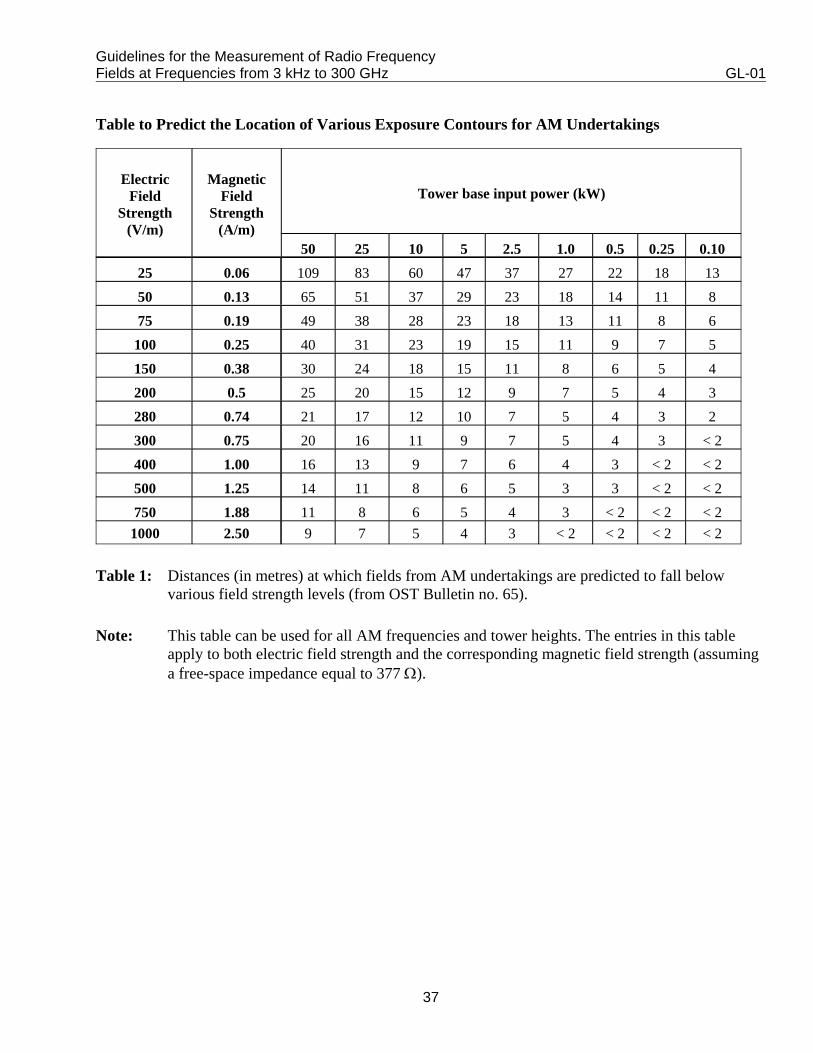
Guidelines for the Measurement of Radio Frequency Fields at Frequencies from 3 kHz to 300 GHz GL-01
37
Table to Predict the Location of Various Exposure Contours for AM Undertakings
ElectricField
Strength(V/m)
MagneticField
Strength(A/m)
Tower base input power (kW)
50 25 10 5 2.5 1.0 0.5 0.25 0.1025 0.06 109 83 60 47 37 27 22 18 1350 0.13 65 51 37 29 23 18 14 11 875 0.19 49 38 28 23 18 13 11 8 6
100 0.25 40 31 23 19 15 11 9 7 5150 0.38 30 24 18 15 11 8 6 5 4200 0.5 25 20 15 12 9 7 5 4 3280 0.74 21 17 12 10 7 5 4 3 2300 0.75 20 16 11 9 7 5 4 3 < 2400 1.00 16 13 9 7 6 4 3 < 2 < 2500 1.25 14 11 8 6 5 3 3 < 2 < 2750 1.88 11 8 6 5 4 3 < 2 < 2 < 2
1000 2.50 9 7 5 4 3 < 2 < 2 < 2 < 2
Table 1: Distances (in metres) at which fields from AM undertakings are predicted to fall belowvarious field strength levels (from OST Bulletin no. 65).
Note: This table can be used for all AM frequencies and tower heights. The entries in this tableapply to both electric field strength and the corresponding magnetic field strength (assuminga free-space impedance equal to 377 Ω).

Guidelines for the Measurement of Radio Frequency Fields at Frequencies from 3 kHz to 300 GHz GL-01
38
Appendix 2 - Measurement Procedure for Microwave Installations
1. Measurement Precautions
1.1 Field measurements should be performed only by qualified personnel, who have a goodunderstanding of electromagnetic radiation and communication systems.
1.2 To minimize measurement errors, refer to survey meter manufacturer’s guidelines regarding:
(a) environmental conditions appropriate for survey meter use (e.g. min/max limits ontemperature, humidity and atmospheric pressure to maintain probe accuracy);
(b) precautions to be taken in the handling of probes to minimize lead pick-up and effects ofsurveyor’s body (e.g. probe to be held out at arm’s length facing radiator or at a right angleto the radiator, moving probe cable to see if reading is affected);
(c) symptoms of survey meter overload and precautions to be taken to avoid overload; and
(d) uncertainty of measurements taken in the presence of reflecting objects and multipleradiating sources.
1.3 The procedures that follow assume near field conditions and metering capable of indicatingboth E and H in units of V2/m2 and A2/m2, respectively. Conversion errors may be encounteredusing metering in the near field while displaying power density (which assumes far fieldconditions).
2. Related Documents
Reference documents are listed below:
• Health Canada, Limits of Human Exposure to Radiofrequency Electromagnetic Fields in theFrequency Range from 3 kHz to 300 GHz, Safety Code 6, 1999.
• "Evaluating Compliance with FCC Guidelines for Human Exposure to RadiofrequencyElectromagnetic Fields", Federal Communications Commission/Office of Engineering andTechnology, OET Bulletin 65, August 1997.
• "IEEE Recommended Practice for the Measurement of Potentially Hazardous ElectromagneticFields - RF and Microwave", IEEE STD C95.3-1991, Institute of Electrical and ElectronicEngineers, 1991.
Guidelines for the Measurement of Radio Frequency Fields at Frequencies from 3 kHz to 300 GHz GL-01
39
3. Initial Preparation Before Site Visit
3.1 Establish and record the following information relating to the equipment being surveyed:
(a) equipment manufacturer, model and nomenclature;
(b) operating frequencies;
(c) transmit power;
(d) transmitting equipment LO, IF and other frequencies below 300 MHz (for H-fieldmeasurements);
(e) transmit antenna gain, beamwidth, antenna orientation (if in fixed position) or rotationangle (less than or equal to 360 degrees) and antenna dimensions;
(f) intended antenna coverage area and sector blanking (if applicable);
(g) typical duty cycle or duration of a typical (or worst-case) transmission; and
(h) applicable maximum exposure limit (MEL) from Safety Code 6.
3.2 Determine the conditions for the survey, from the list below, after discussions with technicaland operations personnel:
(a) typical or worst-case equipment operating conditions;
(b) the worst-case failure mode;
(c) various frequency settings;
(d) various transmitter power levels for different modes of operation;
(e) fixed or normal antenna scan rates; and
(f) maximum transmitter power into a dummy load (if applicable).
3.3 Note any operational or technical irregularities.
3.4 Obtain a copy of previous survey results (if available) for comparison purposes.

Guidelines for the Measurement of Radio Frequency Fields at Frequencies from 3 kHz to 300 GHz GL-01
40
3.5 Verify that the measurement instrumentation system will accurately measure the modulationschemes, frequency range and expected levels of interest.
4. Report Requirements
4.1 Refer to the current version of Safety Code 6 for reporting requirements.
4.2 Data may be presented as written dialogue within the main body of the survey report, intabular form or on a site map, equipment room floor plan or equipment rack layout. Thefavoured method is to present survey data graphically on a top-down view of the surveyedlocation such as a site map or a floor plan, or on views of the transmitting equipment racklayouts.
4.3 Obtain copies of site plan and building floor plan and equipment rack layouts. Each drawingshould include all prominent physical structures and/or equipment. Make multiple copies asrequired on which to mark the test data for the different equipment parameters and testconditions listed in paragraphs 3.1 to 3.3, applicable measurement parameter (i.e. E or H ),applicable general public or RF worker MELs and theoretical assessments of radiationexposures.
4.4 Within the report, clearly identify all over-exposure conditions and the locations where theapplicable general public or RF worker MELs are reached or exceeded.
4.5 Photographs of the site, equipment room(s) and equipment rack(s) where high radiation levelsare measured, would be useful for reference purposes.
4.6 Refer to paragraphs 3.1 to 3.4 for documenting equipment parameters and survey/testconditions.
5. Theoretical Assessment of Radiation Exposures
5.1 Refer to SC6 for theoretical estimation of exposure risk. Estimate the radial distance from theradiator, within the antenna coverage area, for which radiated levels will likely not exceedgeneral public and RF worker exposure levels. The survey should begin at this distance fromthe radiator to reduce the risk of over-exposure to survey personnel and damaging the surveymeter. Estimate whether the radiated fields to be surveyed exist under far field conditions.
Guidelines for the Measurement of Radio Frequency Fields at Frequencies from 3 kHz to 300 GHz GL-01
41
6. Measurement Preliminaries On-site
6.1 Visually examine the area to be surveyed to identify:
(a) areas in which people may be physically located or pass by in transit;
(b) general public and RF worker-only areas;
(c) transmit antenna coverage area;
(d) potential re-radiators of RF energy; and
(e) metallic structures which people may grasp by hand. (Required for contact currentmeasurements.)
6.2 Address the concerns and questions of site personnel as this may indicate the requirement foradditional testing.
7. Measurement of Radiation Exposures
7.1 Consider which of the following is applicable:
If the radiator is not highly directional (i.e. beamwidth > 30 degrees), then assume far fieldconditions exist beyond a one metre distance for frequencies above 300 MHz. If it is estimatedthat far field conditions exist, then SC6 permits the measurement of either E, H or PD.
If it is estimated that near field conditions exist, then SC6 requires separate E and Hmeasurements within the operating range of commercially available survey instrumentation.However, if it unknown whether near field or far field conditions exist, then assume near fieldconditions and separately measure both E and H.
7.2 The data recording procedures are as described in Section 3.
7.3 Begin the survey with the measurement of E. For ease of comparison and explanation of datato interested parties, V/m is the preferred unit of measurement. Using the manufacturers’recommended procedures, verify the operation and calibration of the survey meter withappropriate field sensor head attached.
7.4 Approach the radiator from within the antenna coverage area, starting from a distance greaterthan the estimated general public distance. Observe the following when taking measurements:
Guidelines for the Measurement of Radio Frequency Fields at Frequencies from 3 kHz to 300 GHz GL-01
42
(a) approach the radiator by walking in a serpentine motion (i.e. left to right and then backagain) across the antenna coverage area;
(b) monitor the meter instrumentation while motioning the field probe up and down, or in acircular pattern, between the knees to the top of the head;
(c) do not position your body between the radiator and the field probe. Rather, position thebody so that it is to the side of the radiator-to-field-probe axis. This minimizes reflectionsby the body; and
(d) do not survey within 20 cm of any metallic surface or conductor.
7.5 Approach the radiator from one side of the antenna coverage area. Record the location,distance and angle from the radiator at which MELs are obtained.
7.6 Survey all areas where people may be physically located or pass by in transit and record thedata.
7.7 Survey about all potential re-radiators near where people may be physically located or pass byin transit and record the data.
7.8 Refer to SC6 to determine if higher limits than the specified MELs are permissible formaximum exposure duration for time periods less than 0.1 hour.
7.9 Perform time averaging measurements should the radiated field change significantly (morethan 25% per SC6) within a period of 0.1 hours, as first determined by using the maximumpeak hold feature on the survey meter to record maximum change over time; otherwise a singlemeasurement is sufficient. SC6 details the procedures to follow. Record the exposure levelsincorporating time averaging. Compare these data against the applicable MEL to determine ifan over-exposure condition exists.
7.10 Perform spatial averaging measurements wherever an over-exposure condition is noted. Wherethe field is reasonably uniform (within ± 25% per SC6), as in the far field for example,measurements in one location representative of where people may be physically located, aresufficient. SC6 details the procedures to follow. Record the exposure levels incorporatingspatial averaging. Compare these data against the applicable MEL to determine if anover-exposure condition exists.
7.11 Compare measurements with previous survey results and investigate any obviousdiscrepancies.
7.12 Peak electric field strength measurements are only required in the vicinity of electromagneticpulse (EMP) simulators.
Guidelines for the Measurement of Radio Frequency Fields at Frequencies from 3 kHz to 300 GHz GL-01
43
7.13 Wherever MELs are reached or exceeded, repeat paragraphs 7.3 to 7.10, using instrumentationto measure H, in units of A2/m2.
7.14 Repeat the steps for all conditions of interest as determined by paragraphs 3.1 to 3.3.
8. Induced Current Measurements
8.1 Determine the minimal set of survey locations applicable to Induced Current measurementprogram by the following:
Identify those locations and equipment operating conditions for which the above radiativemeasurement program produced over-exposure conditions before spatial and time averagingwere applied;
From this set, identify those locations for which the equipment being surveyed was operatingwithin the frequency range for which induced current measurements are applicable. (Refer toSC6); and
Identify those locations, if any, where there are long vertical metallic lengths. Examplesinclude metallic poles, stands, stanchions, fence posts, hoists and cables. Add these locations toabove set of minimal survey locations for induced current measurements.
8.2 Position the human model complete with tripod assembly at the first measurement location.
8.3 Calibrate/Zero the survey instrumentation.
8.4 Power ON the equipment at an appropriate equipment operating condition. Record the inducedcurrent produced by the test instrumentation. Do not apply time or spatial averaging to themeasured results.
8.5 Repeat for all radiation over-exposure conditions and for all applicable equipment operatingconditions.
8.6 Most induced current meters develop measurement data valid for both feet. For datacomparison against the single foot MEL condition, as required by SC6, it is valid to measurethe current through both feet and then divide by two if using this type of instrument.
8.7 Refer to SC6 to determine if higher limits than the specified MELs are permissible formaximum exposure duration for time periods less than 0.1 hour.
8.8 Perform time averaging measurements or investigations should the radiated field changesignificantly (more than 25% per SC6) within a period of 0.1 hours. Otherwise a single
Guidelines for the Measurement of Radio Frequency Fields at Frequencies from 3 kHz to 300 GHz GL-01
44
measurement is sufficient. SC6 details the procedures to follow. Record the exposure levelsincorporating time averaging. Compare this data against the applicable MEL to determine if anover-exposure condition does indeed exist.
8.9 Perform spatial averaging measurements wherever an over-exposure condition is noted.(Where the field is reasonably uniform (within ± 25% per SC6), as in the far field for example,a single measurements is sufficient). SC6 details the procedures to follow. Record the exposurelevels incorporating spatial averaging. Compare this data against the applicable MEL todetermine if an over-exposure condition does indeed exist.
9. Contact Current Measurements
9.1 Determine the minimal set of survey locations applicable to contact current measurementprogram by the following:
(a) identify those locations were the radiation measurements produced over-exposure resultsbefore spatial and time averaging were applied;
(b) from this set, identify those locations for which the equipment being surveyed wasoperating within the frequency range for which contact current measurements areapplicable. (Refer to SC6);
(c) from this set, identify those locations for which a person may come into contact with ametallic object by hand-grip. Select these the locations as where contact currentmeasurements are required as a minimum; and
(d) identify those locations, if any, where there are long, vertical metallic lengths or sharpmetallic edges. (Examples include metallic poles, stands, stanchions, fence posts, hoistsand cables). Add these locations to the above set of minimal survey locations for contactcurrent measurements.
9.2 Position the test instrumentation ground plate and meter on ground or floor level, at the firstmeasurement location.
9.3 Fully extend the test instrumentation cabling connecting the ground plate to the meter probe tipassembly in a vertical plane. Ensure the cable pair between the ground plate and meter probetip assembly are not twisted. Ensure the cable pair maintains a fixed separation distancebetween each other. Touch the meter probe tip assembly at the metallic location where aperson may hand grip metal.
9.4 Calibrate/Zero the survey instrumentation.

Guidelines for the Measurement of Radio Frequency Fields at Frequencies from 3 kHz to 300 GHz GL-01
45
9.5 Power ON the equipment at an appropriate equipment operating condition. Record the contactcurrent produced by the test instrumentation. Do not apply time or spatial averaging to themeasured results.
9.6 Repeat for all radiative over-exposure conditions and for all applicable equipment operatingconditions.
9.7 Most contact current meters develop measurement data valid for both feet. For datacomparison against the single foot MEL condition, as required by SC6, it is valid to measurethe current through both feet and then divide by two if using this type of instrument.
9.8 Refer to SC6 to determine if higher limits than the specified MELs are permissible formaximum exposure duration for time periods less than 0.1 hour.
9.9 Perform time averaging measurements or investigations should the radiated field changesignificantly (more than 25% per SC6) within a period of 0.1 hours. Otherwise a singlemeasurement is sufficient. SC6 details the procedures to follow. Record the exposure levelsincorporating and time averaging. Compare this data against the applicable MEL to determineif an over-exposure condition does indeed exist.
9.10 Perform spatial averaging measurements wherever an over-exposure condition is noted.(Where the field is reasonably uniform (within ± 25% per SC6), as in the far field for example,a single measurements is sufficient). SC6 details the procedures to follow. Record the exposurelevels incorporating spatial averaging. Compare this data against the applicable MEL todetermine if an over-exposure condition does indeed exist.
10. Radiation Measurements about Transmitting Equipment
10.1 The procedures that follow are applicable to radiation measurements on in-service transmittingequipment in equipment rooms and equipment bays, about equipment maintenance/workshopareas and calibration centres.
10.2 Inspect cabinet interlocks to ensure they are operating satisfactorily. Discuss maintenance andoperational procedures about the transmitting cabinets performed by maintenance andoperational support staff. For example, determine if cabinet door interlocks are defeated forrepair or calibration procedures. Test equipment operating under these non-standard interlockconfigurations.
10.3 The data recording procedures are as described in Section 4 of GL-001.
Guidelines for the Measurement of Radio Frequency Fields at Frequencies from 3 kHz to 300 GHz GL-01
46
10.4 Using a calibrated meter with E field probe, survey all personnel workstation areas. Surveythose areas where personnel may position themselves or position their body extremities such asarms and hands.
10.5 Visually examine all waveguide joints for indications of high-voltage arcing, in areas wherepersonnel may position themselves or position their body extremities. If waveguide arcing isnoted, immediately report it to the equipment maintainers. Cease operation of the transmittingsystem until the source of the problem has been identified and corrected.
10.6 Survey along RF output power cables, operating dummy loads, exterior waveguides, spacesbetween rack panels, etc. Note locations of standing waves. Ignore all measurements madewithin 20 cm of a metallic surface, cable or RF device.
10.7 For each over-exposure condition, and for all equipment racks generating RF energy atfrequencies below 300 MHz, repeat the measurements with a magnetic (H field) probe andrecord the levels found.
10.8 Refer to SC6 to determine if higher limits than the specified MELs are permissible formaximum exposure duration for time periods less than 0.1 hour.
10.9 Perform time averaging measurements should the radiated field change significantly (morethan 25% per SC6) within a period of 0.1 hours, as first determined by using the maximumpeak hold feature on the survey meter to record maximum change over time; otherwise a singlemeasurement is sufficient. SC6 details the procedures to follow. Record the exposure levelsincorporating time averaging. Compare these data against the applicable MEL to determine ifan over-exposure condition exists.
10.10 Perform spatial averaging measurements wherever an over-exposure condition is noted. Wherethe field is reasonably uniform (within ± 25% per SC6), as in the far field for example,measurements in one location representative of where people may be physically located, aresufficient. SC6 details the procedures to follow. Record the exposure levels incorporatingspatial averaging. Compare these data against the applicable MEL to determine if an over-exposure condition exists.
10.11 Compare measurements with previous survey results and investigate any obviousdiscrepancies.
10.12 Peak electric field strength measurements are only required in the vicinity of EMP simulators.
Guidelines for the Measurement of Radio Frequency Fields at Frequencies from 3 kHz to 300 GHz GL-01
47
11. Abbreviations and Acronyms
H Magnetic FieldPD Power DensitySC6 Health Canada’s Safety Code 6
E Electric FieldMEL Maximum Exposure Level (from SC6)RF Radiofrequency
Guidelines for the Measurement of Radio Frequency Fields at Frequencies from 3 kHz to 300 GHz GL-01
48
Appendix 3
Section A - Procedures for Measuring the Levels of RFEnergy Associated With Land Mobile, Cellular and PCS Services
1. Introduction
This appendix covers transmitting facilities involving land mobile, paging, two-way, trunking, cellularand PCS services, operating in the frequency range of 30 MHz to 2 GHz. Field measurements should beperformed by qualified personnel who have a good understanding of wireless operations and facilities.All channels should be turned on at the same time and operating at full power to achieve worst-casesituations.
2. Related Documents
Pertinent documents on the subject of non-ionizing radiation (NIR) are listed below:
• Health Canada, Limits of Human Exposure to Radiofrequency Electromagnetic Fields in theFrequency Range from 3 kHz to 300 GHz, Safety Code 6, 1999.
• CRC Predict Program - Propagation Prediction Program developed by Communications ResearchCentre for the VHF / UHF Radio Frequency Bands.
• Radio Frequency Power Density calculation Tool ( RaPD Tool). Members can obtain a copy fromthe CWTA. Otherwise, copies are available from Previse Inc.
3. Initial Preparation
3.1 Station and Site Information
3.1.1 One should obtain the pertinent station and site parameters prior to conducting the survey, butif the information is not complete, collect the necessary data at the site.
Station and site parameters include:
Location - geographical coordinates using GPS- ground elevation - above mean sea level (AMSL)
Guidelines for the Measurement of Radio Frequency Fields at Frequencies from 3 kHz to 300 GHz GL-01
49
Structure - type: rooftop or tower- height - above ground level (AGL)
Antenna - the number of antennas located at the site- height (with respect to the floor or ground)- manufacturer- model- azimuth- elevation angle- gain- antenna patterns- operating frequency range- polarization- mechanical dimensions
Transmitters - number of transmitters - transmit power- transmission line loss- operating frequency
Ancillary equipment
3.1.2 Nearby transmitting stations may affect the field readings, therefore they should be taken intoaccount in the prediction of the flux density at each test point. In general, databases and mapsshould be searched for any transmitting station within a radius of 200 m of the survey site andany high-power transmissions (e.g. AM broadcasting or radar) within 2 km.
Note: When dealing with an antenna farm, a copy of the site drawing indicating the antennalayout, relative position and site characteristics should be obtained. Photos would alsobe helpful.
3.2 Theoretical Estimate
3.2.1 Establishing grids for measurements around survey station
3.2.1.1 If multiple transmitting antennas are present at various locations at the site, designate a singlereference point for estimation purposes.
3.2.1.2 Calculate the distance from the reference point to where the far field begins, using theappropriate equation.
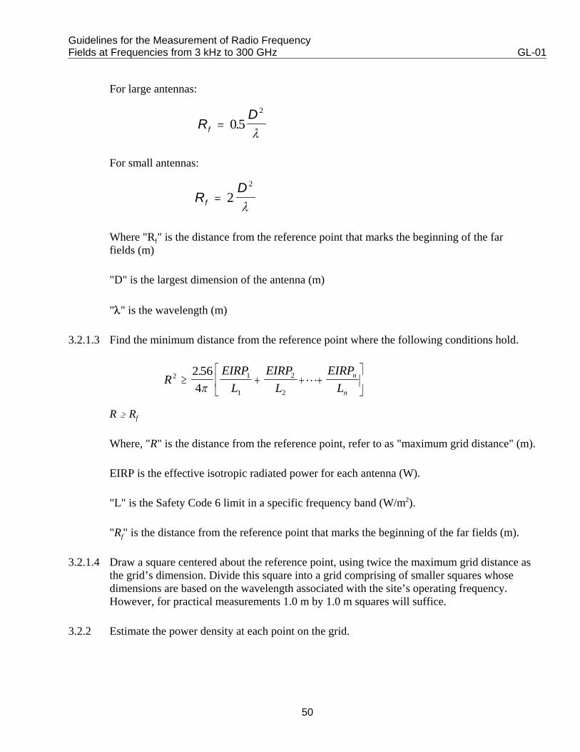
Guidelines for the Measurement of Radio Frequency Fields at Frequencies from 3 kHz to 300 GHz GL-01
50
RD
f = 052
.λ
RD
f = 22
λ
REIRP
LEIRP
LEIRP
Ln
n
2 1
1
2
2
2 564
≥ + + +⎡
⎣⎢
⎤
⎦⎥
.π
L
For large antennas:
For small antennas:
Where "Rf" is the distance from the reference point that marks the beginning of the farfields (m)
"D" is the largest dimension of the antenna (m)
"λ" is the wavelength (m)
3.2.1.3 Find the minimum distance from the reference point where the following conditions hold.
R $ Rf
Where, "R" is the distance from the reference point, refer to as "maximum grid distance" (m).
EIRP is the effective isotropic radiated power for each antenna (W).
"L" is the Safety Code 6 limit in a specific frequency band (W/m2).
"Rf" is the distance from the reference point that marks the beginning of the far fields (m).
3.2.1.4 Draw a square centered about the reference point, using twice the maximum grid distance asthe grid’s dimension. Divide this square into a grid comprising of smaller squares whosedimensions are based on the wavelength associated with the site’s operating frequency.However, for practical measurements 1.0 m by 1.0 m squares will suffice.
3.2.2 Estimate the power density at each point on the grid.
Guidelines for the Measurement of Radio Frequency Fields at Frequencies from 3 kHz to 300 GHz GL-01
51
The power density of each point on the grid can be calculated using RaPD Tool or anyappropriate formula.
3.2.3 Select the points to be measured points that are 50% or more of the Safety Code 6 exposurelimit as points to be measured at the site and plot them on the grid. For those points less than50% of the Safety Code 6 limit, no measurement need be taken. When arriving at the site,additional points should be measured in publicly accessible areas (including roof top ofbuildings where maintenance work may be required) and areas of potential re-radiating RFenergy.
3.3 Equipment Selection and Verification
3.3.1 Select equipment with the following characteristics:
• covers the operating frequency range to be measured;• operates in a high RF field strength environment; and• operates in the climate and weather condition of the survey locations.
The surveyor should have good knowledge of the equipment and probe (e.g. polarization,behaviour, orientation and the rotation needed to obtain maximum and minimum readings).
3.3.2 Verify that the equipment is calibrated and working correctly. Record the calibration date, theserial number, manufacturer and model of the equipment being used. If the meter is batteryoperated, ensure that it is fully charged.
3.4 Record Sheet
Set up a recording table, corresponding to the grid, of all points to be measured at the site. There shouldbe at least three columns in the table: the point’s relative position, the time the reading was taken, andthe reading itself. An area of the sheet should be set up to enter the antenna and transmitter parameters,information regarding the equipment used for the survey, the date, and the weather during the survey.Draw or obtain drawings of the equipment room and test site, noting the relative positions of theantennas, and attach them to the record sheet.
4. Measurement Steps
4.1 Verification
4.1.1 Calibrate and test the probe to ensure it is functioning correctly before taking anymeasurements, as recommended by the manufacturer.
Guidelines for the Measurement of Radio Frequency Fields at Frequencies from 3 kHz to 300 GHz GL-01
52
4.1.2 Perform a rapid walk around the site with the general probe, set in the maximum hold position,beginning away from the antenna and walking in, moving the probe in a constant up and down,side to side motion. This procedure is to ensure that the surveyor is not at risk of over-exposure. If the readings exceed the RF worker limit, retreat and note the location.
4.1.3 If the equipment room is not located in an area that exceeds the RF worker limit, perform aquick walk around with the general probe to ensure that the room itself is within the RF workerlimit. If not, exit the premise immediately and notify the manager.
If the initial readings indicate that the room is within the limits set out in Safety Code 6, checkto ensure that there are the same number of transmitters as specified in the preparationcalculations. If any of the initial preparation information is contrary to the actual operationsetup then recalculate the theoretical estimate with the new data gathered at the site. If all is asexpected, continue with the survey.
4.1.4 Verify that the site reflects the description used in the theoretical calculations, by counting thenumber of antennas, and noting their layout.
4.2 Measurement of RF Energy
4.2.1 Construct the grid and record the locations of any additional points to be measured on the map(e.g. areas that are publicly accessible and of potential radiating of RF energy).
4.2.2 Approach the points of interest within the grid, starting at the point furthest from the antenna orreference point. Moving the probe in a constant up and down, side-to-side motion (at arm'slength) at the specific location, note the variation in readings. If there is little variation in thereadings, relative to the accuracy of the instrument, then measure the power density at 1.5 mabove the floor or ground. Record these values on the record sheet. However if there is a largevariation, greater than 110% of the relative accuracy of the instrument, spatial averaging isrecommended as per Safety Code 6.
4.2.3 Do not position the body between the antenna and the field probe. Rather position the body sothat it is to the side of the antenna-to-field probe axis. This minimizes reflections by the body.Do not take measurements closer than 20 cm from potentially reflective objects. Note: Presently there are no commercially available H field probes beyond 300 MHz.
4.3 Multiple Sources
Some probes are able to measure all frequencies at once so if this type of probe is used then measure allthe sources at once. To ensure that all live transmitters are keyed during the test, turn on one by one,checking at all times that the meter reading has increased, reflecting the addition of each transmitter.
Guidelines for the Measurement of Radio Frequency Fields at Frequencies from 3 kHz to 300 GHz GL-01
53
If several probes are needed to cover the entire operating frequency range of the site, attention should bepaid so that no transmitter is measured twice. Key each transmitter one by one until all transmitterswithin the first probe’s range have been keyed, checking that the meter reading increases, reflecting theaddition of each transmitter. Measure the power density at each point, then, turn off the transmitters.Key the next transmitters (those that have not already been turned on) one by one, that fall into thesecond probe’s range, and measure the power density at each point. Repeat the procedure until alltransmitters have been keyed once.
For narrowband receivers, key one transmitter at a time and measure the power density at each point.Repeat this procedure for the remaining transmitters.
5. RF Contact and Induced Currents
For these services, RF contact and induced body currents are not significant. However, it isrecommended not to come in direct contact with any metallic surfaces to avoid a shock due to impropergrounding.
6. Report
Include in the report:
• a description of the survey site, transmitting facility and photographs if available;
• any observations regarding the climate, time of day, and anything unusual regarding the site orsources;
• a list of technical parameters of the antennas and transmitters including frequency, power, asmentioned in the initial preparation;
• the equipment used (serial number, and manufacturer) along with the calibration date of theinstrumentation, so others can repeat the survey;
• the copies of the site map with each of the tested locations clearly identified and the correspondingreadings, highlighting those points in excess of 50% of the safety limit;
• a statement of compliance or non-compliance to Safety Code 6 limits; and
• suggestions where appropriate.
Guidelines for the Measurement of Radio Frequency Fields at Frequencies from 3 kHz to 300 GHz GL-01
54
Section B - Procedures for Measuring the Levels of RF Energy Associated with the Portable and Mobile Units of Land Mobile, Cellular and PCS Services
Measurement procedures for the portable and mobile units of Land Mobile, Cellular and PCS Services,please refer to Industry Canada's Radio Standards Specification 102, Issue 2, Radio Frequency ExposureCompliance of Radiocommunication Apparatus (All Frequency Bands) (RSS-102).
Guidelines for the Measurement of Radio Frequency Fields at Frequencies from 3 kHz to 300 GHz GL-01
55
Appendix 4 - Measurement Procedures for Radar Installations
1. Measurement Precautions
1.1 Field measurements should be performed only by qualified personnel, who have a goodunderstanding of electromagnetic radiation and radar systems.
1.2 In cases where there is a predicted or known risk of over-exposure to survey personnel, one offour survey approaches may be used depending on the risk assessment;
(a) For high-risk cases, a horn antenna can be placed inside the measurement area (while theradar transmitter is OFF) and connected to a spectrum analyzer with a low-loss cable ofsufficient length to permit data to be taken without risk of overexposure.
(b) For medium risk cases, survey instrumentation may be placed on a tripod inside themeasurement area (while the radar transmitter is OFF) and the meter is read withbinoculars or via an optical link.
(c) For low risk cases, the survey probe may be used for an initial assessment.
(d) Alternately, where it is not necessary that the transmitter operate at full power, thetransmitter may be operated at a reduced power level and the data adjusted to take thispower reduction into account.
1.3 Where test procedures require a stationary radar beam. Personnel must be vacated frominhabited areas that will be radiated by, either the main beam, or secondary lobes or reflectionsfrom the main beam or secondary lobes.
1.4 For measurements on a scanning/rotating antenna, maintain the position of the survey probelong enough to permit the measurement of several sweeps of the antenna. Ensure that theresponse time of the survey instrument is fast enough for this type of measurement.
1.5 The radar transmitter shall not be tested without an appropriate load.
1.6 Ensure that there is sufficient clearance between a scanning/rotating antenna and surveypersonnel to avoid physical injury. Throughout the survey, survey personnel should be inconstant communication with the radar operator in order to implement parameter changesrequired by the test program and to be able to quickly curtail transmitter operation in case ofemergency.
Guidelines for the Measurement of Radio Frequency Fields at Frequencies from 3 kHz to 300 GHz GL-01
56
1.7 To minimize measurement errors, refer to survey meter manufacturer’s guidelines regarding:
(a) Environmental conditions appropriate for survey meter use (e.g. min/max limits ontemperature, humidity and atmospheric pressure to maintain probe accuracy).
(b) Precautions to be taken in the handling of probes to minimize lead pick-up and effects ofsurveyor’s body (e.g. probe to be held out at arm’s length facing radiator or at a right angleto the radiator, moving probe cable to see if reading is affected).
(c) Symptoms of survey meter overload and precautions to be taken to avoid overload.
(d) Uncertainty of measurements taken in the presence of reflecting objects and multipleradiating sources.
1.8 The procedures that follow assume near field conditions and metering capable of indicating Eand H in units of V2/m2 and A2/m2, respectively. Conversion errors may be encountered usingmetering in the near field while displaying power density (which assumes far field conditions).
2. Related Documents
Reference documents are listed below:
• Health Canada, Limits of Human Exposure to Radiofrequency Electromagnetic Fields in theFrequency Range from 3 kHz to 300 GHz, Safety Code 6, 1999.
• "Evaluating Compliance with FCC Guidelines for Human Exposure to RadiofrequencyElectromagnetic Fields", Federal Communications Commission/Office of Engineering andTechnology, OET Bulletin 65, August 1997.
• "IEEE Recommended Practice for the Measurement of Potentially Hazardous ElectromagneticFields – RF and Microwave", IEEE STD. C95.3-1991, Institute of Electrical and ElectronicEngineers, 1991.
3. Initial Preparation Before Site Visit
3.1 Establish and record the following information relating to the equipment being surveyed:
(a) equipment manufacturer, model and nomenclature;
(b) operating frequencies;

Guidelines for the Measurement of Radio Frequency Fields at Frequencies from 3 kHz to 300 GHz GL-01
57
(c) transmit peak power, pulse duration and pulse repetition rate;
(d) transmitting equipment LO, IF and other frequencies below 300 MHz (for H fieldmeasurements);
(e) transmit antenna gain, beamwidth, antenna orientation (if in fixed position) or rotationangle (less than or equal to 360 degrees) and antenna dimensions;
(f) intended antenna coverage area (i.e. the area swept by the scanning antenna) and sectorblanking (if applicable);
(g) typical duty cycle or duration of a typical (or worst-case) transmission;
(h) applicable maximum exposure limit (MEL) from Safety Code 6.
3.2 Determine the conditions for the survey, from the list below, after discussions with technicaland operations personnel:
(a) under typical or worst-case equipment operating conditions;
(b) under the worst-case failure mode;
(c) at various frequency settings;
(d) at various transmitter power levels and pulse widths for different modes of operation;
(e) at fixed or normal antenna scan rates; and
(f) at maximum transmitter power into the dummy load.
3.3 Note any operational or technical irregularities.
3.4 Obtain a copy of previous survey results (if available) for comparison purposes.
3.5 Verify that the measurement instrumentation system will accurately measure the modulationschemes, frequency range and expected levels of interest.
Guidelines for the Measurement of Radio Frequency Fields at Frequencies from 3 kHz to 300 GHz GL-01
58
4. Report Requirements
4.1 Refer to current SC6 for reporting requirements.
4.2 Data may be presented as written dialogue within the main body of the survey report, in tabularform or on a site map, equipment room floor plan or equipment rack layout. The favouredmethod is to present survey data graphically on a top-down view of the surveyed location suchas a site map or a floor plan, or on views of the transmitting equipment rack layouts.
4.3 Obtain copies of site plan and building floor plan and equipment rack layouts. Each drawingshould include all prominent physical structures and/or equipment. Make multiple copies asrequired on which to mark the test data for the different test conditions identified inparagraph 3.2, applicable measurement parameter (i.e. E or H), applicable general public or RFworker MELs and theoretical assessments of radiation exposures.
4.4 Within the report, clearly identify all over-exposure conditions and the locations where theapplicable general public and/or RF worker MELs are reached or exceeded.
4.5 Photographs of the site, equipment room(s) and equipment rack(s) where high radiation levelsare measured, would be useful for reference purposes.
4.6 Refer to paragraphs 3.1 to 3.4 for documenting equipment parameters and test conditions.
5. Theoretical Assessment of Radiation Exposures
5.1 Refer to SC6 for theoretical estimation of exposure risk. Estimate the radial distance from theradiator, within the antenna coverage area, for which radiated levels will likely not exceedgeneral public and RF worker exposure limits. The survey should begin at this distance fromthe radiator to reduce the risk of over-exposure to survey personnel and damaging the surveymeter. Estimate whether the radiated fields to be surveyed exist under far field conditions.
6. Measurement Preliminaries On-site
6.1 Visually examine the area to be surveyed to identify:
(a) areas in which people may be physically located or pass by in transit;
(b) general public and RF worker-only areas;
(c) transmit antenna coverage area and sector blanked area; and
Guidelines for the Measurement of Radio Frequency Fields at Frequencies from 3 kHz to 300 GHz GL-01
59
(d) potential re-radiators of RF energy.
6.2 Address the concerns and questions of site personnel as this may indicate the requirement foradditional testing.
7. Measurement of Radiation Exposures
7.1 The data recording procedures are as described in Section 4 of GL-001.
7.2 Begin the survey with the measurement of E. For ease of comparison and explanation of data tointerested parties, V/m is the preferred unit of measurement. Using the manufacturers’recommended procedures, verify the operation and calibration of the survey meter withappropriate field sensor head attached.
7.3 When testing a stationary antenna for a selected radar operating condition, defeat antennarotation. Then, manually adjust antenna angles such that a worst-case condition is achieved.Otherwise, incorporate the antenna rotational reduction factor into the measurement data asdetailed in SC6.
7.4 Approach the radiator from within the antenna coverage area, starting from a distance greaterthan the estimated "general public" distance. Observe the following when takingmeasurements:
(a) Approach the radiator by walking in a serpentine motion (i.e. left to right and then backagain) across the antenna coverage area.
(b) Monitor the meter instrumentation while motioning the field probe up and down, or in acircular pattern, between the knees to the top of the head.
(c) Use the maximum peak hold feature on the survey meter for a sufficiently long period toensure that maximum amplitude of the pulses and the sweeps (if the antenna is rotating)have been measured.
(d) Do not position your body between the radiator and the field probe. Rather, position thebody so that it is to the side of the radiator-to-field-probe axis. This minimizes reflectionsby the body.
(e) Do not survey within 20 cm of any metallic surface or conductor.
(f) Take into consideration the field strength of the back lobe. Under certain conditions thesurvey meter could be damaged.
Guidelines for the Measurement of Radio Frequency Fields at Frequencies from 3 kHz to 300 GHz GL-01
60
7.5 Survey all areas where people may be physically located or pass by in transit and record thedata.
7.6 Survey about all potential re-radiators near where people may be physically located or pass byin transit and record the data.
7.7 Incorporate the antenna rotational reduction factor into the measurement data as detailed inSC6 if MELs are exceeded.
7.8 Refer to SC6 to determine if higher limits than the specified MELs are permissible formaximum exposure duration for time periods less than 0.1 hour.
7.9 Perform time averaging measurements should the radiated field change significantly (morethan 25% per SC6) within a period of 0.1 hours, as first determined by using the maximumpeak hold feature on the survey meter to record maximum change over time; otherwise a singlemeasurement is sufficient. SC6 details the procedures to follow. Record the exposure levelsincorporating time averaging. Compare these data against the applicable MEL to determine ifan over-exposure condition exists.
7.10 Perform spatial averaging measurements wherever an over-exposure condition is noted. Wherethe field is reasonably uniform (within 25% per SC6), as in the far field for example,measurements in one spot representative of where people may be physically located, aresufficient. SC6 details the procedures to follow. Record the exposure levels incorporatingspatial averaging. Compare these data against the applicable MEL to determine if anover-exposure condition exists.
7.11 Compare measurements with previous survey results and investigate any obviousdiscrepancies.
7.12 Repeat the steps described in paragraphs 7.1 to 7.4 for all conditions of interest previouslydetermined in paragraph 3.2.
7.13 Peak electric field strength measurements are only required in the vicinity of electromagneticpulse (EMP) simulators.
8. Radiation Measurements Around Transmitting Equipment
8.1 The procedures, which follow, are applicable to radiation measurements on in-servicetransmitting equipment in equipment rooms and equipment bays, about equipmentmaintenance/workshop areas and calibration centres.
Guidelines for the Measurement of Radio Frequency Fields at Frequencies from 3 kHz to 300 GHz GL-01
61
8.2 Inspect cabinet interlocks to ensure they are operating satisfactorily. Discuss maintenance andoperational procedures about the transmitting cabinets performed by maintenance andoperational support staff. For example, determine if cabinet door interlocks are defeated forrepair or calibration procedures. Test equipment operating under these non-standard interlockconfigurations.
8.3 The data recording procedures are as described in Section 4 of GL-001.
8.4 Using a calibrated meter with E field probe, survey all personnel workstation areas. Surveythose areas where personnel may position themselves or position their body extremities such asarms and hands.
8.5 Visually examine all waveguide joints, in areas where personnel may position themselves orposition their body extremities, for indications of high voltage arcing. If waveguide arcing isnoted, immediately report it to the equipment maintainers. Cease operation of the transmittingsystem until the source of the problem has been identified and corrected.
8.6 Survey along RF output power cables, operating dummy loads, exterior waveguides, spacesbetween rack panels, etc. Note locations of standing waves. Ignore all measurements madewithin 20 cm of a metallic surface, cable or RF device.
8.7 For each over-exposure condition, and for all equipment racks generating RF energy atfrequencies below 300 MHz, repeat the measurements with a magnetic (H-field) probe andrecord the levels found.
8.8 Refer to SC6 to determine if higher limits than the specified MELs are permissible formaximum exposure duration for time periods less than 0.1 hour.
8.9 Perform time averaging measurements should the radiated field change significantly (morethan 25% per SC6) within a period of 0.1 hours, as first determined by using the maximumpeak hold feature on the survey meter to record maximum change over time; otherwise a singlemeasurement is sufficient. SC6 details the procedures to follow. Record the exposure levelsincorporating time averaging. Compare these data against the applicable MEL to determine ifan over-exposure condition exists.
8.10 Perform spatial averaging measurements wherever an over-exposure condition is noted. Wherethe field is reasonably uniform (within ± 25% per SC6), as in the far field for example,measurements in one location representative of where people may be physically located, aresufficient. SC6 details the procedures to follow. Record the exposure levels incorporatingspatial averaging. Compare these data against the applicable MEL to determine if anover-exposure condition exists.
8.11 Compare measurements with previous survey results and investigate any obvious discrepancies.
8.12 Peak electric field strength measurements are only required in the vicinity of EMP simulators.
Guidelines for the Measurement of Radio Frequency Fields at Frequencies from 3 kHz to 300 GHz GL-01
62
Appendix 5 - Guidelines for Measurement Uncertainties
1. Measurement Uncertainties
Measurement uncertainties are the result of actual measurement uncertainties and/or instrumentationuncertainties.
2. Related Documents
For additional information on measurement uncertainties, refer to Measurement Good Practice Guidesby the National Physical Laboratory.
3. Actual Measurement Uncertainties
Actual measurement uncertainties can be minimized by following proper measuring practices andprocedures.
4. Instrumentation Uncertainties
Instrumentation uncertainties are primarily due to the design of the instrument. They can also beaffected by other factors such as environmental conditions, temperature, humidity, etc. Propercalibration of the instrument can largely eliminate the bias errors and a careful selection of instrumenttype and measuring method can reduce the value of this uncertainty factor.
4.1 Recommended Procedures for Compliance with Safety Code 6
a. The instrument selected must be of recognized commercial type.
b. Proper calibration of the instrument must be performed in accordance with the manufacturer'srecommended calibration period.
c. Provided that correct measurement procedures have been followed and proper calibration of theinstrument has been performed, if the measured field strength levels plus the manufacturer's;specified instrument uncertainty factor are below the Safety Code 6 (SC6) limits, these field strengthlevels will be accepted as measured and the site is deemed to be SC6 compliant.
d. If the measured field strength levels plus the manufacturer's specified instrument uncertainty factorexceed the SC6 limits, corrective remedies must be taken to comply with SC6 requirements. Singlefrequency measurement of all frequencies present at the site can be conducted to improve theinstrumentation uncertainty factor.