glass–ceramics in dentistry: a review
TRANSCRIPT
materials
Review
Glass–Ceramics in Dentistry: A Review
Le Fu 1,* , Håkan Engqvist 2 and Wei Xia 2,*1 School of Materials Science and Engineering, Central South University, Changsha 410083, China2 Applied Materials Science, Department of Engineering Science, Uppsala University, 751 21 Uppsala, Sweden;
[email protected]* Correspondence: [email protected] (L.F.); [email protected] (W.X.)
Received: 18 November 2019; Accepted: 22 January 2020; Published: 26 February 2020�����������������
Abstract: In this review, we first briefly introduce the general knowledge of glass–ceramics, includingthe discovery and development, the application, the microstructure, and the manufacturing ofglass–ceramics. Second, the review presents a detailed description of glass–ceramics in dentistry.In this part, the history, property requirements, and manufacturing techniques of dental glass–ceramicsare reviewed. The review provided a brief description of the most prevalent clinically used examples ofdental glass–ceramics, namely, mica, leucite, and lithium disilicate glass–ceramics. In addition, we alsointroduce the newly developed ZrO2–SiO2 nanocrystalline glass–ceramics that show great potential asa new generation of dental glass–ceramics. Traditional strengthening mechanisms of glass–ceramics,including interlocking, ZrO2–reinforced, and thermal residual stress effects, are discussed. Finally,a perspective and outlook for future directions in developing new dental glass–ceramics is providedto offer inspiration to the dental materials community.
Keywords: glass–ceramics; dental prostheses; strength; translucency; strengthening mechanisms
1. The History of Glass–Ceramics and Dental Glass–Ceramics
Synthetic glass–ceramics were serendipitously discovered by Stanley Donald Stookey in 1953. [1–4].After the discovery of lithium disilicate glass–ceramic, Corning Inc. developed and commercializedtwo new glass–ceramics based on Li–aluminosilicates (LAS) and Mg–aluminosilicates (MAS) during1953–1963 [5]. The LAS glass–ceramic was used as cookware because of its very low coefficient ofthermal expansion (CTE). The development of MAS glass–ceramic was motivated by the need arosefor a ceramic missile nosecone for a missile to be guided by an internal antenna [1]. Between 1963and 1980, researchers tried to develop transparent and nano–crystalline glass–ceramics. For instance,nano–crystalline β–quartz glass–ceramic introduced by Schott has a crystalline size of about 50 nm [6].
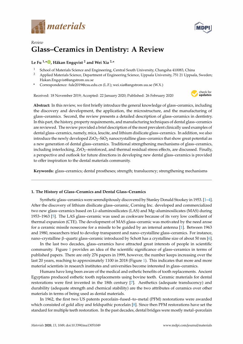
In the last two decades, glass–ceramics have attracted great interests of people in scientificcommunity. Figure 1 provides an idea of the scientific significance of glass–ceramics in terms ofpublished papers. There are only 276 papers in 1999, however, the number keeps increasing over thelast 20 years, reaching to approximately 1100 in 2018 (Figure 1). This indicates that more and morematerial scientists in research institutes and universities become interested in glass–ceramics.
Humans have long been aware of the medical and esthetic benefits of tooth replacements. AncientEgyptians produced esthetic tooth replacements using bovine teeth. Ceramic materials for dentalrestorations were first invented in the 18th century [7]. Aesthetics (adequate translucency) anddurability (adequate strength and chemical stability) are the two attributes of ceramics over othermaterials in terms of being used as dental materials.
In 1962, the first two US patents porcelain–fused–to–metal (PFM) restorations were awardedwhich consisted of gold alloy and feldspathic porcelain [8]. Since then PFM restorations have set thestandard for multiple teeth restoration. In the past decades, dental bridges were mostly metal–porcelain
Materials 2020, 13, 1049; doi:10.3390/ma13051049 www.mdpi.com/journal/materials
Materials 2020, 13, 1049 2 of 22
composite, consisting of a metallic framework for load–bearing and coated porcelain for aestheticappearance [9]. Despite the wide application of PFM restorations, the use of metals in the oral cavityhas come under disputes in recent years because of their biological incompatibility and some otherconcerns, such as chipping of the veneering layer because of the CTE differences between porcelainveneering layer and metallic framework [4,5]. These are the main factors motivating continued researchinto all–ceramic restorations. All–ceramic dental restorations are available on the market since the 1980s.Yttrium–stabilized tetragonal ZrO2 (Y–TZP) has gained remarkable popularity in dentistry because ofits excellent mechanical properties. However, Y–TZP has low translucency. Thus, it still requires aveneering layer constructed with a compatible porcelain in order to achieve a more favorable aestheticresult [10]. This is so–called multilayered dental prostheses. However, the problem of chipping ofthe veneering layer still exists in the multilayered restorations [10]. This drives the development ofmonolithic prostheses with high strength and high translucency in recent years.
Dental glass–ceramics are highly attractive for dentists and patients owing to their combinationof excellent physical and chemical properties, such as outstanding esthetics, translucency, lowthermal conductivity, adequate strength, biocompatibility, wear resistance, and chemical durability [11,12]. In 1984, Corning Inc. was the first company to fabricate glass–ceramic material for dentalrestorations [4,9]. The attempts of developing glass–ceramics with higher strength through chemicalcomposition modification and optimization of the manufacturing process have never ended. Dispersionstrengthening is one of the well–grounded approaches to strengthening glass–ceramic. One of the mostsuccessful particle fillers used in dental glass–ceramics is leucite. One example of commercial dentalceramics containing leucite as a strengthening phase shows a bending strength of ~138 MPa (IvoclarVivadent, Liechtenstein) [13]. Currently, the most widely used, the strongest and toughest dentalglass–ceramics are made with lithium disilicate. The glass–ceramic contains ~70 vol% of interlockedrod–like lithium disilicate crystals. The material possesses a flexural strength of 350 MPa and a fracturetoughness of 2.9 MPa m1/2 [14,15], which were more than twice those of leucite–based glass–ceramics.
This paper reviews some aspects of the field, including microstructure and preparation ofglass–ceramics, manufacturing of dental glass–ceramics, commercial and newly–developed dentalglass–ceramics, strengthening mechanisms, and also our perspective for future directions.
Materials 2019, 12, x FOR PEER REVIEW 2 of 23
standard for multiple teeth restoration. In the past decades, dental bridges were mostly metal–
porcelain composite, consisting of a metallic framework for load–bearing and coated porcelain for
aesthetic appearance [9]. Despite the wide application of PFM restorations, the use of metals in the
oral cavity has come under disputes in recent years because of their biological incompatibility and
some other concerns, such as chipping of the veneering layer because of the CTE differences between
porcelain veneering layer and metallic framework [4,5]. These are the main factors motivating
continued research into all–ceramic restorations. All–ceramic dental restorations are available on the
market since the 1980s. Yttrium–stabilized tetragonal ZrO2 (Y–TZP) has gained remarkable
popularity in dentistry because of its excellent mechanical properties. However, Y–TZP has low
translucency. Thus, it still requires a veneering layer constructed with a compatible porcelain in order
to achieve a more favorable aesthetic result [10]. This is so–called multilayered dental prostheses.
However, the problem of chipping of the veneering layer still exists in the multilayered restorations
[10]. This drives the development of monolithic prostheses with high strength and high translucency
in recent years.
Dental glass–ceramics are highly attractive for dentists and patients owing to their combination
of excellent physical and chemical properties, such as outstanding esthetics, translucency, low
thermal conductivity, adequate strength, biocompatibility, wear resistance, and chemical durability
[11,12]. In 1984, Corning Inc. was the first company to fabricate glass–ceramic material for dental
restorations [4,9]. The attempts of developing glass–ceramics with higher strength through chemical
composition modification and optimization of the manufacturing process have never ended.
Dispersion strengthening is one of the well–grounded approaches to strengthening glass–ceramic.
One of the most successful particle fillers used in dental glass–ceramics is leucite. One example of
commercial dental ceramics containing leucite as a strengthening phase shows a bending strength of
~138 MPa (Ivoclar Vivadent, Liechtenstein) [13]. Currently, the most widely used, the strongest and
toughest dental glass–ceramics are made with lithium disilicate. The glass–ceramic contains ~70 vol%
of interlocked rod–like lithium disilicate crystals. The material possesses a flexural strength of 350
MPa and a fracture toughness of 2.9 MPa m1/2 [14,15], which were more than twice those of leucite–
based glass–ceramics.
This paper reviews some aspects of the field, including microstructure and preparation of glass–
ceramics, manufacturing of dental glass–ceramics, commercial and newly–developed dental glass–
ceramics, strengthening mechanisms, and also our perspective for future directions.
Figure 1. An idea of scientific and commercial significance of glass–ceramics. The number of
published papers searched from Web of Science with the key words “glass–ceramics.”
2. Properties and Applications of Glass–Ceramics
Glass–ceramics have been widely used in a wide range of fields in our daily life, owning to their
challenging combination of properties to fulfil specific requirements. Figure 2 demonstrates some of
1998 2001 2004 2007 2010 2013 2016 20190
200
400
600
800
1000
1200
Nu
mbe
r of
pap
ers
Year
Figure 1. An idea of scientific and commercial significance of glass–ceramics. The number of publishedpapers searched from Web of Science with the key words “glass–ceramics”.
2. Properties and Applications of Glass–Ceramics
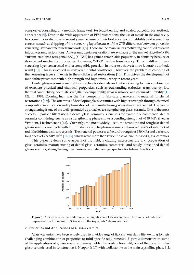
Glass–ceramics have been widely used in a wide range of fields in our daily life, owning to theirchallenging combination of properties to fulfil specific requirements. Figure 2 demonstrates someof the applications of glass–ceramics in many fields. In construction field, one of the most popularglass–ceramic used in construction is Neopariés LT, with wollastonite as the main crystalline phase [1].
Materials 2020, 13, 1049 3 of 22
Neopariés glass–ceramic panels are an ideal alternative to stone for interior and exterior applications.In optical field, many glass–ceramics show high translucency or even can be transparent because of thefact that zero porosity can be relatively easily achieved [16–18]. These make glass–ceramics excellentmaterial for optical applications. For instance, transparent and low thermal expansion glass–ceramicsbased on lithium aluminosilicate (LAS) system have been used as telescope mirror blanks and lasergyroscopes [18]. In military field, glass–ceramics now are used in nosecones of high–performanceaircraft and missiles. Materials used in these applications must exhibit a challenging combination ofproperties to withstand critical conditions resulting from high–speed flying in the atmosphere: Lowcoefficient of thermal expansion; high mechanical strength; high abrasion resistance; high radar wavetransparency for navigation [1,6]. In medical field, bioglass has been successfully used in the medicalfield [12,19]. However, the inherent low strength and low toughness limit the application of bioglassas a load–bearing biomaterial. With crystalline phases as strengthening and toughening phases,glass–ceramics overcome the weakness of bioglass. For instance, A–W glass–ceramic that containsapatite and β–wollastonite (CaO·SiO2) crystals (with the commercial brand name of Cerabone) isconsidered as the most outstanding bioactive glass–ceramics for hard tissue repair [3]. In electronic field,all–solid–state secondary batteries with inorganic solid electrolytes are expected to be next–generationhigh–output batteries. Different types of inorganic solid electrolytes made by glass–ceramics havebeen developed, for instance, Inda et al. [20] showed that glass–ceramics has the crystalline form ofLi1+x+yAlxTi2−xSiyP3−yO12 exhibited a high lithium–ion conductivity of 10−3 S·cm−1. In kitchenwarefield, higher toughness (compared with glass), appealing aesthetics, and very low thermal expansioncoefficient make glass–ceramics the excellent material for kitchenware, such as cooktops, cookware,and bakeware. The most widely used system is the Li2O–Al2O3–SiO2 (LAS) system with additionalcomponents, such as CaO, MgO, ZnO, etc., [1,6]. The main crystalline phase is a β–quartz solid solution,which has an overall negative CTE. LAS glass–ceramics can sustain repeated and quick temperaturechanges of 800 to 1000 ◦C [3,21].
Materials 2019, 12, x FOR PEER REVIEW 3 of 23
the applications of glass–ceramics in many fields. In construction field, one of the most popular glass–
ceramic used in construction is Neopariés LT, with wollastonite as the main crystalline phase [1].
Neopariés glass–ceramic panels are an ideal alternative to stone for interior and exterior applications.
In optical field, many glass–ceramics show high translucency or even can be transparent because of
the fact that zero porosity can be relatively easily achieved [16–18]. These make glass–ceramics
excellent material for optical applications. For instance, transparent and low thermal expansion
glass–ceramics based on lithium aluminosilicate (LAS) system have been used as telescope mirror
blanks and laser gyroscopes [18]. In military field, glass–ceramics now are used in nosecones of high–
performance aircraft and missiles. Materials used in these applications must exhibit a challenging
combination of properties to withstand critical conditions resulting from high–speed flying in the
atmosphere: Low coefficient of thermal expansion; high mechanical strength; high abrasion
resistance; high radar wave transparency for navigation [1,6]. In medical field, bioglass has been
successfully used in the medical field [12,19]. However, the inherent low strength and low toughness
limit the application of bioglass as a load–bearing biomaterial. With crystalline phases as
strengthening and toughening phases, glass–ceramics overcome the weakness of bioglass. For
instance, A–W glass–ceramic that contains apatite and β–wollastonite (CaO∙SiO2) crystals (with the
commercial brand name of Cerabone) is considered as the most outstanding bioactive glass–ceramics
for hard tissue repair [3]. In electronic field, all–solid–state secondary batteries with inorganic solid
electrolytes are expected to be next–generation high–output batteries. Different types of inorganic
solid electrolytes made by glass–ceramics have been developed, for instance, Inda et al. [20] showed
that glass–ceramics has the crystalline form of Li1+x+yAlxTi2−xSiyP3−yO12 exhibited a high lithium–ion
conductivity of 10−3 S∙cm−1. In kitchenware field, higher toughness (compared with glass), appealing
aesthetics, and very low thermal expansion coefficient make glass–ceramics the excellent material for
kitchenware, such as cooktops, cookware, and bakeware. The most widely used system is the Li2O–
Al2O3–SiO2 (LAS) system with additional components, such as CaO, MgO, ZnO, etc., [1,6]. The main
crystalline phase is a β–quartz solid solution, which has an overall negative CTE. LAS glass–ceramics
can sustain repeated and quick temperature changes of 800 to 1000 °C [3,21].
Figure 2. Applications of glass–ceramics in a wide range of fields.
3. Microstructure and Preparation of Glass–Ceramic
3.1. Microstructure Differences between Glass, Glass–Ceramic, and Ceramic
Figure 3 describes the structure differences between glass, glass–ceramics, and ceramic. Strictly
speaking, the term “glass” describes a state of matter where the atoms/molecules are randomly
arranged, in other words, glass materials are amorphous (Figure 3a). Figure 3d shows an example of
a glass in a Li2O–SiO2 system, in which droplets with slightly brighter contrast were embedded in the
Figure 2. Applications of glass–ceramics in a wide range of fields.
3. Microstructure and Preparation of Glass–Ceramic
3.1. Microstructure Differences between Glass, Glass–Ceramic, and Ceramic
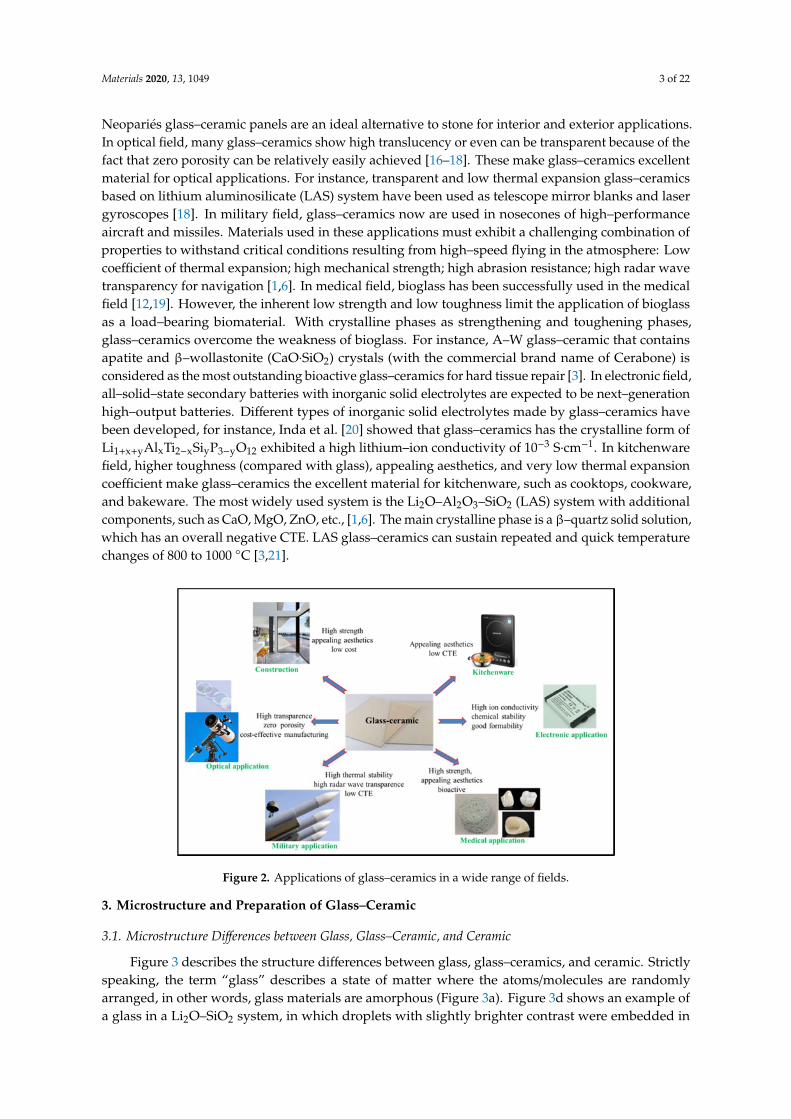
Figure 3 describes the structure differences between glass, glass–ceramics, and ceramic. Strictlyspeaking, the term “glass” describes a state of matter where the atoms/molecules are randomlyarranged, in other words, glass materials are amorphous (Figure 3a). Figure 3d shows an example ofa glass in a Li2O–SiO2 system, in which droplets with slightly brighter contrast were embedded in
Materials 2020, 13, 1049 4 of 22
the glass matrix with darker contrast [22]. Metastable immiscibility that occurs in binary Li2O–SiO2
system causes segregation of the glass phase into droplet–like zones of Li–rich phase and SiO2–richglass matrix [22]. Ceramic materials are mainly composed of crystalline grains, with a small amount ofglass phase at grain boundaries (Figure 3c). Figure 3f reveals the microstructure of zirconia toughenedalumina ceramic; it can be seen that ZrO2 grains (light contrast) and Al2O3 grains (dark contrast) areconnected to each other with grain boundaries [23]. Glass–ceramics are a special group of materialconsisting of at least one crystalline phase and glassy matrix (Figure 3b). Crystalline phase(s) areembedded in the glass matrix. The crystallinity varies most frequently between 30 and 70%. Two typesof interfaces can be found in glass–ceramics; one is the interface between crystalline phases, and theother is the interface between the crystalline phase and the glassy matrix. Figure 3e demonstratesthe microstructure of an LD glass–ceramic. Glass phase has been removed by acid etching, leavingrod–like Li2Si2O5 crystalline phase with a length of 3 to 6 µm.
Materials 2019, 12, x FOR PEER REVIEW 4 of 23
glass matrix with darker contrast [22]. Metastable immiscibility that occurs in binary Li2O–SiO2
system causes segregation of the glass phase into droplet–like zones of Li–rich phase and SiO2–rich
glass matrix [22]. Ceramic materials are mainly composed of crystalline grains, with a small amount
of glass phase at grain boundaries (Figure 3c). Figure 3f reveals the microstructure of zirconia
toughened alumina ceramic; it can be seen that ZrO2 grains (light contrast) and Al2O3 grains (dark
contrast) are connected to each other with grain boundaries [23]. Glass–ceramics are a special group
of material consisting of at least one crystalline phase and glassy matrix (Figure 3b). Crystalline
phase(s) are embedded in the glass matrix. The crystallinity varies most frequently between 30 and
70%. Two types of interfaces can be found in glass–ceramics; one is the interface between crystalline
phases, and the other is the interface between the crystalline phase and the glassy matrix. Figure 3e
demonstrates the microstructure of an LD glass–ceramic. Glass phase has been removed by acid
etching, leaving rod–like Li2Si2O5 crystalline phase with a length of 3 to 6 μm.
Figure 3. Microstructure differences between glass, glass ceramic, and ceramic: schematic
microstructures of glass (a), glass–ceramics (b), and ceramic (c). Corresponding examples of glass (d),
glass–ceramics (e), and ceramic (f). SEM image of non–annealed Li2O–SiO2 glass. Reprinted from ref
[22] with permission. (e) SEM images of lithium disilicate glass–ceramic after etching. (f) SEM image
of zirconia toughened alumina ceramics, with ZrO2 showing light contrast and Al2O3 showing dark
contrast. Reprinted from ref [23] with permission.
3.2. Preparation of Glass–Ceramic
There are two ways to prepare glass–ceramics. Classically, a glass–ceramic is made through
controlled heat treatment of a precursor glass, known as ceramming. Glass–ceramics also can be
produced by concurrent sintering–crystallization of glass–particle compacts. The manufacturing of
glass–ceramic using classic melting–casting–annealing processes involves three general steps [4]
(Figure 4a).
First, preparation of raw materials, glass–forming components, and nucleating agents are mixed
with ball milling [24]. The nucleating agents are used to stimulate nucleation in the following
annealing process; Second, the batch is melted and then cooled to room temperature to form a
precursor glass. A homogeneous molten glass is formed by heating the raw materials to elevated
temperature in a high–temperature furnace. The melt is then casted into a mold with the desired
shape. After cooling to room temperature, a precursor glass forms.
Figure 3. Microstructure differences between glass, glass ceramic, and ceramic: schematicmicrostructures of glass (a), glass–ceramics (b), and ceramic (c). Corresponding examples of glass (d),glass–ceramics (e), and ceramic (f). SEM image of non–annealed Li2O–SiO2 glass. Reprinted fromref [22] with permission. (e) SEM images of lithium disilicate glass–ceramic after etching. (f) SEMimage of zirconia toughened alumina ceramics, with ZrO2 showing light contrast and Al2O3 showingdark contrast. Reprinted from ref [23] with permission.
3.2. Preparation of Glass–Ceramic
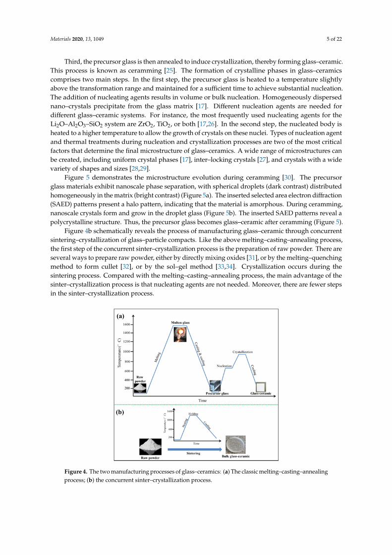
There are two ways to prepare glass–ceramics. Classically, a glass–ceramic is made throughcontrolled heat treatment of a precursor glass, known as ceramming. Glass–ceramics also can beproduced by concurrent sintering–crystallization of glass–particle compacts. The manufacturingof glass–ceramic using classic melting–casting–annealing processes involves three general steps [4](Figure 4a).
First, preparation of raw materials, glass–forming components, and nucleating agents are mixedwith ball milling [24]. The nucleating agents are used to stimulate nucleation in the following annealingprocess; Second, the batch is melted and then cooled to room temperature to form a precursor glass.A homogeneous molten glass is formed by heating the raw materials to elevated temperature in ahigh–temperature furnace. The melt is then casted into a mold with the desired shape. After cooling toroom temperature, a precursor glass forms.
Materials 2020, 13, 1049 5 of 22
Third, the precursor glass is then annealed to induce crystallization, thereby forming glass–ceramic.This process is known as ceramming [25]. The formation of crystalline phases in glass–ceramicscomprises two main steps. In the first step, the precursor glass is heated to a temperature slightlyabove the transformation range and maintained for a sufficient time to achieve substantial nucleation.The addition of nucleating agents results in volume or bulk nucleation. Homogeneously dispersednano–crystals precipitate from the glass matrix [17]. Different nucleation agents are needed fordifferent glass–ceramic systems. For instance, the most frequently used nucleating agents for theLi2O–Al2O3–SiO2 system are ZrO2, TiO2, or both [17,26]. In the second step, the nucleated body isheated to a higher temperature to allow the growth of crystals on these nuclei. Types of nucleation agentand thermal treatments during nucleation and crystallization processes are two of the most criticalfactors that determine the final microstructure of glass–ceramics. A wide range of microstructures canbe created, including uniform crystal phases [17], inter–locking crystals [27], and crystals with a widevariety of shapes and sizes [28,29].
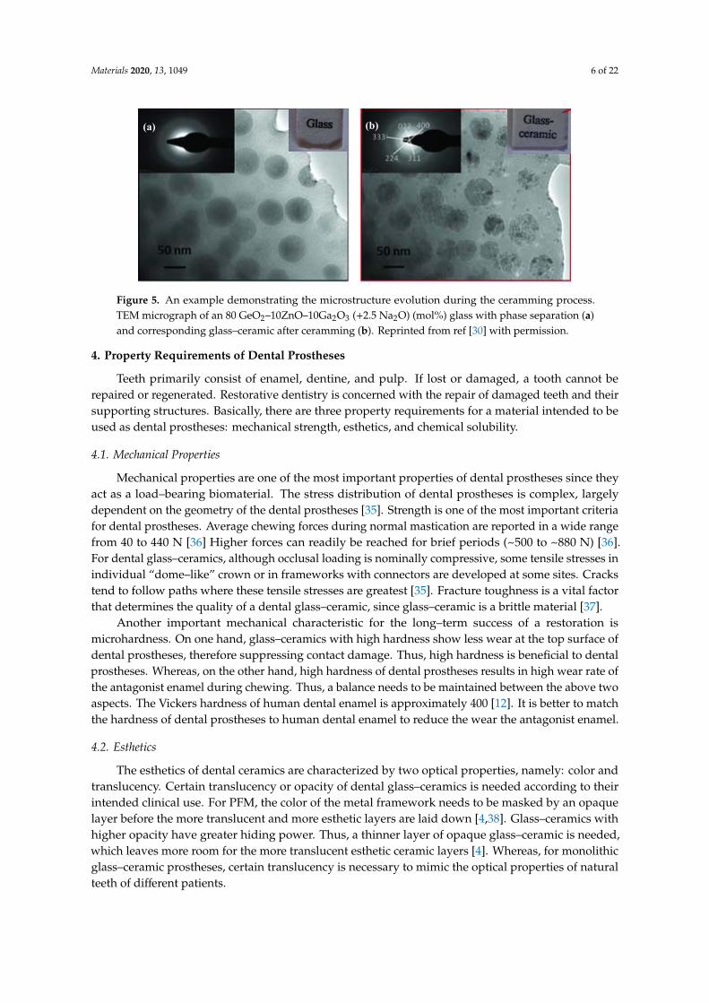
Figure 5 demonstrates the microstructure evolution during ceramming [30]. The precursorglass materials exhibit nanoscale phase separation, with spherical droplets (dark contrast) distributedhomogeneously in the matrix (bright contrast) (Figure 5a). The inserted selected area electron diffraction(SAED) patterns present a halo pattern, indicating that the material is amorphous. During ceramming,nanoscale crystals form and grow in the droplet glass (Figure 5b). The inserted SAED patterns reveal apolycrystalline structure. Thus, the precursor glass becomes glass–ceramic after ceramming (Figure 5).
Figure 4b schematically reveals the process of manufacturing glass–ceramic through concurrentsintering–crystallization of glass–particle compacts. Like the above melting–casting–annealing process,the first step of the concurrent sinter–crystallization process is the preparation of raw powder. There areseveral ways to prepare raw powder, either by directly mixing oxides [31], or by the melting–quenchingmethod to form cullet [32], or by the sol–gel method [33,34]. Crystallization occurs during thesintering process. Compared with the melting–casting–annealing process, the main advantage of thesinter–crystallization process is that nucleating agents are not needed. Moreover, there are fewer stepsin the sinter–crystallization process.
Materials 2019, 12, x FOR PEER REVIEW 5 of 23
Third, the precursor glass is then annealed to induce crystallization, thereby forming glass–
ceramic. This process is known as ceramming [25]. The formation of crystalline phases in glass–
ceramics comprises two main steps. In the first step, the precursor glass is heated to a temperature
slightly above the transformation range and maintained for a sufficient time to achieve substantial
nucleation. The addition of nucleating agents results in volume or bulk nucleation. Homogeneously
dispersed nano–crystals precipitate from the glass matrix [17]. Different nucleation agents are needed
for different glass–ceramic systems. For instance, the most frequently used nucleating agents for the
Li2O–Al2O3–SiO2 system are ZrO2, TiO2, or both [17,26]. In the second step, the nucleated body is
heated to a higher temperature to allow the growth of crystals on these nuclei. Types of nucleation
agent and thermal treatments during nucleation and crystallization processes are two of the most
critical factors that determine the final microstructure of glass–ceramics. A wide range of
microstructures can be created, including uniform crystal phases [17], inter–locking crystals [27], and
crystals with a wide variety of shapes and sizes [28,29].
Figure 5 demonstrates the microstructure evolution during ceramming [30]. The precursor glass
materials exhibit nanoscale phase separation, with spherical droplets (dark contrast) distributed
homogeneously in the matrix (bright contrast) (Figure 5a). The inserted selected area electron
diffraction (SAED) patterns present a halo pattern, indicating that the material is amorphous. During
ceramming, nanoscale crystals form and grow in the droplet glass (Figure 5b). The inserted SAED
patterns reveal a polycrystalline structure. Thus, the precursor glass becomes glass–ceramic after
ceramming (Figure 5).
Figure 4b schematically reveals the process of manufacturing glass–ceramic through concurrent
sintering–crystallization of glass–particle compacts. Like the above melting–casting–annealing
process, the first step of the concurrent sinter–crystallization process is the preparation of raw
powder. There are several ways to prepare raw powder, either by directly mixing oxides [31], or by
the melting–quenching method to form cullet [32], or by the sol–gel method [33,34]. Crystallization
occurs during the sintering process. Compared with the melting–casting–annealing process, the main
advantage of the sinter–crystallization process is that nucleating agents are not needed. Moreover,
there are fewer steps in the sinter–crystallization process.
Figure 4. The two manufacturing processes of glass–ceramics: (a) The classic melting–casting–
annealing process; (b) the concurrent sinter–crystallization process.
(a)
(b)
Figure 4. The two manufacturing processes of glass–ceramics: (a) The classic melting–casting–annealingprocess; (b) the concurrent sinter–crystallization process.
Materials 2020, 13, 1049 6 of 22
Materials 2019, 12, x FOR PEER REVIEW 6 of 23
Figure 5. An example demonstrating the microstructure evolution during the ceramming process.
TEM micrograph of an 80 GeO2–10ZnO–10Ga2O3 (+2.5 Na2O) (mol%) glass with phase separation (a)
and corresponding glass–ceramic after ceramming (b). Reprinted from ref [30] with permission.
4. Property Requirements of Dental Prostheses
Teeth primarily consist of enamel, dentine, and pulp. If lost or damaged, a tooth cannot be
repaired or regenerated. Restorative dentistry is concerned with the repair of damaged teeth and
their supporting structures. Basically, there are three property requirements for a material intended
to be used as dental prostheses: mechanical strength, esthetics, and chemical solubility.
4.1. Mechanical Properties
Mechanical properties are one of the most important properties of dental prostheses since they
act as a load–bearing biomaterial. The stress distribution of dental prostheses is complex, largely
dependent on the geometry of the dental prostheses [35]. Strength is one of the most important
criteria for dental prostheses. Average chewing forces during normal mastication are reported in a
wide range from 40 to 440 N [36] Higher forces can readily be reached for brief periods (~500 to ~880
N) [36]. For dental glass–ceramics, although occlusal loading is nominally compressive, some tensile
stresses in individual “dome–like” crown or in frameworks with connectors are developed at some
sites. Cracks tend to follow paths where these tensile stresses are greatest [35]. Fracture toughness is
a vital factor that determines the quality of a dental glass–ceramic, since glass–ceramic is a brittle
material [37].
Another important mechanical characteristic for the long–term success of a restoration is
microhardness. On one hand, glass–ceramics with high hardness show less wear at the top surface of
dental prostheses, therefore suppressing contact damage. Thus, high hardness is beneficial to dental
prostheses. Whereas, on the other hand, high hardness of dental prostheses results in high wear rate
of the antagonist enamel during chewing. Thus, a balance needs to be maintained between the above
two aspects. The Vickers hardness of human dental enamel is approximately 400 [12]. It is better to
match the hardness of dental prostheses to human dental enamel to reduce the wear the antagonist
enamel.
4.2. Esthetics
The esthetics of dental ceramics are characterized by two optical properties, namely: color and
translucency. Certain translucency or opacity of dental glass–ceramics is needed according to their
intended clinical use. For PFM, the color of the metal framework needs to be masked by an opaque
layer before the more translucent and more esthetic layers are laid down [4,38]. Glass–ceramics with
higher opacity have greater hiding power. Thus, a thinner layer of opaque glass–ceramic is needed,
which leaves more room for the more translucent esthetic ceramic layers [4]. Whereas, for monolithic
glass–ceramic prostheses, certain translucency is necessary to mimic the optical properties of natural
teeth of different patients.
(a) (b)
Figure 5. An example demonstrating the microstructure evolution during the ceramming process.TEM micrograph of an 80 GeO2–10ZnO–10Ga2O3 (+2.5 Na2O) (mol%) glass with phase separation (a)and corresponding glass–ceramic after ceramming (b). Reprinted from ref [30] with permission.
4. Property Requirements of Dental Prostheses
Teeth primarily consist of enamel, dentine, and pulp. If lost or damaged, a tooth cannot berepaired or regenerated. Restorative dentistry is concerned with the repair of damaged teeth and theirsupporting structures. Basically, there are three property requirements for a material intended to beused as dental prostheses: mechanical strength, esthetics, and chemical solubility.
4.1. Mechanical Properties
Mechanical properties are one of the most important properties of dental prostheses since theyact as a load–bearing biomaterial. The stress distribution of dental prostheses is complex, largelydependent on the geometry of the dental prostheses [35]. Strength is one of the most important criteriafor dental prostheses. Average chewing forces during normal mastication are reported in a wide rangefrom 40 to 440 N [36] Higher forces can readily be reached for brief periods (~500 to ~880 N) [36].For dental glass–ceramics, although occlusal loading is nominally compressive, some tensile stresses inindividual “dome–like” crown or in frameworks with connectors are developed at some sites. Crackstend to follow paths where these tensile stresses are greatest [35]. Fracture toughness is a vital factorthat determines the quality of a dental glass–ceramic, since glass–ceramic is a brittle material [37].
Another important mechanical characteristic for the long–term success of a restoration ismicrohardness. On one hand, glass–ceramics with high hardness show less wear at the top surface ofdental prostheses, therefore suppressing contact damage. Thus, high hardness is beneficial to dentalprostheses. Whereas, on the other hand, high hardness of dental prostheses results in high wear rate ofthe antagonist enamel during chewing. Thus, a balance needs to be maintained between the above twoaspects. The Vickers hardness of human dental enamel is approximately 400 [12]. It is better to matchthe hardness of dental prostheses to human dental enamel to reduce the wear the antagonist enamel.
4.2. Esthetics
The esthetics of dental ceramics are characterized by two optical properties, namely: color andtranslucency. Certain translucency or opacity of dental glass–ceramics is needed according to theirintended clinical use. For PFM, the color of the metal framework needs to be masked by an opaquelayer before the more translucent and more esthetic layers are laid down [4,38]. Glass–ceramics withhigher opacity have greater hiding power. Thus, a thinner layer of opaque glass–ceramic is needed,which leaves more room for the more translucent esthetic ceramic layers [4]. Whereas, for monolithicglass–ceramic prostheses, certain translucency is necessary to mimic the optical properties of naturalteeth of different patients.
Materials 2020, 13, 1049 7 of 22
4.3. Chemical Resistance
Dental glass–ceramics are biomaterials that need to stay in the human oral cavity body for a longtime (more than 10 years). Thus, for glass–ceramics to survive not only do they need to be strongand tough enough to resist the biting forces (as discussed above), they also have to be able to resistthe acidic/alkaline corrosive environment in the oral cavity at approximately 37 ◦C [39]. Accordingto international standard ISO 6872 [40], dental glass–ceramics intended for different clinic uses havedifferent chemical solubility requirements. For instance, the chemical solubility of monolithic ceramicfor single–unit anterior prostheses, veneers, inlays, or onlays must be less than 100 µg/cm3 [40].In comparison, partially or fully covered substructure ceramic for single–unit anterior or posteriorprostheses should have a chemical solubility of less than 2000 µg/cm3 [40].
5. Manufacturing of Dental Restorations
Dental restorations can be fabricated by different methods: powder condensation(conventional powder slurry ceramics/glass–ceramics), lost–wax/heat pressed technique (pressableceramics/glass–ceramics), slip casting (infiltrated ceramics), and CAD/CAM (computer–aideddesign and computer–aided manufacturing) technique (machinable ceramics/glass–ceramics) [41].The CAD/CAM technique is selected to be discussed in detail since the technique is currently the mostwidely used manufacturing technique. Additive manufacturing (AM), as a developing and promisingtechnique, has received much attention in dentistry. This is a future–oriented technique. Thus, whathas been achieved so far and problems need to be solved in the future related to AM in dentistry willalso be discussed.
5.1. CAD–CAM Workflow
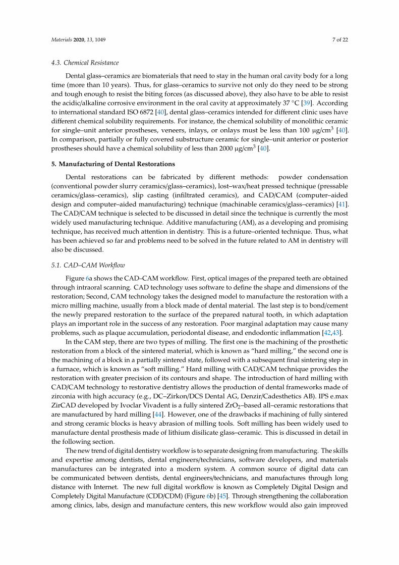
Figure 6a shows the CAD–CAM workflow. First, optical images of the prepared teeth are obtainedthrough intraoral scanning. CAD technology uses software to define the shape and dimensions of therestoration; Second, CAM technology takes the designed model to manufacture the restoration with amicro milling machine, usually from a block made of dental material. The last step is to bond/cementthe newly prepared restoration to the surface of the prepared natural tooth, in which adaptationplays an important role in the success of any restoration. Poor marginal adaptation may cause manyproblems, such as plaque accumulation, periodontal disease, and endodontic inflammation [42,43].
In the CAM step, there are two types of milling. The first one is the machining of the prostheticrestoration from a block of the sintered material, which is known as “hard milling,” the second one isthe machining of a block in a partially sintered state, followed with a subsequent final sintering step ina furnace, which is known as “soft milling.” Hard milling with CAD/CAM technique provides therestoration with greater precision of its contours and shape. The introduction of hard milling withCAD/CAM technology to restorative dentistry allows the production of dental frameworks made ofzirconia with high accuracy (e.g., DC–Zirkon/DCS Dental AG, Denzir/Cadesthetics AB). IPS e.maxZirCAD developed by Ivoclar Vivadent is a fully sintered ZrO2–based all–ceramic restorations thatare manufactured by hard milling [44]. However, one of the drawbacks if machining of fully sinteredand strong ceramic blocks is heavy abrasion of milling tools. Soft milling has been widely used tomanufacture dental prosthesis made of lithium disilicate glass–ceramic. This is discussed in detail inthe following section.
The new trend of digital dentistry workflow is to separate designing from manufacturing. The skillsand expertise among dentists, dental engineers/technicians, software developers, and materialsmanufactures can be integrated into a modern system. A common source of digital data canbe communicated between dentists, dental engineers/technicians, and manufactures through longdistance with Internet. The new full digital workflow is known as Completely Digital Design andCompletely Digital Manufacture (CDD/CDM) (Figure 6b) [45]. Through strengthening the collaborationamong clinics, labs, design and manufacture centers, this new workflow would also gain improved
Materials 2020, 13, 1049 8 of 22
efficiency/accuracy/reliability, as well as the predictable and visualized results for meeting the patientsatisfaction. More detail information about the novel cloud connected dental system can be foundin ref [45].
Materials 2019, 12, x FOR PEER REVIEW 8 of 23
meeting the patient satisfaction. More detail information about the novel cloud connected dental
system can be found in ref [45].
Figure 6. Computer–aided design and computer–aided manufacturing (CAD–CAM)–based
workflow in dentistry. (a) The Cerec workflow includes three steps: first, a intraoral canner is used to
acquire optical images of the prepared teeth; second, raw scanning data is processed with the aid of
the chairside software, followed by the design of the restoration; third, CAM technology takes the
designed model to a computer numeric control machine to manufacture the restoration. (b) The novel
cloud connected digital dentistry system. The full worldwide digital platform is characterized by the
separation of design work to form independent design centers from the convention production
centers. Reprinted from [45].
5.2. Additive Manufacturing (AM) Technique
Although the CAD–CAM technique has already been well established in dentistry [46], the
major drawback of this technique is the great waste of material upon machining since it is a
subtractive manufacturing method. The waste corresponds to approximately 90% of the
prefabricated block in some cases and leftovers from these are not reusable. AM technique, also
known as 3D printing, could be an effective new technology to overcome this problem. Meanwhile,
the rising demand for custom–tailored and patient specific dental products renders dentistry to be
one of the rapidly expanding segments of AM [47]. AM involves processing methodologies that are
capable of producing structures by depositing materials layer–by–layer resorting to a computer–
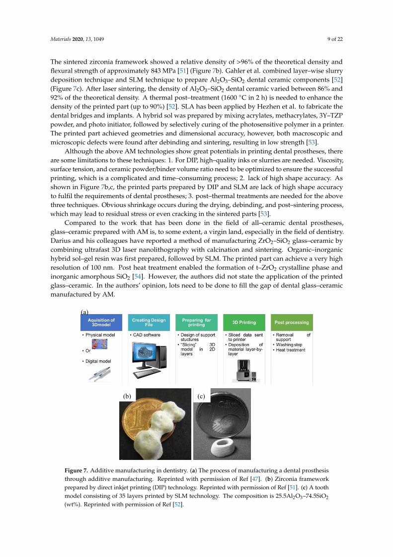
generated design file (STL) [47–49]. Figure 7a briefly shows the process of manufacturing a dental
prosthesis with AM technique. Similar to CAD/CAM technique, raw data is first acquired through
intraoral scanning, followed by the building of 3D digital model with the aid of CAD software;
second, an STL is constructed with the 3D digital model and transformed to 3D printing machine;
third, each material layer is deposited one on top of the other within the 3D machine, consecutively,
forming a three–dimensional part; fourth, some post–processing steps are needed to obtain the final
dental prostheses, such as removal support, washing, and heat treatment [47].
Numerous AM techniques can be utilized to manufacture dental prostheses, including direct
inkjet printing (DIP), selective laser melting (SLM), stereolithography (SLA), etc., [47,50]. DIP has
been used by Özkol and his colleagues to prepare zirconia dental prostheses [51]. A tailored zirconia–
(a)
(b)
Figure 6. Computer–aided design and computer–aided manufacturing (CAD–CAM)–based workflowin dentistry. (a) The Cerec workflow includes three steps: first, a intraoral canner is used to acquire opticalimages of the prepared teeth; second, raw scanning data is processed with the aid of the chairside software,followed by the design of the restoration; third, CAM technology takes the designed model to a computernumeric control machine to manufacture the restoration. (b) The novel cloud connected digital dentistrysystem. The full worldwide digital platform is characterized by the separation of design work to formindependent design centers from the convention production centers. Reprinted from [45].
5.2. Additive Manufacturing (AM) Technique
Although the CAD–CAM technique has already been well established in dentistry [46], the majordrawback of this technique is the great waste of material upon machining since it is a subtractivemanufacturing method. The waste corresponds to approximately 90% of the prefabricated block in somecases and leftovers from these are not reusable. AM technique, also known as 3D printing, could be aneffective new technology to overcome this problem. Meanwhile, the rising demand for custom–tailoredand patient specific dental products renders dentistry to be one of the rapidly expanding segments ofAM [47]. AM involves processing methodologies that are capable of producing structures by depositingmaterials layer–by–layer resorting to a computer–generated design file (STL) [47–49]. Figure 7a brieflyshows the process of manufacturing a dental prosthesis with AM technique. Similar to CAD/CAMtechnique, raw data is first acquired through intraoral scanning, followed by the building of 3D digitalmodel with the aid of CAD software; second, an STL is constructed with the 3D digital model andtransformed to 3D printing machine; third, each material layer is deposited one on top of the other withinthe 3D machine, consecutively, forming a three–dimensional part; fourth, some post–processing steps areneeded to obtain the final dental prostheses, such as removal support, washing, and heat treatment [47].
Numerous AM techniques can be utilized to manufacture dental prostheses, including directinkjet printing (DIP), selective laser melting (SLM), stereolithography (SLA), etc., [47,50]. DIP has beenused by Özkol and his colleagues to prepare zirconia dental prostheses [51]. A tailored zirconia–basedceramic suspension was printed on a inkjet printer, followed by drying, debinding, and sintering.
Materials 2020, 13, 1049 9 of 22
The sintered zirconia framework showed a relative density of >96% of the theoretical density andflexural strength of approximately 843 MPa [51] (Figure 7b). Gahler et al. combined layer–wise slurrydeposition technique and SLM technique to prepare Al2O3–SiO2 dental ceramic components [52](Figure 7c). After laser sintering, the density of Al2O3–SiO2 dental ceramic varied between 86% and92% of the theoretical density. A thermal post–treatment (1600 ◦C in 2 h) is needed to enhance thedensity of the printed part (up to 90%) [52]. SLA has been applied by Hezhen et al. to fabricate thedental bridges and implants. A hybrid sol was prepared by mixing acrylates, methacrylates, 3Y–TZPpowder, and photo initiator, followed by selectively curing of the photosensitive polymer in a printer.The printed part achieved geometries and dimensional accuracy, however, both macroscopic andmicroscopic defects were found after debinding and sintering, resulting in low strength [53].
Although the above AM technologies show great potentials in printing dental prostheses, thereare some limitations to these techniques: 1. For DIP, high–quality inks or slurries are needed. Viscosity,surface tension, and ceramic powder/binder volume ratio need to be optimized to ensure the successfulprinting, which is a complicated and time–consuming process; 2. lack of high shape accuracy. Asshown in Figure 7b,c, the printed parts prepared by DIP and SLM are lack of high shape accuracyto fulfil the requirements of dental prostheses; 3. post–thermal treatments are needed for the abovethree techniques. Obvious shrinkage occurs during the drying, debinding, and post–sintering process,which may lead to residual stress or even cracking in the sintered parts [53].
Compared to the work that has been done in the field of all–ceramic dental prostheses,glass–ceramic prepared with AM is, to some extent, a virgin land, especially in the field of dentistry.Darius and his colleagues have reported a method of manufacturing ZrO2–SiO2 glass–ceramic bycombining ultrafast 3D laser nanolithography with calcination and sintering. Organic–inorganichybrid sol–gel resin was first prepared, followed by SLM. The printed part can achieve a very highresolution of 100 nm. Post heat treatment enabled the formation of t–ZrO2 crystalline phase andinorganic amorphous SiO2 [54]. However, the authors did not state the application of the printedglass–ceramic. In the authors’ opinion, lots need to be done to fill the gap of dental glass–ceramicmanufactured by AM.
Materials 2019, 12, x FOR PEER REVIEW 9 of 23
based ceramic suspension was printed on a inkjet printer, followed by drying, debinding, and
sintering. The sintered zirconia framework showed a relative density of >96% of the theoretical
density and flexural strength of approximately 843 MPa [51] (Figure 7b). Gahler et al. combined
layer–wise slurry deposition technique and SLM technique to prepare Al2O3–SiO2 dental ceramic
components [52] (Figure 7c). After laser sintering, the density of Al2O3–SiO2 dental ceramic varied
between 86% and 92% of the theoretical density. A thermal post–treatment (1600 °C in 2 h) is needed
to enhance the density of the printed part (up to 90%) [52]. SLA has been applied by Hezhen et al. to
fabricate the dental bridges and implants. A hybrid sol was prepared by mixing acrylates,
methacrylates, 3Y–TZP powder, and photo initiator, followed by selectively curing of the
photosensitive polymer in a printer. The printed part achieved geometries and dimensional accuracy,
however, both macroscopic and microscopic defects were found after debinding and sintering,
resulting in low strength [53].
Although the above AM technologies show great potentials in printing dental prostheses, there
are some limitations to these techniques: 1. For DIP, high–quality inks or slurries are needed.
Viscosity, surface tension, and ceramic powder/binder volume ratio need to be optimized to ensure
the successful printing, which is a complicated and time–consuming process; 2. lack of high shape
accuracy. As shown in Figure 7b,c, the printed parts prepared by DIP and SLM are lack of high shape
accuracy to fulfil the requirements of dental prostheses; 3. post–thermal treatments are needed for
the above three techniques. Obvious shrinkage occurs during the drying, debinding, and post–
sintering process, which may lead to residual stress or even cracking in the sintered parts [53].
Compared to the work that has been done in the field of all–ceramic dental prostheses, glass–
ceramic prepared with AM is, to some extent, a virgin land, especially in the field of dentistry. Darius
and his colleagues have reported a method of manufacturing ZrO2–SiO2 glass–ceramic by combining
ultrafast 3D laser nanolithography with calcination and sintering. Organic–inorganic hybrid sol–gel
resin was first prepared, followed by SLM. The printed part can achieve a very high resolution of 100
nm. Post heat treatment enabled the formation of t–ZrO2 crystalline phase and inorganic amorphous
SiO2 [54]. However, the authors did not state the application of the printed glass–ceramic. In the
authors’ opinion, lots need to be done to fill the gap of dental glass–ceramic manufactured by AM.
Figure 7. Additive manufacturing in dentistry. (a) The process of manufacturing a dental prosthesis
through additive manufacturing. Reprinted with permission of Ref [47]. (b) Zirconia framework
prepared by direct inkjet printing (DIP) technology. Reprinted with permission of Ref [51]. (c) A tooth
(a)
(b) (c)
Figure 7. Additive manufacturing in dentistry. (a) The process of manufacturing a dental prosthesisthrough additive manufacturing. Reprinted with permission of Ref [47]. (b) Zirconia frameworkprepared by direct inkjet printing (DIP) technology. Reprinted with permission of Ref [51]. (c) A toothmodel consisting of 35 layers printed by SLM technology. The composition is 25.5Al2O3–74.5SiO2
(wt%). Reprinted with permission of Ref [52].
Materials 2020, 13, 1049 10 of 22
6. Commercially Available and Newly–Developed Dental Glass–Ceramics
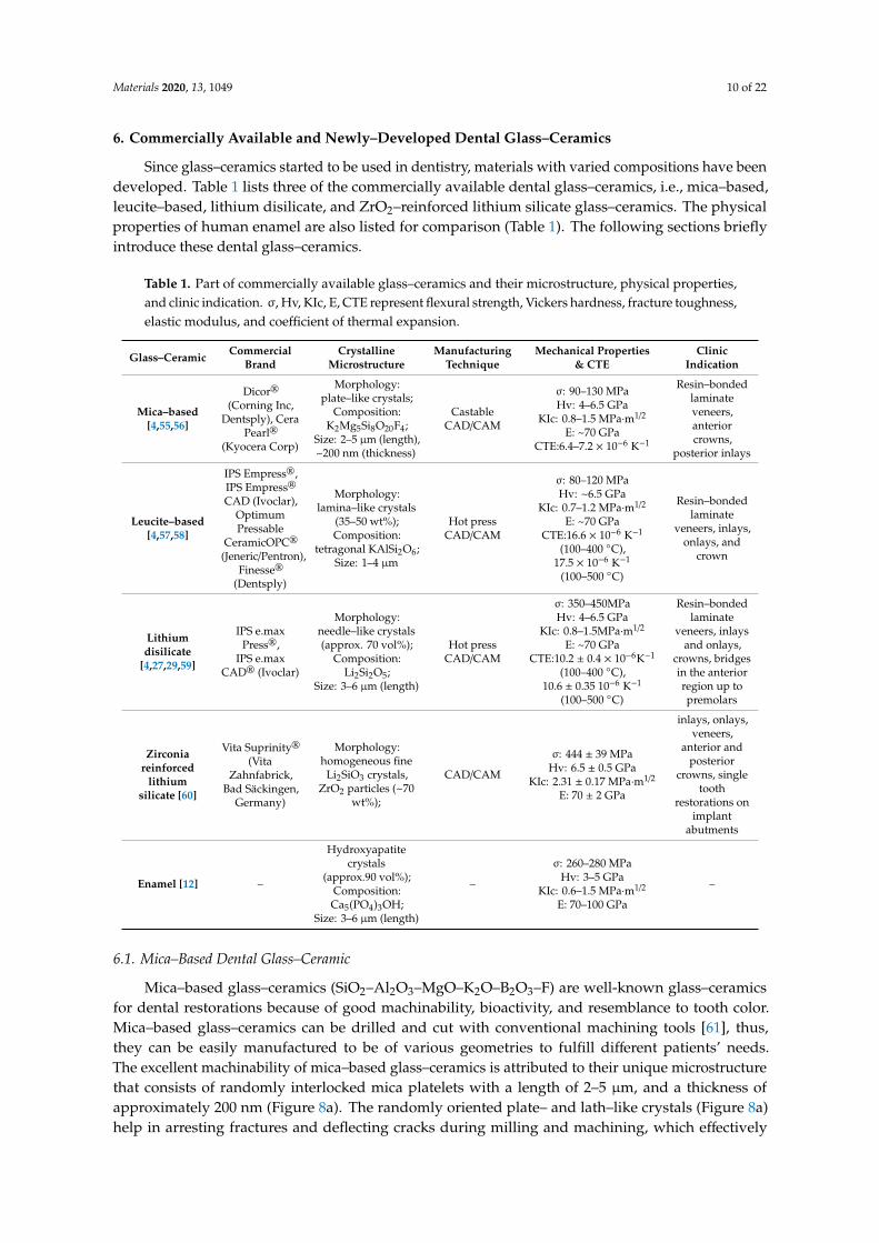
Since glass–ceramics started to be used in dentistry, materials with varied compositions have beendeveloped. Table 1 lists three of the commercially available dental glass–ceramics, i.e., mica–based,leucite–based, lithium disilicate, and ZrO2–reinforced lithium silicate glass–ceramics. The physicalproperties of human enamel are also listed for comparison (Table 1). The following sections brieflyintroduce these dental glass–ceramics.
Table 1. Part of commercially available glass–ceramics and their microstructure, physical properties,and clinic indication. σ, Hv, KIc, E, CTE represent flexural strength, Vickers hardness, fracture toughness,elastic modulus, and coefficient of thermal expansion.
Glass–Ceramic CommercialBrand
CrystallineMicrostructure
ManufacturingTechnique
Mechanical Properties& CTE
ClinicIndication
Mica–based[4,55,56]
Dicor®
(Corning Inc,Dentsply), Cera
Pearl®
(Kyocera Corp)
Morphology:plate–like crystals;
Composition:K2Mg5Si8O20F4;
Size: 2–5 µm (length),~200 nm (thickness)
CastableCAD/CAM
σ: 90–130 MPaHv: 4–6.5 GPa
KIc: 0.8–1.5 MPa·m1/2
E: ~70 GPaCTE:6.4–7.2 × 10⁻⁶ K−1
Resin–bondedlaminateveneers,anteriorcrowns,
posterior inlays
Leucite–based[4,57,58]
IPS Empress®,IPS Empress®
CAD (Ivoclar),OptimumPressable
CeramicOPC®
(Jeneric/Pentron),Finesse®
(Dentsply)
Morphology:lamina–like crystals
(35–50 wt%);Composition:
tetragonal KAlSi2O6;Size: 1–4 µm
Hot pressCAD/CAM
σ: 80–120 MPaHv: ~6.5 GPa
KIc: 0.7–1.2 MPa·m1/2
E: ~70 GPaCTE:16.6 × 10⁻⁶ K−1
(100–400 ◦C),17.5 × 10−6 K−1
(100–500 ◦C)
Resin–bondedlaminate
veneers, inlays,onlays, and
crown
Lithiumdisilicate
[4,27,29,59]
IPS e.maxPress®,
IPS e.maxCAD® (Ivoclar)
Morphology:needle–like crystals(approx. 70 vol%);
Composition:Li2Si2O5;
Size: 3–6 µm (length)
Hot pressCAD/CAM
σ: 350–450MPaHv: 4–6.5 GPa
KIc: 0.8–1.5MPa·m1/2
E: ~70 GPaCTE:10.2 ± 0.4 × 10⁻⁶K−1
(100–400 ◦C),10.6 ± 0.35 10−6 K−1
(100–500 ◦C)
Resin–bondedlaminate
veneers, inlaysand onlays,
crowns, bridgesin the anteriorregion up topremolars
Zirconiareinforced
lithiumsilicate [60]
Vita Suprinity®
(VitaZahnfabrick,
Bad Säckingen,Germany)
Morphology:homogeneous fine
Li2SiO3 crystals,ZrO2 particles (~70
wt%);
CAD/CAM
σ: 444 ± 39 MPaHv: 6.5 ± 0.5 GPa
KIc: 2.31 ± 0.17 MPa·m1/2
E: 70 ± 2 GPa
inlays, onlays,veneers,
anterior andposterior
crowns, singletooth
restorations onimplant
abutments
Enamel [12] –
Hydroxyapatitecrystals
(approx.90 vol%);Composition:Ca5(PO4)3OH;
Size: 3–6 µm (length)
–
σ: 260–280 MPaHv: 3–5 GPa
KIc: 0.6–1.5 MPa·m1/2
E: 70–100 GPa
–
6.1. Mica–Based Dental Glass–Ceramic
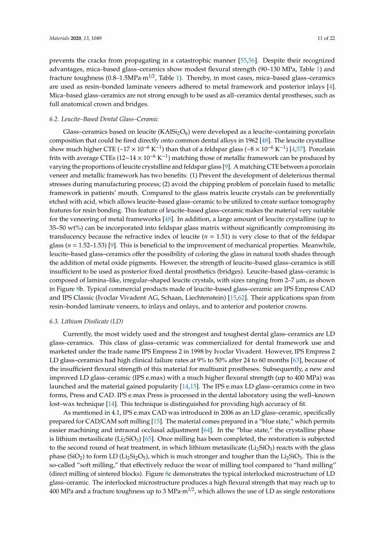
Mica–based glass–ceramics (SiO2–Al2O3–MgO–K2O–B2O3–F) are well-known glass–ceramicsfor dental restorations because of good machinability, bioactivity, and resemblance to tooth color.Mica–based glass–ceramics can be drilled and cut with conventional machining tools [61], thus,they can be easily manufactured to be of various geometries to fulfill different patients’ needs.The excellent machinability of mica–based glass–ceramics is attributed to their unique microstructurethat consists of randomly interlocked mica platelets with a length of 2–5 µm, and a thickness ofapproximately 200 nm (Figure 8a). The randomly oriented plate– and lath–like crystals (Figure 8a)help in arresting fractures and deflecting cracks during milling and machining, which effectively
Materials 2020, 13, 1049 11 of 22
prevents the cracks from propagating in a catastrophic manner [55,56]. Despite their recognizedadvantages, mica–based glass–ceramics show modest flexural strength (90–130 MPa, Table 1) andfracture toughness (0.8–1.5MPa·m1/2, Table 1). Thereby, in most cases, mica–based glass–ceramicsare used as resin–bonded laminate veneers adhered to metal framework and posterior inlays [4].Mica–based glass–ceramics are not strong enough to be used as all–ceramics dental prostheses, such asfull anatomical crown and bridges.
6.2. Leucite–Based Dental Glass–Ceramic
Glass–ceramics based on leucite (KAlSi2O6) were developed as a leucite–containing porcelaincomposition that could be fired directly onto common dental alloys in 1962 [48]. The leucite crystallineshow much higher CTE (~17 × 10−6 K−1) than that of a feldspar glass (~8 × 10⁻⁶ K−1) [4,57]. Porcelainfrits with average CTEs (12−14 × 10−6 K−1) matching those of metallic framework can be produced byvarying the proportions of leucite crystalline and feldspar glass [9]. A matching CTE between a porcelainveneer and metallic framework has two benefits: (1) Prevent the development of deleterious thermalstresses during manufacturing process; (2) avoid the chipping problem of porcelain fused to metallicframework in patients’ mouth. Compared to the glass matrix leucite crystals can be preferentiallyetched with acid, which allows leucite–based glass–ceramic to be utilized to create surface tomographyfeatures for resin bonding. This feature of leucite–based glass–ceramic makes the material very suitablefor the veneering of metal frameworks [48]. In addition, a large amount of leucite crystalline (up to35–50 wt%) can be incorporated into feldspar glass matrix without significantly compromising itstranslucency because the refractive index of leucite (n = 1.51) is very close to that of the feldsparglass (n = 1.52–1.53) [9]. This is beneficial to the improvement of mechanical properties. Meanwhile,leucite–based glass–ceramics offer the possibility of coloring the glass in natural tooth shades throughthe addition of metal oxide pigments. However, the strength of leucite–based glass–ceramics is stillinsufficient to be used as posterior fixed dental prosthetics (bridges). Leucite–based glass–ceramic iscomposed of lamina–like, irregular–shaped leucite crystals, with sizes ranging from 2–7 µm, as shownin Figure 8b. Typical commercial products made of leucite–based glass–ceramic are IPS Empress CADand IPS Classic (Ivoclar Vivadent AG, Schaan, Liechtenstein) [15,62]. Their applications span fromresin–bonded laminate veneers, to inlays and onlays, and to anterior and posterior crowns.
6.3. Lithium Disilicate (LD)
Currently, the most widely used and the strongest and toughest dental glass–ceramics are LDglass–ceramics. This class of glass–ceramic was commercialized for dental framework use andmarketed under the trade name IPS Empress 2 in 1998 by Ivoclar Vivadent. However, IPS Empress 2LD glass–ceramics had high clinical failure rates at 9% to 50% after 24 to 60 months [63], because ofthe insufficient flexural strength of this material for multiunit prostheses. Subsequently, a new andimproved LD glass–ceramic (IPS e.max) with a much higher flexural strength (up to 400 MPa) waslaunched and the material gained popularity [14,15]. The IPS e.max LD glass–ceramics come in twoforms, Press and CAD. IPS e.max Press is processed in the dental laboratory using the well–knownlost–wax technique [14]. This technique is distinguished for providing high accuracy of fit.
As mentioned in 4.1, IPS e.max CAD was introduced in 2006 as an LD glass–ceramic, specificallyprepared for CAD/CAM soft milling [15]. The material comes prepared in a “blue state,” which permitseasier machining and intraoral occlusal adjustment [64]. In the “blue state,” the crystalline phaseis lithium metasilicate (Li2SiO3) [65]. Once milling has been completed, the restoration is subjectedto the second round of heat treatment, in which lithium metasilicate (Li2SiO3) reacts with the glassphase (SiO2) to form LD (Li2Si2O5), which is much stronger and tougher than the Li2SiO3. This is theso-called “soft milling,” that effectively reduce the wear of milling tool compared to “hard milling”(direct milling of sintered blocks). Figure 8c demonstrates the typical interlocked microstructure of LDglass–ceramic. The interlocked microstructure produces a high flexural strength that may reach up to400 MPa and a fracture toughness up to 3 MPa·m1/2, which allows the use of LD as single restorations
Materials 2020, 13, 1049 12 of 22
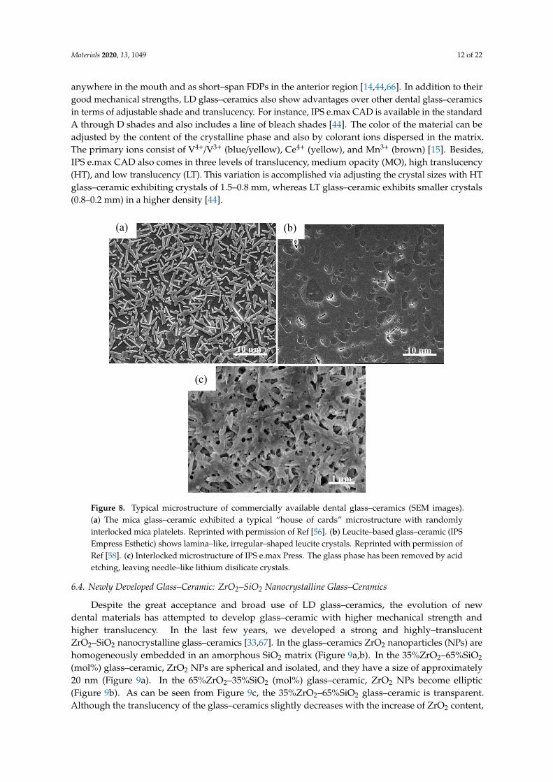
anywhere in the mouth and as short–span FDPs in the anterior region [14,44,66]. In addition to theirgood mechanical strengths, LD glass–ceramics also show advantages over other dental glass–ceramicsin terms of adjustable shade and translucency. For instance, IPS e.max CAD is available in the standardA through D shades and also includes a line of bleach shades [44]. The color of the material can beadjusted by the content of the crystalline phase and also by colorant ions dispersed in the matrix.The primary ions consist of V4+/V3+ (blue/yellow), Ce4+ (yellow), and Mn3+ (brown) [15]. Besides,IPS e.max CAD also comes in three levels of translucency, medium opacity (MO), high translucency(HT), and low translucency (LT). This variation is accomplished via adjusting the crystal sizes with HTglass–ceramic exhibiting crystals of 1.5–0.8 mm, whereas LT glass–ceramic exhibits smaller crystals(0.8–0.2 mm) in a higher density [44].Materials 2019, 12, x FOR PEER REVIEW 13 of 23
6.4. Newly Developed Glass–Ceramic: ZrO2–SiO2 Nanocrystalline Glass–Ceramics
Despite the great acceptance and broad use of LD glass–ceramics, the evolution of new dental
materials has attempted to develop glass–ceramic with higher mechanical strength and higher
translucency. In the last few years, we developed a strong and highly–translucent ZrO2–SiO2
nanocrystalline glass–ceramics [33,67]. In the glass–ceramics ZrO2 nanoparticles (NPs) are
homogeneously embedded in an amorphous SiO2 matrix (Figure 9a,b). In the 35%ZrO2–65%SiO2
(mol%) glass–ceramic, ZrO2 NPs are spherical and isolated, and they have a size of approximately 20
nm (Figure 9a). In the 65%ZrO2–35%SiO2 (mol%) glass–ceramic, ZrO2 NPs become elliptic (Figure
9b). As can be seen from Figure 9c, the 35%ZrO2–65%SiO2 glass–ceramic is transparent. Although the
translucency of the glass–ceramics slightly decreases with the increase of ZrO2 content, the 65%ZrO2–
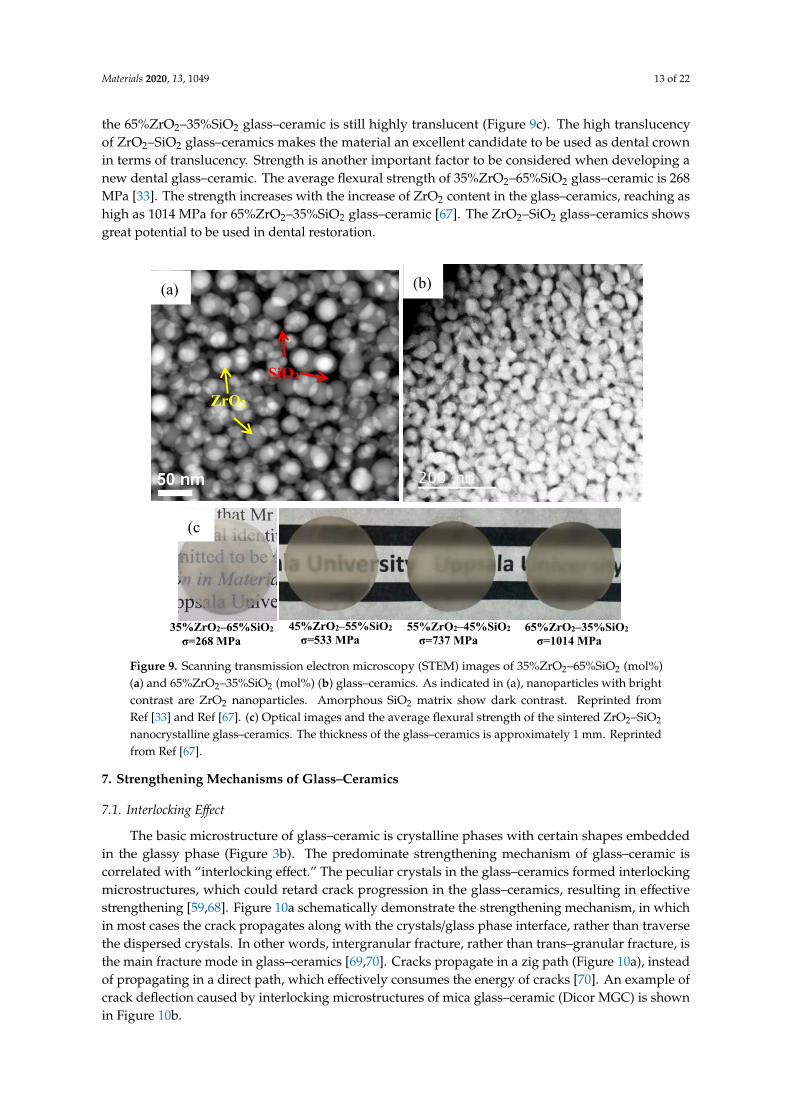
35%SiO2 glass–ceramic is still highly translucent (Figure 9c). The high translucency of ZrO2–SiO2
glass–ceramics makes the material an excellent candidate to be used as dental crown in terms of
translucency. Strength is another important factor to be considered when developing a new dental
glass–ceramic. The average flexural strength of 35%ZrO2–65%SiO2 glass–ceramic is 268 MPa [33]. The
strength increases with the increase of ZrO2 content in the glass–ceramics, reaching as high as 1014
MPa for 65%ZrO2–35%SiO2 glass–ceramic [67]. The ZrO2–SiO2 glass–ceramics shows great potential
to be used in dental restoration.
10 µm 10 µm
(c)
1 µm
(b) (a)
Figure 8. Typical microstructure of commercially available dental glass–ceramics (SEM images).(a) The mica glass–ceramic exhibited a typical “house of cards” microstructure with randomlyinterlocked mica platelets. Reprinted with permission of Ref [56]. (b) Leucite–based glass–ceramic (IPSEmpress Esthetic) shows lamina–like, irregular–shaped leucite crystals. Reprinted with permission ofRef [58]. (c) Interlocked microstructure of IPS e.max Press. The glass phase has been removed by acidetching, leaving needle–like lithium disilicate crystals.
6.4. Newly Developed Glass–Ceramic: ZrO2–SiO2 Nanocrystalline Glass–Ceramics
Despite the great acceptance and broad use of LD glass–ceramics, the evolution of newdental materials has attempted to develop glass–ceramic with higher mechanical strength andhigher translucency. In the last few years, we developed a strong and highly–translucentZrO2–SiO2 nanocrystalline glass–ceramics [33,67]. In the glass–ceramics ZrO2 nanoparticles (NPs) arehomogeneously embedded in an amorphous SiO2 matrix (Figure 9a,b). In the 35%ZrO2–65%SiO2
(mol%) glass–ceramic, ZrO2 NPs are spherical and isolated, and they have a size of approximately20 nm (Figure 9a). In the 65%ZrO2–35%SiO2 (mol%) glass–ceramic, ZrO2 NPs become elliptic(Figure 9b). As can be seen from Figure 9c, the 35%ZrO2–65%SiO2 glass–ceramic is transparent.Although the translucency of the glass–ceramics slightly decreases with the increase of ZrO2 content,
Materials 2020, 13, 1049 13 of 22
the 65%ZrO2–35%SiO2 glass–ceramic is still highly translucent (Figure 9c). The high translucencyof ZrO2–SiO2 glass–ceramics makes the material an excellent candidate to be used as dental crownin terms of translucency. Strength is another important factor to be considered when developing anew dental glass–ceramic. The average flexural strength of 35%ZrO2–65%SiO2 glass–ceramic is 268MPa [33]. The strength increases with the increase of ZrO2 content in the glass–ceramics, reaching ashigh as 1014 MPa for 65%ZrO2–35%SiO2 glass–ceramic [67]. The ZrO2–SiO2 glass–ceramics showsgreat potential to be used in dental restoration.Materials 2019, 12, x FOR PEER REVIEW 14 of 23
Figure 9. Scanning transmission electron microscopy (STEM) images of 35%ZrO2–65%SiO2 (mol%) (a)
and 65%ZrO2–35%SiO2 (mol%) (b) glass–ceramics. As indicated in (a), nanoparticles with bright
contrast are ZrO2 nanoparticles. Amorphous SiO2 matrix show dark contrast. Reprinted from Ref [33]
and Ref [67]. (c) Optical images and the average flexural strength of the sintered ZrO2–SiO2
nanocrystalline glass–ceramics. The thickness of the glass–ceramics is approximately 1 mm. Reprinted
from Ref [67].
7. Strengthening Mechanisms of Glass–Ceramics
7.1. Interlocking Effect
The basic microstructure of glass–ceramic is crystalline phases with certain shapes embedded in
the glassy phase (Figure 3b). The predominate strengthening mechanism of glass–ceramic is
correlated with “interlocking effect.” The peculiar crystals in the glass–ceramics formed interlocking
microstructures, which could retard crack progression in the glass–ceramics, resulting in effective
strengthening [59,68]. Figure 10a schematically demonstrate the strengthening mechanism, in which
in most cases the crack propagates along with the crystals/glass phase interface, rather than traverse
the dispersed crystals. In other words, intergranular fracture, rather than trans–granular fracture, is
the main fracture mode in glass–ceramics [69,70]. Cracks propagate in a zig path (Figure 10a), instead
of propagating in a direct path, which effectively consumes the energy of cracks [70]. An example of
crack deflection caused by interlocking microstructures of mica glass–ceramic (Dicor MGC) is shown
in Figure 10b.
(b) (a)
ZrO2
SiO2
35%ZrO2–65%SiO2 σ=268 MPa
45%ZrO2–55%SiO2
σ=533 MPa 55%ZrO2–45%SiO2
σ=737 MPa 65%ZrO2–35%SiO2
σ=1014 MPa
(c
Figure 9. Scanning transmission electron microscopy (STEM) images of 35%ZrO2–65%SiO2 (mol%)(a) and 65%ZrO2–35%SiO2 (mol%) (b) glass–ceramics. As indicated in (a), nanoparticles with brightcontrast are ZrO2 nanoparticles. Amorphous SiO2 matrix show dark contrast. Reprinted fromRef [33] and Ref [67]. (c) Optical images and the average flexural strength of the sintered ZrO2–SiO2
nanocrystalline glass–ceramics. The thickness of the glass–ceramics is approximately 1 mm. Reprintedfrom Ref [67].
7. Strengthening Mechanisms of Glass–Ceramics
7.1. Interlocking Effect
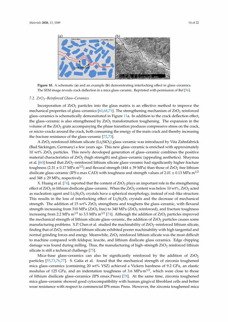
The basic microstructure of glass–ceramic is crystalline phases with certain shapes embeddedin the glassy phase (Figure 3b). The predominate strengthening mechanism of glass–ceramic iscorrelated with “interlocking effect.” The peculiar crystals in the glass–ceramics formed interlockingmicrostructures, which could retard crack progression in the glass–ceramics, resulting in effectivestrengthening [59,68]. Figure 10a schematically demonstrate the strengthening mechanism, in whichin most cases the crack propagates along with the crystals/glass phase interface, rather than traversethe dispersed crystals. In other words, intergranular fracture, rather than trans–granular fracture, isthe main fracture mode in glass–ceramics [69,70]. Cracks propagate in a zig path (Figure 10a), insteadof propagating in a direct path, which effectively consumes the energy of cracks [70]. An example ofcrack deflection caused by interlocking microstructures of mica glass–ceramic (Dicor MGC) is shownin Figure 10b.
Materials 2020, 13, 1049 14 of 22Materials 2019, 12, x FOR PEER REVIEW 15 of 23
7.2. ZrO2–Reinforced Glass–Ceramics
Incorporation of ZrO2 particles into the glass matrix is an effective method to improve the
mechanical properties of glass–ceramics [60,68,71]. The strengthening mechanism of ZrO2 reinforced
glass–ceramics is schematically demonstrated in Figure 11a. In addition to the crack deflection effect,
the glass–ceramic is also strengthened by ZrO2 transformation toughening. The expansion in the
volume of the ZrO2 grain accompanying the phase transition produces compressive stress on the
crack, or micro–cracks around the crack, both consuming the energy of the main crack and thereby
increasing the fracture resistance of the glass–ceramic [72,73].
A ZrO2 reinforced lithium silicate (Li2SiO3) glass–ceramic was introduced by Vita Zahnfabrick
(Bad Säckingen, Germany) a few years ago. This new glass–ceramic is enriched with approximately
10 wt% ZrO2 particles. This newly developed generation of glass–ceramic combines the positive
material characteristics of ZrO2 (high strength) and glass–ceramic (appealing aesthetics). Shaymaa et
al. [60] found that ZrO2–reinforced lithium silicate glass–ceramic had significantly higher fracture
toughness (2.31 ± 0.17 MPa m1/2) and flexural strength (444 ± 39 MPa) than those of ZrO2 free lithium
disilicate glass–ceramic (IPS e.max CAD) with toughness and strength values of 2.01 ± 0.13 MPa m1/2
and 348 ± 29 MPa, respectively.
X. Huang et al. [74]. reported that the content of ZrO2 plays an important role in the
strengthening effect of ZrO2 in lithium disilicate glass–ceramic. When the ZrO2 content was below 10
wt%, ZrO2 acted as nucleation agent and Li2Si2O5 crystals have a spherical morphology, instead of
rod–like structure. This results in the loss of interlocking effect of Li2Si2O5 crystals and the decrease
of mechanical strength. The addition of 15 wt% ZrO2 strengthens and toughens the glass–ceramic,
with flexural strength increasing from 310 MPa (ZrO2 free) to 340 MPa (ZrO2 reinforced), and fracture
toughness increasing from 2.2 MPa m1/2 to 3.5 MPa m1/2 [74]. Although the addition of ZrO2 particles
improved the mechanical strength of lithium silicate glass–ceramic, the addition of ZrO2 particles
causes some manufacturing problems. X.P. Chen et al. studied the machinability of ZrO2–reinforced
lithium silicate, finding that of ZrO2–reinforced lithium silicate exhibited poorer machinability with
high tangential and normal grinding forces and energy. Meanwhile, ZrO2 reinforced lithium silicate
was the most difficult to machine compared with feldspar, leucite, and lithium disilicate glass
ceramics. Edge chipping damage was found during milling. Thus, the manufacturing of high–
strength ZrO2 reinforced lithium silicate is still a technical challenge [75].
Mica–base glass–ceramics can also be significantly reinforced by the addition of ZrO2 particles
[55,73,76,77]. S. Galia et al. found that the mechanical strength of zirconia toughened mica glass–ceramics (containing 20 wt% YSZ) achieved a Vickers hardness of 9.2 GPa, an elastic modulus of 125
GPa, and an indentation toughness of 3.6 MPa∙m1/2, which were close to those of lithium disilicate
glass–ceramics (IPS emax.Press) [78]. At the same time, zirconia toughened mica glass–ceramic
showed good cytocompatibility with human gingival fibroblast cells and better wear resistance with
respect to commercial IPS emax Press. However, the zirconia toughened mica glass–ceramic had a
(a) (b)
Figure 10. A schematic (a) and an example (b) demonstrating interlocking effect in glass–ceramics.The SEM image reveals crack deflection in a mica glass–ceramic. Reprinted with permission of Ref [56].
7.2. ZrO2–Reinforced Glass–Ceramics
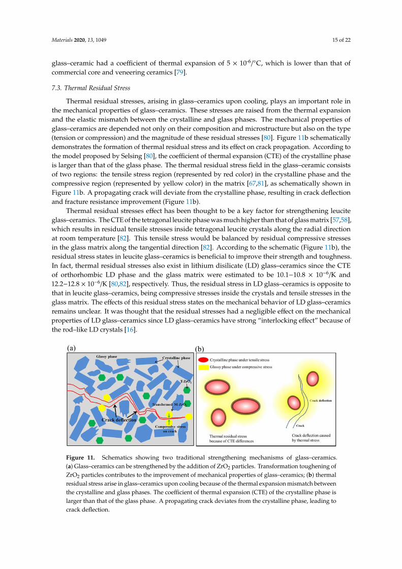
Incorporation of ZrO2 particles into the glass matrix is an effective method to improve themechanical properties of glass–ceramics [60,68,71]. The strengthening mechanism of ZrO2 reinforcedglass–ceramics is schematically demonstrated in Figure 11a. In addition to the crack deflection effect,the glass–ceramic is also strengthened by ZrO2 transformation toughening. The expansion in thevolume of the ZrO2 grain accompanying the phase transition produces compressive stress on the crack,or micro–cracks around the crack, both consuming the energy of the main crack and thereby increasingthe fracture resistance of the glass–ceramic [72,73].
A ZrO2 reinforced lithium silicate (Li2SiO3) glass–ceramic was introduced by Vita Zahnfabrick(Bad Säckingen, Germany) a few years ago. This new glass–ceramic is enriched with approximately10 wt% ZrO2 particles. This newly developed generation of glass–ceramic combines the positivematerial characteristics of ZrO2 (high strength) and glass–ceramic (appealing aesthetics). Shaymaaet al. [60] found that ZrO2–reinforced lithium silicate glass–ceramic had significantly higher fracturetoughness (2.31 ± 0.17 MPa m1/2) and flexural strength (444 ± 39 MPa) than those of ZrO2 free lithiumdisilicate glass–ceramic (IPS e.max CAD) with toughness and strength values of 2.01 ± 0.13 MPa m1/2
and 348 ± 29 MPa, respectively.X. Huang et al. [74]. reported that the content of ZrO2 plays an important role in the strengthening
effect of ZrO2 in lithium disilicate glass–ceramic. When the ZrO2 content was below 10 wt%, ZrO2 actedas nucleation agent and Li2Si2O5 crystals have a spherical morphology, instead of rod–like structure.This results in the loss of interlocking effect of Li2Si2O5 crystals and the decrease of mechanicalstrength. The addition of 15 wt% ZrO2 strengthens and toughens the glass–ceramic, with flexuralstrength increasing from 310 MPa (ZrO2 free) to 340 MPa (ZrO2 reinforced), and fracture toughnessincreasing from 2.2 MPa m1/2 to 3.5 MPa m1/2 [74]. Although the addition of ZrO2 particles improvedthe mechanical strength of lithium silicate glass–ceramic, the addition of ZrO2 particles causes somemanufacturing problems. X.P. Chen et al. studied the machinability of ZrO2–reinforced lithium silicate,finding that of ZrO2–reinforced lithium silicate exhibited poorer machinability with high tangential andnormal grinding forces and energy. Meanwhile, ZrO2 reinforced lithium silicate was the most difficultto machine compared with feldspar, leucite, and lithium disilicate glass ceramics. Edge chippingdamage was found during milling. Thus, the manufacturing of high–strength ZrO2 reinforced lithiumsilicate is still a technical challenge [75].
Mica–base glass–ceramics can also be significantly reinforced by the addition of ZrO2
particles [55,73,76,77]. S. Galia et al. found that the mechanical strength of zirconia toughenedmica glass–ceramics (containing 20 wt% YSZ) achieved a Vickers hardness of 9.2 GPa, an elasticmodulus of 125 GPa, and an indentation toughness of 3.6 MPa·m1/2, which were close to thoseof lithium disilicate glass–ceramics (IPS emax.Press) [78]. At the same time, zirconia toughenedmica glass–ceramic showed good cytocompatibility with human gingival fibroblast cells and betterwear resistance with respect to commercial IPS emax Press. However, the zirconia toughened mica
Materials 2020, 13, 1049 15 of 22
glass–ceramic had a coefficient of thermal expansion of 5 × 10⁻⁶/◦C, which is lower than that ofcommercial core and veneering ceramics [79].
7.3. Thermal Residual Stress
Thermal residual stresses, arising in glass–ceramics upon cooling, plays an important role inthe mechanical properties of glass–ceramics. These stresses are raised from the thermal expansionand the elastic mismatch between the crystalline and glass phases. The mechanical properties ofglass–ceramics are depended not only on their composition and microstructure but also on the type(tension or compression) and the magnitude of these residual stresses [80]. Figure 11b schematicallydemonstrates the formation of thermal residual stress and its effect on crack propagation. According tothe model proposed by Selsing [80], the coefficient of thermal expansion (CTE) of the crystalline phaseis larger than that of the glass phase. The thermal residual stress field in the glass–ceramic consistsof two regions: the tensile stress region (represented by red color) in the crystalline phase and thecompressive region (represented by yellow color) in the matrix [67,81], as schematically shown inFigure 11b. A propagating crack will deviate from the crystalline phase, resulting in crack deflectionand fracture resistance improvement (Figure 11b).
Thermal residual stresses effect has been thought to be a key factor for strengthening leuciteglass–ceramics. The CTE of the tetragonal leucite phase was much higher than that of glass matrix [57,58],which results in residual tensile stresses inside tetragonal leucite crystals along the radial directionat room temperature [82]. This tensile stress would be balanced by residual compressive stressesin the glass matrix along the tangential direction [82]. According to the schematic (Figure 11b), theresidual stress states in leucite glass–ceramics is beneficial to improve their strength and toughness.In fact, thermal residual stresses also exist in lithium disilicate (LD) glass–ceramics since the CTEof orthorhombic LD phase and the glass matrix were estimated to be 10.1−10.8 × 10⁻⁶/K and12.2−12.8 × 10⁻⁶/K [80,82], respectively. Thus, the residual stress in LD glass–ceramics is opposite tothat in leucite glass–ceramics, being compressive stresses inside the crystals and tensile stresses in theglass matrix. The effects of this residual stress states on the mechanical behavior of LD glass–ceramicsremains unclear. It was thought that the residual stresses had a negligible effect on the mechanicalproperties of LD glass–ceramics since LD glass–ceramics have strong “interlocking effect” because ofthe rod–like LD crystals [16].
Materials 2019, 12, x FOR PEER REVIEW 16 of 23
coefficient of thermal expansion of 5 × 10‐6/°C, which is lower than that of commercial core and
veneering ceramics [79].
7.3. Thermal Residual Stress
Thermal residual stresses, arising in glass–ceramics upon cooling, plays an important role in the
mechanical properties of glass–ceramics. These stresses are raised from the thermal expansion and
the elastic mismatch between the crystalline and glass phases. The mechanical properties of glass–
ceramics are depended not only on their composition and microstructure but also on the type (tension
or compression) and the magnitude of these residual stresses [80]. Figure 11b schematically
demonstrates the formation of thermal residual stress and its effect on crack propagation. According
to the model proposed by Selsing [80], the coefficient of thermal expansion (CTE) of the crystalline
phase is larger than that of the glass phase. The thermal residual stress field in the glass–ceramic
consists of two regions: the tensile stress region (represented by red color) in the crystalline phase
and the compressive region (represented by yellow color) in the matrix [67,81], as schematically
shown in Figure 11b. A propagating crack will deviate from the crystalline phase, resulting in crack
deflection and fracture resistance improvement (Figure 11b).
Thermal residual stresses effect has been thought to be a key factor for strengthening leucite
glass–ceramics. The CTE of the tetragonal leucite phase was much higher than that of glass matrix
[57,58], which results in residual tensile stresses inside tetragonal leucite crystals along the radial
direction at room temperature [82]. This tensile stress would be balanced by residual compressive
stresses in the glass matrix along the tangential direction [82]. According to the schematic (Figure
11b), the residual stress states in leucite glass–ceramics is beneficial to improve their strength and
toughness. In fact, thermal residual stresses also exist in lithium disilicate (LD) glass–ceramics since
the CTE of orthorhombic LD phase and the glass matrix were estimated to be 10.1−10.8 × 10⁻⁶/K and
12.2−12.8 × 10⁻⁶/K [80,82], respectively. Thus, the residual stress in LD glass–ceramics is opposite to
that in leucite glass–ceramics, being compressive stresses inside the crystals and tensile stresses in
the glass matrix. The effects of this residual stress states on the mechanical behavior of LD glass–
ceramics remains unclear. It was thought that the residual stresses had a negligible effect on the
mechanical properties of LD glass–ceramics since LD glass–ceramics have strong “interlocking
effect” because of the rod–like LD crystals [16].
Figure 11. Schematics showing two traditional strengthening mechanisms of glass–ceramics. (a)
Glass–ceramics can be strengthened by the addition of ZrO2 particles. Transformation toughening of
ZrO2 particles contributes to the improvement of mechanical properties of glass–ceramics; (b) thermal
residual stress arise in glass–ceramics upon cooling because of the thermal expansion mismatch
between the crystalline and glass phases. The coefficient of thermal expansion (CTE) of the crystalline
phase is larger than that of the glass phase. A propagating crack deviates from the crystalline phase,
leading to crack deflection.
(a) (b)
Figure 11. Schematics showing two traditional strengthening mechanisms of glass–ceramics.(a) Glass–ceramics can be strengthened by the addition of ZrO2 particles. Transformation toughening ofZrO2 particles contributes to the improvement of mechanical properties of glass–ceramics; (b) thermalresidual stress arise in glass–ceramics upon cooling because of the thermal expansion mismatch betweenthe crystalline and glass phases. The coefficient of thermal expansion (CTE) of the crystalline phase islarger than that of the glass phase. A propagating crack deviates from the crystalline phase, leading tocrack deflection.
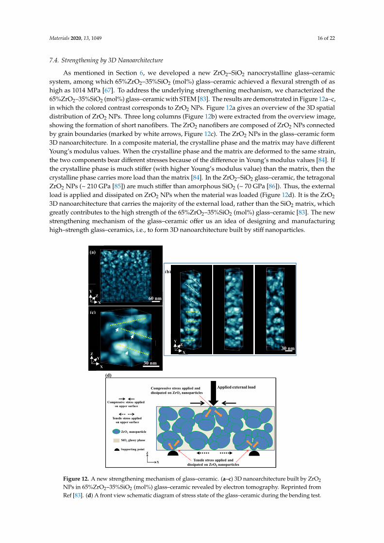
Materials 2020, 13, 1049 16 of 22
7.4. Strengthening by 3D Nanoarchitecture
As mentioned in Section 6, we developed a new ZrO2–SiO2 nanocrystalline glass–ceramicsystem, among which 65%ZrO2–35%SiO2 (mol%) glass–ceramic achieved a flexural strength of ashigh as 1014 MPa [67]. To address the underlying strengthening mechanism, we characterized the65%ZrO2–35%SiO2 (mol%) glass–ceramic with STEM [83]. The results are demonstrated in Figure 12a–c,in which the colored contrast corresponds to ZrO2 NPs. Figure 12a gives an overview of the 3D spatialdistribution of ZrO2 NPs. Three long columns (Figure 12b) were extracted from the overview image,showing the formation of short nanofibers. The ZrO2 nanofibers are composed of ZrO2 NPs connectedby grain boundaries (marked by white arrows, Figure 12c). The ZrO2 NPs in the glass–ceramic form3D nanoarchitecture. In a composite material, the crystalline phase and the matrix may have differentYoung’s modulus values. When the crystalline phase and the matrix are deformed to the same strain,the two components bear different stresses because of the difference in Young’s modulus values [84]. Ifthe crystalline phase is much stiffer (with higher Young’s modulus value) than the matrix, then thecrystalline phase carries more load than the matrix [84]. In the ZrO2–SiO2 glass–ceramic, the tetragonalZrO2 NPs (~ 210 GPa [85]) are much stiffer than amorphous SiO2 (~ 70 GPa [86]). Thus, the externalload is applied and dissipated on ZrO2 NPs when the material was loaded (Figure 12d). It is the ZrO2
3D nanoarchitecture that carries the majority of the external load, rather than the SiO2 matrix, whichgreatly contributes to the high strength of the 65%ZrO2–35%SiO2 (mol%) glass–ceramic [83]. The newstrengthening mechanism of the glass–ceramic offer us an idea of designing and manufacturinghigh–strength glass–ceramics, i.e., to form 3D nanoarchitecture built by stiff nanoparticles.
Materials 2019, 12, x FOR PEER REVIEW 17 of 23
7.4. Strengthening by 3D Nanoarchitecture
As mentioned in Section 6, we developed a new ZrO2–SiO2 nanocrystalline glass–ceramic
system, among which 65%ZrO2–35%SiO2 (mol%) glass–ceramic achieved a flexural strength of as
high as 1014 MPa [67]. To address the underlying strengthening mechanism, we characterized the
65%ZrO2–35%SiO2 (mol%) glass–ceramic with STEM [83]. The results are demonstrated in Figure 12
a–c, in which the colored contrast corresponds to ZrO2 NPs. Figure 12a gives an overview of the 3D
spatial distribution of ZrO2 NPs. Three long columns (Figure 12b) were extracted from the overview
image, showing the formation of short nanofibers. The ZrO2 nanofibers are composed of ZrO2 NPs
connected by grain boundaries (marked by white arrows, Figure 12c). The ZrO2 NPs in the glass–
ceramic form 3D nanoarchitecture. In a composite material, the crystalline phase and the matrix may
have different Young’s modulus values. When the crystalline phase and the matrix are deformed to
the same strain, the two components bear different stresses because of the difference in Young’s
modulus values [84]. If the crystalline phase is much stiffer (with higher Young’s modulus value)
than the matrix, then the crystalline phase carries more load than the matrix [84]. In the ZrO2–SiO2
glass–ceramic, the tetragonal ZrO2 NPs (~ 210 GPa [85]) are much stiffer than amorphous SiO2 (~ 70
GPa [86]). Thus, the external load is applied and dissipated on ZrO2 NPs when the material was
loaded (Figure 12d). It is the ZrO2 3D nanoarchitecture that carries the majority of the external load,
rather than the SiO2 matrix, which greatly contributes to the high strength of the 65%ZrO2–35%SiO2
(mol%) glass–ceramic [83]. The new strengthening mechanism of the glass–ceramic offer us an idea
of designing and manufacturing high–strength glass–ceramics, i.e., to form 3D nanoarchitecture built
by stiff nanoparticles.
(a)
60 nm X
Z Y
(c)
X
Y Z
30 nm
(b)
30 nm Z
Y
X
(d)
Figure 12. A new strengthening mechanism of glass–ceramic. (a–c) 3D nanoarchitecture built by ZrO2
NPs in 65%ZrO2–35%SiO2 (mol%) glass–ceramic revealed by electron tomography. Reprinted fromRef [83]. (d) A front view schematic diagram of stress state of the glass–ceramic during the bending test.
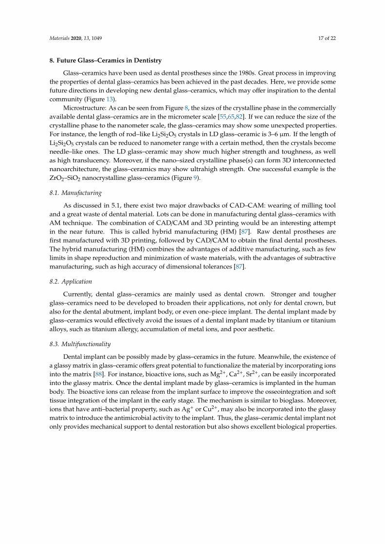
Materials 2020, 13, 1049 17 of 22
8. Future Glass–Ceramics in Dentistry
Glass–ceramics have been used as dental prostheses since the 1980s. Great process in improvingthe properties of dental glass–ceramics has been achieved in the past decades. Here, we provide somefuture directions in developing new dental glass–ceramics, which may offer inspiration to the dentalcommunity (Figure 13).
Microstructure: As can be seen from Figure 8, the sizes of the crystalline phase in the commerciallyavailable dental glass–ceramics are in the micrometer scale [55,65,82]. If we can reduce the size of thecrystalline phase to the nanometer scale, the glass–ceramics may show some unexpected properties.For instance, the length of rod–like Li2Si2O5 crystals in LD glass–ceramic is 3–6 µm. If the length ofLi2Si2O5 crystals can be reduced to nanometer range with a certain method, then the crystals becomeneedle–like ones. The LD glass–ceramic may show much higher strength and toughness, as wellas high translucency. Moreover, if the nano–sized crystalline phase(s) can form 3D interconnectednanoarchitecture, the glass–ceramics may show ultrahigh strength. One successful example is theZrO2–SiO2 nanocrystalline glass–ceramics (Figure 9).
8.1. Manufacturing
As discussed in 5.1, there exist two major drawbacks of CAD–CAM: wearing of milling tooland a great waste of dental material. Lots can be done in manufacturing dental glass–ceramics withAM technique. The combination of CAD/CAM and 3D printing would be an interesting attemptin the near future. This is called hybrid manufacturing (HM) [87]. Raw dental prostheses arefirst manufactured with 3D printing, followed by CAD/CAM to obtain the final dental prostheses.The hybrid manufacturing (HM) combines the advantages of additive manufacturing, such as fewlimits in shape reproduction and minimization of waste materials, with the advantages of subtractivemanufacturing, such as high accuracy of dimensional tolerances [87].
8.2. Application
Currently, dental glass–ceramics are mainly used as dental crown. Stronger and tougherglass–ceramics need to be developed to broaden their applications, not only for dental crown, butalso for the dental abutment, implant body, or even one–piece implant. The dental implant made byglass–ceramics would effectively avoid the issues of a dental implant made by titanium or titaniumalloys, such as titanium allergy, accumulation of metal ions, and poor aesthetic.
8.3. Multifunctionality
Dental implant can be possibly made by glass–ceramics in the future. Meanwhile, the existence ofa glassy matrix in glass–ceramic offers great potential to functionalize the material by incorporating ionsinto the matrix [88]. For instance, bioactive ions, such as Mg2+, Ca2+, Sr2+, can be easily incorporatedinto the glassy matrix. Once the dental implant made by glass–ceramics is implanted in the humanbody. The bioactive ions can release from the implant surface to improve the osseointegration and softtissue integration of the implant in the early stage. The mechanism is similar to bioglass. Moreover,ions that have anti–bacterial property, such as Ag+ or Cu2+, may also be incorporated into the glassymatrix to introduce the antimicrobial activity to the implant. Thus, the glass–ceramic dental implant notonly provides mechanical support to dental restoration but also shows excellent biological properties.
Materials 2020, 13, 1049 18 of 22
Materials 2019, 12, x FOR PEER REVIEW 19 of 23
Figure 13. A perspective and outlook for future directions in developing new dental glass–ceramics.
9. Summary
In dentistry, glass–ceramics with appealing aesthetics and adequate strength are attracting
extensive attention of material scientists, dentists, and patients. Mica–based, leucite–based, and
lithium disilicate glass–ceramics are the most prevalent clinically used examples of dental glass–
ceramics. However, compared with sintered dental ceramics (e.g., Y–TZP), commercially available
dental glass–ceramics have much lower strength and fracture toughness that limits their wider
applications in dentistry, such as multi–unit prostheses involving molar restoration, thereby
improving the strength and toughness of glass–ceramics, meanwhile maintaining their high
translucency is the main task of optimizing the existing or developing new glass–ceramics. As for the
manufacturing method, additive manufacturing shows great potential. However, a lot of issues, such
as low accuracy, need to be solved before additive manufacturing becomes the predominate
manufacturing in dentistry. Glass phase can be modified to incorporate with specific ions, e.g., Ag+,
Cu2+, and Sr2+, to simultaneously introduce more than one desirable biological properties to glass–
ceramics.
Author Contributions: L.F. wrote the manuscript; H.E. and W.X. took part in revising the manuscript. All
authors have read and agreed to the published version of the manuscript.
Funding: This research is funded by the start‐up funding of Central South University.
Acknowledgments: Le Fu acknowledge the start–up funding provided by Central South University.
Conflicts of Interest: The authors declare no conflict of interest.
Reference
1. Zanotto, E.D. A bright future for glass‐ceramics. Am. Ceram. Soc. Bull. 2010, 89, 19–27.
2. Larry, S.M.B.; Hench, L. Ceramics, glasses, and glass‐ceramics: Basic principles. In Biomaterials Science: An
Introduction to Materials in Medicine, 3rd ed.; Academic Press: Cambridge, MA, USA, 2012.
3. Pinckney, L.R. Glass ceramics. In Encyclopedia of Materials: Science and Technology, 2nd ed.; Pergamon: Oxford,
UK, 2001.
4. El‐Meliegy, E.; van Noort, R. Machinable mica dental glass‐ceramics. In Glasses and Glass Ceramics for
Medical Applications; Springer: New York, NY, USA, 2012; pp. 1–244, doi:10.1007/978‐1‐4614‐1228‐1.
5. Hoeland, W.; Beall, G.H. (Eds.) Glass‐Ceramic Technology, 2nd ed.; The American Ceramic Society/Wiley:
New York, NY, USA, 2010.
6. Beall, G.H. Milestones in glass‐ceramics: A personal perspective. Int. J. Appl. Glas. Sci. 2014, 5, 93–103,
doi:10.1111/ijag.12063.
7. Filser, F. Direct Ceramic Machining of Dental Restorations. Ph.D. Thesis, Swiss Federal Institute of
Technology Zurich, Zurich, Switzerland, 2001, doi:10.3929/ethz‐a‐004183626.
8. Edward, A.M; Phong, T.C. Ceramics in Dentistry—Part I: Classes of Materials. Inside Dent. 2009, 7, 94–103.
9. Zhang, Y.; Kelly, J.R. Dental ceramics for restoration and metal veneering. Dent. Clin. North Am. 2017, 61,
797–819, doi:10.1016/j.cden.2017.06.005.
Figure 13. A perspective and outlook for future directions in developing new dental glass–ceramics.
9. Summary
In dentistry, glass–ceramics with appealing aesthetics and adequate strength are attractingextensive attention of material scientists, dentists, and patients. Mica–based, leucite–based, and lithiumdisilicate glass–ceramics are the most prevalent clinically used examples of dental glass–ceramics.However, compared with sintered dental ceramics (e.g., Y–TZP), commercially available dentalglass–ceramics have much lower strength and fracture toughness that limits their wider applicationsin dentistry, such as multi–unit prostheses involving molar restoration, thereby improving the strengthand toughness of glass–ceramics, meanwhile maintaining their high translucency is the main task ofoptimizing the existing or developing new glass–ceramics. As for the manufacturing method, additivemanufacturing shows great potential. However, a lot of issues, such as low accuracy, need to be solvedbefore additive manufacturing becomes the predominate manufacturing in dentistry. Glass phase canbe modified to incorporate with specific ions, e.g., Ag+, Cu2+, and Sr2+, to simultaneously introducemore than one desirable biological properties to glass–ceramics.
Author Contributions: L.F. wrote the manuscript; H.E. and W.X. took part in revising the manuscript. All authorshave read and agreed to the published version of the manuscript.
Funding: This research is funded by the start-up funding of Central South University.
Acknowledgments: Le Fu acknowledge the start–up funding provided by Central South University.
Conflicts of Interest: The authors declare no conflict of interest.
References
1. Zanotto, E.D. A bright future for glass-ceramics. Am. Ceram. Soc. Bull. 2010, 89, 19–27.2. Larry, S.M.B.; Hench, L. Ceramics, glasses, and glass-ceramics: Basic principles. In Biomaterials Science:
An Introduction to Materials in Medicine, 3rd ed.; Academic Press: Cambridge, MA, USA, 2012.3. Pinckney, L.R. Glass ceramics. In Encyclopedia of Materials: Science and Technology, 2nd ed.; Pergamon: Oxford,
UK, 2001.4. El-Meliegy, E.; van Noort, R. Machinable mica dental glass-ceramics. In Glasses and Glass Ceramics for Medical
Applications; Springer: New York, NY, USA, 2012; pp. 1–244. [CrossRef]5. Hoeland, W.; Beall, G.H. (Eds.) Glass-Ceramic Technology, 2nd ed.; The American Ceramic Society/Wiley:
New York, NY, USA, 2010.6. Beall, G.H. Milestones in glass-ceramics: A personal perspective. Int. J. Appl. Glas. Sci. 2014, 5, 93–103.
[CrossRef]7. Filser, F. Direct Ceramic Machining of Dental Restorations. Ph.D. Thesis, Swiss Federal Institute of Technology
Zurich, Zurich, Switzerland, 2001. [CrossRef]8. Edward, A.M.; Phong, T.C. Ceramics in Dentistry—Part I: Classes of Materials. Inside Dent. 2009, 7, 94–103.9. Zhang, Y.; Kelly, J.R. Dental ceramics for restoration and metal veneering. Dent. Clin. N. Am. 2017, 61,
797–819. [CrossRef] [PubMed]
Materials 2020, 13, 1049 19 of 22
10. Da Silva, L.H.; de Lima, E.; Miranda, D.P.R.B.; Favero, S.S.; Lohbauer, U.; Cesar, P.F. Dental ceramics: A reviewof new materials and processing methods. Braz. Oral Res. 2017, 31, e58. [CrossRef]
11. Ritzberger, C.; Apel, E.; Höland, W.; Peschke, A.; Rheinberger, V.M. Properties and clinical application ofthree types of dental glass-ceramics and ceramics for CAD-CAM technologies. Materials 2010, 3, 3700–3713.[CrossRef]
12. Montazerian, M.; Zanotto, E.D. Bioactive and inert dental glass-ceramics. J. Biomed. Mater. Res. Part A 2016,1, 619–639. [CrossRef]
13. Rekow, E.D.; Silva, N.R.F.A.; Coelho, P.G.; Zhang, Y.; Guess, P.; Thompson, V.P. Performance of dentalceramics: Challenges for improvements. J. Dent. Res. 2011, 90, 937–952. [CrossRef]
14. Ivoclar-Vivadent. Press Scientific Documentation IPS e.max®; Ivoclar Vivadent: Liechtenstein, 2011.15. Willard, A.; Gabriel Chu, T.M. The science and application of IPS e.Max dental ceramic. Kaohsiung J. Med. Sci.
2018, 34, 238–242. [CrossRef]16. Serbena, F.C.; Mathias, I.; Foerster, C.E.; Zanotto, E.D. Crystallization toughening of a model glass-ceramic.
Acta Mater. 2015, 86, 216–228. [CrossRef]17. Kleebusch, E.; Patzig, C.; Höche, T.; Rüssel, C. The evidence of phase separation droplets in the crystallization
process of a Li2O-Al2O3-SiO2 glass with TiO2 as nucleating agent—An X-ray diffraction and (S)TEM-studysupported by EDX-analysis. Ceram. Int. 2018, 44, 2919–2926. [CrossRef]
18. Alekseeva, I.; Dymshits, O.; Tsenter, M.; Zhilin, A.; Golubkov, V.; Denisov, I.; Skoptsov, N.; Malyarevich, A.;Yumashev, K. Optical applications of glass-ceramics. J. Non Cryst. Solids 2010, 356, 3042–3058. [CrossRef]
19. Hench, L.L.; Polak, J.M. Third-generation biomedical materials. Science 2002, 295, 1014–1017. [CrossRef][PubMed]
20. Inda, Y.; Katoh, T.; Baba, M. Development of all-solid lithium-ion battery using Li-ion conductingglass-ceramics. J. Power Sources 2007, 174, 741–744. [CrossRef]
21. James, P.F. Glass ceramics: New compositions and uses. J. Non Cryst. Solids. 1995, 181, 1–15. [CrossRef]22. Fernandes, H.R.; Tulyaganov, D.U.; Goel, A.; Ferreira, J.M.F. Effect of K2O on structure-property relationships
and phase transformations in Li2O-SiO2 glasses. J. Eur. Ceram. Soc. 2012, 32, 291–298. [CrossRef]23. Zhu, T.; Xie, Z.; Han, Y.; Li, S. Microstructure and mechanical properties of ZTA composites fabricated by
oscillatory pressure sintering. Ceram. Int. 2018, 44, 505–510. [CrossRef]24. Natarajan, S. Glass-ceramic technology, second edition by Wolfram Holand and George H. Beall. Mater. Manuf.
Process. 2016, 31, 550–551. [CrossRef]25. Deubener, J.; Allix, M.; Davis, M.J.; Duran, A.; Höche, T.; Honma, T.; Komatsu, T.; Krüger, S.; Mitra, I.;
Müller, R.; et al. Updated definition of glass-ceramics. J. Non Cryst. Solids. 2018, 501, 3–10. [CrossRef]26. Kleebusch, E.; Patzig, C.; Höche, T.; Rüssel, C. Phase formation during crystallization of a Li2O–Al2O3–SiO2
glass with ZrO2 as nucleating agent—An X-ray diffraction and (S)TEM-study. Ceram. Int. 2017, 43, 9769–9777.[CrossRef]
27. Zhao, T.; Qin, Y.; Wang, B.; Yang, J.F. Improved densification and properties of pressureless-sintered lithiumdisilicate glass-ceramics. Mater. Sci. Eng. A 2014, 620, 399–406. [CrossRef]
28. Yong, L.; Tan, Y.; Grover, L.; Guo, Y.; Bowei, L. A mica/nepheline glass-ceramic prepared by melting andpowder metallurgy at low temperatures. Mater. Today Commun. 2017, 11, 87–93. [CrossRef]
29. Zhang, P.; Li, X.; Yang, J.; Xu, S. Effect of heat treatment on the microstructure and properties of lithiumdisilicate glass-ceramics. J. Non Cryst. Solids 2014, 402, 101–105. [CrossRef]
30. Chenu, S.; Véron, E.; Genevois, C.; Matzen, G.; Cardinal, T.; Etienne, A.; Massiot, D.; Allix, M. Tuneablenanostructuring of highly transparent zinc gallogermanate glasses and glass-ceramics. Adv. Opt. Mater.2014, 2, 364–372. [CrossRef]
31. Mallik, A.; Basumajumdar, A.; Kundu, P.; Maiti, P.K. Some studies on nucleation,crystallization, microstructure and mechanical properties of mica glass-ceramics in the system0.2BaO·0.8K2O·4MgO·Al2O3·6SiO2·2MgF2. Ceram. Int. 2013, 39, 2551–2559. [CrossRef]
32. Yan, T.; Zhang, W.; Chen, X.; Wang, F.; Bai, S. Sintering densification behaviors and crystallizationcharacteristics of glass–ceramics formed by two types of CaO–B2O3–SiO2 glass. J. Mater. Sci. Mater. Electron.2019, 30, 10352–10359. [CrossRef]
33. Fu, L.; Wu, C.; Grandfield, K.; Unosson, E.; Chang, J.; Engqvist, H.; Xia, W. Transparent single crystallineZrO2-SiO2 glass nanoceramic sintered by SPS. J. Eur. Ceram. Soc. 2016, 36, 3487–3494. [CrossRef]
Materials 2020, 13, 1049 20 of 22
34. Nogami, M.; Nagasaka, K. Toughened glass-ceramics in the ZrO2-Al2O3-SiO2 system prepared by the sol-gelprocess. J. Mater. Sci. 1991, 26, 3665–3669. [CrossRef]
35. Zhang, Y.; Sailer, I.; Lawn, B.R. Fatigue of dental ceramics. J. Dent. 2013, 41, 1135–1147. [CrossRef]36. Kelly, J. Ceramics in restorative and prosthetic dentistry. Annu. Rev. Mater. Sci. 1997, 27, 443–468. [CrossRef]37. Yilmaz, H.; Aydin, C.; Gul, B.E. Flexural strength and fracture toughness of dental core ceramics. J. Prosthet.
Dent. 2007, 98, 120–128. [CrossRef]38. Arvind, S.; Nina, S. Dental ceramics: An update. J. Conserv. Dent. 2010, 13, 195–203. [CrossRef]39. Miragaya, L.M.; Guimarães, R.B.; de Assunção e Souza, R.O.; dos Santos Botelho, G.; Antunes Guimarães, J.G.;
da Silva, E.M. Effect of intra-oral aging on t→m phase transformation, microstructure, and mechanicalproperties of Y-TZP dental ceramics. J. Mech. Behav. Biomed. Mater. 2017, 72, 14–21. [CrossRef] [PubMed]
40. ISO. International Standard ISO 6872 Dentistry—Ceramic Materials; ISO: Geneva, Switzerland, 2015.41. Santos, M.J.M.C.; Costa, M.D.; Rubo, J.H.; Pegoraro, L.F. Current all-ceramic systems in dentistry: A review.
Compend. Contin. Educ. Dent. 2015, 36, 31–38.42. El Ghoul, W.A.; Özcan, M.; Ounsi, H.; Tohme, H.; Salameh, Z. Effect of different CAD-CAM materials on the
marginal and internal adaptation of endocrown restorations: An in vitro study. J. Prosthet. Dent. 2019, 123,128–134. [CrossRef]
43. Sedrez-Porto, J.A.; de Oliveira da Rosa, W.L.; da Silva, A.F.; Münchow, E.A.; Pereira-Cenci, T. Endocrownrestorations: A systematic review and meta-analysis. J. Dent. 2016, 52, 8–14. [CrossRef]
44. Ivoclar-Vivadent. CAD Scientific Documentation IPS e.max®; Ivoclar Vivadent: Liechtenstein, 2005.45. Tidehag, P.; Shen, Z. Digital dentistry calls the change of ceramics and ceramic processes. Adv. Appl. Ceram.
2019, 118, 83–90. [CrossRef]46. Hugo, L.; Jean, D.; Bruno, J.; Michel, F. Dental biomaterials for chairside CAD/CAM: State of the art. J. Adv.
Prosthodont. 2017, 9, 486–495. [CrossRef]47. Galante, R.; Figueiredo-Pina, C.G.; Serro, A.P. Additive manufacturing of ceramics for dental applications:
A review. Dent. Mater. 2019, 35, 825–846. [CrossRef]48. Chen, Z.; Li, Z.; Li, J.; Liu, C.; Lao, C.; Fu, Y.; Liu, C.; Li, Y.; Wang, P.; He, Y. 3D printing of ceramics: A review.
J. Eur. Ceram. Soc. 2019, 39, 661–687. [CrossRef]49. Wilkes, J.; Hagedorn, Y.C.; Meiners, W.; Wissenbach, K. Additive manufacturing of ZrO2-Al2O3 ceramic
components by selective laser melting. Rapid Prototyp. J. 2013, 19, 51–57. [CrossRef]50. Javaid, M.; Haleem, A. Current status and applications of additive manufacturing in dentistry:
A literature-based review. J. Oral Biol. Craniofacial Res. 2019, 9, 179–185. [CrossRef] [PubMed]51. Özkol, E.; Zhang, W.; Ebert, J.; Telle, R. Potentials of the “Direct inkjet printing” method for manufacturing
3Y-TZP based dental restorations. J. Eur. Ceram. Soc. 2012, 32, 2193–2201. [CrossRef]52. Gahler, A.; Heinrich, J.G.; Günster, J. Direct laser sintering of Al2O3-SiO2 dental ceramic components by
layer-wise slurry deposition. J. Am. Ceram. Soc. 2006, 89, 3076–3080. [CrossRef]53. Li, H.; Song, L.; Sun, J.; Ma, J.; Shen, Z. Dental ceramic prostheses by stereolithography-based additive
manufacturing: Potentials and challenges. Adv. Appl. Ceram. 2019, 118, 30–36. [CrossRef]54. Gailevicius, D.; Padolskyte, V.; Mikoliunaite, L.; Šakirzanovas, S.; Juodkazis, S.; Malinauskas, M.
Additive-manufacturing of 3D glass-ceramics down to nanoscale resolution. Nanoscale Horizons 2019,4, 647–651. [CrossRef]
55. Gali, S. Mica glass ceramics for dental restorations. Mater. Technol. 2019, 34, 2–11. [CrossRef]56. Denry, I.L.; Holloway, J.A. Effect of heat pressing on the mechanical properties of a mica-based glass-ceramic.
J. Biomed. Mater. Res. Part B Appl. Biomater. 2004, 70, 37–42. [CrossRef]57. Chen, X.; Chadwick, T.C.; Wilson, R.M.; Hill, R.G.; Cattell, M.J. Crystallization and flexural strength
optimization of fine-grained leucite glass-ceramics for dentistry. Dent. Mater. 2011, 27, 1153–1161. [CrossRef]58. Theocharopoulos, A.; Chen, X.; Wilson, R.M.; Hill, R.; Cattell, M.J. Crystallization of high-strength nano-scale
leucite glass-ceramics. Dent. Mater. 2013, 29, 1149–1157. [CrossRef]59. Zhang, P.; Li, X.; Yang, J.; Xu, S. The crystallization and microstructure evolution of lithium disilicate-based
glass-ceramic. J. Non Cryst. Solids 2014, 392–393, 26–30. [CrossRef]60. Elsaka, S.E.; Elnaghy, A.M. Mechanical properties of zirconia reinforced lithium silicate glass-ceramic.
Dent. Mater. 2016, 32, 908–914. [CrossRef] [PubMed]61. Xiang, Q.; Liu, Y.; Sheng, X.; Dan, X. Preparation of mica-based glass-ceramics with needle-like fluorapatite.
Dent. Mater. 2007, 23, 251–258. [CrossRef] [PubMed]
Materials 2020, 13, 1049 21 of 22
62. Ivoclar-Vivadent. Classic Scientific Documentation IPS e.max®; Ivoclar Vivadent: Schaan, Liechtenstein, 2003.[CrossRef]
63. Esquivel-Upshaw, J.F.; Anusavice, K.J.; Young, H.; Jones, J.; Gibbs, C. Clinical performance of a lithiadisilicate-based core ceramic for three-unit posterior FPDs. Int. J. Prosthodont. 2004, 17, 469–475.
64. Li, R.W.K.; Chow, T.W.; Matinlinna, J.P. Ceramic dental biomaterials and CAD/CAM technology: State of theart. J. Prosthodont. Res. 2014, 58, 208–216. [CrossRef]
65. Lohbauer, U.; Belli, R.; Abdalla Alonso, A.; Goetz-Neunhoeffer, F.; Hurle, K. Effect of sintering parameterson phase evolution and strength of dental lithium silicate glass-ceramics. Dent. Mater. 2019, 35, 1360–1369.[CrossRef]
66. Kang, S.-H.; Chang, J.; Son, H.-H. Flexural strength and microstructure of two lithium disilicate glass ceramicsfor CAD/CAM restoration in the dental clinic. Restor. Dent. Endod. 2013, 38, 134–140. [CrossRef]
67. Fu, L.; Engqvist, H.; Xia, W. Highly translucent and strong ZrO2-SiO2 nanocrystalline glass ceramic preparedby sol-gel method and spark plasma sintering with fine 3D microstructure for dental restoration. J. Eur.Ceram. Soc. 2017, 37, 4067–4081. [CrossRef]
68. Hallmann, L.; Ulmer, P.; Kern, M. Effect of microstructure on the mechanical properties of lithium disilicateglass-ceramics. J. Mech. Behav. Biomed. Mater. 2018, 82, 355–370. [CrossRef]
69. Quinn, G.D. Fractography of Ceramics and Glasses; Special Publication 960-16e2; NIST: Gaithersburg, MD,USA, 2007.
70. Anderson, T.L. Fracture mechanics: Fundamentals and Applications; Taylor & Francis: Milton Park, UK, 2012.71. Riquieri, H.; Monteiro, J.B.; Viegas, D.C.; Campos, T.M.B.; de Melo, R.M.; de Siqueira Ferreira Anzaloni
Saavedra, G. Impact of crystallization firing process on the microstructure and flexural strength ofzirconia-reinforced lithium silicate glass-ceramics. Dent. Mater. 2018, 34, 1483–1491. [CrossRef]
72. Apel, E.; Van Hoen, C.; Rheinberger, V.; Wolfram, H. Influence of ZrO2 on the crystallization and propertiesof lithium disilicate glass-ceramics derived from a multi-component system. J. Eur. Ceram. Soc. 2007, 27,1571–1577. [CrossRef]
73. Yang, H.; Wu, S.; Hu, J.; Wang, Z.; Wang, R.; He, H. Influence of nano-ZrO2 additive on the bending strengthand fracture toughness of fluoro-silicic mica glass-ceramics. Mater. Des. 2011, 32, 1590–1593. [CrossRef]
74. Huang, X.; Zheng, X.; Zhao, G.; Zhong, B.; Zhang, X.; Wen, G. Microstructure and mechanical propertiesof zirconia-toughened lithium disilicate glass-ceramic composites. Mater. Chem. Phys. 2014, 143, 845–852.[CrossRef]
75. Chen, X.P.; Xiang, Z.X.; Song, X.F.; Yin, L. Machinability: Zirconia-reinforced lithium silicate glass ceramicversus lithium disilicate glass ceramic. J. Mech. Behav. Biomed. Mater. 2020, 101, 103435. [CrossRef] [PubMed]
76. Zhou, Y.; Wu, C.; Chang, J. Bioceramics to regulate stem cells and their microenvironment for tissueregeneration. Mater. Today 2019, 24, 41–56. [CrossRef]
77. Montazerian, M.; Alizadeh, P.; Eftekhari Yekta, B. Processing and properties of a mica-apatite glass-ceramicreinforced with Y-PSZ particles. J. Eur. Ceram. Soc. 2008, 28, 2693–2699. [CrossRef]
78. Gali, S.; Ravikumar, K.; Murthy, B.V.S.; Basu, B. Zirconia toughened mica glass ceramics for dental restorations.Dent. Mater. 2018, 34, e36–e45. [CrossRef]
79. Gali, S.; RaviKumar, K. Zirconia toughened mica glass ceramics for dental restorations: Wear, thermal,optical and cytocompatibility properties. Dent. Mater. 2019, 35, 1706–1717. [CrossRef]
80. Serbena, F.C.; Zanotto, E.D. Internal residual stresses in glass-ceramics: A review. J. Non Cryst. Solids 2012,358, 975–984. [CrossRef]
81. Wang, S.; Huang, X.; Gou, J. Mechanical properties and microstructure of ZrO2–SiO2 composite. J. Mater. Sci.1997, 2, 197–201. [CrossRef]
82. Li, D.; Guo, J.W.; Wang, X.S.; Zhang, S.F.; He, L. Effects of crystal size on the mechanical properties of alithium disilicate glass-ceramic. Mater. Sci. Eng. A 2016, 669, 332–339. [CrossRef]
83. Fu, L.; Xie, L.; Fu, W.; Hu, S.; Zhang, Z.; Leifer, K.; Engqvist, H.; Xia, W. Ultrastrong translucent glass ceramicwith nanocrystalline, biomimetic structure. Nano Lett. 2018, 18, 7146–7154. [CrossRef] [PubMed]
84. Xia, K.; Langdon, T.G. The toughening and strengthening of ceramic materials through discontinuousreinforcement. J. Mater. Sci. 1994, 29, 5219–5231. [CrossRef]
85. Piconi, C.; Maccauro, G. Zirconia as a ceramic biomaterial. Compr. Biomater. 1999, 20, 1–25. [CrossRef]86. Khan, A.; Philip, J.; Hess, P. Young’s modulus of silicon nitride used in scanning force microscope cantilevers.
J. Appl. Phys. 2004, 95, 1667–1672. [CrossRef]
Materials 2020, 13, 1049 22 of 22
87. Caligiana, G.; Francia, D.; Liverani, A. CAD-CAM integration for 3D hybrid manufacturing. In Advanceson Mechanics, Design Engineering and Manufacturing; Eynard, B., Nigrelli, V., Oliveri, S., Peris-Fajarnes, G.,Rizzuti, S., Eds.; Springer: Cham, Switzerland, 2017. [CrossRef]
88. Fernandes, J.S.; Gentile, P.; Pires, R.A.; Reis, R.L.; Hatton, P.V. Multifunctional bioactive glass and glass-ceramicbiomaterials with antibacterial properties for repair and regeneration of bone tissue. Acta Biomater. 2017, 59,2–11. [CrossRef]
© 2020 by the authors. Licensee MDPI, Basel, Switzerland. This article is an open accessarticle distributed under the terms and conditions of the Creative Commons Attribution(CC BY) license (http://creativecommons.org/licenses/by/4.0/).