gliding arc plasma for co2 conversion: better insights by...
TRANSCRIPT
1
Gliding arc plasma for CO2 conversion: better insights by a combined1
experimentalandmodellingapproach2
WeizongWang*,1,DanhuaMei2,XinTu2andAnnemieBogaerts13
1. ResearchgroupPLASMANT,DepartmentofChemistry,UniversityofAntwerp,Universiteitsplein1,4B-2610Wilrijk-Antwerp,Belgium5
2. Department of Electrical Engineering and Electronics, University of Liverpool, Brownlow Hill,6LiverpoolL693GJ,UnitedKingdom7
E-mail:[email protected],[email protected],[email protected]
Highlights9
Atwodimensionalself-consistentmodelisdevelopedandvalidatedbythedirectexperiment.10
Gliding arc shows a strongnon-equilibrium character of the conversionprocess, explaining the11highervaluesofconversionandenergyefficiencythanthermalprocess.12
Achemicalkineticsanalysis shows that theCO2vibrational levels significantlycontribute to the13CO2dissociation.14
Promotingthevibrationalkinetics,reducingtherecombinationofCOwithO2andincreasingthe15CO2fractiontreatedbythearccanfurtherimprovetheconversionandenergyefficiency.16
Abstract17
AglidingarcplasmaisapotentialwaytoconvertCO2intoCOandO2,duetoitsnon-equilibrium18character,butlittleisknownabouttheunderlyingmechanisms.Inthispaper,aself-consistenttwo-19dimensional (2D) gliding arc model is developed, with a detailed non-equilibrium CO2 plasma20chemistry,andvalidatedwithexperiments.Ourcalculatedvaluesoftheelectronnumberdensity in21the plasma, the CO2 conversion and energy efficiency show reasonable agreement with the22experiments, indicating that the model can provide a realistic picture of the plasma chemistry.23Comparison of the results with classical thermal conversion, as well as other plasma-based24technologiesforCO2conversionreportedin literature,demonstratesthenon-equilibriumcharacter25oftheglidingarc,andindicatesthattheglidingarcisapromisingplasmareactorforCO2conversion.26However,someprocessmodificationsshouldbeexploitedtofurtherimproveitsperformance.Asthe27modelprovidesarealisticpictureoftheplasmabehaviour,weuseitfirstto investigatetheplasma28characteristics in a whole gliding arc cycle, which is necessary to understand the underlying29mechanisms. Subsequently, we perform a chemical kinetics analysis, to investigate the different30pathwaysforCO2lossandformation.Basedontherevealeddischargepropertiesandtheunderlying31CO2plasmachemistry,themodelallowsustoproposesolutionsonhowtofurtherimprovetheCO232conversionandenergyefficiencybyaglidingarcplasma.33
Keywords: CO2 conversion, gliding arc, non-equilibrium plasma, plasma chemistry, splitting34mechanisms,breakdown35
SubmittedtoChemicalEngineeringJournal36
37
38

2
1. Introduction1
Plasma technology offers unique perspectives, because of its capacity to induce chemical2reactionswithingasesatambient temperatureandpressure,due to itsnon-equilibriumcharacter.3Plasma is createdbyapplyingelectricpower toagas, causingbreakdownof thegas into ionsand4electronsandalsoproducingalargenumberofreactivespecies,suchasvariousradicalsandexcited5species. Thismakesplasmaahighly reactive cocktail,which is quitepromising for greenhouse gas6conversion. Indeed, the inert CO2 gas is activated by electron impact ionization, excitation and7dissociation.Furthermore,plasmaisveryflexibleandcaneasilybeswitchedonandoff,soitisquite8promising for storing peak renewable energy into fuels. Indeed,more andmore electrical energy9nowadays is produced from renewable energy sources (wind or solar), which often suffer from10fluctuatingpeakpowers,makingitdifficulttomatchthesupplyofthiselectricitywiththedemand.11Thissurplusofelectricitycaninprinciplebeusedinplasmatoconvertgreenhousegasesintovalue12addedchemicalswhenaddingasuitableH-sourcetotheCO2gas,suchasH2O,CH4orH2.However,13there is still a longway togo, certainly ifwe target the selectiveproductionof somevalue-added14products, forwhich thecombinationwitha suitable catalystwouldbeneeded.Thismakesplasma15basedgreenhousegasconversionfitinprincipleintheframeworkofgreenchemistry[1]-[2]andalso16complieswiththe“cradle-to-cradle”principle[3].17
Glidingarc(GA)plasmasarepotentialplasmasourcesforgasconversion[4]-[18]becausethey18offerbenefitsofboththermalandnon-thermaldischarges.Theyaretypicallyconsideredas ‘warm’19discharges,whicharecharacterizedbyabetterenergyefficiency thanother typesofplasmas.The20reasonisthattheyprovideefficientvibrationalexcitationofthemolecules,whichisseenasthemost21energy-efficientwaytosplitCO2molecules[19].22
In order to improve the applications (i.e., mainly gas conversion), the physical and chemical23characteristics of the GA have been extensively studied by experiments, including high-speed24photography [20], electrical measurements [21]-[23] and spectroscopic measurements [24]-[25].25Besides experiments, detailed modelling is also very useful to provide more insight into the26underlyingreactionmechanismsofplasmaassistedgasconversionorsynthesis,notonlyinaGAbut27alsoinothertypesofplasmas.Forexample,computermodelingiswidelyusedtoevaluatequantities28which are difficult to measure, and to identify the most important chemical reactions [26]-[32].29However, only a few papers in literature deal with modelling of a GA, typically applying a 1D30analyticalmodel,suchastheElenbaas–Hellermodel[33]ortheplasmastringmodel[34]withouta31detaileddescriptionofthechemicalreactionsoccurringintheGA.Recently,a2Dnon-quasi-neutral32modelwaspresentedtostudythearcrootmovementinanargonGA[35]-[36].Moreover,3Dquasi-33neutralmodelsforanoveltypeofGAplasmatron[37]andaclassicaldivergingelectrodeGAreactor34[38]-[39] were also reported. However, these models were all developed for argon. For a GA35operating in CO2, the large number of species and related chemical reactions makes spatially36resolvedmodelscomputationallyexpensive.Thatiswhyonlyalimitednumberofnumericalstudies37werereportedsofaronthissubject,withonlytwopapersforGAbasedCO2conversionpublishedto38
It is clear that more research is needed to fully exploit the capabilities of the GA for CO239conversion.Inthispaper,wethereforepresentacombinedmodelingandexperimentalstudy,based40– for the first time–ona2Dmodel. Theaimof this study isnotonly toelucidate theunderlying41mechanisms, but also – based on the obtained insights – to propose solutions on how to further42improvetheperformanceoftheGAforCO2conversion.43

3
2. ExperimentalsetupoftheGAreactor1
2Figure1SchematicdiagramoftheGAexperimentalset-up3
Figure1illustratestheexperimentalsetupoftheGAandsurroundingmeasurementequipment.4TheGAreactorconsistsoftwostainlesssteelsemi-ellipsoidalelectrodeswiththicknessof2mm(605mmlongand18mmwide)fixedinaninsulatingbracketandsymmetricallyplacedonbothsidesofa6gas nozzle with a diameter of 1.5 mm. The reactor is designed to facilitate easy electrode7replacement,andthedischargegapbetweenbothelectrodes,aswellasthedistancebetweenthe8nozzleexitandelectrodethroat,isadjustable.PureCO2gaswasinjectedintotheGAreactorandit9pushesthearcplasma,whichisinitiatedattheshortestgapbetweenbothelectrodes,towardslarger10interelectrodedistanceuntilitextinguishes,andanewarciscreatedattheshortestgap.Theplasma11reactor was connected to a neon transformer (SIET, 230 V/10 kV, 50 Hz). The arc voltage was12measuredbyahighvoltageprobe(Testec,TT-HVP15HF),whilethearccurrentwasrecordedbya13currentmonitor(Magnelab,CT-E0.5-BNC).Alltheelectricalsignalsweresampledbyafour-channel14digitaloscilloscope(Tektronix,MDO3024).Thearcdynamicsarerevealedbymeansofadigitalhigh-15speed camera (Phantom V.7.1) which can record up to 4,800 pictures per second using the full16800x600pixelSR-CMOSimagingsensorarray.Themeasurementtechniquewasintenselyoptimized17tofine-tunethebestrecordingconditions.Theframeratestovisualizethearcpropagationandthe18exposure time of the detector to enhance the contrast between the arc and the reactor were19investigated.TheproductsoftheCO2conversionafterpassingthroughtheGAreactorweresampled20when theplasma reactionhas reached a stable condition, i.e., typically after 30min. The gaseous21products were analyzed by a gas chromatograph (Shimadzu, GC-2014) equipped with a thermal22conductivitydetector(TCD)andaflameionizationdetector(FID).Aswementionbelow,astandard23caseof2.5L/minand40Wisusedtovalidateourmodel.Furthermore,theverticaldistancebetween24the nozzle exit and electrode throat was 2mm and the shortest discharge gap between the two25electrodeswasalso2mm.26
Theplasmapower iscalculatedby integrationof thearcvoltageandcurrent,asshown inEq.27(1).28
𝑃"#$%&$ = 1/𝑇 𝑉"#$%&$×𝐼"#$%&$𝑑𝑡0123 (1)29
TheconversionofCO2,𝑋567,isdefinedas:30

4
𝑋567 % = 567 9: ;567 <=>567 9:
×100% (2)1
whereCO2(in)andCO2(out)aretheCO2signalswithoutandwithplasma,respectively.Sincethemethod2mentionedabovedoesnotaccountforthegasexpansionduetoCO2splitting,acorrectionfactoris3used,whichisexplainedinthesupplementaryinformationofRef[31].4
InordertocalculatetheenergyefficiencyofCO2conversion, thespecificenergy input (SEI) in5theplasmaisdefinedas:6
𝑆𝐸𝐼 BCD
= F#$%&$"GHIJ(BL)
N#GHJ$0I( O:P9:)×60 %
&RS (3)7
wheretheflowrateisexpressedinLn/min(litersnormalperminute)withreferenceconditionsata8temperatureof0°Candapressureof1atm.9
Theenergyefficiency,ƞ,iscalculatedas:10
𝜂 % = UVW
XYP<Z ×[\]7(%)
^_` XYO ×aa.c O
P<Z
(4)11
whereΔ𝐻f is the reaction enthalpy of CO2 splitting (i.e., 279.8 kJ/mol),𝑋567 is the amount of CO212converted,SEIisdefinedaboveand22.4L/molisthemolarvolumeat0°Cand1atm.13
The experiments were performed 4 times and they were reproducible within +/- 5% of the14averagedvalues.15
3. Descriptionofthe2Dplasmaslabmodel16
3.1 TheGAreactorgeometry17
18(a)(b)19
Figure2PhotographoftheGAreactor(a)andschematic illustrationofthegeometryconsideredin20themodel(b).21
The2DfluidmodelthatwedevelopedappliestoaCartesiangeometry,whichallowstodescribe22the gliding of a ‘2D arc’, which is basically a finite plasma slab. The simulated geometry in the23directionperpendiculartothesimulationplaneisassumedtobeequaltotheelectrodethicknessof242mm.Hence,theelectricalcurrentinthe2Dmodelisobtainedbyintegrationofthecurrentdensity25
5
over the arc slab,which fits theexperimental signal. Furthermore, the flow field is determinedby1takingintoaccountaflowpassingchannelwithadepthof2mmwiththespecifiedflowrate.Inthis2way, the calculated gas velocity is similar to the experimental data when the vertical distance3betweenthenozzleexitandelectrodethroatwas2mmandtheshortestdischargegapbetweenthe4two electrodes was also 2 mm. Indeed, a rough estimation of the experimental gas velocity is5obtainedbyexaminationofthearcdisplacementshowninsuccessivehigh-speedphotographs(see6supportinginformation).Inprinciple,a3DmodelwouldberequiredtodescribetheGAbehaviourin7a realistic way, in view of the intrinsic 3D nature of the GA. However, a 3D model is very time8consumingand it requiressignificantcomputer resources,especiallywhenmodellingaCO2plasma9with complicated plasma chemistry. Furthermore, previouswork for an argon GA [38] has shown10thattheresultsofa2Dmodelcomparewellwiththoseofa3Dmodel,andcanthusbeusedfora11better understanding of the GA basic characteristics. The total width and height of the model12geometry, including the region outside the electrodes where the gas can flow without passing13throughthearc,is38mmand70mm,respectively.14
3.2 CO2plasmachemistryandtreatmentofthevibrationallevels15
ThechemistrysetisbasedonthefullchemistrysetdevelopedbyKozákandBogaerts[26]-[27]16witha0Dmodel,butreducedtoincludeonlythemostimportantspeciesandprocesses.Inthisway,17we can avoid excessive calculation times in this 2Dmodel, butwe still account for the vibrational18kinetics,whichiscrucialfordescribingCO2conversioninaGAplasmareactor[41].Thelistofspecies19consideredinthemodelisshownintable1.Thesespeciesincludevariousneutralmoleculesinthe20groundstate,aswellasinvariouselectronicallyandvibrationallyexcitedlevels,anumberofradicals,21positiveandnegative ions,andtheelectrons. InthefullmodelofKozákandBogaerts [26]-[27],2522CO2vibrationallevels(i.e.,4effectivelevelsofthesymmetricmodesand21levelsoftheasymmetric23stretchmode,uptothedissociationlimit)weretakenintoaccount.However,tofurtherreducethe24calculationtime,whichisneededtoimplementthischemistryina2Dmodel,BerthelotandBogaerts25[42]developeda level lumpingmethod,whichgroups the21asymmetric stretchmodevibrational26levels into anumberof lumped levels,without lossof essential information.Weapplied this level27lumpingmethodin[41]fora1Dglidingarcmodel,andweillustratedthatlumpingthe21levelsinto283 groups can reproduce the plasmaproperties, the vibrational distribution function (VDF) and the29CO2conversionverywell.Therefore,weadoptherethesame level lumpingmethodwith3groups30fortheasymmetricstretchmode,witheachgroupincluding7vibrationallevels(group1:CO2[v1-v7],31group 2: CO2[v8-v14], group 3: CO2[v15-v21]). The species number density of each level within one32group can be determined following the method described in [41-42]. Besides, we also take into33account the 4 effective levels of the symmetricmodes (CO2[va] – CO2[vd]), 1 electronically excited34levelofCO2(CO2[e]),and3vibrationallevelsofO2(O2[v1]-O2[v3]),asindicatedintable1.35
Table1Overviewoftheplasmaspeciesincludedinthemodel.36
Neutralgroundstatespecies CO2,CO,C,O2,O
Neutralexcitedstates CO2[va],CO2[vb],CO2[vc],CO2[vd],CO2(v1-v7],CO2[v8-v14],CO2[v15-v21],CO2[e],O2[v1],O2[v2],O2[v3]
Chargedspecies COai,Oai,COj;,O;,Oa;,e;
All thesespeciesundergoa largenumberofchemicalreactions, i.e.,electron impactcollisions37with neutral species, leading to excitation, ionization, dissociation and electron attachment,38
6
electron−ionrecombinationreactions,aswellasmanyheavy-particlechemicalreactions(i.e.,ion-ion,1ion-neutral and neutral-neutral reactions). We pay special attention to the reactions of the2vibrational levels, i.e.,electron impactvibrationalexcitation,andvibrationalenergyexchangeupon3collision with ground state species or other vibrationally excited levels (i.e., so-called vibrational-4translational (VT) and vibrational-vibrational (VV) relaxation, respectively). Moreover, the same5chemicalreactionsasforthegroundstatespeciesarecarefullyincludedforthevibrationallevelsas6well,becausethevibrationalenergycanhelpovercometheactivationenergybarrierofthereactions7andthus increasethereactionrateofCO2splitting.Thechemicalreactions,thecorrespondingrate8coefficientsandthereferenceswherethesedatawereadoptedfrom,arelistedinourpreviouswork9[41].10
3.3 Systemofgoverningequationsandboundaryconditions11
Themodelcalculatesthedensitiesofalltheplasmaspecies,theelectrontemperatureandgas12temperature and theelectric field in theGA, aswell as the gas flowprofile.Weassumeelectrical13neutralityintheplasma,becausethesheathisnotconsideredinourmodel.Thisassumptionhasno14significantinfluenceonthearccolumn[39].Thespeciesdensitiesandtheelectronmeanenergyare15calculatedwithcontinuityequationsbasedontransportandonproductionandlosstermsdefinedby16thechemicalreactions(andbyJouleheatingfortheelectronenergy).Thespeciestransportisbased17on drift in the electric field and diffusion due to concentration gradients. Aswe assume electrical18neutrality in the arc plasma, the ambipolar electric field is calculated from the charged species19densities.Thegasheattransferequationissolvedforthegastranslationaltemperature,andfinally,20theneutralgasflow,whichisresponsibleforthearcdisplacement,isdescribedbytheNavier-Stokes21equations, providing a solution for themass density and themass-averaged velocity. The Navier-22Stokesequationsare firstsolvedseparately,andsubsequently, theobtainedvelocitydistribution is23usedasinputdataintheotherequations,describingtheplasmabehaviorandthegasheating.The24equations solved, aswell as the correspondingboundary conditions, are explained in detail in the25supportinginformation.Finally,theexternalcircuitandthepowersupplyneedtobespecifiedinthe26simulation.Thesourcevoltagehasasinusshape,Vsource=7200sin(2π50t+0.50)V,andaresistance27of60kΩisusedtolimitthedischargecurrent;itprovidesatotalarcdischargepowerof40W,which28issimilartothetypicalexperimentalvalueatagasflowrateof2.5L/min.29
Theequations are solvedbymeansof theCOMSOLMultiphysics software [43], a commercial30finiteelementsoftwaredesignedforsolvingproblemsofmulti-physics.As initialvaluesweassume31that the concentrations of CO2 in the ground state and in the various excited levels follow a32Maxwelliandistributionatroomtemperature.33
4. Resultsanddiscussion34
In section 4.1 we will first validate our model by comparing our calculated values with35experimental data for the electron number density (which is one of the most important plasma36properties),aswellasfortheCO2conversionandcorrespondingenergyefficiency.Subsequently,in37section 4.2 we will benchmark our results for the CO2 conversion and energy efficiency to the38classical thermal conversion process and to other plasma-based technologies for CO2 conversion39reportedinliterature.ThisallowsustoprovideaclearoverviewofthecapabilitiesoftheGAforCO240conversion, aswell as its limitations, forwhichwe shouldpropose someprocessmodifications, to41furtherimprovetheresults.Inordertoachievethis,weneedabetterinsightinthetypicaldischarge42characteristics,ascalculatedbythemodel,whichwillbepresentedinsection4.3.Furthermore,we43

7
willalsoperformachemicalkineticsanalysis insection4.4, toelucidatetheroleofvariousplasma1speciesandtheirreactionsintheGAbasedCO2conversion.Finally,basedontherevealeddischarge2propertiesandtheobtainedplasmachemistry,wewillproposeinsection4.5somesolutionsonhow3tofurtherimprovetheCO2conversionandtheenergyefficiencybytheGA.4
4.1 Experimentalvalidationofthemodel5
Table2Comparisonofourcalculatedvalues forelectronnumberdensity,CO2conversionand6energyefficiency,withtheexperimentaldata,atagasflowrateof2.5L/minandadischargepower7of40W.8
Results Electronnumberdensity Conversion Energyefficiency
Calculation 1018-1019m-3 2.78% 32.8%
Experiment 2.6×10¹⁸m-3 2.90% 34.3%
Experimentalerror 4.9% 4.3% 4.6%
In table2wecompareourcalculatedresults for theelectronnumberdensity,CO2conversion9and corresponding energy efficiency with the corresponding measured values, at a typical10experimentalgasflowrateof2.5L/minandadischargepowerof40W.11
Theexperimentalelectronnumberdensityisobtainedfromtheelectricalcharacteristicsandthe12high speed camera images, as follows. During the propagating phase of the GA, the average13experimentalvoltagedropacrossthearcs isV≈1.20kVwithanaveragecurrentof I≈0.06A(see14figureS1ofthesupportinginformation),leadingtoanaveragearcimpedance<R>=V/I≈20kΩ.The15radiusofthearc(λ≈1mm)andtheaveragelength(<w>≈15mm)areobtainedbythehighspeed16camera recordings (see figure S2 of the supporting information). With this information, we can17calculatetheaveragearcelectricalconductivity,σ,as18
𝜎 = Hmfnop7
(5)19
yieldingσ≈0.24S/m.Theconductivitycanberelatedtotheelectrondensitythroughtheelectron20mobility,μe,using:21
< 𝑛I >=tIuv
(6)22
With e the electron charge. Using a time averaged gas temperature of 2400 K and an electron23temperature of 1.7 eV, as obtained from our model (see section 4.3), we calculated 𝜇I =240.56𝑚a/𝑉/𝑆bymeansof aBoltzmannequation solverBOLSIG+ [44].Hence, formula (6) gives an25estimate of the time and spatially averaged electron number density, <ne> ≈ 2.6 × 10¹⁸m-3. Our26calculations predict themaximumelectronnumber density in thedischarge channel to be around271019m-3(seesection4.3).Consideringthenon-uniformdistributionwithinthedischargechannel,we28canobtainaspatiallyaveragedvalueoftheelectronnumberdensitywithintherange1018m-3-101929m-3,indicatingareasonableagreementbetweenthecalculatedandmeasuredvalues.30
ThecalculatedconversionofCO2,𝑋5675 ,isdeterminedas:31
𝑋5675 =
J\]7z{ z0|}<7(9:)z0
×100% =#~ J\]7z^ z0
|}<7(9:)z0×100% (7)32

8
where𝑄�G7(RS)istheparticleflowrateofCO2enteringthereactorpersecond(ins-1),𝑟567isthenet1splittingrateofCO2 insidethearc(inm-3s-1),and l0=2mm, isthethicknessoftheGAreactor(see2below).3
The particle flow rate of CO2,𝑄�G7(RS), represents the total number of CO2molecules flowing4intothereactorpersecond,andisobtainedasfollows:5
𝑄�G7(RS)�%=
|:(O:P9:)×3.33�(
P�
O:)× �
�~(P9:� )×F~(F$)
B(Y�)×2~(�)×100% (8)6
wherek is theBoltzmannconstant,Qn is thegas flowrateat thestandardtemperatureT0=273K7andpressureP0=101325Pa.8
The net splitting rate of CO2,𝑟567 in m-3s-1, represents the net number of dissociated CO29
molecules per volume and per second, and is obtained by taking into account all the chemical10reactions, leading to destruction (when a positive value) or formation (when negative) of CO211molecules. In order to determine the total conversion of CO2, as shown in equation (6), the net12splitting rate of CO2,𝑟567, is integrated spatially over the whole reactor and temporally over the13wholeglidingcycle.Becauseoftheprohibitivelylongcomputationtimeina3Dmodel,a2Dplasma14slab model is used, assuming that the distribution of plasma parameters in the direction15perpendiculartothesimulationplane(seefigure2b)isuniform.Asaresult,thearcisnota“wire”16buta“slab”witha length l0inthedirectionperpendiculartothesimulationplane.Weassume l0 is17equaltothethicknessoftheGAreactor,i.e.,2mm.ThusthetotalconversionofCO2inthe2Dmodel18isobtainedbytheintegrationofthenetsplittingrateofCO2𝑟567 overthearcslabwithl0=2mm.19
Our calculated conversionandenergyefficiencyofCO2, at a gas flow rateof2.5 L/minanda20dischargepowerof40W,are2.78%and32.8%,respectively,whichisalsoinsatisfactoryagreement21withtheexperimentalvaluesof2.90%and34.3%.Thecomparisonofthesethreekeyparameters22indicatesthatourmodelmostprobablycanprovidearealisticpictureoftheplasmachemistry.23
Comparison of other plasma characteristics, such as the electron temperature or gas24temperature,wasnotpossible,asthelatterpropertiescouldnotbedeterminedinourexperimental25setup, and are also not available in literature for a pure CO2GA. This is probably because optical26emissionspectrometry isnotsuitablehere,as therearenoproperspectral lines thatcanbeused.27However,ourcalculatedvaluesforelectrontemperature(upto1.7eV)andgastemperature(upto28around2700K)arecomparablewithexperimentaldatafromliterature,forGAreactorsusingother29moleculargases(nitrogenandair)[45]-[47],aswellasforgaseousmixturescontainingCO2[48]-[49]. 30For example, Wu et al. [48] measured values for the electron excitation temperature of31approximately1.1-1.7eV,usingarotatingGAreactorforamixtureofCH4/CO2.Moreover,inanon-32equilibriumGA"tornado"dischargeusingCO2dopedwith1%N2,therotationalgastemperaturewas33determinedtobe2700K±50K[49].34
Wecanonlycompareherethecalculatedandexperimentaldataatagasflowrateof2.5L/min35anddischargepowerof40W,becauseattheseconditionsthearcwasobservedtoglidesmoothly36along the electrodes. Indeed, at higher gas flow rates, a phenomenon of back-breakdown occurs,37affectingthearcglidingprocess(seefurther).Theseback-breakdowneventscannotself-consistently38be captured by the model, because this behaviour is mostly stochastic by nature and the arc39instabilitiesarenotwelldefined.Therefore,wewouldneedtomakesomeassumptionsinthemodel40
9
on the number of back-breakdown events, and depending on the values assumed for the back-1breakdown frequency,wewould always be able to obtain good agreementwith the experiments.2Hence, we lose the real validation possibility at higher gas flow rates. Therefore, we could only3validatethemodelatagas flowrateof2.5L/minandadischargepowerof40W,whereourhigh4speedcameradidnotrecordanyback-breakdownevents.However,insection4.5,wewillassessthe5effect of a different number of back-breakdown events on the calculated conversion and energy6efficiency,whichcan inprinciplebecorrelatedwithdifferentvaluesofgas flowrateanddischarge7power.8
4.2 Comparisonofourresultswithotherplasmasystemsfromliterature9
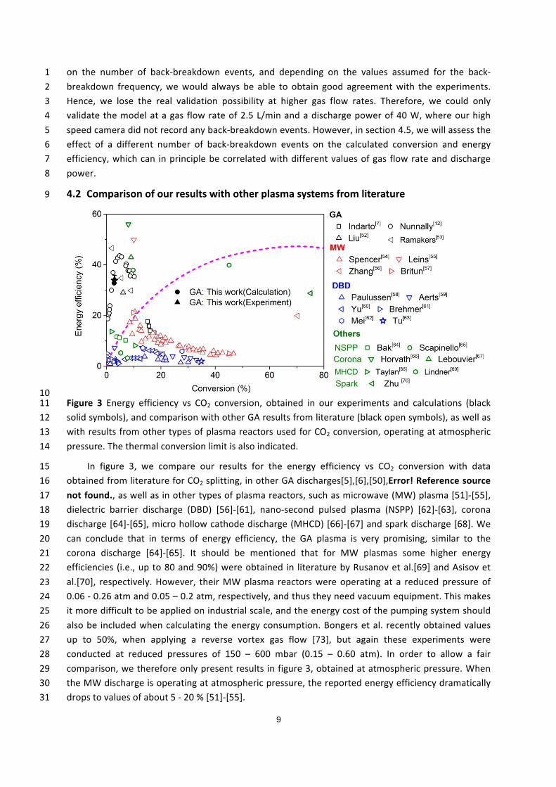
10Figure 3 Energy efficiency vs CO2 conversion, obtained in our experiments and calculations (black11solidsymbols),andcomparisonwithotherGAresultsfromliterature(blackopensymbols),aswellas12withresultsfromothertypesofplasmareactorsusedforCO2conversion,operatingatatmospheric13pressure.Thethermalconversionlimitisalsoindicated.14
In figure 3, we compare our results for the energy efficiency vs CO2 conversion with data15obtainedfromliteratureforCO2splitting,inotherGAdischarges[5],[6],[50],Error!Referencesource16notfound.,aswellasinothertypesofplasmareactors,suchasmicrowave(MW)plasma[51]-[55],17dielectric barrier discharge (DBD) [56]-[61], nano-second pulsed plasma (NSPP) [62]-[63], corona18discharge[64]-[65],microhollowcathodedischarge(MHCD)[66]-[67]andsparkdischarge[68].We19can conclude that in terms of energy efficiency, the GA plasma is very promising, similar to the20corona discharge [64]-[65]. It should be mentioned that for MW plasmas some higher energy21efficiencies (i.e.,upto80and90%)wereobtained in literaturebyRusanovetal.[69]andAsisovet22al.[70], respectively.However, theirMWplasma reactorswereoperatingat a reducedpressureof230.06-0.26atmand0.05–0.2atm,respectively,andthustheyneedvacuumequipment.Thismakes24itmoredifficulttobeappliedonindustrialscale,andtheenergycostofthepumpingsystemshould25alsobe includedwhencalculatingtheenergyconsumption.Bongersetal. recentlyobtainedvalues26up to 50%, when applying a reverse vortex gas flow [73], but again these experiments were27conducted at reduced pressures of 150 – 600 mbar (0.15 – 0.60 atm). In order to allow a fair28comparison,wethereforeonlypresentresults infigure3,obtainedatatmosphericpressure.When29theMWdischargeisoperatingatatmosphericpressure,thereportedenergyefficiencydramatically30dropstovaluesofabout5-20%[51]-[55].31

10
If we compare our results with those obtained in other GA reactors from literature, it is1importanttoexplainthatthereexistroughlytwodifferentreactordesigns.TheclassicalGAreactor,2whichisusedinthisstudy,typicallyconsistsoftwoplanedivergingelectrodesbetweenwhichthegas3flows. Incontrast, recentlya three-dimensionalGA reactor, consistingof cylindricalelectrodeswith4tangential gas inlet, leading toavortexgas flowconfiguration,hasbeendeveloped,also calledGA5plasmatron(GAP)[19].Indartoetal.[5]appliedaclassicalGAconfiguration,likeinourcase,andthey6obtainedahighestenergyefficiencyofaround17%,whichismuchlowerthanourcurrentwork.On7theotherhand,Nunnallyetal. [6], Liuetal. [50]andRamakersetal.Error!Reference sourcenot8found.usedavortexflowGAP,whichcanreachasomewhathigherconversionandenergyefficiency.9Thisreactordesignisindeedverypromising,becauseitcanbemoreeasilyimplementedinindustry10andthespecificgasflowconfigurationensuresthegastreatmenttobemoreuniform.Thisindicates11thatabetterdesignoftheclassicalGAreactor,toenhancethetreatedgasvolume,would improve12theconversionperformance,aswillbediscussedindetail insection4.5below.However, ingeneral13wecandeduce from figure3 that theGAplasmashowsaverygoodperformancewitha relatively14high energy efficiency. This is because the energy efficient vibrational excitation processes are15favoured,aswillberevealedinsection4.4below.16
Itisobviousfromfigure3thataDBDplasma[56]-[61]hasareasonableconversionbutaquite17lowenergyefficiency.Thisisduetothenon-idealoperatingconditions,astheelectrontemperature18is typically higher than in a GA (orMW) plasma [19],[72], and themechanism of CO2 conversion19involveschargedandelectronicallyexcitedspecies,andthusitislimitedbythehighenergycostfor20theformationofthesespecies.Thesameappliesforthenano-secondpulsedplasma(NSPP)[62]-[63]21which also has a rather lowenergy efficiency. The process capability of themicro hollow cathode22discharge(MHCD)[66]-[67] isvery limiteddueto itsverysmallvolume.Therefore, itgenerallyalso23exhibits a relatively low energy efficiency. The spark discharge [68] has a very high conversion,24becauseoftheveryhighenergyconsumption.Theenergyefficiencyisalsoquitehigh,butitislower25thanthethermalconversionprocess.Thismaybeattributedtothefact thatmostof theenergy is26spent on the gas heating and the energy exchange with the surroundings. In general, we can27concludethattheenergyefficiencyinourGAreactoratatmosphericpressureisbetterthantheDBD28plasma,microwaveplasma,nano-secondpulsedplasmaandmicrohollowcathodedischargeplasma,29andcomparabletothecoronadischarge[64]-[65].30
Finally,we also benchmark our results for theGA based CO2 conversion to the pure thermal31conversion process (see the calculationmethod for the latter in the supporting information). It is32clear that the CO2 conversion in our GA proceeds more energy efficient than pure thermal33conversion. This is because the energy in the thermal conversion is distributed over all degrees of34freedombasedontheequipartitionprincipleofenergy,andthusitisespeciallyspentongasheating35rather than on CO2 dissociation reactions. In contrast, our GA clearly operates in non-equilibrium36conditions,astheelectronshaveamuchhighertemperaturethanthegasitself(seeourcalculation37results in section 4.3 below). These highly energetic electrons induce different chemical reactions,38whichnormallydonotoccurattheconsideredgastemperateincaseofequilibriumconditions.39
Inspiteofthereasonableresultsobtainedalreadybytheglidingarc,theconversionshouldstill40be further improved, while maintaining the high energy efficiency. More specifically, if this low41conversioncouldnotbefurtherimproved,itwouldimplytheneedforoperatinginarecyclemode,42whichwouldmakethesystemhighlynon-effective.43

11
4.3 TypicalGAdischargecharacteristics1
InordertounderstandthetimebehavioroftheplasmacharacteristicsintheCO2GA,weplotin2figure4 theelectronnumberdensity,electrontemperature,gas temperature,aswellasof theCO3molar fraction distribution, at different moments in time, for a gas flow rate of 2.5 L/min and a4dischargepowerof40W.5
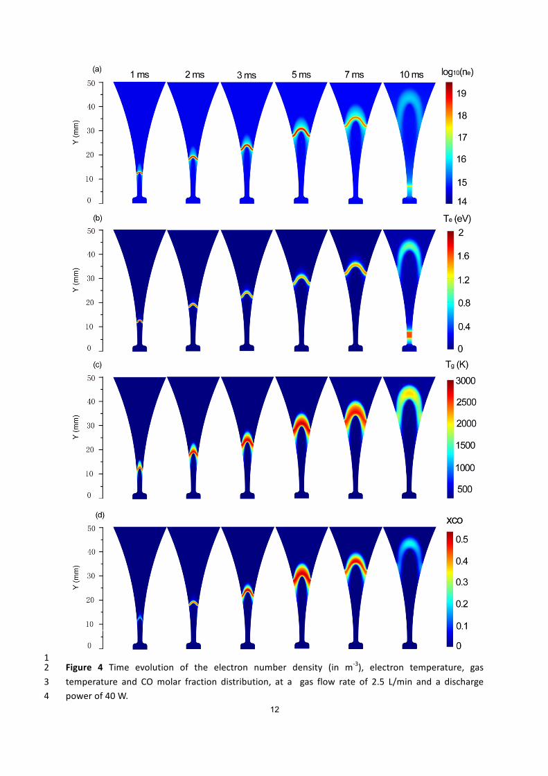
12
1Figure 4 Time evolution of the electron number density (in m-3), electron temperature, gas2temperature and COmolar fraction distribution, at a gas flow rate of 2.5 L/min and a discharge3powerof40W.4

13
Theresultsareplottedstartingfromt=1ms.Att=0ms,thesourcevoltageislargerthanthe1criticalbreakdownvoltagewithashortestgapseparationof2mm.Thedischargeignitiontakesplace,2becauseofapositivevalueofthenetelectrongeneration,yieldinganabruptincreaseoftheelectron3numberdensityduringtheelectricalbreakdown.Oncetheconductingchannelisestablished,thearc4travelsalongtheelectrodesasaresultofthegasflowdrag. Sincethegasvelocityhasamaximum5value at the discharge axis and gradually decreases to zero at the electrode surface, the arc root6movesatamuchslowervelocitycomparedtothearcbody.Thus,thearcgraduallybeginstobend7duetothegasblast.Themaximumelectronnumberdensityalsoincreasesduetotherisingvoltage8andhencedischargecurrent(seefigureS1inthesupportinginformation),tillapeakvalueisreached9at3.5ms(seefigure4(a)).Atlatertimes,thedischargecurrentdrop,andconsequently,theelectron10density follows the same trend till zero at t = 8.5ms,when the applied voltage reaches zero (see11figureS1). TheGAgraduallyextinguishesandentersa relaxation stage,where thevoltage is small12andnotenoughtosustain theGAdischarge.Thus, there isadecayingresidual lowdensityplasma13movingdownstreamwiththegasflow(seefigure4(a)).Shortlyaftert=8.5ms,theappliedvoltage14of the alternating current (AC) power source changes its polarity (see figure S1 of the supporting15information) and reaches again the critical breakdown voltage at the narrowest electrode gap16separationof2mm,wherearestrikeoccursbyestablishinganewconductingchannel.Itshouldbe17notedthatthere-ignitionoftheGAdoesnotexactlytakeplaceattheshortestgapseparation(Y=182.5mm),butatY=7.5mm. This isbecausethe localelectricfieldatY=7.5mmfirstreachesthe19critical breakdown field. This is in good agreement with our experiments, recorded by the digital20camera(seefigureS2ofthesupportinginformation).21
The rise and drop in electron number density during one GA discharge cycle results in an22enhanced and reduced Joule heating effect before and after t = 3.5 ms, respectively. The Joule23heating refers to the process by which the passage of an electric current through a conductive24medium produces heat and causes heating of the electrons. Correspondingly, the electron25temperature first increases and then decreases (see figure 4(b)). After t = 8.5 ms, the electron26temperature of the residual GA channel continuously decreases, because the electron number27densityandtheelectricenergystoredinthechanneldecayveryrapidly.Subsequently,theextremely28largereversepolarityvoltageimposedacrosstheelectrodesattheshortestelectrodegapleadsagain29toanincreaseoftheelectrontemperatureandhenceasubsequentbreakdownatthenewposition30ofY=7.5mm(seefigure4(b)).31
Oncethedischarge is ignited,theelectronscausevibrationalexcitationofCO2,andtheenergy32stored in the vibrationally excited states will partially be transferred to the gas by vibrational-33translational(V-T)relaxation.Indeed,atatmosphericpressure,thetypicalcharacteristictimeforV-T34relaxationinCO2isveryshort(around10-5s).Asaresult,thegastemperaturealsorisesasafunction35oftime,reachingamaximumvalueofabout2700Kataroundt=3.5ms,whentheappliedsource36voltage(Vsource=7200sin(2π50t+0.50))andthedischargecurrentreachtheirmaximum(seefigure374(c)). Subsequently, the gas temperature in the arc channel gradually decreases to around2000K38whenanewcyclestartsatt=10ms,becausethedischargepowerdecaysrapidlyintherelaxation39stagefrom8.5msto10ms.40
TheCOmolarfractionisobviouslyequaltozerobeforethearcisformed,butitstartsincreasing41graduallyasafunctionoftime,whenthevoltageandhencethedischargecurrentinthearcrise,up42toavalueof0.55att=3.5ms,indicatingthatCO2isgraduallyconvertedintoCO.Atlatertimes,the43
14
dischargecurrentandhencethedischargepowerstarttodrop,sotheCOmolarfractionwithinthe1arcchannelgraduallydecreasesuntilthearcisextinguished.ThisiscausedbyrecombinationofCO2andOintoCO2.Furthermore,newCO2gaswillcontinuouslybetransportedintothearcchannelby3bothdiffusionandconvection,whilethedissociationproductswillleavethedischargechannelbythe4sametransportmechanisms.ThisleadstoareductionofthemaximumlocalCOmolarfraction,asis5clearly indicated in figure4 (d).Note that theoverallCO2 conversion ismuch lower than the local6conversionof 80%,which corresponds to themaximumCOmolar fractionof 0.55 (andCO2molar7fractionof0.2;seebelow).ThisisbecausetheoverallCO2conversioniscalculatedfortheentiregas8passingthroughthereactor,integratedoverthetimeofoneGAcycle(i.e.,10ms),andthusnotonly9forthefractionofgaspassingthroughtheactivearcchannelatacertainmomentintime.10
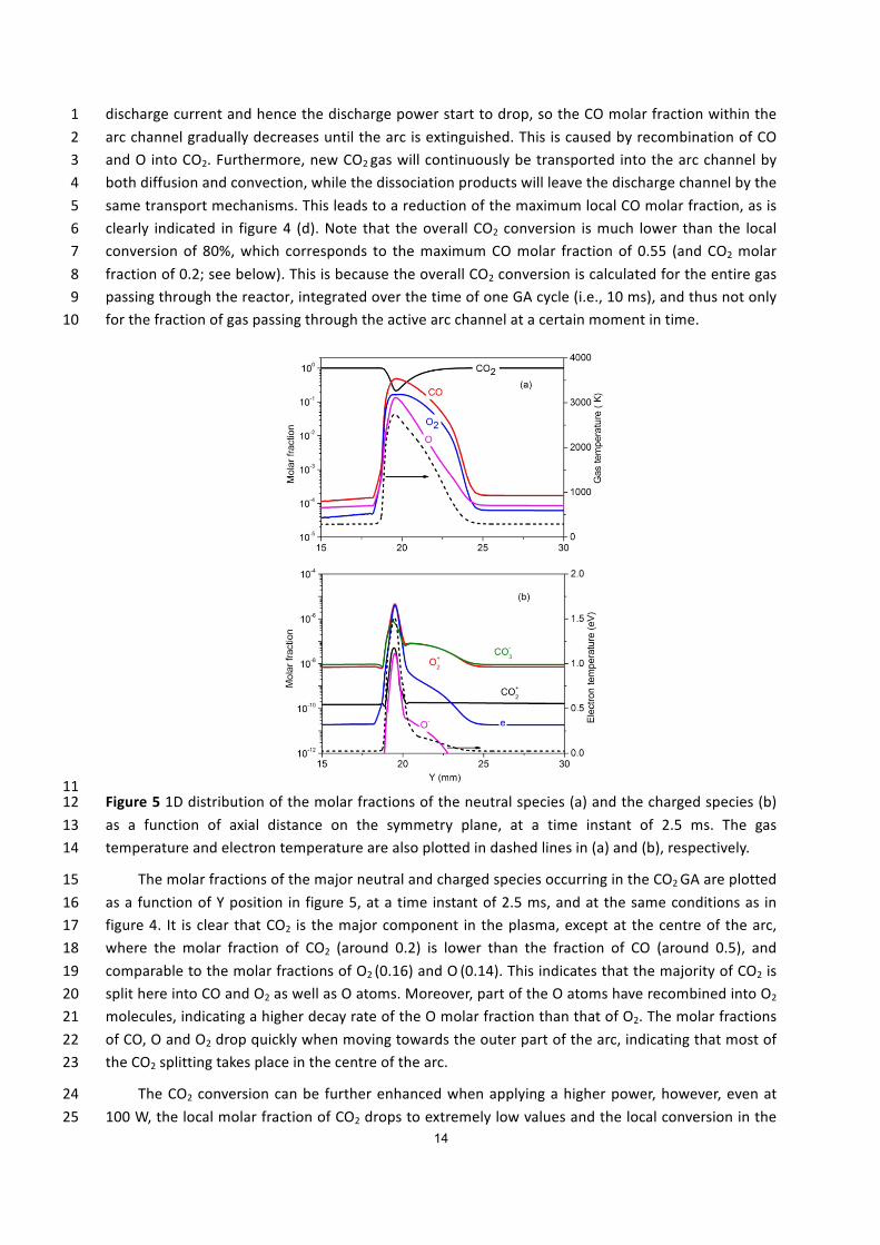
11Figure51Ddistributionofthemolarfractionsoftheneutralspecies(a)andthechargedspecies(b)12as a function of axial distance on the symmetry plane, at a time instant of 2.5 ms. The gas13temperatureandelectrontemperaturearealsoplottedindashedlinesin(a)and(b),respectively.14
ThemolarfractionsofthemajorneutralandchargedspeciesoccurringintheCO2GAareplotted15asafunctionofYposition infigure5,atatimeinstantof2.5ms,andatthesameconditionsas in16figure4. It isclear thatCO2 is themajorcomponent intheplasma,exceptat thecentreof thearc,17where the molar fraction of CO2 (around 0.2) is lower than the fraction of CO (around 0.5), and18comparabletothemolarfractionsofO2(0.16)andO(0.14).ThisindicatesthatthemajorityofCO2is19splithereintoCOandO2aswellasOatoms.Moreover,partoftheOatomshaverecombinedintoO220molecules,indicatingahigherdecayrateoftheOmolarfractionthanthatofO2.Themolarfractions21ofCO,OandO2dropquicklywhenmovingtowardstheouterpartofthearc,indicatingthatmostof22theCO2splittingtakesplaceinthecentreofthearc.23
TheCO2conversioncanbe furtherenhancedwhenapplyingahigherpower,however,evenat24100W,thelocalmolarfractionofCO2dropstoextremelylowvaluesandthelocalconversioninthe25
15
GA reaches almost 100 %. This limits the further improvement of GA based CO2 conversion.1Therefore, the conversion can only be further enhanced if we can providemore CO2 into the arc2centre,whileatthesametimeremovethedissociationproducts(COandO2)outofthearccentre.3Thiswillbefurtherdiscussedindetailinsection4.5.4
Themolarfractionsofthevariouschargedspeciesareatmaximum10-5,eveninthearccentre,5andtheyclearlydropuponlargerdistancefromthecentreofthearc.Alsotheelectronmolarfraction6isatmaximum10-5, indicatingthattheCO2plasmaisonlyweaklyionized,eveninthecentreofthe7arc.Themajorpositive ionsare the𝑂ai ions,while the𝐶𝑂j; ionsare themajornegative ions,and8theyareevenmoreimportant(althoughstillwithverylowmolarfractions)thantheelectrons,except9inthecentreofthearc.Thesetrendsareinagreementwithourpreviousfindingsobtainedbya1D10cylindricaldischargemodel,despitetheconsiderablenumberofapproximationsadoptedthere[41].11
Thegastemperatureandelectrontemperaturearealsoplottedinfigure5.Theybothreachtheir12maximuminthecentreofthearc,as is logical,andtheydropsignificantlyasafunctionofposition13from the arc centre. The electron temperature reaches amaximumof 1.5 eV (or 17,400 K) in the14centreofthearcatthetimeinstantof2.5ms,butitdropssignificantlyasafunctionofrisingdistance15fromthearccentreinthefirst0.5mm,followedbyaslowerdecaytothermalvaluesatadistanceof16about1.0mmfromthecentre.Thegastemperatureisatmaximumabout2700Kinthecentreofthe17arc. From the comparison between these temperatures, it is clear that the gliding arc is far from18thermalequilibrium,astheelectrontemperatureisabout6timeshigherthanthegastemperature.19As mentioned in section 4.1 above, a gas temperature up to around 2700 K and an electron20temperatureup to1.5eVcorrespondwell toexperimentaldata found in literature for lowcurrent21atmosphericpressureGAdischarges,althoughitshouldbementionedthatitisnoteasytocompare22differentGAsetupswithdifferentreactorgeometriesanddischargeconditions.23
4.4 CO2conversionmechanismsintheGA24
Inordertoevaluatewhichmechanismsarethemost important fortheCO2splitting intheGA25plasma, andhow they caneventuallybe further improved,we investigated thedominant reaction26pathwaysfortheformationandlossofCO2forthesameconditionsasinfigure4.Thereactionsare27listedintable3andtheirrelativecontributionstotheoverallCO2lossandformationarepresentedin28figure6.Thiskineticanalysiswasperformedby lookingatthetimeandvolumeintegratedratesof29thevariousprocessesforacompleteglidingcycleof10ms. Inthesupporting information,wealso30plot the temporal evolution of the most important loss and formation rates of CO2, obtained by31integratingthereactionratesovertheentirereactor(seefigureS4).32
Table3DominantCO2lossandformationreactions.33
Process Lossreaction Process FormationreactionL1v 𝑒 + 𝐶𝑂a(𝑣) → 𝑒 + 𝐶𝑂 + 𝑂
F1 𝐶𝑂 + 𝑂a → 𝐶𝑂a + 𝑂(a)
L1g 𝑒 + 𝐶𝑂a(𝑔) → 𝑒 + 𝐶𝑂 + 𝑂L2v 𝐶𝑂a(𝑣) + 𝑂 → 𝐶𝑂 + 𝑂a F2 𝐶𝑂 + 𝑂 + 𝑀 → 𝐶𝑂a + 𝑀L2g 𝐶𝑂a(𝑔) + 𝑂 → 𝐶𝑂 + 𝑂aL3v 𝐶𝑂a(𝑣) + 𝑀 → 𝐶𝑂 + 𝑂 + 𝑀 F3 𝐶𝑂 + 𝑂; → 𝑒 + 𝐶𝑂aL3g 𝐶𝑂a(𝑔) + 𝑀 → 𝐶𝑂 + 𝑂 + 𝑀L4v 𝐶𝑂a(𝑣) + 𝑂; + 𝑀 → 𝐶𝑂j; + 𝑀 L4g 𝐶𝑂a(𝑔) + 𝑂; + 𝑀 → 𝐶𝑂j; + 𝑀
(a) O2representsthesumofthegroundstateandthevibrationalstatesofmolecularoxygen.34

16
1Figure6Relativecontributionsof themost importantprocesses forCO2 loss (a)and formation (b).2Thereactionnumbers in thex-axiscorrespondto thenumbers in table3.Note thatonly the three3mainlossprocessesareillustrated,asthefourthprocess(L4v,L4g)contributesforlessthan0.1%.4
ThemostimportantprocessforCO2lossisthedissociationofvibrationallyexcitedstatesofCO25uponcollisionwithOatoms(L2v)witharelativecontributionofabout80%.Thesameprocess,but6upon collision of ground state CO2 with O atoms (L2g) has a relative contribution of 9.2 %.7Furthermore, the dissociation of vibrationally excited states of CO2upon collisionwith any neutral8species (M) also contributes for 7.3 % (L3v). The relative contribution of the same process, but9starting fromgroundstateCO2, isonly0.21%(L3g).Besides,electron impactdissociation fromthe10CO2 vibrational levels (L1v) and from the CO2 ground state (L1g) contribute for 2.6% and 0.70%,11respectively.Comparedwith theelectron impactdissociation reactions, theneutral reactionsupon12collisionwithOatomshavea lowerenergy requirement [19]andhencearemoreenergyefficient.13NotethatreactionsL2vandL2gareactually follow-upreactionsofreactionsL1vandL1g,astheO14atomthatreactsinreactionsL2vandL2gistheresultofCO2splitting,eitherbyreactionsL1vandL1g,15or reactions L3v and L3g.Nevertheless, once the firstO atomsare formeduponCO2 splitting, the16reactionsL2vandL2gcanoccurinparalleltotheseotherreactions,andthuswecanconsiderthem17separatelyinthisanalysis.18
Ourcalculationresults reveal that theCO2dissociationmainlyproceeds fromthevibrationally19excited levelsofCO2.The latterprovidemoreenergyefficientdissociation,becausethevibrational20energy can help overcome the activation energy barrier of the reaction and thus increase the21reaction rate constant [26]-[27]. This is consistent with experimental investigations in literature.22Indeed, experimentalwork for both adiverging electrodes gliding arc reactor [5] and a gliding arc23

17
plasmatron [6] shows that thepresenceof a very small quantity ofwater added intoCO2 greatly1reducesthepowerefficiencycomparedwithpureCO2atatmosphericpressure.Thisisexplainedby2thefactthatwatercansignificantlyreducethevibrationalexcitationofCO2molecules,becausethe3energyisabsorbedandquicklylostbywater.Basedonthis,Nunnallyetal.[6]concludedthatnon-4equilibriumvibrationalexcitationplaysthemajorroleduringCO2dissociationinaglidingarc.5
Additionally, there exist measurements in the literature, demonstrating that the vibrational6temperature in the gliding arc is higher than the gas temperature, even at atmospheric pressure,7although we cannot validate our model by direct comparison, as experimental data for the8vibrational temperature inpureCO2 inclassicalglidingarc reactorsdonotyetexist.However, ina9non-equilibriumglidingarc"tornado"dischargeusingCO2dopedwith1%N2ataflowrateof10lpm10and a power of 200 W, Nunnally et al. [49] estimated the vibrational temperature to be11approximately 6000 K at atmospheric pressure, by comparing the theoretical and experimentally12measuredspectrafortheN2system,andthisvalueismuchhigherthanthereportedrotationalgas13temperatureof2700K±50K.Therefore,theseexperimentalresultssupportourmodellingresults.14
Someofthereactionsplottedinfigure6(a)alsooccurintheoppositedirection,hence,besides15dissociationofCO2,therecombinationofCOwithO2,Oand𝑂;ionsalsotakesplaceintheGA,giving16rise to the formation of CO2 again and yielding a lower net conversion of CO2. The recombination17reactionofCOwithO2molecules(F1,i.e.,theoppositeofL2)isthepredominantproductionprocess18of CO2, with a relative contribution to the overall CO2 formation amounting to 94 %. The19recombinationreactionofCOwithOatoms(F2,i.e.,theoppositeofL3)hasarelativecontributionof205.2%,whiletherecombinationofCOwith𝑂;ions(F3)onlycontributesfor0.068%.Otherreactions21playanegligibleroletowardsCO2formation(<0.05%).22
Note that the reverse reactions, especially the recombination of COwith O2molecules, have23onlyslightlylowerratesthantheratesofthemostimportantlossprocesses,asdepictedinfigureS424in the supporting information. Therefore, these reactions have a detrimental effect on theoverall25CO2conversion. Indeed,when the rates of these reactionswould becomeeven larger, theywould26inhibit further CO2dissociation. This happenswhen a considerable fractionof theCO2molecules is27already converted into CO and O/O2, and especially at high gas temperature in the arc. When28comparingthetotallossofCO2,integratedovertheentirearcandthewholeglidingcycle,withthe29totalformationofCO2,weobtainvaluesof3.8x1018vs3.5x1018attheconditionsunderstudy.Thus,30itisclearthatabout92%oftheCO2convertedintheGA,willbeformedagain,sothenetconversion31ofCO2intoCOismuchsmallerthantheinitiallossofCO2.Therefore,therecombinationofCOwith32O2backintoCO2isclearlyalimitingfactor,whichaffectsthefurtherimprovementofGAbasedCO233conversionanditsenergyefficiency.Thiswillbediscussedinthenextsection.34
4.5 HowtoimprovetheCO2conversionandenergyefficiencyintheGA?35
From previous section, we can clearly identify the limiting factors for energy efficient CO236conversionintheGA.Therefore,inthissection,wewillproposesolutionsonhowtofurtherimprove37theperformanceoftheGAforenergyefficientCO2conversion.Firstwewilldiscusstheroleofthe38vibrationallevelsinenergyefficientCO2conversion.Subsequently,wewilllookinmoredetailatthe39recombinationofCOwithO2,whichcontributesmostlytotheCO2formationattheconditionsunder40study.Finally,wewillelaborateonsomewaystoincreasingthevelocitydifferencebetweentheGA41andthegasflow,whichcanincreasethefractionofCO2thatcanbeprocessedbythearc,andhence42improvetheconversion.43
18
4.5.1 Promotingthevibrationalkinetics1
It is clear that non-equilibrium vibrational excitation of CO2 promotes energy efficient2dissociation in theGA.This isalsoconsistentwithexperimental investigations in literature [6].Our3resultsindicatethatthepopulationofthesymmetricmodelevelsandthelowerasymmetricstretch4modelevelsismuchhigherthanthatofthehigherasymmetricmodelevels.Therefore,theselower5vibrationallyexcitedlevelsmostlyaccountforthetotalCO2conversion,althoughthereisstillsome6overpopulation for the higher levels. The reason why especially the lower vibrational levels7contribute to the CO2 conversion is because the vibrational energy distribution function tends to8becomemorethermalizedathighgastemperature[73].Indeed,theenergyexchangeuponcollision9betweenvibrationallevelsandgroundstatemolecules,whichdepopulatesthevibrationallevels,i.e.,10so-called VT relaxation, increases with gas temperature. Therefore, we should look for ways of11inhibiting the VT relaxation process to increase the degree of overpopulation of the higher12asymmetricmodelevels.13
A recent kineticmodelling ofmicrowave plasma based CO2 conversion has shown that lower14pressures,lowergastemperatureandhigherpowerdensities(atleastforpressuresbelow300mbar)15lead to more vibrational excitation, which is beneficial for the conversion [73]. However, our GA16operates at atmospheric pressure, which is more convenient for industrial applications, so the17solutionsof reducing thegaspressureand increasing thepowerdensity (whichonlyhasbeneficial18effect at a pressure below 300 mbar [73]) are not practical. Therefore, we believe that the gas19temperature should be reduced, to inhibit theVT relaxation, and thus to promote the role of the20highervibrationallevels,andhencetheconversionandenergyefficiency.Inthisrespect,enhancing21themixingbetweentheGAandthecoldgascanhelptorealizethisgoal,whichwasclearlyindicated22by our previous modelling for a 1D gliding arc [41] and by experimental work [6]. Furthermore,23reducingthegastemperaturewillalsoresultinaloweringoftherecombinationreactions,thusalso24improvingtheoverallCO2conversion(seenextsection).Ontheotherhand,itwillalsoleadtoadrop25inthedissociationrateconstantsbyneutralparticlecollisions,andthishasadetrimentaleffecton26theconversion.Therefore,anoptimizedgastemperatureshouldexistforGAbasedCO2conversion,27where thebeneficialeffectofa lower temperature,dueto (i)amorepronouncednon-equilibrium28populationofthehighlyexcitedvibrationallevels,and(ii)lowerrecombinationratesofCObackinto29CO2, exceeds the detrimental effect by the lower dissociation rate constants of dissociation upon30collision with neutral particles. Finding out this optimal temperature is, however, not so31straightforwardwithour2Dmodel,asthelatterself-consistentlycalculatesthegastemperatureand32it is not an input in themodel. For this purpose, a 0Dmodel,where the gas temperature can be33introducedasaninputparameter,couldbemoresuitable[40].34
Besides,becauseelectron impactvibrationalexcitationofCO2 ismainly importantforreduced35electricfieldvalues(i.e.,ratioofelectricfieldovergasdensity)below80Td[72](where1Td=10-2136V/m2),weshouldtargettoactivelytunethereducedelectricfieldtothesevalues,byoptimizingthe37reactor electrical operating parameters. Finally, increasing the electron number density will also38promote thevibrationalexcitationand thus selectivelydeliverenergy to thismostenergyefficient39CO2dissociationpathway. Ithasbeen reported in literature [66] thataddingnoblegases, suchas40argon, to CO2would improve the CO2 conversion and energy efficiency by increasing the electron41numberdensity,becauseargonhasalowerbreakdownvoltagethanCO2.42
4.5.2 ReducingtherecombinationofCOwithO243

19
1Figure7Effectofdifferentratecoefficientsoftherecombinationreaction(CO+O2→CO2+O)onthe2calculatednetlossrateofCO2,integratedovertheentirereactorvolume,atthesameconditionsasin3figure4.4
It is clear from section 4.4 that the recombination reaction (F1), i.e., CO + O2→ CO2 + O, is5mainly limiting the CO2 conversion and energy efficiency. In our model, we adopted the rate6coefficient as proposed by Fridman [19]. However, to evaluate the effect of this recombination7reactionontheoverallCO2conversion,wehaveperformedsomefurthersimulationsinwhich(i)we8reduced the rate coefficient of this reaction by 50%, and (ii) we completely removed this9recombinationreactionfromthemodel,asindicatedinthelegendoffigure7.10
It isobvious from figure7 thata lower rate coefficientof the recombination reactionyieldsa11highernetCO2lossrate.TheCOconcentrationwithintheGAchannel,andhencetheinfluenceofthe12recombination reactionon theCO2 formation, isminor till t=1.7ms.Asa result, thedifferent rate13coefficients have a negligible effect on the net loss rate of CO2 up to 1.7ms. Upon increasing CO14concentration,thedifferentratecoefficientsdocausesomedeviationinthecalculatednetlossrates15ofCO2. After t=7.5ms, the formation rateofCO2iseven larger than the loss rate for k1andk2,16leading to a negative value of the net CO2 splitting rate. Of course, integrated over the entire GA17cycle, the overall CO2 loss (or conversion) rate is still positive, but it is greatly reduceddue to this18importantbackward(recombination)reaction.19

20
1Figure8Effectofusingdifferentratecoefficientsoftherecombinationreaction(CO+O2→CO2+O)2onthecalculatedCO2conversion(a)andenergyefficiency(b),forthesameconditionsasinfigure7.3Seelegendoffigure7forthevaluesofk1,k2andk3.4
Figure8showstheconversionandenergyefficiency,calculatedwiththeoriginalratecoefficient5(k1) [19], incomparisonwiththeresultsobtainedwhenthisratecoefficient isdividedby2 (k2),as6wellaswhentherecombinationreactionisremovedfromthemodel(k3).Theconversionandenergy7efficiency increaseonly slightlywhen the recombination ratecoefficient isdividedby2,while they8rise from 2.8 % to 4.0 %, and from 33 % to 47 %, respectively, by removing the recombination9reaction (CO + O2→ CO2 + O) from the model. Although the conversion is still low, the energy10efficiency rises significantly. This clearly indicates that reducing the recombinationofCOwithO2 is11quitepromisingtoenhancetheCO2conversionand(especially)theenergyefficiency.12
To achieve this objective, we suggest to apply possible scavengers, catalysts or separation13membranes,inordertoremovetheO2molecules[31].Theseareonlysuggestions,andtheyshould14of course be experimentally explored to evaluate the possibilities. On the other hand, the15combinationofasolidoxideelectrolysercellwithaplasmaset-upwasalreadyillustratedin[74]tobe16beneficialfortheCO2conversion,anditworksaccordingtothesameprinciple.Inthisway,thelocal17concentration ofO2moleculeswithin the arc channel, and hence the net formation of CO2 by the18recombinationreaction(CO+O2→CO2+O),couldbereduced,becausethereisnotenoughreactant19(O2)availableforthebackwardreactionfromCOintoCO2(F1).20
H2orCH4couldactaspossiblescavengersforatomicoxygen,formingH2O.Thispossibilitywas21alreadyillustratedtobebeneficialforOtrappinginliterature,basedonacombinedplasmachemical22
21
kineticsmodelandexperimentsforCO2conversioninanothertypeofplasma[75].ThetrappingofO1atomsmightbeabletopromotetheCO2conversionby(i) inhibitingtherecombinationreactionF22[40], and (ii) by avoiding the formation of O2, which will inhibit the recombination reaction F1.3Experiments in literature have indeed revealed that the addition of H2 or CH4 in aGA reactor can4improve the conversion of CO2 [6],[54], but the enhanced conversion of CO2 cannot be simply, or5entirely, attributed to the inhibited recombination reactions. This is because the H atoms or CHx6radicalsproducedbyH2orCH4dissociationcanalsocontribute toCO2dissociation. Moreover, the7removalofOatomswillalsoinhibitthedominantmechanismofCO2splitting,i.e.thedissociationof8CO2uponcollisionwithOatoms(L2v,L2g)andthusitmightalsoexhibitanegativeeffectonfurther9improving the CO2 conversion. Therefore, the reason why adding H2 or CH4 promotes the CO210conversion isnotnecessarilyattributedtotheirscavengingrole inconsumingtheOatoms. Indeed,11thedirectinvolvementinCO2splittingbythereversedwatergasshiftreaction(CO2+H2→CO+H2O)12hasbeenverifiedtobeaveryimportantpathforCO2splittingintoCOwhenCH4[54]orH2[6]isadded13into a CO2 GA plasma.Moreover, the addition of H2 or CH4 can increase the electron density by14inhibitingelectronattachmenttoO2(whichisanelectronegativegas),andthiscanalsocontributeto15ahigherCO2conversion.16
The ideaof using a catalystwith a high surface interaction forO atoms to recombine intoO217[76]orforO2adsorptionisprobablynotveryeffective,becausetheO2moleculeswouldbereleased18backtotheplasmaphaseandagainundergorecombinationwithCO. Incontrast,amoreadvanced19catalyticprocesswouldbeanalternativeformofchemicallooping,inwhichtheOorO2iscapturedin20theplasmaset-upandthenusedasoxidizingagentinasecondset-up[77]-[78].However,thisisonly21aconcept,andhasnotbedemonstratedyetforaGAreactor.22
The third method, based on separation membrane technology, would transport the O223molecules(orOatoms)awayfromthereactionmixture.Forexample,bycombinationofasolidoxide24electrolysercellwithaplasmaset-up,Tagawaetal.[74]andMorietal.[79]-[80]haveobservedan25increasingCO2conversionbyplacinganO2trappingmembraneintoaCO2/CH4orCO2discharge, in26ordertoseparateO2fromthereactionmixture.27
Besides the effect of possible scavengers, catalysts ormembranes to remove the oxygen, as28mentioned above, we believe that the recombination of CO with O2 could also be avoided or29minimizedbyprovidingeffectivequenchingofthehightemperature inthearczone,duetomixing30withcoldgasatveryfastcoolingrates.Thiscouldbeespeciallybeneficial intherelaxationstageof31theGA (around 8ms)when the discharge current is low, and the CO2 loss rate isminor, but the32recombinationrateofCOwithO2isstillverylargeduetotheveryhighgastemperature,leadingto33netCO2 formation. Indeed,aneffectivequenchingof the residualplasma temperaturecanhelp to34decreasetherecombinationreactionrateand inhibittheCO2formation inthisstage, leadingtoan35improved conversion and energy efficiency. We believe that such a quenching of the plasma36temperature could be realized by improving the reactor geometry and/or optimizing the flow37conditions,butfurtherstudiesareneededtoelaborateonthesesolutions.38
4.5.3 Increasing the CO2 fraction to be treated by the arc due to a velocity difference39betweenGAandgasflow40
BesidespromotingthevibrationalkineticsandreducingtherecombinationreactionofCOinto41CO2,anotherwaytoimprovetheCO2conversionwouldbetoenhancetheCO2fractiontobetreated42

22
by thearc,bybettermixingof theGAand thecoldgas flow.This canbe realizedwhen there isa1velocity difference between the GA and the gas flow. Several experimental studies indeed have2shownthatthearcglidingvelocitycanbeslightlylowerthanthegasvelocity[14],[33].Wepresent3heresomesimulationresults,showingthattherecanindeedbea(small)differencebetweenthearc4andgasflowvelocity.Wecandistinguishtwodifferentwaystorealizethis.5
(1) Smoothvelocitydifferenceduetothearcbending6
7Figure92Ddistributionoftheelectronnumberdensity(left,inm-3)andreducedelectricfield(right,8in Td) at a time instant of 2.5ms for the same conditions as in figure 4. The black and red lines9indicate the position of the arc center and of the maximum reduced electric field, respectively,10showingthattheyareseparated, leadingtoextra ionizationdownstreamthearc inthecentre,and11consequentlytoslowingdownofthearcmovement.12
Thefirstpossiblereasonforalowerarcvelocityvsgasflowvelocityisrelatedtothearcbending,13andthustheexistenceofzoneswithincreasedelectricfieldoutsidethearccentre.Thelatterindeed14leadstoaseparationofthearccentre(withthemaximumelectronnumberdensity)andtheposition15withmaximumreducedelectricfield,aspresentedinfigure9.Thisiscausedbythefactthatinthe16symmetryplane,whenthearcishighlybended,somepartsofthearcinthedownstreamregionof17thearc centre arepositioned closer toeachother. This increases theelectric field strength in this18regionandcausesagradualionizationofthegasinthedownstreamregion.Thelatterwillresultina19slightlylowerarcvelocitycomparedtothegasvelocity.Likewise,nearthewalls(cathodeandanode),20the maximum reduced electric field, and hence the gradual ionisation, appears in the upstream21regionofthearccentre,whichresultsinaslightlyhigherarcvelocitythanthegasvelocity.Thus,the22GAmoves a bit slower than the gas flow in the central part of the reactor and a bit faster in the23regionsnearthewalls.Att=2.5ms,ourcalculationpredictaGAvelocityof5.9m/s inthecentre,24comparedtoagasflowvelocityof7.4m/s.Theratioofgasvelocitytoarcvelocityisthus1.2,which25isinreasonableagreementwithexperiments[14],[33].26
Wehavealsoperformedcalculationsathighergasflowvelocity,andtheresultsshowthatthis27leadstoanincreasedvelocitydifferencebetweenthearcandgasflow.Forexample,withthesame28gasflowrateof2.5L/min,assumingtheflowpassingthroughachannelwithdepthof1mm,whichis29onlyhalfofthevalueinourstandardmodel,thegasflowvelocityatthesametimeinstantt=2.5ms30wascalculatedtobe8.3m/s,withaGAvelocityof5.8m/s,thusyieldingaratioofgasvelocityvsarc31
23
velocityof1.4.ThisclearlyshowsthatthevelocitydifferencebetweenGAandgasflowwillbehigher1forhighergasflowvelocities,whichisalsoreportedinexperiments[14],[33].Correspondingly,our2calculatedconversionincreasesfrom2.78%to4.4%,althoughtheenergyefficiencyonlyincreases3from 32.8 % to 34 %. Although this is an artificial method, we can show in this way that the4treatment capacity can be enlarged by increasing the local gas velocity and hence the relative5velocitybetweengasflowandGA.Increasingthelocalgasvelocitycanberealizedbymodifyingthe6reactorsetupandhencethe flowconfigurationata fixedgas flowrate, forexamplebyshortening7thenarrowestgapseparationofbothelectrodes[40]orbyreducingthedistancebetweenthenozzle8exitand the reactor [81]orbydecreasing thenozzle internaldiameter [82]. Indeed, following such 9methods, increased conversions were reached experimentally [40], [81] and [82]. However,we should10alsomentionthatsimplyadjustingtheseparametersisnotaproperwaytoenhancethetreatment11capacity of the GA reactor, because itmight give rise to an extreme increase in the gas velocity,12whichmay greatly reduce the effective residence timeof CO2 in theGA volume. This is of course13detrimentalfortheCO2conversion.Moreover,thehighgasvelocitywillbringastrongcoolingeffect14andhencealowergastemperature;thelattercanbebeneficial(topromotethevibrationalkinetics15and/or reduce the recombination reactions), but it may also be detrimental (due to the reduced16dissociation reaction rate constant), aswe discussed in section 4.5.1 above. Therefore, the above17mentioned operating parameters should be optimized in a suitable range, to guarantee an18improvementinconversionandenergyefficiency[83].19
(2) Suddenvelocitydifferenceduetoback-breakdownevents20
BesidesthesmoothreductioninGAvelocityexplainedabove,anotherreasonforthelowerarc21velocityvsgasflowvelocityisrelatedtotheinstabilitiesofthearcandtosecondarybreakdowns,also22calledback-breakdown,causingareductioninarclength[84].23
The back-breakdown phenomena, which result in a fast shortening of the arc as a result of24breakdownbetweendifferentpartsofthearc(insteadofbetweentheelectrodes)oftentakeplacein25aGA,especiallyathighergasflowrates,asalsomentionedinsection4.1.Theseshortcutseffectively26appearasalagofthearcvelocitycomparedtothegasflowandcouldbeanefficientmechanismfor27thetreatmentofalargergasfraction.Asexplainedattheendofsection4.1,thiseffectisnottaken28intoaccountinprevioussections,becauseatthegasflowrateof2.5L/min,ourhighspeedcamera29didnotrecordanyback-breakdownevents.30
31Figure10Back-breakdowneventrecordedbythehighspeedcameraataflowrateof5L/min(500032frames/s,exposuretimeof50μs,electrodethroatof2.0mm)33
24
Figure10illustratesaback-breakdownevent,recordedbythehighspeedcameraataflowrate1of5L/min.Indeed,atahighgasflowrate(above2.5L/min),theGAdischargeisunstableandithasa2ratherirregularshape.WhensomepartsoftheGA(seepointsAandBinfigure10)getclosertoeach3other,theelectricfieldthereincreases.Oncethepotentialdifferencebetweenthesetwoparts,and4hence the local electric field, exceeds the critical breakdown electric field [85], a new discharge5channel is established (seemiddle panel) and the old discharge channel disappears very fast. This6causesadropintheGAvelocityascomparedtothegasflowvelocity.7
Although several experiments [36],[84] have been performed to study the back-breakdown8events, it is not straightforward to establish a self-consistent back-breakdown model, since this9behaviourismostlystochasticbynatureandthearcinstabilitiesarenotwelldefined.Toinvestigate10here the influence of the back-breakdown events on the CO2 conversion, we have initiated this11processbyestablishinganartificialplasmachannel,whichistriggeredonaregularorirregularbasis12withrespecttothearcpathortime, i.e.,aftereverycertaindistanceorperiod.Detailsonhowthe13back-breakdownmodelisestablishedcanbefoundin[38],aswellasinthesupportinginformation14ofourpaper.15
16
17Figure11Effectoftheback-breakdowneventsontheCO2conversionandenergyefficiencyatagas18flowrateof5.0L/min,fordifferentcases,i.e.,withoutbackbreakdown(1);oneback-breakdownat519ms(2);atwoback-breakdowns,at5msand6ms(3);threeback-breakdowns,at5ms,6msand7ms20(4);andfiveback-breakdowns,at5ms,5.5ms,6ms,6.5msand7ms(5).21
Figure11illustratestheeffectoftheback-breakdowneventsonthecalculatedconversionand22energy efficiency. The power needed to initiate the back-breakdown events is included in the23determination of the total plasma power and hence in the SEI value in Eq. (3), as well as the24
25
calculation of the energy efficiency in Eq. (4) (see section 2). It is clear that the back-breakdown1events yield an improved CO2conversion and energy efficiency, compared with the case without2back-breakdown, because a larger fraction of CO2 is treated by the newly established discharge3channel. This also explains why a larger number of back-breakdown events can enhance the CO24conversionandenergyefficiency(seecases2,3,4and5).Moreover,moreback-breakdownevents5alsoresultinaloweroverallgastemperature,asisclearfromfigureS7ofthesupportinginformation,6becausetheheatisnowspreadoveralargerdomainandnotonlywithintheinitialarcchannel.This7lowergastemperaturecanhavebeneficialordetrimentaleffectsontheoverallCO2conversion,as8explainedabove.9
As discussed above, the occurrence of the back-breakdown events is closely linked with two10factors,i.e.thearcinstabilitiesandasufficientlyhigharcvoltagedrop.Theformerleadstoarather11irregular arc shape and a non-stable discharge, increasing the probability of a closer interaction12betweentwoseparatedpartsoftheGA.Thelattercanensureahighenoughelectricfieldbetween13thetwoseparatedpartsofthearc,to igniteanewdischargechannel. Inordertosatisfythesetwo14essential requirements, besides increasing the gas flow rate, the gas flow velocity must also be15increasedbymodifying the reactor setup andhence the flow configurationunder a fixed gas flow16rate,asdiscussedabove.17
4.5.4 Summaryoftheproposedimprovements18
19Figure12EnergyefficiencyvsCO2conversioninourGAreactor,asobtainedbyourexperimentsand20calculated by our model, for the standard conditions (indicated with the oval), as well as several21improvements as predictedby themodel, by either (i) reducing the recombination rate coefficient22fromk1tok2(a)andk3(b)(cf.figure7),or(ii)enhancingthetreatedCO2fraction,byincreasingthe23numberofback-breakdownevents,from1(c)to2(d)to3(e)to5(f),applicableatahighergasflow24rate (5 L/min),or (iii)by increasing the localgasvelocityat the samegas flow rate,due to reactor25inletmodifications,leadingtoahighervelocityratiobetweengasflowandGA(g).26
Finally, in figure12,weschematically summarize the improvement in theCO2conversionand27energyefficiency,asproposedandpredictedbyourmodel.TheCO2conversionandenergyefficiency28areabout2.78%and32.8%(calculated)or2.90%and34.3%(measured)atthestandardconditions29investigated,i.e.,agasflowrateof2.5L/minandaplasmapowerof40W,correspondingtoaSEIof300.25eV/molecule.However,thesevaluescanbeimprovedaccordingtothemodelpredictions,upto31

26
aconversionofnearly4%andacorrespondingenergyefficiencyof47%(seepointb)byinhibiting1therecombinationreactionofCOwithO2.Furthermore,ifthegasfractionthatcanpassthroughthe2arc zone could be enhanced, for instance by modifying the reactor setup and hence the flow3configuration to realize a higher relative velocity between arc and gas flow, the conversion and4energyefficiencyarepredictedtoincreaseto4.4%and34%,respectively(seepointg).Finally,the5occurrenceofback-breakdownevents,whichinduceanabruptdifferenceingasflowvelocityandGA6velocity, in caseof a gas flow rateof5 L/min (where theback-breakdownevents indeed can take7place),canalsohelptoincreasetheconversion,althoughtheeffectseemstoberatherlimited,with8amaximumconversionupto2.6%,whiletheenergyefficiencywouldincreaseupto41%(seepoint9f).10
Theproposedsolutionsyieldsomeimprovementinconversionandenergyefficiency,butthese11modelpredictionsstillneedtobeverifiedbyexperiments.Wehopethatourmodelpredictionswill12inspireexperimentalresearcherstotryoutthesemodifications.Furthermore,theimprovementsare13probablystilltoolimitedforindustrialapplicationoftheGAforCO2conversion.Indeed,althoughthe14energyefficiencyisquitegood,theconversionisstillverylimited.Hence,moredrasticmodifications15would be needed, e.g., in the gas flow pattern or the source design, to significantly increase the16fractionofgasthatcanpassthroughthearc.Onepossiblesuggestionwouldbethereversevortex17flowglidingarc,whichisbasedoncylindricalelectrodes,andwhichallowsalargerfractionofthegas18to pass through the arc, yielding higher CO2 conversions, as demonstrated by [6], [50] and Error!19Referencesourcenotfound..20
2 Conclusions21
In this work we studied the CO2 conversion in a GA plasma, by means of a combined22experimental and 2D modelling approach. We compared our measured and calculated CO223conversionandcorrespondingenergyefficiency,aswellas theelectronnumberdensity in thearc,24andobtainedreasonableagreement.Thisindicatesthatourmodelcanprovidearealisticpictureof25theplasma chemistry and canbeused to elucidate theunderlyingmechanisms and thedominant26reactionpathwaysfortheGAbasedCO2conversion.27
We presented the typical arc plasma characteristics, such as the electron number density,28electrontemperatureandgastemperature,aswelltheCOmolarfraction,foroneentirearcgliding29cycle,ascalculatedbyourmodel.TheseresultsclearlyshowthattheGAplasmahasastrongnon-30equilibriumcharacter,becausetheelectrontemperature ismuchhigherthanthegastemperature,31andthehighlyenergeticelectronscaninduceseveraldifferentchemicalreactions.Thisexplainsthe32betterperformanceoftheGAforCO2conversion,yieldingamuchhigherenergyefficiencyforafixed33valueof theconversion, thanpure thermalconversion, forwhich theenergy isdistributedoverall34degreesoffreedom,includingthosenoteffectivefortheCO2conversion.35
We also performed a chemical kinetics analysis of themodelling results,which enables us to36identify the important species and reactions playing a role in the CO2 splitting, i.e., the main37productionandlosspathwaysofCO2.Thisallowsustogainsufficientinsightintotheentireprocess,38andto identify the limiting factors forCO2conversion,and thus toproposesolutions for improving39theCO2 conversion.Ourmodelpredicts that themost importantprocess forCO2 conversion is the40dissociationofvibrationallyexcitedstatesofCO2uponcollisionwithOatoms,indicatingthattheCO241vibrational levels significantly contribute to the CO2dissociation. This can explain the good energy42efficiencyofCO2conversioninaGAplasma,ascomparedtosomeotherplasmatypes.43

27
Webelievethat,whenitispossibletoactivelytunethereducedelectricfield(i.e.,E/nratio)in1theplasma,byoptimizingthereactorelectricaloperatingparameters,orwhenwecanincreasethe2electron number density, as well as inhibit the VT relaxation processes by decreasing the gas3temperature,weshouldbeabletofurtherpromotethevibrationalexcitationandselectivelydeliver4energy to the CO2 dissociation via this energy efficient pathway. This should lead to some further5improvementintheenergyefficiencyofCO2conversionintheGA.6
Furthermore,ourcalculationshowsthatthereversereactions,especiallytherecombinationof7COwithO2molecules(andtoalowerextentwithOatoms),haveanon-negligiblerate,comparedto8theCO2lossrate.Therefore,thesereactionshaveadetrimentaleffectontheoverallCO2conversion.9Thus,inordertofurtherimprovetheCO2conversion,thereversionreactionsshouldbeinhibitedor10at least reduced. We clearly demonstrate this by running the model with different reaction rate11coefficients for recombination, and when this recombination reaction is entirely removed, the12calculated CO2 conversion and energy efficiency rise from 2.8 % and 33 %, to 4.0 % and 47 %,13respectively.14
Finally,oursimulationshowsthat themolar fractionofCO2withinthearccenter isvery low,15indicatingthatthelocalCO2conversionisnearlycomplete,butbecausethefractionoftreatedCO216withinthearcisverylimited,theoverallCO2conversionisalsolimited.Therefore,weshouldlookfor17waystoincreasetheCO2fractiontobetreatedbythearc,inordertofurtherimprovetheGAbased18CO2 conversion. Increasing this treated gas fraction can be realized when there is a velocity19differencebetweentheGAandthegasflow,sothatnewfractionsoftheCO2gascanpassthrough20thearc,whiletheconvertedfraction(i.e.,CO,OandO2)willleavetheactivearcregion,beforeitcan21recombine back into CO2. We therefore discuss possible ways of increasing the relative velocity22betweenGAandgasflow.Thefirstwaytorealizethisisbyincreasingthelocalgasvelocitywithout23changing the gas flow rate, for instance by modifying the reactor setup and hence the flow24configuration. Indeed, at ahighgas velocity, there is a largerdifferencebetweenGAandgas flow25velocity due to some ionization downstream the arc channel, slowing down the arc movement.26Additionally, theoccurrenceofback-breakdownevents, creatingnewconductingarcchannels,will27alsocauseadifferencebetweenGAandgasflowvelocity,sowealsoinvestigatedtheeffectofthese28back-breakdown events on the calculated CO2conversion and energy efficiency. Our calculations29clearlyindicatethattheback-breakdownevents,whichgenerallytakeplaceatahighgasflowrate,30canhelptofurtherincreasetheCO2conversionandenergyefficiency.31
This study isof great interest forGAbasedCO2 conversion, aswewereable toelucidate the32mainunderlyingmechanismsandchemicalreactionsoftheconversionprocessbymeansofamodel33thatwasvalidatedbyexperiments. Ingeneral,weillustratedthatGAbasedCO2conversionisquite34promising,whencomparedwiththeclassicalthermalCO2conversionprocess,aswellaswithother35plasmatypes.This isattributedto itsnon-equilibriumcharacter,promotingthevibrationalkinetics.36However, we believe there is still room for improvement. Indeed, we could identify the limiting37factorsoftheCO2conversionintheGA,andthusproposesolutionsonhowtofurtherimprovethe38performance.39
Acknowledgements40
This research was supported by the European Marie Skłodowska-Curie Individual Fellowship41“GlidArc”withinHorizon2020 (GrantNo.657304)andby theFWOproject (grantG.0383.16N).The42
28
support of this experimental work by the EPSRC CO2Chem Seedcorn Grant is gratefully1acknowledged.Thecalculationswereperformedusing theTuringHPC infrastructureat theCalcUA2core facilityof theUniversiteitAntwerpen (UAntwerpen), adivisionof theFlemishSupercomputer3CenterVSC,fundedbytheHerculesFoundation,theFlemishGovernment(departmentEWI)andthe4UAntwerpen.5
References6
[1] J. Albo,M.Alvarez-Guerra, P. CastaÇo,A. Irabien, Towards the electrochemical conversionof carbon7dioxideintomethanol,GreenChem.17(2015)2304–2324.8[2] G.Fiorani,W.Guo,A.W.Kleij,Sustainableconversionofcarbondioxide:theadventoforganocatalysis,9GreenChem.17(2015)1375–1389.10[3] W.McDonough,M. Braungart, P. Anastas, J. Zimmerman, Peer reviewed: Applying the principles of11greenengineeringtocradle-to-cradledesign,Environ.Sci.Technol.37(2003)434A–441A.12[4] A. Czernichowski, Gliding arc. Applications to engineering and environment control, Pure & Appl.13Chem.66(1994)1301-1310.14[5] A.Indarto,D.R.Yang,J.W.Choi,H.Lee,H.K.Song,GlidingarcplasmaprocessingofCO2conversion,J.15Hazard.Mater.146(2007)309–315.16[6] T.Nunnally,K.Gutsol,A.Rabinovich,A.Fridman,A.Gutsol,A.Kemoun,DissociationofCO2 ina low17currentglidingarcplasmatron,J.Phys.D.Appl.Phys.44(2011)274009.18[7] C.S.Kalra,A.F.Gutsol,A.A.Fridman.Glidingarcdischargesasa sourceof intermediateplasma for19methanepartialoxidation,IEEETrans.PlasmaSci.33(2005)32-41.20[8] T.Sreethawong,P.Thakonpatthanakun,S.Chavadej,Partialoxidationofmethanewithairforsynthesis21gasproductioninamultistageglidingarcdischargesystem,Int.J.HydrogenEnergy32(2007)1067-1079.22[9] Y. N. Chun, H.O. Song, Syngas production using gliding arc plasma, Energy Sources. A: Recov. Util.23Environ.Eff.30(2008)1202-1212.24[10] A.Indarto,J.W.Choi,H.Lee,H.K.Song,ConversionofCO2byglidingarcplasma,Environ.Eng.Sci.2523(2006)1033-1043.26[11] S. C. Kim,M. S. Lim, Y. N. Chum, Reduction characteristics of carbon dioxide using a plasmatron,27PlasmaChem.PlasmaProcess.34(2014)125-143.28[12] H.Zhang,X.D.Li,F.S.Zhu,K.F.Cen,C.M.Du,XTu,Plasmaassisteddryreformingofmethanolfor29cleansyngasproductionandhigh-efficiencyCO2conversion,Chem.Eng.J.310(2017)114-119. 30[13] H. Zhang, C. M. Du, A. J. Wu, Z. Bo, J. H. Yan, X. D. Li, Rotating gliding arc assisted methane31decompositioninnitrogenforhydrogenproduction,Int.J.HydrogenEnergy39(2014)12620-12635.32[14] A.A.Fridman,S.Nester,L.A.Kennedy,A.Saveliev,O.Mutaf-Yardimci,Glidingarcgasdischarge,Prog.33EnergyCombust.Sci.25(1999)211-231.34[15] R.Burlica,M.J.Kirkpatrick,B.R.Locke,Formationofreactivespecies inglidingarcdischargeswith35liquidwater,J.Electrostatics64(2016)35–43.36[16] B.S.Patil, J.R.Palau,V.Hessel,JüergenLang,Q.Wang,Plasmanitrogenoxidessynthesis inamilli-37scale gliding arc reactor: investigating the electrical and process parameters, Plasma Chem. Plasma38Process.36(2016)241–257.39[17] G.Petitpas, J.D.Rollier,A.Darmon,J.Gonzalez-Aguilar,R.Metkemeijer,L.Fulcheri, Acomparative40studyofnon-thermalplasmaassisted reforming technologies, Int. J.HydrogenEnergy32 (2007)2848–412867.42[18] A.Gutsol,A.Rabinovich,A.Fridman,Combustion-assistedplasmainfuelconversion,J.Phys.D:Appl.43Phys.44(2011)274001.44[19] A.Fridman,PlasmaChemistry,Cambridge,CambridgeUniversityPress,2008.45[20] X.Tu,H. J.Gallon, J.C.Whitehead,Dynamicbehaviorof anatmospheric argonglidingarcplasma,46IEEETrans.PlasmaSci.39(2011)2900-2901.47[21] X.Tu, J.C.Whitehead,Plasmadryreformingofmethane inanatmosphericpressureACglidingarc48discharge: cogeneration of syngas and carbon nanomaterials, Int. J. Hydrogen Energy 39 (2004) 9658-499669.50[22] S.Pellerin,J.M.Cormier,F.Richard,K.Musiol,J.Chapelle,Determinationofelectricalparametersof51
29
bi-dimensionalDCGlidarc,J.Phys.D:Appl.Phys.32(1999)891–897.1[23] I.V.Kuznetsova,N.Y.Kalashnikov,A.F.Gutsol,A.A.Fridman,L.A.Kennedy,Effectof‘overshooting’in2thetransitionalregimesofthelow-currentglidingarcdischarge,J.Appl.Phys.92(2002)4231–4237.3[24] A.Czernichowski,H.Nassar,A.Ranaivosoloarimanana, Spectral andelectricaldiagnosticsof gliding4arc,ActaPhysicAPolonicaA89(1996)595-596.5[25] O.Mutaf-Yardimci,A.V.Saveliev,A.A.Fridman,L.A.Kennedy,Thermalandnonthermalregimesof6glidingarcdischargeinairflow,J.Appl.Phys.84(1998)1062-1641.7[26] T.Kozák,A.Bogaerts,SplittingofCO2byvibrationalexcitationinnon-equilibriumplasmas:areaction8kineticsmodel,PlasmaSourcesSci.Technol.23(2014)045004.9[27] T.Kozák,A.Bogaerts,EvaluationoftheenergyefficiencyofCO2conversioninmicrowavedischarges10usingareactionkineticsmodel,PlasmaSourcesSci.Technol.24(2015)015024.11[28] R.Aerts,W.Somers,A.Bogaerts,Carbondioxidesplitting inadielectricbarrierdischargeplasma:a12combinedexperimentalandcomputationalstudy,ChemSusChem8(2015)702-716.13[29] R.Snoeckx,R.Aerts,X.Tu,A.Bogaerts,Plasma-baseddryreforming:acomputationalstudyranging14fromthenanosecondstosecondstimescale,J.Phys.Chem.C117(2013)4957-4970.15[30] S. Heijkers, R. Snoeckx, T. Kozák, T. Silva, T. Godfroid, N. Britun, R. Snyders, A. Bogaerts, CO216conversioninamicrowaveplasmareactorinthepresenceofN2:elucidatingtheroleofvibrationallevels,17J.Phys.Chem.C119(2015)12815–12828.18[31] R.Snoeckx,S.Heijkers,K.VanWesenbeeck,S. Lenaerts,A.Bogaerts,CO2conversion inadielectric19barrierdischargeplasma:N2inthemixasahelpinghandorproblematicimpurity?EnergyEnviron.Sci.920(2016)999—101121[32] W. Z.Wang, B. Patil, S.Heijkers, V.Hessel, andA. Bogaerts, Nitrogen fixation by gliding arc plasma:22betterinsightbychemicalkineticsmodelling,ChemSusChem10(2017)2145-2157.23[33] F.Richard,J.M.Cormier,S.Pellerin,J.Chapelle,Physicalstudyofaglidingarcdischarge,J.Appl.Phys.2479(1996)2245–2250.25[34] S.Pellerin,F.Richard, J.Chapelle, J.M.Cormier,K.Musiol,Heatstringmodelofbi-dimensionalDC26Glidarc,J.Phys.D:Appl.Phys.33(2000)2407-2419.27[35] St.Kolev,A.Bogaerts,A2Dmodelforaglidingarcdischarge,PlasmaSourcesSci.Technol.24(2015)28015025.29[36] St. Kolev,A.Bogaerts, Similarities anddifferencesbetweengliding glowandglidingarcdischarges,30PlasmaSourcesSci.Technol.25(2015)035014.31[37] G.Trenchev,St.Kolev,A.Bogaerts,A3Dmodelofa reversevortex flowglidingarc reactor,Plasma32SourcesSci.Technol.24(2015)015025.33[38] S. R. Sun, St. Kolev, H. X. Wang, A. Bogaerts, Coupled gas flow-plasma model for a gliding arc:34investigationsoftheback-breakdownphenomenonanditseffectontheglidingarccharacteristics,Plasma35SourcesSci.Technol.26(2016)015003.36[39] St.Kolev,S.R.Sun,G.Trenchev,W.Wang,H.X.WangandA.Bogaerts,Quasi-neutralmodelingof37glidingarcplasmas,PlasmaProcess.Polym.14(2017),(inpress).DOI:10.1002/ppap.201600110.38[40] S. R. Sun, H. X. Wang, D. H. Mei, X. Tu, A. Bogaerts, CO2 conversion in a gliding arc plasma:39Performance improvement based on chemical reactionmodelling, Journal of CO2Utilization 17 (2017)40220–234.41[41] W. Z.Wang, A. Berthelot, St. Kolev, X. Tu, A. Bogaerts, CO2 conversion in a gliding arc plasma: 1D42cylindricaldischargemodel,PlasmaSourcesSci.Technol.25(2015)065012.43[42] A. Berthelot, A. Bogaerts, Modeling of plasma-based CO2 conversion: lumping of the vibrational44levels,PlasmaSourcesSci.Technol.25(2016)045022.45[43] http://www.comsol.com46[44] G. J.MHagelaar and L. C. Pitchford, Solving the Boltzmann equation to obtain electron transport47coefficientsandratecoefficientsforfluidmodels,PlasmaSourcesSci.Technol.14(2005)722–733.48[45] S. P. Gangoli, A. F. Gutsol and A. A. Fridman, A non-equilibrium plasma source: magnetically49stabilizedglidingarcdischarge:I.Designanddiagnostics,PlasmaSourcesSci.Technol.19(2010)065003.50[46] S.P.Gangoli2007DesignandPreliminaryCharacterizationoftheMagneticallyStabilizedGlidingArc,51Masterthesis,DrexelUniversity.52[47] T.L.Zhao,Y.Xu,Y.H.Song,X.S.Li,J.L.Liu,J.B.LiuandA.M.Zhu,Determinationofvibrationaland53rotationaltemperaturesinaglidingarcdischargebyusingoverlappedmolecularemissionspectra,J.Phys.54

30
D:Appl.Phys.46(2013)345201.1[48] A.J.Wu,J.H.Yan,H.Zhang,M.Zhang,C.M.Du,X.D.Li,Studyofthedrymethanereformingprocess2usingarotatingglidingarcreactor,Int.J.HydrogenEnergy39(2014)17656-17670.3[49] T.Nunnally2011ApplicationofLowCurrentGlidingArcPlasmaDischargesforHydrogenSulfide4DecompositionandCarbonDioxideEmissionReduction,PhDThesis,DrexelUniversity.5[50] J.L.Liu,H.Park,WChung,DPark,High-EfficientconversionofCO2inAC-pulsedtornadoglidingarc6plasma,PlasmaChem.PlasmaProcess.36(2016)437–449.7[51] M.Ramakers,G.Trenchev,S.Heijkers,W.Wang,AnnemieBogaerts,Glidingarcplasmatron:providing8analternativemethodforcarbondioxideconversion,Chemsuschem10(2017),2642–2652.9[52] L. F. Spencer and A. D. Gallimore, CO2 dissociation in an atmospheric pressure plasma/catalyst10system:astudyofefficiency,PlasmaSourcesSci.Technol.22(2013)15019.11[53] M. Leins, S. Gaiser, J. Kopecki, W.A. Bongers, A. Goede, M. F. Graswinckel, A. Schulz, M. Walker,12M.C.M. van de Sanden and T. Hirth, 22nd International Symposium on Plasma Chemistry, P-II-8-18,13Antwerp,Belgium,2015.14[54] J. Q. Zhang, J. S. Zhang, Y. J. Yang and Q. Liu, Oxidative coupling and reforming ofmethane with15carbondioxideusingapulsedmicrowaveplasmaunderatmosphericpressure,EnergyFuels17(2003)54–1659.17[55] N.Britun,T.GodfroidandR.Snyders,Time-resolvedstudyofpulsedAr–N2andAr–N2–H2microwave18surfaguidedischargesusingopticalemissionspectroscopy,PlasmaSourcesSci.Technol.21(2012)035007.19[56] S. Paulussen, B. Verheyde, X. Tu, C. De Bie, T. Martens, D. Petrovic, A. Bogaerts and B. Sels,20Conversion of carbon dioxide to value-added chemicals in atmospheric pressure dielectric barrier21dischargesPlasmaSourcesSci.Technol.19(2010)034015.22[57] R.Aerts,W.SomersandA.Bogaerts,Carbondioxidesplittinginadielectricbarrierdischargeplasma:23acombinedexperimentalandcomputationalstudy,ChemSusChem8(2015)702–716.24[58] Q.Yu,M.Kong,T.Liu,J.FeiandX.Zheng,CharacteristicsofthedecompositionofCO2inadielectric25packed-bedplasmareactor,PlasmaChem.PlasmaProcess.32(2012)153–163.26[59] F.Brehmer,S.Welzel,M.C.M.VanDeSandenandR.Engeln,COandbyproductformationduring27CO2reductionindielectricbarrierdischarges,J.Appl.Phys.116(2014)123303.28[60] D. Mei, X. Zhu, Y. He, J. D. Yan, X. Tu, Plasma-assisted conversion of CO2 in a dielectric barrier29dischargereactor:Understandingtheeffectofpackingmaterials,PlasmaSourcesSci.Technol.24(2015)30015011.31[61] X. Tu and J. C.Whitehead, Plasma-catalytic dry reformingofmethane in an atmospheric dielectric32barrier discharge:Understanding the synergistic effect at low temperature, Appl. Catal. B: Environ. 12533(2012)439-448.34[62] M.S.Bak,S.K.ImandM.Cappelli,Nanosecond-pulseddischargeplasmasplittingofcarbondioxide,35IEEETrans.PlasmaSci.,43(2015)1002–1007.36[63] M. Scapinello, L. M. Martini, G. Dilecce and P. Tosi, Conversion of CH4/CO2 by a. nanosecond37repetitivelypulseddischarge,J.Phys.D:Appl.Phys.49(2016)075602.38[64] G. Horvath, J. Skalny andN.Mason, FTIR study of decomposition of carbon dioxide in DC corona39discharges,J.Phys.D:Appl.Phys.41(2008)225207.40[65] A. Lebouvier, S. A. Iwarere, P.d’Argenlieu, D. Ramjugernath and L. Fulcheri, Assessment of carbon41dioxidedissociationasanewrouteforsyngasproduction:acomparativereviewandpotentialofplasma-42basedtechnologies,EnergyFuels27(2013)2712–2722.43[66] O.TaylanandH.Berberoglu,Dissociationofcarbondioxideusingamicrohollowcathodedischarge44plasmareactor:effectsofappliedvoltage, flowrateandconcentration,PlasmaSourcesSci.Technol.2445(2015)015006.46[67] P. J. Lindner, S. Y. Hwang and R. S. Besser, Analysis of amicroplasma fuel reformerwith a carbon47dioxidedecompositionreaction,EnergyFuels27(2013)4432–4440.48[68] B.Zhu,X.S.Li,J.L.Liu,X.ZhuandA.M.Zhu,Kineticsstudyoncarbondioxidereformingofmethane49inkilohertzspark-dischargeplasma,Chem.Eng.J.264(2015)445-452.50[69] V. D. Rusanov, A. a. Fridman and G. V. Sholin, The physics of a chemically active plasma with51nonequilibriumvibrationalexcitationofmolecules,Sov.Phys.Usp.24(1981)447–474.52[70] R.I.Asisov,A.K.Vakar,V.K.Jivotov,M.F.Krotov,O.A.Zinoviev,B.VPotapkin,A.A.Rusanov,V.D.53RusanovandA.A.Fridman,Non-equilibriumplasma-chemicalCO2dissociation insupersonic flow,Proc.54

31
USSRAcad.Sci.(1983)271.1[71] W.Bongers,H.Bouwmeester,B.Wolf,F.Peeters,S.Welzel,D.vandenBekerom,N.denHarder,A.2Goede,M.Graswinckel,P.W.Groen,J.Kopecki,M.Leins,G.vanRooij,A.Schulz,M.WalkerandR.vande3Sanden, Plasma-driven dissociation of CO2 for fuel synthesis, Plasma Process. Polym., 2016 DOI:410.1002/ppap.201600126.5[72] A.Bogaerts, T. Kozák,K.Van LaerandR. Snoeckx,Plasma-based conversionofCO2: current status6andfuturechallenges,FaradayDiscuss.183(2015)217-2327[73] A. Berthelot, A. Bogaerts,Modeling of CO2 Splitting in aMicrowave Plasma: How to Improve the8ConversionandEnergyEfficiency,J.Phys.Chem.C,2017,inpress.9[74] Y.Tagawa,S.Mori,M.Suzuki,I.Yamanaka,T.Obara,J.RyuandY.Kato,Synergisticdecompositionof10CO2byhybridizationofadielectricbarrierdischargereactorandasolidoxideelectrolysercell,KAGAKU11KOGAKURONBUNSHU37(2011)114–119.12[75] R.Aerts,R.Snoeckx,A.Bogaerts,In-Situchemicaltrappingofoxygeninthesplittingofcarbondioxide13byplasma,PlasmaProcessesPolym.11(2014)985–992.14[76] Y.C.KimandM.Boudart,Recombinationofoxygen,nitrogen,andhydrogenatomsonsilica:kinetics15andmechanism,Langmuir7(1991)2999–3005.16[77] J. Adanez, A. Abad, F. Garcia-Labiano, P. Gayan and L. F. de Diego, Progress in Chemicals-looping17combustiónandreformingtechnologies,Prog.EnergyCombust.Sci.38(2012)215–282.18[78] M.M.HossainandH. I.deLasa,Chemical-loopingcombustion(CLC)for inherentCO2separations-a19review,Chem.Eng.Sci.63(2008)4433–4451.20[79] S.Mori,N.Matsuura,L.L.TunandM.Suzuki,Directsynthesisofcarbonnanotubesfromonlyco2bya21hybrid reactor of dielectric barrier discharge and solid oxide electrolyser cell, Plasma Chem. Plasma22Process.36(2016)231–239.23[80] S.Mori,N.Matsuura and L. L. Tun, Synergistic CO2conversionbyhybridizationof dielectric barrier24dischargeandsolidoxideelectrolysercell,PlasmaProcess.Polym.9999(2016)1–6.25[81] Z. Bo, Fundamental research of the treatment of volatile organic compounds with gliding arc26dischargeplasma,PhDthesis,2008,ZhejiangUniversity,Hangzhou,China.27[82] S.H.Hu,Methaneconversionusingglidingarcdischargeplasma,PhDthesis,2012,TianjinUniversity,28Tianjin,China.29[83] Z. Bo, J. H. Yan, X. Li, Y. Ch, K. F. Cen, Scale-up analysis and development of gliding arc discharge30facilityforvolatileorganiccompoundsdecomposition,155(2008)494–501.31[84] S.Pellerin,O.Martinie,J.M.Cormier,J.ChapelleandP.Lefaucheux,Back-breakdownphenomenonin32low current discharge at atmospheric pressure in transversal flow,High Temp.Mater. Process. 2 (1999)33167–180.34[85] W.Z.Wang,A.Bogaerts,EffectiveionisationcoefficientsandcriticalbreakdownelectricfieldofCO235atelevatedtemperature:effectofexcitedstatesandionkinetics,PlasmaSourcesSci.Technol.25(2015)36055025.3738