gliding arc plasma reactor and its power · pdf fileinstitute of electrical engineering and...
TRANSCRIPT
Institute of Electrical Engineering and Electrotechnologies
Lublin University of Technology
GLIDING ARC PLASMA REACTOR
AND ITS POWER SUPPLY SYSTEMS
Jarosław DIATCZYK
Institute of Electrical Engineering and Electrotechnologies
Lublin University of Technology
www.ipee.pollub.pl
Nadbystrzycka 38a , 20-618 Lublin, POLAND
e-mail: [email protected]
PlasTEP+ Workshop “Plasma for Environmental and Energy Applications”, February 13, 2014, Uppsala
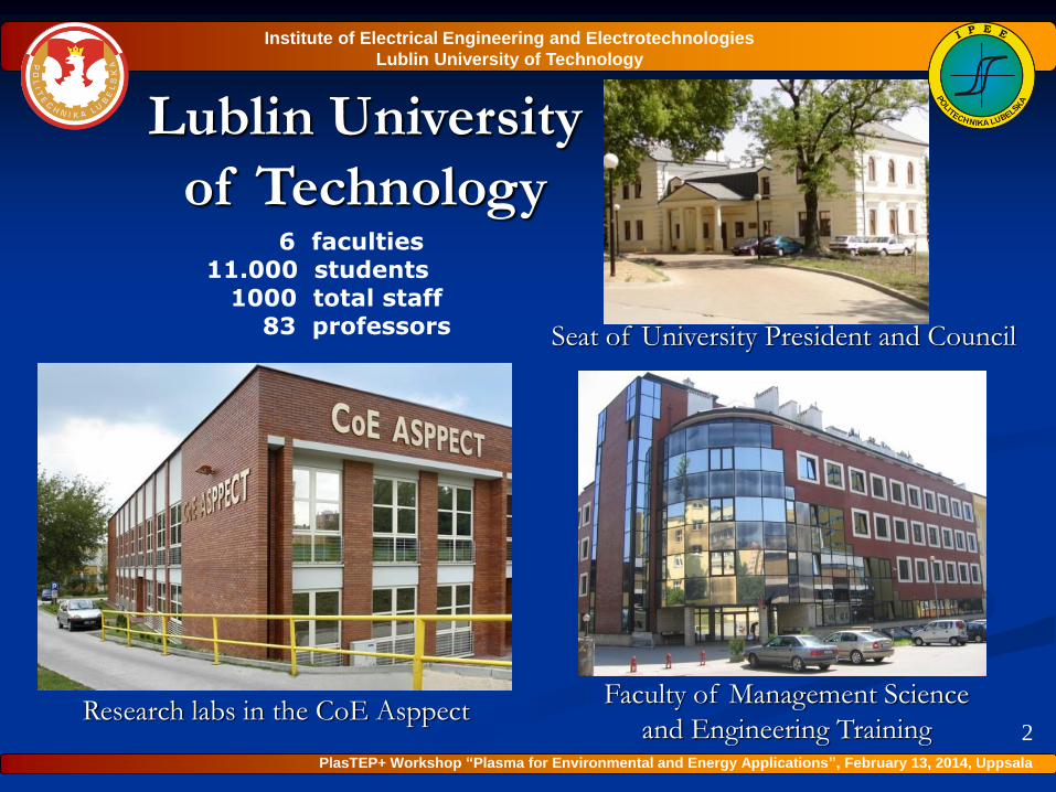
Lublin University
of Technology
Research labs in the CoE AsppectFaculty of Management Science
and Engineering Training
6 faculties11.000 students
1000 total staff83 professors Seat of University President and Council
Institute of Electrical Engineering and Electrotechnologies
Lublin University of Technology
2
PlasTEP+ Workshop “Plasma for Environmental and Energy Applications”, February 13, 2014, Uppsala
Plasma Technologies in Environment Protection
industrial ozone generators and water conditioning,
plasma reactors to remove gaseous pollutants,
electrical supply systems for ozonizers and plasma reactors,
bio-medical application: sterilization, disinfection, skin treatment,
mathematical modeling of the arc discharge reactors.
The major research and development areas
in the COE ASPPECT and Institute of EE&Et of LUT
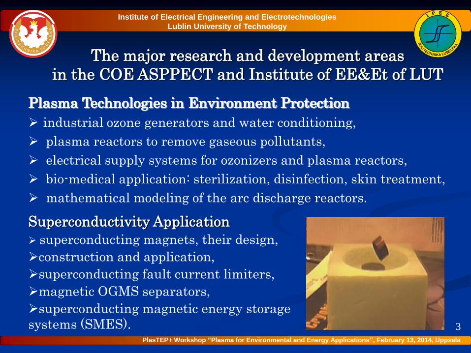
Superconductivity Application
superconducting magnets, their design,
construction and application,
superconducting fault current limiters,
magnetic OGMS separators,
superconducting magnetic energy storage
systems (SMES).
Institute of Electrical Engineering and Electrotechnologies
Lublin University of Technology
3
PlasTEP+ Workshop “Plasma for Environmental and Energy Applications”, February 13, 2014, Uppsala
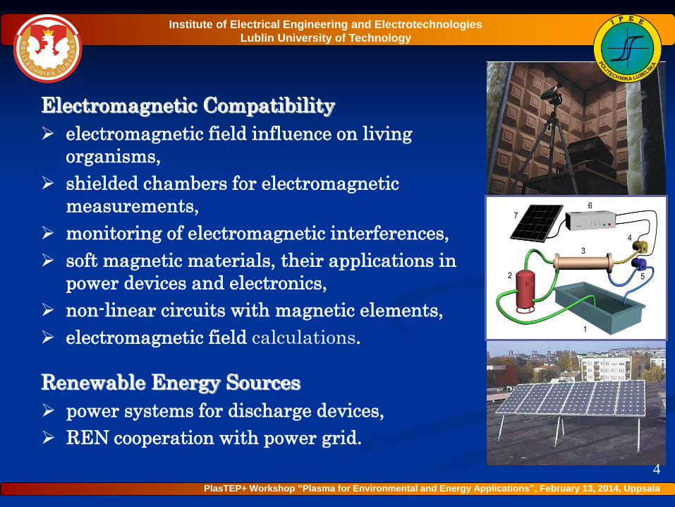
Electromagnetic Compatibility
electromagnetic field influence on living
organisms,
shielded chambers for electromagnetic
measurements,
monitoring of electromagnetic interferences,
soft magnetic materials, their applications in
power devices and electronics,
non-linear circuits with magnetic elements,
electromagnetic field calculations.
4
Institute of Electrical Engineering and Electrotechnologies
Lublin University of Technology
Renewable Energy Sources
power systems for discharge devices,
REN cooperation with power grid.
PlasTEP+ Workshop “Plasma for Environmental and Energy Applications”, February 13, 2014, Uppsala
OUTLINE
Gliding arc plasma reactor
Power supply systems for gliding arc plasma reactors
Experimental results
Conclusion
5
Institute of Electrical Engineering and Electrotechnologies
Lublin University of Technology
PlasTEP+ Workshop “Plasma for Environmental and Energy Applications”, February 13, 2014, Uppsala
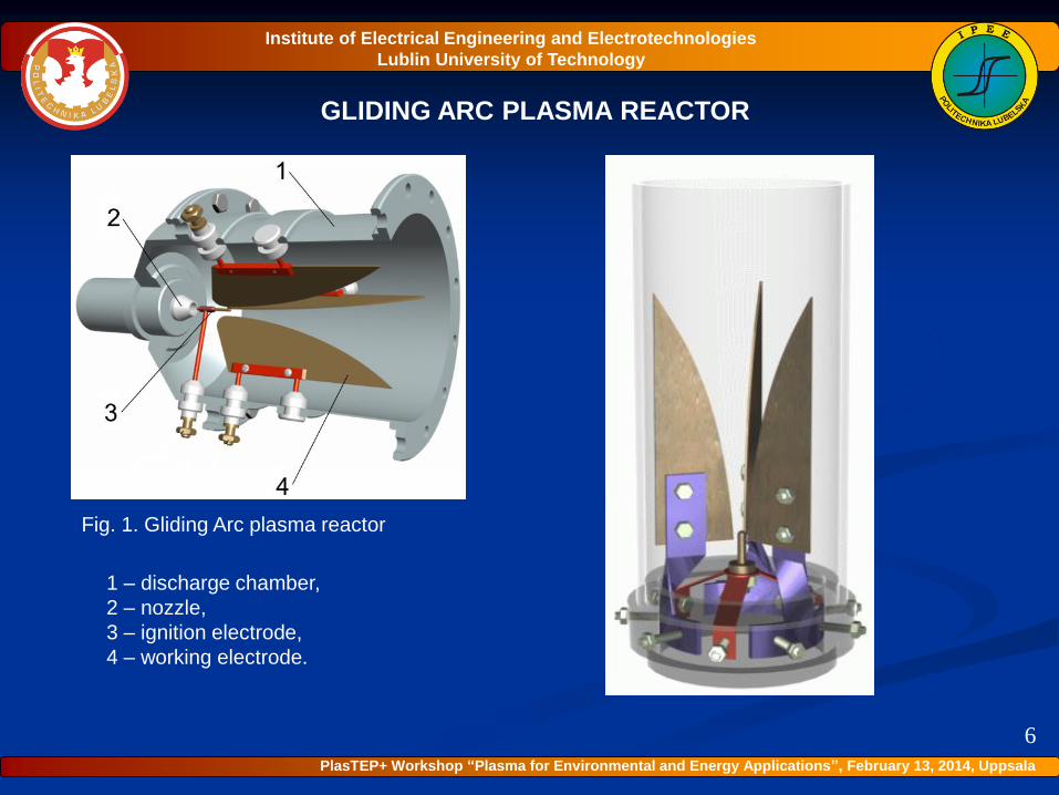
GLIDING ARC PLASMA REACTOR
1 – discharge chamber,
2 – nozzle,
3 – ignition electrode,
4 – working electrode.
Fig. 1. Gliding Arc plasma reactor
6
Institute of Electrical Engineering and Electrotechnologies
Lublin University of Technology
PlasTEP+ Workshop “Plasma for Environmental and Energy Applications”, February 13, 2014, Uppsala
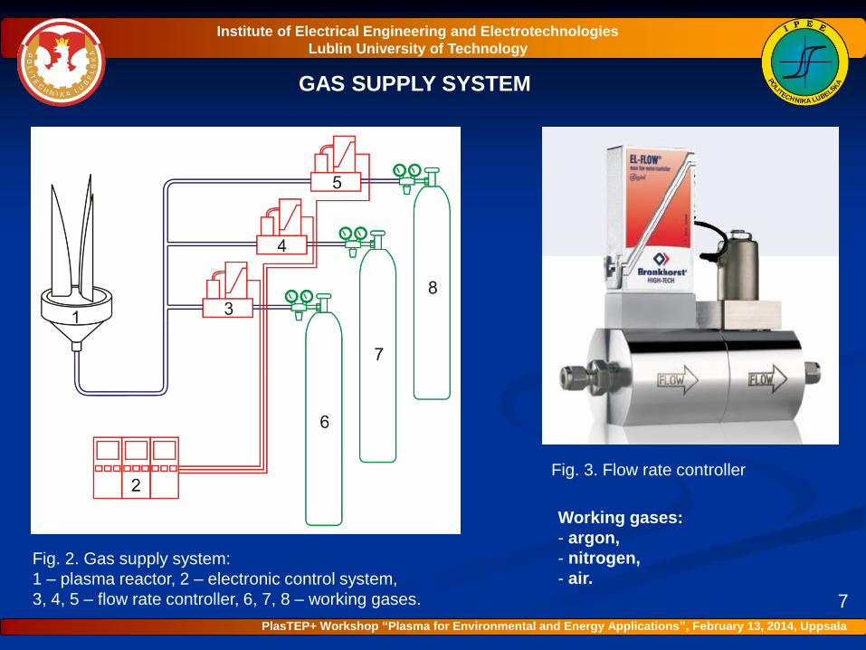
GAS SUPPLY SYSTEM
Fig. 2. Gas supply system:
1 – plasma reactor, 2 – electronic control system,
3, 4, 5 – flow rate controller, 6, 7, 8 – working gases.
Fig. 3. Flow rate controller
Working gases:
- argon,
- nitrogen,
- air.
7
Institute of Electrical Engineering and Electrotechnologies
Lublin University of Technology
PlasTEP+ Workshop “Plasma for Environmental and Energy Applications”, February 13, 2014, Uppsala
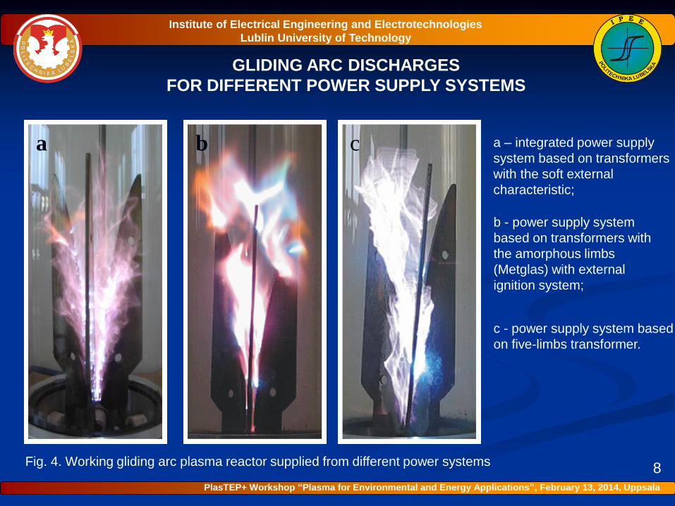
GLIDING ARC DISCHARGES
FOR DIFFERENT POWER SUPPLY SYSTEMS
a – integrated power supply
system based on transformers
with the soft external
characteristic;
b - power supply system
based on transformers with
the amorphous limbs
(Metglas) with external
ignition system;
c - power supply system based
on five-limbs transformer.
a b c
8
Institute of Electrical Engineering and Electrotechnologies
Lublin University of Technology
PlasTEP+ Workshop “Plasma for Environmental and Energy Applications”, February 13, 2014, Uppsala
Fig. 4. Working gliding arc plasma reactor supplied from different power systems
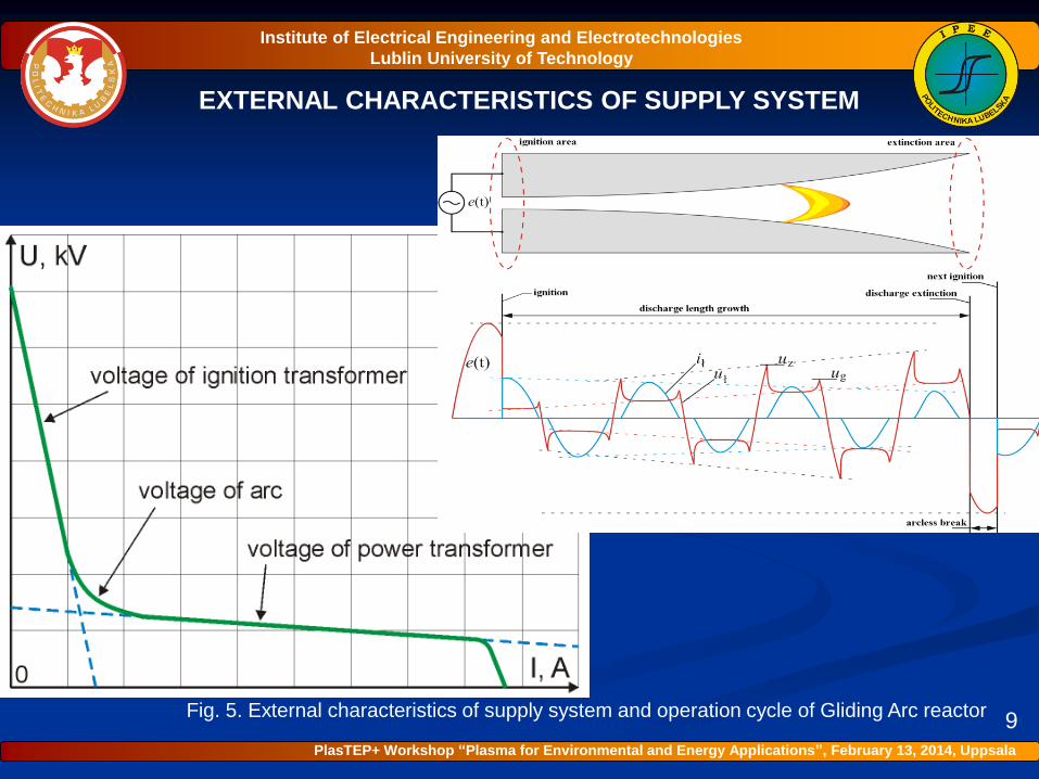
EXTERNAL CHARACTERISTICS OF SUPPLY SYSTEM
9Fig. 5. External characteristics of supply system and operation cycle of Gliding Arc reactor
Institute of Electrical Engineering and Electrotechnologies
Lublin University of Technology
PlasTEP+ Workshop “Plasma for Environmental and Energy Applications”, February 13, 2014, Uppsala
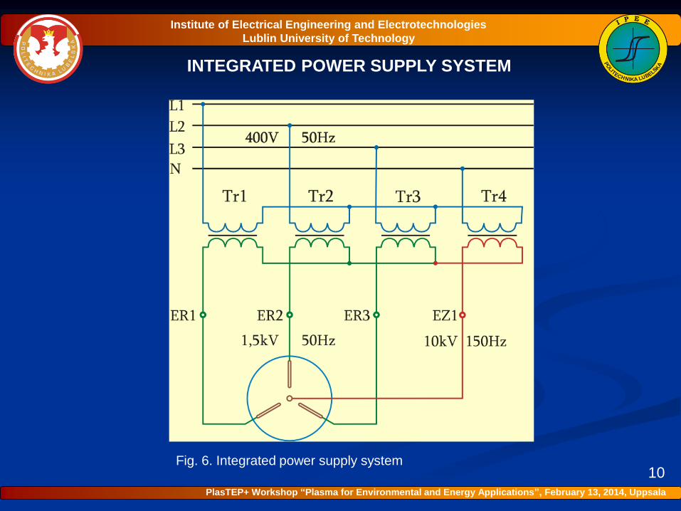
INTEGRATED POWER SUPPLY SYSTEM
10Fig. 6. Integrated power supply system
Institute of Electrical Engineering and Electrotechnologies
Lublin University of Technology
PlasTEP+ Workshop “Plasma for Environmental and Energy Applications”, February 13, 2014, Uppsala
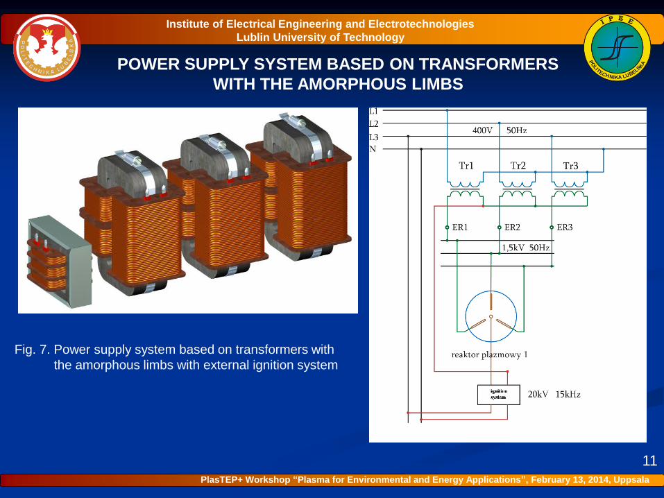
POWER SUPPLY SYSTEM BASED ON TRANSFORMERS
WITH THE AMORPHOUS LIMBS
11
Fig. 7. Power supply system based on transformers with
the amorphous limbs with external ignition system
Institute of Electrical Engineering and Electrotechnologies
Lublin University of Technology
PlasTEP+ Workshop “Plasma for Environmental and Energy Applications”, February 13, 2014, Uppsala
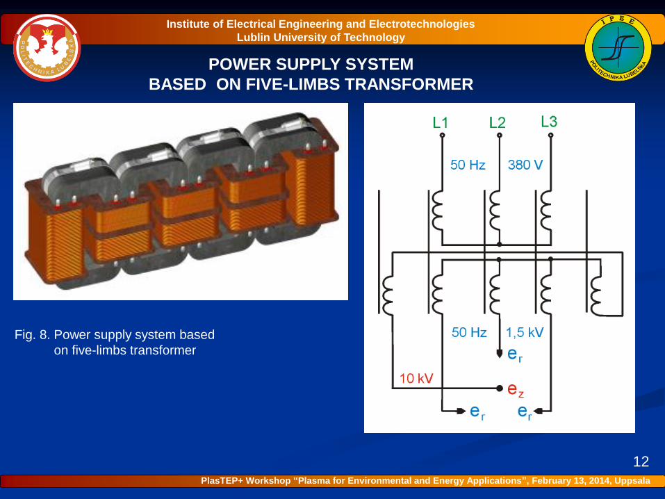
POWER SUPPLY SYSTEM
BASED ON FIVE-LIMBS TRANSFORMER
12
Fig. 8. Power supply system based
on five-limbs transformer
Institute of Electrical Engineering and Electrotechnologies
Lublin University of Technology
PlasTEP+ Workshop “Plasma for Environmental and Energy Applications”, February 13, 2014, Uppsala
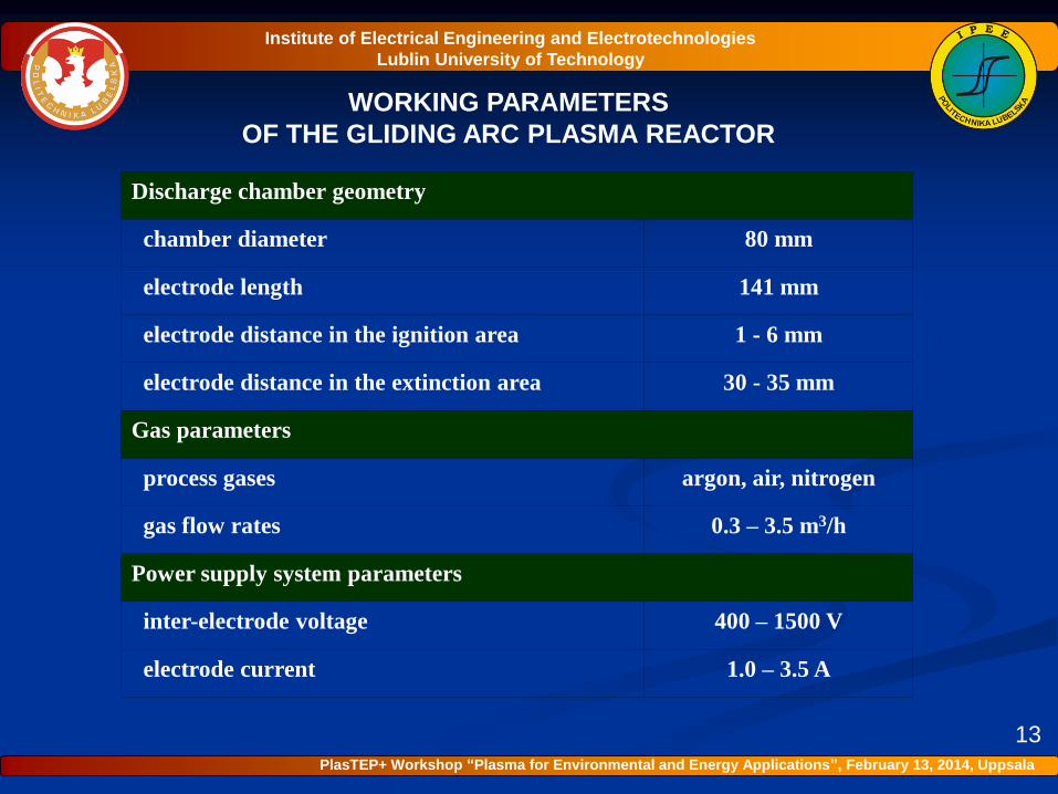
WORKING PARAMETERS
OF THE GLIDING ARC PLASMA REACTOR
13
Discharge chamber geometry
chamber diameter 80 mm
electrode length 141 mm
electrode distance in the ignition area 1 - 6 mm
electrode distance in the extinction area 30 - 35 mm
Gas parameters
process gases argon, air, nitrogen
gas flow rates 0.3 – 3.5 m3/h
Power supply system parameters
inter-electrode voltage 400 – 1500 V
electrode current 1.0 – 3.5 A
Institute of Electrical Engineering and Electrotechnologies
Lublin University of Technology
PlasTEP+ Workshop “Plasma for Environmental and Energy Applications”, February 13, 2014, Uppsala
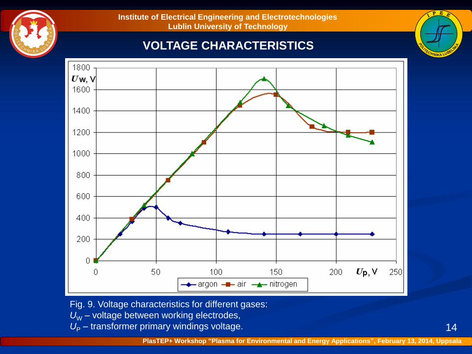
VOLTAGE CHARACTERISTICS
Fig. 9. Voltage characteristics for different gases:
UW – voltage between working electrodes,
UP – transformer primary windings voltage. 14
Institute of Electrical Engineering and Electrotechnologies
Lublin University of Technology
PlasTEP+ Workshop “Plasma for Environmental and Energy Applications”, February 13, 2014, Uppsala
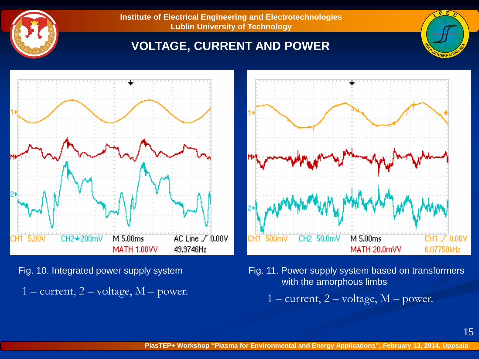
VOLTAGE, CURRENT AND POWER
15
Fig. 10. Integrated power supply system Fig. 11. Power supply system based on transformers
with the amorphous limbs1 – current, 2 – voltage, M – power.
1 – current, 2 – voltage, M – power.
Institute of Electrical Engineering and Electrotechnologies
Lublin University of Technology
PlasTEP+ Workshop “Plasma for Environmental and Energy Applications”, February 13, 2014, Uppsala
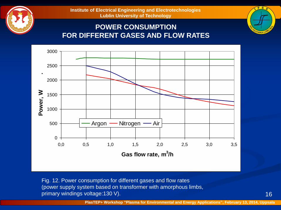
POWER CONSUMPTION
FOR DIFFERENT GASES AND FLOW RATES
Fig. 12. Power consumption for different gases and flow rates
(power supply system based on transformer with amorphous limbs,
primary windings voltage:130 V). 16
0
500
1000
1500
2000
2500
3000
0,0 0,5 1,0 1,5 2,0 2,5 3,0 3,5
Gas flow rate, m3/h
Po
wer,
W
.
Argon Nitrogen Air
Institute of Electrical Engineering and Electrotechnologies
Lublin University of Technology
PlasTEP+ Workshop “Plasma for Environmental and Energy Applications”, February 13, 2014, Uppsala
POWER CONSUMPTION
TRANSFORMERS WITH AMORPHOUS LIMBS
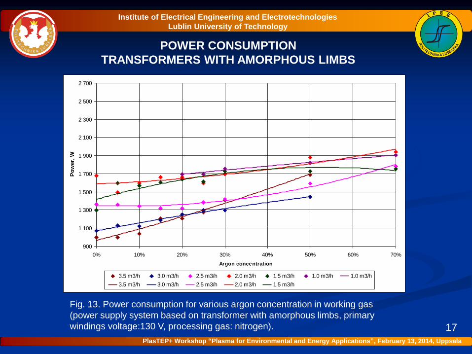
Fig. 13. Power consumption for various argon concentration in working gas
(power supply system based on transformer with amorphous limbs, primary
windings voltage:130 V, processing gas: nitrogen). 17
900
1 100
1 300
1 500
1 700
1 900
2 100
2 300
2 500
2 700
0% 10% 20% 30% 40% 50% 60% 70%
Argon concentration
Po
wer,
W
3.5 m3/h 3.0 m3/h 2.5 m3/h 2.0 m3/h 1.5 m3/h 1.0 m3/h 1.0 m3/h
3.5 m3/h 3.0 m3/h 2.5 m3/h 2.0 m3/h 1.5 m3/h
Institute of Electrical Engineering and Electrotechnologies
Lublin University of Technology
PlasTEP+ Workshop “Plasma for Environmental and Energy Applications”, February 13, 2014, Uppsala
POWER CONSUMPTION
INTEGRATED POWER SUPPLY SYSTEM
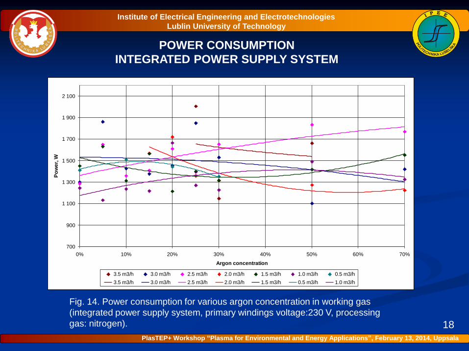
Fig. 14. Power consumption for various argon concentration in working gas
(integrated power supply system, primary windings voltage:230 V, processing
gas: nitrogen). 18
700
900
1 100
1 300
1 500
1 700
1 900
2 100
0% 10% 20% 30% 40% 50% 60% 70%
Argon concentration
Po
we
r, W
3.5 m3/h 3.0 m3/h 2.5 m3/h 2.0 m3/h 1.5 m3/h 1.0 m3/h 0.5 m3/h
3.5 m3/h 3.0 m3/h 2.5 m3/h 2.0 m3/h 1.5 m3/h 0.5 m3/h 1.0 m3/h
Institute of Electrical Engineering and Electrotechnologies
Lublin University of Technology
PlasTEP+ Workshop “Plasma for Environmental and Energy Applications”, February 13, 2014, Uppsala
POWER CONSUMPTION
FIVE-LIMBS TRANSFORMER
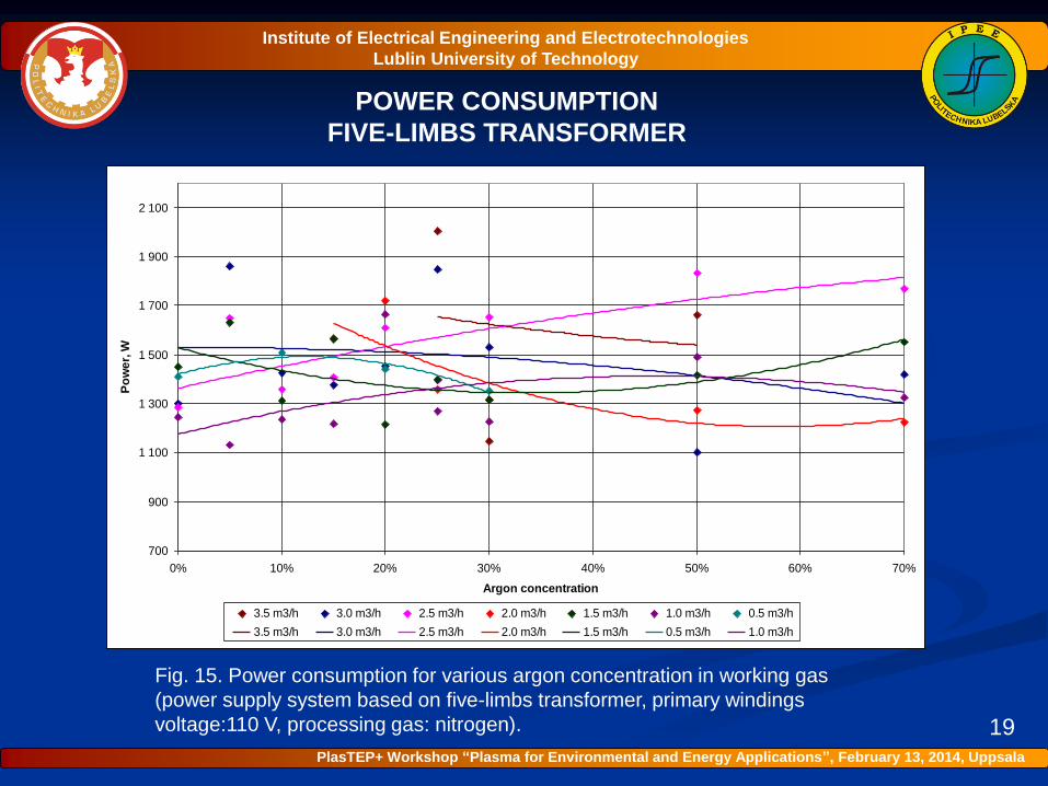
Fig. 15. Power consumption for various argon concentration in working gas
(power supply system based on five-limbs transformer, primary windings
voltage:110 V, processing gas: nitrogen). 19
700
900
1 100
1 300
1 500
1 700
1 900
2 100
0% 10% 20% 30% 40% 50% 60% 70%
Argon concentration
Po
we
r, W
3.5 m3/h 3.0 m3/h 2.5 m3/h 2.0 m3/h 1.5 m3/h 1.0 m3/h 0.5 m3/h
3.5 m3/h 3.0 m3/h 2.5 m3/h 2.0 m3/h 1.5 m3/h 0.5 m3/h 1.0 m3/h
Institute of Electrical Engineering and Electrotechnologies
Lublin University of Technology
PlasTEP+ Workshop “Plasma for Environmental and Energy Applications”, February 13, 2014, Uppsala
DISCHARGE CURRENT
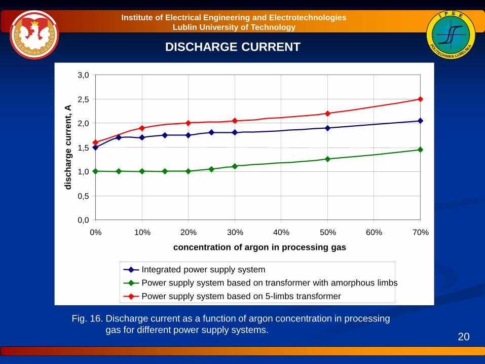
Fig. 16. Discharge current as a function of argon concentration in processing
gas for different power supply systems.20
Institute of Electrical Engineering and Electrotechnologies
Lublin University of Technology
0,0
0,5
1,0
1,5
2,0
2,5
3,0
0% 10% 20% 30% 40% 50% 60% 70%
concentration of argon in processing gas
dis
ch
arg
e c
urr
en
t, A
Integrated power supply system
Power supply system based on transformer with amorphous limbs
Power supply system based on 5-limbs transformer
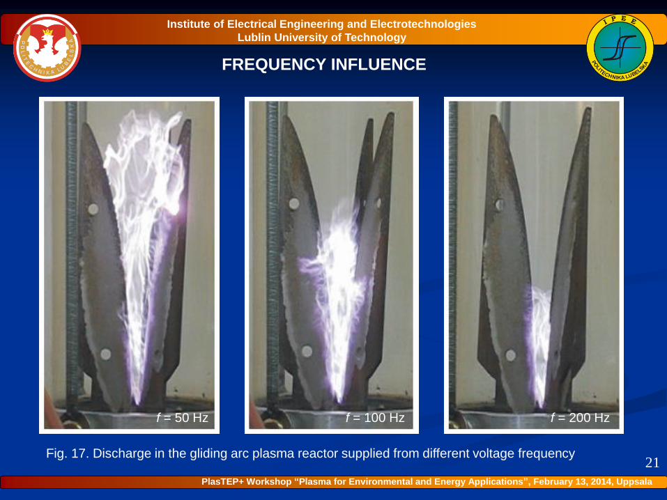
FREQUENCY INFLUENCE
f = 50 Hz
21
f = 100 Hz f = 200 Hz
Institute of Electrical Engineering and Electrotechnologies
Lublin University of Technology
PlasTEP+ Workshop “Plasma for Environmental and Energy Applications”, February 13, 2014, Uppsala
Fig. 17. Discharge in the gliding arc plasma reactor supplied from different voltage frequency
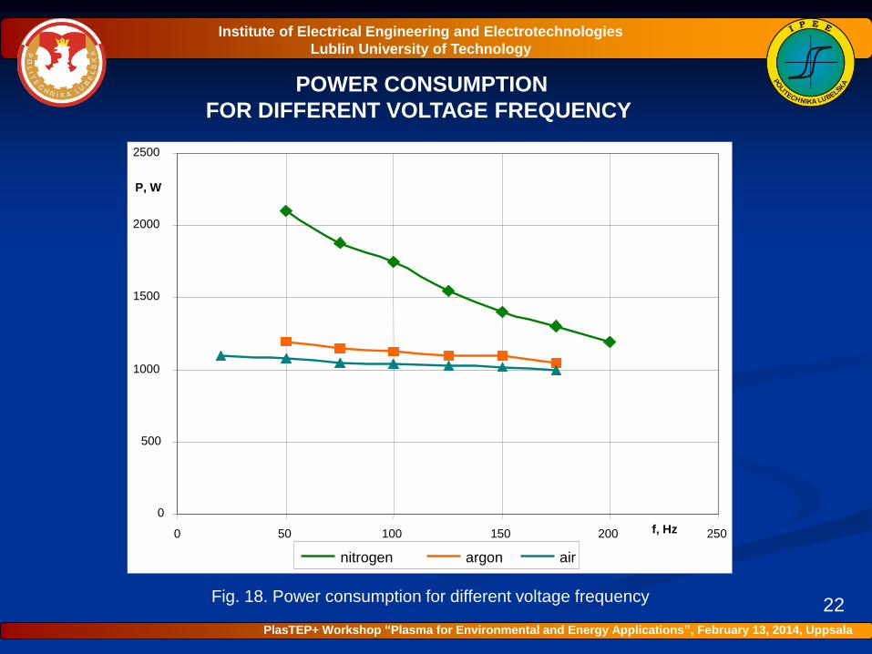
POWER CONSUMPTION
FOR DIFFERENT VOLTAGE FREQUENCY
Fig. 18. Power consumption for different voltage frequency22
Institute of Electrical Engineering and Electrotechnologies
Lublin University of Technology
0
500
1000
1500
2000
2500
0 50 100 150 200 250f, Hz
P, W
nitrogen argon air
PlasTEP+ Workshop “Plasma for Environmental and Energy Applications”, February 13, 2014, Uppsala
CONCLUSION
23
Power consumption of the gliding arc discharge plasma rector and its stable
operation depends on many factors, among which the most important are:
• power supply system configuration,
• processing gas flow rate,
• processing gas chemical composition.
Trace gases admixtures can essentially influence the plasma chemistry process.
Argon admixture to the processing gas stabilizes the discharge and makes
possible to transfer larger power from the power supply system to the
discharge.
Correctly selected power supply system decides about plasma chemistry and
technological application of this kind of non-thermal non-equilibrium plasma.
Institute of Electrical Engineering and Electrotechnologies
Lublin University of Technology
PlasTEP+ Workshop “Plasma for Environmental and Energy Applications”, February 13, 2014, Uppsala