gmbh info @ widos.de internet: working ... · gmbh info @ widos.de internet: www ... especially...
TRANSCRIPT

WIDOS Einsteinstr. 5 Phone +49 71 52 99 39 0 Wilhelm Dommer Söhne D-71254 Ditzingen Fax +49 71 52 99 39 40 GmbH info @ widos.de Internet: www.widos.de
Headquarters: D-71254 Ditzingen Country court Stuttgart HRB 200973 Managing directors: Jürgen Dommer, Dr. Kai Dombrowski
Working Instructions Translation
Heating element butt welding machine
WIDOS 4002 S WI CNC®
Keep for further use!

Identification of product
14.11.2016 Working instructions WIDOS 4002 S WI CNC Page 2 of 103
Model: Workshop machine
Type: WIDOS 4002 S WI-CNC®
Serial number, year of construction: see type plate
Customer entries
Inventory-no.:
Location: Order of spare parts and after sales service: Manufacturer’s address WIDOS Wilhelm Dommer Söhne GmbH Einsteinstr. 5
D -71254 Ditzingen Phone: +49 (0) 71 52 99 39 0 Fax: +49 (0) 71 52 99 39 40 E-Mail: [email protected]

Introduction
14.11.2016 Working instructions WIDOS 4002 S WI CNC Page 3 of 103
Purpose of the document These working instructions give you information about all important questions which refer to the construction and the safe working of your machine. Just as we are, you are obliged to engage in these working instructions, as well. Not only to run your machine economically but also to avoid damages and injuries. Should questions arise, contact our advisers in the factory or in our subsidiary companies. We will help you with pleasure.
According to our interest in making our products and working instructions continuously better, we kindly ask you to inform us about problems and defects which occur in exercise. Thank you.
Structure of the working instructions The working instructions are arranged in chapters, which belong to the different using phases of the machine. Therefore the searched information can be found easily.
11/14/2016 WIDOS
Wilhelm Dommer Söhne GmbH Einsteinstraße 5
D-71254 Ditzingen
All rights reserved.
Reprinting only allowed with permission of the corporation. Any changes are subject to technical innovations.

Contents
14.11.2016 Working instructions WIDOS 4002 S WI CNC Page 4 of 103
1. DESCRIPTION OF PRODUCT .......................................................................... 7 1.1. Usage and purpose-oriented use ............................................................................................... 7
1.2. Safety measures ........................................................................................................................ 7
1.3. Conformity ................................................................................................................................. 7
1.4. Marking of the product .............................................................................................................. 8
1.4.1. Technical data .................................................................................................................... 8
1.4.1.1. WIDOS 4002 S WI-CNC General data .............................................................................. 8
1.4.1.2. Basic machine .................................................................................................................. 8
1.4.1.3. Heating element ............................................................................................................... 9 1.4.1.4. Planer .............................................................................................................................. 9 1.4.1.5. 3-zone heating element (optional) ....................................................................................... 9
1.5. Tools and accessories ............................................................................................................... 9
2. SAFETY RULES .............................................................................................. 10 2.1. Explanation of the different symbols ........................................................................................ 10
2.2. Obligations of the owner .......................................................................................................... 11
2.3. Obligations of the worker ......................................................................................................... 11
2.4. Measures of organization ........................................................................................................ 11
2.5. Information about safety precautions ...................................................................................... 11
2.6. Instructions for the staff .......................................................................................................... 11
2.7. Maintenance and inspection, repair ........................................................................................ 12
2.8. Dangers while handling the machine ....................................................................................... 12
2.9. Dangers due to electrical energy ............................................................................................. 12
2.10. Dangers due to the pneumatic ................................................................................................. 12
2.11. Special dangers ...................................................................................................................... 13
2.11.1. Danger of combustion at the heating element and at the welding area ................................... 13
2.11.2. Danger of crushing by clamping tools and guide rods ........................................................... 13
2.11.3. Danger of catching clothes by the planer ............................................................................. 13
2.11.4. Danger of stumbling over pneumatic and electric cables ...................................................... 13
2.11.5. Risk of injury by noise ........................................................................................................ 13
2.12. Warranty and liability .............................................................................................................. 14
3. DESCRIPTION OF PROCESS ........................................................................ 15
4. OPERATING AND INDICATING ELEMENTS ............................................... 16 4.1. Elements on the front side ....................................................................................................... 16
4.2. Elements on the right side ....................................................................................................... 17
4.2.1. Main switch ...................................................................................................................... 17
4.2.2. Service unit ...................................................................................................................... 17
4.3. Pneumatic components on the machine ................................................................................... 18

Contents
14.11.2016 Working instructions WIDOS 4002 S WI CNC Page 5 of 103
4.4. Socket at the machine (at the front) ......................................................................................... 19
4.5. Elements at the heating element .............................................................................................. 19
5. STARTING AND OPERATING ...................................................................... 20 5.1. Starting ................................................................................................................................... 20
5.2. Separating claws ..................................................................................................................... 20
5.3. Description of the display ........................................................................................................ 21
5.3.1. Emergency-stop ................................................................................................................ 21
5.4. Buttons on the touch screen .............................................................................................. 22
5.4.1. Small symbol buttons ......................................................................................................... 22
5.4.2. Large symbol buttons ......................................................................................................... 23
5.5. Accessories for reading data in and out (option) ...................................................................... 24
5.5.1. Legitimacy cards ............................................................................................................... 24
5.5.2. Bar code scanner .............................................................................................................. 24
5.5.3. SD card and drive .............................................................................................................. 24
5.5.4. Read out WICON with USB flash drive ................................................................................. 25
5.6. Switching the WI – CNC® 1.1 / 1.3 on ................................................................................. 26
5.6.1. Select machine type with digital way-measuring device ....................................................... 27
5.6.2. Define dimension ............................................................................................................... 29
5.6.3. Specialties for welding standard >LAB< .............................................................................. 31
5.6.4. How to enter further settings like traceability, ½ cooling time or RAM > USB ........................... 35
5.6.4.1. How to set date, time, buzzer and language ....................................................................... 36
5.7. Welding with the WI–CNC® 1.1 - 1.3 ................................................................................... 38
5.7.1. Copy internal data onto SD card and delete internal data (RAM) ............................................ 50
5.8. Setting the welding angle ........................................................................................................ 52
5.8.1. Welding of T-piece 90° ....................................................................................................... 52
5.8.2. Drillings at the table ........................................................................................................... 53
6. EQUIPMENT CARE / MAINTENANCE / REPAIR ......................................... 54 6.1. Maintenance and inspection, repair ................................................................................... 54
6.2. How to clean the operator panel (touch screen) .............................................................. 54
6.3. Fuses in the switch cabinet ..................................................................................................... 55
6.4. Safety switch and end switch at tghe machine ........................................................................ 55
6.5. Clamping elements .................................................................................................................. 56
6.6. Planer ..................................................................................................................................... 56
6.7. Storage .................................................................................................................................. 56
6.8. Disposal ................................................................................................................................ 56
7. TRANSPORT .................................................................................................. 57 7.1. WI-CNC® 1.1 / 1.3 ..................................................................................................................... 57
7.2. 4002 S CNC .............................................................................................................................. 57

Contents
14.11.2016 Working instructions WIDOS 4002 S WI CNC Page 6 of 103
8. ELECTRIC AND PNEUMATIC DIAGRAMS .................................................. 58 8.1. Pneumatic diagram .............................................................................................................. 58
8.2. Electric diagrams for 4002 S WI-CNC® ............................................................................... 59
9. SPARE PARTS LIST ...................................................................................... 85 9.1. Basic machine ......................................................................................................................... 85
9.2. Clamping tool .......................................................................................................................... 89
9.3. Planer ..................................................................................................................................... 90
9.4. Heating element ...................................................................................................................... 92
9.5. 3-zone heating element (variant) .............................................................................................. 93
9.6. Heating element holder ........................................................................................................... 94
9.7. Beam for one-sided planing ..................................................................................................... 95
10. DECLARATION OF CONFORMITY .............................................................. 103

WIDOS Einsteinstr. 5 Phone +49 71 52 99 39 0 Wilhelm Dommer Söhne D-71254 Ditzingen Fax +49 71 52 99 39 40 GmbH info @ widos.de Internet: www.widos.de
14.11.2016 Working instructions WIDOS 4002 S WI CNC Page 7 of 103
1. Description of product This chapter gives important basic information about the product and its prescribed use. All technical details of the machine are put together as a general arrangement.
1.1. Usage and purpose-oriented use
The WIDOS 4002 S WI-CNC is a workshop machine and especially designed for the heating element butt welding of plastic pipes and fittings from Ø = 90 up to 315 mm (Standard-: 90 / 110 / 125 / 140 / 160 / 180 / 200 / 225 / 250 / 280 / 315 mm).
The machine is screwed tightly on a steel pipe frame in the correct working height and has a movable machine slide (left-hand) and 2 (optional 4) clamping tools. For the compensation of diameter tolerances, the right table half is movable crosswise to the working direction.
For the fabrication of segmented bends, both clamping tools are swiveling up to 15° each. All use going beyond is not prescribed.
The manufacturer is not responsible for damages caused by misuse.
The risk is held only by the user.
Also part of the appropriate usage are
following all indications of the working instructions and
performing the inspection and maintenance works.
1.2. Safety measures
At incorrect usage of the machine, incorrect operation or incorrect maintenance, the machine itself or products being around can be damaged or destroyed.
Persons in the dangerous zone may be injured.
For that reason, these working instructions have to be read thoroughly and the according safety rules have absolutely to be followed.
1.3. Conformity
The machine corresponds in its construction to the valid recommendations of the European Community as well as to the according European standard specifications.
The development, manufacturing and mounting of the machine were made very carefully.

Description of product Chapter 1
14.11.2016 Working instructions WIDOS 4002 S WI CNC Page 8 of 103
1.4. Marking of the product
The product is marked by a type-plate at the basic machine.
It contains the machine type, the serial number and the year of construction.
1.4.1. Technical data
All important technical data of the singular components are mentioned.
This allows a quickly information about the capacity and the structure.
1.4.1.1. WIDOS 4002 S WI-CNC General data
Material: PP; PE, PVC, C-PVC, PVDF, Pipe dimension: Outside- = 90 - 315 Voltage: 230 V / 3 Ph Frequency: 50 Hz /60 Hz Power: 5,8 kVA Wires cross section: 1,5 mm² Max. working pressure: 8 bar Weight, without reducer inserts and packing):
325 kg
Dimensions: (width x depth x height)
1000 x 1500 x 1300 mm 1000 x 1600 x 1400 mm (with conversion kit)
Emissions - The sound pressure level during planing is below 80 dB (A) - In case of use of the prescribed plastics and if the work is
performed within the temperature range up to 260 °C / 500 °F, no toxic fumes will be generated.
Environmental conditions in the welding area
- Be aware of cleanliness (no dust at the welding spot) - If secured by appropriate measures that allowed conditions for
welding are indicated, it is possible – insofar as the welder is not handicapped in his skills - to work at any outside.
- protect from moisture influence - avoid strong sun radiation - protect from strong wind - attention when swiveling out the heating element
1.4.1.2. Basic machine
Frame material: Construction steel Servo motor: Power: 2,89 kW Voltage: 230 V ( 10 %) Amperage: 6,3 A Frequency: 50 Hz / 60 Hz Type of protection: IP 55 Engine revolution: 4000 (U/min) Driving torque: max. 8,2 Nm

Description of product Chapter 1
14.11.2016 Working instructions WIDOS 4002 S WI CNC Page 9 of 103
1.4.1.3. Heating element
Power: 3,5 kW Voltage: 230 V ( 10 %) / 3 Ph Amperage per phase: 15,2 A ( 10 %) Frequency: 50 Hz / 60 Hz Surface: anti-stick coated
1.4.1.4. Planer
Motor: Three-phase universal motor Power: 0,37 kW Voltage: 230 V ( 10 %) / 3 Ph Amperage: 1,02 A Frequency: 50 Hz / 60 Hz ( 10 %)
1.4.1.5. 3-zone heating element (optional)
Power: 3,8 kW Voltage: 230 V ( 10 %) / 3 Ph Amperage per phase: 16,6 A ( 10 %) Frequency: 50 Hz / 60 Hz Surface: anti-stick coated
1.5. Tools and accessories
The following tools and accessories are part of the first delivery:
1 Key for switch cabinet 1 Ring/fork wrench size SW 19 1 Tubular hexagon box wrench size 27
each 1 Allen key with T-grip size 4; 5; 6 each 1 Allen key bent size 3; 6; 7; 8
Order numbers and singular components on request at the WIDOS company.
The following optional accessories are available on request:
- Program WICON for reading out the data (possibility of displaying included in USB stick)

WIDOS Einsteinstr. 5 Phone +49 71 52 99 39 0 Wilhelm Dommer Söhne D-71254 Ditzingen Fax +49 71 52 99 39 40 GmbH info @ widos.de Internet: www.widos.de
14.11.2016 Working instructions WIDOS 4002 S WI CNC Page 10 of 103
2. Safety rules The basic condition for the safety conscious handling and the fault free operation of this machine is the knowledge of the basic safety advises and rules.
These working instructions contain the most important indications for running the machine according to the safety regulations.
The safety indications need to be followed by all persons working on the machine.
2.1. Explanation of the different symbols
The following denominations and symbols indicating dangers are used in the working instructions:
This symbol signifies a possible endangering for the life and the health of persons.
Not following these indications may conduct to severe consequences for health.
This symbol means a potential dangerous situation.
Not following these indications may conduct to slight injuries or damages on goods.
This symbol means a possible dangerous situation due to hot surfaces.
The non-respect of these indications may conduct to heavy burns, respectively to self-ignition or even fire.
This symbol means a possible dangerous situation by moving parts of the machine
The disrespect of these indications may cause heavy crushing of parts of the body resp. damages of parts of the machine.
This symbol means a possible risk of injury by noises exceeding 80 dB (A).
Ear protection is obligatory
This symbol gives the most important indications for the appropriate handling of the machine.
Not following these indications may conduct to disturbances and damages on the machine or items in the surrounding.
Under this symbol you will get tips and particularly important information.
This shall help you to use all functions of the machine in an optimal way and makes the work easier for you.
T h e a c c i d e n t p r e v e n t i o n m e a s u r e s a r e v a l i d ( U V V ) .

Safety rules Chapter 2
14.11.2016 Working instructions WIDOS 4002 S WI CNC Page 11 of 103
2.2. Obligations of the owner
The owner is obliged only to let persons work at the machine, who know about basic safety and accident prevention rules and are instructed in the handling of the machine,
as well as who
have read and understood the safety chapter of this manual and certify this by their signature.
The safety-conscious working of the staff has to be checked in regular intervals.
2.3. Obligations of the worker
All persons who are to work at the machine are obliged before working:
To follow the basic safety and accident protection rules;
To have read and understood the safety chapter and the warnings in this manual and to confirm by their signature that they have well understood them;
To inform themselves about the functions of the machine before using it.
2.4. Measures of organization
All equipment required for personal safety is to be provided by the owner.
All available safety equipment is to be inspected regularly.
2.5. Information about safety precautions
The working instructions have to be permanently kept at the place of use of the machine. They are to be at the operator's disposal at any time and without effort.
In addition to the manual, the common valid and the local accident protection rules and regulations for the environmental protection must be available and followed.
All safety and danger indications on the machine have to be in a clear readable condition.
Every time the machine changes hands or is being rent to third persons, the working instructions are to be sent along with and their importance is to be emphasized.
2.6. Instructions for the staff
It must be clearly defined who is responsible for transport, mounting and dismounting, starting the operation, setting and tooling, operation, maintenance and inspection, repair and dismounting.
Only skilled and trained persons are allowed to work at the machine.
A person who is being trained may only work at the machine under supervision of an experienced person.

Safety rules Chapter 2
14.11.2016 Working instructions WIDOS 4002 S WI CNC Page 12 of 103
2.7. Maintenance and inspection, repair
All maintenance and repair work are to be basically performed with the machine in off-position. During this, the machine has to be secured against unintended switching on.
Prescribed maintenance and inspection work have to be performed in time. The DVS recommends inspection work after 1 year. For machines with a specially high usage percentage, the inspection cycle should be shortened. The work must be performed at the WIDOS GmbH company or by an authorized partner.
2.8. Dangers while handling the machine
The machine WIDOS 4002 S WI-CNC is constructed according to the latest technical standard and the acknowledged technical safety rules. However, dangers for the operator or other persons standing nearby may occur. Also material damages are possible. The machine may only be used in safety-technical impeccable status.
Disturbances which may affect the safety of the machine must be cleared immediately.
2.9. Dangers due to electrical energy
Works on the electric parts may only be performed by skilled workers.
The electric equipment of the machine is to be checked regularly. Loose connections and damaged cables are to be replaced immediately.
If works on conductive parts are necessary, a second person is required who may switch the power off in case of emergency.
The machine is to be protected from rain and dropping water.
2.10. Dangers due to the pneumatic
Pressure lines have to be depressurized before any kind of repair.
There is a particular danger for the eyes due to compressed air emerging suddenly.
Replace defective pneumatic hoses immediately.
Make a visual inspection of the pneumatic lines before beginning to weld.
Safety rules Chapter 2
14.11.2016 Working instructions WIDOS 4002 S WI CNC Page 13 of 103
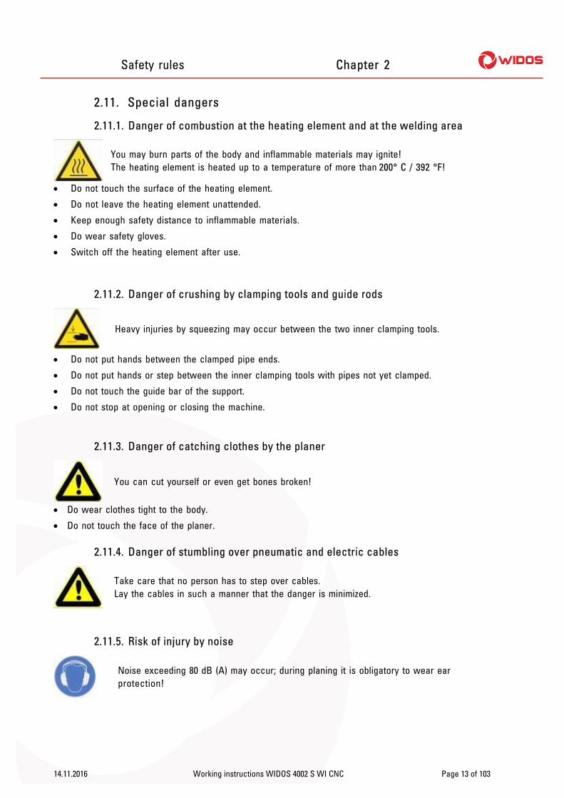
2.11. Special dangers
2.11.1. Danger of combustion at the heating element and at the welding area
You may burn parts of the body and inflammable materials may ignite! The heating element is heated up to a temperature of more than 200° C / 392 °F!
Do not touch the surface of the heating element.
Do not leave the heating element unattended.
Keep enough safety distance to inflammable materials.
Do wear safety gloves.
Switch off the heating element after use.
2.11.2. Danger of crushing by clamping tools and guide rods
Heavy injuries by squeezing may occur between the two inner clamping tools.
Do not put hands between the clamped pipe ends.
Do not put hands or step between the inner clamping tools with pipes not yet clamped.
Do not touch the guide bar of the support.
Do not stop at opening or closing the machine.
2.11.3. Danger of catching clothes by the planer
You can cut yourself or even get bones broken!
Do wear clothes tight to the body.
Do not touch the face of the planer.
2.11.4. Danger of stumbling over pneumatic and electric cables
Take care that no person has to step over cables. Lay the cables in such a manner that the danger is minimized.
2.11.5. Risk of injury by noise
Noise exceeding 80 dB (A) may occur; during planing it is obligatory to wear ear protection!

Safety rules Chapter 2
14.11.2016 Working instructions WIDOS 4002 S WI CNC Page 14 of 103
2.12. Warranty and liability
Basically, our "General Terms of sale and delivery“ are valid. They are at the owner’s disposal latest at conclusion of the contract. Guarantee an liability demands referring to personal injuries or damages on objects are excluded if they are caused by one or several of the following reasons: Not using the machine according to the prescriptions.
Unsuitable transport, mounting, starting, operating and maintenance of the machine.
Operating the machine without or with not correctly fixed safety devices.
Not following the indications of the working instructions.
Unauthorized structural modifications on the machine.
Unsatisfactory inspection of machine parts which are subject to wearing.
Unsatisfactory performed repairs.
In case of catastrophes through action of an external body or actions of God.

WIDOS Einsteinstr. 5 Phone +49 71 52 99 39 0 Wilhelm Dommer Söhne D-71254 Ditzingen Fax +49 71 52 99 39 40 GmbH info @ widos.de Internet: www.widos.de
14.11.2016 Working instructions WIDOS 4002 S WI CNC Page 15 of 103
3. Description of process B a s i c a l l y , t h e i n t e r n a t i o n a l a n d n a t i o n a l p r o c e s s g u i d e l i n e s a r e t o b e f o l l o w e d ! At first, the clamping tools are mounted on the slide.
For welding angles and bends, the clamping tools can be turned on both sides.
The plastic pipes are clamped by means of the clamping tools.
Then the front sides of the pipes are planed parallel and the misalignment of the pipes is checked.
Now the heating element is swiveled in and the pipes are pressed against the heating element under defined adjusting pressure (this process is called "bead up time").
After the prescribed bead height being reached, pressure is reduced, the heat up time begins.
The function of this time is to heat the pipe ends up to welding temperature.
After expiration of the heat up time, the slide is opened, the heating element is removed quickly and the pipes are closed again hydraulically.
The time gap from the removal of the heating element to joining the pipes is called change over time.
The pipes are joined under prescribed welding pressure and then cool down under pressure (cooling time).
The welded joint can be unclamped, the welding process is finished.
welded pipe with internal and external bead
Heating element heats the pipes up to welding temperature.

WIDOS Einsteinstr. 5 Phone +49 71 52 99 39 0 Wilhelm Dommer Söhne D-71254 Ditzingen Fax +49 71 52 99 39 40 GmbH info @ widos.de Internet: www.widos.de
14.11.2016 Working instructions WIDOS 4002 S WI CNC Page 16 of 103
4. Operating and indicating elements
4.1. Elements on the front side
No. Denomination 1 Heating element 2 Planer 3 Protective enclosure 4 Support angle and pipe bracket (option) 5 Switch cabinet with fuses etc. 6 Clamping tools 7 WI CNC with emergency-stop and USB connection 8 Heating element handle, here placed at the safety switch 9 Swinging WI-CNC with emergency-stop and USB connection (NEW replacing no. 7)
1
2
3
4
6
7
8 5

Operating and indicating elements Chapter 4
14.11.16 Working instructions WIDOS 4002 S WI CNC Page 17 of 103
4.2. Elements on the right side
No. Denomination 10 Main switch 11 Electric connecting cable 12 Service unit with pressure gauge (pneumatic) 13 Plug for compressed air hose, connection with local compressed air supply (not
included in delivery) 14 Manual outlet for condensed water
4.2.1. Main switch
You activate and shut the machine off with the main switch.
Shut the machine off during all work within the machine and secure the machine against unintentional activation.
4.2.2. Service unit
The service unit (LFR-1/8-D-7-MINI) adjusts the incoming compressed air to the set working pressure and compensates fluctuations in pressure. It frees the compressed air of dirt and condensation water. The use with any other fluid (liquid or gas) is a misapplication.
Adjusting the regulator: Slowly pressurize the complete system.
Pull the pressure setting button upwards (away from the housing).
Turn the pressure setting button until the desired pressure is shown on the manometer. The input pressure must be at least 1 bar higher than the output pressure.
Press the pressure setting button downwards (towards the housing) to secure it against unintentional turning.
14
10
13
12
11

Operating and indicating elements Chapter 4
14.11.16 Working instructions WIDOS 4002 S WI CNC Page 18 of 103
4.3. Pneumatic components on the machine
Nr. Benennung 15 QM21 Pneumatic valve for: heating element move out of machine
Nr. Benennung 16 BG21 Safety switch „release handle heating element“
15
Safety switch inactive
Safety switch active
(by heating element handle)
16

Operating and indicating elements Chapter 4
14.11.16 Working instructions WIDOS 4002 S WI CNC Page 19 of 103
4.4. Socket at the machine (at the front)
Nr. Benennung 17 XZ20 Heating element socket
4.5. Elements at the heating element
Standard heating element 3–zone heating element (optional)
There are 3 different states:
illuminating: only interrupted by short switch-off pulses: the heating element is being heated up, the desired temperature is not yet reached. The desired and the actual temperature are displayed alternating on the display of the control
blinking: the temperature of the heating element is maintained by a pulse-position ratio.
off: the desired temperature has been exceeded, the heating element is cooled automatically onto desired temperature, or the heating element is switched off.
Control lamp green
17

WIDOS Einsteinstr. 5 Phone +49 71 52 99 39 0 Wilhelm Dommer Söhne D-71254 Ditzingen Fax +49 71 52 99 39 40 GmbH info @ widos.de Internet: www.widos.de
14.11.2016 Working instructions WIDOS 4002 S WI CNC Page 20 of 103
5. Starting and operating The indications of this chapter are supposed to instruct you in the operation of the machine and to lead you during the skilled starting of the machine.
This includes:
the safe operation of the machine
using all possibilities
economic operation of the machine
5.1. Starting
The machine may only be operated by skilled and authorized persons. A plastic welder exam according to DVS and DVGW can be taken for the qualification.
In dangerous situations for man, workpiece or machine immediately push the emergency-stop or shut the machine off at the main switch.
Connect the mains plug with the local mains supply 400V / 3 Ph / 6,1 kVA / 50 Hz, right-handed rotary field.
Necessarily arrange the machine horizontally.
Plug the service unit at the right machine side to the local compressed air supply (6 – 8 bar) by means of an compressed air hose.
After switching on the machine, check the phase-sequence. For that purpose switch on theplaner (with diagnosis no. 0003) and check if it is turning in the right direction, otherwise change direction by changing the phases.
5.2. Separating claws
Take care that the separating bracket of the heating element is swinging between both separating claws.
Separating claw (basic machine)
Separating bracket (heating element)
Starting and operating Chapter 5
14.11.16 Working instructions WIDOS 4002 S WI CNC Page 21 of 103
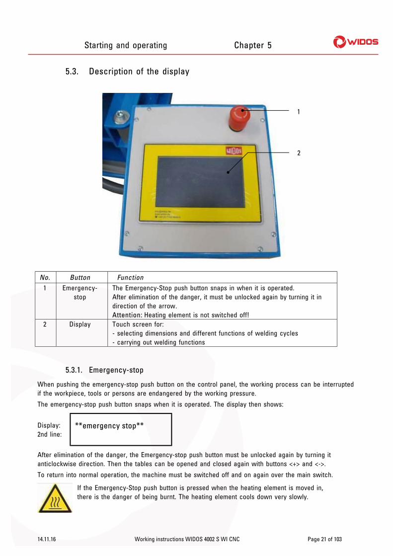
5.3. Description of the display
No. Button Function 1 Emergency-
stop The Emergency-Stop push button snaps in when it is operated. After elimination of the danger, it must be unlocked again by turning it in direction of the arrow. Attention: Heating element is not switched off!
2 Display Touch screen for: - selecting dimensions and different functions of welding cycles - carrying out welding functions
5.3.1. Emergency-stop
When pushing the emergency-stop push button on the control panel, the working process can be interrupted if the workpiece, tools or persons are endangered by the working pressure.
The emergency-stop push button snaps when it is operated. The display then shows:
Display: 2nd line:
**emergency stop**
After elimination of the danger, the Emergency-stop push button must be unlocked again by turning it anticlockwise direction. Then the tables can be opened and closed again with buttons <+> and <->.
To return into normal operation, the machine must be switched off and on again over the main switch.
If the Emergency-Stop push button is pressed when the heating element is moved in, there is the danger of being burnt. The heating element cools down very slowly.
1
2

Starting and operating Chapter 5
14.11.16 Working instructions WIDOS 4002 S WI CNC Page 22 of 103
5.4. Buttons on the touch screen
Three variations are possible:
Dark button: button inactive, cannot be pressed
Light button: button active, for manual working step
Light, animated button: advice for next working step
5.4.1. Small symbol buttons
Abort
Forward with: (INSERT PIPES CLEANING)
Manual driving apart No (red)
Diagnosis Parameter
Welding standard Plus
Information Verifying off
Yes (green) Verifying on (black)
Copy
Identify carriage automatically, (option, with digital way measuring system)
blank backwards
Minus Manual driving together
Next construction stage Check oil level
Next

Starting and operating Chapter 5
14.11.16 Working instructions WIDOS 4002 S WI CNC Page 23 of 103
5.4.2. Large symbol buttons
Cooling Button (colored) active
Bead-up Button (black) inactive
Heat-up Weld no.
Driving apart OK (green)
Unclamping Not OK (red)
Initial position Select parameters
Drag pressure measuring Ramp, pressure built-up
Check (black) Start
Insert heating element Change-over
Check heating temperature Check mismatch
Turn planer Pressure build-up – please check if pipes are slipping through
Insert planer

Starting and operating Chapter 5
14.11.16 Working instructions WIDOS 4002 S WI CNC Page 24 of 103
5.5. Accessories for reading data in and out (option)
5.5.1. Legitimacy cards
There are 3 different types of cards which are accepted by the card reader:
(1) With each supplied machine a general legitimacy card (5 pieces) is basically supplied with. It is of white color and gives the legitimating to operate all functions (including special functions).
(2) Pipe data card: on this card all dimensions of a pipe are memorized (parameters are stored in the control unit). For ordering the card, the pipe diameter, the pipe wall thickness and the material should be specified.
(3) Optionally, a gas legitimacy card (yellow) can be supplied. With this card, no changes can be made in the system. The computer will ask automatically for a pipe data card for setting the pipe data.
Protect the cards from humidity and dirtiness. Do not bend the cards or expose them to high magnetic fields. The card is not transferable.
5.5.2. Bar code scanner
For reading the bar code in, put the scanner with the scanning surface vertically over the bar code and press the activation button on the bottom side. Reading in is confirmed with a beep tone.
Scanner is ready when the scanning surface is glowing red.
5.5.3. SD card and drive
The machine is equipped with a SD card drive.
The machine stores the welding data in the internal memory as well as on the SD card if there is one plugged in.
The SD card with 64 MB of memory stores appr. 32,000 weldings.
The SD card must be formatted by “FAT 16” necessarily before usage.
Insert the card with its inscription to the top carefully and with low force into the reading unit.
The card can be read out with a WICON program.
The card may not be bent, opened, overheated and become wet!
Please only use SD cards purchased from WIDOS. We will not be liable for any cards from other manufacturers!
Starting and operating Chapter 5
14.11.16 Working instructions WIDOS 4002 S WI CNC Page 25 of 103
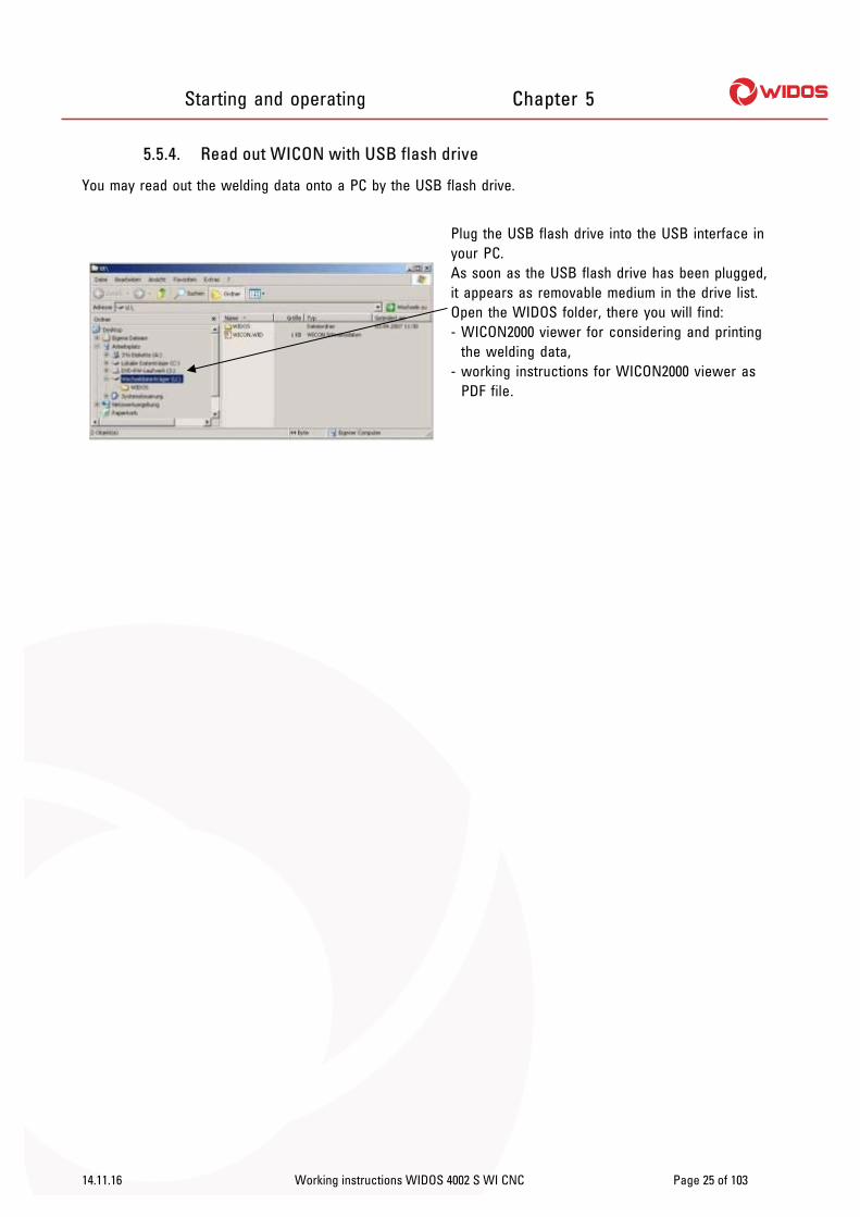
5.5.4. Read out WICON with USB flash drive
You may read out the welding data onto a PC by the USB flash drive.
Plug the USB flash drive into the USB interface in your PC. As soon as the USB flash drive has been plugged, it appears as removable medium in the drive list. Open the WIDOS folder, there you will find: - WICON2000 viewer for considering and printing
the welding data, - working instructions for WICON2000 viewer as
PDF file.

Starting and operating Chapter 5
14.11.16 Working instructions WIDOS 4002 S WI CNC Page 26 of 103
5.6. Switching the WI – CNC® 1.1 / 1.3 on
Actuate the main switch at the WI – CNC® 1.1 / 1.3 and (chapter: Fehler! Verweisquelle konnte nicht gefunden werden., No.: 3). As soon as the switch is activated, the display illuminates (the computer is being initialized).
Indication: current software version,
Indication: serial number
Indication: validity until next maintenance
Either: Identify with the (optional) scanner and corresponding bar code on the legitimacy card. Or: Press: < > and enter the 4-digit identifying information with the keypad. Press < > afterwards.
Enter bar code with the keypad. Confirm bar code with: < >.

Starting and operating Chapter 5
14.11.16 Working instructions WIDOS 4002 S WI CNC Page 27 of 103
Basic menu: Indication: currently connected machine type
1030 = free weldings in RAM / max. appr. 32,000 memory space available at USB (or in case of: ▬ = no memory available at USB) Indication: user name (bar code)
In the basic menu you may:
Either: drive the machine into initial position by pressing: < >. Or: identify the machine type with: < >.
5.6.1. Select machine type with digital way-measuring device
Indication: current software version,
Indication: serial number
Indication: validity until next maintenance
Press < >, the machine identifies automatically.

Starting and operating Chapter 5
14.11.16 Working instructions WIDOS 4002 S WI CNC Page 28 of 103
This error message appears if no way-measuring system is available and no basic machine is connected.
Press: < > in order to identify the machine manually.
Indication: all machine types,
the selected machine type is highlighted.
Confirm the selected machine type with: < >.
Indication: currently connected machine type
Indication: free memory space in RAM / on USB device
Indication: user name

Starting and operating Chapter 5
14.11.16 Working instructions WIDOS 4002 S WI CNC Page 29 of 103
Basic menu, You may:
select dimensions with: < >
drive carriage apart with: < >
drive carriage together with: < >
5.6.2. Define dimension
Basic menu, You may:
select dimensions with: < >
drive carriage apart with: < >
drive carriage together with: < >
Press < > in order to select dimensions.
Image only appears if you press < >:
Scroll the text with <>, it is explained on the screen.
Press < > in order to exit the help menu

Starting and operating Chapter 5
14.11.16 Working instructions WIDOS 4002 S WI CNC Page 30 of 103
Indication: current dimensions
Select material with < / >: PE / PP / SLM30 or lab material.
Select pipe outer diameter with < / >.
Select wall thickness with < / >, the current SDR value appears automatically. Temperature is indicated according to DVS specification, cannot be changed.
Select welding method with < >: DVS / NEN / LAB you want to weld with.
Indication: welding standard possibilities,
the selected welding standard is highlighted.
Confirm welding standard with < >.
No = < >; Yes = < >;
Either: Confirm selected welding standard with < >. Or: Press < > and select another welding standard.
Starting and operating Chapter 5
14.11.16 Working instructions WIDOS 4002 S WI CNC Page 31 of 103
Indication: current dimensions
Either: Confirm settings with < >. Or: Press < > for further settings.
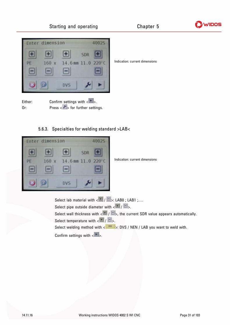
5.6.3. Specialties for welding standard >LAB<
Indication: current dimensions
Select lab material with < / >: LAB0 ; LAB1 ;….
Select pipe outside diameter with < / >.
Select wall thickness with < / >, the current SDR value appears automatically.
Select temperature with < / >.
Select welding method with < >: DVS / NEN / LAB you want to weld with.
Confirm settings with < >.

Starting and operating Chapter 5
14.11.16 Working instructions WIDOS 4002 S WI CNC Page 32 of 103
Indication: current dimensions
Select „edit material name“ with < >.
Select pipe outside diameter with < / >.
Select wall thickness with < / >, the current SDR value appears automatically.
Select temperature with < / >.
Select welding method with < >: DVS / NEN / LAB you want to weld with.
Confirm settings with < >.
Indication: current material name
You may change the material name by adapting the entry via keypad. You may confirm it with < > afterwards.
Indication: change parameters
By tapping on each parameter you may change each one especially as you wish.

Starting and operating Chapter 5
14.11.16 Working instructions WIDOS 4002 S WI CNC Page 33 of 103
Indication: change parameters (bead-up)
Select bead-up time with < / >.
Select bead-up pressure with < / >.
Confirm settings with < >.
Indication: change parameters (heat-up)
Select heat-up time with < / >.
Select heat-up pressure with < / >.
Confirm settings with < >.
Indication: change parameters (change-over)
Select change-over time with < / >.
Confirm settings with < >.

Starting and operating Chapter 5
14.11.16 Working instructions WIDOS 4002 S WI CNC Page 34 of 103
Indication: change parameters (cooling 1)
Select cooling time 1 with < / >.
Select cooling pressure 1 with < / >.
Confirm settings with < >.
Indication: change parameters (cooling 2)
Select cooling time 2 with < / >.
Select cooling pressure 2 with < / >.
Confirm settings with < >.

Starting and operating Chapter 5
14.11.16 Working instructions WIDOS 4002 S WI CNC Page 35 of 103
5.6.4. How to enter further settings like traceability, ½ cooling time or RAM > USB
Indication: current dimensions
Press < > for further settings.
Press < > in order to select traceability, button changes to < >.
Press < > in order to select ½ cooling time, button changes to < >.
Press < > in order to copy all existing weldings from RAM to the connected device at the USB interface.
Either: Exit further settings with < >.
Or: Enter diagnosis menu with < >.
Or: Press < > for further settings: time, date and buzzer.

Starting and operating Chapter 5
14.11.16 Working instructions WIDOS 4002 S WI CNC Page 36 of 103
5.6.4.1. How to set date, time, buzzer and language
Press < >
Indication: different languages,
by selecting the language it is highlighted
Volume: Tap on the volume bar depending on the volume, the volume bar refreshes,
or tap on < > in order to disable the buzzer, button changes to < >.
Language: Tap on the desired language, the language is highlighted.
Time + date: Press < > in order to set time and date.
Indication: date and time
Set day, month and year as well as hour and minute with < / >.
Confirm it with < >.

Starting and operating Chapter 5
14.11.16 Working instructions WIDOS 4002 S WI CNC Page 37 of 103
Indication: different languages,
by selecting the language it is highlighted
Confirm it with < >.
Basic menu:
Indication: current machine type
Indication: current date and time
Indication: user name

Starting and operating Chapter 5
14.11.16 Working instructions WIDOS 4002 S WI CNC Page 38 of 103
5.7. Welding with the WI–CNC® 1.1 - 1.3
The WI–CNC® 1.1 - 1.3 is activated (chapter: 5.6), and the basic machine is identified (chapter: 5.6.1 / Fehler! Verweisquelle konnte nicht gefunden werden.).
Basic menu
Indication: current machine type
Indication: current date and time
Indication: user name
Press < > in order to start welding.
In case you have a basic machine without digital way-measuring device, the following error message appears:
Confirm the error message with < >.
In case you have not driven the basic machine into initial position while activating it, the following error message appears:
Confirm the error message with < >.

Starting and operating Chapter 5
14.11.16 Working instructions WIDOS 4002 S WI CNC Page 39 of 103
Basic menu:
Indication: current machine type
Indication: current date and time
Indication: user name
Go back with < > and drive the machine into initial position, otherwise welding is not possible.
Indication: current dimensions
Check dimensions if they match the pipes. Confirm settings with < >.
Indication: current dimensions
Check dimensions if they match the pipes. Confirm settings with < >.

Starting and operating Chapter 5
14.11.16 Working instructions WIDOS 4002 S WI CNC Page 40 of 103
Select current weather condition on the left side.
Select protective measure on the right side and carry it out at the machine. Either: Confirm settings with < >. Or: Confirm settings with < >, the last project name and next weld number register
automatically. Then continue with: (page: 37).
Indication: current project name – number 1
Indication: current project name
Either: Change indicated project name with the keypad.
Or: Press < >, you may select project name – number 2…5 and use or change it if necessary.
Indication: current weld number,
the weld number is stored with relation to the project
You may change the weld number with the keypad, the next welding is counted forward automatically. Confirm weld number with < >.

Starting and operating Chapter 5
14.11.16 Working instructions WIDOS 4002 S WI CNC Page 41 of 103
In case you have connected a heating element with PLC function and if the current temperature has not reach the nominal temperature, the following appears:
Indication: pipe dimension, time + outside temperature (optional)
Indication: nominal temperature (orange) and current temperature (red)
Confirm error message with < >.
Indication: pipe dimension, time + outside temperature (optional)
Indication: nominal temperature (orange) and current temperature (red) You may drive the carriage apart and together
with < / >.
As soon as the heating element is heated up to nominal temperature, the following appears:
Indication: pipe dimension, time + outside temperature (optional)
Indication: nominal temperature (orange) and current temperature (red) You may drive the carriage apart and together
with < / >.
Press < > (flashing).

Starting and operating Chapter 5
14.11.16 Working instructions WIDOS 4002 S WI CNC Page 42 of 103
This message appears only if the basic machine is not completely driven apart:
Indication: pipe dimension, time + outside temperature (optional)
Indication: nominal pressure: ps, drag pressure: p0, current pressure: pi and current temperature
Press < > in order to drive basic machine completely apart.
Indication: pipe dimension, time + outside temperature (optional)
Indication: nominal pressure: ps, drag pressure: p0, current pressure: pi and current temperature
Fix the pipes in the clamping rings and clean the pipe ends. Confirm with < >.
Indication: pipe dimension, time + outside temperature (optional)
Indication: nominal pressure: ps, drag pressure: p0, current pressure: pi and current temperature
Press < > in order to start drag pressure measuring.

Starting and operating Chapter 5
14.11.16 Working instructions WIDOS 4002 S WI CNC Page 43 of 103
Indication: pipe dimension, time + outside temperature (optional)
Indication: nominal pressure: ps, drag pressure: p0, current pressure: pi and current temperature
The drag pressure is being measured, afterwards the following appears automatically:
In case you have clamped the pipes too far in, the following appears:
Indication: pipe dimension, time + outside temperature (optional)
Confirm error message with < >. Afterwards release the clamping rings and clamp one or both pipes farther out.
Indication: pipe dimension, time + outside temperature (optional)
Indication: nominal pressure: ps, drag pressure: p0, current pressure: pi and current temperature
Press < > in order to start drag pressure measuring.

Starting and operating Chapter 5
14.11.16 Working instructions WIDOS 4002 S WI CNC Page 44 of 103
Indication: pipe dimension, time + outside temperature (optional)
Indication: nominal pressure: ps, drag pressure: p0, current pressure: pi and current temperature
The machine is being calibrated, afterwards the following appears automatically:
Indication: pipe dimension, time + outside temperature (optional)
Indication: nominal pressure: ps, drag pressure: p0, current pressure: pi and current temperature
Insert the planer into the machine in-between the pipe ends and let it snap in the front. Press < >, the planer starts rotating as long as you keep it pressed.
Indication: pipe dimension, time + outside temperature (optional)
Indication: nominal pressure: ps, drag pressure: p0, current pressure: pi and current temperature
Cut pipes ends until a circular chip has formed running around the pipes and < > is flashing. Then release < >.

Starting and operating Chapter 5
14.11.16 Working instructions WIDOS 4002 S WI CNC Page 45 of 103
Indication: pipe dimension, time + outside temperature (optional)
Indication: nominal pressure: ps, drag pressure: p0, current pressure: pi and current temperature
Take the planer out of the machine and put it back into the reception box. Remove the chips created without touching the welding surfaces.
Either: The pipe ends are plane; then press < > in order to start mismatch checkup; the machine drives the pipes ends together.
Or: The pipe ends are not plane; then reinsert the planer into the basic machine and repeat planing with < >.
Indication: pipe dimension, time + outside temperature (optional)
Indication: nominal pressure: ps, drag pressure: p0, current pressure: pi and current temperature
Indication: pipe dimension, time + outside temperature (optional)
Indication: nominal pressure: ps, drag pressure: p0, current pressure: pi and current temperature
Check mismatch at the abutting pipe ends; mismatch must not exceed 10% of the wall thickness according to DVS.
The gap must not exceed 0.5 mm for pipes with OD ≤ 355 mm and 1.0 mm for pipes with OD 400 – 630 mm.
In case mismatch is not correct, you can compensate it by changing the clamping of the pipes; afterwards necessarily repeat planing with: < >. In case mismatch is correct, you may:
Either: Continue welding with < >,

Starting and operating Chapter 5
14.11.16 Working instructions WIDOS 4002 S WI CNC Page 46 of 103
Or: Carry out a test pressure with: < > in order to check the slipping of the pipes.
Indication: pipe dimension, time + outside temperature (optional)
Indication: nominal pressure: ps, drag pressure: p0, current pressure: pi and current temperature
Keep < > pressed; the machine will build up the adjusted pressure. Simultaneously check nominal and current pressure.
Or: The pipes are slipping at a current pressure ≤ nominal pressure; then you must increase the clamping of the pipes and repeat planing with < >.
This message appears only if machine has a GPS receiver (optional).
Indication: pipe dimension, time + outside temperature (optional)
Indication: nominal pressure: ps, drag pressure: p0, current pressure: pi and current temperature
Indication: GPS coordinates
Indication: pipe dimension, time + outside temperature (optional)
Indication: nominal pressure: ps, drag pressure: p0, current pressure: pi and current temperature
Insert the heating element into the machine and confirm it with < >.

Starting and operating Chapter 5
14.11.16 Working instructions WIDOS 4002 S WI CNC Page 47 of 103
Indication: pipe dimension, time + outside temperature (optional)
Indication: nominal pressure: ps, drag pressure: p0, current pressure: pi and current temperature
Indication: nominal bead-up travel [mm]
Once bead-up is complete, pressure is reduced and heat-up starts.
Indication: pipe dimension, time + outside temperature (optional)
Indication: nominal pressure: ps, drag pressure: p0, current pressure: pi and current temperature
Indication: elapsed heat-up [s]
The end of the heat-up is signaled by beeps; the following appears:
Indication: pipe dimension, time + outside temperature (optional)
Indication: nominal pressure: ps, drag pressure: p0, current pressure: pi and current temperature
Indication: elapsed change-over [s]
The machine drives apart.
Either: You remove the heating element from the machine during change-over putting it back into the reception box.

Starting and operating Chapter 5
14.11.16 Working instructions WIDOS 4002 S WI CNC Page 48 of 103
Or: You do not remove the heating element during change-over; then the following appears:
Confirm error message with < >; welding is aborted.
Indication: machine type
Indication: date and time
Indication: user name
Once change-over has finished, the machine will drive the pipes together.
Indication: pipe dimension, time + outside temperature (optional)
Indication: nominal pressure: ps, drag pressure: p0, current pressure: pi and current temperature
Indication: elapsed cooling [s]
Indication: pipe dimension, time + outside temperature (optional)
Indication: nominal pressure: ps, drag pressure: p0, current pressure: pi and current temperature
Indication: elapsed cooling 2 [min]
Starting and operating Chapter 5
14.11.16 Working instructions WIDOS 4002 S WI CNC Page 49 of 103
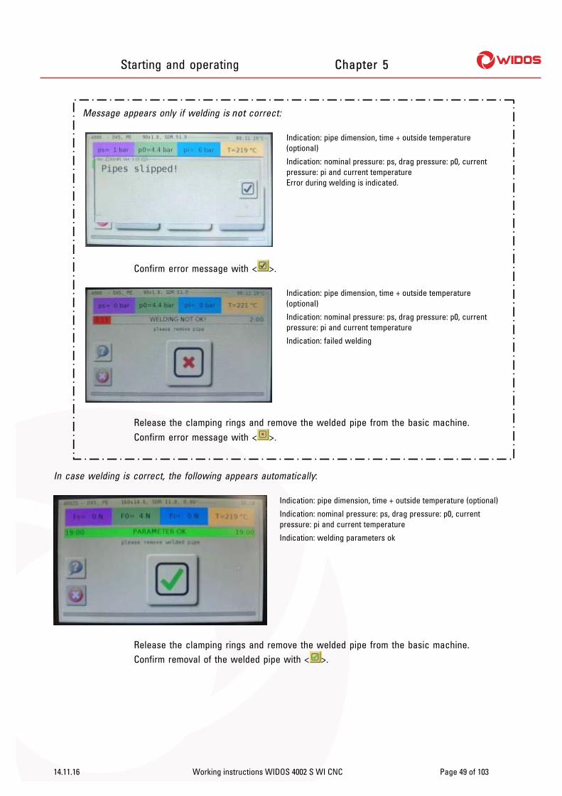
Message appears only if welding is not correct:
Indication: pipe dimension, time + outside temperature (optional)
Indication: nominal pressure: ps, drag pressure: p0, current pressure: pi and current temperature Error during welding is indicated.
Confirm error message with < >.
Indication: pipe dimension, time + outside temperature (optional)
Indication: nominal pressure: ps, drag pressure: p0, current pressure: pi and current temperature
Indication: failed welding
Release the clamping rings and remove the welded pipe from the basic machine. Confirm error message with < >.
In case welding is correct, the following appears automatically:
Indication: pipe dimension, time + outside temperature (optional)
Indication: nominal pressure: ps, drag pressure: p0, current pressure: pi and current temperature
Indication: welding parameters ok
Release the clamping rings and remove the welded pipe from the basic machine. Confirm removal of the welded pipe with < >.

Starting and operating Chapter 5
14.11.16 Working instructions WIDOS 4002 S WI CNC Page 50 of 103
Indication: machine type
Indication: date and time
Indication: user name
Welding is completed.
5.7.1. Copy internal data onto SD card and delete internal data (RAM)
Connect the USB stick or any other memory medium to one of the USB interfaces (chapter: Fehler! Verweisquelle konnte nicht gefunden werden., no. 4).
Indication: current dimensions
Press < > for further settings.
Press < > in order to copy all existing weldings from the RAM onto the connected device at the USB interface.

Starting and operating Chapter 5
14.11.16 Working instructions WIDOS 4002 S WI CNC Page 51 of 103
In case there is no stick / memory media plugged into the USB interface, the following appears:
Plug stick / memory media into an USB interface and confirm error message with < >.
In case no welding is stored in the RAM; the following appears:
Confirm error message with < >.
No = < >; Yes = < >
Either: Press < > and delete the RAM memory.
Or: Press < > and do not delete the RAM memory.

Starting and operating Chapter 5
14.11.16 Working instructions WIDOS 4002 S WI CNC Page 52 of 103
5.8. Setting the welding angle
Image showing right clamping tool
In order to adjust the angle, first remove screw 3. Detach screws 1 and 2, then turn the clamping tool around the rotary point onto the desired angle. Markings have been fixed to the table for angles 11.25° and 15°, other angles must be adjusted by goniometer. Afterwards retighten screws 1 and 2.
5.8.1. Welding of T-piece 90°
T – pieces with 90° (and cross-pieces optional) up to OD = 250 mm can be welded.
The optional available T-piece clamping tools are screwed on with the corresponding adapter plates just as the clamping tools that belong to the standard equipment.
Rotary point for clamping tool
Planer Heating element
T–piece tools

Starting and operating Chapter 5
14.11.16 Working instructions WIDOS 4002 S WI CNC Page 53 of 103
5.8.2. Drillings at the table
The clamping tool is fixed on one side by means of a centering bolt. It serves as gravity center for a possible angle setting.
The left clamping tool can displaced by 20 mm to the left.
At the slotted hole on the clamping tool, any angles from 0-15° can be adjusted. For the exact setting of 11,25° and 15°, figure stamps are existing.
Moving direction
Angle marking for clamping
tool displaced
Pivot for clamping tool Pivot for clamping tool displaced
Fixing hole
Inner edge left table
Fixing hole for clamping tool displaced
Angle marking
WIDOS Einsteinstr. 5 Phone +49 71 52 99 39 0 Wilhelm Dommer Söhne D-71254 Ditzingen Fax +49 71 52 99 39 40 GmbH info @ widos.de Internet: www.widos.de
14.11.2016 Working instructions WIDOS 4002 S WI CNC Page 54 of 103
6. Equipment care / maintenance / repair
Goal of the chapter is: Keeping the nominal state and the operation capacity of the apparatus.
Increasing the efficiency by avoiding non-planned outage.
Efficient planning of the maintenance work and the maintenance tools.
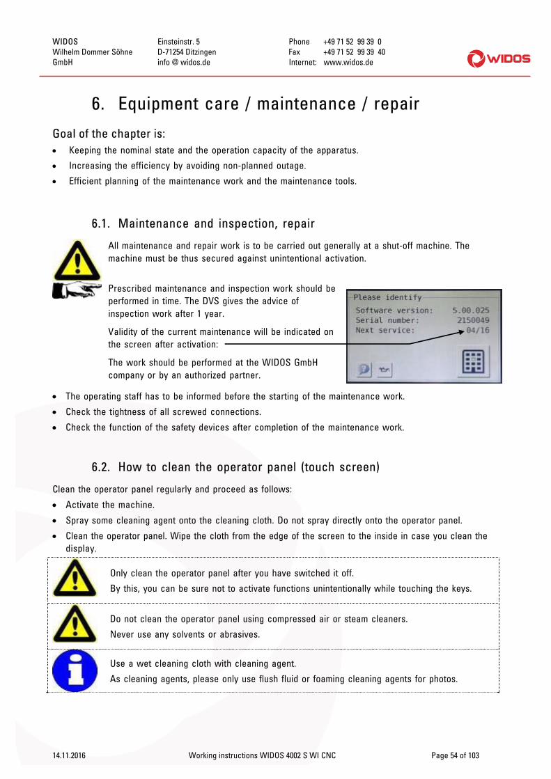
6.1. Maintenance and inspection, repair
All maintenance and repair work is to be carried out generally at a shut-off machine. The machine must be thus secured against unintentional activation.
Prescribed maintenance and inspection work should be performed in time. The DVS gives the advice of inspection work after 1 year.
Validity of the current maintenance will be indicated on the screen after activation:
The work should be performed at the WIDOS GmbH company or by an authorized partner.
The operating staff has to be informed before the starting of the maintenance work.
Check the tightness of all screwed connections.
Check the function of the safety devices after completion of the maintenance work.
6.2. How to clean the operator panel (touch screen)
Clean the operator panel regularly and proceed as follows:
Activate the machine.
Spray some cleaning agent onto the cleaning cloth. Do not spray directly onto the operator panel.
Clean the operator panel. Wipe the cloth from the edge of the screen to the inside in case you clean the display.
Only clean the operator panel after you have switched it off.
By this, you can be sure not to activate functions unintentionally while touching the keys.
Do not clean the operator panel using compressed air or steam cleaners.
Never use any solvents or abrasives.
Use a wet cleaning cloth with cleaning agent.
As cleaning agents, please only use flush fluid or foaming cleaning agents for photos.

Equipment care /maintenance / repair Chapter 6
14.11.2016 Working instructions WIDOS 4002 S WI CNC Page 55 of 103
6.3. Fuses in the switch cabinet
Nr. Bezeichnung / Funktion FC1 Main fuse FC2 Fuse control QA1 Contactor emergency stop
QA40 Easy start planer KF1 Control emergency stop
XD01 Feeding KF2 Rear panel adapter QB1 Main switch
QA21 Semiconductor relay heating element L1 QA22 Semiconductor relay heating element L2 TB11 Servor control table TB1 24 V- switch supply unit
KF106 Servo enable FC3 Fuse control unit 24 V
6.4. Safety switch and end switch at tghe machine
1 safty switch: release handle heating element (BG21) 1 end switch: reference point table (BG111)
Check end switch and safety switch regularly for correct functioning (and optionally for being soiled).
TB11
KF2
FC1 / FC2 QA1 KF1
TB1
KF106 / FC3
XD01
QB1
QA22
QA21

Equipment care /maintenance / repair Chapter 6
14.11.2016 Working instructions WIDOS 4002 S WI CNC Page 56 of 103
6.5. Clamping elements
In order to warrant a long service time you should regularly clean and lubricate the threaded spindles and joint pieces for the pipe clamping.
6.6. Planer
Verify the cutting performance of the planer blades, replace blades if necessary (both-sided sharpening, max. chip thickness = 0,2 mm!)
Check the tension of the driving chain in the planer from time to time and lubricate the chain, to do it unscrew the planer housing. The chain should be hand-tight.
6.7. Storage
Store the hydraulic control unit in a dry room.
6.8. Disposal
At the end of their life time, the apparatus and the wear parts have to be disposed of properly and non-polluting, and in accordance with the national laws of waste disposal.

WIDOS Einsteinstr. 5 Phone +49 71 52 99 39 0 Wilhelm Dommer Söhne D-71254 Ditzingen Fax +49 71 52 99 39 40 GmbH info @ widos.de Internet: www.widos.de
14.11.2016 Working instructions WIDOS 4002 S WI CNC Page 57 of 103
7. Transport
7.1. WI-CNC® 1.1 / 1.3
The transport of the WI-CNC® 1.1 / 1.3 is carried out:
Either: in a transport box together with a WIDOS welding machine.
Or: in a separate transport box.
The transport box is more suitable for longer transports thanks to their compact design.
Make sure that the device is not tilted too much in order that oil cannot leak out.
Protect the hydraulic control unit from heavy shocks.
Make sure that the box cover is closed correctly.
During the construction of the transport box a stress was put on a light-weight construction.
Take utmost care when using automatic handling and carrying machines.
7.2. 4002 S CNC
Swing heating element and planer between the shut clamping tools. Protect the front faces of planer and heating element e.g. with cardboard or plastic film.
Make sure that the machine is not exposed to shocks, especially when being transported with lifting devices etc.
Handle the machine with care, especially take care of electric cables.

WIDOS Einsteinstr. 5 Phone +49 71 52 99 39 0 Wilhelm Dommer Söhne D-71254 Ditzingen Fax +49 71 52 99 39 40 GmbH E-Mail: info @ widos.de Internet: www.widos.de
14.11.2016 Working instructions WIDOS 4002 S WI CNC Page 58 of 103
8. Electric and pneumatic diagrams
8.1. Pneumatic diagram
Spare parts list Chapter 9
14.11.2016 Working instructions WIDOS 4002 S WI CNC Page 59 of 103
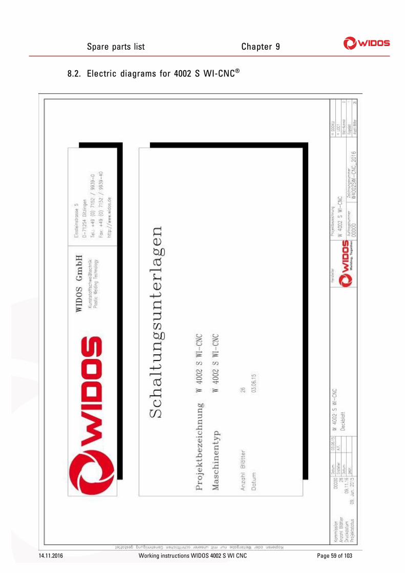
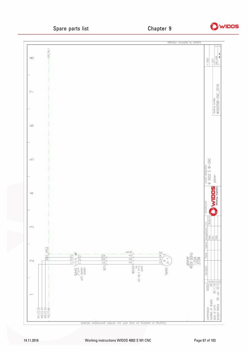
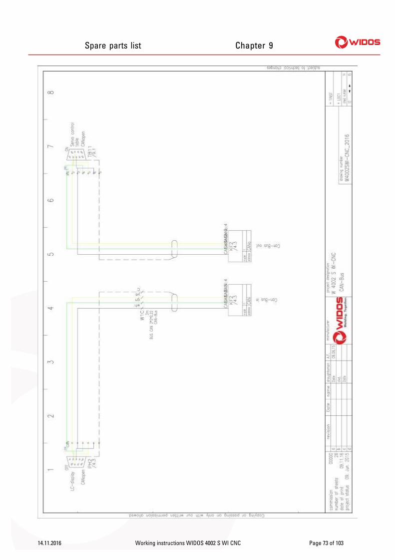
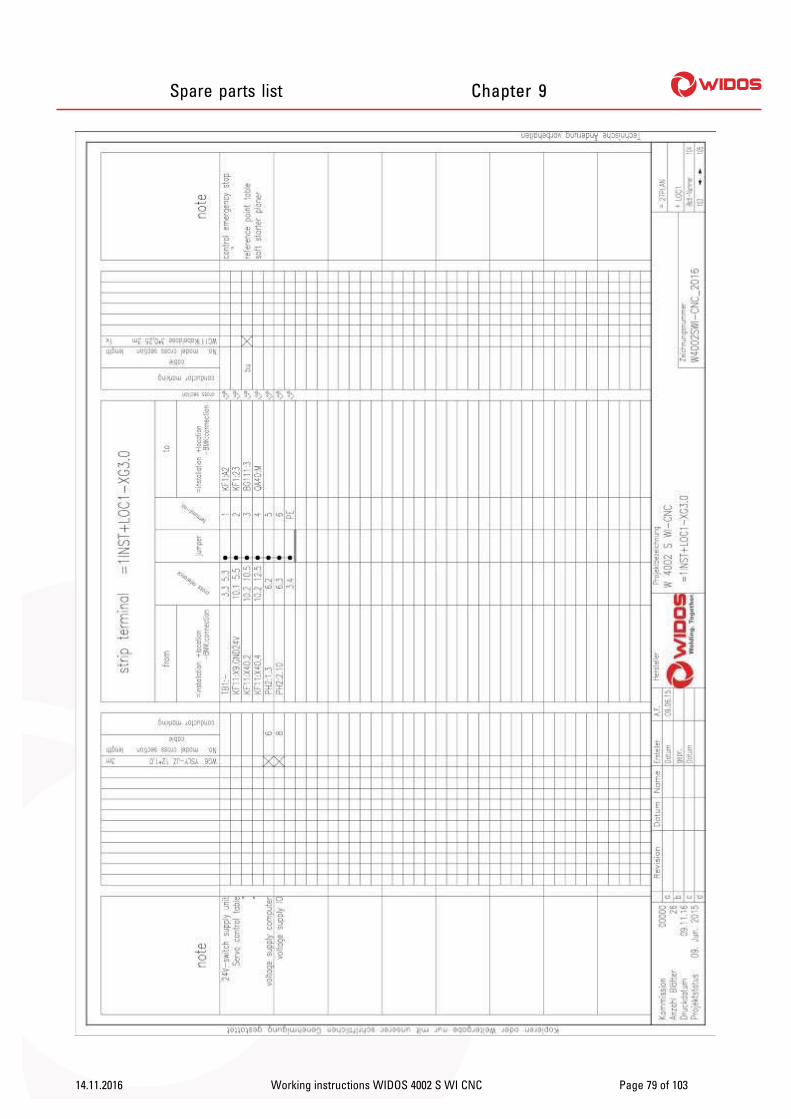
8.2. Electric diagrams for 4002 S WI-CNC®

Spare parts list Chapter 9
14.11.2016 Working instructions WIDOS 4002 S WI CNC Page 60 of 103

Spare parts list Chapter 9
14.11.2016 Working instructions WIDOS 4002 S WI CNC Page 61 of 103

Spare parts list Chapter 9
14.11.2016 Working instructions WIDOS 4002 S WI CNC Page 62 of 103

Spare parts list Chapter 9
14.11.2016 Working instructions WIDOS 4002 S WI CNC Page 63 of 103

Spare parts list Chapter 9
14.11.2016 Working instructions WIDOS 4002 S WI CNC Page 64 of 103

Spare parts list Chapter 9
14.11.2016 Working instructions WIDOS 4002 S WI CNC Page 65 of 103

Spare parts list Chapter 9
14.11.2016 Working instructions WIDOS 4002 S WI CNC Page 66 of 103
Spare parts list Chapter 9
14.11.2016 Working instructions WIDOS 4002 S WI CNC Page 67 of 103

Spare parts list Chapter 9
14.11.2016 Working instructions WIDOS 4002 S WI CNC Page 68 of 103

Spare parts list Chapter 9
14.11.2016 Working instructions WIDOS 4002 S WI CNC Page 69 of 103

Spare parts list Chapter 9
14.11.2016 Working instructions WIDOS 4002 S WI CNC Page 70 of 103

Spare parts list Chapter 9
14.11.2016 Working instructions WIDOS 4002 S WI CNC Page 71 of 103

Spare parts list Chapter 9
14.11.2016 Working instructions WIDOS 4002 S WI CNC Page 72 of 103
Spare parts list Chapter 9
14.11.2016 Working instructions WIDOS 4002 S WI CNC Page 73 of 103

Spare parts list Chapter 9
14.11.2016 Working instructions WIDOS 4002 S WI CNC Page 74 of 103

Spare parts list Chapter 9
14.11.2016 Working instructions WIDOS 4002 S WI CNC Page 75 of 103

Spare parts list Chapter 9
14.11.2016 Working instructions WIDOS 4002 S WI CNC Page 76 of 103

Spare parts list Chapter 9
14.11.2016 Working instructions WIDOS 4002 S WI CNC Page 77 of 103

Spare parts list Chapter 9
14.11.2016 Working instructions WIDOS 4002 S WI CNC Page 78 of 103
Spare parts list Chapter 9
14.11.2016 Working instructions WIDOS 4002 S WI CNC Page 79 of 103

Spare parts list Chapter 9
14.11.2016 Working instructions WIDOS 4002 S WI CNC Page 80 of 103

Spare parts list Chapter 9
14.11.2016 Working instructions WIDOS 4002 S WI CNC Page 81 of 103

Spare parts list Chapter 9
14.11.2016 Working instructions WIDOS 4002 S WI CNC Page 82 of 103

Spare parts list Chapter 9
14.11.2016 Working instructions WIDOS 4002 S WI CNC Page 83 of 103

Spare parts list Chapter 9
14.11.2016 Working instructions WIDOS 4002 S WI CNC Page 84 of 103

WIDOS Einsteinstr. 5 Phone +49 71 52 99 39 0 Wilhelm Dommer Söhne D-71254 Ditzingen Fax +49 71 52 99 39 40 GmbH E-Mail: info @ widos.de Internet: www.widos.de
14.11.2016 Working instructions WIDOS 4002 S WI CNC Page 85 of 103
9. Spare parts list
9.1. Basic machine
60 - 62
38 - 39
47 28 - 30
48 - 50
54 - 56
45 - 46
59
41 - 44
51 - 53 32 - 37
26 - 27
57 - 58 40
31
9 - 10
5 - 8
24 - 25
11 - 15
1 - 2
3 - 4
23
16 - 18
19 - 22
9 - 10

Spare parts list Chapter 9
14.11.2016 Working instructions WIDOS 4002 S WI CNC Page 86 of 103
Servo drive: (Bottom side for left carriage in disassembled condition)
(Bottom side right carriage) (Bottom side right carriage, side view)
63 - 64
65 - 66
67 - 69
70
71 - 73
74
79 - 80
92 - 93
88
89 - 91
82
83 - 84 85 - 87
75 - 78 81

Spare parts list Chapter 9
14.11.2016 Working instructions WIDOS 4002 S WI CNC Page 87 of 103
94 - 95
96 - 97
98

Spare parts list Chapter 9
14.11.2016 Working instructions WIDOS 4002 S WI CNC Page 88 of 103
(Basic machine rear view)
99
100
101 - 102

Spare parts list Chapter 9
WIDOS 4002 S WI CNC Basic unit
Pos. Name Piece Order no. 1 Frontal girder 1 0231022 Rivet nut M 10 5 N10023 Rear girder 1 0231044 Rivet nut M 10 5 N10025 Angle 2 0231036 Pan-head screw M 10x25 DIN 912 8 0912J0257 Washer M10 DIN 125 8 0125J8 Basic frame 1 1721319 Clamping lever (threaded length 30 mm) 2 BM10030
10 Straight pin 8x120 DIN 6325 2 6325H12011 Swivel plate for operator console 1 172235212 Swivel holder for operator console 1 172235313 Swivel bolt for operator console 1 172235414 Pan-head screw M 12x20 DIN7984 2 7984L02015 Washer M 12 DIN 9021 2 9021L16 Covering in front 1 17231817 Pan-head screw M 5 x 1225 DIN 912 4 0912E01218 Washer M 5 DIN 9021 4 9021E19 Flat-head screw M4x30 DIN 965 2 0965C03020 Collar M4 2 ROSM421 Washer M4 DIN 125 2 0125D22 Lock nut M 4 DIN 985 2 0985D23 Position switch 1 ES1030523 Cover for electric box 1 17223924 Lock 2 J5402ALL25 Shaft (d = 25, l= 275 mm) 1 02312026 Guide bearing 1 LKH254027 Pan-head screw M 10x90 DIN 912 2 0912J09028 Pan-head screw M 10x70 DIN 912 4 0912J07029 Plate, horizontal movement 1 02310830 Slide, right 1 02310631 Guide rod 2 02310732 Pan-head screw M 10x40 DIN 912 2 0912J04033 Grub screw M 6x10 DIN 913 1 0913F01034 Thread insert M 10 4 GEW-M1035 Counter nut M 10 DIN 985 2 0985J36 Washer M 10 DIN 125 2 0125J37 Pull off claw for heating element (fixed) 1 17250638 Pan-head screw M6x20 DIN 912 2 0912F02039 Washer M6 DIN 125 2 0125F40 Slide for linear guide 4 L20ELZ41 Linear guide 2 L2070042 Fitting cap 24 L20501
14.11.2016 Working Instructions WIDOS 4002 S WI CNC Page 89 / 1 of 103

Spare parts list Chapter 9
WIDOS 4002 S WI CNC Basic unit
Pos. Name Piece Order no.
43 Pan-head screw M 5x16 DIN 912 24 0912E01644 Parallel pin M 5x18 DIN 6325 4 6325E01845 Chips skirtboard for ball screw 1 17212346 Pan-head screw M6x12 DIN 912 2 0912F01247 Pan-head screw M 8x55 DIN 912 16 0912H05548 Pull off claw for heating element (movable) 1 17250749 Pan-head screw M6x12 DIN 912 2 0912F01250 Washer M6 DIN 125 2 0125F51 Slide, left 1 02310552 Thread insert M 12 short 2 GEWK-M1253 Thread insert M 12 5 GEW-M1254 Linear guide with slide 2 L3060055 Pan-head screw M 8x30 DIN 912 16 0912H03056 Cap for linear guide 16 L3060157 Stop pin 2 02410558 Washer M 10 DIN 125 2 0125J59 Chips skirtboard 1 17231560 Covering behind 1 17233461 Hexagon nut M8 DIN 934 2 0934F62 Washer M8 DIN 9021 2 9021F63 Girder for load cell 1 17211764 Pan-head screw M5x16 DIN 912 3 0912E01665 Linear guide carriage 2 L20FLZ66 Linear guide L1S20 - 135 G 7,5 1 L2013567 Plate for adjusting screw 1 17211868 Pan-head screw M 10x16 DIN 7984 2 7984J01669 Set screw M8x12 DIN 913 1 0913H01270 Pressure pad for load cell 1 17211971 Adapter for ball screw 1 17212072 Stop busch for ball screw 1 17212173 Pan-head screw M6x20 DIN 912 1 0912F02074 Pan-head screw M8x65 DIN 912 4 0912H06575 Force pick-up 0 - 10 kN 1 EG050476 Ball screw 1 LKS170177 Screw bearing 1 LWBK170178 Taper lock hub for spindle BR110 12x18 1 on request79 Gear wheel for spindle 15 L 100-6F 1 on request80 Servo motor 100/40060/1/0/00/00/20/00 1 AEMS170281 Motor cable for SM100 IGAS 1 EL170282 Pan-head screw M8x25 DIN 912 4 0912H02583 Pan-head screw M 8x80 DIN 912 1 0912H08084 Hexagon nut M8 DIN 934 1 0934H85 Taper lock hub for motor BR110 19x27 1 on request
14.11.2016 Working Instructions WIDOS 4002 S WI CNC Page 89 / 2 of 103

Spare parts list Chapter 9
WIDOS 4002 S WI CNC Basic unit
Pos. Name Piece Order no.
86 Gear wheel for motor 30 L 100-6F 1 on request87 Sprocket belt 173L 1 on request88 Hlder for servo motor 1 17212589 Cylinder pin 10 M6 x 20 DIN 7 4 0007J02090 Hexagon head screw M 10x25 DIN 933 2 0933J02591 Washer M10 DIN 125 2 0125J92 Bearing block 1 17212493 Pan-head screw M5x18 DIN 912 4 0912E01894 Maintenance device LFR-1/8-D-MINI 1 on request95 Mounting angle for filter regulating valve 1 P17000696 Control device ISR 560/8 1 EG170197 Resolver wiring 100510 1 EL170198 Sheeting for front panel 1 EF060199 Safety fance 1 172530
100 Oval-head screw M 8 x16 DIN 7380 2 7380H016101 Washer M 8 DIN 9021 2 9021H102 Pan-head screw M 8 x 65 DIN 912 2 0912H065
14.11.2016 Working Instructions WIDOS 4002 S WI CNC Page 89 / 3 of 103

Spare parts list Chapter 9
14.11.2016 Working instructions WIDOS 4002 S WI CNC Page 90 of 103
9.2. Clamping tool
1
2
6
3
4 - 5
8 - 9
10
11
13
14
15
16
17 - 18
19 - 20
21
22
23
24
12
7

Spare parts list Chapter 9
WIDOS 4002 S WI CNC Clamping tools
Pos. Name Piece Order no. 1 Center pin 2 0201172 Supporting angle (option) 2 0237123 Pipe support 1 Set 0206...*4 Clamping lever M 12/30° 2 BM12305 Insert nut 2 0237136 Pipe support 2 0207117 Guide rail 2 0237248 Pan-head screw M 10x20 DIN 7984 8 7984J0209 Straight pin 8x20 DIN 6325 4 6325H020
10 Reduction insert 1 Set 0208...*11 Pan-head screw for reduction inserts 4 7984J30X12 Clamping tool, left DO 335 1 S02335L13 Clamping tool, right DO 335 1 S02335R14 Thread spindle 2 09110815 Nut 2 09110916 Thrust washer 2 02370817 Lock washer size 7 DIN 6799 2 6799G18 Rivet for spindle 2 S020519 Hexagon screw M 12x35 DIN 933 6 0933L03520 Thrust washer 6 02370721 Rivet for joint 2 S042622 Knurled screw 1 S031823 Support for bow 1 02072124 Knurled screw 1 S0222 -- Allan key SW 27 1 ZRS27
* When ordering state dimension !
14.11.2016 Working instructions WIDOS 4002 S WI CNC Page 91 of 103

Spare parts list Chapter 9
14.11.2016 Working instructions WIDOS 4002 S WI CNC Page 92 of 103
9.3. Planer
22
17
23
31 - 32
25 - 30
24
18
19 - 21
1 - 3
8 - 16
4 - 7

Spare parts list Chapter 9
14.11.2016 Working instructions WIDOS 4002 S WI CNC Page 93 of 103
41
45
46
47 - 48
35 - 39
33
34
40
42 - 44

Spare parts list Chapter 9
WIDOS 4002 S WI CNC Planer
Pos. Stück Art.-Nr. 1 Flat-head screw M 3x8 DIN 965 12 0965C0082 Blade 2 MES1703 Spacer 2 MU1704 Ball bearing 2 L6003Z5 Hexagon nut M 16x1,5 DIN 934 1 0934Y6 Washer M16 DIN 125 4 0125P7 Bolt 1 2104108 Driving motor 370W, 186 rpm; MI50FP 7164 1 AG17019 Drive shaft 1 4604011
10 Feather key 1 460401311 Motor flange 1 460401012 Bush for motor flange 1 17241113 Space washer 1 on request14 Flat-head screw M8x20 DIN 7991 1 7991H02015 Gear cover 1 460400816 Pan-head screw M6x12 DIN 912 2 0912F02017 Planer disc, right 1 21040218 Pan-head screw M 10x40 DIN 912 2 0912J04019 Blade 2 MES07220 Spacer 2 MU07221 Flat-head screw M 3x8 DIN 965 6 0965C00822 Fastener for planer 1 02340123 Planer disc, left 1 21040324 Pan-head screw M 8x35 DIN 912 2 0912H03525 Ball bearing 1 L602026 Chain wheel, small (11 teeth) 1 K3801127 Chain wheel, large 3/8" (95 teeth) 1 02340628 Chain 3/8" (143 links) 1 K3814329 Chain joint 3/8" 1 KSCH3830 Flat-head screw M 8x12 DIN 7991 4 7991H01231 Cover 1 02340432 Pan-head screw M 4x12 DIN 912 4 0912D01233 Ball button C 40 DIN 319 1 0319C4034 Handle bar 1 07140935 Guide bolt 1 02340736 Bolt 1 02340837 Stud bolt 1 02340938 Claw 1 02341039 Spring 1 02341140 Pan-head screw M6x20 DIN 912 8 0912F02041 Mounting plate 1 02440542 Washer M10 DIN 9021 2 9021J43 Bolt for retaining plate 1 02440444 Cylinder-head screw M10x25 DIN 912 2 0912J02545 Retaining plate whith hole 1 024402
14.11.2016 Working Instructions WIDOS 4002 S WI CNC Page 94 / 1 of 103

Spare parts list Chapter 9
46 Retaining plate whith thread 1 02440147 Pan-head screw M10x55 DIN 912 4 0912J05548 Washer M10 DIN 125 4 0125J
14.11.2016 Working Instructions WIDOS 4002 S WI CNC Page 94 / 2 of 103

Spare parts list Chapter 9
14.11.2016 Working instructions WIDOS 4002 S WI CNC Page 95 of 103
9.4. Heating element
26
27
28
17
18
1
10
13 - 14
11 - 12
9
7
8
2 - 5
6
16
19 - 25
15
29

Spare parts list Chapter 9
WIDOS 4002 S WI CNC Heating element
Pos. Name Piece Order no. 1 Heating element H 4002, 230 V 1 H4002E
Heating plate new 1 HP4002E Heating plate in exchange 1 HPT4002E
2 Pan-head screw M 5x25 DIN 912 2 0912E0253 Washer M 5 DIN 125 2 0125E4 Spring washer M 5 DIN 127 2 0127E5 PTFE-distance washer 2 H21106 Screen 1 on request7 Cap for control 1 H211518 Control lamp green 1 H21059 Blind rivet 4 7337D010
10 Frame for heating element 1 on request11 Rubber cable 5x1,5 mm² 1 EL0251512 Antikink union joint PG 16/13 2 EVH161313 Nozzle housing (16 pole) 1 EST054214 Bolt insert (16 pole) 1 EST054315 Flat-head screw M 6x12 DIN 7991 8 7991F01216 PTFE-distance washer 1 H210317 Grip for heating element 1 H020518 Handlebar 1 0235005219 Electronic control GZ 4 without sensor 1 H092823020 Triac 1 H0908321 Sensor PT 1000 1 H0908222 Teminal lustre, triple 1 EA100123 Pan-head screw M 3x12 DIN 912 2 0912C01224 Knee for terminal lustre 1 H211225 Flat-head screw M 4x10 DIN 7991 1 7991D01026 French head screw M 4x10 DIN 7985 4 7985D01027 Housing with cap for control 1 H211428 Cover plate 1 H211629 Oval-head screw M 3x5 DIN 7985 7 7985C005
14.11.2016 Working Instructions WIDOS 4002 S WI CNC Page 96 of 103

Spare parts list Chapter 9
14.11.2016 Working instructions WIDOS 4002 S WI CNC Page 97 of 103
9.5. 3-zone heating element (variant)
(Refitting requires reconstruction at the machine)
1
12
11
19
18
5
20
31
29
30 23 - 24
32
33
21 6 - 9
10
25 - 26
13 - 15
16 - 17
22
2 - 4
27 - 28

Spare parts list Chapter 9
WIDOS 4002 S WI CNC Three-zone-heating element (alternative)
Pos. Stück Art.-Nr.
1 Three-zone heating element H 4002, 230 V 1 H4002Z3 Three-zone heating plate new 1 HP4002Z3 Three-zone heating plate in exchange 1 HPT4002Z3
2 Heating cartridge Ø 10x130 - 315W 6 H17013 Heating cartridge Ø 10x160 - 630W 3 H17024 Sensor PT 1000 3 H090825 PTFE-distance washer 1 1725696 Pan-head screw M 5x25 DIN 912 2 0912E0257 Washer M 5 DIN 125 2 0125E8 Spring washer M 5 DIN 127 2 0127E9 PTFE-distance washer 2 H2110
10 Blind rivet 4 7337D01011 Grip for heating element 1 H020512 Handlebar 1 0235005213 Frame plate 2 17256214 Clambing element 2 17256315 Tightening strap 1 17256416 Tread bushing 2 17256717 Flat-head screw M 6x10 DIN 7991 4 7991F01018 Flat-head screw M 6x12 DIN 7991 4 7991F01219 Frame for heating element 1 on request20 Frame for heating element 1 21100621 Control lamp yellow 3 H210522 Cap for control 1 H211523 Cylinder head screw M 6x30 DIN 912 2 0912F03024 Washer M 6 DIN 125 2 0125F25 Nozzle housing (16 pole) 1 EST054226 Bolt insert (16 pole) 1 EST054327 Cable 7 x 0,75 mm² 1 on request28 Cable 5 x 1,5 1 on request29 Cover plate 1 H211630 Oval-head screw M 3x5 DIN 7985 7 7985C00531 Housing with cap for control 1 H211432 Antikink union joint PG 16/13 2 EVH161333 Antikink union joint PG11/9 2 EVH1109
14.11.2016 Working Instructions WIDOS 4002 S WI CNC Page 98 of 103

Spare parts list Chapter 9
14.11.2016 Working instructions WIDOS 4002 S WI CNC Page 99 of 103
9.6. Heating element holder
14
18 - 19
9
5 -6 4
7 - 8
20 - 22
24
10
12
13
25 - 26 11
1
2 - 3
16 - 17
15
23

Spare parts list Chapter 9
WIDOS 4002 S WI CNC Heating element holder
Pos. Name Piece Order no. 1 Tear off shackle 1 1725042 Hexagon-head screw M8x20 DIN 934 2 0934 H0203 Washer M8 DIN 125 2 0125H
14.11.2016 Working Instructions WIDOS 4002 S WI CNC Page 100 of 103
3 Washer M8 DIN 125 2 0125H4 Retaining plate whith thread 1 0245015 Roller 4 0235036 O - ring 4 D18x47 Pan-head screw M10x55 DIN 912 4 0912J0558 Washer M10 DIN 125 4 0125J9 Retaining plate whith hole 1 024502
10 Cylinder 1 P17000111 Swivel pin 1 P17000212 Swivel head 1 P17000313 Bearing block 1 P17000414 Mounting plate 1 17250515 Pan-head screw M6x20 DIN 912 8 0912F02016 Hexagon head screw M5x20 DIN 934 1 0934E02016 Hexagon-head screw M5x20 DIN 934 1 0934E02017 Hexagon nut M5 DIN 934 1 0934E18 Holding plate for protective mounting 2 17250819 Flat-head screw M8x20 DIN 7991 4 7991H02020 Bolt for retaining plate 1 02440421 Pan-head screw M10x25 DIN 912 2 0912J02522 Washer M10 DIN 9021 2 9021J23 Hexagon-head screw M8x35 DIN 933 8 0933H03524 Surveying for cylinder 2 17250325 Pan-head screw M8x25 DIN 912 4 0912H02526 Washer M8 DIN 125 4 0125H
14.11.2016 Working Instructions WIDOS 4002 S WI CNC Page 100 of 103

Spare parts list Chapter 9
14.11.2016 Working instructions WIDOS 4002 S WI CNC Page 101 of 103
9.7. Beam for one-sided planing
6
5
3 / 4
1
2

Spare parts list Chapter 9
WIDOS 4002 S WI CNC Planer girder for planing only at one side
Pos. Name Piece Order no.
1 Centering bolt 1 0234182 Bearing 1 L511033 Plane girder for planing only at one side 1 0234274 Protective cap (25x25x3) 2 J02055 Washer M 10 DIN 9021 2 9021J6 Counter nut M 10 DIN 985 1 0985J
14.11.2016 Working Instructions WIDOS 4002 S WI CNC Page 102 of 103

WIDOS Einsteinstr. 5 Phone +49 71 52 99 39 0 Wilhelm Dommer Söhne D-71254 Ditzingen Fax +49 71 52 99 39 40 GmbH info @ widos.de Internet: www.widos.de
14.11.2016 Working instructions WIDOS 4002 S WI CNC Page 103 of 103
10. Declaration of conformity In the sense of the EC- guideline EC-Machinery Directive 2006/42/EC Corporation WIDOS GmbH Einsteinstr. 5 D-71254 Ditzingen declares under own responsibility that the product Plastic welding machine WIDOS 4002 S WI CNC to which this declaration refers corresponds to the following norms and normative documents:
1. DIN EN ISO 12100 – 1 and 2 (replacement for DIN EN 292 part 1 and 2 Safety of machines, basic terminology, general guidelines for design
2. DIN EN ISO 4413
Safety specifications for fluid technical installations and components
3. DIN EN 60555, DIN EN 50082, DIN EN 55014 Electro-magnetic resistance
4. DIN EN 60204.1
Electric equipment of industrial machines
5. DIN EN 60950 Safety of equipments of the information technology
The technical documentation is completely available.
The working instructions is available in the user’s language. Ditzingen, 14/11/2016
Martin Dommer (Technical director)