gml 8200 parametric equalizer series ii - pwmtd … 8200/gml... · g e o r g e m a s s e n b u r g...
TRANSCRIPT
G e o r g e M a s s e n b u r g L a b s
GML 8200 Parametric Equalizer Series II
The GML 8200 Parametric Equalizer is the reference standard parametric equalizer,from the engineer who invented the concept. Its revolutionary circuitry was firstenvisioned by George Massenburg and is now embodied in this fifth-generationprogressive design.
Owner's ManualVersion 1.0April, 2001
All materials herein © GML, LLC.
GML,LLCP.O. Box 1366Franklin, TN 37065615.790.1016 (ph)615.794.4802 (fax)[email protected]
The GML 8200 Parametric Equalizer is the reference standard parametric equalizer,from the engineer who invented the concept. Indeed, the revolutionary circuitry firstenvisioned by George Massenburg and embodied in this fifth-generation progressivedesign affects audio signals in a most musical fashion. The Model 8200 benefits fromnearly twenty years of limited manufacturing, precise listening analysis, widespreadusage by demanding industry professionals, and continuous evaluation by the GMLEngineering Department.
The GML Model 8200 Parametric Equalizer has become the reference standard due inlarge part to its features:
• All-discrete, Class-A design; no integrated circuits to compromise theaudio path
• No interstage or coupling capacitors to add distortion or degrade over time
• Transformerless; precision electronically balanced input buffer and DC-servo stabilized direct-coupled output
• Carbon-film precision potentiometers, manufactured to GML exactingstandards
• Designed with GML 9202 low-noise, low-distortion, wide dynamic range,wide bandwidth precision discrete opamp
• No tantalum, ceramic, or electrolytic capacitors in the signal path
• Precious-metal interconnects
• High-quality XLR interconnects, Au over Ag
• Illuminated push-button switches for "EQ In" and "EQ Out"
• LED power indicator
• Multi-colored knobs, GML standard
• Rugged and stylish black-anodized aluminum chassis
• Reverse-anodized lettering, much more permanent than ink or paintprocesses
• Quality PCB manufacturing, assembly, and chassis construction
INTRODUCTION
FEATURES
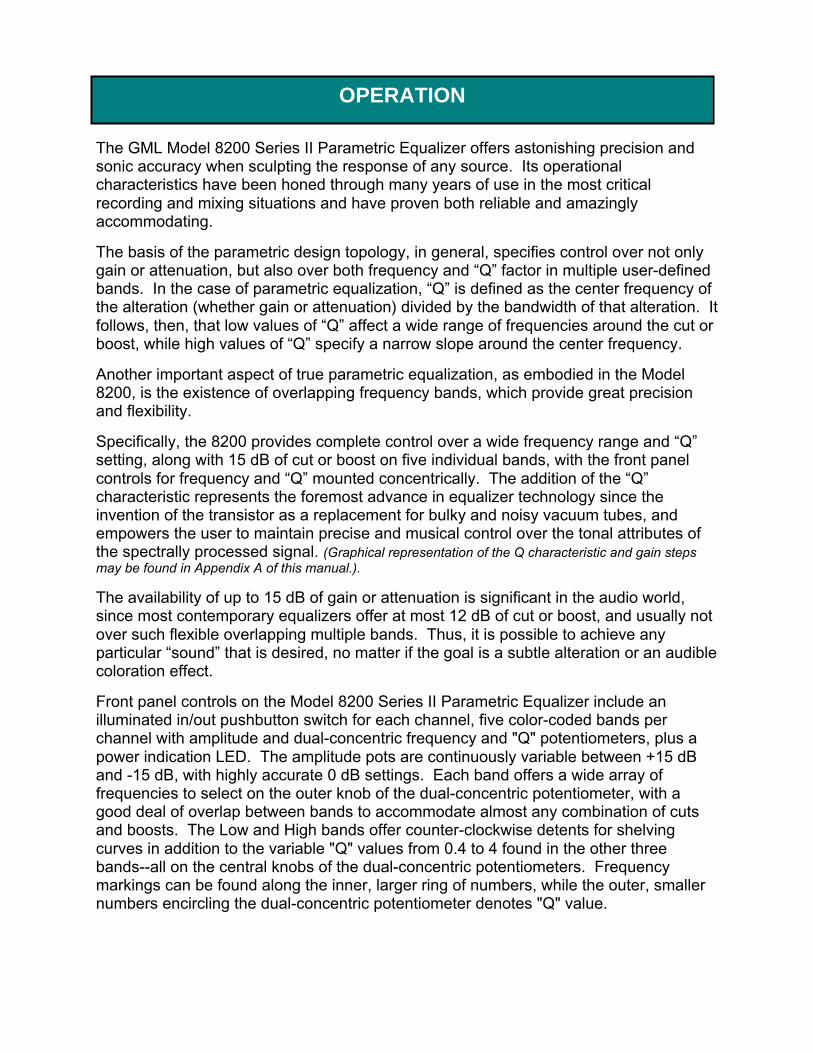
The GML Model 8200 Series II Parametric Equalizer offers astonishing precision andsonic accuracy when sculpting the response of any source. Its operationalcharacteristics have been honed through many years of use in the most criticalrecording and mixing situations and have proven both reliable and amazinglyaccommodating.
The basis of the parametric design topology, in general, specifies control over not onlygain or attenuation, but also over both frequency and “Q” factor in multiple user-definedbands. In the case of parametric equalization, “Q” is defined as the center frequency ofthe alteration (whether gain or attenuation) divided by the bandwidth of that alteration. Itfollows, then, that low values of “Q” affect a wide range of frequencies around the cut orboost, while high values of “Q” specify a narrow slope around the center frequency.
Another important aspect of true parametric equalization, as embodied in the Model8200, is the existence of overlapping frequency bands, which provide great precisionand flexibility.
Specifically, the 8200 provides complete control over a wide frequency range and “Q”setting, along with 15 dB of cut or boost on five individual bands, with the front panelcontrols for frequency and “Q” mounted concentrically. The addition of the “Q”characteristic represents the foremost advance in equalizer technology since theinvention of the transistor as a replacement for bulky and noisy vacuum tubes, andempowers the user to maintain precise and musical control over the tonal attributes ofthe spectrally processed signal. (Graphical representation of the Q characteristic and gain stepsmay be found in Appendix A of this manual.).
The availability of up to 15 dB of gain or attenuation is significant in the audio world,since most contemporary equalizers offer at most 12 dB of cut or boost, and usually notover such flexible overlapping multiple bands. Thus, it is possible to achieve anyparticular “sound” that is desired, no matter if the goal is a subtle alteration or an audiblecoloration effect.
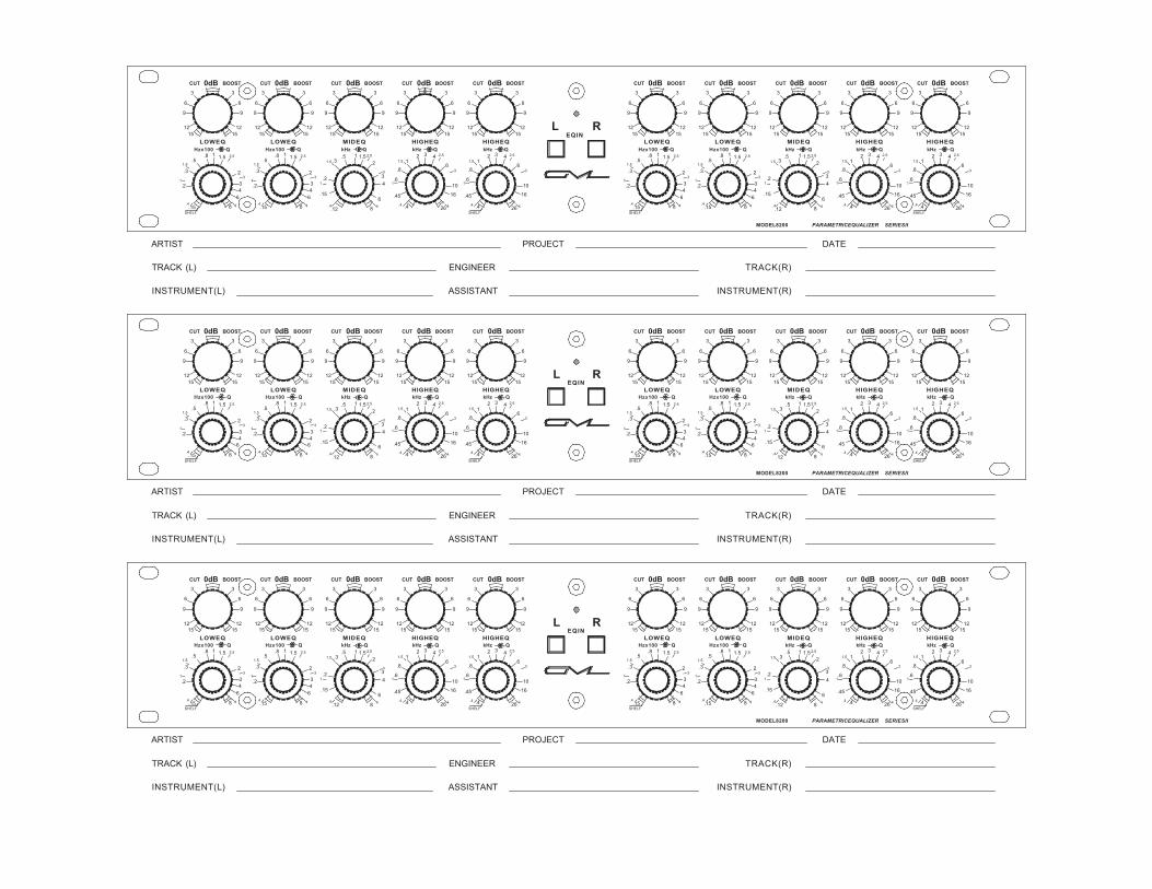
Front panel controls on the Model 8200 Series II Parametric Equalizer include anilluminated in/out pushbutton switch for each channel, five color-coded bands perchannel with amplitude and dual-concentric frequency and "Q" potentiometers, plus apower indication LED. The amplitude pots are continuously variable between +15 dBand -15 dB, with highly accurate 0 dB settings. Each band offers a wide array offrequencies to select on the outer knob of the dual-concentric potentiometer, with agood deal of overlap between bands to accommodate almost any combination of cutsand boosts. The Low and High bands offer counter-clockwise detents for shelvingcurves in addition to the variable "Q" values from 0.4 to 4 found in the other threebands--all on the central knobs of the dual-concentric potentiometers. Frequencymarkings can be found along the inner, larger ring of numbers, while the outer, smallernumbers encircling the dual-concentric potentiometer denotes "Q" value.
OPERATION
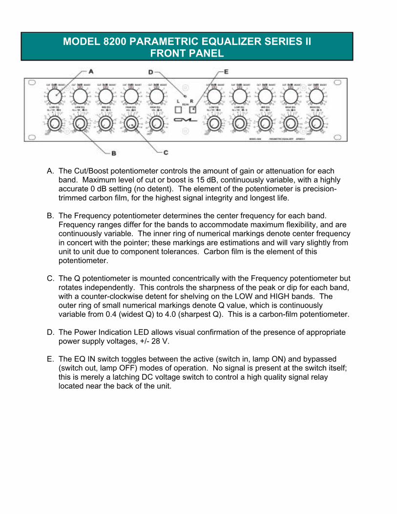
A. The Cut/Boost potentiometer controls the amount of gain or attenuation for eachband. Maximum level of cut or boost is 15 dB, continuously variable, with a highlyaccurate 0 dB setting (no detent). The element of the potentiometer is precision-trimmed carbon film, for the highest signal integrity and longest life.
B. The Frequency potentiometer determines the center frequency for each band.Frequency ranges differ for the bands to accommodate maximum flexibility, and arecontinuously variable. The inner ring of numerical markings denote center frequencyin concert with the pointer; these markings are estimations and will vary slightly fromunit to unit due to component tolerances. Carbon film is the element of thispotentiometer.
C. The Q potentiometer is mounted concentrically with the Frequency potentiometer butrotates independently. This controls the sharpness of the peak or dip for each band,with a counter-clockwise detent for shelving on the LOW and HIGH bands. Theouter ring of small numerical markings denote Q value, which is continuouslyvariable from 0.4 (widest Q) to 4.0 (sharpest Q). This is a carbon-film potentiometer.
D. The Power Indication LED allows visual confirmation of the presence of appropriatepower supply voltages, +/- 28 V.
E. The EQ IN switch toggles between the active (switch in, lamp ON) and bypassed(switch out, lamp OFF) modes of operation. No signal is present at the switch itself;this is merely a latching DC voltage switch to control a high quality signal relaylocated near the back of the unit.
MODEL 8200 PARAMETRIC EQUALIZER SERIES IIFRONT PANEL
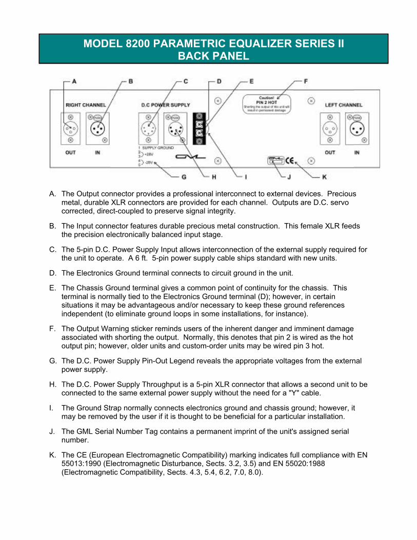
A. The Output connector provides a professional interconnect to external devices. Preciousmetal, durable XLR connectors are provided for each channel. Outputs are D.C. servocorrected, direct-coupled to preserve signal integrity.
B. The Input connector features durable precious metal construction. This female XLR feedsthe precision electronically balanced input stage.
C. The 5-pin D.C. Power Supply Input allows interconnection of the external supply required forthe unit to operate. A 6 ft. 5-pin power supply cable ships standard with new units.
D. The Electronics Ground terminal connects to circuit ground in the unit.
E. The Chassis Ground terminal gives a common point of continuity for the chassis. Thisterminal is normally tied to the Electronics Ground terminal (D); however, in certainsituations it may be advantageous and/or necessary to keep these ground referencesindependent (to eliminate ground loops in some installations, for instance).
F. The Output Warning sticker reminds users of the inherent danger and imminent damageassociated with shorting the output. Normally, this denotes that pin 2 is wired as the hotoutput pin; however, older units and custom-order units may be wired pin 3 hot.
G. The D.C. Power Supply Pin-Out Legend reveals the appropriate voltages from the externalpower supply.
H. The D.C. Power Supply Throughput is a 5-pin XLR connector that allows a second unit to beconnected to the same external power supply without the need for a "Y" cable.
I. The Ground Strap normally connects electronics ground and chassis ground; however, itmay be removed by the user if it is thought to be beneficial for a particular installation.
J. The GML Serial Number Tag contains a permanent imprint of the unit's assigned serialnumber.
K. The CE (European Electromagnetic Compatibility) marking indicates full compliance with EN55013:1990 (Electromagnetic Disturbance, Sects. 3.2, 3.5) and EN 55020:1988(Electromagnetic Compatibility, Sects. 4.3, 5.4, 6.2, 7.0, 8.0).
MODEL 8200 PARAMETRIC EQUALIZER SERIES IIBACK PANEL

Though the front panel controls seem very intuitive to the initiated and experiencedaudio engineer, the circuit design behind these controls is anything but simple andstraightforward. The GML 8200 features exemplary input and output buffering circuits inaddition to the actual equalization circuits. It is important to keep in mind that all circuitsin any device necessarily alter the sonic character of any complex signal, though thesecolorations have been meticulously minimized in the design of the 8200. Manycontemporary equalizer designs are not sensitive or wary of this aspect of audioelectronics and thus require some amount of alteration to compensate for this additionalspectral signature induced by the unit itself.
Interestingly, care has also been taken--as in all aspects of the GML 8200--to select thehighest quality components, from the potentiometers on the front panel to the smallestpassive elements. This attention to detail partially elucidates the quality found in theGML 8200 Parametric Equalizer. These component choices, coupled with superiordesign and a proclivity towards innovation, combine to make the GML 8200 ParametricEqualizer the most powerful, flexible, and transparent equalizer ever designed.
Another feature that distinguishes the GML 8200 from the myriad of other commerciallyavailable equalizers is its inherent dynamic range, which allows for the addition of 15 dBof gain in multiple frequency bands simultaneously without even a hint of distortion orloss of detail and authority. This amazing power is due in large part to the GMLpropensity to design all audio circuits from discrete components. Discrete designs,when executed properly, help to preserve not only sonic integrity and musicality, butalso to allow for the widest dynamic range through the entire signal path, thuseliminating many sonic compromises and limitations. Not only do these discretestructures--and the GML 9202 discrete opamp in particular--sound better than theirintegrated counterparts, they also offer the ability to design for higher signal levelsinternally, while also optimizing dynamic range by providing a low noise floor.
An additional benefit of the discrete circuit topology used in the GML 8200 ParametricEqualizer is increased bandwidth. Not only does this significant extension--of both highand low frequencies--provide for more detail and realism; it also ensures a greaterdegree of linearity in the traditional audio spectrum (20 Hz to 20 kHz) by locatingbandwidth poles superceding these commonly-accepted limits. Indeed, the frequencyresponse of the Model 8200 is well within +/- 0.1 dB from below 10 Hz to well above 80kHz, while the +/- 3.0 dB response exceeds the ability of most audio test apparatus tomeasure.
DESIGN
Integral to the superb quality of all GML products is the external power supply. Nopiece of electronic equipment can operate as designed without an adequate powersupply; however, most contemporary spectral processing devices do not feature asupply which can provide clean, quiet power without unduly heating the device. TheGML 8355 excels in this respect, providing clean, quiet power for the many complexand sensitive circuits of the GML 8200, while remaining cool and efficient. Internalsupply topologies are generally limited by board real-estate and thermal considerationsand thus are almost always exclusively of one or another of the switching topologies,which results in more mains-induced noise and less ability to react to highly transientsignal content or extreme circuit actions. The internal power distribution schemeemployed by the GML 8200 is also responsible--in concert with the external supplyitself--for preserving the highest audio quality throughout the many circuits of theParametric Equalizer.
It is important to keep in mind that the noise performance of the Model 8200 varies withoperational settings, with an increase in noise to be expected when switching from the'EQ Out' state to the 'EQ In' state. The reason for this characteristic is inherent to ourproprietary design, which places the control before all of the processing bands. Thisgives our parametric equalizers two distinct advantages: first, potentiometer noise isattenuated; second, the likelihood of internal overload is extremely remote, if notimpossible, even with 15 dB of gain available in each band. Interestingly, the mostdangerous condition for internal overload is experienced when using just a bit of EQwith very high-level input signals. The big difference comes not only in our designtopology, but also in our component choices. In fact, our topology is not really feasiblewith IC op-amps--they're always noisier than discretes--and only works with our quiet,transparent discrete op-amps, which can cleanly handle output signals up to +26.8 dBu.One should expect the noise floor to increase proportionally with gain, frequency, and"Q", in accordance with the laws of physics. For further information about the noisecharacteristic of the Model 8200, examine the Specifications page of this manual andthe Noise plot located in Appendix A.
POWER SUPPLY
A NOTE REGARDING NOISE
INPUT20 kΩ balanced bridging52 dB common mode rejection, averaged spot measurements 20 Hz to 20 kHz2
60 dB common mode rejection, broadband 20 Hz to 20 kHz3
+26.8 dBu maximum before clipping4
THROUGHPUT+/- 0.1 dB, 10 Hz to 80 kHz5
+/- 0.01 dB, 20 Hz to 20 kHz-3.0 dB at 260 kHz and <<10 Hz<0.001% Harmonic distortion, 20 Hz to 20 kHz, EQ Out6
0.0015% Harmonic distortion, 20 Hz to 20 kHz, EQ In0.0015% SMPTE Intermodulation distortion, 20 Hz to 20 kHz, EQ In or Out7
30 V/µsec slew rate, discrete low-noise high performance amplifiers8
noise, EQ Out: -118 dBu spot, -98 dBu broadband9
noise, EQ In: -100 dBu spot, -80 dBu broadband-132 dBu crosstalk, EQ Out10
-118 dBu crosstalk, EQ In
FORM FACTOR – 2 CHANNELS, 5 BANDS: FULLY PARAMETRIC1. 15 Hz – 800 Hz, Q of 0.4 – 4.0 or shelving, 15 dB boost/cut2. 15 Hz – 800 Hz, Q of 0.4 – 4.0, 15 dB boost/cut3. 120 Hz – 8 kHz, Q of 0.4 – 4.0, 15 dB boost/cut4. 400 Hz – 26 kHz, Q of 0.4 – 4.0, 15 dB boost/cut5. 400 Hz – 26 kHz, Q of 0.4 – 4.0 or shelving, 15 dB boost/cut
OUTPUT+26.8 dBu clipping< 3 mV output offset, stabilized by D.C. servo correction, direct couplednormally wired pin 2 hot
POWER CONSUMPTION18.2 W (650 mA at +/- 28 V D.C.), under +20 dBu signal conditionsrequires GML Model 83555-pin XLR input and throughputadditional board-level regulation, +/- 18 V D.C.
MECHANICALseparate ground and chassis connections at rearinput and output on precious metal XLR19” x 3.5” x 8.5” rack mount chassis, black anodized aluminum, silver legendweight: 6 lbs.11
SPECIFICATIONS1
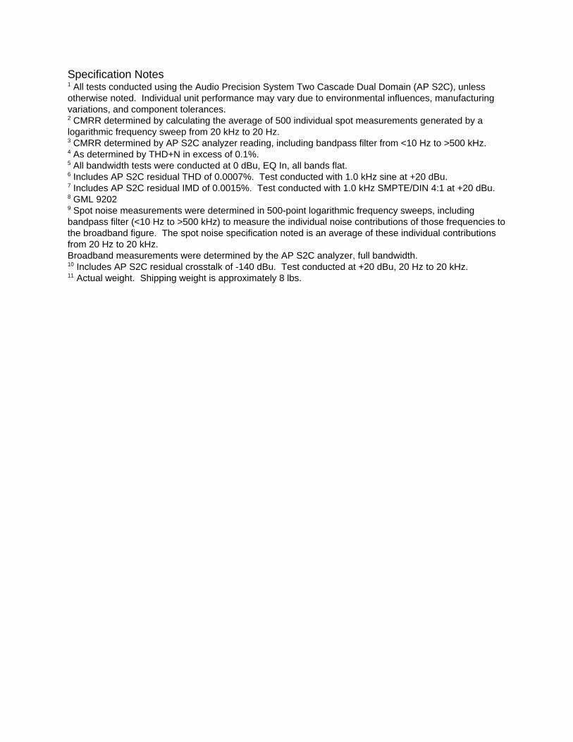
Specification Notes1 All tests conducted using the Audio Precision System Two Cascade Dual Domain (AP S2C), unlessotherwise noted. Individual unit performance may vary due to environmental influences, manufacturingvariations, and component tolerances.2 CMRR determined by calculating the average of 500 individual spot measurements generated by alogarithmic frequency sweep from 20 kHz to 20 Hz.3 CMRR determined by AP S2C analyzer reading, including bandpass filter from <10 Hz to >500 kHz.4 As determined by THD+N in excess of 0.1%.5 All bandwidth tests were conducted at 0 dBu, EQ In, all bands flat.6 Includes AP S2C residual THD of 0.0007%. Test conducted with 1.0 kHz sine at +20 dBu.7 Includes AP S2C residual IMD of 0.0015%. Test conducted with 1.0 kHz SMPTE/DIN 4:1 at +20 dBu.8 GML 92029 Spot noise measurements were determined in 500-point logarithmic frequency sweeps, includingbandpass filter (<10 Hz to >500 kHz) to measure the individual noise contributions of those frequencies tothe broadband figure. The spot noise specification noted is an average of these individual contributionsfrom 20 Hz to 20 kHz.Broadband measurements were determined by the AP S2C analyzer, full bandwidth.10 Includes AP S2C residual crosstalk of -140 dBu. Test conducted at +20 dBu, 20 Hz to 20 kHz.11 Actual weight. Shipping weight is approximately 8 lbs.
Note: This unit is a highly sensitive device that includes many complex circuits. THIS UNIT CONTAINS NO USER-SERVICEABLE PARTS.
Warning: Risk of electric shock if top cover is removed.
In the event of unit operational failure, contact the GML repair department. Refer to the"contacts" page of this manual, or for more current contact info, check our web site.Please be prepared to describe in detail the exact problem that the unit is experiencing,including: failure conditions, system signal flow, exact failure manifestation, events andactions leading to the failure, etc. Also, be able to quickly provide your contactinformation and the unit's GML Serial Number.
It is highly recommended that customers do not attempt to troubleshoot their own unitsor have them repaired at unauthorized repair centers. Opening the case of the unit willbreak several manufacturing seals and void the GML warranty--these securitymeasures cannot be readily detected nor easily thwarted, and should be respectedwholeheartedly. These measures also act to protect the intellectual property of GML sothat we may continue to design the best high-end professional analog audio peripherals.
TROUBLESHOOTING
General Information:GML, LLC.P.O. Box 1366Franklin, TN 37065615.790.1016 (ph)615.794.4802 (fax)internet:: www.massenburg.com
Repairs:GML, LLC.Attn: Repair Dept.Franklin, TN 37064615.790.1016 (ph)615.794.4802 (fax)
Engineering:GML, LLC.Attn: Jeffrey Warren, Chief EngineerFranklin, TN615.790.1016 (ph)615.794.4802 (fax)email: [email protected]
Pricing/Ordering:Frank WireThousand Oaks, CA805.492.8175 (ph)email: [email protected]
Technical Information:GML, LLC.Attn: Jeffrey or GeorgeFranklin, TN615.790.1016 (ph)615.794.4802 (fax)internet: www.massenburg.com
CONTACTS

All designs, circuit board artwork, front panel artwork, text contained herein and therein,and all other intellectual material is the sole property of George Massenburg Labs, LLC.(and/or GML, Inc.). Unauthorized use, distribution, reproduction, etc. is strictlyprohibited. GML intellectual property is protected by U.S. and international copyrightlaws. Violators will be prosecuted to the fullest extent of all applicable laws.
Transfer of ownership of this unit neither confers nor implies any transfer of ownershipof the intellectual property, proprietary design, etc. contained herein.
CreditsConcept: George Massenburg and Jeffrey Warren
Written by: Jeffrey WarrenDiagrams: Jeffrey Warren
Edited by: Jeffrey Warren and George MassenburgAdditional editing: Jenny Rosato, Frank Wire
Technical assistance: Frank Wire, Adrian Nastase, Alan Meyer
NOTICE OF COPYRIGHT AND OWNERSHIP
GML 2020 High Resolution Discrete Input Channel
GML 8300 Transformerless Microphone Preamplifier
GML 8355 Power Supply
GML 8900 Dynamic Gain Control, Series III
GML 9015 Power Supply
GML 9500 Parametric Mastering Equalizer
GML 9100 HRT Mixer
GML HRT 9145 Multi-Output Power Supply
GML 9550 Two Channel Digital Noise Filter
GML 9560 Digital Noise Filter w/ Macintosh Controller
For ordering information, contact:Frank WireThousand Oaks, CA805.492.8175 (ph)email: [email protected]
Or check our web site:www.massenburg.com
ADDITIONAL GML PERIPHERALS
4
3
2.5
1.5
1
.4.12
.15
.2
.3.5 1 1.5
2
3
4
6
8 26
16
10
6
4321
.8
.6
.45
.4 4
3
2.5
1.5
1
.426
16
10
6
4321
.8
.6
.45
.4 4
3
2.5
1.5
1
.4
SHELF
8
643
2
1.51.8.5
.3
.2
.15 4
3
2.5
1.5
1
.48
643
2
1.51.8.5
.3
.2
.15 4
3
2.5
1.5
1
.4
SHELF
3
6
9
12
3
6
9
121515
CUT BOOST0dB3
6
9
12
3
6
9
121515
CUT BOOST0dB3
6
9
12
3
6
9
121515
CUT BOOST0dB3
6
9
12
3
6
9
121515
CUT BOOST0dB3
6
9
12
3
6
9
121515
CUT BOOST0dB
Hzx100 Q kHz QHzx100 Q kHz Q kHz Q
EQINL R
LOWEQ LOWEQ MIDEQ HIGHEQ HIGHEQ
4
3
2.5
1.5
1
.4.12
.15
.2
.3.5 1 1.5
2
3
4
6
8 26
16
10
6
4321
.8
.6
.45
.4 4
3
2.5
1.5
1
.426
16
10
6
4321
.8
.6
.45
.4 4
3
2.5
1.5
1
.4
SHELF
8
643
2
1.51.8.5
.3
.2
.15 4
3
2.5
1.5
1
.48
643
2
1.51.8.5
.3
.2
.15 4
3
2.5
1.5
1
.4
SHELF
3
6
9
12
3
6
9
121515
CUT BOOST0dB3
6
9
12
3
6
9
121515
CUT BOOST0dB3
6
9
12
3
6
9
121515
CUT BOOST0dB3
6
9
12
3
6
9
121515
CUT BOOST0dB3
6
9
12
3
6
9
121515
CUT BOOST0dB
Hzx100 Q kHz QHzx100 Q kHz Q kHz Q
LOWEQ LOWEQ MIDEQ HIGHEQ HIGHEQ
MODEL8200 PARAMETRICEQUALIZER SERIESII
4
3
2.5
1.5
1
.4.12
.15
.2
.3.5 1 1.5
2
3
4
6
8 26
16
10
6
4321
.8
.6
.45
.4 4
3
2.5
1.5
1
.426
16
10
6
4321
.8
.6
.45
.4 4
3
2.5
1.5
1
.4
SHELF8
643
2
1.51.8.5
.3
.2
.15 4
3
2.5
1.5
1
.48
643
2
1.51.8.5
.3
.2
.15 4
3
2.5
1.5
1
.4
SHELF
3
6
9
12
3
6
9
121515
CUT BOOST0dB3
6
9
12
3
6
9
121515
CUT BOOST0dB3
6
9
12
3
6
9
121515
CUT BOOST0dB3
6
9
12
3
6
9
121515
CUT BOOST0dB3
6
9
12
3
6
9
121515
CUT BOOST0dB
Hzx100 Q kHz QHzx100 Q kHz Q kHz Q
EQINL R
LOWEQ LOWEQ MIDEQ HIGHEQ HIGHEQ
4
3
2.5
1.5
1
.4.12
.15
.2
.3.5 1 1.5
2
3
4
6
8 26
16
10
6
4321
.8
.6
.45
.4 4
3
2.5
1.5
1
.426
16
10
6
4321
.8
.6
.45
.4 4
3
2.5
1.5
1
.4
SHELF8
643
2
1.51.8.5
.3
.2
.15 4
3
2.5
1.5
1
.48
643
2
1.51.8.5
.3
.2
.15 4
3
2.5
1.5
1
.4
SHELF
3
6
9
12
3
6
9
121515
CUT BOOST0dB3
6
9
12
3
6
9
121515
CUT BOOST0dB3
6
9
12
3
6
9
121515
CUT BOOST0dB3
6
9
12
3
6
9
121515
CUT BOOST0dB3
6
9
12
3
6
9
121515
CUT BOOST0dB
Hzx100 Q kHz QHzx100 Q kHz Q kHz Q
LOWEQ LOWEQ MIDEQ HIGHEQ HIGHEQ
MODEL8200 PARAMETRICEQUALIZER SERIESII
4
3
2.5
1.5
1
.4.12
.15
.2
.3.5 1 1.5
2
3
4
6
8 26
16
10
6
4321
.8
.6
.45
.4 4
3
2.5
1.5
1
.426
16
10
6
4321
.8
.6
.45
.4 4
3
2.5
1.5
1
.4
SHELF
8
643
2
1.51.8.5
.3
.2
.15 4
3
2.5
1.5
1
.48
643
2
1.51.8.5
.3
.2
.15 4
3
2.5
1.5
1
.4
SHELF
3
6
9
12
3
6
9
121515
CUT BOOST0dB3
6
9
12
3
6
9
121515
CUT BOOST0dB3
6
9
12
3
6
9
121515
CUT BOOST0dB3
6
9
12
3
6
9
121515
CUT BOOST0dB3
6
9
12
3
6
9
121515
CUT BOOST0dB
Hzx100 Q kHz QHzx100 Q kHz Q kHz Q
EQINL R
LOWEQ LOWEQ MIDEQ HIGHEQ HIGHEQ
4
3
2.5
1.5
1
.4.12
.15
.2
.3.5 1 1.5
2
3
4
6
8 26
16
10
6
4321
.8
.6
.45
.4 4
3
2.5
1.5
1
.426
16
10
6
4321
.8
.6
.45
.4 4
3
2.5
1.5
1
.4
SHELF
8
643
2
1.51.8.5
.3
.2
.15 4
3
2.5
1.5
1
.48
643
2
1.51.8.5
.3
.2
.15 4
3
2.5
1.5
1
.4
SHELF
3
6
9
12
3
6
9
121515
CUT BOOST0dB3
6
9
12
3
6
9
121515
CUT BOOST0dB3
6
9
12
3
6
9
121515
CUT BOOST0dB3
6
9
12
3
6
9
121515
CUT BOOST0dB3
6
9
12
3
6
9
121515
CUT BOOST0dB
Hzx100 Q kHz QHzx100 Q kHz Q kHz QLOWEQ LOWEQ MIDEQ HIGHEQ HIGHEQ
MODEL8200 PARAMETRICEQUALIZER SERIESII
ARTIST PROJECT
TRACK (L)
INSTRUMENT(L)
TRACK(R)
INSTRUMENT(R)
ENGINEER
DATE
ASSISTANT
ARTIST PROJECT
TRACK (L)
INSTRUMENT(L)
TRACK(R)
INSTRUMENT(R)
ENGINEER
DATE
ASSISTANT
ARTIST PROJECT
TRACK (L)
INSTRUMENT(L)
TRACK(R)
INSTRUMENT(R)
ENGINEER
DATE
ASSISTANT

Note: All tests were conducted using the Audio Precision System 2 Cascade Dual Domain (APS2C). Test results are typical of Model 8200 Parametric Equalizers; however, individual unit
performance may vary due to component tolerances and environmental conditions.
1. BANDWIDTH
As can be seen in this plot, the bandwidth of the Model 8200 is quite extendedand extremely flat. Notice that the limits of the plot along the left axis are +/- 1.0dBu. The blue line represents the 'EQ Out' state, while the red line graphs the'EQ In' state. Refer to the Specifications page of the Model 8200 User's Manualfor more detailed bandwidth measurements.
2. CMRR (Common Mode Rejection Ratio, dB)
This plot depicts the relationship between CMRR level (dB, along the left axis)and frequency (Hz, along the bottom axis). In this test, a +20 dBu sine signalwas swept from 200 kHz to 10 Hz in 500 steps.
APPENDIX A:AUDIO PRECISION PLOTS
3. NOISE
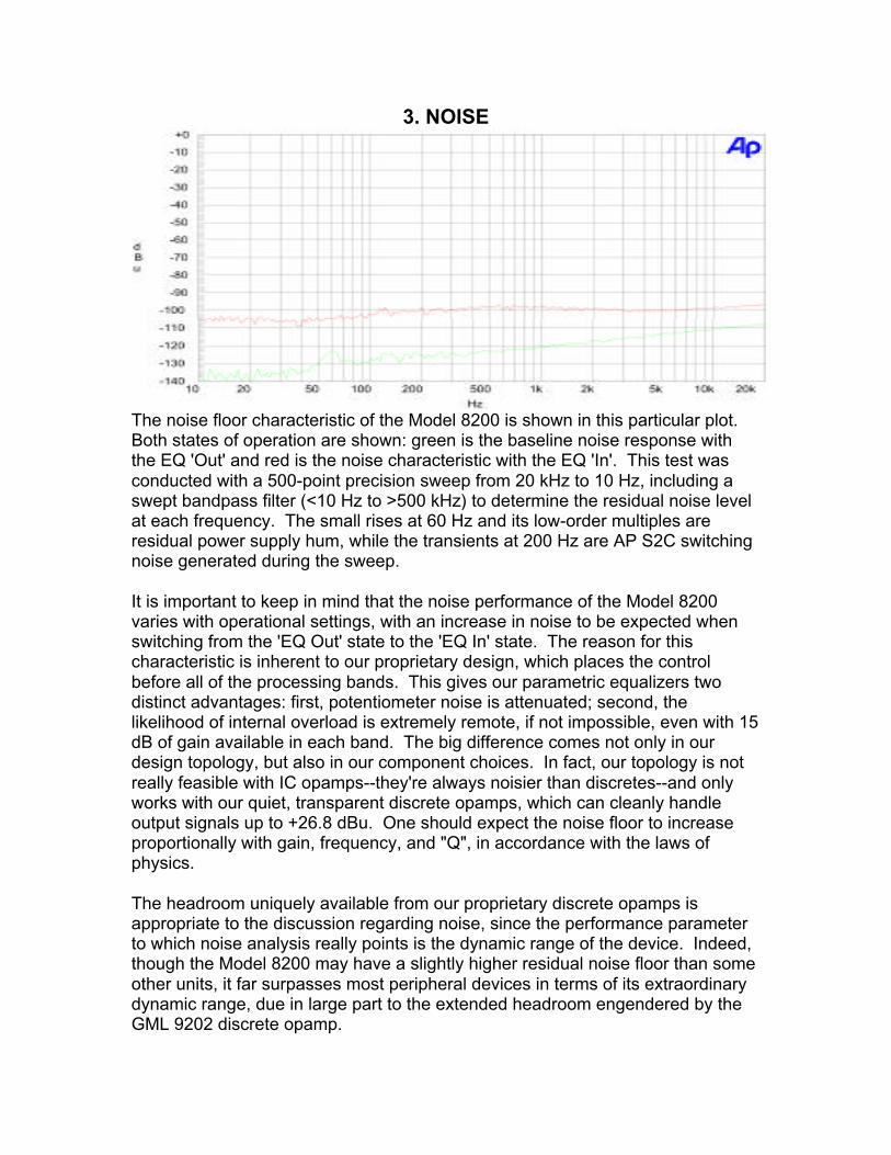
The noise floor characteristic of the Model 8200 is shown in this particular plot.Both states of operation are shown: green is the baseline noise response withthe EQ 'Out' and red is the noise characteristic with the EQ 'In'. This test wasconducted with a 500-point precision sweep from 20 kHz to 10 Hz, including aswept bandpass filter (<10 Hz to >500 kHz) to determine the residual noise levelat each frequency. The small rises at 60 Hz and its low-order multiples areresidual power supply hum, while the transients at 200 Hz are AP S2C switchingnoise generated during the sweep.
It is important to keep in mind that the noise performance of the Model 8200varies with operational settings, with an increase in noise to be expected whenswitching from the 'EQ Out' state to the 'EQ In' state. The reason for thischaracteristic is inherent to our proprietary design, which places the controlbefore all of the processing bands. This gives our parametric equalizers twodistinct advantages: first, potentiometer noise is attenuated; second, thelikelihood of internal overload is extremely remote, if not impossible, even with 15dB of gain available in each band. The big difference comes not only in ourdesign topology, but also in our component choices. In fact, our topology is notreally feasible with IC opamps--they're always noisier than discretes--and onlyworks with our quiet, transparent discrete opamps, which can cleanly handleoutput signals up to +26.8 dBu. One should expect the noise floor to increaseproportionally with gain, frequency, and "Q", in accordance with the laws ofphysics.
The headroom uniquely available from our proprietary discrete opamps isappropriate to the discussion regarding noise, since the performance parameterto which noise analysis really points is the dynamic range of the device. Indeed,though the Model 8200 may have a slightly higher residual noise floor than someother units, it far surpasses most peripheral devices in terms of its extraordinarydynamic range, due in large part to the extended headroom engendered by theGML 9202 discrete opamp.
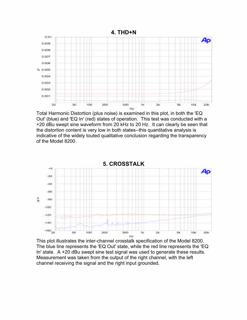
4. THD+N
Total Harmonic Distortion (plus noise) is examined in this plot, in both the 'EQOut' (blue) and 'EQ In' (red) states of operation. This test was conducted with a+20 dBu swept sine waveform from 20 kHz to 20 Hz. It can clearly be seen thatthe distortion content is very low in both states--this quantitative analysis isindicative of the widely touted qualitative conclusion regarding the transparencyof the Model 8200.
5. CROSSTALK
This plot illustrates the inter-channel crosstalk specification of the Model 8200.The blue line represents the 'EQ Out' state, while the red line represents the 'EQIn' state. A +20 dBu swept sine test signal was used to generate these results.Measurement was taken from the output of the right channel, with the leftchannel receiving the signal and the right input grounded.
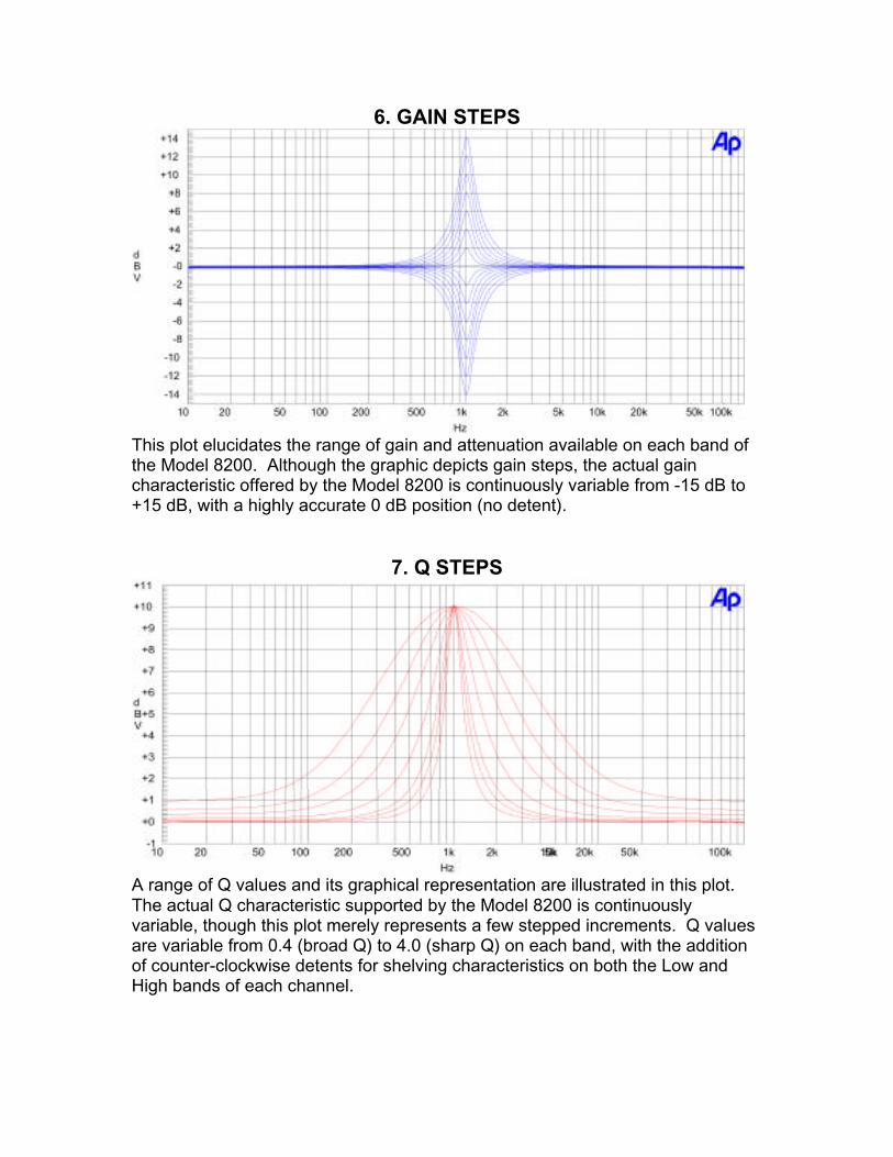
6. GAIN STEPS
This plot elucidates the range of gain and attenuation available on each band ofthe Model 8200. Although the graphic depicts gain steps, the actual gaincharacteristic offered by the Model 8200 is continuously variable from -15 dB to+15 dB, with a highly accurate 0 dB position (no detent).
7. Q STEPS
A range of Q values and its graphical representation are illustrated in this plot.The actual Q characteristic supported by the Model 8200 is continuouslyvariable, though this plot merely represents a few stepped increments. Q valuesare variable from 0.4 (broad Q) to 4.0 (sharp Q) on each band, with the additionof counter-clockwise detents for shelving characteristics on both the Low andHigh bands of each channel.
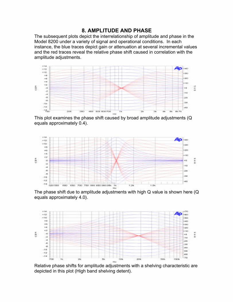
8. AMPLITUDE AND PHASEThe subsequent plots depict the interrelationship of amplitude and phase in theModel 8200 under a variety of signal and operational conditions. In eachinstance, the blue traces depict gain or attenuation at several incremental valuesand the red traces reveal the relative phase shift caused in correlation with theamplitude adjustments.
This plot examines the phase shift caused by broad amplitude adjustments (Qequals approximately 0.4).
The phase shift due to amplitude adjustments with high Q value is shown here (Qequals approximately 4.0).
Relative phase shifts for amplitude adjustments with a shelving characteristic aredepicted in this plot (High band shelving detent).