google cardboard instructions
TRANSCRIPT

For Manufacturers—
SPECIFICATIONS & TOLERANCES GUIDE

INTRODUCTION—
To help unlock virtual reality’s potential, the Cardboard viewer’s specification is open source and available for manufacturers who want to create their own viewers.
Creating your own Cardboard viewer entails five basic steps:
1. Create your viewer using product specifications2. Test your viewer3. Create a viewer profile and generate a QR code4. Design your QR code and place it on your viewer5. Get your viewer “Works with Google Cardboard” certified
You can find comprehensive details about each of these steps in Google’s online Cardboard for Manufacturers Help Center.
HOW TO USE THIS GUIDE—
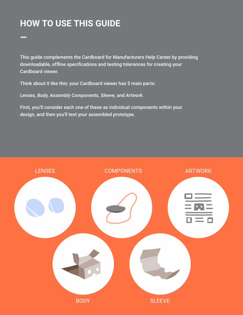
This guide complements the Cardboard for Manufacturers Help Center by providing downloadable, offline specifications and testing tolerances for creating your Cardboard viewer.
Think about it like this: your Cardboard viewer has 5 main parts:
Lenses, Body, Assembly Components, Sleeve, and Artwork.
First, you’ll consider each one of these as individual components within your design, and then you’ll test your assembled prototype.
COMPONENTS
SLEEVE
ARTWORKLENSES
BODY

ENVIRONMENTAL CONDITIONS—
All components in your Google Cardboard viewer must be rated for the following storage conditions that may occur during shipment in cargo planes, sea shipping containers, etc.
Parameters Minimum Maximum Unit
Temperature -30 50 °C

LENSES—
SPECIFICATIONS—
Cardboard lenses enable viewer users to focus their vision on the smartphone screen and allows the smartphone to be placed at short focal distances (2-5 cm). They are critical to providing a great VR experience for users.
Parameters Value Unit Notes
Designed FOV 80 ° Circular total field of view
Nyquist frequency 8.7 lp/mm
Based on Nexus 5 screen resolution (1920 x 1080 px), pixel pitch 57.6 μm
Display cover glass thickness 1.4 mm nd =1.5, v = 55
Design wavelength 550 nm +/- 25 nm (equal weighting)
Pupil diameter 15 mm Also known as the “eyebox”
Eye relief 18 mm From the designed eye pupil to lens surface vertex
Nominal virtual image dis-tance -667 mm None
Lens diameter 34 mm None
Lens edge thickness 1.5 mm At 34 mm diameter
Lens material PMMA n/a nd =1.492, v = 57.4
Tab to screen distance 39.07 mm From the tab surface (facing display) to the front surface of display coverglass

TESTING—
Modulation transfer function
Tolerances
Modulation transfer function (MTF) measures a lens’ optical performance potential. Use the MTF specifications for nominal operations conditions below when designing your Cardboard lens.
Inspect your first article lenses to verify that tolerances are respected. Then, perform visual lens quality checks for any surface distortions, blurry areas, blemishes, etc.
Parameters Value Unit
Min on-axis MTF @ Nyquist Frequency, with evaluation pupil centered 80 %
Min MTF @ Nyquist Frequency within +/-25° FOV with 4 mm diameter evaluation pupil 8.7 %
Inspection item Tolerance Unit
Center thickness 8.794 +/- 0.1 mm
Lens diameter including tabs 40.0 +/- 0.1 mm
Lens diameter without tabs 34.0 +/- 0.1 mm
Lens tab thickness 1.65 +/- 0.1 mm
R1 surface form (figure error) < 10 µm
R2 surface form (figure error) < 10 µm
R1 surface roughness (angstroms RMS) < 0.05 µm
R2 surface roughness (angstroms RMS) < 0.05 µm
Lens material PMMA n/a

Inspection item Tolerance Unit
Surface decenter < 20 µm
Surface tilt < 20 arcmin
Surface quality (scratch/dig) 160 / 50
Visual verification
Common lens surface problems arise from manufacturing process issues like incorrect cooling/cycle times can be detected by “sliding” the lens over a high-contrast straight line and visually inspecting for any distortions. You should see a straight line, not a wavy one. Below are two examples of good and bad lenses.
Good lens (straight image) Bad lens (wavy image)
BODY—
SPECIFICATIONS—
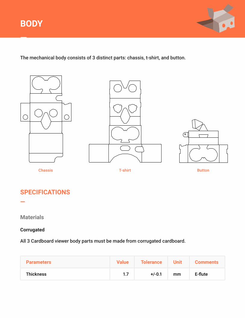
The mechanical body consists of 3 distinct parts: chassis, t-shirt, and button.
Parameters Value Tolerance Unit Comments
Thickness 1.7 +/-0.1 mm E-flute
Chassis T-shirt Button
Materials
Corrugated
All 3 Cardboard viewer body parts must be made from corrugated cardboard.
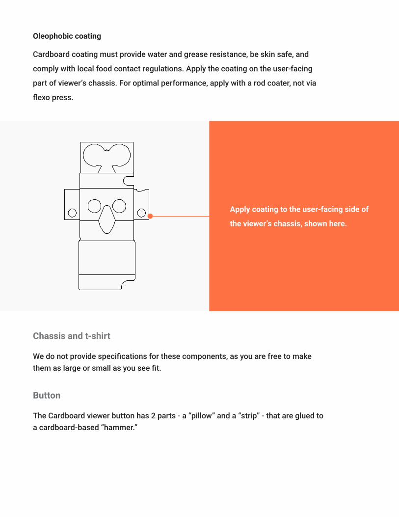
Oleophobic coating
Cardboard coating must provide water and grease resistance, be skin safe, and
comply with local food contact regulations. Apply the coating on the user-facing
part of viewer’s chassis. For optimal performance, apply with a rod coater, not via
flexo press.
Apply coating to the user-facing side of
the viewer’s chassis, shown here.
Chassis and t-shirt
Button
We do not provide specifications for these components, as you are free to make them as large or small as you see fit.
The Cardboard viewer button has 2 parts - a “pillow” and a “strip” - that are glued to a cardboard-based “hammer.”

Conducive strip
Conducive pillow
Cardboard button parts: pillow (1), hammer (2), and conductive strip (3).
Parameters Value Unit
Material Metallized fabric (polyester Ni/Cu) n/a
Surface resistivity < 0.03 Ω/sq.
Z-axis resistance < 0.03 Ω
Parameters Value Unit
Surface material Metallized fabric (polyester Ni/Cu)
Core material Soft urethane foam
Core surface resistivity < 0.07 Ω/sq.
PSA type Conductive
PSA Z-axis resistance < 0.05 Ω

Parameters Value Unit Diagram detail
Distance between two fold lines defining the thickness of Cardboard chassis 40 (+/-0.5) mm A, C
Distance between the centers of lens holders (IPD) 64 (+/-0.5) mm B
TESTING—
Corrudate tooling
Verify the critical dimensions for the corrugate tooling (e.g. die-cuts) before proceeding to production.
From left to right. Critical “A” and “B” dimensions on the Cardboard “t-shirt” part. Critical “C” dimension on the Cardboard “chassis” part.

Parameters Value
Material Woven nylon
PSA type Acrylic-based adhesive
Acrylic-based adhesive Black
VELCRO—A Google Cardboard viewer has two round hook-and-loop velcros to assemble the side flaps, and an oval hook and-loop velcro to assemble the top flap.
ASSEMBLY COMPONENTS—
Oval velcro
Hook-and-loop velcros as used in Google Cardboard: (1) oval “loop” velcro (2) oval “hook” velcro (3) round “loop” velcro (4) round “hook” velcro
Parameters Value Tolerance Unit
Material Woven nylon
Diameter 19.25 +/- 0.25 mm
PSA type Acrylic-based adhesive
Color Black
RUBBER BAND—
Round velcro
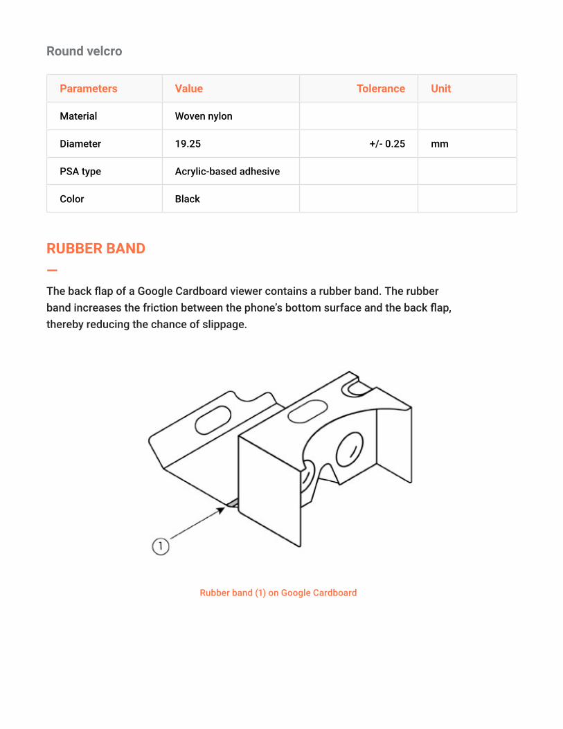
The back flap of a Google Cardboard viewer contains a rubber band. The rubber band increases the friction between the phone’s bottom surface and the back flap, thereby reducing the chance of slippage.
Rubber band (1) on Google Cardboard
Parameters Value Unit
Dimensions 76.2 x 6.35 x 1 mm
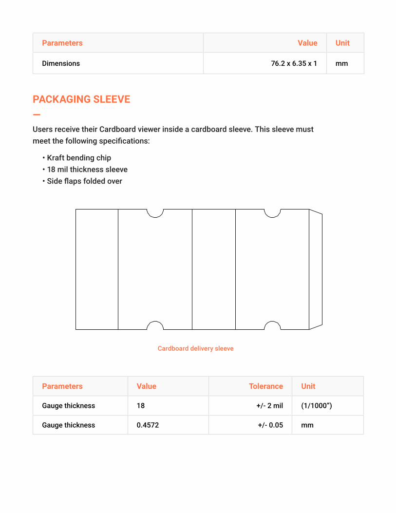
PACKAGING SLEEVE—Users receive their Cardboard viewer inside a cardboard sleeve. This sleeve must meet the following specifications:
• Kraft bending chip • 18 mil thickness sleeve • Side flaps folded over
Cardboard delivery sleeve
Parameters Value Tolerance Unit
Gauge thickness 18 +/- 2 mil (1/1000”)
Gauge thickness 0.4572 +/- 0.05 mm

Parameters Value Tolerance Unit
Paper density 337 +/- 10 g/m2
Material Kraft bending chip

Your Cardboard viewer must include a QR viewer profile on the chassis bottom. You may also optionally include an isometric viewer diagram and isometric assembly instructions.
ARTWORK—
An isometric viewer diagram on the sleeve (left); the assembly instructions on the chassis (center); QR viewer profile (right, required).
QR VIEWER PROFILE—Users configure their smartphones for Cardboard by scanning the QR viewer profile on their Cardboard viewer. This profile encodes the viewer parameters and ensures that all apps written using the Cardboard SDKs work well on that viewer. Click to learn more about QR viewer profiles. Also, be sure to:
• Include the QR viewer profile on the viewer itself • Include the QR viewer profile on the viewer’s packaging and / or on its website

Parameters Value Unit
Primary button type Indirect touch
Screen to lens distance 39.3 mm
Inter-lens distance 63.9 mm
Screen vertical alignment Bottom
Tray to lens-center distance 35 mm
k1 distortion coefficient 0.33582564
k2 distortion coefficient 0.55348791
Viewer profile and badge guidelines
Size
When used in digital media, the QR profile size should never be smaller than 74 x 74 px (in other words, the individual QR modules should never be smaller than 2 x 2 px.) When used in print, the QR profile size should never be smaller than 0.6 x 0.6” / 15 x 15 mm. Do not increase the size of a QR profile to the point where it would become a dominant graphical element in your design.

Multiple QR codes
QR codes are difficult to scan when multiple codes are placed closely next to each other. If your viewer, packaging, website or other materials include multiple QR codes, ensure thatthese QR codes are spaced sufficiently far apart.For example, at 7” / 175 mm scanning distance, a typical smartphone QR reader covers about 5.5 x 8” / 140 x 200 mm area. Do not place any other QR codes in this area.
Do
• Use only two colors (e.g. white and orange, instead of white and black). • Preserve the color contrast on dark backgrounds by reversing-out the print process. Ultimately, pixels which were black in the original QR code should remain darker than the pixels which were originally white:
Placement on your viewer
To avoid visual clutter, the clear space around the viewer profile should be equal to or greater than the QR code position patterns ( ). Do not place photos, text or any other graphic elements inside the minimum clear space.
Color options
You can adapt the colors of the QR code to match the design of your viewer. There are a few things to bear in mind when using different color schemes with your QR code.

Make sure to leave a border around the position patterns ( ) as per images above if you are using reversed-out QR profiles. Alternatively, you can include a one-module width border around the whole reversed-out QR profile:
Don’t
• Use more than two colors:
• Decrease the contrast between the foreground and the background:

• Invert the color contrast such that the pixels which were originally black end up being brighter than the originally white pixels:
• Place the profile on a busy or non-uniform background:
• Use a different color for the border:
Other QR code modifications
Avoid modifying the generated QR viewer profile in any way, apart from scaling/color changes.
Don’t
• Change the shape of QR modules:

• Add or modify the existing visual elements:
• Add shadows:
• Disproportionately stretch or skew the QR profile:
Optional elements
Viewer diagram
Some manufacturer include an isometric diagram of the completely assembled viewer on the packaging sleeve. A diagram of the completed viewer is optional.
Assembly instructions
You may also choose to include an isometric image of the assembly instructions. Typically, manufacturers include these on the back flap of the chassis. Assembly instructions are optional.

The “Works with Google Cardboard” (WWGC) badge and term are designed to indicate that a particular VR viewer has been certified by the manufacturer to be compatible with a Google Cardboard application ecosystem.
You may use the Google Cardboard assets described below (specifically the “Works with Google Cardboard” badge and the phrase “Works with Google Cardboard”) in plain text, on your viewer, on your viewer’s packaging and on your promotional and advertising materials if and only if you have been accepted to the WWGC Program and received a written approval from Google.
‘WORKS WITH CARDBOARD” BADGE & TERM—
BADGE COLORS—Primary
Orange is the primary WWGC badge color. Use it whenever possible.
Secondary
If you cannot use the primary badge because of an existing color scheme, use the secondary badge (gray). If the surrounding background requires a higher contrast, you can also use a reversed-out version of the gray badge. No other color variations are permitted.

TRANSPARENCY—
MINIMUM SIZE—
CLEAR SPACE—
You can also make the reversed-out badge transparent to match your viewer’s color scheme:
The badge width should never be smaller than 64 px when used in digital media, and 0.5” when printed.
Minimum clear space around the WWGC badge is equal to one sixth of the badge’s width. Do not place photos, text or any other graphic elements inside the minimum clear space.

MODIFICATIONS—Avoid modifying the WWGC badge in any way, apart from scaling and using the appropriate color options as described above. Additionally:
• Do not use color badges other than orange or gray:
• Do not use more than two colors:
• Do not add reflections or shadows:
• Do not scale the badge disproportionately, or skew it:

• Do not add any visual elements or modify the existing ones:
Do not make the WWGC badge a dominant graphic in a printed or digital layout. In particular, the WWGC badge should occupy less area than your viewer or company signage.
If your viewer supports multiple platforms, the WWGC badge should be placed first in the lineup of badges, and should be of equal or greater size.
If you are placing the WWGC badge on your website, make sure that the badge links to http://g.co/cardboard.
If your viewer has been accepted to the WWGC Program and you have received a written approval from Google, you can use any of the following text with your viewer messaging: “This [device] works with Google Cardboard.” Or, “Works with Google Cardboard.” Do not modify these phrases and change the conjugation. For example, do not say “Working with Google Cardboard,” or “[device] works on Google Cardboard”. Use the title case for “Works with Google Cardboard”, unless the phrase is used within a sentence (“we would like to announce that [device] now works with Google Cardboard”). With any of the above text, you must also include the following attribution statement on your website(s) or printed materials: “Google Cardboard is a trademark of Google Inc.”.
BADGE PLACEMENT—
MULTIPLE BADGE USE—
WEBSITE USE—
“WORKS WITH CARDBOARD” TERM USE—
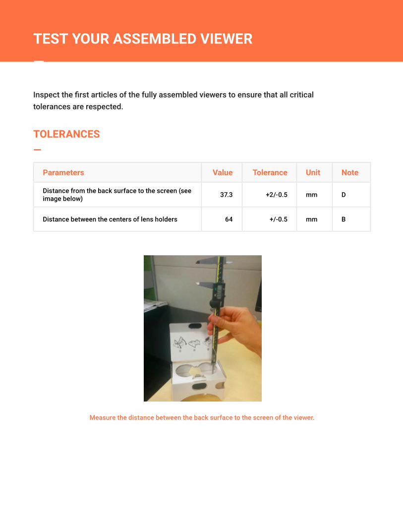
Inspect the first articles of the fully assembled viewers to ensure that all critical tolerances are respected.
TEST YOUR ASSEMBLED VIEWER—
TOLERANCES—
Parameters Value Tolerance Unit Note
Distance from the back surface to the screen (see image below) 37.3 +2/-0.5 mm D
Distance between the centers of lens holders 64 +/-0.5 mm B
Measure the distance between the back surface to the screen of the viewer.
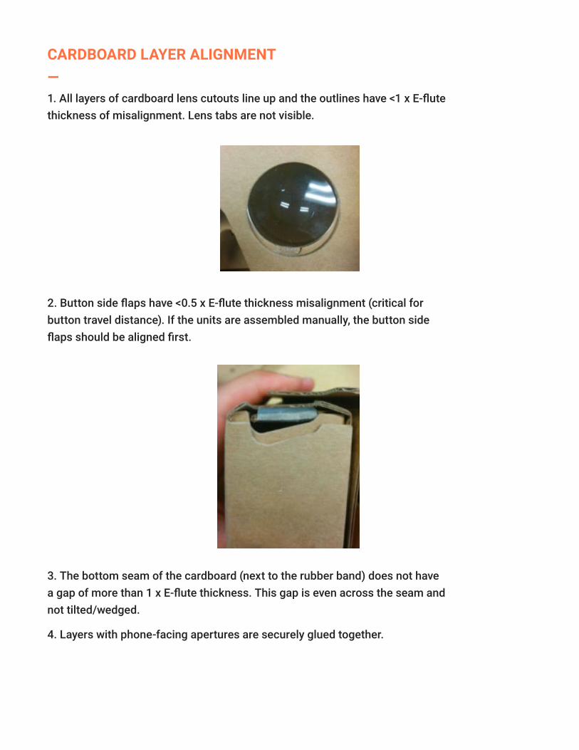
CARDBOARD LAYER ALIGNMENT—1. All layers of cardboard lens cutouts line up and the outlines have <1 x E-flute thickness of misalignment. Lens tabs are not visible.
2. Button side flaps have <0.5 x E-flute thickness misalignment (critical for button travel distance). If the units are assembled manually, the button side flaps should be aligned first.
3. The bottom seam of the cardboard (next to the rubber band) does not have a gap of more than 1 x E-flute thickness. This gap is even across the seam and not tilted/wedged.
4. Layers with phone-facing apertures are securely glued together.

BUTTON FUNCTIONALITY—
VELCRO ALIGNMENT—
1. Parts of the “hammer” do not come unglued after repeated presses TIP: Ungluing can occur during assembly when glue dries before components are pressed together, or from not applying sufficient amounts of glue.
2. The button is easily pushed down. Upon release, it springs back.
3. The conductive pillow is centered within the phone-facing apertures, and the bottom edge of the conductive pillow aligns with the corresponding cardboard edge.
1. Upon closing and re-opening the velcros, the PSA does not peel.
2. All 6 velcro pieces are present and >95% aligned. The following example does not meet alignment criteria.

ADDITIONAL QUALITY CHECKS—1. No glue or tape show around the cardboard edges.
2. The viewer does not have false scores.
3. The lenses are free of contamination, such as glue, velcro loop/hook pieces, cardboard chips or other debris.
