gophone - a software product line in the mobile phone domain
TRANSCRIPT

A publication by Fraunhofer IESE
GoPhone - A Software Product Line in the Mobile Phone Domain
Authors:Dirk MuthigIsabel JohnMichalis Anastasopoulos Thomas ForsterJörg DörrKlaus Schmid
IESE-Report No. 025.04/EVersion 1.0March 5, 2004
Fraunhofer InstitutExperimentelles
IESE
Software Engineering


GoPhone - A Software Product Line in the Mobile Phone Domain
Autoren:Dirk MuthigIsabel JohnMichalis Anastasopoulos Thomas ForsterJörg DörrKlaus Schmid
Report ViSEK/016/EVersion 1.005.03.2004Klassifikation: public


vCopyright ViSEK 2004
Zusammenfassung
This report provides insights into component-based product line engineering on the basis of a case study from the mobile phones domain. The reader follows the systematic creation of a hypothetical software product line according to the PuLSETM and KobrA methods developed at Fraunhofer IESE. Scoping as well as Application and Framework Engineering are covered. Our goal was to provide as broad an overview as possible. For that reason many details haven been inten-tionally left out.
Schlagworte: Software Product Lines, Component-oriented development, Scoping, Domain Analysis, Architecting, Implementation, Decision Modelling, Instantiation, Appli-cation Engineering, Framework Engineering
Das diesem Bericht zugrundeliegende Vorhaben wurde mit Mitteln des Bundesministeriums für Bildung und Forschung unter dem Förderkennzeichen 01 IS A02 gefördert.Die Verantwortung für den Inhalt dieser Veröffentlichung liegt bei den Autoren.

vi Copyright ViSEK 2004
viiCopyright ViSEK 2004
Inhaltsverzeichnis
1 Introduction 11.1 Motivation 11.2 Software Product Lines 21.3 PuLSE (Product Line Software Engineering) 41.3.1 Deployment Phases 51.3.2 Technical Components 61.3.3 Support Components 81.4 The KobrA Method 91.4.1 Framework Engineering 101.4.2 Application Engineering 141.5 The Go Phone Case Study 171.6 Outline 18
2 Product Line Scoping 202.1 Understanding the Product Portfolio 222.2 Describing the product portfolio 232.2.1 Go Phone Smart 262.2.2 Go Phone XS 272.2.3 Product Genealogy and Characterization 282.3 Describing the relevant domains 322.3.1 Messaging 332.3.2 Message Controller 362.3.3 Domain Structure 392.3.4 Initial Product Map 392.4 Analyzing benefits and risks of domains 42
3 Domain Analysis 493.1 Customization of PuLSE CDA 503.2 Use Case Modelling 523.2.1 Use Case Send Message 563.2.2 Use Case Show Message 583.2.3 Use Case Start Chat 623.2.4 Use Case View and Save calendar entry 653.3 Feature Modelling 663.4 Decision Modelling 72
4 Product Line Architecture 744.1 Architectural Styles & Patterns 744.1.1 Mediator Pattern 744.1.2 State pattern 75

viii Copyright ViSEK 2004
4.2 The KobrA process 764.2.1 Context Realization 764.2.2 PhoneComponent 784.2.3 ComponentManager 804.2.4 Component Tree 814.2.5 Implementation models 824.3 Variability Mechanisms 834.3.1 Aspect oriented programming 85
5 Infrastructure Usage 885.1 Product Derivation Process 885.2 Domain Model Instantiation 885.3 Process Hierarchy Instantiation 925.4 Architecture Instantiation 935.5 Code Generation 945.5.1 Increasing the efficiency of Component implementation 945.5.2 Graphical Modelling of a Phone Component 955.5.3 Supporting Variability 955.5.4 The technical realization 965.5.5 Conclusion 99
6 Analysis and Future Work 100
7 Glossary 101
8 References 102

1
Introduction
Copyright ViSEK 2004
1 Introduction
This report describes a case study in developing and documenting software product lines, which has been performed in the context of the ViSEK project.
This chapter introduces the context and the background of the case study. It begins with the overall motivation for performing it, then it introduces the gen-eral concepts of software product lines, as well as describes the methods and techniques used, that is, PuLSE (Product Line Software Engineering) and the KobrA method.
Section 1.5 and Section 1.6 finally give a high-level overview of the case study described and respectively of the outline of the overall report.
1.1 Motivation
Software development today faces several challenges. There is a critical need to reduce cost, effort, and time-to-market of software products, but, at the same time, complexity and size of products are rapidly increasing and customers are requesting more and more quality products tailored to their individual needs [10].
Experience of many software organizations shows that the traditional way of software development is not efficient enough to meet all these challenges. Here, traditional software development means that all development activities are performed in the context of a development project and thus focus only on the particular software ultimately delivered by a single project. Hence, an approach is needed that provides a point-of-view orthogonal to the project structure and thus allows commonalities among projects to be identified and effort to be shared between several projects.
Software product line engineering is such an approach that views the software products delivered by an organization as members of the same product family, which share several common characteristics. Although significant effort has been invested into research and transfer of product line concepts, theory, and methods in academia, as well as in industry ([11], [12], [13]) it is still a challenge for organizations to identify the methods and techniques applicable in their par-ticular context and to seamlessly integrate them with their current practices, tools, and standards.

2
Introduction
Copyright ViSEK 2004
This also results from the fact that product line methods are typically described and published in a very abstract way simply because the concrete examples are too valuable to an organization to be made publicly available.
The case study described in this report thus serves two purposes. On the one hand, it is directly meant to be a “complete” example of a software product line that can be studied by researchers and practitioners to support their under-standing of what software product lines practically are. On the other hand, we hope that the case study provides the material that more people developing and describing product line technologies can use to demonstrate and illustrate their methods, techniques, or tools. If this would be achieved, researcher and practi-tioners could both better compare the different approaches available.
1.2 Software Product Lines
Nearly all software organizations today develop and maintain more than a single product. This holds for organizations that develop tailored systems individually for single customers, as well as for organizations that develop products for a mass market. Even for organizations that believe to develop a single product only, surveys have uncovered that also these organizations spend most of their resources on tailoring their systems to the needs of individual customers or enhancing systems by features that are newly required by customers [14], and thus also these organizations must maintain and evolve a set of customer-spe-cific variants.
The products developed by an organization typically are similar applications in the same application domain. Hence, these products share some common char-acteristics and thus can be viewed as a software product line. Product lines of organizations can generally be characterized by the rate of variety and change over time, that is the number of product variants existing at a given point in time and the difference between the sets of existing product variants between a fixed time span. The main product-line categories are visualized in Figure 1.
Figure 1:Character-ization scheme for software product lines
Variety
Change Rate
Variety-Intensive
Change-Intensive
Dynamic
Variety
Change Rate
Variety-Intensive
Change-Intensive
Dynamic
3
Introduction
Copyright ViSEK 2004
Today, complexity and size of software products is rapidly increasing and cus-tomers are requesting more and more quality products tailored to their individ-ual needs. Consequently, the variety and the change rate of the average prod-uct line increase. The higher the variety or the change rate of its product line, the bigger the challenges an organization must master and thus the higher the requirements on its development skills. Hence, there is a need for organizations to learn how to manage a product line or how to improve their way of manag-ing it.
The following list gives an overview of typical problems that arise as the com-plexity of a product line increases:
• The same functionality is developed several times for different products or customers.
• The same changes must be repeated for different products.• Identical features behave differently depending on the particular product.• Some products cannot be updated anymore and customers must migrate to
another product variant or version.• It is not possible to predict the costs of introducing an implemented feature
from a product into another variant.• Changes to the common infrastructure lead to unpredictable changes of
behavior in the various products.• The maintenance effort explodes and thus free resources for new product
developments become rare.
Product line engineering is an approach whose goal is to avoid these kind of problems by explicitly managing software product lines. Therefore, the overall development life-cycle is split into two concurrent phases: family engineering and application engineering (as depicted in Figure 2). Family engineering ana-lyzes current and planned products developed by an organization with respect to their common and varying characteristics (i.e. commonalities and variabilities). The commonalities and variabilities are then used to construct a product line infrastructure, which is a repository of reusable artifacts. Application engineer-ing uses this infrastructure to construct particular products

4
Introduction
Copyright ViSEK 2004
Figure 2:Product line engineering life-cycle
.
However, the above problems may also exist in organizations that already recog-nized their product line and thus created a product line infrastructure (or a com-mon platform) for their systems. This happens simply because either developers of particular products do not know that the functionality they require has already been realized as part of the platform (or in the context of another project) or the platform does not evolve as fast as required and thus provides over time less and less of the functionality required. Hence, the usage and evolu-tion of the product line infrastructure must be supported in a way that avoids these problems. Therefore, product line technologies are required that effec-tively support the identification of reusable artifacts, as well as the efficient adaptation and extension of the infrastructure. The latter requires explicit means for capturing and controlling commonalities and variabilities.
This report describes a case study that demonstrate how a software product line can be realized successfully in practice. The case study applies two methods for systematically developing software product lines: PuLSE and the KobrA method. These are described in the following two subsections.
1.3 PuLSE (Product Line Software Engineering)
PuLSE is a method for enabling the conception and deployment of software product lines within a large variety of enterprise contexts. This is achieved via a product-centric focus throughout its phases, customizability of its components, an incremental introduction capability, a maturity scale for structured evolution, and adaptations to a few main product development situations.
Figure 3 shows an overview of PuLSE.
Software Development Organization
Domain
Family Engineering
Application Engineering
Product LineInfrastructure
(Domain Artifact Base)
Feedback
Requirements CRequirements B
Product Requirements A
ProductProduct
Requirements
Software Development Organization
Domain
Family Engineering
Application Engineering
Product LineInfrastructure
(Domain Artifact Base)
Feedback
Requirements CRequirements B
Product Requirements A
ProductProduct
Requirements

5
Introduction
Copyright ViSEK 2004
Figure 3:PuLSE over-view
.
PuLSE is centered around three main elements: the deployment phases, the technical components, and the support components.
1.3.1 Deployment Phases
The deployment phases are logical stages of the product line life cycle. They describe activities performed to set up, use, and evolve product lines. The deployment phases are:
PuLSE initialization
PuLSE is customized to the context of its application. The principle dimensions of adaptation are the nature of the domain, the project structure, the organiza-tional context, and the reuse aims.
The initialization phase is realized by the technical component for customizing, PuLSE-BC.
Product line infrastructure construction
The product line infrastructure is set up. This is done by scoping, modelling, and architecting the product line.
These activities are realized by the corresponding technical components PuLSE-Eco, PuLSE-CDA, and PuLSE-DSSA, respectively.
Customizing (BC)
Product LineInfrastructure
Evolution
PuLSE Initialization
Product LineInfrastructureConstruction
Product LineInfrastructure Usage
Scoping (Eco)
Modelling (CDA)
Architecting (DSSA)
Evolving & Mgmt. (EM)
Project Entry Points Maturity Scale Organization Issues
Support Components
Deployment Phases Technical Components
Instantiating (I)

6
Introduction
Copyright ViSEK 2004
Product line infrastructure usage
The product line infrastructure is used to create a single product line member. This is done by instantiating the product line model and architecture.
The PuLSE-I technical component realizes this phase.
Product line infrastructure evolution
Concepts within the domain or other requirements on the product line may change over time. The evolution of the product line is handled in this phase.The process for controlling evolution is realized by the PuLSE-EM technical com-ponent.
1.3.2 Technical Components
The technical components provide the technical know-how needed to opera-tionalize the product line development. They are used throughout the deploy-ment phases. The technical components are:
Baselining and Customization (PuLSE-BC)
Baseline the enterprise and customize PuLSE. The result is an instance of PuLSE — that is, instances of the other technical components — tailored to the specific application context.
Economic scoping (PuLSE-Eco [3])
Identify, describe, and bound the product line. This is done by determining the characteristics of the products that constitute the product line. Economic scop-ing in PuLSE means that the scope is determined with respect to business objec-tives and planned products.
The output of PuLSE-Eco are the product characteristic information and the scope definition. These outputs together describe the contents of the product line. The product characteristic information describes the common and variable characteristics of all products in the product line.The scope definition identifies the range of characteristics that systems in the product line should cover. The basis for the scope definition is a product map that relates the characteristics to the different products. A product map is a table, which lists the characteristics mentioned in the product characteristic information as its rows and the products as its columns. The table cells contain a cross when a product contains a characteristic.
7
Introduction
Copyright ViSEK 2004
To determine the scope, the benefit provided by including a characteristic into the scope relative to business objectives is determined. The scope definition is then an identification of a subset of the characteristics that shall be developed for reuse.
The benefit is calculated with functions. Characterization functions describe the benefit of having a certain characteristic in a certain product. The business objectives are expressed in terms of benefit functions that describe the benefit accrued by integrating a certain characteristic into the product line scope. By gathering values for the characterization functions, the benefit functions can be solved to determine the appropriate scope.
Customizable Domain Analysis (PuLSE-CDA [4])
Elicit the requirements for a domain and document them in a domain model (a.k.a. product line model).
A product line model is composed of multiple workproducts that capture differ-ent views of a domain. Each view focuses on particular information types and relations among them. In the workproducts, common requirements (commonal-ities) and requirements that vary for the different systems (variabilities) are mod-eled. Therefore, they are referred to as generic workproducts. There are three types of variabilities: optional, alternative, and range requirements.
Each generic workproduct has defined meta elements for each variability type. Meta elements indicate points of variation and enable the instantiation of the workproducts.
The variabilities (expressed by meta elements) are connected to decisions that, when completely resolved, specify a particular system, a member of the product line. The decisions are at different levels of abstraction and are hierarchically structured based on constraints among them. The decision hierarchy is called the domain.
To specify a particular system in the product line, the product line model is com-pletely instantiated. The instance of the product line model is generated by pass-ing all resolutions of the decisions to the connected meta elements, which instantiate their corresponding part of the product line model.
Domain Specific Software Architecture development (PuLSE-DSSA [5])
Develop a reference (or domain specific) architecture based on the product line model.
A reference architecture description consists of multiple models that describe different views on the reference architecture. Each of the views is composed of
8
Introduction
Copyright ViSEK 2004
view-specific components and connectors that describe the architecture from a different perspective. Similar to a product line model, a reference architecture description is an architecture description that also captures variability in the architectures for the different systems in the product line.
During the reference architecture development, certain decisions arise that are not driven by the domain. These decisions may introduce domain-independent variabilities. The resulting decision model is called the architecture decision model.
An optional output of PuLSE-DSSA is a prototype that may have been created.
Instantiation (PuLSE-I)
Specify, construct and validate one member of the product line. This encom-passes the instantiation of the product line model and the reference architec-ture, the creation and/or reuse of assets that constitute the instance, and the validation of the resulting product. Additionally, reusable assets that are needed, that have not been created yet, are developed and put into the reus-able asset base.
Evolution and Management (PuLSE-EM)
Guide and support the application of PuLSE throughout the deployment phases initialization, construction, usage, and evolution.
PuLSE-EM is centered around three basic tasks: product line management, evo-lution, and learning. Product line management provides means for scheduling and coordinating the technical components, as well as for observing the product line and its environment to be able to respond quickly to emerging needs. Prod-uct line evolution supports systematic change request processing. This includes the evaluation of change requests and the assessment of their effects on exist-ing parts of the product line infrastructure. Learning analyzes the product line and changes that occur over time. The goal is to learn about patterns of product line evolution that would allow for acting in anticipation of future problems, needs, or changes.
Additionally, PuLSE-EM includes the configuration management framework that underlies and supports the product line infrastructure.
1.3.3 Support Components
The support components provide guidelines that support the other components. They are:

9
Introduction
Copyright ViSEK 2004
Project Entry Points
Project entry points are guidelines to customize PuLSE for a set of standard situ-ations. For example, in reengineering driven PuLSE projects, legacy assets are a major source of information and guidelines on how to integrate them are given in the respective entry point.
Maturity Scale
It is used to evaluate the quality of a PuLSE process application in enterprises with the intention to identify and improve weak points. The levels on the scale are: initial, defined, controlled, and optimizing.
Organizational Issues
For PuLSE to be most effective, an organization structure has to be set up and maintained that supports the development and management of product lines. Guidelines on how to do that are given here.
1.4 The KobrA Method
The KobrA method1 represents a synthesis of several advanced software engi-neering technologies, including product line development, component-based software development, frameworks, architecture-centric inspections, quality modelling, and process modelling [19]. These have been integrated into the KobrA method with the basic goal of providing a systematic approach to the development of high-quality, component-based application frameworks. Numerous methods claim to support component-based product line develop-ment, but as already mentioned above, many of these invariably tend to be rather vague and unprescriptive in nature. They define a lot of possibilities, but provide little, if any, help in resolving the resulting choices between them. The KobrA method, in contrast, aims at being as concrete and prescriptive as possi-ble.
A fundamental tenet of the KobrA method is the strict distinction of products and processes. The products of a project (e.g., models, documents, code mod-ules, test cases, etc.) are defined independently of, and prior to, the processes by which they are created, and effectively represent the goals of these pro-cesses. Furthermore, all products are organized around, and oriented towards,
1 The KobrA project was funded by the German Government and was being undertaken by a consortiumof four organizations: Softlab GmbH, Munich, Psipenta GmbH, Berlin, Fraunhofer-FIRST, Berlin andFraunhofer IESE, Kaiserslautern.

10
Introduction
Copyright ViSEK 2004
the description of individual components. This means that, as far as possible, there are no global or system-wide products - all products (and accompanying processes) are defined to carry information only related to their particular com-ponent. The advantage is that components (and the products that describe them) can then easily be separated from the environment in which they were developed and therefore can be reused independently.
From a product line perspective, the KobrA method represents an object-ori-ented customization of the PuLSE method. The infrastructure construction phase of PuLSE corresponds to the framework engineering activity, the infra-structure usage phase of PuLSE corresponds to the application engineering activity, and the product line evolution phase of PuLSE corresponds to the main-tenance of the frameworks and applications.
The purpose of the framework engineering activity is to create, and later main-tain, a generic framework that embodies all product variants that make up the family, including information about their common and disjoint features. The purpose of the application engineering activity is to instantiate this framework to create particular variants in the product family, each tailored to meet the spe-cific needs of different customers, and later to maintain these concrete variants. A given framework can therefore be instantiated multiple times to yield multiple applications.
It is important to note that the distinction between the framework activities in the KobrA method is the level of generality/specificity, not the level of detail. In fact, the framework and application engineering activities both result in descrip-tions of components in terms of a mixture of textual and UML-based (graphical) models. The difference between the two is that the framework models poten-tially contain variabilities, while the application models do not. The advantage of using the UML is that frameworks and associated application are independent of any particular programming language or component technology (e.g., Java Beans, COM, CORBA).
The transformation of an application into an executable form is carried out in a distinct set of activities that are essentially orthogonal to the framework and application engineering activities. The implementation activity takes instantiated UML models and maps them, through a series of well-defined refinement and translation steps into an executable representation (e.g., high-level source code) [6]. Finally, the build activity actually creates binary load modules ready for deployment in the target environment.
1.4.1 Framework Engineering
In the KobrA method, a framework is the static representation of a set of Komponents1 organized in the form of a tree. Each Komponent is described at

11
Introduction
Copyright ViSEK 2004
two levels of abstraction - a specification, which defines the Komponent's exter-nally visible properties and behaviors, and thus serves to capture the contract that the Komponent fulfils, and a realization, which describes how the Kompo-nent fulfils this contract in terms of contracts with lower level Komponents. A framework, therefore, is a tightly coupled arrangement of Komponent specifica-tions and realizations. Figure 4 shows
Figure 4:Kompo-nent Specification and Realization
the general set of UML models, which make up Komponent specifications and realizations.
To start the framework development process, the context of the Komponent at the root of the tree is modeled. Since this takes the form of a realization it is known as the context realization. Subkomponents are then identified, their specifications derived from the context realization models, and finally the subko-mponents realizations are designed. This is performed recursively until no fur-ther subkomponents are required.
The framework is a reuse infrastructure for creating systems within the applica-tion domain. The family aspects are captured by decision models, which, are a part of all specifications and realizations. The decisions relate to variabilities in the domain that are explicitly reflected in the models of the generic framework.
1 In the KobrA method, we use the term “Komponent” as shorthand for “KobrA component”
Specification Models
Realization Models
Functional Model(Operation Schemata)
Decision Model(Textual)
Structural Model(UML Class/Object Diagrams)
Behavioral Model(UML Statechart Diagrams)
Structural Model(UML Class/Object Diagrams)
Execution Model(UML Activity Diagrams)
Decision Model(Textual)
Interaction Model(UML Collaboration Diagrams)
Komponent
This font is too small to be readThis font is too small to be read
This font is too small to be readThis font is too small to be read
This font is too small to be read
This font is too small to be readThis font is too small to be read
This font is too small to be readThis font is too small to be read
This font is too small to be read
This font is too small to be readThis font is too small to be read
This font is too small to be readThis font is too small to be read
This font is too small to be read

12
Introduction
Copyright ViSEK 2004
Context Realization
Framework engineering starts with the elicitation of the environment properties for the planned system family, including the determination of the framework's scope. The underlying elicitation process and the used workproducts depend on the domain of interest and the project context, as described in [7]. However, the application of KobrA requires a particular set of models at the end of context realization, which is needed to begin the recursive KobrA development process. These models correspond to the models used for realizing Komponents.
Komponent Specification
The goal of Komponent Specification is to create a set of models that collectively describe the externally visible properties of a Komponent. As such, the specifica-tion can be viewed as defining the interface of a Komponent and describing the services a Komponent provides to its parent. The specification of a Komponent is comprised of four main models: the structural model, the behavioral model, the functional model, and the decision model. The structural, behavioral and functional models constitute the specification models for a Komponent as it is used in all applications covered by the framework. The decision model contains information about how the models change for the different applications.
The structural model describes the classes and relationships by which a Kompo-nent interacts with its environment, as well as any internal structure of the Komponent, which is visible at its interface. The structural model is composed of UML class diagrams and UML object diagrams. Class diagrams define the classes, attributes, and relationships that describe the externally visible types characterizing the Komponent's relationship to its environment. Object dia-grams are only needed if the Komponent under specification contains white box components. If this is the case, the purpose of the object diagrams is to describe the parts of the internal structure that are externally visible.
A Komponent's decision model describes the different variants of the Kompo-nent. It is an extension of the decision model of the Komponent's parent. Vari-abilities that arise during the Komponent specification are investigated, and a determination made about whether variabilities can be captured by already existing decisions or if new decisions have to be added to the decision model.
The behavioral model describes how a Komponent reacts in response to external stimuli. It consists of an arbitrary number of UML statechart diagrams and an optional event map. A statechart in a KobrA specification describes user visible states of a Komponent and state changes that are reactions on user visible events. Events represent requests for the execution of an operation. The opera-tions are exactly the operations given in the specification class diagram of the respective Komponent. Event maps capture the event-operation mapping.

13
Introduction
Copyright ViSEK 2004
The functional model of a KobrA Komponent describes the externally visible effects of the operations that are provided by that Komponent. It consists of a set of operation schemata (operation schemata are not part of the UML, but have their origin in Fusion [2]). Each operation listed in the class diagram must have a corresponding operation schema which defines its effects in terms of input parameters, changed variables, output values (reads, changes, and sends clauses), as well as pre- and post conditions (assumes and result clauses).
Komponent Realization
The goal of Komponent Realization is to create a set of models that collectively describe the private design of a Komponent. As with all design, the basic requirement is that the realization must realize the Komponent's specification. A Komponent's realization is comprised of four main models: the interaction model, the structural model, the activity model, and the decision model.
Interaction models define how groups of objects interact at run-time to realize Komponent operations. A UML interaction diagram (either a UML collaboration diagram or a UML sequence diagram) describes each operation that is part of the specification. The operation schemata from the Komponent specification provide most of the information needed to develop the interaction diagrams. The basic requirement is that the corresponding interaction diagram must real-ize all the effects defined in the result clause of a schema. In particular, when-ever an object is read or changed, a corresponding message is required in the interaction diagram.
Activity diagrams can be used as intermediate models to bridge the step from operation schemata to interaction models. Activity models provide a process-ori-ented view of the realization of the Komponent operations. For each operation described by an operation schema in the specification, a UML activity diagram is created. Using activity diagrams, the activities that are necessary to perform an operation are modeled and subsequently used to create the interaction models.
The realization structural model describes the classes and relationships from which the Komponent is realized, and the architecture of the Komponent. Like the specification structural model, the realization structural model consists of a number of UML class and UML object diagrams. The realization class diagram is basically a superset and refinement of the corresponding specialization class dia-gram. Elements taken from the specification class diagram are described in more detail and additionally new elements (often subkomponents) uncovered during the creation of the interaction are included. In contrast to specification class dia-grams, however, in realization class diagrams there are no restrictions on the inclusion of operations, or any other features, for any of the classes. Object dia-grams at the realization level describe the actual instances of the elements depicted in the class diagram, and hence provide a snapshot of a typical config-

14
Introduction
Copyright ViSEK 2004
uration of the objects in a Komponent. They essentially capture the architecture of the Komponent, therefore.
A Komponent realization serves as the starting point for creating the next level in a Komponent framework. Based on the realization, subkomponents of the Komponent under investigation are identified. For each of the identified subko-mponents, a Komponent specification is created as described in the previous section. Thus, the realization models are the primary information source for the creation of the specifications of subkomponents.
Another possible way of realizing a specification is to reuse pre-existing compo-nents such as COTS components or reengineered legacy components. To achieve this, parts of the specified interface are matched to the interface sup-plied by the pre-existing component. When the two interfaces are the same they are said to be in "mutual interface" agreement and the supplier compo-nent can be integrated in the Komponent framework. If the two interfaces are not initially the same, changes must be made to the reused component and/or the client Komponent in the framework.
1.4.2 Application Engineering
Application engineering uses the framework built during framework engineer-ing to construct specific applications in the domain covered by the framework. Therefore, to be cost-effective, the benefits gained from reusing framework Komponents in the creation of several applications must be greater than the effort needed to develop the framework. This is achieved by assembling single products, or at least significant parts of them, from framework components. However, in order to benefit systematically from the framework, a defined method for application engineering must accompany the processes for develop-ing the framework. This method by necessity tightly coupled with the models that are developed during framework engineering.
The application engineering process is centered on the given framework and driven by the framework's decision models. The framework is traversed in a top-down manner, recursively resolving decisions until all the generic framework models are transformed into specific models for the particular application.
According to the common separation of requirements engineering and system design, the application engineering process is split into two primary steps: con-text realization instantiation and framework instantiation.
Application Context Realization
The instantiation of the framework's context realization is the first major activity of application engineering. It starts when the software development organiza-
15
Introduction
Copyright ViSEK 2004
tion has established an initial contact to a potential customer who is interested in a software system in the domain of one of the organization's frameworks. The outputs of this process are the context decisions and a concrete realization of the application's context.
Ideally, a consultant handles interaction with the customer during this activity. The role of a consultant is played by a person who is an expert with respect to the application domain and to applications based on the existing framework. The consultant elicits the requirements for the application to be developed while working with the customer to identify problems
The elicitation process is driven by a decision sequence derived from the decision model of the framework's context realization. For example, the consultant asks the customer whether future users of the library system must pay for loaning items. According to the customer's resolution, all models are changed with respect to the effect described in the decision model.
When a decision cannot be resolved directly by the customer, the resolution is supported by partially instantiated framework models, which represent the intermediate state of the application context (e.g., the activity diagram "Item Check In" without the cost collection activity).
This strategy for requirement elicitation is tightly coupled with the framework because exactly the alternatives supported by the existing framework are pro-vided to the customer. The offering of a set of possible alternatives also simpli-fies the elicitation process because it corresponds to the selection of one of the provided choices.
Only when none of the supported alternatives meets the customer's needs must the required properties be explicitly modeled during requirement elicitation. The framework alternative that is the closest to the required one serves as the input for the modelling activity. Hence, the alternative not yet supported by the framework can be expressed by means of differences to requirements sup-ported by the existing framework. This not only simplifies the later integration, either generally with the framework (i.e., a new framework revision) or specifi-cally with a particular instance, but also guides reuse during its implementation.
When all decisions in the decision model of the framework's context realization have been resolved, the main phase of the elicitation process is finished. The result is a concrete instance containing a set of models that realize the context of the particular application to be developed. In addition to the instances of the generic framework models, customer-specific requirements that are not part of the framework can be added to extend the application context realization.
The instantiation of the generic framework context realization stops when the customer accepts the realization of the application context after checking it for

16
Introduction
Copyright ViSEK 2004
completeness and correctness. The application context realization contains the requirements for the application to be developed, and the context decisions contain the choices made by the customer. They enable traceability between the realizations of the framework context and the application context. Both are passed to the developers and used during the further development of the appli-cation.
Framework Instantiation
The instantiation of the framework is the second major activity of application-engineering. It starts when the application context realization is (partially) cre-ated and thus also the context decisions (partially) exist.
The context decisions are used to initially instantiate the generic Komponent hierarchy of the framework. This is achieved by identifying decisions at lower levels in the Komponent hierarchy that are connected to decisions resolved dur-ing the instantiation of the framework context realization. These lower-level decisions are then resolved in accordance with the resolution of the connected context.
The intermediate result is a partially instantiated Komponent hierarchy which is an application tree with unresolved points of variation, and decision models that contain the still unresolved decisions. These unresolved decisions relate either to design-related issues or user requirements that have not been handled during requirement elicitation. Both kinds of unresolved decisions are fed back to the consultant who is responsible for their resolution. The consultant resolves them either personally, together with the customer, or together with the developers. All resolutions are collected as decisions in the appropriate place in Komponent hierarchy.
In addition to the resolution of the decisions provided by the decision models of the Komponent hierarchy, customer-specific requirements must be realized and therefore integrated into either the framework or the instantiated models of the particular application. If it is expected that other customers in the future will have the same requirements, the generic integration of the realization of cus-tomer-specific requirements is the preferred alternative. The determination of whether the framework can support the new requirements must, in general, be performed by the organization.
If the new requirements are integrated into the framework, there will be a deci-sion in the framework concerning the new requirements. The application engi-neering process then resolves the new decision and instantiates the new frame-work models so that the new requirements are part of the application tree. On the other hand, if the new requirements are not integrated into the framework, they must be modeled exclusively for the particular application in hand and inte-grated into the already instantiated framework models. The decision models

17
Introduction
Copyright ViSEK 2004
support the integration process by indicating where in models points of varia-tion already exist and where there are similar variants integrated or attached to the framework models.
Problems that occur during the processing of customer-specific requirements, while integrating them into the framework or into the instantiated models, may have two causes: the customer-specific requirements are either incompatible with some other requirements or with their realization in the framework. In the first case, the problem must be solved within the requirement elicitation process because this indicates an incompatibility among requirements themselves. In the other case, both the customer-specific and the incompatible requirements sup-ported by the framework become more expensive because they have to be real-ized individually for the particular customer. Together with the customer the consultant must be decided whether the requirements are still to be developed as specified or whether they can be changed with respect to framework-com-patible alternatives so that they finally can be realized less expensively.
Throughout the whole instantiation of the Komponent hierarchy, consistency between adjacent layers, as well as the internal consistency of each specification and realization must be ensured. When no unresolved decision points are left, all customer-specific requirements are separately modeled and integrated and the application has successfully passed all quality assurance activities, the appli-cation engineering process is finished. The final results are the application deci-sions consisting of the context decisions and the Komponent hierarchy deci-sions, together with the application realization and the application tree.
1.5 The Go Phone Case Study
The case study we describe in this report is based on a hypothetical context of a mobile phone company. Go-Phone Inc. is founded in the year 2002 as a subsid-iary of the telecommunications company TelCOM Inc. While the holding com-pany is since many years active in the telecom business they did not address the market of mobile phones so far. A new company is set up for this business. This company has no restrictions whatsoever in terms of setting up its software development activities. Experienced people (in telecommunications infrastruc-ture) can be drawn upon from the original company. New people with mobile phone background have already been hired. The need to develop a product line of mobile phones is clear from the start.
In order to organize for product line development the company decides that the major structure of its organization should be driven from the structure of its products. Thus a core development department is formed, which is responsible for both development for reuse and with reuse. Once the product structure is defined on a high level, this structure will be used as an input to form groups

18
Introduction
Copyright ViSEK 2004
within this department. Additionally, there will be project managers who are responsible for specific product (versions).
As the software development process is open and the main constraint is to apply a strongly product line based approach, the company decides to introduce a customized approach based on PuLSE and the KobrA method.
The case study is meant to illustrate (a part of) a mobile phone software product line in a realistic way but due to the complexity of a mobile phone’s software some assumptions had to be made:
• Only functionality a user interacts with is taken into account but no network-related issues are considered. The exact functionality considered is defined in the scoping activity described in Chapter 2 according to the selected approach based on PuLSE.
• As implementation technology, the Java 2 Micro Edition (J2ME) has been selected although mobile phones are typically programmed in C in practice. This was done to keep the code free of hardware-specific details and thus allow to focus more on the product-line-specific issues. As a side effect, the phone emulators provided by J2ME can be used to realistically visualize the running software.
• The case study as described in this report is not meant to be the final version but it will be extended by more and more product line aspects, as well as more and more product line technologies will be applied to it. Therefore, not all product line issues and technologies have yet been realized at all life-cycle stages completely.
1.6 Outline
The report’s chapters reflect the main activities of the underlying approach. Their order corresponds to a performing all product line activities in a waterfall manner. Of course, this is neither the way how the activities are performed in practice nor how they were performed in the case study. Potential inconsisten-cies among the different stages would be a consequent of the latter and we are sorry for all inconsistency that may slipped through.
Chapter 2 starts with the scoping of the software product line, that is, it ana-lyzes at a high-level what the main features and characteristics of a mobile phone family are and how the supported feature set varies from product to product. As a result, the subdomains promoting the best benefits for an organi-zation are selected to apply product line technologies to them first.

19
Introduction
Copyright ViSEK 2004
Chapter 3 describes the analysis of the selected subdomains. That is, it refines the high-level features of a selected subdomain by describing use cases in detail. These use cases must be generic because their scenarios will vary from product to product.
Chapter 4 defines an architecture for a mobile phone family, shows how the architecture can be mapped to a concrete technology and provides insights to mechanisms that handle the product line variability. The product line architec-ture is created on the basis of the KobrA method and will support all the generic use cases required from the previous activities.
Chapter 5 concludes the report by summarizing the current status of the case study and describing current activities, as well as plans for future in evolving and exploiting the case study results.
This report combines the PuLSE and KobrA methods but the document structure is PuLSE-oriented with KobrA coming into play mainly during the architectural design. It must noted here that a KobrA-oriented view of the document is also possible. In this case the context realization of KobrA part would be introduced right at the beginning and would encompass the scoping and domain analysis activities.

20
Product Line Scoping
Copyright ViSEK 2004
2 Product Line Scoping
Scoping is an activity that bounds a system or set of systems by defining those behaviors or aspects that are "in" and those behaviors or aspects that are "out." All system development involves scoping; there is no system for which everything is "in" [20]. Scoping is the process of identifying and bounding the area of product line development with a focus on reuse.The scoping activity addresses some key planning steps in the product line development. These are:
• Product Portfolio Planning — which products shall be developed and which requirements are relevant to each of these products
• Domain Scoping — Which domains (technical domains = functional areas) are relevant to the products? Which ones provide a good benefit/risk-ratio for reuse exploitation?
• Asset Scoping — which functionalities (features) should be made reusable, in order to maximize reuse benefit across the product line?
In this example we will focus on the following steps:
1. Understanding the product portfolio: which products shall we plan for?
2. Describing the product portfolio: How do the products in our product line that we plan for the next years look like?
3. Describing the relevant domains: What domains or technical areas do the products in the product line cover?
4. Analyzing benefits and risks of domains: What are the primary advantages and disadvantages when we focus on developing reusable functionality in cer-tain domains?
5. Identifying the most appropriate reusable assets: What assets, code docu-mentation or other are there and what assets should be made reusable to opti-mize the advantages of overlapping functionality.
Obviously, this process will typically not be performed as a simple cycle. Rather iterations might and should occur. In particular, there can be feedback from the identification of reusable assets to the product portfolio as the opportunities for new products are identified or specific product requirements are altered to give a better pay-off from reuse. In order to perform scoping a description of the rel-evant object(s) that are to be scoped needs to be given which can then be used

21
Product Line Scoping
Copyright ViSEK 2004
for performing the actual scoping step. We mainly concentrate on features for the purpose of this description.
In the context of the specific approach we describe here (called product line mapping), the aim is to adequately describe the products and based on this the specific technical domains that are relevant to the products. While the informa-tion we model with the approach can actually be used on all three levels of In the context of the specific approach we describe here (called product line map-ping), the aim is to adequately describe the products and based on this the spe-cific technical domains that are relevant to the products. scoping identified above, we strongly aim here on the scoping of domains and to use these domain descriptions as a basis for domain assessments with respect to reuse opportunities (cf. [21]). Additionally, feature descriptions are given, which are supposed to be used as a basis for asset scoping. Underlying to this approach is the view that domains can be hierarchically structured and of a product line as being both embedded in a domain and consisting of domains. In turn, the vari-ous products will overlay the domains, but usually not fully cover it, as not all potential variability will also be implemented in a product. Thus, a domain (i.e., area of functionality) will usually only cover a subset of the functionality in a sys-tem, but at the same time will cover more than this. So those are actually two orthogonal concepts. This is depicted in Figure 5.
Figure 5:Relation-ship between domains and sys-tems
The major results of applying this approach are:
• The products that are part of the product line are identified and described.• The variation among these products is captured.• The various sub-domains that are relevant to the systems in the product line
are identified.• The interactions among the sub-domains are determined.• Sub-domains within which the systems show no variance are identified (Here,
no detailed scoping is necessary as this component needs to exist in all sys-tems.)
• Sub-domains within which the systems show insufficient systematic varia-tions as their requirements are too customer-specific have been identified. (In cases where a detailed identification of the necessary variants is not possible, a detailed evaluation of the importance of the variants is not possible either.)
domains
systems

22
Product Line Scoping
Copyright ViSEK 2004
2.1 Understanding the Product Portfolio
Depending on the specific context this can either simply be given by marketing or it can be developed in a synergistic manner. We assume here the (initial) product portfolio definition is based on combined meetings by marketing and senior development personnel.
Common agreement is easily reached upon the fact that several categories mostly independent of variability exist that are relevant to mobile phones:
The product category (this is actually the main driver of the variation as it is this distinction that drives sales). The following sub-categories are identified:
Basic phones: These products include only the essential features and are sold at a cheap price (which, among other things, implies a low-frequency processor and little memory); basic phones provide the most important communication-related applications, but only reduced input (usually, a telephone keypad plus a number of function keys) and output devices (a small-sized, low-resolution dis-play).
Communicators: They combine a mobile phone with a PDA. The most com-mon communicator concept features a dual input/output mechanism: an ordi-nary mobile phone keypad and display that handles communications functional-ity, and an extended, laptop-PC-like keyboard with a large, high-resolution graphical display for PDA functionality.
Smart Phones: This rather new concept is an evolution of the basic mobile phone. The typical smart phone has a medium-size, high-resolution screen, a reduced keypad aided by different, co-existing input mechanisms (e.g. touch screen, pen, voice, keypad, mouse).
Web Pads, or pocket web browsers: Web pads are similar to smart phones, e.g. they also support different input devices (such as wireless mouse, pen, voice recognition, eyeball movement). There is a difference in flavor between smart-phones and web pads: the former are mainly conceived to be used as tele-phones, with additional functionality such as multimedia or wireless internet connection; the latter, on the other hand, are specially made for web naviga-tion, although they do support basic telephony functionality and may run selected office applications.
The network type. This impacts the specific protocols that need to be available in the phone, but it has also an impact on the features that are available in the phone, as not all features are supported by all network types.Typical examples are: GSM, TDMA, UMTS
23
Product Line Scoping
Copyright ViSEK 2004
The localization. This defines the country in which the phone is to be sold. This impacts in particular the user interface, e.g., in which way information is entered and displayed. But it may also impact other parts of the phone functionality. Typical examples are: chinese, dutch, french, german, arab, etc.
Thus, we see that this product line has underlying a high degree of systematic variability which makes the reuse potential for product line reuse just the more likely.
A first product portfolio was sketched in terms of major product categories.
This product portfolio shall initially consist of:
• Two basic phone products(The market for base products was decomposed into a low and a high range segment, each of the products is supposed to target one of these markets.)
• One communicator product• One smart phone product• No Web Pad product
It is the explicit plan to develop these products over the next two years and then to introduce them within one year rapidly on the market in order to generate a sufficient market share.
In addition, it is clear right from the start that further products are needed in order to expand on the initial success that is expected from the first round of introduced products. To this end a second round of products are planned, that shall be introduced within another year, starting about one year after the first round of products.
In this second round the following products are planned:
• One basic product (positioned between the two initial products)• One communicator product (positioned above the initial product)• One smart phone (positioned above the initial product)• A Web Pad product
2.2 Describing the product portfolio
Once the product portfolio is roughly defined, we can enter the stage of making it explicit. For this we use the approach prescribed by Product Line Mapping [22].
In order to find out what the product portfolio looks like, the following ques-tions should be used during gathering of the systems information:

24
Product Line Scoping
Copyright ViSEK 2004
• What systems that are relevant to the product line are currently under devel-opment?– Which releases are planned for the future?
At what time and with which functionality?(What are major distinctive features between consecutive releases?)
• Which previous systems that exhibited a similar functionality have been developed? (Although they may not be part of the product line they may pro-vide assets.)– Is there further maintenance needed for these systems?
• Which systems that could/should be part of the product line are planned for the future?– Which releases are planned for the future?
At what time and with which functionality?
• What are hypothetical systems?– In which contexts could the to be developed functionality also be used?– What kind of systems that may be developed in this or another part of the
company is functionally related?
For all kind of systems the description should include:
– What is the major functionality?
– What are the environments in which the systems have to be deployed?
The product line mapping approach provides a template that describes in some detail on what information categories data should be gathered. One should note that especially for customer-specific systems, usually only a type-of-system will be identified and typical customizations per system type will be then given as the detailed specification for future systems will not be available in this case. But in our case with the Go-Phone Case study, development for a market was performed and so the future products could be planned concretely. The tem-plate has the following entries:
1 System Type
What are these systems about? (e.g., short descriptive name)
2 Information Source
(Who/How/When) – how was the information acquired?
3 System Status
What is the current development status of this type of systems? (hypotheti-cal, planned, under development, maintenance only, legacy)

25
Product Line Scoping
Copyright ViSEK 2004
4 Short Description
A brief description of the systems. This should be more about the market perception and user benefit than about the specific functionality provided
5 Major Functions
What is the major functionality the system provides to the user(s). Usually a 5–10 bullet list.
6 Market Segment
Different ways of describing market segments exist. The major ones are:Price-segment: by price (e.g., low-, mid-, high-range products)User group: who is going to use these systems (different user-categories might be distinguished, if this is helpful)Function segment: what functionality is provided (viewer-only solution, editing tool, ...) this should not be repetition of the major functionality!
7 Differentiating features to other systems
What makes this system different from other systems– developed within the same organization– developed elsewhere but address the same market segment
8 Individual Systems
Will there be several systems of this type developed? If so, how many will be there and is it already clear how they will vary.
9 System Customization
What customizations are planned (list them by type of functionality, e.g., GUI, accounting) depending on the level of plannability this can either describe exact customizations (e.g., XYZ conformant control interface) or it simply denotes the area of change.
10 Release Plan
When will which systems be fielded (for non-contracted systems = proba-bility) in case specific customizations were listed above, link them to system releases
11 Environmental Constraints
Organizational Environment:In what type of organization will the systems be used, who is going to use them, consequential software restrictions (e.g., Internet use)Software Environment: What environment will the software need to run (platform, network, related software)

26
Product Line Scoping
Copyright ViSEK 2004
12 Non-Functional Constraints
What are other non-functional constraints: if the constraints only relate to part of the functionality identify the respective part.
Normally product descriptions are set up for all the different products. In this report we provide descriptions for two products: Go Phone Smart and Go Phone XS.
2.2.1 Go Phone Smart
1 System Type
Go Phone Smart
2 Information Source
Company experts 20.10.2001
3 Short Description
This smart phone is a mixture of a mobile phone and a PDA. It offers email func-tionality, synchronization with MS Outlook and extended messaging capability. The Go Smart is equipped with a large multimedia display.
4 Market Segment
Price-segment: high
User group: end-user with high demands, business users as well as ’entertain-ment users’
Function segment: mobile phone/ PDA (Smart phone.
5 Differentiating features to other systems
• Plays sounds in messages• MS Outlook synchronization mechanism• ToDo list• Address database with complete address• HTML-Browser• Animated Screensaver• File attachments to messages, email functionality• bluetooth and GPRS• MS Word and Excel compatibility• Video playback• Java compliant

27
Product Line Scoping
Copyright ViSEK 2004
6 Individual Systems
There are several versions for various countries. E.g a Go Smart GSM 900/1800 Dualband with English language.
7 System Customization
There are two dimensions of variability for the various countries: various net-works (GSM, IS95, etc.) and various languages (English, Arabian, Chinese, etc.)
8 Release Plan
The product has to be released until end 2004.
9 Environmental Constraints
• Has to operate in all available networks of the country (e.g. in Germany GSM 900 and 1800)
• Has to offer synchronization with MS Outlook
10 Non-Functional Constraints
• Time for menu-switch < 1/10 sec., time for searching entries < 1 sec.• MTBF for user-site: severe error: 1 year, slight error: 1 month• number of packets to the network, inconsistent with the protocol: 1 out of
1.000.000
2.2.2 Go Phone XS
1 System Type
Go Phone XS
2 Information Source
Company experts 20.10.2001
3 System Status
non-existing
4 Short Description
The Go XS is a very basic mobile phone. It offers only basic mobile phone func-tionality.
5 Major Functions
1. Basic messaging features incl. T9 text recognition

28
Product Line Scoping
Copyright ViSEK 2004
2. Basic calendar functions
3. Basic call management with voice dialling
4. Addressbook (only name and phone number)
6 Market Segment
Price-segment: low
User group: end-user with low demands, no business or entertainment users
Function segment: basic mobile phone
7 Differentiating feature to other systems
• Composing ringing tones
8 Individual Systems
There are several versions for various countries. E.g a Go XS GSM 900/1800 Dualband with English language.
9 System Customization
There are two dimensions of variability for the various countries: various net-works (GSM, IS95, etc.) and various languages (English, Arabian, Chinese, etc.)
10 Release Plan
The product has to be released until mid 2003.
11 Environmental Constraints
Has to operate in all available networks of the country (e.g. in Germany GSM 900 and 1800)
12 Non-Functional Constraints
• time for menu-switch < 1/10 sec., time for searching entries < 1/10 sec.• MTBF for user-site: severe error: 6 months, slight error: 1 week• number of packets to the network, inconsistent with the protocol: 1 out of
1.000.000
2.2.3 Product Genealogy and Characterization
After the product descriptions were developed, we develop overview descrip-tions as proposed by the approach:

29
Product Line Scoping
Copyright ViSEK 2004
Figure 6: Product Genealogy of the Go Phone Product Line
The product genealogy gives an overview of the development of the product line over time. This chart shows the major commonalities and variabilities that pertain to the product line and thus already makes it possible to give a first esti-mate whether the commonalities may be sufficient to allow for platform devel-opment. Note, that the chart does not show the exact features that will be part of the products. Usually, in cases where two products are relevant to a single branch, one product will contain a subset of the features of another. Also in this case, there is usually no feature that is explicitly defined to distinguish between the two, as in this case, there would be an alternative. On the other hand, alter-natives define the (major) attributes of differentiation between the two paths.
At this point it is useful to develop a first version of a product map, using the functionality identified as characteristics of the various products. The product characterization gives an overview of the different products and their respective main features. It identifies functionality that is relevant only to a single system. This will hopefully lead to question whether this is really the case and whether this can be handled as system specific.
The table describes the areas or domains and the features of all the planned sys-tems in the product line.The column NT indicates, that the corresponding fea-ture is expected not to be a typical feature of this (end-user) domain. Probably, there will be more dependencies to other domains compared to the dependen-cies a normal feature has. For demonstration purposes, the tables for the addressbook functionality and for messaging are elaborated in more detail.
Go XS, S ??
Go Smart
Go Elegance
Go Car
Go XLGo M, L
Go Com
??
??
??
ReferencePlatform
BasicPhones
AdvancedPhones
Communi-cators
Smart-phones
6/2003 12/200512/20046/200412/2003

30
Product Line Scoping
Copyright ViSEK 2004
Basic features for the other domains e.g. ‘display a calender entry’ or ‘search for a calendar entry’ are left out of the product map.
Table 1: Product Characterization
area feature NT Go Phones
XS S M L XL Car Ele-gance
Com Smart
Call manage-ment
voice dialing X X X X X X X
filter: special tone for specific numbers (caller groups)
X X X X X X
filter: notification only for specific numbers
X X X X
extended last number Redial
X X X X X X X
automatic redial X X X X X X X X
list of missed calls X X X X X X X
list of received calls X X X X X X X
Ringing tones
profiles X X X X X X
receive tones X X X X X X X
compose tones X X
calendar
calendar functionality X X X X X X X X
reminder for calendar entries
X X X X X X X X
alarm clock X X X X X X X X X
weekly/ monthly entries X X X X X X
MS Outlook-Synchroni-zation
X X X
Organizer
notes functionality X X X X
ToDo list X X
calculator X X X X X X X
currency converter X X X X
Addressbook multiple numbers for a name
X X X X X X
show list X X X X X X X X X
show entry X X X X X X X X X
add entry X X X X X X X X X
modify entry X X X X X X X X X
delete entry X X X X X X X X X
search for entry X X X X X X X X X
address database X X

31
Product Line Scoping
Copyright ViSEK 2004
Browsing
WAP-Browser X X X X X
receive animated screen-savers via WAP
X X
HTML-Browser X X
Messaging
show message X X X X X X X X
new message X X X X X X X X
save message X X X X X X X X
modify saved message X X X X X X X X
delete saved message X X X X X X X X
search for message X X X X X X X X
send message X X X X X X X X
drafted answers X X X X X X
drafted text-elements X X X
automatic text recogni-tion (T9 or similar)
X X X X X X
insert picture in message X X X X X X X
attach sound to message X
attach file to message X
chat functionality X X X X X
extended SMS X X X X X X X
attach business card X X X X X X X X
attach calendar entries X X X X X X X X
e-mail X X
receive screensavers via SMS
X X X X X X
receive WAP-settings via SMS
X X X X X
Data transmis-sion
IrDA X X X X X X
Bluetooth X
GPRS X X
integrated modem X X X X X X
Table 1: Product Characterization
area feature NT Go Phones
XS S M L XL Car Ele-gance
Com Smart

32
Product Line Scoping
Copyright ViSEK 2004
2.3 Describing the relevant domains
Based on the initial (external) description of the products we can now identify (with the help of experts) also internal functionality that is important to the products. As a result of this we identify some main domains (areas of functional-ity) that are important to bring about the functionality of the product line. To do so we capture these functionality areas together with the experts in terms of domain descriptions. While in the previous step sufficient information was elic-ited to characterize the individual products, here this step aims at adding to this information and eliciting sufficient information in order to identify domains and sufficiently characterize them. Usually, it will not be possible to identify this information directly, by asking the customers for major areas of functionality. Instead, it will be necessary to identify functionalities and to cluster them. Often, it will be more comfortable for the expert to provide this information on a prod-uct by product basis. Then this should be done. (For larger product lines, it may be possible to discuss them on a per sub-system basis.)
The Product line mapping method provides a template for describing the rele-vant domains. The template contains the following information:
Specialities
Games X X X X X X
dictaphone X X
multimedia display X X
MS Word and Excel com-patibility
X
play back videoclips X
Java compliant X
Table 1: Product Characterization
area feature NT Go Phones
XS S M L XL Car Ele-gance
Com Smart
Table 2: Domain Identity description
Domain Identity — give a coarse-grained description of the domain
Name
Primary Function
Boundary (In/Out Rules) - what functionality is in or out
Higher level domains - peer level domains
Lower level domains - domains that are lower
Sub-domains - embedded domains
Functions — what are the core services that the domain provides
Functions/Features provided by the domain

33
Product Line Scoping
Copyright ViSEK 2004
In the following we give two example domain descriptions for our case study, one for the messaging domain and one for the messaging controller domain.
2.3.1 Messaging
Domain Identity
1 Name
Messaging
2 Information Source
company experts, 25.10.01
3 Primary Function:
Provides functionality for handling messages of different kinds (SMS, email, extended SMS) like compose new messages, editing messages deleting mes-sages.
4 Boundary Rules
In: Text parts of messages through UI, message commands like delete message or insert picture.
Message Controller indicates the presence of new messages, screensavers, hands-over the messages, message lists, business cards and screensavers if requested.
Out:Text parts of messages as well as indexes for pictures, files, etc. to the Message Controller. Requests for message lists, messages to the Message Controller.
Messages to be displayed by the UI including references to pictures, sounds, etc.
5 Higher Level Domains
User Interface (UI)
Data/Objects handled and stored by the domain
System Characteristics — What is the relation between systems and the domain?
In which (sub-)systems will implementations of the domain be deployed?
In which products will implementations of the domain be deployed?
Table 2: Domain Identity description

34
Product Line Scoping
Copyright ViSEK 2004
6 Lower Level Domains
Message Controller
7 Sub-Domains (Embedded Domains)
--
Functions
8 Functions/Features provided by the domain
Important: a message can be a basic SMS, an extended SMS or an e-mail.
1. show new message flag: a flag indicates, that a new message has arrived
2. show message: first it shows the message list, after one message is chosen, it shows the content of a message
2.1. show picture: shows a picture that is embedded in the text
2.2. play sound: plays a sound that is attached to the text
2.3. show and save attached object: an object can be a business card, a cal-endar entry or a file, the object is displayed followed by a question if it should be saved, and it is saved if it was requested.
2.4. show and save special message: a special message can be a screen-saver or wap-settings. After a special message is received, the special message is displayed followed by a question if it should be saved, and it is saved if it was requested.
3. new message or modify saved message: starts the composition of a new message or starts editing an already received/ saved message
3.1. insert object in message: a picture or a drafted text element can be an object inserted in the message. First, it shows a list of the objects, after one is chosen, an index of this object is inserted in the message
3.2. attach object to message: a sound, business card, calendar entry or file can be an object attached to the message. First, it shows a list of the objects, after one is chosen, the index of the object is attached to the message.
4. save drafted text element: saves the current part of a message as drafted text element
5. browse folders: let the user browse through the message folders
6. new folder: creates new folder within the current one
7. save message: saves the current message
8. delete saved message: deletes an already received/ saved message
9. search for message: searches for a text string in all messages

35
Product Line Scoping
Copyright ViSEK 2004
10. send message: first, the recipient has to be chosen from the address book, then the message is sent.
10.1. send chat message: special case of send message: the recipient is not chosen, the phone number is fixed for the length of the chat.
11. choose drafted answer: first it shows a list of all drafted answers, after one answer is chosen, it uses the text of the drafted answer for the message to reply
12. turn on/off T9: switches the use of T9 on or off.
13. compare word with T9: If T9 is activated, after every character received from the UI, the current word is compared to the T9 dictionary.
14. start/stop chat: first, the phone list is displayed from the address book, after a phone number is chosen, a text can be composed and be sent to the recip-ient. Afterwards, an sms can easily replied and the text-messages are dis-played in a chat-like style.
9 Data/Objects handled and stored by the domain
• IN:
From UI: Text (String), characters, indexes for pictures, business cards, files, sounds and calendar entries
From Message Controller: Messages, Text (String), NewMessageFlag, MessageList, PhoneList, EmailAd-dressList, DraftedAnswerList, DraftedTextElementList, PictureList, SoundList, FileList, BusinesscardList, CalendarEntryList
• OUT:
To UI: Messages, Text (String), MessageList, PhoneList, EmailAddressList, DraftedAn-swerList, DraftedTextElementList, PictureList, SoundList, FileList, Business-cardList, CalendarEntryList, Indexes, NewMessageFlag
To Message Controller: Text (String), Messages
• STORED:
--
System Characteristics
1 Existing Assets
implementation non-existing

36
Product Line Scoping
Copyright ViSEK 2004
2 (Sub-)System Relationship
--
3 Product Relationship
Functions 1, 2, 3, 5, 6, 7, 8, 9, 10 are present in every product except Go Car.Functions 2.1, 2.3, 2.4, 3.1, 3.2 are present in Go S, M, L, XL, Elegance, Com and SmartFunction 2.2 is present in Go SmartFunction 4 is present in Go Elegance, Com and SmartFunctions 10.1, 14 are present in Go M,L,XL, Elegance and SmartFunction 11 is present in Go S,M,XL, Elegance, Com and SmartFunctions 12 and 13 are present in Go XS, S,M,L,XL and Elegance
2.3.2 Message Controller
Domain Identity
1 Name
Message Controller
2 Information Source
company experts, 25.10.01
3 Primary Function
Distribution of objects (e.g. calendar entries, business cards) to the correspond-ing domains (e.g. Addressbook, Calendar). Assembles and disassembles mes-sages. I.e. completes messages by replacing indexes of objects (e.g. pictures, files) by fetching the objects from the memory manager or the corresponding domain and inserting them in the message. Disassembling means splitting extended SMS to several basic SMS.
4 Boundary Rules
In: Receives New Messages from Communication Handler Receives New Messages from Messaging
Out: Indicates new messages to Messaging, sends composed messages to the Communication Handler
5 Higher Level Domains
Messaging, Calender, Browsing, Addressbook, Organizer

37
Product Line Scoping
Copyright ViSEK 2004
6 Lower Level Domains
Communication Handler, Memory Manager
7 Sub-Domains (Embedded Domains)
--
Functions
8 Functions/Features provided by the domain
1. SearchMessageByString: Searches for a message (via Memory Manager) including a given string.
2. SplitExtMessage: Splits an extended message to several basic messages and sends them via the Communication Handler.
3. ParseIncomingMessage: parses the newly received message and decom-poses it into text fragments, pictures, sounds, business cards, etc. Then these fragments are stored in the memory (via Memory Manager) and Messaging is informed about the new message.
3.1. Parse for special message: Checks, if the message is a Screensaver or Wap-setting.
3.2. Parse for inserted objects: an object can be a picture.
3.3. Parse for attached objects: an object can be a sound, business card, file, or a calendar entry
4. AssembleOutgoingMessage: assembles a message when a message should be sent. Composes the fragments of a message (e.g. pictures, sounds) to one stream.
5. SendMessage: sends a message via the Communication Handler
6. FetchObjectList: an object can be a business card, picture, sound, file, e-mail address, phone-number, CalendarEntry, drafted text element or a drafted answer. It fetches the object list from the corresponding domain and sends it to Messaging.
7. FetchMessage: Fetches a message from the Memory Manager and returns it including all indexes for inserted or attached objects (e.g. pictures, sounds).
8. SaveObject: an object can be a message, business card, file, screensaver, wap-setting, drafted text element. It saves the current object via the corre-sponding domain or directly via the Memory Manager.
9. Fetch folders: returns the folder hierarchy.
10. New folder: adds a folder to the folder hierarchy
11. Compare word with T9: compares the word received with the T9 dictionary.

38
Product Line Scoping
Copyright ViSEK 2004
12. DeleteMessage: deletes a message via the Memory Manager
Example functions for addressbook:
13. Delete addressbook entry: Deletes an entry of the addressbook.
14. Fetch addressbook entry: fetches an addressbook entry from the Memory Manager and returns it to the addressbook.
15. SearchAddressbookEntryByString: Searches for an addressbookentry (via Memory Manager) including a given string.
Example functions for calendar:
16. Fetch calendar entry: fetches an calendar entry from the Memory Manager and returns it to the calendar.
17. Save calendar entry: Saves a modified calendar entry via the Memory Man-ager.
9 Data/Objects handled and stored by the domain
• In:
From Communication Handler: Messages From Messaging: new messagesFrom other domains: object lists
• Out:
To Communication Handler: MessagesTo Messaging: object lists, messages (incl. indexes of pictures, sounds, etc.), indication for new messages
• Stored:
Assignment of objects (e.g. messages, pictures) to entries in the Memory Man-ager
System Characteristics
1 Existing Assets
implementation non-existing
2 (Sub-)System Relationship
unknown
3 Product Relationship
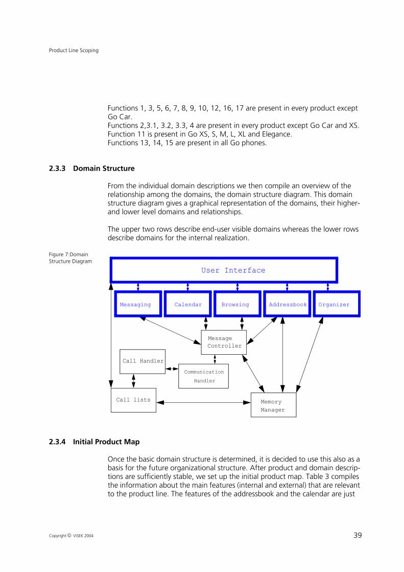
39
Product Line Scoping
Copyright ViSEK 2004
Functions 1, 3, 5, 6, 7, 8, 9, 10, 12, 16, 17 are present in every product except Go Car.Functions 2,3.1, 3.2, 3.3, 4 are present in every product except Go Car and XS.Function 11 is present in Go XS, S, M, L, XL and Elegance.Functions 13, 14, 15 are present in all Go phones.
2.3.3 Domain Structure
From the individual domain descriptions we then compile an overview of the relationship among the domains, the domain structure diagram. This domain structure diagram gives a graphical representation of the domains, their higher- and lower level domains and relationships.
The upper two rows describe end-user visible domains whereas the lower rows describe domains for the internal realization.
Figure 7:Domain Structure Diagram
.
2.3.4 Initial Product Map
Once the basic domain structure is determined, it is decided to use this also as a basis for the future organizational structure. After product and domain descrip-tions are sufficiently stable, we set up the initial product map. Table 3 compiles the information about the main features (internal and external) that are relevant to the product line. The features of the addressbook and the calendar are just
CommunicationHandler
Messaging Calendar
User Interface
AddressbookBrowsing
MessageController
Organizer
MemoryManager
Call Handler
Call lists
CommunicationHandler
Messaging Calendar AddressbookBrowsing
MessageController
Organizer
Memory
Call Handler
Call lists
Browsing
Manager

40
Product Line Scoping
Copyright ViSEK 2004
example functions. The message controller has more functions from these domains and additional functions from other domains (like browsing).
Table 3: Initial Product Map
domain feature subfeature Go Phones
XS S M L XL Car Ele-gance
Com Smart
Mes
sagi
ng
show new message flag
X X X X X X X X
show message basic show mes-sage
X X X X X X X X
show picture X X X X X X X
play sound X
show and save attached objects
X X X X X X X
show and save special message
X X X X X X X
new message or modify saved mes-sage
basic new mes-sage or modify saved message
X X X X X X X X
insert object in message
X X X X X X X
attach object to message
X X X X X X X
save drafted text element
X X X
browse folders X X X X X X X X
new folder X X X X X X X X
save message X X X X X X X X
delete saved mes-sage
X X X X X X X X
search for message X X X X X X X X
send message basic send mes-sage
X X X X X X X X
send chat mes-sage
X X X X X
choose drafted answer
X X X X X X
turn on/off T9 X X X X X X
compare word with T9
X X X X X X
start/ stop chat X X X X X

41
Product Line Scoping
Copyright ViSEK 2004
Mes
sage
Con
trol
ler:
feat
ures
for
mes
sagi
ng
search message by string
X X X X X X X X
split extended mes-sage
X X X X X X X
parse incoming mes-sage
basic parse incoming mes-sage
X X X X X X X X
parse for special message
X X X X X X X
parse for inserted objects
X X X X X X X
parse for attached objects
X X X X X X X
assemble outgoing message
X X X X X X X
send message X X X X X X X X
fetch object list X X X X X X X X
fetch message X X X X X X X X
save object X X X X X X X X
fetch folders X X X X X X X X
new folder X X X X X X X X
compare word with T9
X X X X X X
delete message X X X X X X X X
....
Mes
sage
Con
trol
ler:
feat
ures
for
add
ress
book delete addressbook
entryX X X X X X X X X
fetch addressbook entry
X X X X X X X X X
search addressbook entry by string
X X X X X X X X X
...
Mes
sage
Con
trol
ler:
fe
atur
es f
or c
alen
dar fetch calendar entry X X X X X X X X
save calendar entry X X X X X X X X
....
Table 3: Initial Product Map
domain feature subfeature Go Phones
XS S M L XL Car Ele-gance
Com Smart

42
Product Line Scoping
Copyright ViSEK 2004
2.4 Analyzing benefits and risks of domains
After an overall description of the product line has been performed, an assess-ment of the reuse potential and potential threats is performed. The approach is based on the domain potential assessment approach [21]. The method is based on an assessment approach where the evaluation framework was derived from existing literature on product line reuse, reuse surveys, and Fraunhofer IESE experience on product line reuse technology transfer. This evaluation framework is organized and justified in a top-down, GQM-like manner.
As different domains exhibit different characteristics with respect to the various dimensions relevant to reuse (e.g., maturity, number of systems they are rele-vant to, etc.), the domains will differ with respect to their potential for reuse. Consequently, each of these domains should be evaluated individually from a cost-benefit point of view with respect to its potential for reuse.
The assessment consists of two main steps:
Product Line Mapping — This first step aims at analyzing which areas of func-tionality (subsystems, domains) are relevant to the product line and which ones are not and what are their major contributions to the overall system functional-ity.The resulting domains can then be used as an input to detailed scoping for identifying the particular functionality that should be supported in a reusable manner by a reuse infrastructure
Reuse Potential — The second step aims at analyzing in more detail the identi-fied domains (subsystems) in particular with respect to. the reuse potential they embody.
The steps clearly build on top of each other. The first step provides a mapping of the domains, establishing their rough boundaries and their principal relations. Then, during the second step a coarse-grained analysis of the reuse potential is performed, meaning, those domains particularly relevant or irrelevant to prod-uct line reuse are determined. In more detail the approach provides the follow-ing results:
• The various sub-domains that are relevant to the systems in the product line are identified.
• The interactions among the sub-domains are determined.• Sub-domains within which the systems show no variance are identified.
(Here, no detailed scoping is necessary, as the corresponding components need to exist in all systems.)
• Sub-domains within which the systems show insufficient systematic varia-tion as their requirements are too customer-specific have been identified. (In cases where a detailed identification of the necessary variants is not possible, a detailed evaluation of the importance of the variants is not possible either.
43
Product Line Scoping
Copyright ViSEK 2004
The assessment is performed by making interviews with various stakeholders and evaluating the results. In the GoPhone Context the following stakeholders have to be considered:
• Marketing Department of GoPhone• Seasoned experts from TelCom• Mobile phone technology experts• Management of Go Phone (General Management and Project Management
The assessment process consists of three main phases: preparation, execution, and analysis. During the preparation phase a clarification of the objectives and the participating people is performed. This is followed by the detailed schedul-ing of the point in time when the various meetings are to happen. The results from Product line mapping are used to structure the interviews around the iden-tified subdomains and to focus the interviews on the planned products. An evaluation framework for the interviews in the form of questionnaires was developed. These questionnaires aim at identifying specific benefit and risk situ-ations for product line development. They were developed in a fashion based on the GQM-paradigm [23] and were augmented with information from existing domain assessment concepts and success factor studies. The different evalua-tion criteria were organized in seven different dimensions:
• Resource Constraints - Introducing domain engineering or product line devel-opment is usually linked to an additional overhead for developing the neces-sary infrastructure in the beginning. Sufficient resources for covering this start-up overhead need to be available in order for successfully starting a product line.
• Organizational Constraints - In order to establish a reuse program and keep it up and running, many organizational constraints need to be satisfied as oth-erwise the reuse program will simply run into problems due to fights within the organization and due to a lack of commitment and support from relevant levels.
• Market Potential external — the potential of selling the product on a market is central to any form of return on investment. Here, we focus on whether customers will buy the products that these assets are linked to. This is pre-condition so that sufficient products will be developed for amortization of the reuse investment.
• Market Potential internal — even if sufficient products could be built from the assets, the problem is whether sufficient internal demand from other business units exists. This is strongly related to the organizational problem of making the right units also take up the reusable assets.
• Maturity / Stability— how stable is the domain over time, do standards or books exist that give a common body of knowledge in the domain
• Commonality / Variability — the presence of sufficient commonality is a key requirement for reuse to happen, in particular the degree of commonality influences the reuse potential.

44
Product Line Scoping
Copyright ViSEK 2004
• Coupling / Cohesion — how strongly the domain is coupled with other domains influences how well the functionality can be encapsulated to pro-duce widely reusable assets.
• Existing Assets — the presence of existing assets can strongly help the perfor-mance of a reuse program, as it can provide significant start-up leverage. However, existing legacy systems may also be hindering as they need to be migrated to the new system structure or otherwise dealt with.
Each of these dimensions may point towards risks for product line development. However, not all dimensions will vary for all dimensions, e.g., organizational constraints may sometimes be constant across a subset of the domains, as the same organization is relevant for exploiting them. This is taken into account dur-ing the adaptation of the questionnaires.
After this adaptation has been performed we proceed with the actual analysis. This is based on interviews. Both the interviews themselves, as well as the latter evaluation of the results is driven from the questionnaires.
Based on the gathered information an initial analysis is performed and discussed with the interviewees in order to perform clarifications. Finally, the report with the analysis results is developed and discussed with the domain stakeholders.
Within the Go Phone Case Study we came to the following Assessment results:As we had no real development stuff we were just simulating the assessment results for this case study. So these results are just guesses of what could be typ-ical results in the situation of a development organization like GoPhone’s planned product line.
As the whole software development will be part of a single organizational unit, the corresponding factors• available resources• organizational constraints• market potential (internal)• market potential (external)are determined only once for all dimensions. Performing interviews on the dif-ferent domains of the product line lead to the following results:(We give the results here with numbers ranging from 0–3, with 3 being the most positive.)
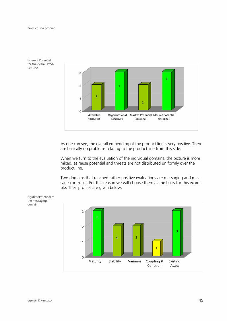
45
Product Line Scoping
Copyright ViSEK 2004
Figure 8:Potential for the overall Prod-uct Line
As one can see, the overall embedding of the product line is very positive. There are basically no problems relating to the product line from this side.
When we turn to the evaluation of the individual domains, the picture is more mixed, as reuse potential and threats are not distributed uniformly over the product line.
Two domains that reached rather positive evaluations are messaging and mes-sage controller. For this reason we will choose them as the basis for this exam-ple. Their profiles are given below.
Figure 9:Potential of the messaging domain
2
3
2
3
0
1
2
3
AvailableResources
OrganisationalStructure
Market Potential(external)
Market Potential(internal)
3
2 2
1
3
0
1
2
3
Maturity Stability Variance Coupling &Cohesion
ExistingAssets
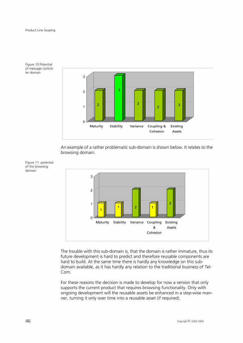
46
Product Line Scoping
Copyright ViSEK 2004
Figure 10:Potential of message control-ler domain
An example of a rather problematic sub-domain is shown below. It relates to the browsing domain.
Figure 11: potential of the browsing domain
The trouble with this sub-domain is, that the domain is rather immature, thus its future development is hard to predict and therefore reusable components are hard to build. At the same time there is hardly any knowledge on this sub-domain available, as it has hardly any relation to the traditional business of Tel-Com.
For these reasons the decision is made to develop for now a version that only supports the current product that requires browsing functionality. Only with ongoing development will the reusable assets be enhanced in a step-wise man-ner, turning it only over time into a reusable asset (if required).
2
3
22
2
0
1
2
3
Maturity Stability Variance Coupling &
Cohesion
Existing
Assets
11 2 1
2
0
1
2
3
Maturity Stability Variance Coupling
&
Cohesion
Existing
Assets

47
Product Line Scoping
Copyright ViSEK 2004
Identifying the most appropriate reusable assets
The domain potential assessment leads to a ranking of domains related to their reuse potential. So, the goal is to find those domains of the product line where reuse or generic implementation really pays.As the software development approach for Go-Phone Inc. is not yet established an approximate solution for determining reuse benefits is chosen. The approach is to use a model based on experience from TelCom with some adaptations to the specific situation. These adaptations are based on facts like: the software development team is smaller, that the development is performed in functionality-oriented groups that do development for different products (this should lower costs of development for reuse and with reuse), etc.
This information together with specific estimates of the relevant factors by the experts are the basis for the quantitative analysis.
As optimization goals for the reuse infrastructure the following goals are given:
Reduction of cost for development (weight:1)
Reduction of maintenance cost (weight:5)(High maintenance effort would block resources for future product develop-ment, leading to a delay in time-to-market)
Reduction of time-to-market for later products (weight 3.5)(Once the company made it to the market, it is of outmost importance to move fast and make a bold move for the market share of competitors.)
Recommendations from the analysis are given as usual on six levels:
A generic implementation of <feature> should be made available
A generic implementation of <feature> should be considered
In case of further products using <feature> a generic implementation of <fea-ture> should be developed
A generic interface to <feature> is strongly needed
A generic interface to <feature> is needed
Generic support for <feature> is currently not useful
The following rules were used for differentiating the classes (they take care of the fact that no probability information was available and that overall a certain

48
Product Line Scoping
Copyright ViSEK 2004
strategic interest in and tendency towards product line development was present).
The differentiation among the levels was done simply based on
The factor 9.5 derives from the sum of the weights for the different goals. Using this approach we can differentiate the different reuse levels by the value of r that needs to be achieved:
Note, that in this case we show only some arbitrary levels. In reality we would use more complex rules to identify the right levels.
Using this approach we identify the chat-related features in messaging as level 3, while the others are all level 1. In the message controller the T9 handling is level 2, while all other features are level 1. These results strongly reinforce the impression of a high reuse potential as it was already derived from the assess-ment.
With these results from scoping, we identified the domains with the highest reuse potential so in our further analysis we can concentrate on messaging and chat as their reuse will pay most.
Table 4: Relation between reuse level and reuse benefits
reuse level 1 2 3 4 5 6r >1 >0,3 >-0,1 >-0,2 >-0.4 else
r total reuse benefits 9.5 cost of single system development×------------------------------------------------------------------------------------------------------=
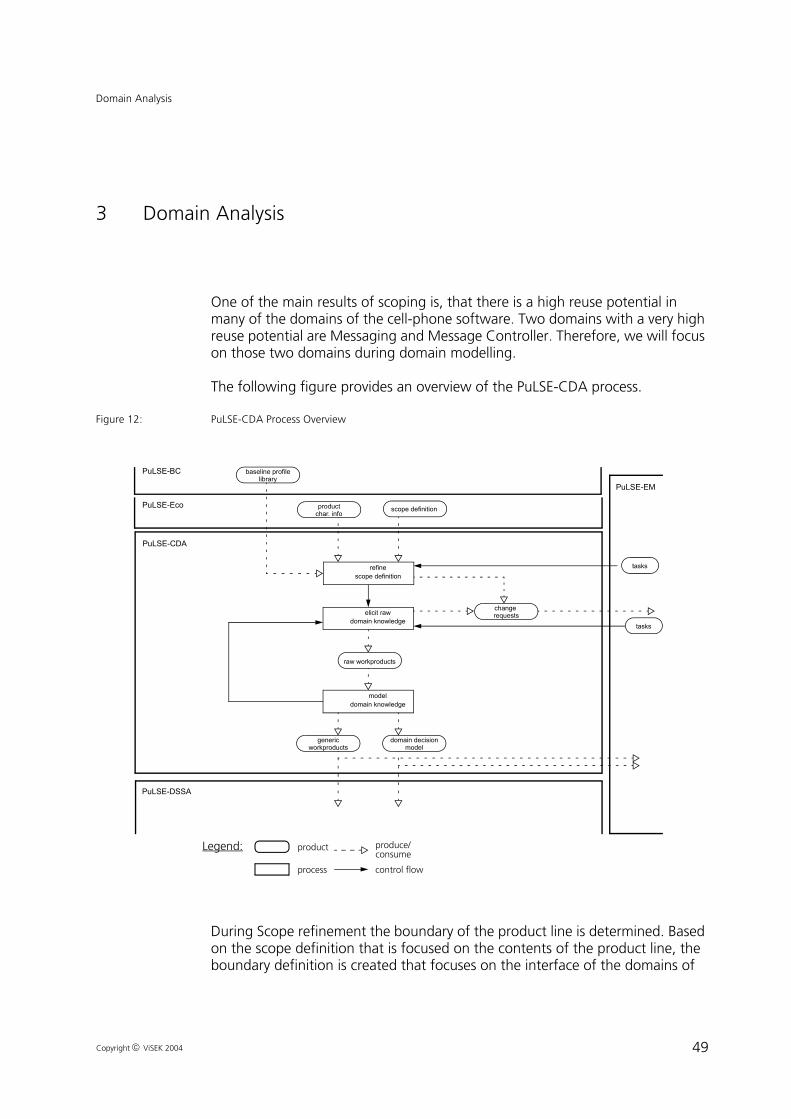
49
Domain Analysis
Copyright ViSEK 2004
3 Domain Analysis
One of the main results of scoping is, that there is a high reuse potential in many of the domains of the cell-phone software. Two domains with a very high reuse potential are Messaging and Message Controller. Therefore, we will focus on those two domains during domain modelling.
The following figure provides an overview of the PuLSE-CDA process.
Figure 12: PuLSE-CDA Process Overview
During Scope refinement the boundary of the product line is determined. Based on the scope definition that is focused on the contents of the product line, the boundary definition is created that focuses on the interface of the domains of
PuLSE-EM
PuLSE-CDA
elicit rawdomain knowledge
change requests
produce/
control flow
product
process
Legend:consume
modeldomain knowledge
refinescope definition
raw workproducts
PuLSE-DSSA
genericworkproducts
domain decisionmodel
PuLSE-BC baseline profilelibrary
PuLSE-Eco scope definitionproductchar. info
tasks
tasks

50
Domain Analysis
Copyright ViSEK 2004
the product line. The scope definition provides an initial structure for the domain information and the boundary definition limits the area to be analyzed.
To elicit raw domain knowledge, information is gathered from various sources. Sources may include books and other literature, human sources like domain experts, expected system users and application engineers or existing systems and their descriptions. At this point, the information is considered raw, because it is not necessarily well structured. Information may describe single systems sep-arately or it may be at an inadequate level of abstraction and detail, The raw information is written down and captured explicitly in workproducts / compo-nents. After modelling it might be necessary to go to this elicitation step again and elicit knowledge that is still missing in the models. So, there is an iteration between elicitation and modelling until the models are finalized and good enough as input for architecture. Elicitation and modelling are tightly coupled and there is no best way to combine them. Information may be directly elicited and modelled at the same time if necessary.
In Section 3.2 we focus on the domain modelling activity. In this step the raw elicited domain knowledge is restructured by introducing improved abstractions, that is use-cases. Also, all systems in the domain are integrated into the model through variabilities, which capture the differences among the systems within the domain. After modelling the information is called generic instead of raw because it covers the whole product line, as opposed to, single systems.
In order for the variabilities to be managed efficiently PuLSE-CDA uses decision models (see Section 3.4). These describe the captured variabilities as decisions, possible resolutions along with the actions following a resolution. There are two types of decision models: the workproduct and the domain decision models. Workproduct decision models structure variability within one workproduct hier-archically. The domain decision model aggregates the different workproduct decision models and adds higher level decisions that subsume top-level deci-sions of workproduct decision models. The domain decision model contains a set of domain decisions, which, when resolved, instantiate the complete domain model to the specific requirements of one product line member.
3.1 Customization of PuLSE CDA
The PuLSE CDA Approach for domain modelling is a highly customizable approach. Depending of the context and the constraints of the product line to be built, modelling techniques are selected and workproducts to be built are determined during the customization phase. Figure 13 shows the factors influ-encing the customization. In the case of the cell phone Product Line of Go-Phone Inc. especially of the messaging and message controller domain, the fol-lowing customization factors are important:

51
Domain Analysis
Copyright ViSEK 2004
• The domain maturity and domain stability are extremely low• There are no existing systems• Many different information sources are available, but no users and experi-
enced application engineers yet.• There are enough resources but the project skills are not too high because it
is a new project• Business objectives and enterprise skills are good
Figure 13:Customi-zation of the PuLSE CDA approach
This leads to the following decisions concerning the modelling method and the workproducts:
• As there is no legacy information we have to integrate, we do not have to use an old modelling paradigm, so we can use UML.
• As Mobile Phones are highly interactive, it is reasonable to model Use Cases• To express Variability, feature modelling is used. The basic features can be
extracted from the product feature map and the use-cases. Those features can be modeled with a FODA-like notation which is compatible to the Tool to be used (Visio)
• Functional and non Functional requirements are integrated into the use-case, so there are no explicit textual requirements.In the remainder of this section we describe the artifacts we produced and the formalisms and steps we took to produce them.
Level of
Detail
Domain
Maturity
Project Characteristics Enterprise
Application
Type
Existing
Systems
Domain
ExpertsPersonnel
Application
Engineers
Business
Objectives
Tool
Support
Enterprise
Skills
Time
Money
Resources
Domain Characteristics
Modelling
Process
Information
Gathering
Domain
Stability
BusinessArea
Abstractions
Domain Attributes Domain Info.
Information SourcesIntegratableSW Artifacts
Coverage
Domain
Size
Domain
ComplexityPapers Users
Books Standards
Project
Skills
Goal
Category
Information
TypeParadigm
Workproduct
Types
Workproduct
Representation

52
Domain Analysis
Copyright ViSEK 2004
3.2 Use Case Modelling
Use cases are used for single system requirements engineering to capture requirements from an customer/user point of view. When utilizing use cases for product line modelling they have to be extended with a variability mechanism. Stereotypes can be used as this variability mechanism for use case diagrams and textual use cases. This early and explicit variability in the product line lifecycle supports the domain experts in establishing a variability mindset and supports explicit instantiation during application analysis. A use case describes how the system is used by a user. Use cases are used during the analysis phase to identify and partition system functionality. A use case describes the actions of an actor when following a certain task while interacting with the system to be described. A use case diagram includes the actors, the system, and the use cases them-selves. The set of functionality of a given system is determined through the study of the functional requirements of each actor, expressed in the use cases in the form of common interactions. So a use-case diagrams in UML 1.4 consists of [24]:
• The system• The use cases within the system• The actors outside the system• Relationships between actors and use-cases: • associations, generalization, include, and extend
Associations denote the participation of an actor in a use case, a generalization relation means that there is a specialization of one use case or actor to another. An extend relationship indicates that an instance of a use case may be aug-mented by the behavior specified by another use case and the include relation-ship indicates that an instance of a use case will contain the behavior of another use case.
In use case diagrams, any model element may potentially be variant in a prod-uct-line context. An actor is variant, for example, if a certain user class is not supported by a product. A use case is variant if it is not supported by some prod-ucts in the family. Those variants can be alternatives, optional elements or value ranges for certain elements. Whether it is an optional use case or whether it is an alternative to another use case is captured outside of the use-case diagram in a decision model. This is done simply because this information would overload the use-case diagram, make it less readable, and thus less useful. During appli-cation engineering, for each variant use case, it is decided whether the use case is (or is not) supported by the product to be built. The instantiation is done then with the help of the decision model. In a textual use case description any text fragment may be variant. Variant text fragments are explicitly marked by pairs of the XML-like tags <variant> and </variant>.

53
Domain Analysis
Copyright ViSEK 2004
During the domain analysis phase we produced the Use Cases which are impor-tant for the messaging domain. We refined the results from scoping, in this case the domain description and the main features of the messaging domain by building use cases around the main features. Concerning the Use Case level of abstraction (see [18]), three Use Cases are on a user level, i.e. it is a level where you can discuss the content of the Use Case with a potential user, it is not to detailed and not to abstract.These Use Cases on user level are the Use Case to send a newly composed message, the Use Case to show a message and the one to start a chat. The Use Case to view and save a calendar entry is on subfunction level which means it is more detailed than a Use Case on user level. This type of Use Case was modelled in addition to the user level Use Cases to show how the messaging component interacts with the message controller component. The following UC-Diagram shall give an overview on the modelled Use Cases and shows the dependencies between the actors and the various Use Cases as well as the dependencies between the Use Cases.
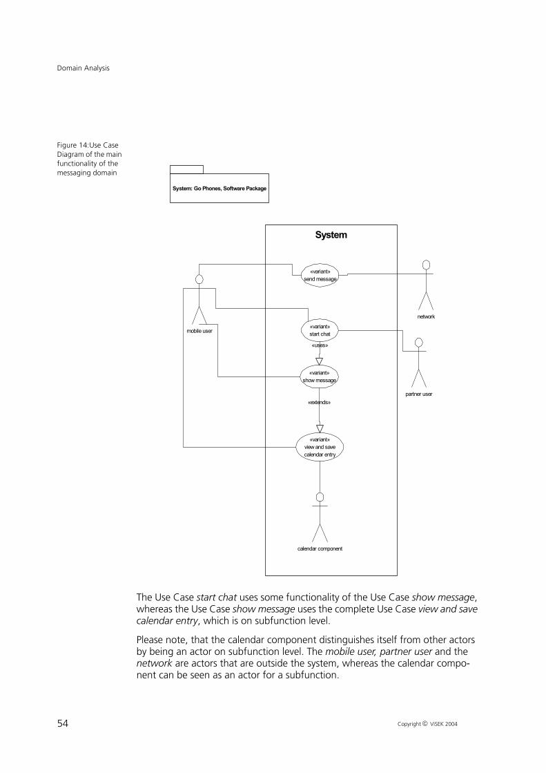
54
Domain Analysis
Copyright ViSEK 2004
Figure 14:Use Case Diagram of the main functionality of the messaging domain
The Use Case start chat uses some functionality of the Use Case show message, whereas the Use Case show message uses the complete Use Case view and save calendar entry, which is on subfunction level.
Please note, that the calendar component distinguishes itself from other actors by being an actor on subfunction level. The mobile user, partner user and the network are actors that are outside the system, whereas the calendar compo-nent can be seen as an actor for a subfunction.
System
«variant»send message
«variant»show message
«variant»start chat
«variant»view and savecalendar entry
mobile user
network
calendar component
«extends»
«uses»
partner user
System: Go Phones, Software Package

55
Domain Analysis
Copyright ViSEK 2004
The Use Cases were modelled by using a template that uses tags for all elements of the Use Case. The used template is a modification of the template suggested by Alistair Cockburn (see [18]). In the following, a short description of the tags is given:
Use Case name: The name of the Use Case. The stereotype ’<<variant>>’ before the UC name shows a special kind of variability: a variability that holds for the complete UC. The semantics is the same as if an nil-alternative (∅) would be added to each step of the main success scenario (and the extensions).
Primary actor: A stakeholder that calls on the system to deliver one of its ser-vices. He has a goal with respect to the system which can be satisfied by suc-cessful completion of the Use Case.
Scope: The scope defines the system under discussion. It sets the borders for the range of the Use Case.
Level: Defines on which level the Use Case is written. A Use Case can be on a high level, called summary level, on medium level called user level or on a quite low level called subfunction level.
Stakeholders and interests: All stakeholders and their interests shall be described in this section of a Use Case.
Precondition: States, what must be true before the Use Case starts.
Minimal Guarantee: States what will always be achieved after running the Use Case, even if it was not successful.
Success Guarantee: States what will be achieved, if the Use Case was com-pleted successfully.
Main Success Scenario: Describes a typical run of the Use Case where nothing goes wrong.
Extensions: Describes what can happen differently during the scenario.
Non-functional requirements: States the non-functional requirements that are valid for the Use Case.
The underlined questions in the Use Cases reflect a decision model for each Use Case. It would have also been possible to extract this information and package it in a stand-alone decision model on a Use Case level of abstraction. The reason, why we decided to include the decision model (Use Case level) in the Use Case was to support better readability and an all-in-one description.
In the following, the four Use Cases send message, show message, start chat and view and save calendar entry, modelled with the explained template, are described.

56
Domain Analysis
Copyright ViSEK 2004
3.2.1 Use Case Send Message
1 Use Case name
<<VARIANT>> Send message (all Go Phones except Go Car.Go Car has no messaging domain.)
2 Primary actor
mobile user
3 Scope
Software Package of Go Phones, Messaging domain
4 Level
user level
5 Stakeholders and interests
• mobile user (in the following ’user’): wants to send a newly composed text-message
• network: wants to receive protocol conform messages from the mobile
6 Precondition
The system shows the main menu.
7 Minimal Guarantee
The mobile keeps operating.
8 Success Guarantee
The message, entered by the user is sent via the network, so that the message reaches its destination in the same shape and content as the user typed it.
9 Main Success Scenario
1. The user chooses the menu-item to send a message.
2. The user chooses the menu-item to start a new message.
3. Are there various message types?
<OPT> The system asks the user which kind of message he wants to send. (Go Phone S, M, L, XL, Elegance, Com, Smart)
4. The system switches to a text editor.
5. The user enters the text message.
6. Is T9 supported?
<ALT 1> If T9 is activated, the system compares the entered word with the dictionary. (Go Phone XS, S, M, L, XL, Elegance)
57
Domain Analysis
Copyright ViSEK 2004
7. Which kind of objects can be inserted into a message?
<ALT 1> The user can insert a picture into the message (Go Phone S, M, L, XL)
<ALT 2> The user can insert a picture or a drafted text-element into the mes-sage. (Go Phone Elegance, Com, Smart)
<ALT 3> ∅ (Go Phone XS)
8. Which kind of objects can be attached to a message?
<ALT 1> The user can attach files, business cards, calendar entries or sounds to the message. (Go Phone Smart)
<ALT 2> The user can attach business cards or calendar entries to the mes-sage.(Go Phone S, M, L, XL, Elegance, Com)
<ALT 3> ∅ (Go Phone XS)
9. The user chooses the menu-item to send the message.
10. The system asks the user for a recipient.
11. Which kind of message will be sent?
<ALT 1> The user types the phone number or chooses the recipient from theaddressbook.(Go Phone XS, S, M, L, XL, Elegance)
<ALT 2> In case of a basic or extended SMS, the user types the phone num-ber or chooses the recipient from the addressbook. In case of an email, the user types the email-address or chooses the recipient from the addressbook. (Go Phone Com, Smart)
12. The system connects to the network and sends the message, then the sys-tem waits for an acknowledgement.
13. The network sends an acknowledgement to the system.
14. The system shows an acknowledgement to the user that the message was successfully sent.
15. Is a sent message directly saved in the sent-message folder?
<ALT 1> The system asks the user if the message should be saved. If it should be saved, the system saves the message in the ‘sent-message’ folder (Go Phone XS, S, M, L, XL, Elegance)
<ALT 2> The system saves the message in the ‘sent-message’ folder.(Go Phone Com, Smart)
16. The system switches to the main menu.
10 Extensions:
2 a) The system does not have enough free memory for composing a new mes-sage. The system states an error message.

58
Domain Analysis
Copyright ViSEK 2004
5 a) The user enters a symbol the system does not understand. The system shows the user that it does not understand the symbol (e.g. playing a beep tone).
6 a) Is T9 supported?
<OPT> The user enters a letter. T9 does not find a match. The system shows the user that it does not understand the word (e.g. playing a beep tone). (The user has the possibility to switch T9 off now or enter the word manually).
12 a) The system tries to connect to the network and gets no response. The sys-tem tries again after a number of milliseconds (to be specified). If this try fails again, the system states a message that the message was not sent and the mes-sage is saved in the ‘outbox’ folder.
13 a) The network does not send an acknowledgement: The system tries again after a number of milliseconds (to be specified). If this try fails again, the system states a message that the message was not sent and the message is saved in the ‘outbox’ folder.
13 b) The network sends a message that the message can not be delivered/ is invalid. The system states a message that the message was not sent and the message is saved in the ‘outbox’ folder.
1-16)There is an incoming call during the Use Case: The current status is saved and the call is displayed. After the call the saved state is reestablished.
The user can terminate the UC via a menu item after steps 1,2, 3, 4,5,6,7,8,9,10,11,14 and 15.
11 Non-functional requirements
• After the user chose send message the message has to be sent to the net-work within 2 sec.
• The text editor must provide easy navigation functionality (high usability). This usability is measured by the use of a customer questionnaire in which more than 60% of the questioned customers rate the usability at least ‘good’ on a scale: very bad, bad, average, good, very good. Furthermore, the time to edit one letter in a message with about 100 letters must be lower than 3 sec.
• The error-rate for sending messages should be below 0.2%. This rate does only cover errors caused by the mobile, e.g. messages that are not conform to the network-protocol.
3.2.2 Use Case Show Message
1 Use Case name

59
Domain Analysis
Copyright ViSEK 2004
<<VARIANT>> Show message(All Go Phones except Go Car. Go Car has no messaging domain.)
2 Primary actor
mobile user
3 Scope
Software Package of Go Phones, Messaging domain
4 Level
user level
5 Stakeholders and interests
• mobile user (in the following ’user’): wants to see the content of a mes-sage
6 Precondition
The system shows the main menu.
7 Minimal Guarantee
The mobile keeps operating.
8 Success Guarantee
The message, chosen by the user, is displayed with all its components (e.g. sound, picture, business cards).
9 Main Success Scenario
1. The user chooses the menu-item to show a message.
2. The system shows a list of all available folders.
3. The user browses the folders until he reaches his destination folder.
4. The system displays a list of all available messages.
5. The user chooses one message to be displayed.
6. Which components of a message are directly displayed when the message is displayed?
<ALT 1> The system displays the text. If a sound is attached, the system plays the sound. If the message contains an inserted picture, the system displays the picture. (Go Phone Smart)
<ALT 2> The system displays the text. If the message contains an inserted picture, the system displays the picture. (Go Phone S, M, L, XL, Ele-gance, Com)

60
Domain Analysis
Copyright ViSEK 2004
<ALT 3> The system displays the text. (Go Phone XS)
7. Is the phone capable of attachments?
<OPT> The system shows that the message has an attachment. (Go Phone S, M, L, XL, Elegance, Com, Smart)
8. Is the phone capable of attachments?
<OPT> The user chooses the menu-item ‘view attachment’.(Go Phone S, M, L, XL, Elegance, Com, Smart
9. Is the phone capable of attachments?
<OPT> The system displays a list of all attachments. (Go Phone S, M, L, XL, Elegance, Com, Smart)
10. Is the phone capable of attachments?
<OPT> The user chooses an attachment. (Go Phone S, M, L, XL, Elegance, Com, Smart)
11. Which kind of objects can be displayed by the phone?
<ALT 1> If the attachment is a file, the system asks the user where to save the file. The user enters the destination and the system saves the file to this destination. If the attachment is a business card, the system shows the business card and asks the user whether it should be saved. If the user wants to save the business card, the system saves the business card in the address book.If the attachment is a calendar entry, the system shows the calendar entry and asks the user whether it should be saved. If the user wants to save the calendar entry, the system saves the calendar entry in the calendar.(Go Phone Smart)
<ALT 2> If the attachment is a business card, the system shows the business card and asks the user whether it should be saved. If the user wants to save the business card, the system saves the business card in the address book.If the attachment is a calendar entry, the system shows the calendar entry and asks the user whether it should be saved. If the user wants to save the calendar entry, the system saves the calendar entry in the calendar.(Go Phone S, M, L, XL, Elegance, Com)
<ALT 3> ∅. (Go Phone XS)
10 Extensions:
4 a) There are no messages. The following steps (5-11) can not be performed. The user can browse to another folder or leave to the main menu.

61
Domain Analysis
Copyright ViSEK 2004
6 a) What kind of special messages is the phone capable of?
<ALT 1> If the message contains Wap-settings, the system shows the Wap-settings and asks the user, whether the Wap-settings should be saved. If the Wap-settings should be saved, it saves the Wap-set-tings.If the message is a screensaver, the system shows the screensaver and asks, if it should be saved. If it should be saved, it saves the screensaver. If the message is a special message of an unknown type, the system displays an error- message indicating that the message can not be displayed.(Go Phone M, L)
<ALT 2> If the message contains Wap-settings, the system shows the Wap-settings and asks the user, whether the Wap-settings should be saved. If the Wap-settings should be saved, it saves the Wap-set-tings. If the message is a special message of an unknown type, the system displays an error- message indicating that the message can not be displayed.(Go Phone Com, Smart)
<ALT 3> If the message is a screensaver, the system shows the screensaver and asks, if it should be saved. If it should be saved, it saves the screensaver. If the message is a special message of an unknown type, the system displays an error- message indicating that the message can not be displayed.(Go Phone S, XL, Elegance)
<ALT 4> The system is not capable of special messages. Therefore, if the message is a special message, the system displays an error-message, indicating that the message can not be displayed. (Go Phone XS)
11 a) The attachment is of an unknown type. The system states an error-mes-sage, indicating that the attachment can not be displayed.
1-11) There is an incoming call during the Use Case: The current status is saved and the call is displayed. After the call the saved state is reestablished.
The user can terminate the UC via a menu item after steps 1,2, 3, 4,5,6,7,8,9,10 and 11.
11 Non-functional requirements
• The system shall always display ‘readable content’. If the system can not understand some type of content, it must not be displayed.

62
Domain Analysis
Copyright ViSEK 2004
3.2.3 Use Case Start Chat
1 Use Case name
<<VARIANT>> Start chat(All Go Phones except Go Car, XS, S and Com. Go Car has no messaging domain. Go XS, S and Com do not have a chat func-tionality.)
2 Primary actor
mobile user
3 Scope
Software Package of Go Phones, Messaging domain
4 Level
user level
5 Stakeholders and interests
• mobile user (in the following ’user’): wants to chat with another user (partner user) via sms
• network: wants to receive protocol conform messages from the mobile• partner user: wants to chat with the mobile user
6 Precondition
The system shows the main-menu.
7 Minimal Guarantee
The mobile keeps operating.
8 Success Guarantee
The message, entered by the user, is sent via the network, so that the message reaches the partner user in the same shape and content as the user typed it. The user receives messages from the partner user.
9 Main Success Scenario
1. The user chooses the menu-item to start the chat.
2. The system asks the user to choose a partner for chat.
3. The user either enters a phone number or he chooses a partner via the address book.
4. The system starts chat mode. The display in now divided into two parts: one part displays the chat messages and is called ‘chat window’. Another part is

63
Domain Analysis
Copyright ViSEK 2004
a special kind of text editor (smaller field for typing compared to the normal text-editor) called ‘editor window’
5. The user enters the text message.
6. Is T9 supported?
<OPT> If T9 is activated, the system compares the entered word with the dictionary. (Go Phone M, L, XL, Elegance)
7. Which kind of objects can be inserted into a message?
<ALT 1> The user can insert a picture into the message.(Go Phone M, L, XL)
<ALT 2> The user can insert a picture or a drafted text-element into the mes-sage. (Go Phone Elegance, Smart)
8. Which kind of objects can be attached to a message?
<ALT 1> The user can attach files, business cards, calendar entries or sounds to the message.(Go Phone Smart)
<ALT 2> The user can attach business cards or calendar entries to the mes-sage.(Go Phone M, L, XL, Elegance)
9. The user chooses the menu-item to send the chat message.
10. The system connects to the network and sends the message, then it waits for an acknowledgement.
11. The network sends an acknowledgement to the system.
12. The system displays the content of the sent message in the chat window.
13. If the system receives a message from the partner user, it displays the mes-sage according to the Use Case ‘show message’ steps 5 and the following, but the messages are displayed in the chat window.
How many messages can be displayed in the chat window?
<ALT 1> The system can display up to 3 messages in the chat window.(Go Phones M, L, XL))
<ALT 2> The system can display up to 5 messages in the chat window.(Go Phones Elegance, Smart)
14. The user can now terminate the chat or he can repeat steps 5 to 13.
10 Extensions:
1 a) The system does not have enough free memory to start a chat. The system states an error message.

64
Domain Analysis
Copyright ViSEK 2004
5 a) The user enters a symbol the system does not understand. The system shows the user that it does not understand the symbol (e.g. playing a beep tone).
6 a) Is T9 supported?
<OPT> The user enters a letter. T9 does not find a match. The system shows the user that it does not understand the word (e.g. playing a beep tone). (The user has the possibility to switch T9 off now or enter the word manually).
10 a) The system tries to connect to the network and gets no response. The sys-tem tries again after a number of milliseconds (to be specified). If this try fails again, the system states a message that the message was not sent and the mes-sage is saved in the ‘outbox’ folder. The system asks the user if he wants to stop the chat.
11 a) The network does not send an acknowledgement: The system tries again after a number of milliseconds (to be specified). If this try fails again, the system states a message that the message was not sent and the message is saved in the ‘outbox’ folder. The system asks the user if he wants to stop the chat.
11 b) The network sends a message that the message can not be delivered/ is invalid. The system states a message that the message was not sent and the message is saved in the ‘outbox’ folder. The system asks the user if he wants to stop the chat.
13 a) The system receives an unknown message type. The system displays an error message that the received message can not be displayed.
There is an incoming call during the Use Case: The current status is saved and the call is displayed. After the call the saved state is reestablished.
The user can terminate the UC via a menu item after steps 1,2, 3, 4,5,6,7,8,9,12 and 13.
11 Non-functional requirements
• After the user chose send message the message has to be sent to the net-work within 2 sec.
• The text editor must provide easy navigation functionality (high usability). This usability is measured by the use of a customer questionnaire in which more than 60% of the questioned customers rate the usability at least ‘good’ on a scale: very bad, bad, average, good, very good. Furthermore, an easy switch to earlier chat messages of the same session must be possi-ble.
• The error-rate for sending messages should be below 0.2%. This rate does only cover errors caused by the mobile, not by the network.

65
Domain Analysis
Copyright ViSEK 2004
• The user and the partner user shall have the feeling of a conversation. Therefore, the time between transmission and reception should be shorter than 5 sec. (Maybe higher priority for chat messages)
3.2.4 Use Case View and Save calendar entry
1 Use Case name
<<VARIANT>> View and save calendar entry(All Go Phones except Go Car and XS. Go Car has no messaging domain. Go XS has no possibility to attach calendar entries to a message.)
2 Primary actor
mobile user
3 Scope
Software Package of Go Phones, Messaging domain
4 Level
subfunction level
5 Stakeholders and interests
• mobile user (in the following ’user’): wants to view and save a calendar entry which is attached to a message he received.
• calendar component: wants to accept the new entry and maintain a con-sistent state.
6 Precondition
The user chose the menu-item to view the attachments of a message.
7 Minimal Guarantee
The mobile keeps operating, the state of the calendar stays consistent.
8 Success Guarantee
The attached calendar entry is displayed and saved via the calendar domain.
9 Main Success Scenario
1. The messaging component displays a list of all attachments via the UI.
2. The user chooses a calendar entry attachment.
3. The messaging component sends a request to the message controller that the attached calendar entry should be displayed.

66
Domain Analysis
Copyright ViSEK 2004
4. The message controller sends a request to the calendar component to show the calendar and highlight the newly received calendar entry.
5. The calendar component shows the calendar with the highlighted entry via the UI and asks the user if he wants to save the new calendar entry.
6. The user confirms the saving of the calendar entry.
7. The calendar component sends a request to the message controller to save the calendar entry.
8. The message controller saves the calendar entry.
9. The messaging component displays a list of all attachments via the UI. (com-pare step 1)
10 Extensions:
5a) The calendar entry has a not-known or invalid format. The calendar domain shows an error message via the UI. Step 9 is directly performed.6a) The user does not want to save the calendar entry. Steps 7 and 8 are left out and step 9 is directly performed.
The user can terminate the UC via a menu item after steps 1,2 and 5.
11 Non-functional requirements
• After the user chose a calendar entry to be viewed, the calendar with the highlighted entry shall be displayed within 0.5 sec.
• The new calendar entry should be highlighted clearly. In a questionnaire with new users, at least 95% must directly understand which entry is the new entry.
• After the user confirmed the saving of the entry, the attachment list (step 9) shall be displayed within 0.3 sec.
• The rate of errors due to invalid calendar entry formats should be below 0.02%.
• There shall be always enough buffer in memory for saving calendar entries.
3.3 Feature Modelling
According to the Use Cases on user level, a variability and feature model for each Use Case was build. In the following, those variability models will be pre-sented. The models are feature models according to the notation developed in Foda (see [17]). The notation for these variability models consists of elements that will be explained by the following examples:

67
Domain Analysis
Copyright ViSEK 2004
Figure 15:Example model for ’consist of’
This example model describes that the feature send message consists of a recipient and a network.
Figure 16:Example model for ’optional’
This example model describes that the text editor consists of an obligatory text and an optional insert object. A circle at the end of a link to an object always symbolizes an optionality. This optionality refers to the fact that product A of the product line has text and an insert object, whereas product B does only have text.
send message
networkrecipient
text editor
insert objecttext

68
Domain Analysis
Copyright ViSEK 2004
Figure 17:Example model for ’XOR’
This example model describes that a message is either an email, a basic short message or an extended short message. Furthermore, email and extended short message are optional. E.g. a product A is capable of basic and extended short messages. If a message is composed on this mobile, a message can either be a basic or a short message.
This model comprises three kinds of variability:
• first, variability resulting from inheritance (email, basic and extended short messages are all different kind of messages)
• second, variability resulting from the modelling process (optionality: phone A is capable of emails, phone B not)
• third, runtime variability (XOR: the user decides during runtime if he wants to send an email or a short message)
In the following, the variability models for each Use Case are presented.
message
email basic short message extended short message
{XOR} {XOR}

69
Domain Analysis
Copyright ViSEK 2004
Figure 18:Variability model for UC send message
Besides other information, the model shows that a message is either a basic short message, an email (if the phone is capable of emails) or an extended short message (if the phone is capable of extended ones). Furthermore, a basic short message can be a normal message, a Wap-setting, or a Screensaver (if the phone is capable of Wap-settings and screensaver). Moreover, a text editor con-sists of text and maybe of a T9 component, attachable objects and insertable objects, depending on the phone.
send message
message
text editor
networkrecipient
email addressphone number
{XOR}
email basic short message extended short message
{XOR} {XOR}
normal ScreensaverW AP-setting
{XOR} {XOR}
T9insert objecttextattach object
picture drafted text elementsound business card calender entry file

70
Domain Analysis
Copyright ViSEK 2004
Figure 19:Variability model for UC show message
Besides other information, the Use Case shows that a message can be a normal or a special message (if the phone is capable of special messages). A normal message consist of text and probably sound and picture. A special message may be a screensaver or a Wap-setting.
show message
message folders
normal message special message
{XOR}
text Screensaver WAP-setting
attachment
picturesound
business card calender entry file
{XOR}

71
Domain Analysis
Copyright ViSEK 2004
Figure 20:Variability model for UC start chat
In contrast to composing a normal short message, the chat additionally consists of windows. E.g. the chat window consists of a message which can be an email, a basic or an extended short message, similar to the variability model of the send message Use Case.
start chat
message
text editor
networkrecipient
email addressphone number
{XOR}
email basic short message extended short message
{XOR} {XOR}
normal ScreensaverWAP-setting
{XOR} {XOR}
T9insert objecttextattach object
picture drafted text elementsound business card calender entry file
windows
chat window editor window

72
Domain Analysis
Copyright ViSEK 2004
3.4 Decision Modelling
In order to instantiate the models, we need a decision model. The following decision model in tabular form describes what effects decisions on features of the products have. The table states questions one has to ask himself when instantiating a product. The questions belong to a subject and the answer to the questions (resolution) triggers effects that instantiate the Use Cases.
Table 5: Decision model
ID Question Subject Resolution Effect
1 Which kind of attach-ments is the phone capa-ble of?
Attach-ments
files, sounds, business cards and calendar entries
remove Alt 2 and 3 from step 8 in UC ’send message’;remove Alt 2 from step 8 in UC ’start chat’;remove Alt 2 and 3 from step 11 in UC ’show message’;steps 7 to 10 of UC ’show message’ are obliga-tory;remove Alt 2 and 3 from step 6 in UC ’show message’.
business cards and calendar entries
remove Alt 1 and 3 from step 8 in UC ’send message’;remove Alt 1 from step 8 in UC ’start chat’;remove Alt 1 and 3 from step 11 in UC ’show message’;steps 7 to 10 of UC ’show message’ are obliga-tory;remove Alt 1 from step 6 in UC ’show mes-sage’.
no objects remove Alt 1 and 2 from step 8 in UC ’send message’;remove Alt 1 and 2 from step 11 in UC ’show message’;remove steps 7 to 10 from UC ’show message’;remove Alt 1 from step 6 in UC ’show mes-sage’.

73
Domain Analysis
Copyright ViSEK 2004
The decision, to choose elements in a field of the type ’resolution’ is an xor deci-sion, i.e., non of the elements can be combined.
2 Which kind of insert-able objects is the phone capable of?
Inserts pictures remove Alt 2 and 3 from step 7 in UC ’send message’;remove Alt 2 from step 7 in UC ’start chat’;remove Alt 3 from step 6 in UC ’show mes-sage’.
pictures and drafted text-elements
remove Alt 1 and 3 from step 7 in UC ’send message’;remove Alt 1 from step 7 in UC ’start chat’;remove Alt 3 from step 6 in UC ’show mes-sage’.
no items remove Alt 1 and 2 from step 7 in UC ’send message’;remove Alt 1 and 2 from step 6 in UC ’show message’.
3 T9 support? T9 yes step 6 of UC ’send message’ is obligatory;extension 6a of UC ’send message’ is obliga-tory;step 6 of UC ’start chat’ is obligatory;extension 6a of UC ’start chat’ is obligatory.
no remove step 6 of UC ’send message’;remove extension 6a of UC ’send message’;remove step 6 of UC ’start chat’;remove extension 6a of UC ’start chat’.
4 Which kinds of messages are sup-ported?
mes-sage types
short mes-sages and email
step 3 of UC ’send message’ is obligatory;remove Alt 1 from step 11 in UC ’send mes-sage’.
only short messages
remove step 3 of UC ’send message’;remove Alt 2 from step 11 in UC ’send mes-sage’.
Table 5: Decision model
ID Question Subject Resolution Effect

74
Product Line Architecture
Copyright ViSEK 2004
4 Product Line Architecture
A software architecture is the mediating product between requirements from a problem-domain perspective and the software solution for the specified prob-lem with means out of the solution domain. Our understanding of software architecture corresponds to the definitions given in [16].
This chapter provides an overview of the architecture defined for the mobile phone domain and the requirements given in the previous chapters. Here, the description of the architecture will be mainly technology- (or platform-) unspe-cific.
The description of the architecture is structured as follows: Section 4.1 captures the conceptual view on the architecture. It introduces the main conceptual enti-ties and the roles they play in term of architectural styles and patterns. Section 4.2 refines the conceptual view and brings the conceptual entities into a logical structure using the KobrA method. Section 4.3 gives an overview of mecha-nisms used to deal with the variability in the architecture required to support all expected and anticipated variations in mobile phone products of today and in the future.
4.1 Architectural Styles & Patterns
During architectural design it is useful to take architectural styles and patterns into account because they reflect best practices for dealing with known prob-lems. In this work we are dealing with a software product line that has numer-ous variabilities and therefore we consider flexibility as a main requirement on the architecture.
Component orientation is the starting point for achieving flexibility in the GoPhone product line. To this end we are making use of the KobrA method described earlier. Furthermore we consider well know architectural patterns to realize our component oriented design. These are presented in the following paragraphs.
4.1.1 Mediator Pattern
The Mediator pattern (see [1]) is one of the most famous architectural styles for achieving changeability and extensibility of components. The main goal of the pattern is to avoid direct interactions between components by introducing a

75
Product Line Architecture
Copyright ViSEK 2004
central component, i.e the Mediator, that handles all the communications between them. The following picture shows the effect of introducing a Media-tor into a web of interconnected components.
Figure 21:The Medi-ator pattern
The Mediator pattern enhances the reusability of components since they only need to know the interface to the mediator and not to any other components. Moreover it facilitates incremental development as proposed by the PuLSE-DSSA method because components can be added to the architecture without a great impact as long as they adhere to the Mediator interface.
In the later and more detailed design phase we refine the Mediator towards a Component Manager since it assumes additionally the responsibility of the life-cycle management of components.
To separate graphical component management from the rest of the functional-ity according to the MVC paradigm (see [1]) we introduce during refinement a special Component Manager, namely a View Controller.
4.1.2 State pattern
Mobile phones have small displays that make it impossible to display at the same time all information required for an operation. So in order to complete an oper-ation the user has to go through a series of steps each one displayed in a sepa-rate screen. For example the message sending scenario contains typically the fol-lowing screens:
Desktop → Main Menu → Messaging Menu → Edit Text → Enter Recipient → Options Menu → Confirm message sending
Web of interconnected components
Withouta Mediator
Star configuration
Witha Mediator
Mediator

76
Product Line Architecture
Copyright ViSEK 2004
Each step can be seen as a state with predefined entry and exit actions. This leads us to the conclusion that state management is crucial for the mobile phone operation. For this reason we decided to use the State Pattern (see [1]).
The idea of the State Pattern is that a component (i.e. Send Message Compo-nent) contains a set of state components each one encapsulating a specific functionality. Whenever the component needs to change state, it changes the current state component and delegates control it.
The following picture shows how the above example of the Send Message sce-nario can be realized with the State Pattern.
Figure 22:The State Pattern
As shown in the picture the Main Menu State interacts directly with a Messag-ing component. This brings up a mismatch with the Mediator pattern presented before. Thus we decided to combine the Mediator and State patterns.
4.2 The KobrA process
Goal of this section is to give an overall idea of applying the KobrA process for creating component-based systems. Covering the complete process goes beyond the scope of this report. For that reason many details are left out from the diagrams to follow.
4.2.1 Context Realization
The starting point for developing components according to the KobrA method lies in the context description of the system under development. This includes among other things an enterprise model (Figure 23) and a process hierarchy (Figure 24). The former provides the basic roles and entities of the system under development while the latter analyzes the different processes to be supported.
Main Menu Component
Main Menu State
MessagingMenu State
EditText
EnterRecipient
OptionsMenu
ConfirmSending
Request
Delegationto state
Messaging Component

77
Product Line Architecture
Copyright ViSEK 2004
The goal of this activity is to provide an initial description of the system and to enable the identification of the components that will be created in the following steps.
The context realization of KobrA relates closely to the early steps of the PuLSE method. Actually scoping and domain analysis can be seen as part of the con-text realization activity [19]. However in this case study we restricted the use of KobrA to the architectural design and in this case the context realization can be seen as a follow-up activity of the domain analysis.
Figure 23:Enterprise Model
As it can be seen in the following Figure 24 the sub-processes select message type, insert Object, attach Object and select T9-Mode marked with the stereo-type <<variant>>, meaning that these are optional processes according to the Use Case 3.2.1.
Figure 24:Process Hierarch (Excerpt)
Phone
<< role >>
Phone
<< role >>
Message
<< entity >>
Addressbook
<< role >>
Addressbook
<< role >>
Contact
<< entity >>
Contact
<< entity >>
Calendar
<< role >>
Calendar
<< role >>
Reminder
<< entity >>
Reminder
<< entity >>
Organizer
<< role >>
Organizer
<< role >>
Note
<< entity >>
Note
<< entity >>
Task
<< entity >>
Task
<< entity >>
Call
<< entity >>
Call
<< entity >>

78
Product Line Architecture
Copyright ViSEK 2004
The Decision Model belonging to the Process Hierarchy is shown in Table 6.
What has to be done during instantiation is described in the column Effect. If a Process is not part of the instantiated process hierarchy, the process has to be removed from the model. Otherwise, if the process is part of the hierarchy, it is unmarked by removing the stereotype <<variant>>.
4.2.2 PhoneComponent
Having the realization of the overall context we proceed with the specification of the first Komponent (Figure 25). In our case this is the PhoneComponent which is marked as Subject in the following diagram according to the principle of locality. The PhoneComponent is an abstract component that will be refined later. It reflects the basic operations that must be provided by each of the roles in the enterprise model.
Although the specification reflects only the externally visible features of a com-ponent we decided to include the ComponentManager and the UIController because they will play a major role in the system in adherence to the Mediator and MVC patterns.
As it can be seen in the diagrams to follow there are no entities (components, classes, methods, fields) marked as variant because of the flexibility achieved through component orientation along with the principle of locality enforced by KobrA.
Table 6: Process Hierarchy Decision Model
ID Question Variation Point Resolution Effect
1 Process Select Message Type supported?
Select Message Type Yes
No
remove stereotype <<variant>>
remove Process Select Message Type
2 Process Attach Object sup-ported
Attach Object Yes
No
remove stereotype <<variant>>
remove Process Attach Object
3 Process Attach Item supported Attach Item Yes
No
remove stereotype <<variant>>
remove Process Attach Item
4 Process Select T9-Mode sup-ported
Select T9-Mode Yes
No
remove stereotype <<variant>>
remove Process Select T9-Mode

79
Product Line Architecture
Copyright ViSEK 2004
Figure 25:PhoneComponent Specifica-tion Class Diagram
While the specification describes what features are provided by a component, its realization describes how the features are developed thereby providing a more detailed view and leading to the identification of additional components.
As it can be seen in the following picture two additional classes (StateMachine and ScreenState) come into play showing how the management of the different screen states can be accomplished.
It must be noted that the specification and realization normally contains a lot more documentation and not only class diagrams.

80
Product Line Architecture
Copyright ViSEK 2004
Figure 26:PhoneComponent Realiza-tion Class Diagram
4.2.3 ComponentManager
This section provides the specification and realization class diagrams for the ComponentManager. As it can be seen in the following diagrams the specifica-tion defines a configuration class that reflects the need of dealing with different resources (component name, menu items etc.). However during the realization of the ComponentManager it became apparent that this configuration class will probably instantiated only once during program execution and will provide a number of important features. Therefore it has been decided to create a new component dedicated to these issues, namely the RessourceManager.

81
Product Line Architecture
Copyright ViSEK 2004
Figure 27:Compo-nentManager speci-fication class diagram
Figure 28:Compo-nentManager Real-ization class diagram
4.2.4 Component Tree
While the specification and realization provide localized views of components, the component tree provides a generalized view. It shows relationships between components as well as visibility rules.
The following diagram shows an excerpt of the GoPhone component tree. The GoPhone component represents here the overall system and therefore contains all other components. The PhoneComponent has become an abstract compo-nent at this point providing only the structure of the different phone compo-nents. Addressbook and Messaging are concrete components that inherit this structure.
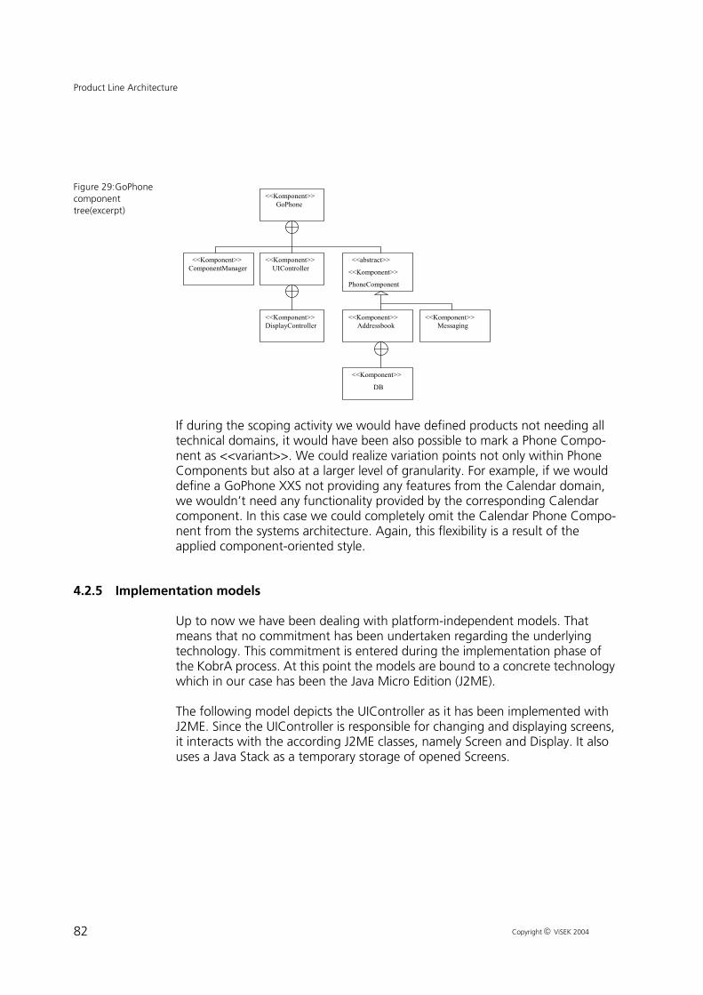
82
Product Line Architecture
Copyright ViSEK 2004
Figure 29:GoPhone component tree(excerpt)
If during the scoping activity we would have defined products not needing all technical domains, it would have been also possible to mark a Phone Compo-nent as <<variant>>. We could realize variation points not only within Phone Components but also at a larger level of granularity. For example, if we would define a GoPhone XXS not providing any features from the Calendar domain, we wouldn’t need any functionality provided by the corresponding Calendar component. In this case we could completely omit the Calendar Phone Compo-nent from the systems architecture. Again, this flexibility is a result of the applied component-oriented style.
4.2.5 Implementation models
Up to now we have been dealing with platform-independent models. That means that no commitment has been undertaken regarding the underlying technology. This commitment is entered during the implementation phase of the KobrA process. At this point the models are bound to a concrete technology which in our case has been the Java Micro Edition (J2ME).
The following model depicts the UIController as it has been implemented with J2ME. Since the UIController is responsible for changing and displaying screens, it interacts with the according J2ME classes, namely Screen and Display. It also uses a Java Stack as a temporary storage of opened Screens.
<<Komponent>> GoPhone
<<Komponent>> UIController
<<Komponent>> DisplayController
<<Komponent>> ComponentManager
<<abstract>>
<<Komponent>>
PhoneComponent
<<Komponent>>
DB
<<Komponent>> Addressbook
<<Komponent>> Messaging

83
Product Line Architecture
Copyright ViSEK 2004
Figure 30:Implemen-tation model
4.3 Variability Mechanisms
The product line architecture must support the intended product portfolio, that is, the common characteristics of the product family, the commonalities, define skeleton of architecture. The skeleton must in addition provide means for realiz-ing (at least) the expected variability, which leads to flexible architectural struc-tures.
For mobile phones the main challenges are
1 Languages: mobile phones are used all over the world and thus must support a large set of languages. Therefore, the translation from an internal represen-tation to the final language should be as late as possible to keep most of the software independent of language-specific issues.
2 User interface styles: there is a wide variety of displays and input devices sup-ported by concrete mobile phones. For instance, displays vary in size, resolu-tion, color depth, etc. To be efficient, the user interface should be developed once in a generic, style-independent way and then “only” specialized in the context of a concrete product.
3 Hardware variations: different phones are delivered with different resource characteristics, such as memory size, power consumption or processing

84
Product Line Architecture
Copyright ViSEK 2004
speed. These differences must be considered within the product line infra-structure. In the mobile phone case study, these constrains are not handled due to its emulation-based realization. However, these issues have been suc-cessfully solved in industrial contexts.
4 Feature configurations: As described in the scoping and the domain analysis chapters, different phones support a different set of features. The resolution of the variations should typically happen before the software is flashed to a phone because the limited resources do not allow a resolve them as late as at runtime.
In the context of this work (see [8]) we have identified three dimensions of prod-uct line implementation technologies used for handling variability: Component technologies, configuration management and generative features of program-ming languages including generators.
Ideally a product line implementation approach would combine mechanisms of this area in order to work around weaknesses and to bring together strengths of each dimension.
In the following sections we describe the use of each dimension in the GoPhone product line.
To achieve the flexibility required, the mobile phone case study makes use of several mechanisms.
Component architecture: as architectural style, component orientation has been selected. That is, software units communicate indirectly only via component manager (mediator). Hence, the implementations of components do not contain direct dependencies on other components but may resolve their context at runt-ime. For example, it is only possible to take the telephone number an SMS should be sent to from the addressbook if an addressbook exists. Whether the messaging component provides this feature could be resolved at runtime by checking with the component manager whether an addressbook component has been registered. This enables an easy plug in or out of optional components.
Additionally, components can be replaced by an alternative with identical inter-face without requiring any other changes.
UI Manager: we introduce an UI manager that keeps the rest of the software independent of any UI-specific issues. In the one direction, all kinds of user inputs are translated into internal user events; in the other direction, the dialogs and masks are referenced within the functional components in a technology-independent format. The UIManager resolves just before sending it to the dis-play the technology-independent reference with a concrete implementation of the UI elements.

85
Product Line Architecture
Copyright ViSEK 2004
The meaning and number of soft keys is handled analogously. With this approach, it is possible to use identical source code for significant portions of a mobile phone software and a desktop application similar to Microsoft Outlook.
The approach can be labeled as separation of concerns because the UIManager separates appearance from behavior, as well as program logic from concrete UI technology.
Hardware abstraction: abstract commands and user events are used rather than concrete buttons or menu structures. That is, if a menu entry is selected, its name is read and translated into a user event. This is different to an approach that interprets the third menu entry as a particular command or allows a specific set of commands to be invoked from a particular menu.
Programming language concepts: there are several design patterns available that create some kind of flexibility. The mobile phone architecture heavily uses design patterns. The state pattern is used to implement the state machine underlying a phone where menus represent states and the selection of menu entries correspond to state transitions.
The UIManager is an instance of the model-view-controller pattern (MVC). The state machine of a functional component is the controller, the data model owned by this component is the model, and the UIManager corresponds to the view.
Interfaces: In the architecture several interfaces are defined on which the imple-mentation of components is based. The components using these interfaces can be used independent of how and who (which component) implements these interfaces.
Aspect oriented programming: variant features that spread across many compo-nents have been implemented with Aspect-orientation. More on this can be found in Section 4.3.1.
Code generation: the variations between phones have been analyzed systemati-cally and thus the implementation of the phones will take this analysis into account. This allows to generate product variants according to the resolution of the variabilities in the context of a concrete product. In this case study we have developed a special generator that handles the different states of the mobile phone. See Section 5.5 for more details.
4.3.1 Aspect oriented programming
An optional feature can affect various core components. For example, if logging is supposed to be offered as an optional feature, delivering a corresponding

86
Product Line Architecture
Copyright ViSEK 2004
product means that many different operations must produce output for a log file.
Aspect Oriented Programming (see [9]) enables the modularization of such crosscutting features. This is done by the introduction of class-like constructs called aspects. The latter are encapsulating the crosscutting features.
AOP and its most popular Java binding called AspectJ enables crosscutting at the method level. This means that we can capture the methods that get affected by an optional feature and accordingly introduce the optional code. The latter happens at the bytecode level in a process called aspect weaving. AspectJ sup-ports the whole process by extending Java with new language constructs and by providing a special compiler that understands the aspect language and weaves code as necessary.
In this work we used AspectJ to encapsulate the T9 text recognition functional-ity (see Section 3.2.1). T9 was a good candidate to be implemented as an aspect because it crosscuts with all components providing editing facilities (e.g. Mes-saging, Address Book, Calendar). These components make use of text fields for enabling the user to edit text. So our goal was to introduce a new kind of text field namely one with text recognition capability.
To this end we firstly capture all operations that construct standard fields for text editing. Afterwards we replace that constructor calls by new ones that return objects of our T9 text field. This class extends the standard text field class. Finally we capture all calls to the insert method that is automatically invoked when a user types something and redirect these calls to our own implementa-tion.
Another interesting variability that we managed to handle with Aspect Orienta-tion was the interaction of two components. The Addressbook component sup-ports the management of contacts but the interface to the Management com-ponent for sending messages to these contacts is optional. We used AspectJ to encapsulate the interaction of the Addressbook and Messaging components into an aspect.
Figure 31 shows the aforementioned variability as a UML diagram that uses ste-reotypes for denoting the variant parts. As it can be seen the variability spreads across different components. The easiest way to handle this variation would be to use preprocessor directives for including the optional parts at variation points that are defined in the standard code.

87
Product Line Architecture
Copyright ViSEK 2004
Figure 31:Send Mes-sage To Contact Variability
AOP on the other hand provides the possibility of encapsulating the code that handles this variability in an aspect as it can be seen in Figure 32. Moreover the definition of the variation points is handled in the aspect itself and thus the stan-dard code does not to need to be changed at all. The aspect weaver assumes the responsibility of merging the aspect with the standard code.
Figure 32:Solution with AOP
The aspect SendMsgToContact contains a pointcut that picks up the handling of user actions and an advice that introduces additional handling for the SendMsg-ToContact action. The aspect also declares the realization of the IMessaging interface by the Messaging class and followingly adds the according method body (sendMsgToContact). Similarly it adds an additional method to the Addressbook class that gets called when the SendMsgToContact action is selected.

88
Infrastructure Usage
Copyright ViSEK 2004
5 Infrastructure Usage
5.1 Product Derivation Process
The product derivation process is driven by the decision models (Table 5). In order to create a product the decisions in the decision models have to be resolved and the actions connected to each resolution have to be executed. So each product configuration is maintained as a set of resolution models.
The requirements and architectural models of a product line member are obtained by resolving the domain and architecture decision model respectively. The product map (Table 3) can be used to validate the product requirements against the preplanned features from the scoping step.
The activity that follows the instantiation of the product line decision models is the product construction, which consists of the following:
1 Reuse of existing product line assets:
Assets that have been implemented during the development of previous instances, and therefore are part of the product line code history, are reused for the current product.
2 Implementation of non-existing product line assets:
Assets that are defined within the scope of the product line but have not been implemented during the development of previous instance are created.
These assets must be evaluated not only to satisfy this instances require-ments, but also for integration in the product line.
3 Implementation of product specifics:
Assets that lie outside the product line scope must be developed to fulfill spe-cific requirements of the current product.
5.2 Domain Model Instantiation
For specifying a product line member we ideally can use the domain model pro-duced in the course of the domain analysis process without doing major

89
Infrastructure Usage
Copyright ViSEK 2004
changes to it. Followingly we provide an example how a domain model can be instantiated towards a product-specific model.
For the example we assume that we want to build now the Go Phone XS which according to the Product Map (Table 3) has no attachable or insertable objects, no email or extended sms functionality, but T9 support. Therefore the decision model in Table 5 is reduced to the following resolution model:
Figure 33:GoPhone XS resolution model
The variability model for the Use Case send message is accordingly reduced to:
ID Question Subject Resolution Effect
1 Which kind of attach-ments is the phone capa-ble of?
Attach-ments
no objects remove Alt 1 and 2 from step 8 in UC ’send message’;remove Alt 1 and 2 from step 11 in UC ’show message’;remove steps 7 to 10 from UC ’show message’;remove Alt 1 from step 6 in UC ’show mes-sage’.
2 Which kind of insert-able objects is the phone capable of?
Inserts no items remove Alt 1 and 2 from step 7 in UC ’send message’;remove Alt 1 and 2 from step 6 in UC ’show message’.
3 T9 support? T9 yes step 6 of UC ’send message’ is obligatory;extension 6a of UC ’send message’ is obliga-tory;step 6 of UC ’start chat’ is obligatory;extension 6a of UC ’start chat’ is obligatory.
4 Which kinds of messages are sup-ported?
mes-sage types
only short messages
remove step 3 of UC ’send message’;remove Alt 2 from step 11 in UC ’send mes-sage’.

90
Infrastructure Usage
Copyright ViSEK 2004
Figure 34:Instanti-ated variability model for UC send message
The Use Case for this product is instantiated to:
1 Use Case name
Send message
2 Primary actor
mobile user
3 Scope
Software Package of Go Phones, Messaging domain
4 Limitation
This use-case is valid for all Go Phones except Go Car. Go Car has no messaging domain.
5 Level
user level
6 Stakeholders and interests
• mobile user (in the following ’user’): wants to send a newly composed text-message
• network: wants to receive protocol conform messages from the mobile
send message
message text editor networkrecipient
phone number
basic short message
normal
T9

91
Infrastructure Usage
Copyright ViSEK 2004
7 Precondition
The system shows the main menu.
8 Minimal Guarantee
The mobile keeps operating.
9 Success Guarantee
The message, entered by the user is sent via the network, so that the message reaches its destination in the same shape and content as the user typed it.
10 Main Success Scenario
1. The user chooses the menu-item to send a message.
2. The user chooses the menu-item to start a new message.
3. The system switches to a text editor.
4. The user enters the text message.
5. If T9 is activated, the system compares the entered word with the dictionary.
6. The user can not insert an item into the message.
7. The user can not attach any objects to the message.
8. The user chooses the menu-item to send the message.
9. The system asks the user for a recipient.
10. The user types the phonenumber or chooses the recipient from the address-book.
11. The system connects to the network and sends the message, then it waits for an acknowledgement.
12. The network sends an acknowledgement to the system.
13. The system shows an acknowledgement to the user that the message was succesfully sent.
14. The system asks the user if the message should be saved. If it should be saved, the system saves the message in the ‘sent-message’ folder
15. The system switches to the main menu.
11 Extensions:
2 a) The system does not have enough free memory for composing a new mes-sage. The system states an error message.
4 a) The user enters a symbol the system does not understand. The system shows the user that it does not understand the symbol (e.g. playing a beep tone).

92
Infrastructure Usage
Copyright ViSEK 2004
5 a) The user enters a letter. T9 does not find a match. The system shows the user that it does not understand the word (e.g. playing a beep tone). (The user has the possibility to switch T9 off now or enter the word manually).
11 a) The system tries to connect to the network and gets no response. The sys-tem tries again after a number of milliseconds (to be specified). If this try fails again, the system states a message that the message was not sent and the mes-sage is saved in the ‘outbox’ folder.
12 a) The network does not send an acknowledgement: The system tries again after a number of milliseconds (to be specified). If this try fails again, the system states a message that the message was not sent and the message is saved in the ‘outbox’ folder.
12 b) The network sends a message that the message can not be delivered/ is invalid. The system states a message that the message was not sent and the message is saved in the ‘outbox’ folder.
There is an incoming call during the Use Case: The current status is saved and the call is displayed. After the call the saved state is reestablished.
The user can terminate the UC via a menu item after steps 1, 2, 3, 4, 5, 6, 7, 8, 9, 10, 11, 14 and 15.
12 Non-functional requirements
• After the user chose send message the message has to be sent to the net-work within 2 sec.
• The text editor must provide easy navigation functionality (high usability). This usability is measured by the use of a customer questionnaire in which more than 60% of the questioned customers rate the usability at least ‘good’ on a scale: very bad, bad, average, good, very good. Furthermore, the time to edit one letter in a message with about 100 letters must be lower than 3 sec.
• The error-rate for sending messages should be below 0.2%. This rate does only cover errors caused by the mobile, e.g. messages that are not conform to the network-protocol.
With the help of the use cases, the feature and the decision model the require-ments on the messaging domain are now clear. With these common and vari-able requirements an architectural model con be built that covers all products of the Go-Phone product line.
5.3 Process Hierarchy Instantiation
During Process Hierarchy Instantiation we resolve the Process Hierarchy Model shown in Figure 24. The Resolution Model belonging to the mentioned process Hierarchy Model is shown in the next table

93
Infrastructure Usage
Copyright ViSEK 2004
Table 7: Process Hierarchy Resolution Model
Figure 35 depicts the result of applying the above resolution model to the Pro-cess Hierarchy Model.
Figure 35:Instanti-ated Process Model
According to the resolution model the processes Attach Object, Attach Item and Select Message Type are left out, whereas Select 9-Mode remains in the model.
5.4 Architecture Instantiation
Chapter 4 dealt with the architecture of the Go Phone product line or -more generally speaking- with domain design. During this activity the generic product line architecture of the Go Phone was developed. We will now exemplary instantiate the architecture for a concrete product, namely the Go Phone XS. According to the Product Map the Go Phone XS Architecture will have the fol-lowing components: Call Management, Ringing Tones, Calendar, Addressbook and Messaging. During the Application implementation activity we remove the genericity from the models of the components, which we've selected to be part of the product- specific architecture by removing the genericity from the models of their specification and realization. We choose the use case of Section 3.2.1,
ID Question Variation Point Resolution Effect
1 Process Select Message Type supported?
Select Message Type No remove Process Select Message Type
2 Process Attach Object supported Attach Object No remove Process Attach Object
3 Process Attach Item supported Attach Item No remove Process Attach Item
4 Process Select T9-Mode sup-ported
Select T9-Mode Yes remove stereotype <<variant>>

94
Infrastructure Usage
Copyright ViSEK 2004
where the Send Message to Contact option (discussed in Section 4.3.1), will be selected. Therefore the Figures 31 and 32 will be merged to the following fig-ure:
Figure 36:SendMsg-ToContact Resolved Model
The difference between the above figure and figure 31 is the absence of the <<variant>> stereotypes since the involved entities are selected in the derived product.
5.5 Code Generation
As mentioned earlier, another way to support variability in a product line archi-tecture is the use of code generators. The generation of code is usually parame-terized by a declarative specification, so that the generated output can be con-trolled in some way.
5.5.1 Increasing the efficiency of Component implementation
In the context of the GoPhone case study, we developed a XML/XSLT-technol-ogy based generator. At the beginning, goal of the generator was not support-ing the flexibility of the product line architecture. The generator was originally designed to increase the efficiency when the architecture is extended with addi-tional Phone Components. It is important to mention here, that the generator doesn't produce the complete application code from the declarative specifica-tion. The programmer still has to fill in code at dedicated places in the generated code. Increasing efficiency in this context means the shortening of development time for a new Phone Component, as a programmer is unburdened from fre-

95
Infrastructure Usage
Copyright ViSEK 2004
quently reoccurring coding tasks. Even more important is the fact, that the gen-erated code enforces a Phone Component's architecture, because a program-mer has to fill gaps at preplanned locations in the generated code. Moreover the generated code is tested and less error prone and coding guidelines are kept automatically. So efficiency also means an improvement of quality.
A prerequisite to the development of the generator was the already mentioned analysis of the technical domain of existing Phone Components. This included the simple comparison of code in corresponding class files, the analysis of the component structure and the analysis of the components behavior. The results of this analysis entered into the design of the generator. The explored common-alities between Phone Components are stored in code templates. Additional information and parameterizations for the generator are provided through a declarative XML-File. The generator uses this declaration to build class-files from the templates as well as directory structures and configuration files, which make up a Phone Component. A special case is the way the generator deals with visi-ble component behavior. The implementation of a Phone Component's behav-ior occurs in a very straightforward way using the GOF State Design Pattern as described in 4.1.2. To allow the generation of an instance of the GOF state pat-tern structure (i.e. an individual implementation of the pattern for the Phone Component under construction) through a generator, the declarative XML com-ponent specification is extended with the description of a finite state machine representing the components visual behavior.
5.5.2 Graphical Modelling of a Phone Component
During further development iterations, the generator was extended with an XMI-Interface. Using a simple UML-Profile with stereotypes, which constitutes a lightweight extension of the UML-Metamodel for our case study's domain, the Phone Component can be modelled with a UML-tool. The XMI output from the UML-Tool serves as input for the generator. It has several advantages to model the component graphically, especially in regard to the error proneness of a hand coded textual description of a component. Moreover the visualization with UML makes the specification more capable for human beings. The state machine part of the component specification for instance, can now be modelled with a UML state diagram. This approach conforms essentially to the ideas of the Model Driven Architecture.
5.5.3 Supporting Variability
At this point we want to return to our actual question: In what way can a gener-ator be used to support variability into the product line architecture. Until now the generator does not offer the mechanisms necessary to provide flexibility at generation-time for a component, but it would be no problem to add them. This

96
Infrastructure Usage
Copyright ViSEK 2004
would include the necessity to allow conditional code processing, where a deci-sion could serve as input.
One approach would be, to use different code templates depending on parame-ters passed to the generator. This could result in different implementation of methods, different class files, configuration files or directory structures. A more sophisticated idea, which is currently under development, is the flexible realiza-tion of component structure and component behavior even before code genera-tion time. Starting with a generic platform independent model (PIM), e.g. a KobrA UML model, we could instantiate models from it for special products. This could be done manually or ideally, with tool support. These instantiated models would also be platform-independent and after the instantiation, we can continue with an MDA approach and generate component code from these models. The tool has a built-in decision model, so it can produce the model for a component from the according generic model in dependence of the parameters passed to the tool. These parameters basically constitute the decision resolution model.
Figure 37:Compo-nent Instantiation Process
5.5.4 The technical realization
In this section, we will shortly discuss, how such a tool, consisting of a model transformer and a code generator, could look like.

97
Infrastructure Usage
Copyright ViSEK 2004
For the instantiation of generic models, we need, as mentioned above, another generator tool. Speaking in terms of a pipes and filters pattern, this tool is mainly serving as a model transformer and would be located in front of the existing code generator. The transformer tool is providing the code generator’s input in the form of the instantiated model. It does not generate application code - it just removes information from the generic model. If we decide to use an XMI-based solution, we could export the generic UML-Model to XMI and pass the decision-resolution-model to the transformer. It is then the task of the transformer to resolve the decisions and transform the XMI-File with the generic information to another XMI-File, only containing the model information for the specified component. Now a code generator tool can continue and produce for instance Java-Application Code. The code generator we need here would not profoundly differ from the generator, which was introduced at the beginning of this section.
Figure 38:Generic Calendar state dia-gram
Generally the code generator could be extended, so that in future it may be pos-sible to generate even method implementations from activity diagrams, but this discussion is out of the paper’s scope at the moment. More important at this point is the input provided to the generator, so we will take a look at a concrete example of a generic finite state machine model, showing a part of the behavior of a calendar component. We don’t use the aforementioned lightweight UML-Profile here, because it has no influence on the discussion. This model is shown in picture Figure 38 and there are several decisions that can be taken:
1 Is it possible to add an alert (e.g. a audible signal, when the entered time for an appointment is reached) to an appointment? The corresponding feature, setAlert, is shown in the state named EditEntryScreenState and is tagged with the stereotype variant.

98
Infrastructure Usage
Copyright ViSEK 2004
2 Is it possible to add send an Appointment to a recipient? This feature is repre-sented through the SendAppointmentToContactScreenState, which is also tagged with the stereotype variant.
3 And finally, dependent on the existence of the former feature, the decision: Is it possible to choose a recipients address from the address book?
This generic model could now be exported to XMI.We assume that our resolu-tion for the generic model would look like this:
It is possible to add an alert to an appointment, but it is not possible to send an appointment to a contact (consequently there’s no possibility to choose an recipients address from the address book). The resulting instantiated state model looks like the one shown in picture Figure 39.
Figure 39:Instanti-ated Calendar state diagram
This is exactly the step, that has to be done by the transformer tool. A prerequi-site to this is of course, that we have a more tool-comprehensible form of the resolution model so that the tool can remove the unused variant-tagged model elements from the XMI-File. Normally the representation of the instantiated model would just exist as XMI, but it should be no problem to visualize the transformed XMI, if the graphical information for the still existing elements is not removed from the XMI by the transformer tool.
Now we have the possibility to feed this instantiated model to the generator and can produce the code of the corresponding state machine using the state design pattern.
99
Infrastructure Usage
Copyright ViSEK 2004
5.5.5 Conclusion
There are a lot of open questions concerning the realization of such a tool. The existing code generator tool was designed to produce a code framework for a programmer and a lot of features are missing. The possibility to realize the com-ponents state machine from a state diagram is the most sophisticated part, but there should be further extensions to the code generator. It should be possible for instance, to preserve manually implemented code parts if the generator reruns. On the other hand, these manual implementations should also be avail-able for the code generator tool, if they can be reused in other variants of the component. Concerning a tool that can transform a generic model into a con-crete one, there has to be done further work, especially the resolution of depen-dencies within the generator will be most challenging. Perhaps it should be pos-sible to configure the generator with different decision models from outside.
All in all this approach appears promising, because it combines the ideas of the MDA with that of software product lines and so can fulfill the demands for flex-ibility at a very early stage in the implementation of the product line architec-ture.

100
Analysis and Future Work
Copyright ViSEK 2004
6 Analysis and Future Work
In this report we have shown how a software product line approach enables meeting one important challenge to software development, that is fulfilling dif-ferent customer and market needs. This is accomplished through the planning and creation of an infrastructure that manages the commonalities and variabili-ties of a family of software products and allows the efficient tailoring of cus-tomer-specific products.
By reading this report it becomes apparent that the creation of the aforemen-tioned infrastructure involves some initial effort, which is not found in singe-sys-tems development. However this effort pays off as more requirements are posed to the product line and more systems need to be delivered. The reason for that lies in the systematic planning being done in the early phases of product line engineering. This planning activity defines the scope where software reuse is expected to pay off. Reuse is the foundation of a product line approach and it is carried through all phases of product line development.
Reuse and component-based development are knowingly related and in this report we demonstrated how the PuLSEtm approach for product line engineer-ing can be combined with the KobrA method that supports component-based, model-driven development. Combining the concepts of product-line and model-driven architectures promises to address some of the key shortcoming of the former and to make the benefits of the latter available in the context of a family of products. As well as making product line engineering more attractive for industrial projects, therefore, it also provides a systematic way of leveraging the benefits of a product line viewpoint in tandem with the component and middle-ware technologies commonly associated with the MDA, such as CORBA, EJB, XML, SOAP, and .NET.
In our future work we intend to enrich our experiences with the combination of product-line and component-based development through additional case stud-ies especially from the embedded systems world where additional challenges come into play. Moreover we plan to refine our work in the area of software generators in order to automate to a sensible degree the management and der-ivation of products.

101
Glossary
Copyright ViSEK 2004
7 Glossary
In the following glossary, terms that are used for modelling are explained:
Attachment/ attachable object: An object that can be attached to a message as known from emails. E.g. a business card or a calendar entry.
Business Card: A business card is an extract of the addressbook of the phone. It contains all data of a user that is saved in the mobile (e.g. name, phone number, mailing address, email address).
Call: A call is an event arriving at the mobile or sent by one mobile to another with a request for voice communication between the two users.
Chat: A special application based on messages. Similar to the chat known from PC applications two users can communicate in a fast and easy way.
Folder: The messages and other objects are sorted in a folder-hierarchy. One folder can consist of several sub-folders. Folders like ’inbox’ or ’outbox’ are pre-defined, whereas other folders can be user-defined.
Insertable object: An object that can be inserted into a message (e.g. a picture). In contrast to an attached object, an inserted object is directly displayed when the message is displayed.
Message: A textual message sent from one mobile to another. A message can either be a basic short message, an extended short message or an email.
System: As we focus on software development, ’the system’ stays for the soft-ware subsystem of the mobile phone. If we want to address the hardware, the term ’the mobile’ is used.
User: This is the end-user of the mobile phone.

102
References
Copyright ViSEK 2004
8 References
[ 1 ] E. Gamma et al., Design Patterns - Elements of Reusable object-oriented software, Addison-Wesley, 1995
[ 2 ] Coleman, Derek et al., Object-Oriented Development, The Fusion Method, Englewood Cliffs: Prentice Hall, 1994
[ 3 ] Jean Marc de Baud, Klaus Schmid, A Systematic Approach to Derive the Scope of Software Product Lines, In Proceedings of the 21st international conference on Software engineering, Los Angeles CA, USA, 1999
[ 4 ] Joachim Bayer, Dirk Muthig, Tanya Widen, Customizable Domain Analy-sis, In Proceedings of the First International Symposium on Generative and Component-Based Software Engineering, 1999
[ 5 ] Anastasopoulos, Michalis; Bayer, Joachim; Flege, Oliver; Gacek, Cristina, A Process for Product Line Architecture Creation and Evaluation. PuLSE-DSSA - Version 2.0, IESE-Report, 038.00/E, Kaiserslautern, 2000
[ 6 ] Christian Bunse, Pattern-Based Refinement and Translation of Object-Ori-ented Models to Code, Stuttgart: Fraunhofer IRB Verlag, 2001
[ 7 ] Schmid, Klaus; Widen, Tanya, Customizing the PuLSE Product Line Approach to the Demands of an Organization, Software Process Technol-ogy EWSPT'2000, Berlin: Springer-Verlag, 2000
[ 8 ] PoLITe (Product Line Implementation Technologies) project home page, http://www.polite-project.de
[ 9 ] Aspect-Oriented Programming. Communications of the ACM Vol.44 No.10, October 2001
[ 10 ] M. Bory, S. Hartkopf, K. Kohler, and D. Rombach. Germany: Combining Software and Application Competencies, IEEE Software, July/August, 2001
[ 11 ] Frank van der Linden. Software Product Families in Europe: The Esaps and Café Projects. IEEE Software, 19(4):41–49, July/August 2002.
[ 12 ] Garry Chastek, editor. Software Product Lines: Proceedings of the Second Software Product Line Conference (SPLC2), LNCS 2379, San Diego, CA,

103
References
Copyright ViSEK 2004
2002. Springer.
[ 13 ] Frank van der Linden, editor. Software Product-Family Engineering. 4th International Workshop, PFE 2001, LNCS 2290, Bilbao, Spain, October 2001. Springer.
[ 14 ] E. Kamsties, K. Hörmann, and M. Schlich. Requirements Engineering in Small and Medium Enterprises: State-of-the-Practice, Problems, Solutions, and Technology Transfer, in Proceedings of the Conference on European Industrial Requirements Engineering, 1998
[ 15 ] S. Sanderson and M. Uzumeri. The Innovation Imperative - Strategies for Managing Product Models and Families, Chicago: Irwin, 1997
[ 16 ] Gacek, C.; Abd-Allah, A.; Clark, B.; & Boehm, B. “On the Definition of Software System Architecture.” Invited talk, First International Workshop on Architectures for Software Systems. Seattle, WA, April 1995.
[ 17 ] Kyo C. Kang et al., Feature-oriented Domain Analysis (FODA) Feasibility Study, Technical Report, CMU/SEI-90-TR-21, ESD-90-TR-222, Software Engineering Institute, Carnegie Mellon University, November 1990
[ 18 ] Alistair Cockburn, Writing Effective Use Cases, Boston: Addison-Wesley, 2001
[ 19 ] Atkinson et al., Component-Based Product Line Engineering with UML, Addison Wesley, 2002
[ 20 ] Paul C. Clements and Linda Northrop. Software Product Lines: Practices and Patterns. SEI Series in Software Engineering. Addison-Wesley, August 2001
[ 21 ] Klaus Schmid. An Assessment Approach to Analyzing Benefits and Risks of Product Line. In Proceedings of the 25th Annual International Com-puter Software and Applications Conference (COMPSAC 2001), pages 525--530, 2001
[ 22 ] Klaus Schmid. The Product Line Mapping Approach to Defining and Struc-turing Product Portfolios. In International Workshop on Requirements Engineering for Product Lines (REPL'02), Essen, Germany, September 2002
[ 23 ] Rini van Solingen, Egon Berghout The Goal/ Question/ Metric Method. A Practical Guide for Quality Improvement of Software Development. Lon-don: McGraw-Hill, 1999

104
References
Copyright ViSEK 2004
[ 24 ] Object Management Group. OMG Unified Modelling Language Specifica-tion, Version 1.4, September 2001.

Copyright 2004, Fraunhofer IESE.All rights reserved. No part of this publication may be reproduced, stored in a retrieval system, or trans-mitted, in any form or by any means including, without limitation, photocopying, recording, or otherwise, without the prior written permission of the publisher. Written permission is not needed if this publication is distributed for non-commercial purposes.
Document Information
Title: GoPhone - A Software Product Line in the Mobile Phone Domain
Date: 5. March 2004Report: IESE-025.04/EStatus: FinalDistribution: Public